EP4133953A1 - Atomizer and electronic cigarette - Google Patents
Atomizer and electronic cigarette Download PDFInfo
- Publication number
- EP4133953A1 EP4133953A1 EP21784710.2A EP21784710A EP4133953A1 EP 4133953 A1 EP4133953 A1 EP 4133953A1 EP 21784710 A EP21784710 A EP 21784710A EP 4133953 A1 EP4133953 A1 EP 4133953A1
- Authority
- EP
- European Patent Office
- Prior art keywords
- atomization
- outer housing
- side wall
- atomizer
- liquid
- Prior art date
- Legal status (The legal status is an assumption and is not a legal conclusion. Google has not performed a legal analysis and makes no representation as to the accuracy of the status listed.)
- Granted
Links
Images




Classifications
-
- A—HUMAN NECESSITIES
- A24—TOBACCO; CIGARS; CIGARETTES; SIMULATED SMOKING DEVICES; SMOKERS' REQUISITES
- A24F—SMOKERS' REQUISITES; MATCH BOXES; SIMULATED SMOKING DEVICES
- A24F40/00—Electrically operated smoking devices; Component parts thereof; Manufacture thereof; Maintenance or testing thereof; Charging means specially adapted therefor
- A24F40/40—Constructional details, e.g. connection of cartridges and battery parts
-
- A—HUMAN NECESSITIES
- A24—TOBACCO; CIGARS; CIGARETTES; SIMULATED SMOKING DEVICES; SMOKERS' REQUISITES
- A24F—SMOKERS' REQUISITES; MATCH BOXES; SIMULATED SMOKING DEVICES
- A24F40/00—Electrically operated smoking devices; Component parts thereof; Manufacture thereof; Maintenance or testing thereof; Charging means specially adapted therefor
- A24F40/10—Devices using liquid inhalable precursors
-
- A—HUMAN NECESSITIES
- A24—TOBACCO; CIGARS; CIGARETTES; SIMULATED SMOKING DEVICES; SMOKERS' REQUISITES
- A24F—SMOKERS' REQUISITES; MATCH BOXES; SIMULATED SMOKING DEVICES
- A24F40/00—Electrically operated smoking devices; Component parts thereof; Manufacture thereof; Maintenance or testing thereof; Charging means specially adapted therefor
- A24F40/40—Constructional details, e.g. connection of cartridges and battery parts
- A24F40/42—Cartridges or containers for inhalable precursors
-
- A—HUMAN NECESSITIES
- A24—TOBACCO; CIGARS; CIGARETTES; SIMULATED SMOKING DEVICES; SMOKERS' REQUISITES
- A24F—SMOKERS' REQUISITES; MATCH BOXES; SIMULATED SMOKING DEVICES
- A24F40/00—Electrically operated smoking devices; Component parts thereof; Manufacture thereof; Maintenance or testing thereof; Charging means specially adapted therefor
- A24F40/40—Constructional details, e.g. connection of cartridges and battery parts
- A24F40/44—Wicks
-
- A—HUMAN NECESSITIES
- A24—TOBACCO; CIGARS; CIGARETTES; SIMULATED SMOKING DEVICES; SMOKERS' REQUISITES
- A24F—SMOKERS' REQUISITES; MATCH BOXES; SIMULATED SMOKING DEVICES
- A24F40/00—Electrically operated smoking devices; Component parts thereof; Manufacture thereof; Maintenance or testing thereof; Charging means specially adapted therefor
- A24F40/40—Constructional details, e.g. connection of cartridges and battery parts
- A24F40/48—Fluid transfer means, e.g. pumps
- A24F40/485—Valves; Apertures
Definitions
- Embodiments of the present application relate to the technical field of electronic cigarettes, and in particular relate to an atomizer and an electronic cigarette.
- An electronic cigarette is a product for heating and atomizing a liquid substrate containing nicotine to generate an aerosol to be smoked by a user.
- the portion, achieving an atomization function, of the electronic cigarette is an atomizer, and the atomizer structurally includes a liquid storage cavity for storing the liquid substrate, a porous body for absorbing the liquid substrate from the liquid storage cavity, and a heating body for heating and atomizing the liquid substrate absorbed by the porous body.
- an air inlet for allowing air to enter and a smoke transmission pipe for outputting the aerosol are provided at the portion, corresponding to the heating body, of a housing of the atomizer.
- external air enters the atomizer from the air inlet and then carries the aerosol to be output through the smoke transmission pipe, to form a complete airflow circulation.
- An embodiment of the present application provides an atomizer, including an outer housing, the outer housing being internally provided with a liquid storage cavity for storing a liquid substrate, and an atomization assembly for atomizing the liquid substrate to generate an aerosol, and the atomization assembly including a first side wall and a second side wall opposite to each other, and an atomization surface extending from the first side wall to the second side wall; where a holder is provided within the outer housing, and the holder is provided with a first surface opposite to the atomization surface along the axial direction of the outer housing; and an atomization cavity is formed between the first surface and the atomization surface.
- the first surface is configured to be inclined towards the atomization surface along the extension direction of the atomization surface, and is configured to receive the liquid substrate seeped from the atomization assembly and/or condensate formed by condensation of the aerosol within the atomization cavity.
- the second surface is provided with grooves that absorb or retain the liquid substrate and/or condensate by capillary action.
- the outer housing is configured as a hollow cylinder having an open end
- the present application further provides an electronic cigarette, including a power supply apparatus and the atomizer as described above, the power supply apparatus is configured to supply power to the atomizer, and the atomizer is an atomization apparatus configured to atomize the liquid substrate to generate an aerosol for smoking.
- the outer housing is provided with a first communication port (not labeled) close to the first side wall, and the first communication port is convenient for outside air to enter the interior of the atomizer.
- a first end, opposite to the proximal end, of the smoke transmission pipe 11 is in communication with the smoking port A, and a second end, opposite to the distal end, of the smoke transmission pipe is connected to the atomization assembly 40, such that the aerosol generated by the atomization assembly 40 atomizing the liquid substrate is transmitted to the smoking port A for smoking.
- the atomization assembly may include a porous body 41 for absorbing the liquid substrate from the liquid storage cavity 30, and a heating element 42 for heating and atomizing the liquid substrate absorbed from the porous body 41.
- the porous body 41 may be substantially of, but not limited to, a block-shaped structure in the embodiments, including, depending on the situation of use, a liquid absorption surface 411 and an atomization surface 412 opposite to each other along the axial direction of the outer housing 10, that is, an upper surface and a lower surface of the block-shaped porous body 41 in FIG.
Landscapes
- Electrostatic Spraying Apparatus (AREA)
- Disinfection, Sterilisation Or Deodorisation Of Air (AREA)
Abstract
Description
- The present application claims priority to the
Chinese Patent Application No. 2020102812822, filed on April 10, 2020 - Embodiments of the present application relate to the technical field of electronic cigarettes, and in particular relate to an atomizer and an electronic cigarette.
- An electronic cigarette is a product for heating and atomizing a liquid substrate containing nicotine to generate an aerosol to be smoked by a user. The portion, achieving an atomization function, of the electronic cigarette is an atomizer, and the atomizer structurally includes a liquid storage cavity for storing the liquid substrate, a porous body for absorbing the liquid substrate from the liquid storage cavity, and a heating body for heating and atomizing the liquid substrate absorbed by the porous body. Furthermore, in order to transmit the aerosol in a smoking process, an air inlet for allowing air to enter and a smoke transmission pipe for outputting the aerosol are provided at the portion, corresponding to the heating body, of a housing of the atomizer. In the smoking process of the user, external air enters the atomizer from the air inlet and then carries the aerosol to be output through the smoke transmission pipe, to form a complete airflow circulation.
- Due to the configuration of an airflow circulation structure, the liquid substrate seeped from the porous body in a use process of the atomizer and condensate formed after the aerosol formed by heating is cooled in a transmission process can flow out of the air inlet after being accumulated in the atomizer, thereby causing oil seepage and pollution.
- Based on the above content, an improved patent No.
201820119392.7 - In order to solve the problem of seepage of a liquid substrate of an electronic cigarette in the prior art, embodiments of the present application provide an atomizer that can avoid seepage of the liquid substrate and improve the aerosol output efficiency.
- An embodiment of the present application provides an atomizer, including an outer housing, the outer housing being internally provided with a liquid storage cavity for storing a liquid substrate, and an atomization assembly for atomizing the liquid substrate to generate an aerosol, and the atomization assembly including a first side wall and a second side wall opposite to each other, and an atomization surface extending from the first side wall to the second side wall; where a holder is provided within the outer housing, and the holder is provided with a first surface opposite to the atomization surface along the axial direction of the outer housing; and an atomization cavity is formed between the first surface and the atomization surface.
- The first surface is configured to be inclined towards the atomization surface along the extension direction of the atomization surface, and is configured to receive the liquid substrate seeped from the atomization assembly and/or condensate formed by condensation of the aerosol within the atomization cavity.
- In a preferred embodiment, an air inlet for allowing external air to enter and an airflow channel for outputting the aerosol are further provided within the outer housing. The outer housing is provided with a first communication port close to the first side wall, and the outer housing is provided with a second communication port in communication with the atomization cavity close to the second side wall, such that an airflow entering the atomization cavity from the air inlet at least partially flows to the airflow channel along the extension direction of the atomization surface under the guidance of the first surface, and the atomization cavity is in airflow communication with the air inlet through the first communication port, and is in airflow communication with the airflow channel through the second communication port.
- In a preferred embodiment, the first communication port is opposite to at least a part of the first surface along the extension direction of the atomization surface.
- In a preferred embodiment, the holder further includes a second surface with the back facing the first surface along the axial direction of the outer housing, the second surface being configured to absorb or retain the liquid substrate and/or condensate received by the first surface.
- In a preferred embodiment, the holder is configured to further include a drainage side wall, and guide the liquid substrate and/or condensate received by the first surface to the second surface through the drainage side wall.
- In a preferred embodiment, the second surface is provided with grooves that absorb or retain the liquid substrate and/or condensate by capillary action.
- In a preferred embodiment, the holder includes a housing, and a liquid absorption component accommodated in the housing and capable of absorbing the liquid substrate and/or condensate by capillary action; where,
- the first surface is formed on the housing; and
- at least a part of the liquid absorption component is exposed out of the housing and forms the second surface.
- In a preferred embodiment, a projection of at least a part of the first surface on a plane perpendicular to the axial direction of the outer housing covers the atomization surface.
- In a preferred embodiment, the outer housing is configured as a hollow cylinder having an open end;
- an end cover is provided at the open end, and the air inlet is formed in the end cover; and
- a sealing mechanism for sealing the liquid storage cavity and accommodating and retaining the atomization assembly is further provided within the outer housing; and at least a part of the airflow channel is provided on the sealing mechanism.
- The present application further provides an electronic cigarette, including a power supply apparatus and the atomizer as described above, the power supply apparatus is configured to supply power to the atomizer, and the atomizer is an atomization apparatus configured to atomize the liquid substrate to generate an aerosol for smoking.
- With the use of the above atomizer, the inclined first surface on the holder is used for receiving the seeped liquid substrate and condensate, and guiding the airflow within the atomization cavity, which reduces liquid seepage, and guides and improves output of the aerosol.
- One or more embodiments are illustrated by pictures in the corresponding accompanying drawings, which are not intended to limit the embodiments, in which elements having the same reference numerals represent similar elements, and the figures of the accompanying drawings are not intended to constitute a scale limitation unless specifically stated otherwise.
-
FIG. 1 is a schematic diagram of an electronic cigarette according to an embodiment; -
FIG. 2 is a schematic structural diagram of an atomizer inFIG. 1 in another perspective; -
FIG. 3 is an exploded schematic diagram of components of the atomizer shown inFIG. 2 before assembly; -
FIG. 4 is a schematic diagram of a cross section of the atomizer shown inFIG. 2 along the width direction; -
FIG. 5 is a schematic diagram of a cross section of the atomizer shown inFIG. 2 along the thickness direction; -
FIG. 6 is a schematic structural diagram of a holder inFIG. 3 in another perspective; -
FIG. 7 is a schematic structural diagram after an end cover and the holder inFIG. 3 are assembled; -
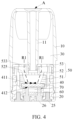
FIG. 8 is a schematic structural diagram of a holder according to another embodiment; and -
FIG. 9 is a schematic diagram of a cross section of a holder according to another embodiment. - To facilitate the understanding of the present application, the present application will be described in more detail below with reference to the accompanying drawings and specific embodiments.
- Embodiments of the present application provides an electronic cigarette product for heating and atomizing a liquid substrate. In an embodiment, a common flat cigarette shown in
FIG. 1 andFIG. 2 is used as an example for illustration, including anatomizer 100 for atomizing a liquid substrate, and apower supply apparatus 200 for supplying power to theatomizer 100. Thepower supply apparatus 200 is further provided with conductiveelastic pins 210 which are configured to be correspondingly connected to theatomizer 100 for electric conduction; and amagnet 220 that is correspondingly magnetically attracted to a magnetic attraction element on theatomizer 100. - The detailed structure of the
atomizer 100 can refer to the exploded schematic diagram ofFIG. 3 and the cross-sectional schematic diagram ofFIG. 4 , including:
a hollow cylindricalouter housing 10, theouter housing 10 having a proximal end and a distal end opposite to each other along the axial direction; where according to the requirements of common use, the proximal end is configured to be the end at which a user smokes an aerosol, and the distal end is configured to be the end to which thepower supply apparatus 200 is assembled and connected; for ease of description, theouter housing 10 further has afirst side wall 110 and asecond side wall 120 opposite to each other along the thickness direction. - Based on the above differences of use, a smoking port A is provided at the proximal end of the
outer housing 10, for the user to conduct a smoking operation; the distal end of theouter housing 10 is designed to be open and adetachable end cover 20 is installed thereon, and the open structure of the distal end of the outer housing is configured to install all necessary functional parts into theouter housing 10. - In some embodiments, the outer housing is provided with a first communication port (not labeled) close to the first side wall, and the first communication port is convenient for outside air to enter the interior of the atomizer.
- In some embodiments, the outer housing is provided with a second communication port (not labeled) close to the second side wall, and the second communication port is convenient for air inside the atomizer to flow out of the atomizer.
- Furthermore, the
outer housing 10 is internally provided with aliquid storage cavity 30 for storing the liquid substrate and anatomization assembly 40 for absorbing the liquid substrate from theliquid storage cavity 30 and heating and atomizing the same. Specifically, in the cross-sectional schematic structural diagram shown inFIG. 4 , asmoke transmission pipe 11 provided along the axial direction is provided within theouter housing 10. A space between an outer wall of thesmoke transmission pipe 11 and an inner wall of theouter housing 10 forms aliquid storage cavity 30 for storing the liquid substrate. A first end, opposite to the proximal end, of thesmoke transmission pipe 11 is in communication with the smoking port A, and a second end, opposite to the distal end, of the smoke transmission pipe is connected to theatomization assembly 40, such that the aerosol generated by theatomization assembly 40 atomizing the liquid substrate is transmitted to the smoking port A for smoking. - Referring to the structure of the
atomization assembly 40 shown inFIG. 3 , the atomization assembly may include aporous body 41 for absorbing the liquid substrate from theliquid storage cavity 30, and aheating element 42 for heating and atomizing the liquid substrate absorbed from theporous body 41. As shown inFIG. 3 , theporous body 41 may be substantially of, but not limited to, a block-shaped structure in the embodiments, including, depending on the situation of use, aliquid absorption surface 411 and anatomization surface 412 opposite to each other along the axial direction of theouter housing 10, that is, an upper surface and a lower surface of the block-shapedporous body 41 inFIG. 3 , where theatomization surface 412 is formed by extending from thefirst side wall 110 to thesecond side wall 120. In addition, theliquid absorption surface 411 is opposite to theliquid storage cavity 30 and in direct or indirect contact with the liquid substrate within theliquid storage cavity 30 so as to absorb the liquid substrate. Then, a porous structure within theporous body 41 transfers the liquid substrate to theatomization surface 412 to be heated and atomized to form the aerosol, and the aerosol is released from theatomization surface 412. According to the structure of theporous body 41 shown inFIG. 3 , because theliquid absorption surface 411 and theatomization surface 412 are parallel to each other, the movement directions of the liquid substrate and the aerosol within theporous body 41 are perpendicular to the plane of theatomization surface 412. The aerosol and liquid substrate will move more smoothly within theporous body 41 and be more convenient to manufacture. - In some embodiments, the
porous body 41 may be made of a porous ceramic, porous glass ceramic, porous glass or another hard capillary structure. Theheating element 42 is preferably formed on theatomization surface 412 by means of mixing conductive raw material powder with a printing aid to form paste and then sintering after printing, such that all or most of the surface of the heating element is tightly combined with theatomization surface 412, and the effects of being high in atomization efficiency, less in heat loss, capable of preventing dry burning or greatly reducing dry burning and the like are achieved. Theheating element 42 may be made of stainless steel, nickel-chromium alloy, iron-chromium-aluminum alloy, metallic titanium, or the like in some embodiments. - Furthermore, referring to
FIG. 2 to FIG. 4 , in order to facilitate installation and fixation of theatomization assembly 40 and to seal theliquid storage cavity 30, asealing mechanism 50 is further provided within theouter housing 10, and thesealing mechanism 50 includes asilica gel sleeve 51, arigid support sleeve 52, and asilica gel seat 53, which seal the port of theliquid storage cavity 30 and also retain and fix theatomization assembly 40 inside, - The structure and shape of the
silica gel sleeve 51 are not limited. In some embodiments, thesilica gel sleeve 51 is substantially annular, and an interior hollow 511 of the silica gel sleeve is configured to accommodate theatomization assembly 40 and be sleeved outside theatomization assembly 40 in a flexible fitting manner. - The
support sleeve 52 supports and protects theatomization assembly 40 sleeved with thesilica gel sleeve 51. In some embodiments, thesupport sleeve 52 may include a substantially cylindricalmain body portion 521 and aclamping wall 522 extending downwardly from a bottom surface of themain body portion 521. The clampingwall 522 is C-shaped, thereby forming a retainingcavity 523 within the clampingwall 522 for accommodating and retaining thesilica gel sleeve 51 and theatomization assembly 40. Thesupport sleeve 52 is provided with anairflow channel 524 on the side opposite to thefirst side wall 110 of theouter housing 10, for outputting the aerosol generated by theatomization surface 412. First liquid guide holes 525 are formed in thesupport sleeve 52 for transferring the liquid substrate to theliquid absorption surface 411. - In some embodiments, at least a part of the
airflow channel 524 is provided on the sealing mechanism. - The
silica gel seat 53 is provided at the end, facing the distal end, of theliquid storage cavity 30, and the shape of the silica gel seat is matched with a cross section of an inner contour of theouter housing 10, so as to seal theliquid storage cavity 30, and prevent the liquid substrate from being seeped out of theliquid storage cavity 30. Furthermore, in order to prevent the tightness of sealing from being affected by shrinkage deformation of thesilica gel seat 53 made of a flexible material, the aboverigid support sleeve 52 is accommodated in thesilica gel seat 53 to provide support. In a matched structure, thesilica gel seat 53 is provided with two oppositesecond clamping walls 531 extending downwards from the bottom surface, and anaccommodating cavity 532 for accommodating themain body portion 521 of thesupport sleeve 52 is formed between the twosecond clamping walls 531. Meanwhile, two second liquid guide holes 533 and an airpipe insertion hole 534 are formed in thesilica gel seat 53; where the two second liquid guide holes 533 correspond to the two first liquid guide holes 525 in thesupport sleeve 52, such that the liquid substrate within theliquid storage cavity 30 can flow to theliquid absorption surface 411 of theporous body 41 to be absorbed after passing through the second liquid guide holes 533 and the first liquid guide holes 525. The airpipe insertion hole 534 is configured to allow the lower end of thesmoke transmission pipe 11 to be inserted in, and meanwhile, after installation, thesmoke transmission pipe 11 is in airflow communication with theairflow channel 524, to output the generated aerosol to the smoking port A. - Furthermore, in order to stabilize the
sealing mechanism 50 within theatomizer 100, theend cover 20 has twofirst support arms 21 standing on a top surface of acover body 21 for supporting thesealing mechanism 50. - Meanwhile, the
end cover 20 is provided with a first mountinghole 22, a second mountinghole 23 and anair inlet 24. Amagnetic element 25, such as a magnet or a ferromagnetic element, which can be magnetically attracted to amagnet 220 of thepower supply apparatus 200 is installed within the first mountinghole 22, and anelectrode post 26 is installed within the second mountinghole 23 and is configured to supply power to theheating element 42 as a power supply electrode after being connected to the conductiveelastic pins 210 of thepower supply apparatus 200. Theair inlet 24 is configured to allow the outside air to enter theatomizer 10 during a smoking process. - When in use, as shown by an arrow R1 in
FIG. 4 , the liquid substrate enters an annular space of thesilica gel sleeve 51 after passing through the second liquid guide holes 533 and the first liquid guide holes 525 from theliquid storage cavity 30, and is absorbed by theliquid absorption surface 411 of theporous body 41, and transferred to theatomization surface 412 to be heated and atomized by theheating element 42, so as to form an aerosol for release. - Furthermore, in order to enable the aerosol to be released and transferred more smoothly, referring to
FIG. 3 andFIG. 4 , aholder 60 is provided between theend cover 20 and theatomization surface 412. Theholder 60 keeps certain spacing from theatomization surface 412 for forming anatomization cavity 70 to release the aerosol. - Furthermore, referring to
FIG. 3 andFIG. 7 , theair inlet 24 is configured to be positioned close to thesecond side wall 120 of theouter housing 10 such that the air inlet and theairflow channel 524 are respectively positioned on two sides of theatomization cavity 70. Furthermore, referring toFIG. 3 ,FIG. 5 andFIG. 7 , in the direction of a smoking airflow, the air entering from theair inlet 24 enters theatomization cavity 70 from the position close to thesecond side wall 120, and then is output to thesmoke transmission pipe 11 through theairflow channel 524 close to thefirst side wall 110 after passing through theatomization cavity 70 along the thickness direction of theouter housing 10. When the user smokes, an airflow can pass through thewhole atomization cavity 70, such that the aerosol within theatomization cavity 70 can be guided out along with the airflow to the maximum extent to reduce retention, thereby improving smoke output efficiency, and avoiding generation of the condensate within theatomization cavity 70. - In some embodiments, the
air inlet 24 is in communication with the first communication port, which is convenient for the outside air to enter the atomization cavity. - In some embodiments, the
airflow channel 524 is in communication with the second communication port, which is convenient for the air within theatomization cavity 70 to flow out. - Furthermore, referring to
FIG. 5, FIG. 6 andFIG. 7 , theholder 60 is substantially block-shaped and has afirst surface 61 and asecond surface 62 opposite to each other, where thefirst surface 61 is opposite to theatomization surface 412 and keeps certain spacing from the same to form theatomization cavity 70. In design, thisfirst surface 61 is inclined, particularly inclined upwards along the direction close to thefirst side wall 110. On one hand, the function of the first surface is to guide the airflow by means of the inclined design, as shown by an arrow R2 inFIG. 6 , the airflow aslant flows out under the guidance of thefirst surface 61; and on the other hand, the condensate formed by condensation of the aerosol within theatomization cavity 70 after the aerosol encounters cold air and the liquid substrate seeped downwards from theatomization assembly 40 can be received by thefirst surface 61, gradually flow along the direction of an arrow R3 inFIG. 6 under the guidance of the inclinedfirst surface 61, and fall off from thedrainage side wall 64 of theholder 60. - Furthermore, the
holder 60 is further provided with a throughhole 63 passing through theatomizer 100 along the length direction, and the powersupply electrode post 26 passes through the throughhole 63 and then abuts against two ends of theheating element 42 on theatomization surface 412 to conduct electricity. - In a preferred embodiment shown in
FIG. 7 , the condensate flowing down from theholder 60 will gradually flow into a gap between thesecond surface 62 and theend cover 20, and the port height of theair inlet 24 within theend cover 20 is between the uppermost and lowermost of the inclinedfirst surface 61. Therefore, the air flowing out of the port of theair inlet 24 is directed towards a certain middle portion of thefirst surface 61, such that thefirst surface 61 is able to at least partially guide the airflow passing through theatomization cavity 70. - Furthermore, in order to prevent the condensate dripping from the
holder 60 to the end cover 20 from being seeped out of the first mountinghole 22 and the second mountinghole 23 of theend cover 20,FIG. 8 shows a schematic diagram of aholder 60 according to another preferred embodiment.Several grooves 621a are provided on thesecond surface 62a opposite to theend cover 20, and the condensate can be adsorbed and retained by thegrooves 621a using a capillary principle, further avoiding seepage of the condensate or the received liquid substrate. It can also be seen fromFIG. 8 that thegrooves 621a extend along the thickness direction of theatomizer 100, that is, parallel to the direction in which the airflow passes through theatomization cavity 70, such that a fluid force in the airflow promotes adsorption. In other variable embodiments, thegrooves 621a may also be arranged in a bent, crossed, or the like manner. Alternatively, in other variable embodiments, thegrooves 621a may be replaced with other capillary structures capable of adsorbing the condensate or liquid substrate by capillary action, such as structures having capillary pores or bumps. - Alternatively, in another preferred embodiment, referring to
FIG. 9 , aholder 60b is formed by combining two components, specifically including:
ahousing 610b and aliquid absorption component 620b, thehousing 610b having afirst surface 61b and asecond surface 62b opposite to each other, where thefirst surface 61b is an inclined cambered surface and is configured to guide the airflow and receive the condensate; thehousing 610b is internally provided with an open cavity located on thesecond surface 62b, and theliquid absorption component 620b configured to adsorb and retain the condensate is provided within the cavity; theliquid absorption component 620b is made of sponge, porous ceramic or foam materials or materials capable of absorbing liquid by capillary action, such that when the received condensate flows from thedrainage side wall 64b to a gap with theend cover 20, the condensate can be absorbed by the surface, exposed out of the opening of thehousing 610b, of theliquid absorption component 620b, thereby eliminating seepage of the condensate or liquid substrate. - In some embodiments, at least a part of the surface of the
liquid absorption component 620b is exposed out of thehousing 610b and forms thesecond surface 62b. - In some embodiments, at least a part of the first surface is opposite to the first communication port along the extension direction of the atomization surface.
- Furthermore, in a preferred embodiment, a projection of the
first surface 61 of theholder 60 on a plant perpendicular to the axial plane of the outer housing at least partially covers the atomization surface. Preferably, the projection along the axial direction of theatomizer 100 is greater than theatomization surface 412, and completely covers theatomization surface 412. Meanwhile, it can be seen fromFIG. 5 andFIG. 7 that the structural portion, forming theair inlet 24, of theend cover 20 is not in contact with thedrainage side wall 64 of theholder 60 along the thickness direction of theatomizer 100
and kept certain spacing, about 5 mm, from the same, such that the condensate can be smoothly guided, through thedrainage side wall 64 of theholder 60, from thefirst surface 61 to thesecond surface 62 for absorption. - According to the above atomizer of the electronic cigarette, the atomization cavity is formed between the atomization surface and the holder, and the airflow passes through the whole atomization cavity in the smoking process, such that the aerosol within the atomization cavity can be guided out along with the airflow to the maximum extent to reduce retention; furthermore, the holder can receive and guide the condensate to the second surface, such that the condensate can be effectively prevented from being smoked along with the airflow or seeped.
- It should be noted that the preferred embodiments of the present application are given in the description and the accompanying drawings of the present application, but are not limited to the embodiments described in the description, and furthermore, for those of ordinary skill in the art, improvements or transformations can be made according to the above description, and all these improvements and transformations should fall within the protection scope of the appended claims of the present application.
Claims (10)
- An atomizer, comprising an outer housing, the outer housing being internally provided with a liquid storage cavity for storing a liquid substrate, and an atomization assembly for atomizing the liquid substrate to generate an aerosol, and the atomization assembly comprising a first side wall and a second side wall opposite to each other, and an atomization surface extending from the first side wall to the second side wall, wherein a holder is provided within the outer housing, and the holder is provided with a first surface opposite to the atomization surface along the axial direction of the outer housing; an atomization cavity is formed between the first surface and the atomization surface; and
the first surface is configured to be inclined towards the atomization surface along the extension direction of the atomization surface, and is configured to receive the liquid substrate seeped from the atomization assembly and/or condensate formed by condensation of the aerosol within the atomization cavity. - The atomizer according to claim 1, wherein an air inlet for allowing external air to enter and an airflow channel for outputting the aerosol are further provided within the outer housing; and
the outer housing is provided with a first communication port close to the first side wall, and the outer housing is provided with a second communication port in communication with the atomization cavity close to the second side wall, such that an airflow entering the atomization cavity from the air inlet at least partially flows to the airflow channel along the extension direction of the atomization surface under the guidance of the first surface, and the atomization cavity is in airflow communication with the air inlet through the first communication port, and is in airflow communication with the airflow channel through the second communication port. - The atomizer according to claim 2, wherein the first communication port is opposite to at least a part of the first surface along the extension direction of the atomization surface.
- The atomizer according to any one of claims 1-3, wherein the holder further comprises a second surface with the back facing the first surface along the axial direction of the outer housing, the second surface being configured to absorb or retain the liquid substrate and/or condensate received by the first surface.
- The atomizer according to claim 4, wherein the holder further comprises a drainage side wall, and is configured to guide the liquid substrate and/or condensate received by the first surface to the second surface through the drainage side wall.
- The atomizer according to claim 4, wherein the second surface is provided with grooves that absorb or retain the liquid substrate and/or condensate by capillary action.
- The atomizer according to claim 4, wherein the holder comprises a housing, and a liquid absorption component accommodated in the housing and capable of absorbing the liquid substrate and/or condensate by the capillary action; wherein,the first surface is formed on the housing; andat least a part of the liquid absorption component is exposed out of the housing and forms the second surface.
- The atomizer according to any one of claims 1-3, wherein a projection of at least a part of the first surface on a plane perpendicular to the axial direction of the outer housing covers the atomization surface.
- The atomizer according to claim 2, wherein the outer housing is configured as a hollow cylinder having an open end;an end cover is provided at the open end, and the air inlet is formed in the end cover; anda sealing mechanism for sealing the liquid storage cavity and accommodating and retaining the atomization assembly is further provided within the outer housing; and at least a part of the airflow channel is provided on the sealing mechanism.
- An electronic cigarette, comprising a power supply apparatus and the atomizer according to any one of claims 1-9, the power supply apparatus being configured to supply power to the atomizer, and the atomizer being configured to atomize a liquid substrate to generate an aerosol for smoking.
Applications Claiming Priority (2)
| Application Number | Priority Date | Filing Date | Title |
|---|---|---|---|
| CN202010281282.2A CN113508924B (en) | 2020-04-10 | 2020-04-10 | Atomizers and e-cigarettes |
| PCT/CN2021/086418 WO2021204285A1 (en) | 2020-04-10 | 2021-04-12 | Atomizer and electronic cigarette |
Publications (3)
| Publication Number | Publication Date |
|---|---|
| EP4133953A1 true EP4133953A1 (en) | 2023-02-15 |
| EP4133953A4 EP4133953A4 (en) | 2023-09-20 |
| EP4133953B1 EP4133953B1 (en) | 2026-05-06 |
Family
ID=78023669
Family Applications (1)
| Application Number | Title | Priority Date | Filing Date |
|---|---|---|---|
| EP21784710.2A Active EP4133953B1 (en) | 2020-04-10 | 2021-04-12 | Atomizer and electronic cigarette |
Country Status (4)
| Country | Link |
|---|---|
| US (1) | US20230134641A1 (en) |
| EP (1) | EP4133953B1 (en) |
| CN (1) | CN113508924B (en) |
| WO (1) | WO2021204285A1 (en) |
Families Citing this family (17)
| Publication number | Priority date | Publication date | Assignee | Title |
|---|---|---|---|---|
| EP3972433B1 (en) * | 2019-05-21 | 2023-11-08 | Philip Morris Products S.A. | Generating aerosol using vibration and heating in a vaporizer device |
| CN217012766U (en) * | 2021-05-12 | 2022-07-22 | 东莞富强电子有限公司 | Electronic cigarette |
| CN115363255B (en) * | 2021-10-29 | 2025-12-19 | 深圳市华诚达精密工业有限公司 | Heating atomization assembly, atomization device and electronic atomizer thereof |
| WO2023070978A1 (en) * | 2021-10-29 | 2023-05-04 | 深圳市卓力能技术有限公司 | Atomizer |
| CA212411S (en) * | 2021-11-03 | 2024-03-04 | Shenzhen Relx Tech Co Ltd | Conductive Pin of a Pod for an Electronic Cigarette |
| CN216293030U (en) * | 2021-11-05 | 2022-04-15 | 深圳市艾溹技术研究有限公司 | Atomizing seat, atomizer and electronic atomization device |
| CN217851325U (en) * | 2021-12-20 | 2022-11-22 | 江门摩尔科技有限公司 | Power supply module and electronic atomization device thereof |
| CN220800051U (en) * | 2021-12-30 | 2024-04-19 | 深圳麦克韦尔科技有限公司 | Heating component, atomizer and electronic atomization device |
| CN114365874B (en) * | 2022-01-11 | 2023-07-04 | 深圳市华微矽电子科技有限公司 | Efficient atomization device and application thereof in electronic cigarette |
| CN114259084A (en) * | 2022-01-17 | 2022-04-01 | 海南摩尔兄弟科技有限公司 | Electronic atomization device and atomizer thereof |
| CN218354676U (en) * | 2022-07-29 | 2023-01-24 | 深圳麦克韦尔科技有限公司 | Atomization assembly, atomizer and electronic atomization device |
| CN116491714A (en) * | 2023-05-30 | 2023-07-28 | 深圳市吉迩科技有限公司 | One-way valve anti-reflux electronic atomizer |
| WO2024250241A1 (en) * | 2023-06-08 | 2024-12-12 | 深圳市华诚达精密工业有限公司 | Electronic heating atomization assembly capable of recycling liquid in air change channel, and electronic heating atomization device |
| CN119279272A (en) * | 2023-07-10 | 2025-01-10 | 深圳市合元科技有限公司 | Aerosol generating device, atomizer and power supply mechanism |
| GB202311313D0 (en) * | 2023-07-24 | 2023-09-06 | Nicoventures Trading Ltd | Aerosol provision system with condensate capture |
| CN117179385B (en) * | 2023-09-21 | 2026-01-02 | 深圳市康泓威科技有限公司 | Electro-nebulizer with leak-proof structure |
| WO2025138459A1 (en) * | 2023-12-29 | 2025-07-03 | 深圳市合元科技有限公司 | Electronic atomization device and liquid storage component |
Family Cites Families (12)
| Publication number | Priority date | Publication date | Assignee | Title |
|---|---|---|---|---|
| CN102196866B (en) * | 2008-10-24 | 2014-08-06 | 松下电器产业株式会社 | Surface acoustic wave atomizer |
| US11117068B2 (en) * | 2014-10-20 | 2021-09-14 | Numerical Designs, Inc. | Microfluidic-based apparatus and method for vaporization of liquids |
| EP3165102B1 (en) * | 2016-09-06 | 2021-09-01 | Fontem Holdings 1 B.V. | A refill adapter cap for a refill receptacle to refill liquid in an electronic smoking device |
| CN206079029U (en) * | 2016-09-09 | 2017-04-12 | 深圳市合元科技有限公司 | Electronic cigarette atomizer |
| CN207444273U (en) * | 2017-06-30 | 2018-06-05 | 珠海优德科技有限公司 | A kind of electronic smoke atomizer of single-shot side air inlet oil dripping |
| CN209346085U (en) * | 2018-05-04 | 2019-09-06 | 深圳麦克韦尔科技有限公司 | Electronic cigarette and its atomising device |
| GB2576710B (en) * | 2018-08-23 | 2022-06-22 | All Vape Ltd | A pod |
| CN210203317U (en) * | 2019-05-07 | 2020-03-31 | 深圳市合元科技有限公司 | Atomizers and Electronic Cigarettes |
| CN110279158B (en) * | 2019-07-16 | 2025-02-18 | 深圳达钿科技有限公司 | A heating sheet for atomizer, atomizer and electronic cigarette |
| CN110638101B (en) * | 2019-09-30 | 2024-07-05 | 深圳麦克韦尔科技有限公司 | Atomizer and electronic atomization device |
| KR102697180B1 (en) * | 2019-09-30 | 2024-08-20 | 센젠 스무어 테크놀로지 리미티드 | Electronic ignition device and ignition device thereof |
| EP3799742A1 (en) * | 2019-10-02 | 2021-04-07 | Nerudia Limited | Smoking substitute component |
-
2020
- 2020-04-10 CN CN202010281282.2A patent/CN113508924B/en active Active
-
2021
- 2021-04-12 EP EP21784710.2A patent/EP4133953B1/en active Active
- 2021-04-12 WO PCT/CN2021/086418 patent/WO2021204285A1/en not_active Ceased
- 2021-04-12 US US17/918,113 patent/US20230134641A1/en active Pending
Also Published As
| Publication number | Publication date |
|---|---|
| CN113508924A (en) | 2021-10-19 |
| US20230134641A1 (en) | 2023-05-04 |
| EP4133953A4 (en) | 2023-09-20 |
| EP4133953B1 (en) | 2026-05-06 |
| WO2021204285A1 (en) | 2021-10-14 |
| CN113508924B (en) | 2026-05-05 |
Similar Documents
| Publication | Publication Date | Title |
|---|---|---|
| EP4133953B1 (en) | Atomizer and electronic cigarette | |
| CN210203317U (en) | Atomizers and Electronic Cigarettes | |
| EP3991580B1 (en) | Electronic cigarette atomiser and electronic cigarette | |
| US12426636B2 (en) | E-cigarette vaporizer and e-cigarette that can collect and hold condensate from aerosol | |
| US12022866B2 (en) | Atomizer and electronic cigarette | |
| EP4136989B1 (en) | Electrically-heated aerosol producing apparatus | |
| EP3569074A1 (en) | Cigarette cartridge, atomizer and electronic cigarette thereof | |
| WO2022083697A1 (en) | Atomizer and electronic atomization device | |
| CN213604379U (en) | Electronic Cigarettes and Electronic Cigarettes | |
| CN212464879U (en) | Nebulizer and aerosol generating device | |
| CN213344341U (en) | Electronic Cigarettes and Electronic Cigarettes | |
| CN214156229U (en) | an electronic atomizer | |
| WO2022105801A1 (en) | Aerosol generating apparatus | |
| US12527354B2 (en) | Atomizer and aerosol generation device | |
| CN209518264U (en) | Atomizer and electronic cigarette | |
| CN212545544U (en) | Atomizing core, atomizer and electronic atomization device | |
| CN216088866U (en) | Electron smog spinning disk atomiser's casing, electron smog spinning disk atomiser and electron cigarette | |
| CN214257969U (en) | Atomizing storehouse and atomizer | |
| CN113876039A (en) | Heating core assembly, atomizing device and atomizing equipment | |
| CN216701659U (en) | Heating core assembly, atomizing device and atomizing equipment | |
| CN105249538A (en) | Liquid absorption device, heating device, atomization head and electronic cigarette of electronic cigarette atomizer | |
| CN216220213U (en) | an electronic atomizer | |
| CN212260480U (en) | Atomization component of electronic cigarette and electronic cigarette | |
| WO2022156718A1 (en) | Atomiser and electronic atomising apparatus | |
| RU2854720C2 (en) | Electronic spraying device (variants) |
Legal Events
| Date | Code | Title | Description |
|---|---|---|---|
| STAA | Information on the status of an ep patent application or granted ep patent |
Free format text: STATUS: THE INTERNATIONAL PUBLICATION HAS BEEN MADE |
|
| PUAI | Public reference made under article 153(3) epc to a published international application that has entered the european phase |
Free format text: ORIGINAL CODE: 0009012 |
|
| STAA | Information on the status of an ep patent application or granted ep patent |
Free format text: STATUS: REQUEST FOR EXAMINATION WAS MADE |
|
| 17P | Request for examination filed |
Effective date: 20221108 |
|
| AK | Designated contracting states |
Kind code of ref document: A1 Designated state(s): AL AT BE BG CH CY CZ DE DK EE ES FI FR GB GR HR HU IE IS IT LI LT LU LV MC MK MT NL NO PL PT RO RS SE SI SK SM TR |
|
| STAA | Information on the status of an ep patent application or granted ep patent |
Free format text: STATUS: EXAMINATION IS IN PROGRESS |
|
| A4 | Supplementary search report drawn up and despatched |
Effective date: 20230821 |
|
| RIC1 | Information provided on ipc code assigned before grant |
Ipc: A24F 40/40 20200101AFI20230814BHEP |
|
| 17Q | First examination report despatched |
Effective date: 20230901 |
|
| GRAP | Despatch of communication of intention to grant a patent |
Free format text: ORIGINAL CODE: EPIDOSNIGR1 |
|
| STAA | Information on the status of an ep patent application or granted ep patent |
Free format text: STATUS: GRANT OF PATENT IS INTENDED |
|
| RIC1 | Information provided on ipc code assigned before grant |
Ipc: A24F 40/40 20200101AFI20260120BHEP Ipc: A24F 40/10 20200101ALN20260120BHEP |
|
| GRAS | Grant fee paid |
Free format text: ORIGINAL CODE: EPIDOSNIGR3 |
|
| INTG | Intention to grant announced |
Effective date: 20260130 |
|
| GRAA | (expected) grant |
Free format text: ORIGINAL CODE: 0009210 |
|
| STAA | Information on the status of an ep patent application or granted ep patent |
Free format text: STATUS: THE PATENT HAS BEEN GRANTED |
|
| AK | Designated contracting states |
Kind code of ref document: B1 Designated state(s): AL AT BE BG CH CY CZ DE DK EE ES FI FR GB GR HR HU IE IS IT LI LT LU LV MC MK MT NL NO PL PT RO RS SE SI SK SM TR |
|
| REG | Reference to a national code |
Ref country code: CH Ref legal event code: F10 Free format text: ST27 STATUS EVENT CODE: U-0-0-F10-F00 (AS PROVIDED BY THE NATIONAL OFFICE) Effective date: 20260506 Ref country code: GB Ref legal event code: FG4D |