EP4133232B1 - A plate heat exchanger arrangement - Google Patents
A plate heat exchanger arrangement Download PDFInfo
- Publication number
- EP4133232B1 EP4133232B1 EP21717490.3A EP21717490A EP4133232B1 EP 4133232 B1 EP4133232 B1 EP 4133232B1 EP 21717490 A EP21717490 A EP 21717490A EP 4133232 B1 EP4133232 B1 EP 4133232B1
- Authority
- EP
- European Patent Office
- Prior art keywords
- plate
- plate pack
- pack
- heat exchanger
- exchanger arrangement
- Prior art date
- Legal status (The legal status is an assumption and is not a legal conclusion. Google has not performed a legal analysis and makes no representation as to the accuracy of the status listed.)
- Active
Links
Images

Classifications
-
- F—MECHANICAL ENGINEERING; LIGHTING; HEATING; WEAPONS; BLASTING
- F28—HEAT EXCHANGE IN GENERAL
- F28D—HEAT-EXCHANGE APPARATUS, NOT PROVIDED FOR IN ANOTHER SUBCLASS, IN WHICH THE HEAT-EXCHANGE MEDIA DO NOT COME INTO DIRECT CONTACT
- F28D9/00—Heat-exchange apparatus having stationary plate-like or laminated conduit assemblies for both heat-exchange media, the media being in contact with different sides of a conduit wall
- F28D9/0062—Heat-exchange apparatus having stationary plate-like or laminated conduit assemblies for both heat-exchange media, the media being in contact with different sides of a conduit wall the conduits for one heat-exchange medium being formed by spaced plates with inserted elements
-
- F—MECHANICAL ENGINEERING; LIGHTING; HEATING; WEAPONS; BLASTING
- F28—HEAT EXCHANGE IN GENERAL
- F28D—HEAT-EXCHANGE APPARATUS, NOT PROVIDED FOR IN ANOTHER SUBCLASS, IN WHICH THE HEAT-EXCHANGE MEDIA DO NOT COME INTO DIRECT CONTACT
- F28D9/00—Heat-exchange apparatus having stationary plate-like or laminated conduit assemblies for both heat-exchange media, the media being in contact with different sides of a conduit wall
- F28D9/0006—Heat-exchange apparatus having stationary plate-like or laminated conduit assemblies for both heat-exchange media, the media being in contact with different sides of a conduit wall the plate-like or laminated conduits being enclosed within a pressure vessel
-
- F—MECHANICAL ENGINEERING; LIGHTING; HEATING; WEAPONS; BLASTING
- F28—HEAT EXCHANGE IN GENERAL
- F28D—HEAT-EXCHANGE APPARATUS, NOT PROVIDED FOR IN ANOTHER SUBCLASS, IN WHICH THE HEAT-EXCHANGE MEDIA DO NOT COME INTO DIRECT CONTACT
- F28D9/00—Heat-exchange apparatus having stationary plate-like or laminated conduit assemblies for both heat-exchange media, the media being in contact with different sides of a conduit wall
- F28D9/0031—Heat-exchange apparatus having stationary plate-like or laminated conduit assemblies for both heat-exchange media, the media being in contact with different sides of a conduit wall the conduits for one heat-exchange medium being formed by paired plates touching each other
- F28D9/0043—Heat-exchange apparatus having stationary plate-like or laminated conduit assemblies for both heat-exchange media, the media being in contact with different sides of a conduit wall the conduits for one heat-exchange medium being formed by paired plates touching each other the plates having openings therein for circulation of at least one heat-exchange medium from one conduit to another
-
- F—MECHANICAL ENGINEERING; LIGHTING; HEATING; WEAPONS; BLASTING
- F28—HEAT EXCHANGE IN GENERAL
- F28D—HEAT-EXCHANGE APPARATUS, NOT PROVIDED FOR IN ANOTHER SUBCLASS, IN WHICH THE HEAT-EXCHANGE MEDIA DO NOT COME INTO DIRECT CONTACT
- F28D9/00—Heat-exchange apparatus having stationary plate-like or laminated conduit assemblies for both heat-exchange media, the media being in contact with different sides of a conduit wall
- F28D9/0093—Multi-circuit heat-exchangers, e.g. integrating different heat exchange sections in the same unit or heat-exchangers for more than two fluids
-
- F—MECHANICAL ENGINEERING; LIGHTING; HEATING; WEAPONS; BLASTING
- F28—HEAT EXCHANGE IN GENERAL
- F28F—DETAILS OF HEAT-EXCHANGE AND HEAT-TRANSFER APPARATUS, OF GENERAL APPLICATION
- F28F3/00—Plate-like or laminated elements; Assemblies of plate-like or laminated elements
- F28F3/08—Elements constructed for building-up into stacks, e.g. capable of being taken apart for cleaning
-
- F—MECHANICAL ENGINEERING; LIGHTING; HEATING; WEAPONS; BLASTING
- F28—HEAT EXCHANGE IN GENERAL
- F28F—DETAILS OF HEAT-EXCHANGE AND HEAT-TRANSFER APPARATUS, OF GENERAL APPLICATION
- F28F9/00—Casings; Header boxes; Auxiliary supports for elements; Auxiliary members within casings
- F28F9/001—Casings in the form of plate-like arrangements; Frames enclosing a heat exchange core
-
- F—MECHANICAL ENGINEERING; LIGHTING; HEATING; WEAPONS; BLASTING
- F28—HEAT EXCHANGE IN GENERAL
- F28F—DETAILS OF HEAT-EXCHANGE AND HEAT-TRANSFER APPARATUS, OF GENERAL APPLICATION
- F28F9/00—Casings; Header boxes; Auxiliary supports for elements; Auxiliary members within casings
- F28F9/22—Arrangements for directing heat-exchange media into successive compartments, e.g. arrangements of guide plates
Definitions
- the present invention relates to a plate heat exchanger arrangement according to the independent claim presented below.
- the invention relates also a modular structure comprising a plate heat exchanger arrangement according to the invention.
- Plate and Shell -type plate heat exchangers are composed of a plate pack formed by heat exchange plates and an outer casing surrounding it, functioning as a pressure vessel.
- a plate pack is made up of several plate pairs.
- Each plate pair is typically formed of two heat exchange plates that are attached together at least at their outer periphery.
- Each heat exchange plate has at least two openings for the flow of a heat exchange medium.
- Adjacent plate pairs are attached to each other by attaching the openings of two adjacent plate pairs to each other.
- the inner parts of which plate pairs are arranged in connection with each other via flow passages formed by the openings of the heat exchange plates, wherein a primary circuit of the heat exchanger is formed between the openings in the heat exchange plates.
- a secondary circuit is formed between connections of the outer casing surrounding the plate pack, and they are arranged in connection with the spaces between the plate pairs of the plate pack.
- a heat exchange medium of the primary side flows in every other plate space and a heat exchange medium of the secondary side in every other plate space.
- heat exchangers there might be need for several heat exchangers, but a space for the heat exchangers is limited, wherein it may be beneficial if heat exchangers can be arranged as compact as possible.
- EP 2834578 discloses an apparatus according to the preamble of claim 1, which comprises an evaporator and a condenser inside one outer casing in such a manner that the evaporator and the condenser are separated from each other by a partition wall.
- the patent publication EP 0740949 discloses a plate-type heat exchanger having an outer casing, which is divided into the independent segments.
- the patent publication WO 91/09262 discloses a heat exchanger, in which two heat exchanger units having same size are joined together and arranged inside a common casing.
- the patent publication WO 2015/070201 discloses a plate heat exchanger with a plate pack formed of the plurality of the modules having same size.
- It is an object of the present invention to provide a compact plate heat exchanger arrangement comprising at least two plate packs inside the same common outer casing and which plate packs have a common shell side.
- a typical plate heat exchanger arrangement according to the invention is disclosed in claim 1.
- a typical plate heat exchanger arrangement at least two plate packs having different diameters, defined by the outer edges of the heat exchange plates of the plate pack, are arranged adjacent to each other inside the same common outer casing.
- This arrangement provides more space for arranging inlet and/or outlet connections of the plate packs through the same end plate of the outer casing.
- two or more plate packs when they are arranged inside the same common outer casing, they can divide common shell side in the heat exchanger arrangement. These are advantageous constructions if there is a limited space available for multiple heat exchangers.
- the shell side is common in all plate packs of the arrangement.
- a shell side can be constructed simply without complex structures which e.g. simplify a pipework required for the heat exchanger arrangement according to the invention.
- a typical modular structure according to the invention comprises at least two modules arranged inside the same outer casing, which modules are separated from each other by a partition wall, and at least one module is formed of a plate heat exchanger arrangement according to the present invention comprising at least two plate packs.
- a structure of the arrangement according to the present invention provides a completely welded plate heat exchanger arrangement and it does not affect the pressure-tightness of the heat exchanger.
- a plate heat exchanger arrangement comprises at least two plate packs, a first plate pack and a second plate pack, and an outer casing surrounding them.
- the outer casing comprises a shell and a first end plate and a second end plate, which end plates are arranged at the ends of the shell.
- the shell is a substantially horizontal cylindrical shell and the end plates are vertical end plates.
- a longitudinal direction of the outer casing or cylindrical shell is the direction between the end plates of the outer casing, typically it means the horizontal direction. If the cylindrical shell of the outer casing is a straight circular cylinder, then its longitudinal direction is the same as the direction of the central axis of the cylinder in question.
- a first plate pack and a second plate pack are formed by heat exchange plates having at least two openings and arranged on top of each other.
- a plate pack comprises ends at the direction of the heat exchange plates and an outer surface defined by the outer edges of the heat exchange plates.
- both ends of the plate pack comprise a separate support end plate.
- the plate packs are made up of several plate pairs. Each plate pair is typically formed of two heat exchange plates that are attached together at least at their outer periphery. Each heat exchange plate has at least two openings for a flow of a heat exchange medium. Adjacent plate pairs are attached to each other by attaching the openings of two adjacent plate pairs to each other.
- heat exchange plates are typically circular heat exchange plates, wherein the plate pack is mainly circular cylinder in shape.
- a plate pack may also be formed of e.g. semicircle or ellipse heat exchange plates.
- a longitudinal direction of the plate packs is same as the longitudinal direction of the cylindrical shell.
- a common outer casing surrounds the plate packs arranged adjacent to each other inside the outer casing, preferably a common cylindrical shell surrounds the plate packs.
- a first plate pack and a second plate pack are arranged adjacent to each other inside the same common outer casing, and the first plate pack has a diameter, defined by the outer edges of the heat exchange plates, which is greater than a diameter of the second plate pack.
- a partition plate is arranged between the first plate pack and the second plate pack.
- a partition plate which is arranged in between the adjacent plate packs, has a size which corresponds at least the size of the plate pack having the greater diameter.
- a partition plate has a size wherein the partition plate is in connection with the inner surface of the outer casing from one edge of the partition plate.
- the partition plate between the adjacent plate packs makes possible to provide a tight construction with plate packs having a different size, defined by the diameter of the heat exchange plates.
- a partition plate is arranged to elongate from an outer surface of the plate pack to an inner surface of the shell at one side of the plate pack and so the partition plate forms multiple passes for heat exchange medium in the common shell side of the heat exchanger.
- a partition plate arranged between the adjacent plate packs has a thickness of about 20 - 100 mm.
- An intermediate plate will support the structure of the plate packs and improves its pressure resistant.
- a plate heat exchanger arrangement further comprises a third plate pack, wherein inside the same common outer casing is arranged three plate packs adjacent to each other: a first plate pack, a second plate pack and a third plate pack.
- a third plate pack is also formed from heat exchange plates having at least two openings and arranged on top of each other, as the first and second plate packs.
- a third plate pack comprises ends at the direction of the heat exchange plates and an outer surface defined by the outer edges of the heat exchange plates, and the heat exchange plates are attached to each other as plate pairs, the inner parts of which plate pairs are arranged in connection with each other via flow passages formed by the openings of the heat exchange plates.
- these three plate packs are arranged adjacent to each other inside the same common outer casing, and at least a first plate pack has a diameter greater than the second plate pack and the third plate pack.
- the third plate pack has a diameter, defined by the outer edges of the heat exchange plates, which is at least smaller than a diameter of the first plate pack.
- the third plate pack has a diameter, defined by the outer edges of the heat exchange plates, which is smaller than a diameter of the first plate pack and the second plate pack.
- the plate packs can be arranged adjacent to each other in any order inside the outer casing.
- at least one plate pack has a greater diameter than other plate packs.
- all plate packs arranged adjacent to each other have a different diameter.
- the plate heat exchanger arrangement may also comprise a second partition plate arranged between the third plate pack and the plate pack arranged adjacent thereto.
- a partition plate is corresponding as the partition plate between the first and the second plate packs defined above.
- a partition plate has a size which corresponds at least the size of the plate pack having the greater diameter.
- a partition plate has a size wherein the partition plate is in connection with the inner surface of the outer casing from one edge of the partition plate.
- the middle plate pack is between the partition plates and these partition plates may also define flow channel for heat exchange medium flowing inside the common shell side, i.e.
- a shell side has one common inlet connection, and outlet connections of the shell side are arranged to the spaces between these partition plates.
- a plate heat exchanger arrangement may also comprise more than three plate packs, wherein at least a first plate pack has a diameter greater than other plate packs.
- the present invention is not only limited to above described arrangements which comprise two or three different sized plate packs.
- a plate heat exchanger arrangement may also comprise plate packs with similar size, but the present invention is based on at least two different sized plate packs arranged adjacent to each other inside the same common outer casing, and hence providing more space to arrange inlet/outlet connections of the plate pack with the greater diameter to the same end plate of the outer casing as the inlet and outlet connections of the plate pack with smaller diameter.
- the plate packs according to the invention may comprise a different amount of the plate pairs.
- the plate packs may be dimensioned on the basis of the requirement of an application.
- a plate heat exchanger arrangement comprises an inlet connection and an outlet connection for each plate pack, which connections are connected with the flow channels of said plate pack.
- the primary circuit of the plate pack is thus formed between the inlet and outlet connection of said plate pack.
- the inlet and outlet connections of the secondary circuit are arranged through the outer casing in connection with the inner side of the outer casing, in the spaces between the plate pairs.
- the primary circuits of the plate packs and the secondary circuit are separate from each other, i.e. the heat exchange medium flowing in the inner part of a plate pack cannot get mixed with the heat exchange medium flowing in the outer casing and with the heat exchange medium flowing in the inner part of another plate pack.
- an inlet and an outlet connection of the first plate pack are arranged to be in connection with the flow passages of the first plate pack.
- An inlet and outlet connection comprise a connection tube, which is arranged through an end plate of the outer casing and connected with the flow passages of the plate pack.
- An inlet and outlet connection of the second plate pack which are arranged to be in connection with the flow passages of the second plate pack, comprises a connection tube, which are arranged through an end plate of the outer casing and connected with the flow passages of the plate pack.
- a third plate pack comprises an inlet and outlet connections comprising a connection tube, which are arranged through an end plate of the outer casing and connected with the flow passages of the third plate pack.
- an inlet and/or outlet connection of the first plate pack is arranged outside of the outer surface of the second plate pack, when the first plate pack has a diameter, defined by the outer edges of the heat exchange plates, which is greater than a diameter of the second plate pack, and/or an inlet and/or outlet connection of the second plate pack is arranged outside of the outer surface of the third plate pack, when the second plate pack has a diameter, defined by the outer edges of the heat exchange plates, which is greater than a diameter of the third plate pack.
- an inlet connection and/or an outlet connection of the first plate pack, and an outlet connection and an inlet connection of the second plate pack are arranged through the same end plate, wherein the first plate pack has a diameter, defined by the outer edges of the heat exchange plates, which is greater than a diameter of the second plate pack, and an inlet and/or outlet connection of the first plate pack is arranged outside of the outer surface of the second plate pack.
- an inlet and/or outlet connections of each plate pack are preferably arranged through the same end plate.
- an inlet connection and an outlet connection of a plate pack comprise a connection pipe, and they are arranged nested, wherein an outer diameter of inner connection pipe is smaller than a diameter of the outer connection pipe and the flow passage of the plate pack.
- This enables to arrange an inlet and an outlet connection of the plate pack through same end plate of the outer casing and provides more compact structure.
- an inlet connection of the plate pack is formed by arranging a connection pipe through an outlet connection of the plate pack, wherein said inlet connection pipe elongates inside the flow passage of said plate pack and outlet connection pipe is attached to the end of the plate pack for forming connection to said flow channel.
- a plate heat exchanger arrangement provides a compact structure since the inlet and the outlet connections of the plate packs are possible to arrange through one end plate of the outer casing.
- This kind of plate heat exchanger arrangement according to the invention can be formed with an openable end plate structure and the plate pack can be easily removed out from the outer casing, if required e.g. for cleaning.
- a plate heat exchanger arrangement of the invention an inlet connection and an outlet connection for heat exchange medium flowing inside the shell are arranged through the outer casing, typically through the shell of the outer casing.
- An inlet and an outlet connection of the shell side may be arranged through the end plate(s) or through the shell, or any combination of them.
- a single heat exchange medium flows inside in the shell side of the plate heat exchanger arrangement, i.e. the shell side is common in all plate packs.
- a plate heat exchanger arrangement comprises one inlet connection and two outlet connections for a heat exchange medium flowing in a shell side, when the partition plate between the adjacent plate packs divides a shell part to two separate parts in an edge of the outer casing, each part comprises own outlet connection.
- a plate heat exchanger arrangement may comprise one inlet connection and three outlet connections for a heat exchange medium flowing in a shell side, each part divided by the partition plate comprises own outlet connection.
- a separate stopper plate is arranged between an outer surface of a plate pack and an inner surface of the shell at least to one side of the plate pack for forming multiple passes for heat exchange medium in the shell side of the heat exchanger.
- a stopper plate may be welded to a partition plate arranged between the adjacent plate packs.
- a stopper plate is a substantially planar in the direction of the heat exchange plates and it is arranged to the plate heat exchanger structure in the direction of the heat exchange plates of the plate pack.
- the heat exchange mediums may be arranged to flow forward current, counter current or cross flow.
- a plate heat exchanger arrangement according to the invention may be a heat exchanger as such, or it may be a part of the modular structure.
- a modular structure according to the invention comprises at least two modules arranged inside the same outer casing, which modules are separated from each other by a partition wall, and at least one module is formed of a plate heat exchanger arrangement according to invention comprising at least two plate packs.
- the outer casing of the modules is continuous in the length of the modular structure.
- a partition wall between the plate heat exchanger arrangement and the adjacent module is the end plate of the outer casing of said plate heat exchanger arrangement.
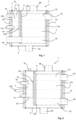
- the plate heat exchanger arrangements 1 presented in Figures 1-3 comprise an outer casing, which is formed of a substantially horizontal cylindrical shell 4 and substantially vertical first and second end plates 5a, 5b.
- a first plate pack 2 and a second plate pack 3 are arranged inside the same common outer casing.
- the first plate pack 2 and the second plate pack 3 are formed by heat exchange plates having two openings and arranged on top of each other, in which plate packs the heat exchange plates are attached to each other as plate pairs, the inner parts of which plate pairs are arranged in connection with each other via flow passages 2a, 2b, 3a, 3b formed by the openings of the heat exchange plates.
- Each plate pack comprises several plate pairs. A number of the plate pairs may vary and a length of the plate pack in a longitudinal direction of the plate pack may differ from each other.
- a diameter of the first plate pack 2, defined by the outer edges of the heat exchange plates, is greater than the diameter of the second plate pack 3.
- the first plate pack 2 and the second plate pack 3 are arranged adjacent to each other and a partition plate 9 is arranged between the plate packs.
- a partition plate 9 has a size which is greater than a size of the plate pack having the greater diameter so that the partition plate is in connection with the inner surface of the outer casing from one edge of the partition plate, and so the partition plate forms multiple passes for heat exchange medium in the shell side of the heat exchanger.
- a partition plate 9 is arranged to at least the whole area of the plate pack having greater diameter.
- an inlet and outlet connections 6a, 6b of the first plate pack 2 is arranged through different end plates 5a, 5b of the outer casing.
- one of the connections 6b is arranged outside of the outer surface of the second plate pack 3 and therefore it can be easily arranged through the end plate 5b of the outer casing.
- the inlet and outlet connections 7a and 7b of the second plate pack 3 and the outlet connection 6b of the first plate pack 2 is arranged through the same end plate 5b. It is possible that the inlet and outlet connections 6a, 6b of the first plate pack 2 are arranged nested and the inner connection pipe elongates at least partly inside the flow channel 2b (not shown in Figure 1 ).
- a heat exchange medium circuit of the first plate pack 2 is formed between the inlet and outlet connections 6a, 6b, a flow direction may be whichever.
- a heat exchange medium circuit of the second plate pack 3 is formed between the inlet and outlet connections 7a and 7b, a flow direction may be whichever.
- an inlet and outlet connections 6a, 6b of the first plate pack 2 are arranged through the same end plate 5a.
- An inlet and outlet connections 7a, 7b of the second plate pack 3 are arranged through other end plate 5b of the outer casing.
- a shell side of plate heat exchanger arrangement comprises one inlet connection 8a and two outlet connections 8b, 8c.
- the shell side comprises two passes, which are formed by a partition plate 9 arranged between the plate packs.
- a plate heat arrangement 1 comprises three plate packs: a first plate pack 2, a second plate pack 3 and a third plate pack 10.
- a diameter of the third plate pack 10, defined by the outer edges of the heat exchange plates, is smaller than the diameter of the first plate pack 2 and the third plate pack 3.
- a diameter of the second plate pack 3 is also smaller than the diameter of the first plate pack 2.
- the plate packs are separated from each other by arranging partition plates 9, 11 between the plate packs.
- the partition plates 9, 11 elongates to the inner surface of the outer casing at one edge of the partition plates and form multiple passes for heat exchange medium in the shell side of the heat exchanger.
- the partition plates 9, 11, cover the whole area of the greater sized plate pack to which they are connected.
- a heat exchange medium circuit of the first plate pack 2 is formed between an inlet and an outlet connections 6a, 6b same kind as in Figure 1 .
- An inlet connection 7a of the second plate pack 3 is arranged inside the outlet connection 7b of the second plate pack, wherein the connections 7a, 7b are nested and the inner connection 7a elongates at least partly inside the flow channel 3b.
- a heat exchange medium circuit of the third plate pack 10 is formed between the inlet and outlet connections 12a, 12b, a flow direction may be whichever.
- the inlet and outlet connections 12a, 12b are connected with the flow channels 10a, 10b of the third plate pack.
- one of the connections of the first plate pack 2 is arranged outside of the outer surface of the second plate pack 3, when the first plate pack has a diameter, defined by the outer edges of the heat exchange plates, which is greater than a diameter of the second plate pack.
- an inlet and outlet connection 7a, 7b of the second plate pack 3 is arranged outside of the outer surface of the third plate pack 10, when the second plate pack has a diameter, defined by the outer edges of the heat exchange plates, which is greater than a diameter of the third plate pack.
- a shell side of plate heat exchanger arrangement comprises one inlet connection 8a and three outlet connections 8b, 8c, 8d.
- the shell side comprises three passes for a heat exchange medium flowing inside the shell, which are formed by a partition plates 9, 11 arranged between the plate packs.
- Outlet connections 8b, 8c, 8d are connected to the shell parts divided by the partition plates 9,11, each part comprises own outlet connection.
- a first plate pack 2 comprises the support end plates 13a, 13b at the ends of the plate pack
- a second plate pack 3 comprises the support end plates 14a, 14b
- a third plate pack 10 comprises the support end plates 15a, 15b.
- the plate heat exchanger arrangements presented in Figures 1 - 3 may form a plate heat exchanger as such or they may be a part of the modular structure.
- the plate heat exchanger arrangement presented in Figures 1 - 3 may be one module of the modular structure, and an end plate 5a forms a partition wall between the arrangement and the second module of the modular structure.
- the plate heat exchanger arrangements presented in Figures 1 - 3 may form a plate heat exchanger as such or they may be a part of the modular structure.
- the plate heat exchanger arrangement presented in Figures 1 - 3 may be one module of the modular structure, and an end plate 5a forms a partition wall between the arrangement and the second module of the modular structure.
Landscapes
- Engineering & Computer Science (AREA)
- Physics & Mathematics (AREA)
- Thermal Sciences (AREA)
- Mechanical Engineering (AREA)
- General Engineering & Computer Science (AREA)
- Heat-Exchange Devices With Radiators And Conduit Assemblies (AREA)
- Details Of Heat-Exchange And Heat-Transfer (AREA)
Description
- The present invention relates to a plate heat exchanger arrangement according to the independent claim presented below. The invention relates also a modular structure comprising a plate heat exchanger arrangement according to the invention.
- Plate and Shell -type plate heat exchangers are composed of a plate pack formed by heat exchange plates and an outer casing surrounding it, functioning as a pressure vessel. A plate pack is made up of several plate pairs. Each plate pair is typically formed of two heat exchange plates that are attached together at least at their outer periphery. Each heat exchange plate has at least two openings for the flow of a heat exchange medium. Adjacent plate pairs are attached to each other by attaching the openings of two adjacent plate pairs to each other. The inner parts of which plate pairs are arranged in connection with each other via flow passages formed by the openings of the heat exchange plates, wherein a primary circuit of the heat exchanger is formed between the openings in the heat exchange plates. A secondary circuit is formed between connections of the outer casing surrounding the plate pack, and they are arranged in connection with the spaces between the plate pairs of the plate pack. A heat exchange medium of the primary side flows in every other plate space and a heat exchange medium of the secondary side in every other plate space.
- In some applications there might be need for several heat exchangers, but a space for the heat exchangers is limited, wherein it may be beneficial if heat exchangers can be arranged as compact as possible.
- The patent publication
EP 2834578 discloses an apparatus according to the preamble ofclaim 1, which comprises an evaporator and a condenser inside one outer casing in such a manner that the evaporator and the condenser are separated from each other by a partition wall. - The patent publication
EP 0740949 discloses a plate-type heat exchanger having an outer casing, which is divided into the independent segments. The patent publicationWO 91/09262 WO 2015/070201 discloses a plate heat exchanger with a plate pack formed of the plurality of the modules having same size. - It is an object of the present invention to provide a compact plate heat exchanger arrangement comprising at least two plate packs inside the same common outer casing and which plate packs have a common shell side.
- It is also an object of the invention to provide a plate heat exchanger arrangement which can be used as a heat exchanger as such, but which can also be utilized in the modular structures.
- Further, it is an object of the invention to provide a plate heat exchanger construction which is easy to manufacture.
- In order to achieve among others the objects presented above, the invention is characterized by what is presented in the characterizing part of the enclosed independent claim. Some preferred embodiments of the invention will be described in the other claims.
- A typical plate heat exchanger arrangement according to the invention is disclosed in
claim 1. - In a typical plate heat exchanger arrangement according to the invention at least two plate packs having different diameters, defined by the outer edges of the heat exchange plates of the plate pack, are arranged adjacent to each other inside the same common outer casing. This arrangement provides more space for arranging inlet and/or outlet connections of the plate packs through the same end plate of the outer casing. Further, when two or more plate packs are arranged inside the same common outer casing, they can divide common shell side in the heat exchanger arrangement. These are advantageous constructions if there is a limited space available for multiple heat exchangers. In a typical embodiment according to the invention the shell side is common in all plate packs of the arrangement. A shell side can be constructed simply without complex structures which e.g. simplify a pipework required for the heat exchanger arrangement according to the invention.
- A typical modular structure according to the invention comprises at least two modules arranged inside the same outer casing, which modules are separated from each other by a partition wall, and at least one module is formed of a plate heat exchanger arrangement according to the present invention comprising at least two plate packs.
- According to an embodiment of the present invention, a structure of the arrangement according to the present invention provides a completely welded plate heat exchanger arrangement and it does not affect the pressure-tightness of the heat exchanger.
- The invention will be described in more detail with reference to appended drawings, in which
- Fig. 1
- shows a plate heat exchanger arrangement according to an embodiment of the present invention with two plate packs arranged inside the same common outer casing,
- Fig. 2
- shows a plate heat exchanger arrangement according to other embodiment of the present invention with two plate packs arranged inside the same common outer casing, and
- Fig. 3
- a plate heat exchanger arrangement according to an embodiment of the present invention with three plate packs arranged inside the same common outer casing.
- A plate heat exchanger arrangement according to the invention comprises at least two plate packs, a first plate pack and a second plate pack, and an outer casing surrounding them. The outer casing comprises a shell and a first end plate and a second end plate, which end plates are arranged at the ends of the shell. In a typical embodiment according to the invention, the shell is a substantially horizontal cylindrical shell and the end plates are vertical end plates. A longitudinal direction of the outer casing or cylindrical shell is the direction between the end plates of the outer casing, typically it means the horizontal direction. If the cylindrical shell of the outer casing is a straight circular cylinder, then its longitudinal direction is the same as the direction of the central axis of the cylinder in question.
- In a plate heat exchanger arrangement according to the present invention, a first plate pack and a second plate pack are formed by heat exchange plates having at least two openings and arranged on top of each other. A plate pack comprises ends at the direction of the heat exchange plates and an outer surface defined by the outer edges of the heat exchange plates. In a preferred embodiment of the invention, both ends of the plate pack comprise a separate support end plate. The plate packs are made up of several plate pairs. Each plate pair is typically formed of two heat exchange plates that are attached together at least at their outer periphery. Each heat exchange plate has at least two openings for a flow of a heat exchange medium. Adjacent plate pairs are attached to each other by attaching the openings of two adjacent plate pairs to each other. The inner parts of which plate pairs are arranged in connection with each other via flow passages formed by the openings of the heat exchange plates. In a plate pack, a heat exchange medium can flow from a plate pair to another via the openings. In an embodiment according to the present invention, heat exchange plates are typically circular heat exchange plates, wherein the plate pack is mainly circular cylinder in shape. A plate pack may also be formed of e.g. semicircle or ellipse heat exchange plates. A longitudinal direction of the plate packs is same as the longitudinal direction of the cylindrical shell.
- A common outer casing surrounds the plate packs arranged adjacent to each other inside the outer casing, preferably a common cylindrical shell surrounds the plate packs. According to the present invention, a first plate pack and a second plate pack are arranged adjacent to each other inside the same common outer casing, and the first plate pack has a diameter, defined by the outer edges of the heat exchange plates, which is greater than a diameter of the second plate pack.
- According to the invention, at least one partition plate is arranged between the first plate pack and the second plate pack. According to the present invention a partition plate, which is arranged in between the adjacent plate packs, has a size which corresponds at least the size of the plate pack having the greater diameter. In the present invention, a partition plate has a size wherein the partition plate is in connection with the inner surface of the outer casing from one edge of the partition plate. The partition plate between the adjacent plate packs makes possible to provide a tight construction with plate packs having a different size, defined by the diameter of the heat exchange plates. In the present invention, a partition plate is arranged to elongate from an outer surface of the plate pack to an inner surface of the shell at one side of the plate pack and so the partition plate forms multiple passes for heat exchange medium in the common shell side of the heat exchanger.
- According to an embodiment of the present invention, a partition plate arranged between the adjacent plate packs has a thickness of about 20 - 100 mm. An intermediate plate will support the structure of the plate packs and improves its pressure resistant.
- According to an embodiment of the present invention, a plate heat exchanger arrangement further comprises a third plate pack, wherein inside the same common outer casing is arranged three plate packs adjacent to each other: a first plate pack, a second plate pack and a third plate pack. A third plate pack is also formed from heat exchange plates having at least two openings and arranged on top of each other, as the first and second plate packs. A third plate pack comprises ends at the direction of the heat exchange plates and an outer surface defined by the outer edges of the heat exchange plates, and the heat exchange plates are attached to each other as plate pairs, the inner parts of which plate pairs are arranged in connection with each other via flow passages formed by the openings of the heat exchange plates. According to an embodiment of the present invention, these three plate packs are arranged adjacent to each other inside the same common outer casing, and at least a first plate pack has a diameter greater than the second plate pack and the third plate pack. According to an embodiment of the present invention, the third plate pack has a diameter, defined by the outer edges of the heat exchange plates, which is at least smaller than a diameter of the first plate pack. According to an embodiment of the present invention, the third plate pack has a diameter, defined by the outer edges of the heat exchange plates, which is smaller than a diameter of the first plate pack and the second plate pack. The plate packs can be arranged adjacent to each other in any order inside the outer casing. According to the present invention, at least one plate pack has a greater diameter than other plate packs. In an embodiment according to the present invention, all plate packs arranged adjacent to each other have a different diameter.
- When a plate heat exchange arrangement comprises three plate packs, the plate heat exchanger arrangement may also comprise a second partition plate arranged between the third plate pack and the plate pack arranged adjacent thereto. A partition plate is corresponding as the partition plate between the first and the second plate packs defined above. A partition plate has a size which corresponds at least the size of the plate pack having the greater diameter. In a typical embodiment, a partition plate has a size wherein the partition plate is in connection with the inner surface of the outer casing from one edge of the partition plate. In an embodiment of the invention comprising three plate packs adjacent to each other, the middle plate pack is between the partition plates and these partition plates may also define flow channel for heat exchange medium flowing inside the common shell side, i.e. these partition plates elongate from an outer surface of the plate pack to an inner surface of the shell at one side of the plate pack. In an embodiment of the invention, a shell side has one common inlet connection, and outlet connections of the shell side are arranged to the spaces between these partition plates.
- A plate heat exchanger arrangement according to the present invention may also comprise more than three plate packs, wherein at least a first plate pack has a diameter greater than other plate packs. The present invention is not only limited to above described arrangements which comprise two or three different sized plate packs. A plate heat exchanger arrangement may also comprise plate packs with similar size, but the present invention is based on at least two different sized plate packs arranged adjacent to each other inside the same common outer casing, and hence providing more space to arrange inlet/outlet connections of the plate pack with the greater diameter to the same end plate of the outer casing as the inlet and outlet connections of the plate pack with smaller diameter.
- The plate packs according to the invention may comprise a different amount of the plate pairs. The plate packs may be dimensioned on the basis of the requirement of an application.
- A plate heat exchanger arrangement according to the invention comprises an inlet connection and an outlet connection for each plate pack, which connections are connected with the flow channels of said plate pack. The primary circuit of the plate pack is thus formed between the inlet and outlet connection of said plate pack. The inlet and outlet connections of the secondary circuit are arranged through the outer casing in connection with the inner side of the outer casing, in the spaces between the plate pairs. Typically, the primary circuits of the plate packs and the secondary circuit are separate from each other, i.e. the heat exchange medium flowing in the inner part of a plate pack cannot get mixed with the heat exchange medium flowing in the outer casing and with the heat exchange medium flowing in the inner part of another plate pack.
- In a plate heat exchanger arrangement of the invention, an inlet and an outlet connection of the first plate pack are arranged to be in connection with the flow passages of the first plate pack. An inlet and outlet connection comprise a connection tube, which is arranged through an end plate of the outer casing and connected with the flow passages of the plate pack. An inlet and outlet connection of the second plate pack, which are arranged to be in connection with the flow passages of the second plate pack, comprises a connection tube, which are arranged through an end plate of the outer casing and connected with the flow passages of the plate pack. Correspondingly, according to an embodiment of the invention a third plate pack comprises an inlet and outlet connections comprising a connection tube, which are arranged through an end plate of the outer casing and connected with the flow passages of the third plate pack.
- The adjacent plate packs with different outer diameters make possible to easily arrange an inlet and/or outlet connection of a greater sized plate pack to through the same end plate of the outer casing as the inlet and outlet connection of a smaller sized plate pack. According to an embodiment of the present invention, an inlet and/or outlet connection of the first plate pack is arranged outside of the outer surface of the second plate pack, when the first plate pack has a diameter, defined by the outer edges of the heat exchange plates, which is greater than a diameter of the second plate pack, and/or an inlet and/or outlet connection of the second plate pack is arranged outside of the outer surface of the third plate pack, when the second plate pack has a diameter, defined by the outer edges of the heat exchange plates, which is greater than a diameter of the third plate pack. In a preferred embodiment of the present invention, an inlet connection and/or an outlet connection of the first plate pack, and an outlet connection and an inlet connection of the second plate pack are arranged through the same end plate, wherein the first plate pack has a diameter, defined by the outer edges of the heat exchange plates, which is greater than a diameter of the second plate pack, and an inlet and/or outlet connection of the first plate pack is arranged outside of the outer surface of the second plate pack. Also, in same manner, in an embodiment of the invention comprising three or more plate packs, an inlet and/or outlet connections of each plate pack are preferably arranged through the same end plate.
- According to an embodiment of the present invention, an inlet connection and an outlet connection of a plate pack comprise a connection pipe, and they are arranged nested, wherein an outer diameter of inner connection pipe is smaller than a diameter of the outer connection pipe and the flow passage of the plate pack. This enables to arrange an inlet and an outlet connection of the plate pack through same end plate of the outer casing and provides more compact structure. When the inlet and outlet connections are arranged nested and connected to one flow channel of the plate pack, an inlet connection of the plate pack is formed by arranging a connection pipe through an outlet connection of the plate pack, wherein said inlet connection pipe elongates inside the flow passage of said plate pack and outlet connection pipe is attached to the end of the plate pack for forming connection to said flow channel.
- According to an embodiment of the present invention a plate heat exchanger arrangement provides a compact structure since the inlet and the outlet connections of the plate packs are possible to arrange through one end plate of the outer casing. This kind of plate heat exchanger arrangement according to the invention can be formed with an openable end plate structure and the plate pack can be easily removed out from the outer casing, if required e.g. for cleaning.
- In a plate heat exchanger arrangement of the invention, an inlet connection and an outlet connection for heat exchange medium flowing inside the shell are arranged through the outer casing, typically through the shell of the outer casing. An inlet and an outlet connection of the shell side may be arranged through the end plate(s) or through the shell, or any combination of them. In the present invention, a single heat exchange medium flows inside in the shell side of the plate heat exchanger arrangement, i.e. the shell side is common in all plate packs. According to an embodiment of the invention, a plate heat exchanger arrangement comprises one inlet connection and two outlet connections for a heat exchange medium flowing in a shell side, when the partition plate between the adjacent plate packs divides a shell part to two separate parts in an edge of the outer casing, each part comprises own outlet connection. In an embodiment according to the invention, where the arrangement comprises three plate packs and two partition plates, a plate heat exchanger arrangement may comprise one inlet connection and three outlet connections for a heat exchange medium flowing in a shell side, each part divided by the partition plate comprises own outlet connection.
- According to an embodiment of the present invention, a separate stopper plate is arranged between an outer surface of a plate pack and an inner surface of the shell at least to one side of the plate pack for forming multiple passes for heat exchange medium in the shell side of the heat exchanger. According to an embodiment of the invention a stopper plate may be welded to a partition plate arranged between the adjacent plate packs. In an embodiment, a stopper plate is a substantially planar in the direction of the heat exchange plates and it is arranged to the plate heat exchanger structure in the direction of the heat exchange plates of the plate pack.
- In a plate heat exchanger according to the present invention the heat exchange mediums may be arranged to flow forward current, counter current or cross flow.
- A plate heat exchanger arrangement according to the invention may be a heat exchanger as such, or it may be a part of the modular structure.
- A modular structure according to the invention comprises at least two modules arranged inside the same outer casing, which modules are separated from each other by a partition wall, and at least one module is formed of a plate heat exchanger arrangement according to invention comprising at least two plate packs. In an embodiment, the outer casing of the modules is continuous in the length of the modular structure. In a modular structure, a partition wall between the plate heat exchanger arrangement and the adjacent module is the end plate of the outer casing of said plate heat exchanger arrangement. The arrangement according to the invention provides a compact modular structure, since at least two plate packs with heat exchange medium circulations can be arranged inside one module part. These kinds of the structures may be advantageous when a space for the heat exchanger applications is limited.
- For the sake of clarity, the same reference numbers are used for corresponding parts in different embodiments.
- The plate
heat exchanger arrangements 1 presented inFigures 1-3 comprise an outer casing, which is formed of a substantially horizontalcylindrical shell 4 and substantially vertical first andsecond end plates - In the
Figures 1 and 2 , afirst plate pack 2 and asecond plate pack 3 are arranged inside the same common outer casing. Thefirst plate pack 2 and thesecond plate pack 3 are formed by heat exchange plates having two openings and arranged on top of each other, in which plate packs the heat exchange plates are attached to each other as plate pairs, the inner parts of which plate pairs are arranged in connection with each other viaflow passages first plate pack 2, defined by the outer edges of the heat exchange plates, is greater than the diameter of thesecond plate pack 3. - The
first plate pack 2 and thesecond plate pack 3 are arranged adjacent to each other and apartition plate 9 is arranged between the plate packs. As shown in Figures, apartition plate 9 has a size which is greater than a size of the plate pack having the greater diameter so that the partition plate is in connection with the inner surface of the outer casing from one edge of the partition plate, and so the partition plate forms multiple passes for heat exchange medium in the shell side of the heat exchanger. Typically, apartition plate 9 is arranged to at least the whole area of the plate pack having greater diameter. - In
Figure 1 , an inlet andoutlet connections first plate pack 2 is arranged throughdifferent end plates Figure 1 , one of theconnections 6b is arranged outside of the outer surface of thesecond plate pack 3 and therefore it can be easily arranged through theend plate 5b of the outer casing. Hence, the inlet andoutlet connections second plate pack 3 and theoutlet connection 6b of thefirst plate pack 2 is arranged through thesame end plate 5b. It is possible that the inlet andoutlet connections first plate pack 2 are arranged nested and the inner connection pipe elongates at least partly inside theflow channel 2b (not shown inFigure 1 ). A heat exchange medium circuit of thefirst plate pack 2 is formed between the inlet andoutlet connections Figure 1 , a heat exchange medium circuit of thesecond plate pack 3 is formed between the inlet andoutlet connections - In
Figure 2 , an inlet andoutlet connections first plate pack 2 are arranged through thesame end plate 5a. An inlet andoutlet connections second plate pack 3 are arranged throughother end plate 5b of the outer casing. - In
Figures 1 and 2 , a shell side of plate heat exchanger arrangement comprises oneinlet connection 8a and twooutlet connections partition plate 9 arranged between the plate packs. - In an embodiment presented in
Figure 3 , aplate heat arrangement 1 comprises three plate packs: afirst plate pack 2, asecond plate pack 3 and athird plate pack 10. A diameter of thethird plate pack 10, defined by the outer edges of the heat exchange plates, is smaller than the diameter of thefirst plate pack 2 and thethird plate pack 3. A diameter of thesecond plate pack 3 is also smaller than the diameter of thefirst plate pack 2. The plate packs are separated from each other by arrangingpartition plates Figure 3 , thepartition plates partition plates first plate pack 2 is formed between an inlet and anoutlet connections Figure 1 . Aninlet connection 7a of thesecond plate pack 3 is arranged inside theoutlet connection 7b of the second plate pack, wherein theconnections inner connection 7a elongates at least partly inside theflow channel 3b. InFigure 3 , a heat exchange medium circuit of thethird plate pack 10 is formed between the inlet andoutlet connections outlet connections flow channels Figure 3 , one of the connections of thefirst plate pack 2 is arranged outside of the outer surface of thesecond plate pack 3, when the first plate pack has a diameter, defined by the outer edges of the heat exchange plates, which is greater than a diameter of the second plate pack. Further, an inlet andoutlet connection second plate pack 3 is arranged outside of the outer surface of thethird plate pack 10, when the second plate pack has a diameter, defined by the outer edges of the heat exchange plates, which is greater than a diameter of the third plate pack. Hence, the inlet or the outlet connection of thefirst plate pack 2, and the outlet and inlet connections of thesecond plate pack 3 and the outlet and inlet connections of thethird plate pack 10 are arranged through thesame end plate 5b of the outer casing. - In
Figure 3 , a shell side of plate heat exchanger arrangement comprises oneinlet connection 8a and threeoutlet connections partition plates Outlet connections partition plates - In Figures, a
first plate pack 2 comprises thesupport end plates second plate pack 3 comprises thesupport end plates third plate pack 10 comprises thesupport end plates 15a, 15b. - The plate heat exchanger arrangements presented in
Figures 1 - 3 may form a plate heat exchanger as such or they may be a part of the modular structure. In modular structures, the plate heat exchanger arrangement presented inFigures 1 - 3 may be one module of the modular structure, and anend plate 5a forms a partition wall between the arrangement and the second module of the modular structure. - The plate heat exchanger arrangements presented in
Figures 1 - 3 may form a plate heat exchanger as such or they may be a part of the modular structure. In modular structures, the plate heat exchanger arrangement presented inFigures 1 - 3 may be one module of the modular structure, and anend plate 5a forms a partition wall between the arrangement and the second module of the modular structure.
Claims (10)
- A plate heat exchanger arrangement (1), which comprises at least- a first plate pack (2), and- a second plate pack (3),
which first plate pack (2) and second plate pack (3) are formed by heat exchange plates having at least two openings and arranged on top of each other, and the heat exchange plates are attached to each other as plate pairs, the inner parts of which plate pairs are arranged in connection with each other via flow passages (2a, 2b, 3a, 3b) formed by the openings of the heat exchange plates, wherein primary circuit of the heat exchanger is formed between the openings in the heat exchange plates,- a common outer casing surrounding the first plate pack (2) and the second plate pack (3), which outer casing comprises a longitudinal cylindrical shell (4) and end plates (5a, 5b) arranged at both ends of the shell,- an inlet and outlet connections (6a, 6b) of the first plate pack, which are connected with the flow passages (2a, 2b) of the first plate pack,- an inlet and outlet connections (7a, 7b) of the second plate pack, which are connected with the flow passages (3a, 3b) of the second plate pack,- an inlet connection (8a) and an outlet connection (8b, 8c) for heat exchange medium flowing inside the shell, which connections are arranged through the outer casing, wherein a secondary circuit is formed between connections of the outer casing arranged in connection with the spaces between the plate pairs of the plate pack,characterized in that the first plate pack (2) and the second plate pack (3) are arranged adjacent to each other inside the common outer casing, and the first plate pack (2) has a diameter, defined by the outer edges of the heat exchange plates, which is greater than a diameter of the second plate pack (3), and at least one partition plate (9) is arranged between the first plate pack (2) and the second plate pack (3), which partition plate (9) has a size which corresponds at least the size of the plate pack having the greater diameter and the partition plate (9) is further arranged to elongate from an outer surface of the plate pack to an inner surface of the shell at one side of the plate pack for forming multiple passes for heat exchange medium in the shell side of the heat exchanger, andwherein the first and the second plate pack has common shell side in the heat exchanger arrangement, wherein a single heat exchange medium is arranged to flow inside in the shell side of the plate heat exchanger arrangement. - The plate heat exchanger arrangement according to claim 1, characterized in that the plate heat exchanger arrangement further comprises a third plate pack (10), which has a diameter, defined by the outer edges of the heat exchange plates, which at least is smaller than a diameter of the first plate pack (2), preferably the plate heat exchanger arrangement comprises a third plate pack (10) having a diameter, which is smaller than a diameter of the first plate pack (2) and the second plate pack (3).
- The plate heat exchanger arrangement according to claim 2, characterized in that the first plate pack, the second plate pack and the third plate pack are arranged adjacent to each other inside the same common outer casing.
- The plate heat exchanger arrangement according to claim 2 or 3, characterized in that the plate heat exchanger arrangement comprises a second partition plate (11) arranged between the third plate pack (10) and the plate pack arranged adjacent thereto.
- The plate heat exchanger arrangement according to any of the claims 1 to 4, characterized in that- the inlet and/or outlet connection (6a, 6b) of the first plate pack (2) is arranged outside of the outer surface of the second plate pack (3).
- The plate heat exchanger arrangement according to any of the claims 2 to 5, characterized in that- the inlet and/or outlet connection (7a, 7b) of the second plate pack (2) is arranged outside of the outer surface of the third plate pack (10).
- The plate heat exchanger arrangement according to any of the preceding claims, characterized in that the inlet and outlet connection (6a, 6b, 7a, 7b, 12a, 12b) of at least one of the plate pack (2, 3, 10) comprise connection pipes, which are arranged nested, wherein an outer diameter of inner connection pipe is smaller than a diameter of the outer connection pipe and the flow passage of the plate pack.
- A modular structure, which comprises at least two modules arranged inside the same outer casing, and which modules are separated from each other by a partition wall, characterized in that at least one module is formed of a plate heat exchanger arrangement according to any of the preceding claims 1 to 7.
- The modular structure according to claim 8, characterised in that the outer casing of the modules is continuous in the length of the modular structure.
- The modular structure according to claim 8 or 9, characterised in that the partition wall between the plate heat exchanger arrangement and the adjacent module is the end plate (5a) of the outer casing of said arrangement (1).
Priority Applications (1)
| Application Number | Priority Date | Filing Date | Title |
|---|---|---|---|
| RS20250158A RS66512B1 (en) | 2020-04-06 | 2021-03-30 | A plate heat exchanger arrangement |
Applications Claiming Priority (2)
| Application Number | Priority Date | Filing Date | Title |
|---|---|---|---|
| FI20205367A FI20205367A1 (en) | 2020-04-06 | 2020-04-06 | PLATE HEAT EXCHANGER ARRANGEMENT |
| PCT/FI2021/050225 WO2021205064A1 (en) | 2020-04-06 | 2021-03-30 | A plate heat exchanger arrangement |
Publications (3)
| Publication Number | Publication Date |
|---|---|
| EP4133232A1 EP4133232A1 (en) | 2023-02-15 |
| EP4133232C0 EP4133232C0 (en) | 2024-11-20 |
| EP4133232B1 true EP4133232B1 (en) | 2024-11-20 |
Family
ID=75438816
Family Applications (1)
| Application Number | Title | Priority Date | Filing Date |
|---|---|---|---|
| EP21717490.3A Active EP4133232B1 (en) | 2020-04-06 | 2021-03-30 | A plate heat exchanger arrangement |
Country Status (9)
| Country | Link |
|---|---|
| US (1) | US12235050B2 (en) |
| EP (1) | EP4133232B1 (en) |
| JP (1) | JP7720323B2 (en) |
| KR (1) | KR20220162703A (en) |
| CN (1) | CN115605721B (en) |
| CA (1) | CA3172661A1 (en) |
| FI (1) | FI20205367A1 (en) |
| RS (1) | RS66512B1 (en) |
| WO (1) | WO2021205064A1 (en) |
Citations (1)
| Publication number | Priority date | Publication date | Assignee | Title |
|---|---|---|---|---|
| EP2834578B1 (en) * | 2012-04-04 | 2016-03-30 | Vahterus Oy | An apparatus for vapourising a medium and separating droplets as well as for condensing the medium |
Family Cites Families (38)
| Publication number | Priority date | Publication date | Assignee | Title |
|---|---|---|---|---|
| US3334399A (en) * | 1962-12-31 | 1967-08-08 | Stewart Warner Corp | Brazed laminated construction and method of fabrication thereof |
| FI84659C (en) | 1989-12-14 | 1991-12-27 | Mauri Eino Olavi Kontu | VAERMEVAEXLARE. |
| DE9204952U1 (en) * | 1991-06-04 | 1992-07-16 | Autokühler GmbH & Co KG, 3520 Hofgeismar | Heat exchangers, especially for condensation dryers |
| FR2733823B1 (en) | 1995-05-04 | 1997-08-01 | Packinox Sa | PLATE HEAT EXCHANGER |
| FI106577B (en) * | 1996-09-04 | 2001-02-28 | Abb Installaatiot Oy | Device for transmitting heating and cooling power |
| SE9700614D0 (en) * | 1997-02-21 | 1997-02-21 | Alfa Laval Ab | Flat heat exchanger for three heat exchanging fluids |
| US5845505A (en) * | 1997-05-30 | 1998-12-08 | American Precision Industries Inc. | Precooler/chiller/reheater heat exchanger for air dryers |
| FR2856747B1 (en) * | 2003-06-25 | 2005-09-23 | Valeo Thermique Moteur Sa | MODULE FOR COOLING EXHAUST AIR AND RECIRCULATED EXHAUST GASES OF AN INTERNAL COMBUSTION ENGINE OF A MOTOR VEHICLE. |
| DE10361519A1 (en) * | 2003-12-23 | 2005-07-28 | Basf Ag | Process for the production of chlorine by gas phase oxidation of hydrogen chloride |
| FR2864582B1 (en) * | 2003-12-24 | 2006-03-17 | Valeo Thermique Moteur Sa | HEAT EXCHANGE MODULE FOR CONTROLLING THE TEMPERATURE OF GASES ADMITTED IN A MOTOR VEHICLE THERMAL MOTOR |
| US7121102B2 (en) * | 2004-06-29 | 2006-10-17 | Api Heat Transfer, Inc. | Precooler/chiller/reheater heat exchanger system for providing warm dried air |
| DK1616610T3 (en) * | 2004-07-13 | 2012-10-22 | Byeong-Seung Lee | Plate heat exchanger with a separation function for condensed fluid and its process |
| MX354600B (en) * | 2005-12-28 | 2018-03-13 | Wabtec Holding Corp | Multi-fluid heat exchanger arrangement. |
| US7753105B2 (en) * | 2006-05-16 | 2010-07-13 | Delphi Technologies, Inc. | Liquid cooled condenser having an integrated heat exchanger |
| DE102006048667A1 (en) * | 2006-10-14 | 2008-04-17 | Modine Manufacturing Co., Racine | Heat exchanger arrangement and method for heat transfer |
| KR101693175B1 (en) * | 2008-01-28 | 2017-01-06 | 프라이무트 요아힘 마롤트 | Multi-passage thermal sheeting and heat exchanger equipped therewith |
| EP2136175B1 (en) * | 2008-06-21 | 2016-06-22 | Joachim Schult | Heat transfer plate, plate pair, plate stack, compact plate heat exchanger and its manufacturing process |
| EP2339280B1 (en) * | 2009-12-24 | 2016-07-13 | Caloperm GmbH | Compact plate heat transfer device |
| EP2377596B9 (en) * | 2010-04-14 | 2016-04-13 | Kaeser Kompressoren Se | Refrigerant type dryer, in particular pressurised air refrigerant type dryer and heat exchanger for a refrigerant type dryer, in particular pressurised air refrigerant type dryer |
| US8881797B2 (en) * | 2010-05-05 | 2014-11-11 | Ametek, Inc. | Compact plate-fin heat exchanger utilizing an integral heat transfer layer |
| US20130294977A1 (en) * | 2010-12-01 | 2013-11-07 | Meggit (Uk) Limited | Apparatus for use in production of nitric acid |
| JP5960955B2 (en) * | 2010-12-03 | 2016-08-02 | 現代自動車株式会社Hyundai Motor Company | Vehicle capacitors |
| US20120247740A1 (en) | 2011-03-31 | 2012-10-04 | Denso International America, Inc. | Nested heat exchangers |
| CN102620581B (en) | 2012-04-01 | 2014-08-13 | 东莞埃欧热能技术有限公司 | a heat exchanger |
| US9021817B2 (en) * | 2012-07-03 | 2015-05-05 | Parker-Hannifin Corporation | Monolithic construction compressed air/gas dryer system with filtration |
| JP2014161777A (en) * | 2013-02-22 | 2014-09-08 | Sumitomo Precision Prod Co Ltd | Catalytic reactor and method for manufacturing a catalytic reactor |
| CN103090708A (en) * | 2013-03-04 | 2013-05-08 | 天津华赛尔传热设备有限公司 | Blast furnace cinder-flushing water heat exchanger |
| US20150129181A1 (en) | 2013-11-11 | 2015-05-14 | Tranter, Inc. | Modular heat exchanger |
| JP6569855B2 (en) | 2015-08-05 | 2019-09-04 | パナソニックIpマネジメント株式会社 | Heat exchanger |
| JP6321067B2 (en) * | 2016-03-31 | 2018-05-09 | 住友精密工業株式会社 | Diffusion bonding type heat exchanger |
| CN105841524A (en) * | 2016-05-29 | 2016-08-10 | 大连格煜科技有限公司 | Multi-stream plate-shell type heat exchange device |
| US10222130B2 (en) * | 2016-08-08 | 2019-03-05 | Caterpillar Inc. | Work machine heat exchanger |
| KR101733934B1 (en) * | 2016-10-26 | 2017-05-08 | 서진욱 | A disk bundle type heat-exchange |
| IT201700119692A1 (en) * | 2017-10-23 | 2019-04-23 | Ceccato Aria Compressa S R L | PERFECTED HEAT EXCHANGER AND AIR DRYING SYSTEM USING THE ABOVE HEAT EXCHANGER |
| CN108332589A (en) * | 2018-03-09 | 2018-07-27 | 苏州市锦翔压力容器制造有限公司 | A kind of spiral heat exchanger of center augmentation of heat transfer |
| RS61922B1 (en) | 2018-10-12 | 2021-06-30 | Vahterus Oy | A plate heat exchanger arrangement |
| WO2021124582A1 (en) * | 2019-12-20 | 2021-06-24 | エム・テクニック株式会社 | Heat exchanger |
| EP4320399A1 (en) * | 2021-04-06 | 2024-02-14 | GKN Hydrogen GmbH | Heat exchanger for controlling the temperature of a solid substance |
-
2020
- 2020-04-06 FI FI20205367A patent/FI20205367A1/en unknown
-
2021
- 2021-03-30 CA CA3172661A patent/CA3172661A1/en active Pending
- 2021-03-30 RS RS20250158A patent/RS66512B1/en unknown
- 2021-03-30 WO PCT/FI2021/050225 patent/WO2021205064A1/en not_active Ceased
- 2021-03-30 JP JP2022561160A patent/JP7720323B2/en active Active
- 2021-03-30 US US17/916,941 patent/US12235050B2/en active Active
- 2021-03-30 EP EP21717490.3A patent/EP4133232B1/en active Active
- 2021-03-30 CN CN202180026381.9A patent/CN115605721B/en active Active
- 2021-03-30 KR KR1020227033520A patent/KR20220162703A/en active Pending
Patent Citations (1)
| Publication number | Priority date | Publication date | Assignee | Title |
|---|---|---|---|---|
| EP2834578B1 (en) * | 2012-04-04 | 2016-03-30 | Vahterus Oy | An apparatus for vapourising a medium and separating droplets as well as for condensing the medium |
Also Published As
| Publication number | Publication date |
|---|---|
| EP4133232A1 (en) | 2023-02-15 |
| US12235050B2 (en) | 2025-02-25 |
| KR20220162703A (en) | 2022-12-08 |
| JP2023521729A (en) | 2023-05-25 |
| FI20205367A1 (en) | 2021-10-07 |
| CN115605721B (en) | 2026-04-14 |
| US20230152042A1 (en) | 2023-05-18 |
| CN115605721A (en) | 2023-01-13 |
| EP4133232C0 (en) | 2024-11-20 |
| CA3172661A1 (en) | 2021-10-14 |
| JP7720323B2 (en) | 2025-08-07 |
| RS66512B1 (en) | 2025-03-31 |
| WO2021205064A1 (en) | 2021-10-14 |
Similar Documents
| Publication | Publication Date | Title |
|---|---|---|
| US6142221A (en) | Three-circuit plate heat exchanger | |
| US6523606B1 (en) | Heat exchanger tube block with multichamber flat tubes | |
| JP6349465B2 (en) | Arc shaped plate heat exchanger | |
| EP2981780B1 (en) | Plate heat exchanger and method for constructing multiple passes in the plate heat exchanger | |
| US20130264031A1 (en) | Heat exchanger with headering system and method for manufacturing same | |
| EP2241849A2 (en) | Micro-channel heat exchanger in the form of a core-type radiator with special return pipe arrangement | |
| JP2006525485A (en) | Heat exchanger core | |
| JP2004183915A (en) | Heat exchanger | |
| US11867468B2 (en) | Plate heat exchanger arrangement | |
| SK64799A3 (en) | Heat-exchanger coil assembly | |
| FI130318B (en) | A shell and tube heat exchanger | |
| US20070006991A1 (en) | Heat exchanger with internal baffle and an external bypass for the baffle | |
| JP2019086278A (en) | Printed circuit board-type heat exchanger having integral structure | |
| CA2342425C (en) | Multiple tube bundle heat exchanger | |
| US12235050B2 (en) | Plate heat exchanger arrangement | |
| EP3819582A1 (en) | Plate-and-shell heat exchanger and a heat transfer plate for a plate-and-shell heat exchanger | |
| US3117559A (en) | Heat exchanger | |
| EP0504990A1 (en) | Heat exchangers for fluids | |
| JP2005249330A (en) | Heat exchanger | |
| CN103930745A (en) | Plate heat exchanger and method for manufacturing of a plate heat exchanger | |
| EP4281724A1 (en) | Tube heat exchanger |
Legal Events
| Date | Code | Title | Description |
|---|---|---|---|
| STAA | Information on the status of an ep patent application or granted ep patent |
Free format text: STATUS: UNKNOWN |
|
| STAA | Information on the status of an ep patent application or granted ep patent |
Free format text: STATUS: THE INTERNATIONAL PUBLICATION HAS BEEN MADE |
|
| PUAI | Public reference made under article 153(3) epc to a published international application that has entered the european phase |
Free format text: ORIGINAL CODE: 0009012 |
|
| STAA | Information on the status of an ep patent application or granted ep patent |
Free format text: STATUS: REQUEST FOR EXAMINATION WAS MADE |
|
| 17P | Request for examination filed |
Effective date: 20221031 |
|
| AK | Designated contracting states |
Kind code of ref document: A1 Designated state(s): AL AT BE BG CH CY CZ DE DK EE ES FI FR GB GR HR HU IE IS IT LI LT LU LV MC MK MT NL NO PL PT RO RS SE SI SK SM TR |
|
| DAV | Request for validation of the european patent (deleted) | ||
| DAX | Request for extension of the european patent (deleted) | ||
| GRAP | Despatch of communication of intention to grant a patent |
Free format text: ORIGINAL CODE: EPIDOSNIGR1 |
|
| STAA | Information on the status of an ep patent application or granted ep patent |
Free format text: STATUS: GRANT OF PATENT IS INTENDED |
|
| INTG | Intention to grant announced |
Effective date: 20240521 |
|
| GRAJ | Information related to disapproval of communication of intention to grant by the applicant or resumption of examination proceedings by the epo deleted |
Free format text: ORIGINAL CODE: EPIDOSDIGR1 |
|
| STAA | Information on the status of an ep patent application or granted ep patent |
Free format text: STATUS: REQUEST FOR EXAMINATION WAS MADE |
|
| GRAP | Despatch of communication of intention to grant a patent |
Free format text: ORIGINAL CODE: EPIDOSNIGR1 |
|
| STAA | Information on the status of an ep patent application or granted ep patent |
Free format text: STATUS: GRANT OF PATENT IS INTENDED |
|
| INTC | Intention to grant announced (deleted) | ||
| GRAS | Grant fee paid |
Free format text: ORIGINAL CODE: EPIDOSNIGR3 |
|
| GRAA | (expected) grant |
Free format text: ORIGINAL CODE: 0009210 |
|
| STAA | Information on the status of an ep patent application or granted ep patent |
Free format text: STATUS: THE PATENT HAS BEEN GRANTED |
|
| INTG | Intention to grant announced |
Effective date: 20240927 |
|
| AK | Designated contracting states |
Kind code of ref document: B1 Designated state(s): AL AT BE BG CH CY CZ DE DK EE ES FI FR GB GR HR HU IE IS IT LI LT LU LV MC MK MT NL NO PL PT RO RS SE SI SK SM TR |
|
| REG | Reference to a national code |
Ref country code: GB Ref legal event code: FG4D |
|
| REG | Reference to a national code |
Ref country code: CH Ref legal event code: EP |
|
| REG | Reference to a national code |
Ref country code: DE Ref legal event code: R096 Ref document number: 602021022082 Country of ref document: DE |
|
| REG | Reference to a national code |
Ref country code: IE Ref legal event code: FG4D |
|
| U01 | Request for unitary effect filed |
Effective date: 20241120 |
|
| U07 | Unitary effect registered |
Designated state(s): AT BE BG DE DK EE FI FR IT LT LU LV MT NL PT RO SE SI Effective date: 20241127 |
|
| PG25 | Lapsed in a contracting state [announced via postgrant information from national office to epo] |
Ref country code: IS Free format text: LAPSE BECAUSE OF FAILURE TO SUBMIT A TRANSLATION OF THE DESCRIPTION OR TO PAY THE FEE WITHIN THE PRESCRIBED TIME-LIMIT Effective date: 20250320 Ref country code: HR Free format text: LAPSE BECAUSE OF FAILURE TO SUBMIT A TRANSLATION OF THE DESCRIPTION OR TO PAY THE FEE WITHIN THE PRESCRIBED TIME-LIMIT Effective date: 20241120 |
|
| PG25 | Lapsed in a contracting state [announced via postgrant information from national office to epo] |
Ref country code: ES Free format text: LAPSE BECAUSE OF FAILURE TO SUBMIT A TRANSLATION OF THE DESCRIPTION OR TO PAY THE FEE WITHIN THE PRESCRIBED TIME-LIMIT Effective date: 20241120 |
|
| PG25 | Lapsed in a contracting state [announced via postgrant information from national office to epo] |
Ref country code: NO Free format text: LAPSE BECAUSE OF FAILURE TO SUBMIT A TRANSLATION OF THE DESCRIPTION OR TO PAY THE FEE WITHIN THE PRESCRIBED TIME-LIMIT Effective date: 20250220 |
|
| U20 | Renewal fee for the european patent with unitary effect paid |
Year of fee payment: 5 Effective date: 20250317 |
|
| PG25 | Lapsed in a contracting state [announced via postgrant information from national office to epo] |
Ref country code: GR Free format text: LAPSE BECAUSE OF FAILURE TO SUBMIT A TRANSLATION OF THE DESCRIPTION OR TO PAY THE FEE WITHIN THE PRESCRIBED TIME-LIMIT Effective date: 20250221 |
|
| PG25 | Lapsed in a contracting state [announced via postgrant information from national office to epo] |
Ref country code: PL Free format text: LAPSE BECAUSE OF FAILURE TO SUBMIT A TRANSLATION OF THE DESCRIPTION OR TO PAY THE FEE WITHIN THE PRESCRIBED TIME-LIMIT Effective date: 20241120 |
|
| PG25 | Lapsed in a contracting state [announced via postgrant information from national office to epo] |
Ref country code: SM Free format text: LAPSE BECAUSE OF FAILURE TO SUBMIT A TRANSLATION OF THE DESCRIPTION OR TO PAY THE FEE WITHIN THE PRESCRIBED TIME-LIMIT Effective date: 20241120 |
|
| PG25 | Lapsed in a contracting state [announced via postgrant information from national office to epo] |
Ref country code: SK Free format text: LAPSE BECAUSE OF FAILURE TO SUBMIT A TRANSLATION OF THE DESCRIPTION OR TO PAY THE FEE WITHIN THE PRESCRIBED TIME-LIMIT Effective date: 20241120 |
|
| PG25 | Lapsed in a contracting state [announced via postgrant information from national office to epo] |
Ref country code: CZ Free format text: LAPSE BECAUSE OF FAILURE TO SUBMIT A TRANSLATION OF THE DESCRIPTION OR TO PAY THE FEE WITHIN THE PRESCRIBED TIME-LIMIT Effective date: 20241120 |
|
| PLBE | No opposition filed within time limit |
Free format text: ORIGINAL CODE: 0009261 |
|
| STAA | Information on the status of an ep patent application or granted ep patent |
Free format text: STATUS: NO OPPOSITION FILED WITHIN TIME LIMIT |
|
| PG25 | Lapsed in a contracting state [announced via postgrant information from national office to epo] |
Ref country code: MC Free format text: LAPSE BECAUSE OF FAILURE TO SUBMIT A TRANSLATION OF THE DESCRIPTION OR TO PAY THE FEE WITHIN THE PRESCRIBED TIME-LIMIT Effective date: 20241120 |
|
| 26N | No opposition filed |
Effective date: 20250821 |
|
| REG | Reference to a national code |
Ref country code: CH Ref legal event code: H13 Free format text: ST27 STATUS EVENT CODE: U-0-0-H10-H13 (AS PROVIDED BY THE NATIONAL OFFICE) Effective date: 20251023 |
|
| GBPC | Gb: european patent ceased through non-payment of renewal fee |
Effective date: 20250330 |
|
| PG25 | Lapsed in a contracting state [announced via postgrant information from national office to epo] |
Ref country code: GB Free format text: LAPSE BECAUSE OF NON-PAYMENT OF DUE FEES Effective date: 20250330 |
|
| PG25 | Lapsed in a contracting state [announced via postgrant information from national office to epo] |
Ref country code: CH Free format text: LAPSE BECAUSE OF NON-PAYMENT OF DUE FEES Effective date: 20250331 |
|
| PG25 | Lapsed in a contracting state [announced via postgrant information from national office to epo] |
Ref country code: IE Free format text: LAPSE BECAUSE OF NON-PAYMENT OF DUE FEES Effective date: 20250330 |
|
| U20 | Renewal fee for the european patent with unitary effect paid |
Year of fee payment: 6 Effective date: 20260311 |
|
| PGFP | Annual fee paid to national office [announced via postgrant information from national office to epo] |
Ref country code: RS Payment date: 20260303 Year of fee payment: 6 |