EP4132753B1 - System and method for automated assembly of components - Google Patents
System and method for automated assembly of components Download PDFInfo
- Publication number
- EP4132753B1 EP4132753B1 EP21784404.2A EP21784404A EP4132753B1 EP 4132753 B1 EP4132753 B1 EP 4132753B1 EP 21784404 A EP21784404 A EP 21784404A EP 4132753 B1 EP4132753 B1 EP 4132753B1
- Authority
- EP
- European Patent Office
- Prior art keywords
- component
- shaft
- tool
- manipulator
- supported
- Prior art date
- Legal status (The legal status is an assumption and is not a legal conclusion. Google has not performed a legal analysis and makes no representation as to the accuracy of the status listed.)
- Active
Links
Images



Classifications
-
- B—PERFORMING OPERATIONS; TRANSPORTING
- B62—LAND VEHICLES FOR TRAVELLING OTHERWISE THAN ON RAILS
- B62D—MOTOR VEHICLES; TRAILERS
- B62D65/00—Designing, manufacturing, e.g. assembling, facilitating disassembly, or structurally modifying motor vehicles or trailers, not otherwise provided for
- B62D65/02—Joining sub-units or components to, or positioning sub-units or components with respect to, body shell or other sub-units or components
- B62D65/024—Positioning of sub-units or components with respect to body shell or other sub-units or components
-
- B—PERFORMING OPERATIONS; TRANSPORTING
- B25—HAND TOOLS; PORTABLE POWER-DRIVEN TOOLS; MANIPULATORS
- B25J—MANIPULATORS; CHAMBERS PROVIDED WITH MANIPULATION DEVICES
- B25J15/00—Gripping heads and other end effectors
- B25J15/0052—Gripping heads and other end effectors multiple gripper units or multiple end effectors
- B25J15/0061—Gripping heads and other end effectors multiple gripper units or multiple end effectors mounted on a modular gripping structure
-
- B—PERFORMING OPERATIONS; TRANSPORTING
- B25—HAND TOOLS; PORTABLE POWER-DRIVEN TOOLS; MANIPULATORS
- B25J—MANIPULATORS; CHAMBERS PROVIDED WITH MANIPULATION DEVICES
- B25J9/00—Program-controlled manipulators
- B25J9/003—Program-controlled manipulators having parallel kinematics
- B25J9/0033—Program-controlled manipulators having parallel kinematics with kinematics chains having a prismatic joint at the base
-
- B—PERFORMING OPERATIONS; TRANSPORTING
- B62—LAND VEHICLES FOR TRAVELLING OTHERWISE THAN ON RAILS
- B62D—MOTOR VEHICLES; TRAILERS
- B62D65/00—Designing, manufacturing, e.g. assembling, facilitating disassembly, or structurally modifying motor vehicles or trailers, not otherwise provided for
- B62D65/02—Joining sub-units or components to, or positioning sub-units or components with respect to, body shell or other sub-units or components
- B62D65/06—Joining sub-units or components to, or positioning sub-units or components with respect to, body shell or other sub-units or components the sub-units or components being doors, windows, openable roofs, lids, bonnets, or weather strips or seals therefor
-
- B—PERFORMING OPERATIONS; TRANSPORTING
- B65—CONVEYING; PACKING; STORING; HANDLING THIN OR FILAMENTARY MATERIAL
- B65G—TRANSPORT OR STORAGE DEVICES, e.g. CONVEYORS FOR LOADING OR TIPPING, SHOP CONVEYOR SYSTEMS OR PNEUMATIC TUBE CONVEYORS
- B65G47/00—Article or material-handling devices associated with conveyors; Methods employing such devices
- B65G47/74—Feeding, transfer, or discharging devices of particular kinds or types
- B65G47/90—Devices for picking-up and depositing articles or materials
- B65G47/91—Devices for picking-up and depositing articles or materials incorporating pneumatic, e.g. suction, grippers
- B65G47/914—Devices for picking-up and depositing articles or materials incorporating pneumatic, e.g. suction, grippers provided with drive systems incorporating rotary and rectilinear movements
-
- B—PERFORMING OPERATIONS; TRANSPORTING
- B65—CONVEYING; PACKING; STORING; HANDLING THIN OR FILAMENTARY MATERIAL
- B65G—TRANSPORT OR STORAGE DEVICES, e.g. CONVEYORS FOR LOADING OR TIPPING, SHOP CONVEYOR SYSTEMS OR PNEUMATIC TUBE CONVEYORS
- B65G47/00—Article or material-handling devices associated with conveyors; Methods employing such devices
- B65G47/74—Feeding, transfer, or discharging devices of particular kinds or types
- B65G47/90—Devices for picking-up and depositing articles or materials
- B65G47/91—Devices for picking-up and depositing articles or materials incorporating pneumatic, e.g. suction, grippers
- B65G47/918—Devices for picking-up and depositing articles or materials incorporating pneumatic, e.g. suction, grippers with at least two picking-up heads
-
- B—PERFORMING OPERATIONS; TRANSPORTING
- B25—HAND TOOLS; PORTABLE POWER-DRIVEN TOOLS; MANIPULATORS
- B25J—MANIPULATORS; CHAMBERS PROVIDED WITH MANIPULATION DEVICES
- B25J15/00—Gripping heads and other end effectors
- B25J15/06—Gripping heads and other end effectors with vacuum or magnetic holding means
- B25J15/0616—Gripping heads and other end effectors with vacuum or magnetic holding means with vacuum
-
- B—PERFORMING OPERATIONS; TRANSPORTING
- B65—CONVEYING; PACKING; STORING; HANDLING THIN OR FILAMENTARY MATERIAL
- B65G—TRANSPORT OR STORAGE DEVICES, e.g. CONVEYORS FOR LOADING OR TIPPING, SHOP CONVEYOR SYSTEMS OR PNEUMATIC TUBE CONVEYORS
- B65G2811/00—Indexing codes relating to common features for more than one conveyor kind or type
- B65G2811/06—Devices controlling the relative position of articles
- B65G2811/0647—Changing the direction of movement of articles or bulk material
- B65G2811/0663—Pick-up means
Definitions
- the present invention relates generally to automated manufacturing systems and, more particularly, to a system and method for automated assembly of components.
- Automation plays an ever-increasing role in the manufacturing and assembly of products.
- manufacturing systems become more and more automated, there is a corresponding increased use of robotic manipulators to fabricate, process, and assemble components and sub-assemblies into end products.
- One example of such automated manufacturing systems can be found in the automotive industry, where automated manufacturing lines assemble completed vehicles from component parts.
- Many automated manufacturing systems utilize assembly lines having multi-axis robotic manipulators cooperating in a coordinated manner to process and assemble components into a desired end product.
- these multi-axis robotic manipulators comprise a plurality of serially arranged links that are moved by motors to perform the processing and assembly functions.
- a hand for parallel link robot includes: a holder configured to extract a workpiece from an extraction portion and hold the workpiece; and a swing-up mechanism portion configured to swing the workpiece held by the holder up centering around a turning axis to change a posture of the workpiece, and a parallel link robot includes: a link mechanism portion; and the hand mounted to the link mechanism portion.
- a workpiece conveyor that conveys a workpiece includes chucks that hold a workpiece, and a movable body that supports the chucks and is movable in an X direction along first and second guides, which are disposed in parallel or substantially parallel spaced apart from each other, and the movable body includes a first structure guided by the first guide, a second structure guided by the second guide, and a joint that is provided between the first structure and the second structure, and allows one of the first structure and the second structure to swing with respect to the other about an axis of a swing shaft set parallel or substantially parallel to the X direction.
- a device for harvesting mushrooms from a mushroom bed involves a robotic aim configured to interchangeably deploy one of a plurality of different suction grippers, each of the suction grippers having a suction cup having a size and shape profile appropriate for gripping a cap of a mushroom, the cap having a size and shape profile within a predetermined range.
- the present invention provides a system and associated method for the automated assembly of components to a workpiece on an assembly line.
- an exemplary system for automatically handling components to be assembled onto a product on an assembly line includes a carriage supported on a frame that positions the system adjacent the assembly line.
- the carriage is movable to and between a first, retracted position spaced a distance away from the assembly line, and a second, work position displaced from the retracted position in a direction toward the assembly line.
- the carriage supports a multi-axis articulating manipulator that, in turn, supports a component mounting tool configured to receive and support at least one component for assembly to the product.
- the manipulator may be arranged in a first orientation when the carriage is in the first position, and may be pivoted to a second orientation when the carriage is in the second position such that a component on the component mounting tool is supported in a pose for processing when the carriage is in the first position, and the component is supported in a pose for joining to the product when the carriage is in the second position.
- a method of handling components to be assembled to a product on an assembly line includes receiving the component on a component mounting tool at a first, retracted position spaced from the assembly line, and moving the component mounting tool in a direction toward the assembly line to a second, work position.
- the component mounting tool In the first position, the component mounting tool is in a first pose adapted to facilitate receiving or processing the component.
- In the second position, the component mounting tool In the second position, the component mounting tool is in a second pose adapted to facilitate joining the component to the product.
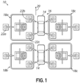
- FIG. 1 depicts an exemplary manufacturing plant 10 including an exemplary system 12 for automatically handling components to be assembled onto a workpiece 14 that is moved along a manufacturing assembly line 16 in accordance with the principles of the present disclosure.
- the manufacturing plant 10 comprises a plurality of individual manufacturing cells 18a, 18b, 18c, 18d positioned adjacent the manufacturing assembly line 16 and disposed on either side of the assembly line 16.
- the assembly line 16 may include conveying structure (not shown) for automated movement of workpieces 14 along the assembly line 16 (such as in the direction of arrow 20), whereby the workpieces 14 may be positioned adjacent the plurality of manufacturing cells 18a - 18d and automated systems, such as robotic manipulators, assemble components onto the workpieces 14 or process the workpieces 14 as part of the manufacturing process.
- the workpieces 14 are depicted as automotive vehicles, and the cells 18a - 18d of the manufacturing plant 10 are configured to assemble components onto the vehicle body or to perform various processing steps which may be desired. While the exemplary embodiment is shown and described herein as a manufacturing plant 10 with cells 18a - 18d adapted to assemble and process vehicles, it will be appreciated that the manufacturing plant 10 and cells 18a - 18d may alternatively be configured to produce various other products.
- an exemplary manufacturing cell 18a may include an exemplary component handling system 12 in accordance with the principles of the present disclosure.
- the component handling system 12 may be arranged in the cell 18a adjacent a plurality of robotic manipulators.
- a first robotic manipulator 22a may be configured to pick one or more components from a supply (not shown) and position the components on or within the component handling system 12.
- the first robotic manipulator 22a may be situated within the manufacturing cell 18a or, alternatively, may be placed adjacent the manufacturing cell 18a and may be configured to extend within the manufacturing cell 18a in cooperation with the component handling system 12.
- Additional robotic manipulators 22b, 22c may be positioned within the cell 18a and may be configured to cooperate with the component handling system 12 to facilitate the assembly of and/or processing of components that are positioned by the component handling system 12 for assembly onto the workpiece 14. While the exemplary manufacturing cell 18a has been shown and described herein as including several robotic manipulators 22a, 22b, 22c which cooperate with the component handling system 12, it will be appreciated that various other configurations of manufacturing cells may alternatively be used.
- the component handling system 12 may be supported on a frame 30 for location within a manufacturing cell 18a and adjacent the manufacturing line 16.
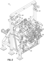
- the exemplary component handling system 12 includes a multi-axis articulating manipulator 32 supported on the frame 30 by a carriage 34.
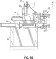
- the carriage 34 is supported on the frame 30 for movement to and between a first, retracted position that is spaced a distance away from the assembly line, as depicted in FIG.
- the carriage 34 is selectively moved between the first and second positions by an actuator 26 having an extendable rod 28. It will be appreciated, however, that various other mechanisms suitable for moving the carriage 34 between the first and second positions may be used.
- the exemplary component handling system 12 further includes a component mounting tool 36 coupled with the multi-axis manipulator 32 and configured to receive and support at least one component 38 for assembly to the workpiece 14.
- the component 38 is illustrated as a door that is to be mounted to the vehicle body as the vehicle body moves along the assembly line 16 and is positioned adjacent the manufacturing cell 18a. While the component 38 is shown and described herein as a vehicle door, it will be appreciated that, in other embodiments, various other components may be received on the component mounting tool 36 for processing and/or assembly onto a workpiece.
- automotive components such as body panels, handles, or hinges, or even non-automotive components, may be received and supported on a component mounting tool in accordance with the principles of the present disclosure.
- the mounting tool 36 when the carriage 34 is in the first, retracted position, the mounting tool 36 is oriented and positioned to receive a component 38, and supports the component 38 in a pose that facilitates further processing of the component 38, such as by a robotic manipulator 22a positioned adjacent the component handling system 12.
- the component 38 in the form of a vehicle door, may be supported with an interior side of the door facing up to thereby facilitate the positioning and attachment of sub-components onto the door.
- the first position of the carriage 34 facilitates the loading and processing of components and sub-components while the workpiece 14 is moving between the manufacturing cells 18a - 18d of the manufacturing assembly line 16, thereby providing increased efficiencies of throughput.
- the mounting tool 36 is moved in translation with the carriage 34, and is also moved in a curvilinear manner such that the mounting tool 36 supports the component 38 in a second pose that facilitates joining the component 38 to the workpiece 14.
- the component 38 may be supported in a generally vertical orientation of the door corresponding to how the door will be attached to the vehicle body (workpiece 14).
- the component handling system 12 may additionally be provided with various sensors for monitoring and facilitating the operation of the component handling system 12.
- the system 12 may further include one or more optical sensors, or cameras 40 positioned at various suitable locations on or near the manipulator 32, the carriage 34, and/or the component mounting tool 36.
- the optical sensors 40 may be supported on a separate support frame 42, for example, or may be coupled with the frame 30 or other structure as may be desired.
- Other sensors may include, as a non-limiting examples, one or more non-contact proximity sensors 44 positioned on or near the component handling system 12 and configured to sense the presence of a workpiece 14 adjacent the component handling system 12. Other sensors may be used to confirm the presence and/or pose of a component supported on the component mounting tool 36. Signals or data obtained from the sensors 40, 44 may be provided to a controller or other suitable computer and used to control and/or monitor operation of the component handling system 12.
- the exemplary multi-axis articulating manipulator 32 will be described in more detail.
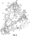
- the manipulator 32 includes a base assembly 50 coupling the manipulator 32 to the carriage 34 for movement with the carriage 34 between the first and second positions on the frame 30.
- a plurality of linkages 52 are coupled with a base plate 54 of the base assembly 50 and are configured to support a tool mounting plate 56 on their opposite ends for coupling with the component mounting tool 36.
- the manipulator 32 includes three fixed-length linkages 52 coupled at their first ends 58 to the base plate 54, and the second ends 60 of the linkages 52 are coupled with the tool mounting plate 56.
- the first ends 58 of the linkages 58 are coupled to the base plate 54 by respective pivot joints 62 and at least one actuator configured to move the second ends 60 of the linkages 52 in a controllable manner. Through coordinated movement of the second ends 60 of the linkages 52, the pose (position and orientation) of the tool mounting plate 56 may be precisely controlled.
- the first end 58 of each linkage 52 is coupled to the base plate 54 by a pair of linear actuators 66a, 66b that are aligned to control movement of the first ends 58 of the linkages 52 in respective first and second directions 68, 70 arranged orthogonal to one another.
- the second ends 60 of the linkages 52 are coupled to the tool mounting plate 56 by respective swivel joints 72 such that the pose of the tool mounting plate 56 may be controlled by selective positioning of the linear actuators 66a, 66b coupled with the respective linkages 52.
- the multi-axis manipulator 32 facilitates precise positioning of a component 38 supported by the component mounting tool 36 that is coupled with the tool mounting plate 56 when the carriage 34 is in the second position.
- the base plate 54 of the multi-axis manipulator 32 When the carriage 34 is in the first position as shown in FIG. 3A , the base plate 54 of the multi-axis manipulator 32 is oriented such that the component mounting tool 36 coupled with tool mounting plate 56 is in the pose described above for receiving and supporting a component 38. As the carriage is moved from the first position to the second position, the base plate 54 pivots to an orientation such that the component mounting tool 36 coupled with tool mounting plate 56 is moved to the pose described above for joining the component 38 to the workpiece 14, as depicted in FIGS. 2 and 3B .
- multi-axis manipulator 32 has been shown and described herein as including three, fixed-length linkages 52, and linear actuators 66a, 66b coupling the linkages 52 to the manipulator base plate 54, it will be appreciated that various other arrangements of linkages and actuators, including variable length linkages, may alternatively be used to facilitate positioning the tool mounting plate 56 at a desired pose for mounting a component 38 to a workpiece 14.
- the component mounting tool 36 includes a tool frame 80 configured to be coupled with the tool mounting plate 56 of the multi-axis manipulator 32.
- One or more shaft assemblies 82a, 82b are supported on the tool frame 80 and, in turn, support gripping members 84 configured to engage and support components 38 to be installed to the workpiece 14.
- the mounting tool 36 includes first and second shaft assemblies 82a, 82b supported on the tool frame 80.
- Each shaft assembly 82a, 82b includes a shaft 86a, 86b supported for rotation relative to the tool frame 80 by respective trunnion mounts 88.
- Each shaft 86a, 86b may further include a plurality of gripping members 84 positioned at spaced-apart circumferential positions around the shaft 86.
- each gripping member 84 may be configured to engage components having different geometries, whereby certain ones of the gripping members 84 may be selectively positioned for engagement with components 38 to be assembled to the workpiece 14 by rotating the shafts 86 about their respective longitudinal axes 90a, 90b relative to the frame 80.
- the component mounting tool 36 may further include a locking assembly 92 cooperating with the one or more of the shaft assemblies 82a, 82b to lock the shafts 86a, 86b at desired rotational positions so that selected gripping members 84 may be positioned for engagement with a component 38.
- the locking assembly 92 includes an actuator 94 having an extendable rod 96 that engages an associated shaft assembly 82a, 82b to thereby lock the respective shaft 86a, 86b in a desired rotational position.
- each shaft assembly 82a, 82b further includes a registration block 98 supported on the shaft 86a, 86b and having registration features configured to cooperate with the rod 96 of the locking assembly actuator 94.
- the distal end 100 of the rod 96 has a wedge-shaped tip, and the registration features on the registration block comprise correspondingly shaped notches 102 disposed at selected angular positions around the shaft 86a, 86b.
- the rod 96 of the locking assembly actuator 94 may be extended to engage the corresponding notch 102 provided on the registration block 98, thereby preventing further rotation of the shaft 86a, 86b.
- component mounting tool 36 has been shown and described herein as comprising two shaft assemblies 82a, 82b, each having a plurality of gripping members 84 disposed at spaced-apart circumferential positions, it will be appreciated that a component mounting tool in accordance with the present disclosure may alternatively comprise only a single shaft assembly, or may include more than two shaft assemblies. Moreover, when only a single type of component will be handled by the component mounting tool 36, or when the components have sufficiently uniform geometries, the component mounting tool 36 may not require a plurality of different gripping members 84 disposed circumferentially around the shaft assemblies 82a, 82b.
- each shaft 86a, 86b includes at least one air passage 120a, 120b, 120c, 120d through the shaft 86a, 86b and configured to provide selective communication between the vacuum pressure source and the respective vacuum bores 118 of the air handlers, such as via respective hoses (not shown) for example.
Landscapes
- Engineering & Computer Science (AREA)
- Mechanical Engineering (AREA)
- Robotics (AREA)
- Manufacturing & Machinery (AREA)
- Chemical & Material Sciences (AREA)
- Combustion & Propulsion (AREA)
- Transportation (AREA)
- Automatic Assembly (AREA)
- Manipulator (AREA)
Description
- .
- The present invention relates generally to automated manufacturing systems and, more particularly, to a system and method for automated assembly of components.
- Automation plays an ever-increasing role in the manufacturing and assembly of products. As manufacturing systems become more and more automated, there is a corresponding increased use of robotic manipulators to fabricate, process, and assemble components and sub-assemblies into end products. One example of such automated manufacturing systems can be found in the automotive industry, where automated manufacturing lines assemble completed vehicles from component parts. Many automated manufacturing systems utilize assembly lines having multi-axis robotic manipulators cooperating in a coordinated manner to process and assemble components into a desired end product. Typically, these multi-axis robotic manipulators comprise a plurality of serially arranged links that are moved by motors to perform the processing and assembly functions.
- As these manufacturing systems have become more automated, the tolerances between assembled components have become smaller and smaller. While conventional six degree-of-freedom manipulators provide flexibility needed for these highly automated manufacturing systems, the configuration of robotic manipulators with serially arranged links results in looser tolerances in the assembled components, or requires that the robotic manipulators are frequently calibrated to ensure that close tolerances can be achieved and maintained. Accordingly, there is a need for improved automated systems that facilitate quick, efficient, and repeatable assembly of components into end products, and which overcome these and other drawbacks of current automated manufacturing systems.
According toUS 2015/209964 A1 a hand for parallel link robot includes: a holder configured to extract a workpiece from an extraction portion and hold the workpiece; and a swing-up mechanism portion configured to swing the workpiece held by the holder up centering around a turning axis to change a posture of the workpiece, and a parallel link robot includes: a link mechanism portion; and the hand mounted to the link mechanism portion.
According toUS 2016/039062 A1 a workpiece conveyor that conveys a workpiece includes chucks that hold a workpiece, and a movable body that supports the chucks and is movable in an X direction along first and second guides, which are disposed in parallel or substantially parallel spaced apart from each other, and the movable body includes a first structure guided by the first guide, a second structure guided by the second guide, and a joint that is provided between the first structure and the second structure, and allows one of the first structure and the second structure to swing with respect to the other about an axis of a swing shaft set parallel or substantially parallel to the X direction.
According toUS2017/265392 A1 a device for harvesting mushrooms from a mushroom bed involves a robotic aim configured to interchangeably deploy one of a plurality of different suction grippers, each of the suction grippers having a suction cup having a size and shape profile appropriate for gripping a cap of a mushroom, the cap having a size and shape profile within a predetermined range. - The present invention provides a system and associated method for the automated assembly of components to a workpiece on an assembly line.
- In one aspect, an exemplary system for automatically handling components to be assembled onto a product on an assembly line includes a carriage supported on a frame that positions the system adjacent the assembly line. The carriage is movable to and between a first, retracted position spaced a distance away from the assembly line, and a second, work position displaced from the retracted position in a direction toward the assembly line. The carriage supports a multi-axis articulating manipulator that, in turn, supports a component mounting tool configured to receive and support at least one component for assembly to the product. The manipulator may be arranged in a first orientation when the carriage is in the first position, and may be pivoted to a second orientation when the carriage is in the second position such that a component on the component mounting tool is supported in a pose for processing when the carriage is in the first position, and the component is supported in a pose for joining to the product when the carriage is in the second position.
- In another aspect, a method of handling components to be assembled to a product on an assembly line includes receiving the component on a component mounting tool at a first, retracted position spaced from the assembly line, and moving the component mounting tool in a direction toward the assembly line to a second, work position. In the first position, the component mounting tool is in a first pose adapted to facilitate receiving or processing the component. In the second position, the component mounting tool is in a second pose adapted to facilitate joining the component to the product.
- The accompanying drawings illustrate exemplary embodiments of the invention and, together with a general description of the invention given above, and the detailed description given below, serve to explain the principles of the invention.
-
FIG. 1 is a schematic plan view of an exemplary manufacturing plant including a system for handling components in accordance with the principles of the present disclosure. -
FIG. 2 is a perspective view of an exemplary system for handling components in accordance with the principles of the present disclosure. -
FIG. 3A is a partial elevation view of the system ofFIG. 2 , illustrating a carriage supported in a first, retracted position. -
FIG. 3B is a partial elevation view, similar toFIG. 3A , and illustrating the carriage in a second position. -
FIG. 4 is a detail perspective view of an exemplary multi-axis articulating manipulator in the system ofFIG. 2 in accordance with the principles of the present disclosure. -
FIG. 5 is a detail perspective view of an exemplary component mounting tool in the system ofFIG. 2 in accordance with the principles of the present disclosure. -
FIG. 6 is a cross-sectional view of the component mounting tool ofFIG. 5 , taken along line 6-6. -
FIG. 1 depicts anexemplary manufacturing plant 10 including anexemplary system 12 for automatically handling components to be assembled onto aworkpiece 14 that is moved along amanufacturing assembly line 16 in accordance with the principles of the present disclosure. In the embodiment shown, themanufacturing plant 10 comprises a plurality ofindividual manufacturing cells manufacturing assembly line 16 and disposed on either side of theassembly line 16. Theassembly line 16 may include conveying structure (not shown) for automated movement ofworkpieces 14 along the assembly line 16 (such as in the direction of arrow 20), whereby theworkpieces 14 may be positioned adjacent the plurality ofmanufacturing cells 18a - 18d and automated systems, such as robotic manipulators, assemble components onto theworkpieces 14 or process theworkpieces 14 as part of the manufacturing process. In the embodiment shown, theworkpieces 14 are depicted as automotive vehicles, and thecells 18a - 18d of themanufacturing plant 10 are configured to assemble components onto the vehicle body or to perform various processing steps which may be desired. While the exemplary embodiment is shown and described herein as amanufacturing plant 10 withcells 18a - 18d adapted to assemble and process vehicles, it will be appreciated that themanufacturing plant 10 andcells 18a - 18d may alternatively be configured to produce various other products. - With continued reference to
FIG. 1 , anexemplary manufacturing cell 18a may include an exemplarycomponent handling system 12 in accordance with the principles of the present disclosure. Thecomponent handling system 12 may be arranged in thecell 18a adjacent a plurality of robotic manipulators. For example, a firstrobotic manipulator 22a may be configured to pick one or more components from a supply (not shown) and position the components on or within thecomponent handling system 12. The firstrobotic manipulator 22a may be situated within themanufacturing cell 18a or, alternatively, may be placed adjacent themanufacturing cell 18a and may be configured to extend within themanufacturing cell 18a in cooperation with thecomponent handling system 12. Additionalrobotic manipulators 22b, 22c may be positioned within thecell 18a and may be configured to cooperate with thecomponent handling system 12 to facilitate the assembly of and/or processing of components that are positioned by thecomponent handling system 12 for assembly onto theworkpiece 14. While theexemplary manufacturing cell 18a has been shown and described herein as including severalrobotic manipulators component handling system 12, it will be appreciated that various other configurations of manufacturing cells may alternatively be used. - With continued reference to
FIG. 1 , and referring further toFIGS. 2 ,3A , and3B , an exemplarycomponent handling system 12 in accordance with the principles of the present disclosure is depicted in more detail. In the embodiment shown, thecomponent handling system 12 may be supported on aframe 30 for location within amanufacturing cell 18a and adjacent themanufacturing line 16. The exemplarycomponent handling system 12 includes a multi-axis articulatingmanipulator 32 supported on theframe 30 by acarriage 34. Thecarriage 34 is supported on theframe 30 for movement to and between a first, retracted position that is spaced a distance away from the assembly line, as depicted inFIG. 3A , and a second, work position that is displaced from the retracted position in a direction toward theassembly line 16, as depicted inFIG. 3B . In the embodiment shown, thecarriage 34 is selectively moved between the first and second positions by anactuator 26 having anextendable rod 28. It will be appreciated, however, that various other mechanisms suitable for moving thecarriage 34 between the first and second positions may be used. - The exemplary
component handling system 12 further includes acomponent mounting tool 36 coupled with themulti-axis manipulator 32 and configured to receive and support at least onecomponent 38 for assembly to theworkpiece 14. In the embodiment shown, thecomponent 38 is illustrated as a door that is to be mounted to the vehicle body as the vehicle body moves along theassembly line 16 and is positioned adjacent themanufacturing cell 18a. While thecomponent 38 is shown and described herein as a vehicle door, it will be appreciated that, in other embodiments, various other components may be received on thecomponent mounting tool 36 for processing and/or assembly onto a workpiece. As non-limiting examples, automotive components such as body panels, handles, or hinges, or even non-automotive components, may be received and supported on a component mounting tool in accordance with the principles of the present disclosure. - As shown in
FIG. 3A , when thecarriage 34 is in the first, retracted position, themounting tool 36 is oriented and positioned to receive acomponent 38, and supports thecomponent 38 in a pose that facilitates further processing of thecomponent 38, such as by arobotic manipulator 22a positioned adjacent thecomponent handling system 12. As a non-limiting example of the embodiment shown, thecomponent 38, in the form of a vehicle door, may be supported with an interior side of the door facing up to thereby facilitate the positioning and attachment of sub-components onto the door. Advantageously, the first position of thecarriage 34 facilitates the loading and processing of components and sub-components while theworkpiece 14 is moving between themanufacturing cells 18a - 18d of themanufacturing assembly line 16, thereby providing increased efficiencies of throughput. When thecarriage 34 is then moved to the second, work position as depicted inFIG. 3B , the mountingtool 36 is moved in translation with thecarriage 34, and is also moved in a curvilinear manner such that the mountingtool 36 supports thecomponent 38 in a second pose that facilitates joining thecomponent 38 to theworkpiece 14. For example, in the embodiment shown, thecomponent 38 may be supported in a generally vertical orientation of the door corresponding to how the door will be attached to the vehicle body (workpiece 14). - The
component handling system 12 may additionally be provided with various sensors for monitoring and facilitating the operation of thecomponent handling system 12. In the embodiment shown, thesystem 12 may further include one or more optical sensors, orcameras 40 positioned at various suitable locations on or near themanipulator 32, thecarriage 34, and/or thecomponent mounting tool 36. Theoptical sensors 40 may be supported on aseparate support frame 42, for example, or may be coupled with theframe 30 or other structure as may be desired. Other sensors may include, as a non-limiting examples, one or morenon-contact proximity sensors 44 positioned on or near thecomponent handling system 12 and configured to sense the presence of aworkpiece 14 adjacent thecomponent handling system 12. Other sensors may be used to confirm the presence and/or pose of a component supported on thecomponent mounting tool 36. Signals or data obtained from thesensors component handling system 12. - With continued reference to
FIGS. 2 ,3A , and3B , and referring further toFIG. 4 , the exemplarymulti-axis articulating manipulator 32 will be described in more detail. In the embodiment shown, themanipulator 32 includes abase assembly 50 coupling themanipulator 32 to thecarriage 34 for movement with thecarriage 34 between the first and second positions on theframe 30. A plurality oflinkages 52 are coupled with abase plate 54 of thebase assembly 50 and are configured to support atool mounting plate 56 on their opposite ends for coupling with thecomponent mounting tool 36. In the embodiment shown, themanipulator 32 includes three fixed-length linkages 52 coupled at their first ends 58 to thebase plate 54, and the second ends 60 of thelinkages 52 are coupled with thetool mounting plate 56. The first ends 58 of thelinkages 58 are coupled to thebase plate 54 by respective pivot joints 62 and at least one actuator configured to move the second ends 60 of thelinkages 52 in a controllable manner. Through coordinated movement of the second ends 60 of thelinkages 52, the pose (position and orientation) of thetool mounting plate 56 may be precisely controlled. In the embodiment shown, thefirst end 58 of eachlinkage 52 is coupled to thebase plate 54 by a pair oflinear actuators linkages 52 in respective first andsecond directions linkages 52 are coupled to thetool mounting plate 56 by respective swivel joints 72 such that the pose of thetool mounting plate 56 may be controlled by selective positioning of thelinear actuators respective linkages 52. In use, themulti-axis manipulator 32 facilitates precise positioning of acomponent 38 supported by thecomponent mounting tool 36 that is coupled with thetool mounting plate 56 when thecarriage 34 is in the second position. - When the
carriage 34 is in the first position as shown inFIG. 3A , thebase plate 54 of themulti-axis manipulator 32 is oriented such that thecomponent mounting tool 36 coupled withtool mounting plate 56 is in the pose described above for receiving and supporting acomponent 38. As the carriage is moved from the first position to the second position, thebase plate 54 pivots to an orientation such that thecomponent mounting tool 36 coupled withtool mounting plate 56 is moved to the pose described above for joining thecomponent 38 to theworkpiece 14, as depicted inFIGS. 2 and3B . - While the
multi-axis manipulator 32 has been shown and described herein as including three, fixed-length linkages 52, andlinear actuators linkages 52 to themanipulator base plate 54, it will be appreciated that various other arrangements of linkages and actuators, including variable length linkages, may alternatively be used to facilitate positioning thetool mounting plate 56 at a desired pose for mounting acomponent 38 to aworkpiece 14. - With continued reference to
FIGS. 2 ,3A , and3B , and referring further toFIGS. 5 and6 , an exemplarycomponent mounting tool 36 in accordance with the principles of the present disclosure will be described. In the embodiment shown, thecomponent mounting tool 36 includes atool frame 80 configured to be coupled with thetool mounting plate 56 of themulti-axis manipulator 32. One ormore shaft assemblies tool frame 80 and, in turn,support gripping members 84 configured to engage and supportcomponents 38 to be installed to theworkpiece 14. In the embodiment shown, the mountingtool 36 includes first andsecond shaft assemblies tool frame 80. Eachshaft assembly shaft 86a, 86b supported for rotation relative to thetool frame 80 by respective trunnion mounts 88. Eachshaft 86a, 86b may further include a plurality of grippingmembers 84 positioned at spaced-apart circumferential positions around the shaft 86. Advantageously, each grippingmember 84 may be configured to engage components having different geometries, whereby certain ones of the grippingmembers 84 may be selectively positioned for engagement withcomponents 38 to be assembled to theworkpiece 14 by rotating the shafts 86 about their respectivelongitudinal axes frame 80. - As best seen in
FIG. 6 , thecomponent mounting tool 36 may further include a lockingassembly 92 cooperating with the one or more of theshaft assemblies shafts 86a, 86b at desired rotational positions so that selected grippingmembers 84 may be positioned for engagement with acomponent 38. In the embodiment shown, the lockingassembly 92 includes anactuator 94 having anextendable rod 96 that engages an associatedshaft assembly respective shaft 86a, 86b in a desired rotational position. For this purpose, eachshaft assembly registration block 98 supported on theshaft 86a, 86b and having registration features configured to cooperate with therod 96 of the lockingassembly actuator 94. In the embodiment shown, thedistal end 100 of therod 96 has a wedge-shaped tip, and the registration features on the registration block comprise correspondingly shapednotches 102 disposed at selected angular positions around theshaft 86a, 86b. In use, when a desired grippingmember 84 is in position for engagement with acomponent 38, therod 96 of the lockingassembly actuator 94 may be extended to engage thecorresponding notch 102 provided on theregistration block 98, thereby preventing further rotation of theshaft 86a, 86b. - While the
component mounting tool 36 has been shown and described herein as comprising twoshaft assemblies members 84 disposed at spaced-apart circumferential positions, it will be appreciated that a component mounting tool in accordance with the present disclosure may alternatively comprise only a single shaft assembly, or may include more than two shaft assemblies. Moreover, when only a single type of component will be handled by thecomponent mounting tool 36, or when the components have sufficiently uniform geometries, thecomponent mounting tool 36 may not require a plurality of differentgripping members 84 disposed circumferentially around theshaft assemblies - In the embodiment shown, the gripping
members 84 of thecomponent mounting tool 36 are configured as air handlers adapted to sealingly engage a component when vacuum pressure is supplied to the air handlers. As best shown inFIG. 6 , each air handler includes ahousing 110 supported on therespective shaft 86a, 86b by abracket assembly 112. The air handler is provided with asuction face 114 having one ormore sealing members 116 configured to sealingly engage thecomponent 38, and avacuum bore 118 formed in thehousing 110 communicates with thesuction face 114 to provide vacuum pressure sufficient to engage and support acomponent 38. The vacuum bores 118 of the respective air handlers may be coupled with a source of vacuum pressure (not shown) which may be controlled to selectively grip and releasecomponents 38. - In the embodiment shown, each
shaft 86a, 86b includes at least oneair passage shaft 86a, 86b and configured to provide selective communication between the vacuum pressure source and the respective vacuum bores 118 of the air handlers, such as via respective hoses (not shown) for example. In one embodiment, one or more of theair passages shafts 86a, 86b of theshaft assemblies respective shaft 86a, 86b is rotated to a position so that the air handler is positioned to engage acomponent 38, whileother air passages shaft 86a, 86b are not in communication with the vacuum pressure source, whereby no vacuum pressure is provided to air handlers which are not being used to engage acomponent 38. In the embodiment shown, thecomponent mounting tool 36 includes further slip rings associated with eachshaft assembly air passages shaft 86a, 86b.
Claims (15)
- A system (12) for automatically handling components (38) to be assembled onto a product on an assembly line (16), the system (12) comprising:a frame (30) locatable adjacent the assembly line (16);a carriage (34) supported on the frame (30) for movement to and between a first retracted position spaced a distance away from the assembly line (16), and a second, work position displaced from the retracted position in a direction toward the assembly line (16);a multi-axis articulating manipulator (32) supported on the carriage (34), the manipulator (32) including a base (50) coupled with the carriage (34) and a tool mounting plate (56) controllably movable relative to the base in at least three degrees of freedom;the manipulator base (50) arranged in a first orientation when the carriage (34) is in the first position, and pivoted to a second orientation when the carriage (34) is in the second position; anda component mounting tool (36) coupled with the tool mounting plate (56) of the manipulator (32), the component mounting tool (36) configured to receive and support at least one component (38) for assembly to the product;wherein a component (38) on the component mounting tool (36) is supported in a pose for loading and/or processing when the carriage (34) is in the first position, and the component (38) is supported in a pose for joining to the product when the carriage (34) is in the second position.
- The system (12) of claim 1, wherein the component mounting tool (36) is variably configurable to support different components (38) having differing geometries
- The system (12) of one of the preceding claims, wherein the component mounting tool (36) comprises:a tool frame (80) couplable with the tool mounting plate (56) of the manipulator (32);at least one shaft assembly (82a, 82b) supported on the tool frame (80);each shaft assembly (82a, 82b) comprising:at least one trunnion (88),a shaft (86a, 86b) supported on the at least one trunnion (88),at least one gripping member (84) mounted on the shaft (86a, 86b) and actuable to supportably engage the component (38).
- The system (12) of claim 3, wherein:a) each shaft assembly (82a, 82b) comprises a plurality of gripping members positioned at different circumferential positions around the shaft (86a, 86b);wherein gripping members (84) positioned at different circumferential positions around the shaft (86a, 86b) are configured to engage components (38) having different geometries; andeach shaft (86a, 86b) is rotatable relative to the tool frame (80) about a longitudinal axis of the shaft (86a, 86b), whereby selected gripping members (84) are positioned for engagement with the component (38) by rotation of the respective shaft (86a, 86b); and/orb) the at least one shaft assembly (82a, 82b) comprises first and second shaft assemblies (82a, 82b) supported on the tool frame (80); and/orc) the system (12) further comprises a locking assembly (92) on the tool frame (80) and operable to lock the shaft (86a, 86b) against rotation relative to the tool frame (80).
- The system (12) of claim 3 or 4, wherein the at least one gripping member (84) comprises a plurality of gripping members (84) configured as air handlers adapted to sealingly engage the component (38) when vacuum pressure is supplied to the air handlers.
- The system (12) of one of claims 3 - 5, wherein:each shaft assembly (82a, 82b) comprises a plurality of air handlers positioned at different circumferential positions around the shaft (86a, 86b);wherein air handlers at different circumferential positions around the shaft (86a, 86b) are configured to engage components (38) having different geometries; andeach shaft (86a, 86b) is rotatable relative to the tool frame (80) about a longitudinal axis of the shaft (86a, 86b), whereby selected air handlers are positioned for engagement with the componen (38) by rotation of the respective shaft (86a, 86b).
- The system (12) of one of claims 3 - 6, further comprising:
at least one passage (120a, 120b, 120c, 120d) through the shaft (86a, 86b) and configured to provide selective communication between a vacuum pressure source and at least one air handler, whereby vacuum pressure is provided to the air handler when the air handler is positioned for engagement with the component (38). - The system (12) of one of the preceding claims, wherein the manipulator (32) comprises:at least three linkages (52) coupled between the manipulator base (50) and the tool mounting plate (56);each linkage (52) having a first end pivotally coupled with the tool mounting plate (56);each linkage (52) having a second end opposite the first end and coupled with the manipulator base (50) for controllable movement along at least one translation axis in a plane parallel to the base (50).
- The system (12) of claim 8, wherein the at least three linkages (52) have fixed longitudinal lengths and/or the system (12) further comprises at least one actuator disposed between the second end of each respective linkage (52) and the base.
- The system (12) of claim 9, wherein the at least one actuator comprises first and second actuators disposed between the second end of each respective linkage (52) and the base.
- The system (12) of claim 10, wherein the first actuators associated with each linkage (52) are linear actuators (66a, 66b) aligned to control movement of the respective second ends in a first direction, and the second actuators are linear actuators (66a, 66b) aligned to control movement of the respective second ends in a second direction orthogonal to the first direction.
- A method of handling components to be assembled to a product on an assembly line (16), the method comprising:receiving the component (38) on a component mounting tool (36) at a first, retracted position spaced from the assembly line (16), wherein the component mounting tool (36) is in a first pose adapted to facilitate receiving or processing the component (38); andmoving the component (38) on the component mounting tool (36) in a direction toward the assembly line (16) to a second, work position where the component mounting tool (36) is in second pose adapted to facilitate joining the component (38) to the product wherein:the component mounting (36) is supported on a multi-axis manipulator (32) having a manipulator base (50); andmoving the component (38) on the component mounting tool (36) to the second, work position comprises moving the manipulator base (50) from a first pose at the first position to a second pose having a different orientation at the second position.
- The method of claim 12, wherein:the component mounting tool (36) comprises at least one air handler configured to sealingly engage the component (38) using vacuum pressure; andthe method further comprises selectively providing vacuum pressure to the at least one air handler.
- The method of claim 13, wherein:the at least one air handler comprises a plurality of air handlers configured to sealingly engage components (38) having different geometries; andthe method further comprises selectively indexing at least one of the plurality of air handlers to a position and orientation for sealingly engaging the component (38), the method preferably further comprising:
selectively providing vacuum pressure to the at least one air handler in cooperation with the indexing. - The method of one of claims 12 to 14, further comprising at least one of:adding sub-components to the component (38) while the component (38) is supported on the component mounting tool (36) at the first position; orperforming a manufacturing process on the component (38) while the component (38) is supported on the component mounting tool (36) at the first position.
Priority Applications (1)
| Application Number | Priority Date | Filing Date | Title |
|---|---|---|---|
| SI202130333T SI4132753T1 (en) | 2020-04-07 | 2021-04-06 | System and method for automated assembly of components |
Applications Claiming Priority (3)
| Application Number | Priority Date | Filing Date | Title |
|---|---|---|---|
| US202063006491P | 2020-04-07 | 2020-04-07 | |
| US17/171,688 US12258225B2 (en) | 2020-04-07 | 2021-02-09 | System and method for automated assembly of components |
| PCT/US2021/025983 WO2021207215A1 (en) | 2020-04-07 | 2021-04-06 | System and method for automated assembly of components |
Publications (3)
| Publication Number | Publication Date |
|---|---|
| EP4132753A1 EP4132753A1 (en) | 2023-02-15 |
| EP4132753A4 EP4132753A4 (en) | 2024-04-17 |
| EP4132753B1 true EP4132753B1 (en) | 2025-05-28 |
Family
ID=77922488
Family Applications (1)
| Application Number | Title | Priority Date | Filing Date |
|---|---|---|---|
| EP21784404.2A Active EP4132753B1 (en) | 2020-04-07 | 2021-04-06 | System and method for automated assembly of components |
Country Status (11)
| Country | Link |
|---|---|
| US (2) | US12258225B2 (en) |
| EP (1) | EP4132753B1 (en) |
| JP (1) | JP7857229B2 (en) |
| KR (1) | KR102953230B1 (en) |
| CN (1) | CN115335198B (en) |
| CA (1) | CA3172919A1 (en) |
| ES (1) | ES3036161T3 (en) |
| FI (1) | FI4132753T3 (en) |
| MX (2) | MX2022012243A (en) |
| SI (1) | SI4132753T1 (en) |
| WO (1) | WO2021207215A1 (en) |
Family Cites Families (10)
| Publication number | Priority date | Publication date | Assignee | Title |
|---|---|---|---|---|
| JP3444095B2 (en) * | 1996-06-26 | 2003-09-08 | 松下電工株式会社 | Parts supply device |
| JP5085749B2 (en) | 2011-02-21 | 2012-11-28 | ファナック株式会社 | Rod-shaped member conveying device |
| DE102014202257B4 (en) * | 2013-02-15 | 2025-09-18 | Gm Global Technology Operations, Llc | Reconfigurable interface arrangement, adaptable assembly line workpiece processor and process |
| JP5949799B2 (en) * | 2014-01-24 | 2016-07-13 | 株式会社安川電機 | Parallel link robot, parallel link robot hand and parallel link robot system |
| JP2016036880A (en) | 2014-08-08 | 2016-03-22 | 村田機械株式会社 | Work carrying device and machine tool |
| PL3185667T3 (en) | 2014-08-26 | 2020-04-30 | Vineland Research And Innovation Centre | Mushroom harvester |
| JP6559413B2 (en) * | 2014-11-13 | 2019-08-14 | 株式会社東芝 | Transfer device and baggage removal method |
| JP6474340B2 (en) | 2015-09-14 | 2019-02-27 | 株式会社ミツバ | Robot equipment |
| CN107225562B (en) | 2017-06-30 | 2021-01-08 | 燕山大学 | Two-rotation, one-shift, three-degree-of-freedom attitude vibration isolation platform with high-frequency and low-frequency dual drive units |
| US11014216B2 (en) * | 2017-10-27 | 2021-05-25 | Aida Engineering, Ltd. | Workpiece holding tool changing system for a workpiece conveying apparatus of a transfer press machine |
-
2021
- 2021-02-09 US US17/171,688 patent/US12258225B2/en active Active
- 2021-04-06 FI FIEP21784404.2T patent/FI4132753T3/en active
- 2021-04-06 WO PCT/US2021/025983 patent/WO2021207215A1/en not_active Ceased
- 2021-04-06 EP EP21784404.2A patent/EP4132753B1/en active Active
- 2021-04-06 ES ES21784404T patent/ES3036161T3/en active Active
- 2021-04-06 JP JP2022561167A patent/JP7857229B2/en active Active
- 2021-04-06 CN CN202180026377.2A patent/CN115335198B/en active Active
- 2021-04-06 CA CA3172919A patent/CA3172919A1/en active Pending
- 2021-04-06 SI SI202130333T patent/SI4132753T1/en unknown
- 2021-04-06 MX MX2022012243A patent/MX2022012243A/en unknown
- 2021-04-06 KR KR1020227036658A patent/KR102953230B1/en active Active
-
2022
- 2022-09-29 MX MX2025010167A patent/MX2025010167A/en unknown
-
2024
- 2024-12-19 US US18/988,006 patent/US20250122030A1/en active Pending
Also Published As
| Publication number | Publication date |
|---|---|
| US20210309466A1 (en) | 2021-10-07 |
| KR102953230B1 (en) | 2026-04-15 |
| CN115335198A (en) | 2022-11-11 |
| CN115335198B (en) | 2025-10-14 |
| FI4132753T3 (en) | 2025-08-06 |
| US20250122030A1 (en) | 2025-04-17 |
| BR112022017443A2 (en) | 2022-10-18 |
| JP2023522854A (en) | 2023-06-01 |
| MX2022012243A (en) | 2022-10-27 |
| CA3172919A1 (en) | 2021-10-14 |
| EP4132753A4 (en) | 2024-04-17 |
| WO2021207215A1 (en) | 2021-10-14 |
| SI4132753T1 (en) | 2025-09-30 |
| ES3036161T3 (en) | 2025-09-15 |
| US12258225B2 (en) | 2025-03-25 |
| JP7857229B2 (en) | 2026-05-12 |
| KR20220164738A (en) | 2022-12-13 |
| MX2025010167A (en) | 2025-10-01 |
| EP4132753A1 (en) | 2023-02-15 |
Similar Documents
| Publication | Publication Date | Title |
|---|---|---|
| US10105853B1 (en) | Flexible robot end-effector for assembling door closure | |
| CN104718053B (en) | For carrying the system of workpiece in stamping line | |
| KR20180086208A (en) | Manufacturing system, method of constructing manufacturing system, end effector, working method of robot and robot | |
| US20190054634A1 (en) | Effector unit for a robot, work implement comprising a robot, and method for replacing an effector in robots | |
| CN111655436A (en) | Snap-on positioning device for transferring clamping devices between different positions | |
| US9616578B2 (en) | Handling apparatus of modular design for handling parts | |
| US20230158690A1 (en) | Apparatus and Method for Gripping an Object | |
| CN113453819A (en) | Method and device for automatically converting tool system | |
| CN113601075B (en) | Four-robot coordinated tracking standard welding system | |
| WO2018206990A1 (en) | Combination robot and method of vehicle frame construction | |
| US12258225B2 (en) | System and method for automated assembly of components | |
| JP2010158763A (en) | Handling system | |
| JP2023522872A (en) | Multi-tool gripping head for sorting machine and method of operating the multi-tool gripping head | |
| HK40076976A (en) | System and method for automated assembly of components | |
| EP3932629B1 (en) | Flexible truss systems and methods of transferring flexible composite parts using such systems | |
| EP3769916B1 (en) | Method and robotic assembly for performing operations on a vehicle body | |
| BR112022017443B1 (en) | SYSTEM FOR AUTOMATICALLY HANDLING COMPONENTS TO BE ASSEMBLED INTO A PRODUCT ON AN ASSEMBLY LINE | |
| US11547164B2 (en) | Material product holding systems and methods | |
| JPS643611B2 (en) | ||
| CN223617754U (en) | A three-degree-of-freedom robotic arm and gripping system | |
| CN116262349B (en) | Controlled compliant grasping and manipulation systems for robots | |
| US20210086357A1 (en) | Device and Method for Robotic Tool Adjustment | |
| CN121403361A (en) | A dual-vision guided adaptive clamping and positioning method and system for irregularly shaped workpieces | |
| CN114029988A (en) | Grabbing device for grabbing plates at tail end of robot and using method |
Legal Events
| Date | Code | Title | Description |
|---|---|---|---|
| STAA | Information on the status of an ep patent application or granted ep patent |
Free format text: STATUS: THE INTERNATIONAL PUBLICATION HAS BEEN MADE |
|
| PUAI | Public reference made under article 153(3) epc to a published international application that has entered the european phase |
Free format text: ORIGINAL CODE: 0009012 |
|
| STAA | Information on the status of an ep patent application or granted ep patent |
Free format text: STATUS: REQUEST FOR EXAMINATION WAS MADE |
|
| 17P | Request for examination filed |
Effective date: 20220908 |
|
| AK | Designated contracting states |
Kind code of ref document: A1 Designated state(s): AL AT BE BG CH CY CZ DE DK EE ES FI FR GB GR HR HU IE IS IT LI LT LU LV MC MK MT NL NO PL PT RO RS SE SI SK SM TR |
|
| DAV | Request for validation of the european patent (deleted) | ||
| DAX | Request for extension of the european patent (deleted) | ||
| A4 | Supplementary search report drawn up and despatched |
Effective date: 20240320 |
|
| RIC1 | Information provided on ipc code assigned before grant |
Ipc: B62D 65/06 20060101ALI20240314BHEP Ipc: B62D 65/02 20060101ALI20240314BHEP Ipc: B25J 15/06 20060101ALI20240314BHEP Ipc: B25J 9/00 20060101ALI20240314BHEP Ipc: B25J 17/02 20060101ALI20240314BHEP Ipc: B23Q 3/06 20060101ALI20240314BHEP Ipc: B25J 15/00 20060101AFI20240314BHEP |
|
| GRAP | Despatch of communication of intention to grant a patent |
Free format text: ORIGINAL CODE: EPIDOSNIGR1 |
|
| STAA | Information on the status of an ep patent application or granted ep patent |
Free format text: STATUS: GRANT OF PATENT IS INTENDED |
|
| INTG | Intention to grant announced |
Effective date: 20250128 |
|
| GRAS | Grant fee paid |
Free format text: ORIGINAL CODE: EPIDOSNIGR3 |
|
| GRAA | (expected) grant |
Free format text: ORIGINAL CODE: 0009210 |
|
| STAA | Information on the status of an ep patent application or granted ep patent |
Free format text: STATUS: THE PATENT HAS BEEN GRANTED |
|
| AK | Designated contracting states |
Kind code of ref document: B1 Designated state(s): AL AT BE BG CH CY CZ DE DK EE ES FI FR GB GR HR HU IE IS IT LI LT LU LV MC MK MT NL NO PL PT RO RS SE SI SK SM TR |
|
| REG | Reference to a national code |
Ref country code: GB Ref legal event code: FG4D |
|
| REG | Reference to a national code |
Ref country code: CH Ref legal event code: EP |
|
| REG | Reference to a national code |
Ref country code: IE Ref legal event code: FG4D Ref country code: DE Ref legal event code: R096 Ref document number: 602021031467 Country of ref document: DE |
|
| REG | Reference to a national code |
Ref country code: FI Ref legal event code: FGE Ref country code: NL Ref legal event code: FP |
|
| REG | Reference to a national code |
Ref country code: ES Ref legal event code: FG2A Ref document number: 3036161 Country of ref document: ES Kind code of ref document: T3 Effective date: 20250915 |
|
| REG | Reference to a national code |
Ref country code: SK Ref legal event code: T3 Ref document number: E 46774 Country of ref document: SK |
|
| REG | Reference to a national code |
Ref country code: LT Ref legal event code: MG9D |
|
| PG25 | Lapsed in a contracting state [announced via postgrant information from national office to epo] |
Ref country code: NO Free format text: LAPSE BECAUSE OF FAILURE TO SUBMIT A TRANSLATION OF THE DESCRIPTION OR TO PAY THE FEE WITHIN THE PRESCRIBED TIME-LIMIT Effective date: 20250828 Ref country code: GR Free format text: LAPSE BECAUSE OF FAILURE TO SUBMIT A TRANSLATION OF THE DESCRIPTION OR TO PAY THE FEE WITHIN THE PRESCRIBED TIME-LIMIT Effective date: 20250829 |
|
| PG25 | Lapsed in a contracting state [announced via postgrant information from national office to epo] |
Ref country code: PL Free format text: LAPSE BECAUSE OF FAILURE TO SUBMIT A TRANSLATION OF THE DESCRIPTION OR TO PAY THE FEE WITHIN THE PRESCRIBED TIME-LIMIT Effective date: 20250528 |
|
| PG25 | Lapsed in a contracting state [announced via postgrant information from national office to epo] |
Ref country code: BG Free format text: LAPSE BECAUSE OF FAILURE TO SUBMIT A TRANSLATION OF THE DESCRIPTION OR TO PAY THE FEE WITHIN THE PRESCRIBED TIME-LIMIT Effective date: 20250528 |
|
| PG25 | Lapsed in a contracting state [announced via postgrant information from national office to epo] |
Ref country code: HR Free format text: LAPSE BECAUSE OF FAILURE TO SUBMIT A TRANSLATION OF THE DESCRIPTION OR TO PAY THE FEE WITHIN THE PRESCRIBED TIME-LIMIT Effective date: 20250528 |
|
| PG25 | Lapsed in a contracting state [announced via postgrant information from national office to epo] |
Ref country code: RS Free format text: LAPSE BECAUSE OF FAILURE TO SUBMIT A TRANSLATION OF THE DESCRIPTION OR TO PAY THE FEE WITHIN THE PRESCRIBED TIME-LIMIT Effective date: 20250828 |
|
| PG25 | Lapsed in a contracting state [announced via postgrant information from national office to epo] |
Ref country code: IS Free format text: LAPSE BECAUSE OF FAILURE TO SUBMIT A TRANSLATION OF THE DESCRIPTION OR TO PAY THE FEE WITHIN THE PRESCRIBED TIME-LIMIT Effective date: 20250928 |
|
| PG25 | Lapsed in a contracting state [announced via postgrant information from national office to epo] |
Ref country code: LV Free format text: LAPSE BECAUSE OF FAILURE TO SUBMIT A TRANSLATION OF THE DESCRIPTION OR TO PAY THE FEE WITHIN THE PRESCRIBED TIME-LIMIT Effective date: 20250528 |
|
| PG25 | Lapsed in a contracting state [announced via postgrant information from national office to epo] |
Ref country code: DK Free format text: LAPSE BECAUSE OF FAILURE TO SUBMIT A TRANSLATION OF THE DESCRIPTION OR TO PAY THE FEE WITHIN THE PRESCRIBED TIME-LIMIT Effective date: 20250528 Ref country code: SM Free format text: LAPSE BECAUSE OF FAILURE TO SUBMIT A TRANSLATION OF THE DESCRIPTION OR TO PAY THE FEE WITHIN THE PRESCRIBED TIME-LIMIT Effective date: 20250528 |
|
| PG25 | Lapsed in a contracting state [announced via postgrant information from national office to epo] |
Ref country code: EE Free format text: LAPSE BECAUSE OF FAILURE TO SUBMIT A TRANSLATION OF THE DESCRIPTION OR TO PAY THE FEE WITHIN THE PRESCRIBED TIME-LIMIT Effective date: 20250528 |
|
| REG | Reference to a national code |
Ref country code: DE Ref legal event code: R097 Ref document number: 602021031467 Country of ref document: DE |
|
| PLBE | No opposition filed within time limit |
Free format text: ORIGINAL CODE: 0009261 |
|
| STAA | Information on the status of an ep patent application or granted ep patent |
Free format text: STATUS: NO OPPOSITION FILED WITHIN TIME LIMIT |
|
| REG | Reference to a national code |
Ref country code: CH Ref legal event code: L10 Free format text: ST27 STATUS EVENT CODE: U-0-0-L10-L00 (AS PROVIDED BY THE NATIONAL OFFICE) Effective date: 20260409 |
|
| PGFP | Annual fee paid to national office [announced via postgrant information from national office to epo] |
Ref country code: CZ Payment date: 20260330 Year of fee payment: 6 |
|
| PGFP | Annual fee paid to national office [announced via postgrant information from national office to epo] |
Ref country code: SK Payment date: 20260330 Year of fee payment: 6 |
|
| PGFP | Annual fee paid to national office [announced via postgrant information from national office to epo] |
Ref country code: SI Payment date: 20260330 Year of fee payment: 6 |
|
| REG | Reference to a national code |
Ref country code: CH Ref legal event code: U11 Free format text: ST27 STATUS EVENT CODE: U-0-0-U10-U11 (AS PROVIDED BY THE NATIONAL OFFICE) Effective date: 20260501 |
|
| 26N | No opposition filed |
Effective date: 20260303 |