EP4132180A1 - Dai configuration method and device, dai indication method and device, dai sending method and device, and medium - Google Patents
Dai configuration method and device, dai indication method and device, dai sending method and device, and medium Download PDFInfo
- Publication number
- EP4132180A1 EP4132180A1 EP20930101.9A EP20930101A EP4132180A1 EP 4132180 A1 EP4132180 A1 EP 4132180A1 EP 20930101 A EP20930101 A EP 20930101A EP 4132180 A1 EP4132180 A1 EP 4132180A1
- Authority
- EP
- European Patent Office
- Prior art keywords
- bit
- counter dai
- dai
- harq
- dci format
- Prior art date
- Legal status (The legal status is an assumption and is not a legal conclusion. Google has not performed a legal analysis and makes no representation as to the accuracy of the status listed.)
- Granted
Links
Images




Classifications
-
- H—ELECTRICITY
- H04—ELECTRIC COMMUNICATION TECHNIQUE
- H04L—TRANSMISSION OF DIGITAL INFORMATION, e.g. TELEGRAPHIC COMMUNICATION
- H04L5/00—Arrangements affording multiple use of the transmission path
- H04L5/003—Arrangements for allocating sub-channels of the transmission path
- H04L5/0053—Allocation of signalling, i.e. of overhead other than pilot signals
- H04L5/0055—Physical resource allocation for ACK/NACK
-
- H—ELECTRICITY
- H04—ELECTRIC COMMUNICATION TECHNIQUE
- H04L—TRANSMISSION OF DIGITAL INFORMATION, e.g. TELEGRAPHIC COMMUNICATION
- H04L1/00—Arrangements for detecting or preventing errors in the information received
- H04L1/12—Arrangements for detecting or preventing errors in the information received by using return channel
- H04L1/16—Arrangements for detecting or preventing errors in the information received by using return channel in which the return channel carries supervisory signals, e.g. repetition request signals
- H04L1/18—Automatic repetition systems, e.g. Van Duuren systems
- H04L1/1829—Arrangements specially adapted for the receiver end
- H04L1/1854—Scheduling and prioritising arrangements
-
- H—ELECTRICITY
- H04—ELECTRIC COMMUNICATION TECHNIQUE
- H04L—TRANSMISSION OF DIGITAL INFORMATION, e.g. TELEGRAPHIC COMMUNICATION
- H04L1/00—Arrangements for detecting or preventing errors in the information received
- H04L1/12—Arrangements for detecting or preventing errors in the information received by using return channel
- H04L1/16—Arrangements for detecting or preventing errors in the information received by using return channel in which the return channel carries supervisory signals, e.g. repetition request signals
- H04L1/18—Automatic repetition systems, e.g. Van Duuren systems
- H04L1/1829—Arrangements specially adapted for the receiver end
- H04L1/1861—Physical mapping arrangements
-
- H—ELECTRICITY
- H04—ELECTRIC COMMUNICATION TECHNIQUE
- H04L—TRANSMISSION OF DIGITAL INFORMATION, e.g. TELEGRAPHIC COMMUNICATION
- H04L1/00—Arrangements for detecting or preventing errors in the information received
- H04L1/12—Arrangements for detecting or preventing errors in the information received by using return channel
- H04L1/16—Arrangements for detecting or preventing errors in the information received by using return channel in which the return channel carries supervisory signals, e.g. repetition request signals
- H04L1/18—Automatic repetition systems, e.g. Van Duuren systems
- H04L1/1867—Arrangements specially adapted for the transmitter end
- H04L1/1896—ARQ related signaling
-
- H—ELECTRICITY
- H04—ELECTRIC COMMUNICATION TECHNIQUE
- H04W—WIRELESS COMMUNICATION NETWORKS
- H04W72/00—Local resource management
- H04W72/20—Control channels or signalling for resource management
- H04W72/23—Control channels or signalling for resource management in the downlink direction of a wireless link, i.e. towards a terminal
Definitions
- the present application relates to the field of mobile communication, in particular to a method for configuring a DAI (Downlink Assignment Index), a method for indicating a DAI, a method for sending a DAI, a device and a medium.
- DAI Downlink Assignment Index
- a terminal device communicates with a network device, and the terminal device may send HARQ-ACK (Hybrid Automatic Repeat reQuest Acknowledgement) information to the network device, so that the network device can determine whether the terminal device correctly receives data.
- HARQ-ACK Hybrid Automatic Repeat reQuest Acknowledgement
- a network device sends a DCI (Downlink Control Information) message to a terminal device, and a DAI field carried in the DCI may be used to count sent DCI messages, and the terminal device generates a dynamic HARQ-ACK codebook according to the DAI field, to feed back to the network device whether the terminal device receives the message correctly.
- DCI Downlink Control Information
- the counter DAI field is indicated by 2 bits, and then a position of a HARQ-ACK in a HARQ-ACK codebook is determined by means of counter DAI+j*4.
- a scheme of DAI field indicated by 1 bit is proposed.
- Embodiments of the present application provide a method for configuring a DAI, a method for indicating a DAI, a method for sending a DAI, a device and a medium.
- the technical solutions are as follows.
- a method for configuring a DAI, applied to a terminal device includes: determining a first bit of a first counter DAI in a first DCI format; receiving configuration information, wherein the configuration information is used for configuring a second bit of a second counter DAI in a second DCI format; wherein a Hybrid Automatic Repeat Request Acknowledgement (HARQ-ACK) for Physical Downlink Shared Channel (PDSCH) reception or semi-persistent scheduling (SPS) release, scheduled by the first DCI format, and a HARQ-ACK for PDSCH reception or SPS release, scheduled by the second DCI format, are fed back in a same HARQ-ACK codebook.
- HARQ-ACK Hybrid Automatic Repeat Request Acknowledgement
- PDSCH Physical Downlink Shared Channel
- SPS semi-persistent scheduling
- a method for configuring a DAI, applied to a network device includes: determining a first bit of a first counter DAI in a first DCI format; sending configuration information, wherein the configuration information is used for configuring a second bit of a second counter DAI in a second DCI format; wherein a Hybrid Automatic Repeat Request Acknowledgement (HARQ-ACK) for Physical Downlink Shared Channel (PDSCH) reception or semi-persistent scheduling (SPS) release, scheduled by the first DCI format, and a HARQ-ACK for PDSCH reception or SPS release, scheduled by the second DCI format, are fed back in a same HARQ-ACK codebook.
- HARQ-ACK Hybrid Automatic Repeat Request Acknowledgement
- PDSCH Physical Downlink Shared Channel
- SPS semi-persistent scheduling
- a method for indicating a DAI, applied to a terminal device includes: receiving DCI, wherein the DCI includes a counter DAI field;
- a method for sending a DAI, applied to a terminal device includes: receiving Downlink Control Information (DCI), wherein a bit of a counter DAI field in the DCI is a first bit; sending a HARQ-ACK for PDSCH reception or SPS release, scheduled by the DCI.
- DCI Downlink Control Information
- a device for configuring a DAI includes: a determining module configured to determine a first bit of a first counter DAI in a first DCI format; a receiving module configured to receive configuration information, wherein the configuration information is used for configuring a second bit of a second counter DAI in a second DCI format; wherein, a Hybrid Automatic Repeat Request Acknowledgement (HARQ-ACK) for Physical Downlink Shared Channel (PDSCH) reception or semi-persistent scheduling (SPS) release, scheduled by the first DCI format, and a HARQ-ACK for PDSCH reception or SPS release, scheduled by the second DCI format, are fed back in a same HARQ-ACK codebook.
- HARQ-ACK Hybrid Automatic Repeat Request Acknowledgement
- PDSCH Physical Downlink Shared Channel
- SPS semi-persistent scheduling
- a device for configuring a DAI includes: a determining module configured to determine a first bit of a first counter DAI in a first DCI format; a sending module configured to send configuration information, wherein the configuration information is used for configuring a second bit of a second counter DAI in a second DCI format; wherein, a Hybrid Automatic Repeat Request Acknowledgement (HARQ-ACK) for Physical Downlink Shared Channel (PDSCH) reception or semi-persistent scheduling (SPS) release, scheduled by the first DCI format, and a HARQ-ACK for PDSCH reception or SPS release, scheduled by the second DCI format, are fed back in a same HARQ-ACK codebook.
- HARQ-ACK Hybrid Automatic Repeat Request Acknowledgement
- PDSCH Physical Downlink Shared Channel
- SPS semi-persistent scheduling
- a device for indicating a DAI includes: a receiving module configured to receive DCI, wherein the DCI includes a counter DAI; a first determining module configured to determine a third counter DAI according to the counter DAI field in the DCI; a second determining module configured to determine, according to the third counter DAI, a position of a HARQ-ACK fed back for the PDSCH reception or SPS release, scheduled by the DCI, in a HARQ-ACK codebook.
- a device for sending a DAI includes: a receiving module configured to receive DCI, wherein a bit of a counter DAI field in the DCI is a first bit; a sending module configured to send a HARQ-ACK for PDSCH reception or SPS release, scheduled by the DCI.
- a terminal includes: a processor; a transceiver connected to the processor; a memory for storing executable instructions of the processor; wherein the processor is configured to load and execute the executable instructions to implement the method for configuring the DAI, or the method for indicating the DAI, or the method for sending the DAI, as described in the above aspects.
- a network device includes: a processor; a transceiver connected to the processor; and a memory for storing executable instructions of the processor; wherein the processor is configured to load and execute the executable instructions to implement the method for configuring the DAI as described in the above aspects.
- a computer-readable storage medium is provided.
- Executable instructions are stored in the computer-readable storage medium, and the executable instructions are loaded and executed by a processor to implement the method for configuring the DAI, or the method for indicating the DAI, or the method for sending the DAI, as described in the above aspects.
- the present application provides a method for configuring a DAI.
- a terminal device determines a first bit of a first counter DAI in a first DCI format. After receiving the configuration information, according to the configuration information, the second bit of the second counter DAI in the second DCI format is determined, and the first bit and the second bit are same, it may be determined that the bits of the counter DAI fields corresponding to the PDSCH reception or the SPS release corresponding to the HARQ-ACKs in a HARQ-ACK codebook are same, and it can be ensured that the accuracy of the determined HARQ-ACK position when the terminal device determines the HARQ-ACK position according to the counter DAI field later.
- the invention provides a method for indicating a DAI.
- a terminal device receives DCI, determines a third counter DAI according to a counter DAI field in the DCI, and determines the position of a HARQ-ACK fed back for PDSCH reception or SPS release, scheduled by the DCI, in a HARQ-ACK codebook according to the third counter DAI. Since the terminal device first determines the third counter DAI according to the counter DAI field, even if the bits of different counter DAI fields are different, the counter DAI fields can be converted into a third counter DAI.
- the position of the HARQ-ACK fed back for PDSCH reception or SPS release, scheduled by DCI, in a HARQ-ACK codebook is determined according to the third counter DAI, so as to prevent the situation in which the position of the determined HARQ-ACK is wrong due to the different bits of the counter DAI, ensuring the accuracy of the determined position of the HARQ-ACK.
- the invention provides a method for sending a DAI.
- the first bit of the counter DAI field in DCI is 0 bit, which shows that there is no counter DAI field in the DCI.
- the terminal device after receiving the DCI, the terminal device obtains the resource position indicated by the DCI and transmits HARQ-ACK on the resource position, which can ensure the terminal device accurately transmits the HARQ-ACK and ensure the accuracy of HARQ-ACK transmission.
- FIG. 1 shows a block diagram of a communication system according to an exemplary embodiment of the present application, which may include an access network 12 and a terminal device 14.
- the access network 12 includes multiple network devices 120.
- the network device 120 may be a base station, which is a device deployed in an access network to provide a wireless communication function for a terminal.
- the base station may include macro base stations, micro base stations, relay stations, access points, etc. of various forms.
- names of devices with base station functions may be different.
- eNodeB or eNB in the LTE system, it is called eNodeB or eNB; in the 5G NR-U system, it is called gNodeB or gNB.
- the description of "base station” may change.
- the above-mentioned devices for providing wireless communication functions for the terminal device 14 are collectively referred to as access network devices.
- the above terminal device 14 may include various handheld devices, vehicle-mounted devices, wearable devices, computing devices, that have wireless communication functions, or other processing devices connected to a wireless modem, and various types of user equipments, Mobile Stations (MSs), terminal devices, and the like. For convenience of description, the above-mentioned devices are collectively referred to as terminals.
- the access network device 120 and the terminal device 14 communicate with each other via some air interface technology such as a Uu interface.
- GSM Global System of Mobile communication
- CDMA Code Division Multiple Access
- WCDMA Wideband Code Division Multiple Access
- GPRS General Packet Radio Service
- LTE Long Term Evolution
- FDD Frequency Division Duplex
- TDD Time Division Duplex
- LTE-A Advanced Long Term Evolution
- NR New Radio
- UMTS Universal Mobile Telecommunications System
- WiMAX Worldwide Interoperability for Microwave Access
- WLANs Wireless Local Area Networks
- WiFi Wireless Fidelity
- D2D Device to Device
- M2M Machine to Machine
- MTC Machine Type Communication
- V2V Vehicle to Vehicle
- V2X Vehicle to everything
- a position of a HARQ-ACK for PDSCH reception or SPS release in a HARQ-ACK codebook corresponds to a transmission number of the PDSCH reception or SPS release in the HARQ-ACK codebook.
- the position of PDSCH reception or SPS release in the HARQ-ACK codebook is indicated by a value of a counter DAI.
- bits in the counter DAI field are limited, only the counter DAI is used, and the counter DAI cannot correspond to the transmission number one to one. Therefore, the transmission number corresponding to the counter DAI is determined by means of modulus operation.
- the value of the counter DAI field MOD (transmission number Y of PDSCH reception or SPS release in a HARQ-ACK codebook, 4).
- the Y corresponding to each counter DAI may be determined in sequence by adopting the above manner, and the determined Y value is the correct transmission number.
- PDSCH transmissions there are seven PDSCH transmissions, i.e., 0, 1, 2, 3, 4, 5, and 6, in one HARQ-ACK codebook window.
- These seven PDSCH transmissions are polled 2-bit DAI and 1-bit DAI indications in turn, and the DAI values are values in row 2 and row 3 of Table 1, respectively.
- the numbers of flips j determined from the DAI values are shown in row 4 of Table 1.
- positions of HARQ-ACK bits calculated by the above manner are 0, 1, 2, 5, 8, 9 and 10, and the positions of HARQ-ACK bits corresponding to PDSCH transmissions 3, 4, 5 and 6 are wrongly calculated as 5, 8, 9 and 10, which leads to the inconsistency between the actual PDSCH transmission number and the calculated PDSCH transmission number, resulting in that the network device is unable to correctly interpret the corresponding relationship between HARQ-ACK information field and the PDSCH.
- the present application provides at least three solutions to the above technical problems, which are respectively described below (in no particular order).
- the first bit of the first counter DAI field of the first DCI format configured by the network device for the terminal device is the same as the second bit of the second counter DAI field of the second DCI format, and later the terminal device determines accuracy of positions of HARQ-ACKs fed back for PDSCH reception or SPS release, scheduled by the first DCI format, and PDSCH reception or SPS release, scheduled by the first DCI format, in a HARQ-ACK codebook according to the first counter DAI and the second counter DAI.
- the terminal device determines the corresponding third counter DAI according to the counter DAI field in the DCI, where the determined third counter DAI is a reference counter DAI, then the terminal device determines a position of a HARQ-ACK fed back for PDSCH reception or SPS release, scheduled by the DCI, in a HARQ-ACK codebook according to the third counter DAI.
- the terminal device determines the resource position directly according to the received DCI, and sends a HARQ-ACK for PDSCH reception or SPS release, scheduled by DCI, on the resource position.
- FIG. 2 shows a flowchart of a method for configuring a DAI according to an exemplary embodiment of the present application, which is applied to the terminal device and the network device as shown in FIG. 1 .
- the method includes at least some of the following contents.
- a network device determines a first bit of a first counter DAI in a first DCI format.
- a terminal device determines the first bit of the first counter DAI in the first DCI format.
- the first DCI format may be any one of DCI format 1_1, DCI format 0_1, DCI format 1_0 and DCI format 0_0.
- the first bit is 1 bit or 2 bits.
- the network device sends configuration information.
- the terminal device receives the configuration information.
- the configuration information is used for configuring a second bit of a second counter DAI in a second DCI format.
- the terminal device may first determine the first bit of the first counter DAI in the first DCI format, then receive configuration information, and determine a second bit of a second counter DAI in a second DCI format according to the configuration information.
- the terminal device may first determine the first bit of the first counter DAI in the first DCI format and then determine the second bit of the second counter DAI in the second DCI format according to the configuration information.
- the terminal device may first determine the second bit of the second counter DAI in the second DCI format, and then determine the second bit of the first counter DAI in the first DCI format according to the configuration information.
- the terminal device may simultaneously determine the first bit of the first counter DAI in the first DCI format and the second bit of the second counter DAI in the second DCI format according to the configuration information.
- the second DCI format may be any one of DCI format0_2, DCI format1_2.
- the second bit is 1 bit or 2 bits.
- a HARQ-ACK for the PDSCH reception or SPS release, scheduled by the first DCI format, and a HARQ-ACK for the PDSCH reception or SPS release, scheduled by the second DCI format are fed back in the same HARQ-ACK codebook.
- the configuration information is configured by high layer signaling.
- the first bit is the same as the second bit.
- the network device configures the DAI field of DCI
- the bits of the DAI fields of DCIs configured by the network device are different, a case in which the HARQ-ACK position determined in the related technology is wrong will occur. Therefore, the first bit and the second bit configured by the network device are the same, and the terminal device may determine the position of the HARQ-ACK according to the first DAI and the second DAI with the same bit.
- PDSCH 1 in the same HARQ-ACK codebook window is scheduled by DCI format 1_1, and bits of the counter DAI field in DCI format 1_1 are 2 bits, and PDSCH 2 is scheduled by DCI format 1_2, then bits of the counter DAI field in DCI format 1_2 also needs to be configured as 2 bits.
- PDSCH 1 and PDSCH 2 in the first HARQ-ACK codebook window are scheduled by DCI format 1_1, and the bits of the counter DAI field in DCI format 1_1 are 2 bits
- PDSCH 3 and PDSCH 4 in the second HARQ-ACJ codebook window are scheduled by DCI format 1_2. Since the first HARQ-ACK codebook and the second HARQ-ACK codebook are different HARQ-ACK codebooks, the bits of the counter DAI field in DCI format 1_1 have no need to be the same as the bits of the counter DAI field in DCI format 1_2, which may be 1 bit or 2 bits.
- an effective bit of the first bit is the same as that of the second bit.
- the network device may configure the effective bit for the terminal device, so that the effective bit of the first bit and the effective bit of the second bit are the same. Later, the terminal device determines the position of the HARQ-ACK according to the effective bit of the first DAI field and the effective bit of the second DAI field, thus ensuring the accuracy of the determined position of the HARQ-ACK.
- PDSCH 1 in the same HARQ-ACK codebook window is scheduled by DCI format 1_1, and the bits of the counter DAI field in DCI format 1_1 are 2 bits; PDSCH 2 is scheduled by DCI format 1_2, then when the counter DAI field in DCI format 1_2 is 1 bit, the effective bit of the counter DAI field in DCI format 1_1 is configured to be 1 bit, and the effective bit of the counter DAI field in DCI format 1_2 is also 1 bit.
- the effective bit of the first bit and the effective bit of the second bit are the minimum of the first bit and the second bit.
- PDSCH 1 in the same HARQ-ACK codebook window is scheduled by DCI format 1_1, the bits of counted DAI field in DCI format 1_1 are 2 bits, PDSCH 2 is scheduled by DCI format 1_2, the bits of counted DAI field in DCI format 1_1 or DCI format 1_2 are 1 bit, then the effective bit of counter DAI field in DCI format 1_1 or DCI format 1_2 is 1 bit.
- bits other than the effective bit in the first bit of the first counter DAI are used for indicating other information other than the first counter DAI, or bits other than the effective bit in the second bit of the second counter DAI are used for indicating other information other than the second counter DAI.
- the other information at least includes one of the following: priority information; open-loop power information.
- the least significant 1 bit in the counter DAI field in DCI format 1_1 is used for DAI counting, and the most significant 1 bit is not used for DAI counting.
- the most significant 1 bit in the counter DAI field may be used to indicate other information, such as service priority, or total DAI information, etc.
- the bits of the counter DAI field in DCI format 1_1 are 2 bits
- the bits of the counter DAI field in DCI format 1_1 has no need to be the same as the bits of the counter DAI field in DCI format 1_2, which may also be 1 bit or 2 bits.
- the effective bits of the counter DAI field in DCI format 1_1 are 2 bits.
- the HARQ-ACK codebook in the embodiment of the present application may be a Type 2HARQ-ACK codebook.
- the HARQ-ACK codebook in the embodiment of the present application may be a type 1 HARQ-ACK codebook, or the HARQ-ACK codebook of the present application may be the type 1 HARQ-ACK codebook and the type 2 HARQ-ACK codebook.
- the type 2 HARQ-ACK codebook is a dynamic HARQ-ACK codebook
- the type 1 HARQ-ACK codebook is a semi-persistent HARQ-ACK codebook
- the terminal device determines a position of a HARQ-ACK fed back for PDSCH reception or Semi Persistent Scheduling (SPS) release, scheduled by a DCI format, in a HARQ-ACK codebook.
- SPS Semi Persistent Scheduling
- the terminal device may determine the position of the HARQ-ACK fed back in a HARQ-ACK codebook according to the bits of the counter DAI field in the determined DCI format.
- the terminal device determines a first bit of a first counter DAI in a first DCI format, after receiving the configuration information, according to the configuration information, the terminal device determines the second bit of the second counter DAI in the second DCI format, and the first bit and the second bit are same, it may be determined that the bits of the counter DAI fields corresponding to the PDSCH reception or SPS release corresponding to HARQ-ACKs in a HARQ-ACK codebook are same. Later the terminal device can ensure the accuracy of the determined position of the HARQ-ACK when the position of the HARQ-ACK is determined according to the counter DAI field.
- the effective bit of the first bit is the same as the effective bit of the second bit, the accuracy of the determined position of the HARQ-ACK can be ensured.
- the cause of the error is mainly due to the difference between the first bit of the first DAI field and the second bit of the second DAI field, and the values when the modulus values are also different.
- an error will occur in determining the flip times corresponding to the DAI according to the counter DAI. Therefore, in the embodiments shown in FIGS. 3-6 , a third counter DAI is determined according to the counter DAI field, and the third counter DAI changes the modulus value, so that the error caused by the difference between the first bit of the first DAI field and the second bit of the second DAI field can be counteracted.
- the terminal device can ensure the accuracy of the determined position of the HARQ-ACK fed back for PDSCH reception or SPS release, scheduled by the DCI, in the HARQ-ACK codebook according to the third counter DAI.
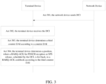
- FIG. 3 shows a flowchart of a method for indicating a DAI according to an exemplary embodiment of the present application, which is applied to the terminal device and the network device as shown in FIG. 1 .
- the method includes at least some of the following contents.
- the network device sends DCI.
- the network device can send one or more DCIs to the terminal device.
- DCIs can be sent to the terminal device.
- Embodiments of the present application are illustrated by taking the first DCI format and the second DCI format simultaneously existing in the multiple DCIs as an example.
- the terminal device receives the DCI.
- Each DCI includes a counter DAI field.
- the format of the DCI includes a first DCI format and/or a second DCI format.
- the counter DAI is the first counter DAI
- the bit of the first counter DAI is the first bit.
- the counter DAI is the second counter DAI
- the bit of the second counter DAI is the second bit.
- the terminal device determines a third counter DAI according to the counter DAI.
- the third counter DAI is used for the terminal device to determine a position of a HARQ-ACK fed back for PDSCH reception or SPS release, scheduled by the DCI format, in a HARQ-ACK codebook.
- the third counter DCI may be understood as a reference counter DAI, a base counter DAI, an intermediate counter DAI, a conversion counter DAI, and the like.
- the third counter DAI is used as an intermediate value or a reference value or a conversion value of the first counter DAI and the second counter DAI.
- the third counter DAI may be equal to the counter DAI in the DCI, or the third counter DAI may be equal to a numerical value obtained by performing an operation of modulo a positive integer M on the counter DAI in the DCI, or the third counter DAI may be equal to a sum of a modulus and y, wherein the modulus is a numerical value obtained by performing an operation of modulo the positive integer M on subtracted counter DAI that is obtained by subtracting y from the counter DAI, and y is a non-negative integer.
- the third counter DAI can be equal to a numerical value obtained by performing an operation of modulo a positive integer M on the counter DAI in the DCI
- the third counter DAI is equal to a sum of a modulus and y
- the modulus is a numerical value obtained by performing an operation of modulo the positive integer M on subtracted counter DAI that is obtained by subtracting y from the counter DAI
- y is a non-negative integer
- the third counter DAI may be equal to a numerical value obtained by performing an operation of modulo a positive integer M on the counter DAI in the DCI.
- the third counter DAI is equal to a sum of a modulus and y, the modulus is a numerical value obtained by performing an operation of modulo the positive integer M on subtracted counter DAI that is obtained by subtracting y from the counter DAI.
- the third counter DAI is equal to the first counter DAI, or the third counter DAI is equal to a numerical value obtained by performing an operation of modulo a positive integer M on the first counter DAI, or the third counter DAI is equal to a sum of a modulus and y.
- the modulus is a numerical value obtained by performing an operation of modulo the positive integer M on subtracted counter DAI that is obtained by subtracting y from the first counter DAI, and y is a non-negative integer.
- the third counter DAI is equal to the second counter DAI, or the third counter DAI is equal to a numerical value obtained by performing an operation of modulo a positive integer M on the second counter DAI, or the third counter DAI is equal to a sum of a modulus and y.
- the modulus is a numerical value obtained by performing an operation of modulo the positive integer M on subtracted counter DAI that is obtained by subtracting y from the second counter DAI, and y is a non-negative integer.
- the positive integer M is the minimum of the first parameter and the second parameter.
- the positive integer M is 2.
- the first parameter is determined by the first bit and the second parameter is determined by the second bit.
- the first parameter is equal to 2 to a power of the first bit and the second parameter is equal to 2 to a power of the second bit.
- the first bit is 2, then 2 to the power of the first bit is 4, and the second bit is 1, then 2 to the power of the second bit is 2.
- the positive integer M is the greatest common divisor of the first parameter and the second parameter.
- the greatest common divisor of the first parameter and the second parameter is 2, and the positive integer M is determined to be 2.
- the first parameter is determined by the first bit and the second parameter is determined by the second bit.
- the first parameter is equal to 2 to a power of the first bit and the second parameter is equal to 2 to a power of the second bit.
- the first bit is 2, then 2 to the power of the first bit is 4, and the second bit is 1, then 2 to the power of the second bit is 2.
- the first parameter corresponds to a first DCI format
- the second parameter corresponds to a second DCI format
- the first DCI format may be any one of DCI format 1_1, DCI format 0_1, DCI format 1_0 and DCI format 0_0
- the second DCI format may be any one of DCI format 0_2 and DCI format 1_2.
- any of the following items 1 to 8 may be included.
- the third counter DAI may be equal to a numerical value obtained by performing an operation of modulo a positive integer M on the counter DAI in the DCI, or the third counter DAI may be equal to a sum of a modulus and y, the modulus is a numerical value obtained by performing an operation of modulo the positive integer M on subtracted counter DAI that is obtained by subtracting y from the counter DAI, and y is a non-negative integer, any of the following items 1 to 4 may be included.
- the third counter DAI may be equal to a numerical value obtained by performing an operation of modulo a positive integer M on the counter DAI in the DCI, or the third counter DAI may be equal to a sum of a modulus and y, wherein the modulus is a numerical value obtained by performing an operation of modulo the positive integer M on subtracted counter DAI that is obtained by subtracting y from the counter DAI, and y is a non-negative integer.
- the third counter DAI is equal to a numerical value obtained by performing an operation of modulo a positive integer M on the counter DAI in the DCI, or the third counter DAI may be equal to a sum of a modulus and y, wherein the modulus is a numerical value obtained by performing an operation of modulo the positive integer M on subtracted counter DAI that is obtained by subtracting y from the counter DAI, and y is a non-negative integer.
- the third counter DAI is equal to a numerical value obtained by performing an operation of modulo a positive integer M on the counter DAI in the DCI, or the third counter DAI may be equal to a sum of a modulus and y, the modulus is a numerical value obtained by performing an operation of modulo the positive integer M on subtracted counter DAI that is obtained by subtracting y from the counter DAI, and y is a non-negative integer.
- the third counter DAI is directly determined by means of indication information.
- the terminal device determines a position of a HARQ-ACK fed back for PDSCH reception or SPS release, scheduled by DCI, in a HARQ-ACK codebook according to the third counter DAI.
- the terminal device After the terminal device determines the effective bit of the counter DAI field in the DCI, the terminal device determines the third counter DAI according to the bit of the counter DAI field, and then determines a position of a HARQ-ACK fed back for PDSCH reception or SPS release, scheduled by the DCI format, in a HARQ-ACK codebook according to the third counter DAI.
- the terminal device receives the DCI, determines the third counter DAI according to the counter DAI field in the DCI, and determines the position of a HARQ-ACK fed back for PDSCH reception or SPS release, scheduled by the DCI, in a HARQ-ACK codebook according to the third counter DAI.
- the terminal device first determines the third counter DAI according to the counter DAI field, even if the bits of different counter DAI fields are different, the counter DAI fields may be converted into a third counter DAI, and then a position of a HARQ-ACK fed back for PDSCH reception or SPS release scheduled by DCI, in a HARQ-ACK codebook is determined according to the third counter DAI, so as to prevent the situation in which the determined position of the HARQ-ACK is wrong due to the different bits of the counter DAIs, thereby ensuring the accuracy of the determined position of the HARQ-ACK.
- the act 304 shown in FIG. 3 has at least three different calculation manners, which are described as follows using FIG. 4 , FIG. 5 and FIG. 6 respectively.
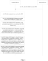
- FIG. 4 shows a flowchart of a method for indicating a DAI according to an exemplary embodiment of the present application.
- the act 304 may be replaced by an implementation of acts 4011-4013.
- the terminal device determines a first flip accumulation parameter j_1 corresponding to the first counter DAI and a second flip accumulation parameter j_2 corresponding to the second counter DAI according to the third counter DAI.
- different third counter DAIs may be determined according to the first bit or the second bit, and then the first flip accumulation parameter j_1 corresponding to the first counter DAI and the second flip accumulation parameter j_2 corresponding to the second counter DAI may be determined according to the third counter DAI.
- the terminal device determines a position of a HARQ-ACK fed back for PDSCH reception or SPS release scheduled by DCI, in a HARQ-ACK codebook according to the first counter DAI and the first flip accumulation parameter j_1.
- the first bit of the first counter DAI field is 1 bit
- the third counter DAI is set as the value DAI_1 of the first bit.
- the value of the first flip accumulation parameter j_1 corresponding to the first counter DAI is increased by 1.
- j_1 remains unchanged and the position of HARQ-ACK in the HARQ-ACK codebook is calculated as 2 ⁇ j_1+DAI_1.
- DAI_1 represents the value when the first bit of the first counter DAI field is 1 bit.
- the terminal device determines a position of a HARQ-ACK fed back for PDSCH reception or SPS release scheduled by DCI, in the HARQ-ACK codebook according to the second counter DAI and the second flip accumulation parameter j_2.
- the second bit of the second counter DAI field is 2 bits
- the third counter DAI is set as MOD (DAI_2, 2)
- DAI_2 is the value of the second bit of the second counter DAI field.
- the HARQ-ACK bit number in the HARQ-ACK codebook is calculated as 4*j_2+DAI_2. For example, if the value of j_2 is 1 and the value of DAI_2 is 0, the HARQ-ACK bit number is determined to be 4.
- Table 2 Actual number Y of transmissions 0 1 2 3 4 5 6
- Second counter DAI value (2bits) Ymod4 0 2 0 2
- First counter DAI value (1bit) Ymod2 1 1 1 1
- the second flip accumulation parameter j_2 corresponding to the second counter DAI 0 0 0 0 1 1 1 1
- the first flip accumulation parameter j_1 corresponding to the first counter DAI field 0 0 1 1 2 2 3
- Position of HARQ-ACK 4 ⁇ j_2+DAI_2 0 2 4 6
- Position of HARQ-ACK 2 ⁇ j_1+DAI_1 1 3 5
- a HARQ-ACK codebook window 7 PDSCH transmissions are included.
- the bit of the counter DAI field in the first DCI received by the terminal device is 2 bits, then the value DAI_2 of the counter DAI field is determined to be 0, the MOD (DAI_2, 2) is calculated as 0, the value of the third counter DAI is determined to be 0, and in addition, the third counter DAI last time does not exist, then the determined j_2 is also 0, and the determined position of HRAQ-ACK is 0.
- the value DAI_1 of the counter DAI field is determined to be 1.
- the third counter DAI is set to be the same as DAI_1, the value of the obtained third counter DAI is 1.
- the value of the third counter DAI this time is not less than a value of a third counter DAI last time, so it is determined that j_1 is 0 and j_2 is 0, and the obtained position of the HRAQ-ACK by calculating is 1.
- the value DAI_2 of the counter DAI field is determined to be 2.
- the MOD (DAI_2, 2) is calculated to be 0, the value of the third counter DAI is determined to be 0, and the value of the third counter DAI is less than a value of a third counter DAI last time, but the value of the third counter DAI is less than a value of a third counter DAI last time only once, it is determined that j_2 is 0 and j_1 is 1, and the obtained position of the HRAQ-ACK by calculating is 2.
- the value DAI_1 of the counter DAI field is determined to be 1.
- the third counter DAI is set to be the same as DAI_1, the value of the obtained third counter DAI is 1.
- the value of the third counter DAI this time is not less than a value of a third counter DAI last time, so it is determined that j_1 is 1 and j_2 is 0, and the obtained position of the HRAQ-ACK by calculating is 3.
- the value DAI_2 of the counter DAI field is determined to be 0.
- the MOD (DAI_2, 2) is calculated as 0, the value of the third counter DAI is determined to be 0, and the value of the third counter DAI this time is less than a value of a third counter DAI last time, and the value of the third counter DAI is less than a value of a third counter DAI last time for twice, it is determined that j_2 is 1 and j_1 is 2, and the obtained position of the HRAQ-ACK by calculating is 4.
- the value DAI_1 of the counter DAI field is determined to be 1.
- the third counter DAI is set to be the same as DAI_1, the value of the obtained third counter DAI is 1.
- the value of the third counter DAI this time is not less than a value of a third counter DAI last time, so it is determined that j_1 is 2 and j_2 is 0, and the obtained position of the HRAQ-ACK by calculating is 5.
- the value DAI_2 of the counter DAI field is determined to be 2.
- the MOD (DAI_2, 2) is calculated as 0, the value of the third counter DAI is determined to be 0, and the value of the third counter DAI this time is determined to be less than a value of a third counter DAI last time, and the value of the third counter DAI is less than a value of a third counter DAI last time once, it is determined that j_2 is 1, and j_1 is 3, and the obtained position of the HRAQ-ACK by calculating is 6.
- the HARQ-ACK positions determined in turn are 0, 1, 2, 3, 4, 5 and 6, respectively, which are the same as the position numbers of the PDSCH transmissions.
- DAI_1, DAI_2, j_1 and j_2 are examples.
- the values are not limited to DAI_1, DAI_2, j_1 and j_2, and may be expressed in other ways.
- FIG. 5 shows a flowchart of a method for indicating a DAI according to an exemplary embodiment of the present application.
- the act 4011 may be replaced by an implementation of acts 5011-5012.
- the terminal device determines a flip accumulation parameter j_e according to the third counter DAI.
- the terminal device determines a first flip accumulation parameter j_1 and a second flip accumulation parameter j_2 according to the third counter DAI and the flip accumulation parameter j_e.
- the flip accumulation parameter j_e is cumulatively increased when the third counter DAI is less than the third parameter.
- the third parameter is a positive integer.
- the third parameter may be 1, 2, 3 or other values.
- the flip accumulation parameter j_e is cumulatively increased, and j_e is 2.
- the flip accumulation parameter j_e is not cumulatively increased, and j_e is 1.
- the third parameter includes a historical third counter DAI.
- the third counter DAI determined at last time is taken as the third parameter
- the third counter DAI determined this time is compared with the third counter DAI determined at last time, and whether the third counter DAI determined this time is smaller than the third counter DAI determined at last time is determined, thereby whether the flip accumulation parameter j_e is cumulatively increased is determined.
- the third parameter may also include a maximum of multiple values of the third counter DAI.
- the third parameter is determined to be the maximum 4 among the third counter DAIs
- each determined third counter DAI is subsequently compared with the third parameter 4, whether the third counter DAI is smaller than the third parameter each time is determined, and the flip accumulation parameter j_e is cumulatively increased.
- the third counter DAI when the first bit of the first counter DAI field is 1 bit, the third counter DAI is set as the value DAI_1 of the first bit of the first counter DAI field.
- the value of the flip accumulation parameter j_e is increased by 1.
- the value of the third counter DAI is not less than a value of a third counter DAI last time, j_c remains unchanged, and the first flip accumulation parameter j_1 corresponding to the first counter DAI field is set to be the same as j_e, and the position of the HARQ-ACK in the HARQ-ACK codebook is calculated as 2 ⁇ j_1+DAI_1.
- DAI_1 represents the value when the first bit of the first counter DAI field is 1 bit.
- the value of the third counter DAI determined last time is 1, and the value of j_e determined last time is 0, the value of j_e determined this time is 1.
- the value of j_e remains unchanged, that is, the value of j_e this time is the same as that of j_e last time.
- the value of j_1 is set to be the same as that of j_e.
- the position of the HARQ-ACK in the HARQ-ACK codebook may be calculated as 2 ⁇ j_1+DAI_1 based on the determined j_1 and the first bit of the first counter DAI field.
- the position of the HARQ-ACK is determined to be 3.
- the second bit of the second counter DAI field is 2 bits
- the third counter DAI is set to be MOD (DAI_2, 2).
- the value of the flip accumulation parameter j_e is increased by 1.
- j_e remains unchanged.
- the position of the HARQ-ACK in a HARQ-ACK codebook is calculated as 4 ⁇ j_2+DAI_2. For example, if the value of j_2 is 1 and the value of DAI_2 is 0, the bit number of the HARQ-ACK is determined to be 4.
- Table 3 Actual number Y of transmissions 0 1 2 3 4 5 6
- Second counter DAI (2bits) Ymod4 0 2 0 2
- First counter DAI value (1bit) Ymod2 1 1 1 1
- Flip accumulation parameter j_e 0 0 1 1 2 2 3
- the second flip accumulation parameter j_2 corresponding to the second counter DAI 0 0 0 0 1 1 1 1
- the first flip accumulation parameter j_1 corresponding to the first counter DAI field 0 0 1 1 2 2 3
- Position of HARQ-ACK 4 ⁇ j_2+DAI_2 0 2 4 6
- Position of HARQ-ACK 2 ⁇ j_1+DAI_1 1 3 5
- the value DAI_1 of the counter DAI field is determined to be 1.
- the third counter DAI is set to be the same as DAI_1, the value of the obtained third counter DAI is 1.
- the value of the third counter DAI this time is not less than the value of the last third counter DAI, so it is determined that j_e is 0, j_1 is set to be the same as j_e, the value of j_1 is also 0, and the obtained position of the HRAQ-ACK by calculating is 1.
- the value DAI_2 of the counter DAI field is determined to be 2.
- the MOD (DAI_2, 2) is calculated to be 0, the value of the third counter DAI is determined to be 0, and the value of the third counter DAI this time is less than a value of a third counter DAI last time, the determined j_e is 1, and the current j_e changes from 0 to 1, it is determined that j_2 is 0 and j_1 is 1, and the determined position of the HRAQ-ACK is 2.
- the value DAI_1 of the counter DAI field is determined to be 1.
- the third counter DAI is set to be the same as DAI_1, the value of the obtained third counter DAI is 1.
- the value of the third counter DAI this time is not less than the value of the last third counter DAI, so it is determined that j_e is 0, j_1 is set to be the same as j_e, the value of j_1 is also 0, the value of j_2 is 0, and the obtained position of the HRAQ-ACK by calculating is 3.
- the value DAI_2 of the counter DAI field is determined to be 0.
- the MOD (DAI_2, 2) is calculated to be 0, the value of the third counter DAI is determined to be 0, and the value of the third counter DAI this time is less than a value of a third counter DAI last time, the determined j_e is 2, and the j_e this time changes from 1 to 2, it is determined that j_2 is 1 and j_1 is 2, and the determined position of the HRAQ-ACK is 4.
- the value DAI_1 of the counter DAI field is determined to be 1.
- the third counter DAI is set to be the same as DAI_1, the value of the obtained third counter DAI is 1.
- the value of the third counter DAI this time is not less than the value of the last third counter DAI, so it is determined that j_e is 2, j_1 is set to be the same as j_e, the value of j_1 is also 2, the value of j_2 is 1, and the obtained position of the HRAQ-ACK by calculating is 5.
- the value DAI_2 of the counter DAI field is determined to be 2.
- the MOD (DAI_2, 2) is calculated to be 0, the value of the third counter DAI is determined to be 0, and the value of the third counter DAI this time is less than a value of a third counter DAI last time, the determined j_e is 3, and the j_e this time changes from 2 to 3, it is determined that j_2 is 1 and j_1 is 3, and the determined HRAQ-ACK position is 6.
- bit numbers of the HARQ-ACKs sequentially determined are 0, 1, 2, 3, 4, 5 and 6, respectively, which are the same as the position numbers of PDSCH transmissions.
- j_e DAI_1, DAI_2, j_1 and j_2
- the values are not limited to j_e, DAI_1, DAI_2, j_1 and j_2, and may be expressed in other ways.
- FIG. 6 shows a flowchart of a method for indicating a DAI according to an exemplary embodiment of the present application.
- the act 304 may be replaced by an implementation of acts 6011-6012.
- a flip accumulation parameter j_e is determined according to the third counter DAI.
- the flip accumulation parameter j_e is cumulatively increased when the third counter DAI is less than the third parameter, which is a positive integer.
- the third parameter includes a historical third counter DAI, or the third parameter includes a maximum of multiple values of the third counter DAI.
- the procedure of act 6011 is similar to the procedure of 5011 and will not be described here.
- act 6012 according to the third counter DAI and the flip accumulation parameter j_e, the position of the HARQ-ACK fed back for PDSCH reception or SPS release, scheduled by the DCI, in the HARQ-ACK codebook is determined.
- the first bit of the first counter DAI field is 1 bit
- the third counter DAI is set as the value DAI_1 of the effective bit of the first counter DAI field.
- the value of j_e is increased by 1.
- the value of the third counter DAI is not less than the value of the last third counter DAI, the value of j_e remains unchanged, and the position of the HARQ-ACK in the HARQ-ACK codebook is calculated as X_e ⁇ j_e+DAI_e.
- X_e is the number of values of the third counter DAI.
- the X_e may be the greatest common divisor of 2 to a power of the first bit and 2 to a power of the second bit.
- the second bit of the second counter DAI field is 2 bits
- the third counter DAI is set as MOD (DAI_2, 2)
- DAI_2 is the value of the second bit of the second counter DAI field.
- X_e is the number of values of the third counter DAI.
- Table 4 Actual number Y of transmissions 0 1 2 3 4 5 6
- Second counter DAI value (2bits) Ymod4 0 2 0 2
- First counter DAI value (1bit) Ymod2 1 1 1 1
- Position of HARQ-ACK X_e ⁇ j_e+DAI_e 0 1 2 3 4 5 6
- a HARQ-ACK codebook window 7 PDSCH transmissions are included.
- the bit of the counter DAI field in the first DCI received by the terminal device is 2 bits, then the value DAI_2 of the counter DAI field is determined to be 0, the MOD (DAI_2, 2) is calculated to be 0, then the third counter DAI is determined to be 0, and the last third counter DAI does not exist, the determined j_2 is 0, then the determined position of the HRAQ-ACK is 0.
- the value DAI_1 of the counter DAI field is determined to be 1.
- the third counter DAI is set to be the same as DAI_1, the value of the obtained third counter DAI is 1.
- the value of the third counter DAI this time is not less than the value of the last third counter DAI, the j_e is determined to be 0, and the determined position of the HRAQ-ACK is 1.
- the bit of the counter DAI field in the third DCI received by the terminal device is 2 bits, then the value DAI_2 of the counter DAI field is determined to be 2.
- the MOD (DAI_2, 2) is calculated to be 0, the third counter DAI is determined to be 0, and the third counter DAI this time is 0, which is less than a value 1 of a third counter DAI last time.
- the value of j_e is increased by 1, so that the value of the obtained j_e is 1, and the determined position of the HRAQ-ACK is 2.
- the value DAI_1 of the counter DAI field is determined to be 1.
- the third counter DAI is set to be the same as DAI_1, the value of the obtained third counter DAI is 1.
- the value of the third counter DAI this time is not less than the value of the last third counter DAI, the j_e is determined to be 1, the determined position of the HRAQ-ACK is 3.
- the bit of the counter DAI field in the fifth DCI received by the terminal device is 2 bits, then the value DAI_2 of the counter DAI field is determined to be 0, the MOD (DAI_2, 2) is calculated to be 0, and the third counter DAI is determined to be 0.
- the third counter DAI this time is 0, which is less than a value 1 of a third counter DAI last time.
- the value of j_e is increased by 1, and the value of the obtained j_e is 2, and the determined position of the HRAQ-ACK is 4.
- the value DAI_1 of the counter DAI field is determined to be 1.
- the third counter DAI is set to be the same as DAI_1, the value of the obtained third counter DAI is 1.
- the value of the third counter DAI this time is not less than the value of the last third counter DAI, the j_e is determined to be 2, the determined position of the HRAQ-ACK is 5.
- the bit of the counter DAI field in the seventh DCI received by the terminal device is 2 bits
- the value DAI_2 of the counter DAI field is determined to be 2
- the MOD (DAI_2, 2) is calculated to be 0
- the third counter DAI is determined to be 0, and the third counter DAI this time is 0, which is less than a value 1 of a third counter DAI last time
- the value of j_e is increased by 1
- the value of the obtained j_e is 3, and the determined position of the HRAQ-ACK is 6.
- the positions of HARQ-ACKs determined in turn are 0, 1, 2, 3, 4, 5 and 6, respectively, which are the same as the position numbers of PDSCH transmissions.
- V C ⁇ DAI , c , m DL ⁇ 1 is used to denote the value of the counter DAI scheduling PDSCH reception or SPS PDSCH release on the serving cell c in PDCCH monitoring occasion m when the counter DAI is 1 bit in a DCI format.
- V C ⁇ DAI , c , m DL ⁇ 2 is used to denote the value of the counter DAI scheduling PDSCH reception or SPS PDSCH release on the serving cell c in PDCCH monitoring occasion m when the counter DAI is 2 bit in a DCI format.
- V T ⁇ DAI , m DL is used to denote the equivalent value of the total DAI in a DCI format.
- V T ⁇ DAI , m DL ⁇ 1 is used to denote the value of the total DAI of 1 bit in a DCI format.
- V T ⁇ DAI , m DL -2 is used to denote the value of the total DAI of 2 bits in a DCI format.
- the terminal assumes that the values of the total DAIs in all DCI formats are the same.
- the N C ⁇ DAI DL is used to denote the minimum bit number of the counter DAI
- T D 2 N C ⁇ DAI DL
- V C ⁇ DAI , c , m DL _ temp is used to denote an actual value of the counter DAI, i.e., the first counter DAI or the second counter DAI, in a DCI format scheduling PDSCH reception or SPS PDSCH release on the serving cell c in PDCCH monitoring occasion m .
- V T ⁇ DAI , m DL ⁇ temp is used to denote an actual value of the total DAI in a DCI format.
- N C ⁇ DAI DL ⁇ i is used to denote the bit number of the i-th counter DAI
- T D greatest common divisor 2 N C ⁇ DAI , 0 DL , ... , 2 N C ⁇ DAI , i DL , ... , 2 N C ⁇ DAI , I DL .
- the terminal sends HARQ-ACK information in a PUCCH in slot n, and for any PUCCH format, the terminal determines o ⁇ 0 ACK , o ⁇ 1 ACK , ... , o ⁇ o ACK ⁇ 1 ACK for a total number of O ACK HARQ-ACK information bits, based on the following pseudocode.
- N C ⁇ DAI , 1 DL is used to denote the bits of counter DAI in DCI format 1_1 and N C ⁇ DAI , 2 DL is used to denote the bits of counter DAI in DCI format 1_2.
- T D 2 N C ⁇ DAI , 1 DL .
- v C ⁇ DAI , c , m DL ⁇ temp is used to denote the value of the counter DAI in the DCI format scheduling PDSCH reception or SPS PDSCH release on the serving cell c in PDCCH monitoring occasion m.
- v T ⁇ DAI , c , m DL ⁇ temp is used to denote the value of the total DAI in a DCI format.
- N C ⁇ DAI DL is used to denote the minimum bit number of the counter DAI
- T D 2 N C ⁇ DAI DL .
- V C ⁇ DAI , c , m DL _ temp is used to denote an actual value of the counter DAI, i.e., the first counter DAI or the second counter DAI, in a DCI format scheduling PDSCH reception or SPS PDSCH release on the serving cell c in PDCCH monitoring occasion m.
- V T ⁇ DAI , m DL ⁇ temp is used to denote an actual value of the total DAI in a DCI format.
- N C ⁇ DAI DL ⁇ i is used to denote the bit number of the i-th counter DAI
- T D T D greatest common divisor 2 N C ⁇ DAI , 0 DL , ... , 2 N C ⁇ DAI , i DL , ... , 2 N C ⁇ DAI , I DL .
- the terminal sends HARQ-ACK information in a PUCCH in slot n, and for any PUCCH format, the terminal determines o ⁇ 0 ACK , o ⁇ 1 ACK , ... , o ⁇ O ACK ⁇ 1 ACK , for a total number of O ACK HARQ-ACK information bits, based on the following pseudocode.
- V C ⁇ DAI , c , m DL mod v C ⁇ DAI , c , m DL ⁇ temp ⁇ y , T D + y ;
- V T ⁇ DAI , m DL mod v T ⁇ DAI , c , m DL ⁇ temp ⁇ y , T D + y .
- V C ⁇ DAI , c , m DL mod v C ⁇ DAI , c , m DL ⁇ temp ⁇ 1 , T D + 1 ;
- V T ⁇ DAI , m DL mod v T ⁇ DAI , c , m DL ⁇ temp ⁇ 1 , T D + 1 .
- the first DCI format further includes a first total DAI, and the first DCI format includes a third bit of the first total DAI; the second DCI format further includes a second total DAI, the second DCI format includes a fourth bit of the second total DAI, and the third bit and the fourth bit are independently configured.
- the third total DAI may also be determined according to the total DAI in the DCI, and the first bit of the first counter DAI field is replaced with the third bit of the first total DAI, and the second bit of the second counter DAI field is replaced with the fourth bit of the second total DAI. Subsequently, the third total DAI may be determined according to the act of determining the third counter DAI.
- the third total DAI may be equal to the total DAI in the DCI, or the third total DAI may be equal to a numerical value obtained by performing an operation of modulo a positive integer M on on the total DAI in the DCI.
- the positive integer M is the minimum of the third and fourth parameters.
- the positive integer M is the greatest common divisor of the third parameter and the fourth parameter.
- the third parameter is determined by the third bit and the fourth parameter is determined by the fourth bit.
- the third parameter is equal to 2 to a power of the third bit and the fourth parameter is equal to 2 to a power of the fourth bit.
- FIG. 7 is a flowchart of a method for sending a DAI according to an exemplary embodiment of the present application, which is applied to the terminal device and the network device as shown in FIG. 1 , and the method includes at least some of the following acts 701-703.
- a network device sends DCI.
- a terminal device receives the DCI.
- a bit of a counter DAI field in the DCI is a first bit.
- the network device sends DCI to the terminal device, and the DCI is used for scheduling PDSCH reception or SPS release.
- the terminal device receives the DCI, the first bit of the counter DAI field in the DCI may be determined, and a value of the counter DAI field may be determined.
- the terminal device sends a HARQ-ACK of a PDSCH reception or SPS release, scheduled by the DCI.
- the terminal device After receiving the DCI, the terminal device also needs to send the HARQ-ACK of the PDSCH reception or the SPS release, scheduled by the DCI, to the network device, so that the network device determines that the terminal device has successfully received the DCI.
- the first bit is not expected to be equal to 0.
- the first bit of the counter DAI field of the DCI may be 0 bit, 1 bit, 2 bits or bits of other values, and when the type 2 HARQ-ACK codebook is configured, the terminal device does not expect the first bit to be equal to 0, to prevent a situation where HARQ-ACK multiplexing cannot be performed.
- not expecting the first bit to be equal to 0 also means that the first bit is greater than 0, e.g., the first bit may be 1 bit, 2 bits, or bits of another numeric value.
- a resource position of the HARQ-ACK is determined according to the DCI, and the HARQ-ACK corresponding to the PDSCH reception or SPS release is sent on the resource position.
- the terminal device determines that HARQ-ACK multiplexing cannot be performed, and the terminal device may determine the resource position corresponding to the DCI in this case.
- the resource position is used to represent a time domain position and a frequency domain position in the transmission channel.
- the terminal device determines a PUCCH resource position based on the PDCCH resource indicator and the PDSCH-to-HARQ_feedback timing indicator in the DCI.
- the first bit of the counter DAI field in the DCI is 0 bit, which indicates that there is no counter DAI field in the DCI.
- the terminal device after receiving the DCI, the terminal device obtains the resource position indicated by the DCI and transmits the HARQ-ACK on the resource position, which can ensure that the terminal device accurately transmits the HARQ-ACK and ensure the accuracy of HARQ-ACK transmission.
- FIG. 8 shows a block diagram of a device for configuring a DAI according to an exemplary embodiment of the present application, which may be realized as a terminal device, or applied in the terminal device as shown in FIG. 1 .
- the device includes a determining module 801 and a receiving module 802.
- the determining module 801 is configured to determine a first bit of a first counter DAI in a first DCI format.
- the receiving module 802 is configured to receive configuration information, wherein the configuration information is used for configuring a second bit of a second counter DAI in a second DCI format.
- a HARQ-ACK for PDSCH reception or semi-persistent scheduling (SPS) release, scheduled by the first DCI format, and a HARQ-ACK for PDSCH reception or SPS release, scheduled by the second DCI format, are fed back in the same HARQ-ACK codebook.
- the first bit is the same as the second bit.
- an effective bit of the first bit is the same as that of the second bit.
- the effective bit is a minimum of the first bit and the second bit.
- bits other than the effective bit in the first bit of the first counter DAI are used for indicating other information other than the first counter DAI, or bits other than the effective bit in the second bit of the second counter DAI are used for indicating other information other than the second counter DAI.
- the other information at least includes one of the following:
- the HARQ-ACK codebook is a type 2 HARQ-ACK codebook.
- the configuration information is configured by high layer signaling.
- FIG. 9 shows a block diagram of a device for indicating a DAI according to an exemplary embodiment of the present application, which may be realized as a network device, or applied in the network device as shown in FIG. 1 .
- the device includes a determining module 901 and a sending module 902.
- the determining module 901 is configured to determine a first bit of a first counter DAI in a first DCI format.
- the sending module 902 is configured to send configuration information, wherein the configuration information is used for configuring a second bit of a second counter DAI in a second DCI format.
- a HARQ-ACK for PDSCH reception or SPS release, scheduled by the first DCI format, and a HARQ-ACK for PDSCH reception or SPS release, scheduled by the second DCI format are fed back in the same HARQ-ACK codebook.
- the first bit is the same as the second bit.
- an effective bit of the first bit is the same as that of the second bit.
- the effective bit is a minimum of the first bit and the second bit.
- bits other than the effective bit in the first bit of the first counter DAI are used for indicating other information other than the first counter DAI, or bits other than the effective bit in the second bit of the second counter DAI are used for indicating other information other than the second counter DAI.
- the other information at least includes one of the following:
- the HARQ-ACK codebook is a type 2 HARQ-ACK codebook.
- the configuration information is configured by high layer signaling.
- FIG. 10 shows a block diagram of a device for indicating a DAI according to an exemplary embodiment of the present application, which may be realized as a terminal device, or applied in the terminal device as shown in FIG. 1 .
- the device includes a receiving module 1001, a first determining module 1002 and a second determining module 1003.
- the receiving module 1001 is configured to receive DCI including a counter DAI field.
- the first determining module 1002 is configured to determine a third counter DAI according to the counter DAI.
- the second determining module 1003 is configured to determine a position of a HARQ-ACK fed back for PDSCH reception or SPS release, scheduled by the DCI, in a HARQ-ACK codebook according to the third counter DAI.
- a format of the DCI at least includes a first DCI format and/or a second DCI format; when the format of the DCI is the first DCI format, the counter DAI is a first counter DAI, and a bit of the first counter DAI is a first bit; when the format of the DCI is the second DCI format, the counter DAI is a second counter DAI, and a bit of the second counter DAI is a second bit.
- the third counter DAI is equal to the counter DAI; or, the third counter DAI is equal to a numerical value obtained by performing an operation of modulo a positive integer M on the counter DAI, or, the third counter DAI is equal to a sum of a modulus and y, wherein the modulus is a numerical value obtained by performing an operation of modulo the positive integer M on subtracted counter DAI that is obtained by subtracting y from the counter DAI, and y is a non-negative integer.
- the third counter DAI is equal to the counter DAI; or, when PDSCH reception or SPS release corresponding to a HARQ-ACK fed back in a same HARQ-ACK codebook is scheduled by the first DCI format and the second DCI format, and the first bit and the second bit are the same, the third counter DAI is equal to the counter DAI; or, when PDSCH reception or SPS release corresponding to a HARQ-ACK fed back in a same HARQ-ACK codebook is scheduled by the first DCI format and the second DCI format, and the bit of the counter DAI is the minimum of the first bit and the second bit, the third counter DAI is equal to the counter DAI; or, when PDSCH reception or SPS release corresponding to a HARQ-ACK fed back in a same HARQ-ACK codebook is
- the third counter DAI is equal to a numerical value obtained by performing an operation of modulo a positive integer M on the counter DAI, or the third counter DAI is equal to a sum of a modulus and y, wherein the modulus is a numerical value obtained by performing an operation of modulo the positive integer M on subtracted counter DAI that is obtained by subtracting y from the counter DAI, and y is a non-negative integer.
- the third counter DAI is equal to a numerical value obtained by performing an operation of modulo a positive integer M on the counter DAI, or, the third counter DAI is equal to a sum of a modulus and y, wherein the modulus is a numerical value obtained by performing an operation of modulo the positive integer M on subtracted counter DAI that is obtained by subtracting y from the counter DAI, and y is a non-negative integer.
- the third counter DAI is equal to a numerical value obtained by performing an operation of modulo a positive integer M on the counter DAI;, or, the third counter DAI is equal to a sum of a modulus and y, wherein the modulus is a numerical value obtained by performing an operation of modulo the positive integer M on subtracted counter DAI that is obtained by subtracting y from the counter DAI, and y is a non-negative integer.
- the third counter DAI is equal to a numerical value obtained by performing an operation of modulo a positive integer M on the counter DAI, or, the third counter DAI is equal to a sum of a modulus and y, wherein the modulus is a numerical value obtained by performing an operation of modulo the positive integer M on subtracted counter DAI that is obtained by subtracting y from the counter DAI, and y is a non-negative integer.
- the positive integer M is the minimum of a first parameter and a second parameter; or, the positive integer M is the greatest common divisor of the first parameter and the second parameter; wherein, the first parameter is determined by the first bit and the second parameter is determined by the second bit.
- the first parameter is equal to 2 to a power of the first bit; and/or, the second parameter is equal to 2 to a power of the second bit.
- the second determining module 1003 includes: a first determination unit 10031 and a second determination unit 10032.
- the first determination unit 10031 is configured to determine a flip accumulation parameter j_e according to the third counter DAI.
- the second determination unit 10032 is configured to determine, according to the third counter DAI and the flip accumulation parameter j_e, the position of the HARQ-ACK fed back for the PDSCH reception or SPS release, scheduled by the DCI, in the HARQ-ACK codebook.
- the second determining module 1003 includes a third determination unit 10034 configured to determine, according to the third counter DAI, a first flip accumulation parameter j_1 corresponding to the first counter DAI and a second flip accumulation parameter j_2 corresponding to the second counter DAI; a fourth determination unit 10034 configured to, when the DCI format is the first DCI format, determine the position of the HARQ-ACK fed back for PDSCH reception or SPS release, scheduled by the DCI, in the HARQ-ACK codebook according to the first counter DAI and the first flip accumulation parameter j_1; or, a fourth determination unit 10034 configured to, when the DCI format is the second DCI format, determine the position of the HARQ-ACK fed back for PDSCH reception or SPS release, scheduled by DCI, in the HARQ-ACK codebook according to the second counter DAI and the second flip accumulation parameter j_2.
- the third determination unit 10033 is configured to determine a flip accumulation parameter j_e according to the third counter DAI; and determine the first flip accumulation parameter j_1 and the second flip accumulation parameter j_2 according to the third counter DAI and the flip accumulation parameter j_e.
- the first determining module 1002 is configured to, when the third counter DAI is smaller than a third parameter, cumulatively increase the flip accumulation parameter j_e, wherein the third parameter is a positive integer.
- the third parameter includes a historical third counter DAI, or the third parameter includes a maximum of multiple values of the third counter DAI.
- the first DCI format further includes a first total DAI, and the first DCI format includes a third bit of the first total DAI;
- the second DCI format further includes a second total DAI, the second DCI format includes a fourth bit of the second total DAI, and the third bit and the fourth bit are independently configured;
- the device further includes: a third determining module 1004 configured to determine, according to the total DAI in the DCI, a third total DAI.
- FIG. 12 shows a block diagram of a device for sending a DAI according to an exemplary embodiment of the present application, which may be realized as a terminal device, or applied in the terminal device as shown in FIG. 1 .
- the device includes a receiving module 1201 and a sending module 1202.
- the receiving module 1201 is configured to receive Downlink Control Information (DCI), wherein a bit of a counter DAI field in the DCI is a first bit.
- DCI Downlink Control Information
- the sending module 1202 is configured to send a HARQ-ACK for Physical Downlink Shared Channel (PDSCH) reception or semi-persistent scheduling (SPS) release, scheduled by the DCI.
- PDSCH Physical Downlink Shared Channel
- SPS semi-persistent scheduling
- the first bit is not expected to be equal to 0.
- the device further includes: a determining module 1203 configured to determine, according to the DCI, a resource position of the HARQ-ACK when a type 2HARQ-ACK codebook is configured and the first bit is equal to 0; wherein the sending module 1202 is configured to only send the HARQ-ACK corresponding to the PDSCH reception or SPS release on the resource position.
- a determining module 1203 configured to determine, according to the DCI, a resource position of the HARQ-ACK when a type 2HARQ-ACK codebook is configured and the first bit is equal to 0; wherein the sending module 1202 is configured to only send the HARQ-ACK corresponding to the PDSCH reception or SPS release on the resource position.
- FIG. 14 shows a schematic diagram of a structure of a communication device (a terminal device or network device) according to an exemplary embodiment of the present application.
- the communication device includes a processor 1401, a receiver 1402, a transmitter 1403, a memory 1404 and a bus 1405.
- the processor 1401 includes one or more processing cores.
- the processor 101 performs various functional applications and information processing by running software programs and modules.
- the receiver 1402 and the transmitter 1403 may be implemented as a communication component, which may be a communication chip.
- the memory 1404 is connected to the processor 1401 via the bus 1405.
- the memory 1404 may be configured to store at least one instruction, and the processor 1401 is configured to execute the at least one instruction to implement various acts in the above method embodiments.
- the memory 1404 may be implemented by any type of transitory or non-transitory storage device or a combination thereof.
- the transitory or non-transitory storage device includes, but is not limited to, a magnetic disk or an optical disk, an Electrically Erasable Programmable Read Only Memory (EEPROM), an Erasable Programmable Read Only Memory (EPROM), a Static Random Access Memory (SRAM), a Read Only Memory (ROM), a magnetic memory, a flash memory, and a Programmable Read Only Memory (PROM).
- a computer-readable storage medium in which executable instructions are stored, the executable instructions are loaded and executed by the processor to implement a method for configuring a DAI or a method for indicating a DAI or a method for sending a DAI, executed by the communication device and provided by the respective method embodiments above.
Landscapes
- Engineering & Computer Science (AREA)
- Signal Processing (AREA)
- Computer Networks & Wireless Communication (AREA)
- Mobile Radio Communication Systems (AREA)
- Communication Control (AREA)
Abstract
Description
- The present application relates to the field of mobile communication, in particular to a method for configuring a DAI (Downlink Assignment Index), a method for indicating a DAI, a method for sending a DAI, a device and a medium.
- At present, in a wireless communication network, a terminal device communicates with a network device, and the terminal device may send HARQ-ACK (Hybrid Automatic Repeat reQuest Acknowledgement) information to the network device, so that the network device can determine whether the terminal device correctly receives data.
- In the related technology, a network device sends a DCI (Downlink Control Information) message to a terminal device, and a DAI field carried in the DCI may be used to count sent DCI messages, and the terminal device generates a dynamic HARQ-ACK codebook according to the DAI field, to feed back to the network device whether the terminal device receives the message correctly.
- In the related technology, the counter DAI field is indicated by 2 bits, and then a position of a HARQ-ACK in a HARQ-ACK codebook is determined by means of counter DAI+j*4. However, in other designs, a scheme of DAI field indicated by 1 bit is proposed. When there may be DAIs with different bit numbers in multiple DCIs corresponding to the same HARQ-ACK feedback window, a conflict will occurs in a determination process of the above positions, thereby the determination process of the above positions cannot be used normally.
- Embodiments of the present application provide a method for configuring a DAI, a method for indicating a DAI, a method for sending a DAI, a device and a medium. The technical solutions are as follows.
- According to one aspect of the present application, a method for configuring a DAI, applied to a terminal device, is provided. The method includes: determining a first bit of a first counter DAI in a first DCI format; receiving configuration information, wherein the configuration information is used for configuring a second bit of a second counter DAI in a second DCI format; wherein a Hybrid Automatic Repeat Request Acknowledgement (HARQ-ACK) for Physical Downlink Shared Channel (PDSCH) reception or semi-persistent scheduling (SPS) release, scheduled by the first DCI format, and a HARQ-ACK for PDSCH reception or SPS release, scheduled by the second DCI format, are fed back in a same HARQ-ACK codebook.
- According to one aspect of the present application, a method for configuring a DAI, applied to a network device, is provided. The method includes: determining a first bit of a first counter DAI in a first DCI format; sending configuration information, wherein the configuration information is used for configuring a second bit of a second counter DAI in a second DCI format;
wherein a Hybrid Automatic Repeat Request Acknowledgement (HARQ-ACK) for Physical Downlink Shared Channel (PDSCH) reception or semi-persistent scheduling (SPS) release, scheduled by the first DCI format, and a HARQ-ACK for PDSCH reception or SPS release, scheduled by the second DCI format, are fed back in a same HARQ-ACK codebook. - According to one aspect of the present application, a method for indicating a DAI, applied to a terminal device, is provided. The method includes: receiving DCI, wherein the DCI includes a counter DAI field;
- determining a third counter DAI according to the counter DAI field;
- determining, according to the third counter DAI, a position of a HARQ-ACK fed back for PDSCH reception or SPS release, scheduled by the DCI, in a HARQ-ACK codebook.
- According to one aspect of the present application, a method for sending a DAI, applied to a terminal device, is provided. The method includes: receiving Downlink Control Information (DCI), wherein a bit of a counter DAI field in the DCI is a first bit; sending a HARQ-ACK for PDSCH reception or SPS release, scheduled by the DCI.
- According to one aspect of the present application, a device for configuring a DAI is provided. The device includes: a determining module configured to determine a first bit of a first counter DAI in a first DCI format; a receiving module configured to receive configuration information, wherein the configuration information is used for configuring a second bit of a second counter DAI in a second DCI format; wherein, a Hybrid Automatic Repeat Request Acknowledgement (HARQ-ACK) for Physical Downlink Shared Channel (PDSCH) reception or semi-persistent scheduling (SPS) release, scheduled by the first DCI format, and a HARQ-ACK for PDSCH reception or SPS release, scheduled by the second DCI format, are fed back in a same HARQ-ACK codebook.
- According to one aspect of the present application, a device for configuring a DAI is provided. The device includes: a determining module configured to determine a first bit of a first counter DAI in a first DCI format; a sending module configured to send configuration information, wherein the configuration information is used for configuring a second bit of a second counter DAI in a second DCI format; wherein, a Hybrid Automatic Repeat Request Acknowledgement (HARQ-ACK) for Physical Downlink Shared Channel (PDSCH) reception or semi-persistent scheduling (SPS) release, scheduled by the first DCI format, and a HARQ-ACK for PDSCH reception or SPS release, scheduled by the second DCI format, are fed back in a same HARQ-ACK codebook.
- According to one aspect of the present application, a device for indicating a DAI is provided. The device includes: a receiving module configured to receive DCI, wherein the DCI includes a counter DAI; a first determining module configured to determine a third counter DAI according to the counter DAI field in the DCI; a second determining module configured to determine, according to the third counter DAI, a position of a HARQ-ACK fed back for the PDSCH reception or SPS release, scheduled by the DCI, in a HARQ-ACK codebook.
- According to one aspect of the present application, a device for sending a DAI is provided. The device includes: a receiving module configured to receive DCI, wherein a bit of a counter DAI field in the DCI is a first bit; a sending module configured to send a HARQ-ACK for PDSCH reception or SPS release, scheduled by the DCI.
- According to one aspect of the present application, a terminal is provided, the terminal includes: a processor; a transceiver connected to the processor; a memory for storing executable instructions of the processor; wherein the processor is configured to load and execute the executable instructions to implement the method for configuring the DAI, or the method for indicating the DAI, or the method for sending the DAI, as described in the above aspects.
- According to one aspect of the present application, a network device is provided, the network device includes: a processor; a transceiver connected to the processor; and a memory for storing executable instructions of the processor; wherein the processor is configured to load and execute the executable instructions to implement the method for configuring the DAI as described in the above aspects.
- According to one aspect of the present application, a computer-readable storage medium is provided. Executable instructions are stored in the computer-readable storage medium, and the executable instructions are loaded and executed by a processor to implement the method for configuring the DAI, or the method for indicating the DAI, or the method for sending the DAI, as described in the above aspects.
- The technical solutions according to the embodiments of the present application at least include the following beneficial effects.
- The present application provides a method for configuring a DAI. A terminal device determines a first bit of a first counter DAI in a first DCI format. After receiving the configuration information, according to the configuration information, the second bit of the second counter DAI in the second DCI format is determined, and the first bit and the second bit are same, it may be determined that the bits of the counter DAI fields corresponding to the PDSCH reception or the SPS release corresponding to the HARQ-ACKs in a HARQ-ACK codebook are same, and it can be ensured that the accuracy of the determined HARQ-ACK position when the terminal device determines the HARQ-ACK position according to the counter DAI field later.
- The invention provides a method for indicating a DAI. A terminal device receives DCI, determines a third counter DAI according to a counter DAI field in the DCI, and determines the position of a HARQ-ACK fed back for PDSCH reception or SPS release, scheduled by the DCI, in a HARQ-ACK codebook according to the third counter DAI. Since the terminal device first determines the third counter DAI according to the counter DAI field, even if the bits of different counter DAI fields are different, the counter DAI fields can be converted into a third counter DAI. Then the position of the HARQ-ACK fed back for PDSCH reception or SPS release, scheduled by DCI, in a HARQ-ACK codebook is determined according to the third counter DAI, so as to prevent the situation in which the position of the determined HARQ-ACK is wrong due to the different bits of the counter DAI, ensuring the accuracy of the determined position of the HARQ-ACK.
- The invention provides a method for sending a DAI. The first bit of the counter DAI field in DCI is 0 bit, which shows that there is no counter DAI field in the DCI. In this case, after receiving the DCI, the terminal device obtains the resource position indicated by the DCI and transmits HARQ-ACK on the resource position, which can ensure the terminal device accurately transmits the HARQ-ACK and ensure the accuracy of HARQ-ACK transmission.
- In order to describe technical solutions in the embodiments of the present application more clearly, drawings that need to be used in the description of the embodiments will be briefly introduced below. It is apparent that the drawings described below are only some embodiments of the present application, and for those of ordinary skills in the art, other drawings may be obtained according to these drawings without paying inventive efforts.
-
FIG. 1 shows a block diagram of a communication system according to an exemplary embodiment of the present application. -
FIG. 2 shows a flowchart of a method for configuring a DAI according to an exemplary embodiment of the present application. -
FIG. 3 shows a flowchart of a method for indicating a DAI according to an exemplary embodiment of the present application. -
FIG. 4 shows a flowchart of a method for indicating a DAI according to an exemplary embodiment of the present application. -
FIG. 5 shows a flowchart of a method for indicating a DAI according to an exemplary embodiment of the present application. -
FIG. 6 shows a flowchart of a method for indicating a DAI according to an exemplary embodiment of the present application. -
FIG. 7 shows a flowchart of a method for sending a DAI according to an exemplary embodiment of the present application. -
FIG. 8 shows a block diagram of a device for configuring a DAI according to an exemplary embodiment of the present application. -
FIG. 9 shows a block diagram of a device for indicating a DAI according to an exemplary embodiment of the present application. -
FIG. 10 shows a block diagram of a device for indicating a DAI according to an exemplary embodiment of the present application. -
FIG. 11 shows a block diagram of a device for indicating a DAI according to an exemplary embodiment of the present application. -
FIG. 12 shows a block diagram of a device for sending a DAI according to an exemplary embodiment of the present application. -
FIG. 13 shows a block diagram of a device for sending a DAI according to an exemplary embodiment of the present application. -
FIG. 14 shows a schematic diagram of a structure of a communication device according to an exemplary embodiment of the present application. - In order to make objects, technical solutions, and advantages of the present application clearer, implementations of the present application will be described in further detail below with reference to the drawings.
-
FIG. 1 shows a block diagram of a communication system according to an exemplary embodiment of the present application, which may include anaccess network 12 and aterminal device 14. - The
access network 12 includesmultiple network devices 120. Thenetwork device 120 may be a base station, which is a device deployed in an access network to provide a wireless communication function for a terminal. The base station may include macro base stations, micro base stations, relay stations, access points, etc. of various forms. In systems using different radio access technologies, names of devices with base station functions may be different. For example, in the LTE system, it is called eNodeB or eNB; in the 5G NR-U system, it is called gNodeB or gNB. With the evolution of communication technology, the description of "base station" may change. For convenience, in the embodiments of the present application, the above-mentioned devices for providing wireless communication functions for theterminal device 14 are collectively referred to as access network devices. - The
above terminal device 14 may include various handheld devices, vehicle-mounted devices, wearable devices, computing devices, that have wireless communication functions, or other processing devices connected to a wireless modem, and various types of user equipments, Mobile Stations (MSs), terminal devices, and the like. For convenience of description, the above-mentioned devices are collectively referred to as terminals. Theaccess network device 120 and theterminal device 14 communicate with each other via some air interface technology such as a Uu interface. - The technical solutions of the embodiments of the present application may be applied to various communication systems, such as a Global System of Mobile communication (GSM) system, a Code Division Multiple Access (CDMA) system, a Wideband Code Division Multiple Access (WCDMA) system, a General Packet Radio Service (GPRS) system, a Long Term Evolution (LTE) system, an LTE Frequency Division Duplex (FDD) system, an LTE Time Division Duplex (TDD) system, an Advanced Long Term Evolution (LTE-A) system, a New Radio (NR) system, an evolution system of an NR system, an LTE-based access to unlicensed spectrum (LTE-U) system, an NR-based access to unlicensed spectrum (NR-U) system, a Universal Mobile Telecommunications System (UMTS), a Worldwide Interoperability for Microwave Access (WiMAX) communication system, Wireless Local Area Networks (WLANs), Wireless Fidelity (WiFi), a next generation communication system, or other communication systems.
- Generally, traditional communication systems support a limited quantity of connections, and are easy to implement. However, with the development of communication technology, mobile communication systems will not only support traditional communications, but also support, for example, Device to Device (D2D) communication, Machine to Machine (M2M) communication, Machine Type Communication (MTC), Vehicle to Vehicle (V2V) communication, and Vehicle to everything (V2X) system, etc. The embodiments of the present application are also applicable to these communication systems.
- In related art, for dynamic HARQ-ACK codebook, a position of a HARQ-ACK for PDSCH reception or SPS release in a HARQ-ACK codebook corresponds to a transmission number of the PDSCH reception or SPS release in the HARQ-ACK codebook.
- Optionally, the position of PDSCH reception or SPS release in the HARQ-ACK codebook is indicated by a value of a counter DAI.
- It should be noted that since bits in the counter DAI field are limited, only the counter DAI is used, and the counter DAI cannot correspond to the transmission number one to one. Therefore, the transmission number corresponding to the counter DAI is determined by means of modulus operation.
- Herein, the value of the counter DAI field = MOD (transmission number Y of PDSCH reception or SPS release in a HARQ-ACK codebook, 4).
- For example, when Y=1, 2, 3, 4, 5, 6, according to the above formula, it can be determined that the counter DAI=1, 2, 3, 0, 1, 2.
- Furthermore, in order to determine Y corresponding to the counter DAI, an accumulation of the number of flips j of the counter DAI is added in the protocol, and Y=counter DAI+j*4.
- When the value of DAI is less than a value of a DAI last time, the value of j is increased by 1.
- In the same HARQ-ACK codebook window, if the bits of the counter DAI field are 2 bits, the Y corresponding to each counter DAI may be determined in sequence by adopting the above manner, and the determined Y value is the correct transmission number.
- However, if the bits of the counter DAI fields corresponding to the PDSCH reception or SPS release corresponding to the HARQ-ACK in the same HARQ-ACK codebook are different, an error will occur in determining the position of the HARQ-ACK in the above manner.
- For example, as shown in
FIG. 1 , there are seven PDSCH transmissions, i.e., 0, 1, 2, 3, 4, 5, and 6, in one HARQ-ACK codebook window. These seven PDSCH transmissions are polled 2-bit DAI and 1-bit DAI indications in turn, and the DAI values are values in row 2 and row 3 of Table 1, respectively. Alternatively, the numbers of flips j determined from the DAI values are shown in row 4 of Table 1. Then positions of HARQ-ACK bits calculated by the above manner are 0, 1, 2, 5, 8, 9 and 10, and the positions of HARQ-ACK bits corresponding to PDSCH transmissions 3, 4, 5 and 6 are wrongly calculated as 5, 8, 9 and 10, which leads to the inconsistency between the actual PDSCH transmission number and the calculated PDSCH transmission number, resulting in that the network device is unable to correctly interpret the corresponding relationship between HARQ-ACK information field and the PDSCH.Table 1 Actual number of transmissions Y 0 1 2 3 4 5 6 Counter DAI value (2bits) = Ymod4 0 2 0 2 Counter DAI value (1bit) = Ymod2 1 1 1 Counter DAI numbers of flips (2bits) j 0 0 0 1 2 2 2 Position of HARQ-ACK = 4*j+DAI value 0 1 2 5 8 9 10 - The present application provides at least three solutions to the above technical problems, which are respectively described below (in no particular order).
- In the embodiment shown in
FIG. 2 , the first bit of the first counter DAI field of the first DCI format configured by the network device for the terminal device is the same as the second bit of the second counter DAI field of the second DCI format, and later the terminal device determines accuracy of positions of HARQ-ACKs fed back for PDSCH reception or SPS release, scheduled by the first DCI format, and PDSCH reception or SPS release, scheduled by the first DCI format, in a HARQ-ACK codebook according to the first counter DAI and the second counter DAI. In the embodiments shown inFIGS. 3-6 , the terminal device determines the corresponding third counter DAI according to the counter DAI field in the DCI, where the determined third counter DAI is a reference counter DAI, then the terminal device determines a position of a HARQ-ACK fed back for PDSCH reception or SPS release, scheduled by the DCI, in a HARQ-ACK codebook according to the third counter DAI. In the embodiment shown inFIG. 7 , the terminal device determines the resource position directly according to the received DCI, and sends a HARQ-ACK for PDSCH reception or SPS release, scheduled by DCI, on the resource position. - For the first possible solution
-
FIG. 2 shows a flowchart of a method for configuring a DAI according to an exemplary embodiment of the present application, which is applied to the terminal device and the network device as shown inFIG. 1 . The method includes at least some of the following contents. - In
act 201, a network device determines a first bit of a first counter DAI in a first DCI format. - In
act 202, a terminal device determines the first bit of the first counter DAI in the first DCI format. - Alternatively, the first bit is agreed in a protocol. The first DCI format may be any one of DCI format 1_1, DCI format 0_1, DCI format 1_0 and DCI format 0_0.
- Alternatively, the first bit is 1 bit or 2 bits.
- In act 203, the network device sends configuration information.
- In act 204, the terminal device receives the configuration information.
- Herein, the configuration information is used for configuring a second bit of a second counter DAI in a second DCI format.
- The terminal device may first determine the first bit of the first counter DAI in the first DCI format, then receive configuration information, and determine a second bit of a second counter DAI in a second DCI format according to the configuration information.
- Alternatively, the terminal device may first determine the first bit of the first counter DAI in the first DCI format and then determine the second bit of the second counter DAI in the second DCI format according to the configuration information. Alternatively, the terminal device may first determine the second bit of the second counter DAI in the second DCI format, and then determine the second bit of the first counter DAI in the first DCI format according to the configuration information. Alternatively, the terminal device may simultaneously determine the first bit of the first counter DAI in the first DCI format and the second bit of the second counter DAI in the second DCI format according to the configuration information.
- Alternatively, the second DCI format may be any one of DCI format0_2, DCI format1_2. Alternatively, the second bit is 1 bit or 2 bits.
- Herein, a HARQ-ACK for the PDSCH reception or SPS release, scheduled by the first DCI format, and a HARQ-ACK for the PDSCH reception or SPS release, scheduled by the second DCI format, are fed back in the same HARQ-ACK codebook.
- Optionally, the configuration information is configured by high layer signaling.
- In one possible implementation, the first bit is the same as the second bit.
- When the network device configures the DAI field of DCI, if the bits of the DAI fields of DCIs configured by the network device are different, a case in which the HARQ-ACK position determined in the related technology is wrong will occur. Therefore, the first bit and the second bit configured by the network device are the same, and the terminal device may determine the position of the HARQ-ACK according to the first DAI and the second DAI with the same bit.
- For example, PDSCH 1 in the same HARQ-ACK codebook window is scheduled by DCI format 1_1, and bits of the counter DAI field in DCI format 1_1 are 2 bits, and PDSCH 2 is scheduled by DCI format 1_2, then bits of the counter DAI field in DCI format 1_2 also needs to be configured as 2 bits.
- For another example, if PDSCH 1 and PDSCH 2 in the first HARQ-ACK codebook window are scheduled by DCI format 1_1, and the bits of the counter DAI field in DCI format 1_1 are 2 bits, PDSCH 3 and PDSCH 4 in the second HARQ-ACJ codebook window are scheduled by DCI format 1_2. Since the first HARQ-ACK codebook and the second HARQ-ACK codebook are different HARQ-ACK codebooks, the bits of the counter DAI field in DCI format 1_1 have no need to be the same as the bits of the counter DAI field in DCI format 1_2, which may be 1 bit or 2 bits.
- In another possible implementation, an effective bit of the first bit is the same as that of the second bit.
- If the first bit and the second bit are different, the network device may configure the effective bit for the terminal device, so that the effective bit of the first bit and the effective bit of the second bit are the same. Later, the terminal device determines the position of the HARQ-ACK according to the effective bit of the first DAI field and the effective bit of the second DAI field, thus ensuring the accuracy of the determined position of the HARQ-ACK.
- For example, PDSCH 1 in the same HARQ-ACK codebook window is scheduled by DCI format 1_1, and the bits of the counter DAI field in DCI format 1_1 are 2 bits; PDSCH 2 is scheduled by DCI format 1_2, then when the counter DAI field in DCI format 1_2 is 1 bit, the effective bit of the counter DAI field in DCI format 1_1 is configured to be 1 bit, and the effective bit of the counter DAI field in DCI format 1_2 is also 1 bit.
- Alternatively, the effective bit of the first bit and the effective bit of the second bit are the minimum of the first bit and the second bit.
- For example, PDSCH 1 in the same HARQ-ACK codebook window is scheduled by DCI format 1_1, the bits of counted DAI field in DCI format 1_1 are 2 bits, PDSCH 2 is scheduled by DCI format 1_2, the bits of counted DAI field in DCI format 1_1 or DCI format 1_2 are 1 bit, then the effective bit of counter DAI field in DCI format 1_1 or DCI format 1_2 is 1 bit.
- Optionally, bits other than the effective bit in the first bit of the first counter DAI are used for indicating other information other than the first counter DAI, or bits other than the effective bit in the second bit of the second counter DAI are used for indicating other information other than the second counter DAI.
- The other information at least includes one of the following: priority information; open-loop power information.
- Alternatively, the least significant 1 bit in the counter DAI field in DCI format 1_1 is used for DAI counting, and the most significant 1 bit is not used for DAI counting. In this case, the most significant 1 bit in the counter DAI field may be used to indicate other information, such as service priority, or total DAI information, etc.
- For another example, if PDSCH 1 and PDSCH 2 in the first HARQ-ACK codebook window are scheduled by DCI format 1_1, and the bits of the counter DAI field in DCI format 1_1 are 2 bits, PDSCH 3 and PDSCH 4 in the second HARQ-ACJ codebook window are scheduled by DCI format 1_2. Since the first HARQ-ACK codebook and the second HARQ-ACK codebook are different HARQ-ACK codebooks, the bits of the counter DAI field in DCI format 1_1 has no need to be the same as the bits of the counter DAI field in DCI format 1_2, which may also be 1 bit or 2 bits. The effective bits of the counter DAI field in DCI format 1_1 are 2 bits.
- It should be noted that the HARQ-ACK codebook in the embodiment of the present application may be a Type 2HARQ-ACK codebook. Alternatively, the HARQ-ACK codebook in the embodiment of the present application may be a type 1 HARQ-ACK codebook, or the HARQ-ACK codebook of the present application may be the type 1 HARQ-ACK codebook and the type 2 HARQ-ACK codebook.
- The type 2 HARQ-ACK codebook is a dynamic HARQ-ACK codebook, and the type 1 HARQ-ACK codebook is a semi-persistent HARQ-ACK codebook.
- In
act 205, according to the counter DAI in the DCI, the terminal device determines a position of a HARQ-ACK fed back for PDSCH reception or Semi Persistent Scheduling (SPS) release, scheduled by a DCI format, in a HARQ-ACK codebook. - After determining the counter DAI field in the DCI, the terminal device may determine the position of the HARQ-ACK fed back in a HARQ-ACK codebook according to the bits of the counter DAI field in the determined DCI format.
- According to the method provided by the embodiment of the present application, the terminal device determines a first bit of a first counter DAI in a first DCI format, after receiving the configuration information, according to the configuration information, the terminal device determines the second bit of the second counter DAI in the second DCI format, and the first bit and the second bit are same, it may be determined that the bits of the counter DAI fields corresponding to the PDSCH reception or SPS release corresponding to HARQ-ACKs in a HARQ-ACK codebook are same. Later the terminal device can ensure the accuracy of the determined position of the HARQ-ACK when the position of the HARQ-ACK is determined according to the counter DAI field.
- Moreover, when the effective bit of the first bit is the same as the effective bit of the second bit, the accuracy of the determined position of the HARQ-ACK can be ensured.
- Through description of related technologies, it can be determined that the cause of the error is mainly due to the difference between the first bit of the first DAI field and the second bit of the second DAI field, and the values when the modulus values are also different. As a result, an error will occur in determining the flip times corresponding to the DAI according to the counter DAI. Therefore, in the embodiments shown in
FIGS. 3-6 , a third counter DAI is determined according to the counter DAI field, and the third counter DAI changes the modulus value, so that the error caused by the difference between the first bit of the first DAI field and the second bit of the second DAI field can be counteracted. Later, the terminal device can ensure the accuracy of the determined position of the HARQ-ACK fed back for PDSCH reception or SPS release, scheduled by the DCI, in the HARQ-ACK codebook according to the third counter DAI. -
FIG. 3 shows a flowchart of a method for indicating a DAI according to an exemplary embodiment of the present application, which is applied to the terminal device and the network device as shown inFIG. 1 . The method includes at least some of the following contents. - In
act 301, the network device sends DCI. - In the same HARQ-ACK codebook window, the network device can send one or more DCIs to the terminal device. The following are some examples.
- 1. The network device sends multiple DCIs to the terminal device, wherein the multiple DCIs are all in the first DCI format.
- 2. The network device sends multiple DCIs to the terminal device, wherein the multiple DCIs are all in the second DCI format.
- 3. The network device sends multiple DCIs to the terminal device, and the first DCI format and the second DCI format simultaneously exist in the multiple DCIs.
- Embodiments of the present application are illustrated by taking the first DCI format and the second DCI format simultaneously existing in the multiple DCIs as an example.
- In
act 302, the terminal device receives the DCI. - Each DCI includes a counter DAI field. The format of the DCI includes a first DCI format and/or a second DCI format. When the format of the DCI is the first DCI format, the counter DAI is the first counter DAI, and the bit of the first counter DAI is the first bit. When the format of the DCI is the second DCI format, the counter DAI is the second counter DAI, and the bit of the second counter DAI is the second bit.
- In
act 303, the terminal device determines a third counter DAI according to the counter DAI. - The third counter DAI is used for the terminal device to determine a position of a HARQ-ACK fed back for PDSCH reception or SPS release, scheduled by the DCI format, in a HARQ-ACK codebook. The third counter DCI may be understood as a reference counter DAI, a base counter DAI, an intermediate counter DAI, a conversion counter DAI, and the like.
- In a case where a first counter DAI and a second counter DAI of different bits exist simultaneously in multiple DCIs, the third counter DAI is used as an intermediate value or a reference value or a conversion value of the first counter DAI and the second counter DAI.
- Alternatively, the third counter DAI may be equal to the counter DAI in the DCI, or the third counter DAI may be equal to a numerical value obtained by performing an operation of modulo a positive integer M on the counter DAI in the DCI, or the third counter DAI may be equal to a sum of a modulus and y, wherein the modulus is a numerical value obtained by performing an operation of modulo the positive integer M on subtracted counter DAI that is obtained by subtracting y from the counter DAI, and y is a non-negative integer.
- For example, when the counter DAI in the DCI is 0, it is determined that the third counter DAI is 0.
- When the third counter DAI can be equal to a numerical value obtained by performing an operation of modulo a positive integer M on the counter DAI in the DCI, the third counter DAI is represented by using the third counter DAI = modulo (counter DAI, positive integer M) .
- For example, when the value of the counter DAI is 1 and the positive integer M is 2, then the third counter DAI = modulo (1, 2) = 1.
- In addition, the third counter DAI is equal to a sum of a modulus and y, and the modulus is a numerical value obtained by performing an operation of modulo the positive integer M on subtracted counter DAI that is obtained by subtracting y from the counter DAI, and y is a non-negative integer, the third counter DAI is represented by using the third counter DAI = modulo (counter DAI-y, positive integer M) + y.
- For example, the value of the counter DAI is 1, the positive integer M is 2, y is 1, and the third counter DAI = modulo (0, 2) + y = 1.
- Alternatively, when the counter DAI is counted from 0, the third counter DAI may be equal to a numerical value obtained by performing an operation of modulo a positive integer M on the counter DAI in the DCI. When the counter DAI is counted from y, the third counter DAI is equal to a sum of a modulus and y, the modulus is a numerical value obtained by performing an operation of modulo the positive integer M on subtracted counter DAI that is obtained by subtracting y from the counter DAI.
- When the counter DAI is the first counter DAI, the third counter DAI is equal to the first counter DAI, or the third counter DAI is equal to a numerical value obtained by performing an operation of modulo a positive integer M on the first counter DAI, or the third counter DAI is equal to a sum of a modulus and y. The modulus is a numerical value obtained by performing an operation of modulo the positive integer M on subtracted counter DAI that is obtained by subtracting y from the first counter DAI, and y is a non-negative integer.
- When the counter DAI is the second counter DAI, the third counter DAI is equal to the second counter DAI, or the third counter DAI is equal to a numerical value obtained by performing an operation of modulo a positive integer M on the second counter DAI, or the third counter DAI is equal to a sum of a modulus and y. The modulus is a numerical value obtained by performing an operation of modulo the positive integer M on subtracted counter DAI that is obtained by subtracting y from the second counter DAI, and y is a non-negative integer.
- In a possible implementation, the positive integer M is the minimum of the first parameter and the second parameter.
- For example, if the first parameter is 4 and the second parameter is 2, the positive integer M is 2.
- Herein, the first parameter is determined by the first bit and the second parameter is determined by the second bit.
- Optionally, the first parameter is equal to 2 to a power of the first bit and the second parameter is equal to 2 to a power of the second bit.
- For example, if the first bit is 2, then 2 to the power of the first bit is 4, and the second bit is 1, then 2 to the power of the second bit is 2.
- In another possible implementation, the positive integer M is the greatest common divisor of the first parameter and the second parameter.
- For example, if the first parameter is 4 and the second parameter is 2, the greatest common divisor of the first parameter and the second parameter is 2, and the positive integer M is determined to be 2.
- Herein, the first parameter is determined by the first bit and the second parameter is determined by the second bit.
- Optionally, the first parameter is equal to 2 to a power of the first bit and the second parameter is equal to 2 to a power of the second bit.
- For example, if the first bit is 2, then 2 to the power of the first bit is 4, and the second bit is 1, then 2 to the power of the second bit is 2.
- Optionally, the first parameter corresponds to a first DCI format, and the second parameter corresponds to a second DCI format.
- The first DCI format may be any one of DCI format 1_1, DCI format 0_1, DCI format 1_0 and DCI format 0_0, and the second DCI format may be any one of DCI format 0_2 and DCI format 1_2.
- Alternatively, when the third counter DAI is equal to the counter DAI in the DCI, any of the following items 1 to 8 may be included.
- 1. When PDSCH reception or SPS release corresponding to a HARQ-ACK fed back in a same HARQ-ACK codebook is scheduled by the first DCI format or the second DCI format, the third counter DAI is equal to the counter DAI.
- 2. When PDSCH reception or SPS release corresponding to a HARQ-ACK fed back in a same HARQ-ACK codebook is scheduled by the first DCI format and the second DCI format, and the first bit and the second bit are the same, the third counter DAI is equal to the counter DAI.
- 3. When PDSCH reception or SPS release corresponding to a HARQ-ACK fed back in a same HARQ-ACK codebook is scheduled by the first DCI format and the second DCI format, and the bit of the counter DAI is the minimum of the first bit and the second bit, the third counter DAI is equal to the counter DAI.
- 4. When PDSCH reception or SPS release corresponding to a HARQ-ACK fed back in a same HARQ-ACK codebook is scheduled by the first DCI format and the second DCI format, and 2 to a power of the bit of the counter DAI is the greatest common divisor of 2 to a power of the first bit and 2 to a power of the second bit, the third counter DAI is equal to the counter DAI.
- 5. When only the first DCI format or the second DCI format is configured, the third counter DAI is equal to the counter DAI.
- 6. When the first DCI format and the second DCI format are configured and the first bit and the second bit are same, the third counter DAI is equal to the counter DAI.
- 7. When the first DCI format and the second DCI format are configured and the bit of the counter DAI is the minimum of the first bit and the second bit, the third counter DAI is equal to the counter DAI.
- 8. When the first DCI format and the second DCI format are configured and 2 to a power of the bit of the counter DAI is the greatest common divisor of 2 to a power of the first bit and 2 to a power of the second bit, the third counter DAI is equal to the counter DAI.
- Alternatively, when the third counter DAI may be equal to a numerical value obtained by performing an operation of modulo a positive integer M on the counter DAI in the DCI, or the third counter DAI may be equal to a sum of a modulus and y, the modulus is a numerical value obtained by performing an operation of modulo the positive integer M on subtracted counter DAI that is obtained by subtracting y from the counter DAI, and y is a non-negative integer, any of the following items 1 to 4 may be included.
- 1. When PDSCH reception or SPS release corresponding to a HARQ-ACK fed back in a same HARQ-ACK codebook is scheduled by the first DCI format and the second DCI format, and the bit of the counter DAI is greater than the minimum of the first bit and the second bit, the third counter DAI is equal to a numerical value obtained by performing an operation of modulo a positive integer M on the counter DAI, or the third counter DAI is equal to a sum of a modulus and y, wherein the modulus is a numerical value obtained by performing an operation of modulo the positive integer M on subtracted counter DAI that is obtained by subtracting y from the counter DAI, and y is a non-negative integer.
- 2. When PDSCH reception or SPS release corresponding to a HARQ-ACK fed back in a same HARQ-ACK codebook is scheduled by the first DCI format and the second DCI format, and 2 to a power of the bit of the counter DAI is the greatest common divisor of 2 to a power of the first bit and 2 to a power of the second bit, the third counter DAI is equal to a numerical value obtained by performing an operation of modulo a positive integer M on the counter DAI, or, the third counter DAI is equal to a sum of a modulus and y, wherein the modulus is a numerical value obtained by performing an operation of modulo the positive integer M on subtracted counter DAI that is obtained by subtracting y from the counter DAI, and y is a non-negative integer.
- 3. When the first DCI format and the second DCI format are configured and the bit of the counter DAI is the minimum of the first bit and the second bit, the third counter DAI is equal to a numerical value obtained by performing an operation of modulo a positive integer M on the counter DAI, or, the third counter DAI is equal to a sum of a modulus and y, wherein the modulus is a numerical value obtained by performing an operation of modulo the positive integer M on subtracted counter DAI that is obtained by subtracting y from the counter DAI, and y is a non-negative integer.
- 4. When the first DCI format and the second DCI format are configured and 2 to a power of the bit of the counter DAI is the greatest common divisor of 2 to a power of the first bit and 2 to a power of the second bit, the third counter DAI is equal to a numerical value obtained by performing an operation of modulo a positive integer M on the counter DAI, or, the third counter DAI is equal to a sum of a modulus and y, wherein the modulus is a numerical value obtained by performing an operation of modulo the positive integer M on subtracted counter DAI that is obtained by subtracting y from the counter DAI, and y is a non-negative integer.
- It should be noted that the embodiment of the present application only is described by taking the example that, under the above cases, the third counter DAI may be equal to a numerical value obtained by performing an operation of modulo a positive integer M on the counter DAI in the DCI, or the third counter DAI may be equal to a sum of a modulus and y, wherein the modulus is a numerical value obtained by performing an operation of modulo the positive integer M on subtracted counter DAI that is obtained by subtracting y from the counter DAI, and y is a non-negative integer. In another embodiment, in any case, the third counter DAI is equal to a numerical value obtained by performing an operation of modulo a positive integer M on the counter DAI in the DCI, or the third counter DAI may be equal to a sum of a modulus and y, wherein the modulus is a numerical value obtained by performing an operation of modulo the positive integer M on subtracted counter DAI that is obtained by subtracting y from the counter DAI, and y is a non-negative integer. Alternatively, when DCI scheduling with the format DCI format 1_2 is adopted, the third counter DAI is equal to a numerical value obtained by performing an operation of modulo a positive integer M on the counter DAI in the DCI, or the third counter DAI may be equal to a sum of a modulus and y, the modulus is a numerical value obtained by performing an operation of modulo the positive integer M on subtracted counter DAI that is obtained by subtracting y from the counter DAI, and y is a non-negative integer. Alternatively, when DCI scheduling in the format of DCI format 1_1 is adopted, the third counter DAI is directly determined by means of indication information.
- In
act 304, the terminal device determines a position of a HARQ-ACK fed back for PDSCH reception or SPS release, scheduled by DCI, in a HARQ-ACK codebook according to the third counter DAI. - After the terminal device determines the effective bit of the counter DAI field in the DCI, the terminal device determines the third counter DAI according to the bit of the counter DAI field, and then determines a position of a HARQ-ACK fed back for PDSCH reception or SPS release, scheduled by the DCI format, in a HARQ-ACK codebook according to the third counter DAI.
- According to the method provided by the embodiment of the application, the terminal device receives the DCI, determines the third counter DAI according to the counter DAI field in the DCI, and determines the position of a HARQ-ACK fed back for PDSCH reception or SPS release, scheduled by the DCI, in a HARQ-ACK codebook according to the third counter DAI. Since the terminal device first determines the third counter DAI according to the counter DAI field, even if the bits of different counter DAI fields are different, the counter DAI fields may be converted into a third counter DAI, and then a position of a HARQ-ACK fed back for PDSCH reception or SPS release scheduled by DCI, in a HARQ-ACK codebook is determined according to the third counter DAI, so as to prevent the situation in which the determined position of the HARQ-ACK is wrong due to the different bits of the counter DAIs, thereby ensuring the accuracy of the determined position of the HARQ-ACK.
- The
act 304 shown inFIG. 3 has at least three different calculation manners, which are described as follows usingFIG. 4 ,FIG. 5 andFIG. 6 respectively. - In an alternative embodiment based on
FIG. 3 ,FIG. 4 shows a flowchart of a method for indicating a DAI according to an exemplary embodiment of the present application. In this embodiment, theact 304 may be replaced by an implementation of acts 4011-4013. - In
act 4011, the terminal device determines a first flip accumulation parameter j_1 corresponding to the first counter DAI and a second flip accumulation parameter j_2 corresponding to the second counter DAI according to the third counter DAI. - After the terminal device determines the first bit or the second bit of the counter DAI field in different DCIs, different third counter DAIs may be determined according to the first bit or the second bit, and then the first flip accumulation parameter j_1 corresponding to the first counter DAI and the second flip accumulation parameter j_2 corresponding to the second counter DAI may be determined according to the third counter DAI.
- In
act 4012, when the DCI format is the first DCI format, the terminal device determines a position of a HARQ-ACK fed back for PDSCH reception or SPS release scheduled by DCI, in a HARQ-ACK codebook according to the first counter DAI and the first flip accumulation parameter j_1. - In one possible implementation, the first bit of the first counter DAI field is 1 bit, the third counter DAI is set as the value DAI_1 of the first bit. When the value of the third counter DAI is greater than a value of a third counter DAI last time, the value of the first flip accumulation parameter j_1 corresponding to the first counter DAI is increased by 1. When the value of the third counter DAI is not greater than a value of a third counter DAI last time, j_1 remains unchanged and the position of HARQ-ACK in the HARQ-ACK codebook is calculated as 2∗j_1+DAI_1.
- DAI_1 represents the value when the first bit of the first counter DAI field is 1 bit. Alternatively, the DAI_1 is determined by the network device according to the number Y of transmissions. For example, DAI_1=Ymod2. When Y is 2, DAI_1 is 0.
- In
act 4013, when the DCI format is the second DCI format, the terminal device determines a position of a HARQ-ACK fed back for PDSCH reception or SPS release scheduled by DCI, in the HARQ-ACK codebook according to the second counter DAI and the second flip accumulation parameter j_2. - In one possible implementation, the second bit of the second counter DAI field is 2 bits, the third counter DAI is set as MOD (DAI_2, 2), and DAI_2 is the value of the second bit of the second counter DAI field. When the case in which the value of the third counter DAI is greater than a value of a third counter DAI last time occurs twice, the value of the second flip accumulation parameter j_2 corresponding to the second counter DAI field is increased by 1. When the case in which the value of the third counter DAI is not greater than a value of DAI_e last time does not occur twice, the value of j_2 remains unchanged, and the HARQ-ACK bit number in the HARQ-ACK codebook is calculated as 4*j_2+DAI_2.
- Herein, DAI_2 is the value of the second bit of the second counter DAI field, and optionally, the DAI_2 is determined by the network device according to the number Y of transmissions. For example, DAI_2=Ymod4. When Y is 2, DAI_2 is 2.
- After the value of j_2 this time is determined, the HARQ-ACK bit number in the HARQ-ACK codebook is calculated as 4*j_2+DAI_2. For example, if the value of j_2 is 1 and the value of DAI_2 is 0, the HARQ-ACK bit number is determined to be 4.
- Alternatively, taking Table 2 as an example, the acts shown in
FIG. 4 are further explained.Table 2 Actual number Y of transmissions 0 1 2 3 4 5 6 Second counter DAI value (2bits) = Ymod4 0 2 0 2 First counter DAI value (1bit) = Ymod2 1 1 1 The third counter DAI 0 1 0 1 0 1 0 The second flip accumulation parameter j_2 corresponding to the second counter DAI 0 0 0 0 1 1 1 The first flip accumulation parameter j_1 corresponding to the first counter DAI field 0 0 1 1 2 2 3 Position of HARQ-ACK = 4∗j_2+DAI_2 0 2 4 6 Position of HARQ-ACK = 2∗j_1+DAI_1 1 3 5 - Referring to Table 2, in a HARQ-ACK codebook window, 7 PDSCH transmissions are included. When the current number of transmissions is 0, the bit of the counter DAI field in the first DCI received by the terminal device is 2 bits, then the value DAI_2 of the counter DAI field is determined to be 0, the MOD (DAI_2, 2) is calculated as 0, the value of the third counter DAI is determined to be 0, and in addition, the third counter DAI last time does not exist, then the determined j_2 is also 0, and the determined position of HRAQ-ACK is 0.
- When the current number of transmissions is 1, and the bit of the counter DAI field in the second DCI received by the terminal device is 1 bit, the value DAI_1 of the counter DAI field is determined to be 1. The third counter DAI is set to be the same as DAI_1, the value of the obtained third counter DAI is 1. Optionally, the value of the third counter DAI this time is not less than a value of a third counter DAI last time, so it is determined that j_1 is 0 and j_2 is 0, and the obtained position of the HRAQ-ACK by calculating is 1.
- When the current number of transmissions is 2, and the bit of the counter DAI field in the third DCI received by the terminal device is 2 bits, the value DAI_2 of the counter DAI field is determined to be 2. The MOD (DAI_2, 2) is calculated to be 0, the value of the third counter DAI is determined to be 0, and the value of the third counter DAI is less than a value of a third counter DAI last time, but the value of the third counter DAI is less than a value of a third counter DAI last time only once, it is determined that j_2 is 0 and j_1 is 1, and the obtained position of the HRAQ-ACK by calculating is 2.
- When the current number of transmissions is 3, and the bit of the counter DAI field in the fourth DCI received by the terminal device is 1 bit, the value DAI_1 of the counter DAI field is determined to be 1. The third counter DAI is set to be the same as DAI_1, the value of the obtained third counter DAI is 1. Optionally, the value of the third counter DAI this time is not less than a value of a third counter DAI last time, so it is determined that j_1 is 1 and j_2 is 0, and the obtained position of the HRAQ-ACK by calculating is 3.
- When the current number of transmissions is 4, and the bit of the counter DAI field in the fifth DCI received by the terminal device is 2 bits, the value DAI_2 of the counter DAI field is determined to be 0. The MOD (DAI_2, 2) is calculated as 0, the value of the third counter DAI is determined to be 0, and the value of the third counter DAI this time is less than a value of a third counter DAI last time, and the value of the third counter DAI is less than a value of a third counter DAI last time for twice, it is determined that j_2 is 1 and j_1 is 2, and the obtained position of the HRAQ-ACK by calculating is 4.
- When the current number of transmissions is 5, and the bit of the counter DAI field in the sixth DCI received by the terminal device is 1 bit, the value DAI_1 of the counter DAI field is determined to be 1. The third counter DAI is set to be the same as DAI_1, the value of the obtained third counter DAI is 1. Optionally, the value of the third counter DAI this time is not less than a value of a third counter DAI last time, so it is determined that j_1 is 2 and j_2 is 0, and the obtained position of the HRAQ-ACK by calculating is 5.
- When the current number of transmissions is 6, and the bit of the counter DAI field in the seventh DCI received by the terminal device is 2 bits, the value DAI_2 of the counter DAI field is determined to be 2. The MOD (DAI_2, 2) is calculated as 0, the value of the third counter DAI is determined to be 0, and the value of the third counter DAI this time is determined to be less than a value of a third counter DAI last time, and the value of the third counter DAI is less than a value of a third counter DAI last time once, it is determined that j_2 is 1, and j_1 is 3, and the obtained position of the HRAQ-ACK by calculating is 6.
- In a HARQ-ACK codebook window, the HARQ-ACK positions determined in turn are 0, 1, 2, 3, 4, 5 and 6, respectively, which are the same as the position numbers of the PDSCH transmissions.
- It should be noted that the embodiment of the present application is only described by taking DAI_1, DAI_2, j_1 and j_2 as an example. In another embodiment, the values are not limited to DAI_1, DAI_2, j_1 and j_2, and may be expressed in other ways.
- In an alternative embodiment based on
FIG. 4 ,FIG. 5 shows a flowchart of a method for indicating a DAI according to an exemplary embodiment of the present application. In this embodiment, theact 4011 may be replaced by an implementation of acts 5011-5012. - In
act 5011, the terminal device determines a flip accumulation parameter j_e according to the third counter DAI. - In
act 5012, the terminal device determines a first flip accumulation parameter j_1 and a second flip accumulation parameter j_2 according to the third counter DAI and the flip accumulation parameter j_e. - In one possible implementation, the flip accumulation parameter j_e is cumulatively increased when the third counter DAI is less than the third parameter.
- Herein, the third parameter is a positive integer. For example, the third parameter may be 1, 2, 3 or other values.
- For example, when the third parameter is 2 and the determined third counter DAI first time is 1, which is less than the third parameter, the flip accumulation parameter j_e is cumulatively increased, and j_e is 2. When the third counter DAI determined second time is 4, which is greater than the third parameter, the flip accumulation parameter j_e is not cumulatively increased, and j_e is 1.
- Optionally, the third parameter includes a historical third counter DAI.
- After each determination of the third counter DAI, the third counter DAI determined at last time is taken as the third parameter, the third counter DAI determined this time is compared with the third counter DAI determined at last time, and whether the third counter DAI determined this time is smaller than the third counter DAI determined at last time is determined, thereby whether the flip accumulation parameter j_e is cumulatively increased is determined.
- Optionally, the third parameter may also include a maximum of multiple values of the third counter DAI.
- For example, when three third counter DAIs are determined to be 1, 2, 4, respectively, the third parameter is determined to be the maximum 4 among the third counter DAIs, each determined third counter DAI is subsequently compared with the third parameter 4, whether the third counter DAI is smaller than the third parameter each time is determined, and the flip accumulation parameter j_e is cumulatively increased.
- In one possible implementation, when the first bit of the first counter DAI field is 1 bit, the third counter DAI is set as the value DAI_1 of the first bit of the first counter DAI field. When the value of the third counter DAI is less than a value of a third counter DAI last time, the value of the flip accumulation parameter j_e is increased by 1. When the value of the third counter DAI is not less than a value of a third counter DAI last time, j_c remains unchanged, and the first flip accumulation parameter j_1 corresponding to the first counter DAI field is set to be the same as j_e, and the position of the HARQ-ACK in the HARQ-ACK codebook is calculated as 2∗j_1+DAI_1.
- DAI_1 represents the value when the first bit of the first counter DAI field is 1 bit. Alternatively, the DAI_1 is determined by the network device according to the number Y of transmissions. For example, DAI_1=Ymod2. When Y is 2, DAI_1 is 0.
- For example, when the third counter DAI is determined to be 0 this time, the value of the third counter DAI determined last time is 1, and the value of j_e determined last time is 0, the value of j_e determined this time is 1. When the value of the third counter DAI determined this time is not less than the value of the third counter DAI determined last time, the value of j_e remains unchanged, that is, the value of j_e this time is the same as that of j_e last time.
- After the cumulative number of flips j_e is determined according to the third counter DAI, the value of j_1 is set to be the same as that of j_e. In this case, the position of the HARQ-ACK in the HARQ-ACK codebook may be calculated as 2∗j_1+DAI_1 based on the determined j_1 and the first bit of the first counter DAI field.
- For example, when j_1 is determined to be 1 and DAI_1 is determined to be 1 this time, the position of the HARQ-ACK is determined to be 3.
- In another possible implementation, the second bit of the second counter DAI field is 2 bits, and the third counter DAI is set to be MOD (DAI_2, 2). When the value of the third counter DAI is less than a value of a third counter DAI last time, the value of the flip accumulation parameter j_e is increased by 1. When the value of the third counter DAI is not less than a value of a third counter DAI last time, j_e remains unchanged. When j_e is changed from odd to even, or the value of j_e is flipped twice, the value of the second flip accumulation parameter j_2 corresponding to the second counter DAI field is increased by 1, and the position of the HARQ-ACK in the HARQ-ACK codebook is calculated as 4∗j_2+DAI_2.
- Herein, DAI_2 is the value of the second bit of the second counter DAI field, and optionally, the DAI_2 is determined by the network device according to the number Y of transmissions. For example, DAI_2=Ymod4. When Y is 2, DAI_2 is 2.
- For example, when the value of j_e is 2 this time, while the value of j_e is 1 last time and the value of j_2 is 1, it is determined that the value of j_2 is increased by 1 to obtain the value of j_2 as 2.
- After the value of j_2 is determined this time, the position of the HARQ-ACK in a HARQ-ACK codebook is calculated as 4∗j_2+DAI_2. For example, if the value of j_2 is 1 and the value of DAI_2 is 0, the bit number of the HARQ-ACK is determined to be 4.
- Alternatively, taking Table 3 as an example, the acts shown in
FIG. 5 are further explained.Table 3 Actual number Y of transmissions 0 1 2 3 4 5 6 Second counter DAI (2bits) = Ymod4 0 2 0 2 First counter DAI value (1bit) = Ymod2 1 1 1 The third counter DAI 0 1 0 1 0 1 0 Flip accumulation parameter j_e 0 0 1 1 2 2 3 The second flip accumulation parameter j_2 corresponding to the second counter DAI 0 0 0 0 1 1 1 The first flip accumulation parameter j_1 corresponding to the first counter DAI field 0 0 1 1 2 2 3 Position of HARQ-ACK = 4∗j_2+DAI_2 0 2 4 6 Position of HARQ-ACK = 2∗j_1+DAI_1 1 3 5 - Referring to Table 2, in a HARQ-ACK codebook window, 7 PDSCH transmissions are included. When the current number of transmissions is 0, the bit of the counter DAI field in the first DCI received by the terminal device is 2 bits, then the value DAI_2 of the counter DAI field is determined to be 0, the MOD (DAI_2, 2) is calculated to be 0, the value of the third counter DAI is determined to be 0, and the last third counter DAI does not exist, then the determined j_2 is 0, in addition, the last j_e does not exist, the determined j_2 is also 0, and the determined position of the HRAQ-ACK is 0.
- When the current number of transmissions is 1, and the bit of the counter DAI field in the second DCI received by the terminal device is 1 bit, the value DAI_1 of the counter DAI field is determined to be 1. The third counter DAI is set to be the same as DAI_1, the value of the obtained third counter DAI is 1. Optionally, the value of the third counter DAI this time is not less than the value of the last third counter DAI, so it is determined that j_e is 0, j_1 is set to be the same as j_e, the value of j_1 is also 0, and the obtained position of the HRAQ-ACK by calculating is 1.
- When the current number of transmissions is 2, and the bit of the counter DAI field in the third DCI received by the terminal device is 2 bits, the value DAI_2 of the counter DAI field is determined to be 2. The MOD (DAI_2, 2) is calculated to be 0, the value of the third counter DAI is determined to be 0, and the value of the third counter DAI this time is less than a value of a third counter DAI last time, the determined j_e is 1, and the current j_e changes from 0 to 1, it is determined that j_2 is 0 and j_1 is 1, and the determined position of the HRAQ-ACK is 2.
- When the current number of transmissions is 3, and the bit of the counter DAI field in the fourth DCI received by the terminal device is 1 bit, the value DAI_1 of the counter DAI field is determined to be 1. The third counter DAI is set to be the same as DAI_1, the value of the obtained third counter DAI is 1. Optionally, the value of the third counter DAI this time is not less than the value of the last third counter DAI, so it is determined that j_e is 0, j_1 is set to be the same as j_e, the value of j_1 is also 0, the value of j_2 is 0, and the obtained position of the HRAQ-ACK by calculating is 3.
- When the current number of transmissions is 4, and the bit of the counter DAI field in the fifth DCI received by the terminal device is 2 bits, the value DAI_2 of the counter DAI field is determined to be 0. The MOD (DAI_2, 2) is calculated to be 0, the value of the third counter DAI is determined to be 0, and the value of the third counter DAI this time is less than a value of a third counter DAI last time, the determined j_e is 2, and the j_e this time changes from 1 to 2, it is determined that j_2 is 1 and j_1 is 2, and the determined position of the HRAQ-ACK is 4.
- When the current number of transmissions is 5, and the bit of the counter DAI field in the sixth DCI received by the terminal device is 1 bit, the value DAI_1 of the counter DAI field is determined to be 1. The third counter DAI is set to be the same as DAI_1, the value of the obtained third counter DAI is 1. Optionally, the value of the third counter DAI this time is not less than the value of the last third counter DAI, so it is determined that j_e is 2, j_1 is set to be the same as j_e, the value of j_1 is also 2, the value of j_2 is 1, and the obtained position of the HRAQ-ACK by calculating is 5.
- When the current number of transmissions is 6, and the bit of the counter DAI field in the seventh DCI received by the terminal device is 2 bits, the value DAI_2 of the counter DAI field is determined to be 2. The MOD (DAI_2, 2) is calculated to be 0, the value of the third counter DAI is determined to be 0, and the value of the third counter DAI this time is less than a value of a third counter DAI last time, the determined j_e is 3, and the j_e this time changes from 2 to 3, it is determined that j_2 is 1 and j_1 is 3, and the determined HRAQ-ACK position is 6.
- In a HARQ-ACK codebook window, the bit numbers of the HARQ-ACKs sequentially determined are 0, 1, 2, 3, 4, 5 and 6, respectively, which are the same as the position numbers of PDSCH transmissions.
- It should be noted that the embodiment of the present application is only described by taking j_e, DAI_1, DAI_2, j_1 and j_2 as an example. In another embodiment, the values are not limited to j_e, DAI_1, DAI_2, j_1 and j_2, and may be expressed in other ways.
- In an alternative embodiment based on
FIG. 3 ,FIG. 6 shows a flowchart of a method for indicating a DAI according to an exemplary embodiment of the present application. In this embodiment, theact 304 may be replaced by an implementation of acts 6011-6012. - In
act 6011, a flip accumulation parameter j_e is determined according to the third counter DAI. - In one possible implementation, the flip accumulation parameter j_e is cumulatively increased when the third counter DAI is less than the third parameter, which is a positive integer.
- Optionally, the third parameter includes a historical third counter DAI, or the third parameter includes a maximum of multiple values of the third counter DAI.
- The procedure of
act 6011 is similar to the procedure of 5011 and will not be described here. - In
act 6012, according to the third counter DAI and the flip accumulation parameter j_e, the position of the HARQ-ACK fed back for PDSCH reception or SPS release, scheduled by the DCI, in the HARQ-ACK codebook is determined. - In one possible implementation, the first bit of the first counter DAI field is 1 bit, the third counter DAI is set as the value DAI_1 of the effective bit of the first counter DAI field. When the value of the third counter DAI is less than a value of a third counter DAI last time, the value of j_e is increased by 1. When the value of the third counter DAI is not less than the value of the last third counter DAI, the value of j_e remains unchanged, and the position of the HARQ-ACK in the HARQ-ACK codebook is calculated as X_e∗j_e+DAI_e.
- Here X_e is the number of values of the third counter DAI. For example, the X_e may be the greatest common divisor of 2 to a power of the first bit and 2 to a power of the second bit.
- In another possible implementation, the second bit of the second counter DAI field is 2 bits, the third counter DAI is set as MOD (DAI_2, 2), and DAI_2 is the value of the second bit of the second counter DAI field. When the value of the third counter DAI is less than a value of a third counter DAI last time, the value of j_e is increased by 1. When the value of the third counter DAI is not less than the value of the last third counter DAI, the value of j_e remains unchanged, and the position of the HARQ-ACK in the HARQ-ACK codebook is calculated as X_e∗j_e+DAI_e.
- Here X_e is the number of values of the third counter DAI.
- Taking Table 4 as an example, the acts shown in
FIG. 6 are further explained.Table 4 Actual number Y of transmissions 0 1 2 3 4 5 6 Second counter DAI value (2bits) = Ymod4 0 2 0 2 First counter DAI value (1bit) = Ymod2 1 1 1 Third counter DAI 0 1 0 1 0 1 0 Flip accumulation parameter j_e 0 0 1 1 2 2 3 Position of HARQ-ACK = X_e∗j_e+DAI_e 0 1 2 3 4 5 6 - Referring to Table 4, in a HARQ-ACK codebook window, 7 PDSCH transmissions are included. When the current number of transmissions is 0, the bit of the counter DAI field in the first DCI received by the terminal device is 2 bits, then the value DAI_2 of the counter DAI field is determined to be 0, the MOD (DAI_2, 2) is calculated to be 0, then the third counter DAI is determined to be 0, and the last third counter DAI does not exist, the determined j_2 is 0, then the determined position of the HRAQ-ACK is 0.
- When the current number of transmissions is 1, and the bit of the counter DAI field in the second DCI received by the terminal device is 1 bit, the value DAI_1 of the counter DAI field is determined to be 1. The third counter DAI is set to be the same as DAI_1, the value of the obtained third counter DAI is 1. Optionally, the value of the third counter DAI this time is not less than the value of the last third counter DAI, the j_e is determined to be 0, and the determined position of the HRAQ-ACK is 1.
- When the current number of transmissions is 2, the bit of the counter DAI field in the third DCI received by the terminal device is 2 bits, then the value DAI_2 of the counter DAI field is determined to be 2. The MOD (DAI_2, 2) is calculated to be 0, the third counter DAI is determined to be 0, and the third counter DAI this time is 0, which is less than a value 1 of a third counter DAI last time. The value of j_e is increased by 1, so that the value of the obtained j_e is 1, and the determined position of the HRAQ-ACK is 2.
- When the current number of transmissions is 3, and the bit of the counter DAI field in the fourth DCI received by the terminal device is 1 bit, the value DAI_1 of the counter DAI field is determined to be 1. The third counter DAI is set to be the same as DAI_1, the value of the obtained third counter DAI is 1. Optionally, the value of the third counter DAI this time is not less than the value of the last third counter DAI, the j_e is determined to be 1, the determined position of the HRAQ-ACK is 3.
- When the current number of transmissions is 4, the bit of the counter DAI field in the fifth DCI received by the terminal device is 2 bits, then the value DAI_2 of the counter DAI field is determined to be 0, the MOD (DAI_2, 2) is calculated to be 0, and the third counter DAI is determined to be 0. The third counter DAI this time is 0, which is less than a value 1 of a third counter DAI last time. The value of j_e is increased by 1, and the value of the obtained j_e is 2, and the determined position of the HRAQ-ACK is 4.
- When the current number of transmissions is 5, and the bit of the counter DAI field in the sixth DCI received by the terminal device is 1 bit, the value DAI_1 of the counter DAI field is determined to be 1. The third counter DAI is set to be the same as DAI_1, the value of the obtained third counter DAI is 1. Optionally, the value of the third counter DAI this time is not less than the value of the last third counter DAI, the j_e is determined to be 2, the determined position of the HRAQ-ACK is 5.
- When the current number of transmissions is 6, the bit of the counter DAI field in the seventh DCI received by the terminal device is 2 bits, the value DAI_2 of the counter DAI field is determined to be 2, the MOD (DAI_2, 2) is calculated to be 0, and the third counter DAI is determined to be 0, and the third counter DAI this time is 0, which is less than a value 1 of a third counter DAI last time, the value of j_e is increased by 1, the value of the obtained j_e is 3, and the determined position of the HRAQ-ACK is 6.
- In a HARQ-ACK codebook window, the positions of HARQ-ACKs determined in turn are 0, 1, 2, 3, 4, 5 and 6, respectively, which are the same as the position numbers of PDSCH transmissions.
- Alternatively, a process of the calculation manner shown in Table 4 is as follows.
- In a schematic expression,


- In another schematic expression, the


- In another schematic expression,


- If the terminal sends HARQ-ACK information in a PUCCH in slot n, and for any PUCCH format, the terminal determines


- It should be noted that,


- Alternatively, a process of the calculation manner shown in Table 4 may also be expressed as follows.
- In a schematic expression,




- In another schematic expression,


- In another schematic expression,


- If the terminal sends HARQ-ACK information in a PUCCH in slot n, and for any PUCCH format, the terminal determines


- In the above embodiment,




- A first point to be noted is that the above-described embodiments can be freely combined and a manner in which the embodiments are combined is not limited in the present application.
- A second point to be noted is that the first DCI format further includes a first total DAI, and the first DCI format includes a third bit of the first total DAI; the second DCI format further includes a second total DAI, the second DCI format includes a fourth bit of the second total DAI, and the third bit and the fourth bit are independently configured.
- In the present application, the third total DAI may also be determined according to the total DAI in the DCI, and the first bit of the first counter DAI field is replaced with the third bit of the first total DAI, and the second bit of the second counter DAI field is replaced with the fourth bit of the second total DAI. Subsequently, the third total DAI may be determined according to the act of determining the third counter DAI.
- Alternatively, the third total DAI may be equal to the total DAI in the DCI, or the third total DAI may be equal to a numerical value obtained by performing an operation of modulo a positive integer M on on the total DAI in the DCI.
- In one possible implementation, the positive integer M is the minimum of the third and fourth parameters.
- In another possible implementation, the positive integer M is the greatest common divisor of the third parameter and the fourth parameter.
- Herein, the third parameter is determined by the third bit and the fourth parameter is determined by the fourth bit.
- Optionally, the third parameter is equal to 2 to a power of the third bit and the fourth parameter is equal to 2 to a power of the fourth bit.
-
FIG. 7 is a flowchart of a method for sending a DAI according to an exemplary embodiment of the present application, which is applied to the terminal device and the network device as shown inFIG. 1 , and the method includes at least some of the following acts 701-703. - In
act 701, a network device sends DCI. - In
act 702, a terminal device receives the DCI. - Herein, a bit of a counter DAI field in the DCI is a first bit.
- The network device sends DCI to the terminal device, and the DCI is used for scheduling PDSCH reception or SPS release. After the terminal device receives the DCI, the first bit of the counter DAI field in the DCI may be determined, and a value of the counter DAI field may be determined.
- In
act 703, the terminal device sends a HARQ-ACK of a PDSCH reception or SPS release, scheduled by the DCI. - After receiving the DCI, the terminal device also needs to send the HARQ-ACK of the PDSCH reception or the SPS release, scheduled by the DCI, to the network device, so that the network device determines that the terminal device has successfully received the DCI.
- In one possible implementation, when a type 2 HARQ-ACK codebook is configured, the first bit is not expected to be equal to 0.
- Herein, the first bit of the counter DAI field of the DCI may be 0 bit, 1 bit, 2 bits or bits of other values, and when the type 2 HARQ-ACK codebook is configured, the terminal device does not expect the first bit to be equal to 0, to prevent a situation where HARQ-ACK multiplexing cannot be performed.
- Alternatively, not expecting the first bit to be equal to 0 also means that the first bit is greater than 0, e.g., the first bit may be 1 bit, 2 bits, or bits of another numeric value.
- In another possible implementation, when the type 2 HARQ-ACK codebook is configured and the first bit is equal to 0, a resource position of the HARQ-ACK is determined according to the DCI, and the HARQ-ACK corresponding to the PDSCH reception or SPS release is sent on the resource position.
- When the bit of the counter DAI field in the DCI is 0 bit, the terminal device determines that HARQ-ACK multiplexing cannot be performed, and the terminal device may determine the resource position corresponding to the DCI in this case.
- The resource position is used to represent a time domain position and a frequency domain position in the transmission channel.
- Optionally, the terminal device determines a PUCCH resource position based on the PDCCH resource indicator and the PDSCH-to-HARQ_feedback timing indicator in the DCI.
- According to the method provided by the embodiments of the present application, the first bit of the counter DAI field in the DCI is 0 bit, which indicates that there is no counter DAI field in the DCI. In this case, after receiving the DCI, the terminal device obtains the resource position indicated by the DCI and transmits the HARQ-ACK on the resource position, which can ensure that the terminal device accurately transmits the HARQ-ACK and ensure the accuracy of HARQ-ACK transmission.
-
FIG. 8 shows a block diagram of a device for configuring a DAI according to an exemplary embodiment of the present application, which may be realized as a terminal device, or applied in the terminal device as shown inFIG. 1 . The device includes a determiningmodule 801 and areceiving module 802. - The determining
module 801 is configured to determine a first bit of a first counter DAI in a first DCI format. - The receiving
module 802 is configured to receive configuration information, wherein the configuration information is used for configuring a second bit of a second counter DAI in a second DCI format. - Herein, a HARQ-ACK for PDSCH reception or semi-persistent scheduling (SPS) release, scheduled by the first DCI format, and a HARQ-ACK for PDSCH reception or SPS release, scheduled by the second DCI format, are fed back in the same HARQ-ACK codebook.
- In one example, the first bit is the same as the second bit.
- In one example, an effective bit of the first bit is the same as that of the second bit.
- In one example, the effective bit is a minimum of the first bit and the second bit.
- In one example, bits other than the effective bit in the first bit of the first counter DAI are used for indicating other information other than the first counter DAI, or bits other than the effective bit in the second bit of the second counter DAI are used for indicating other information other than the second counter DAI.
- In one example, the other information at least includes one of the following:
- priority information; and
- open-loop power information.
- In one example, the HARQ-ACK codebook is a type 2 HARQ-ACK codebook.
- In one example, the configuration information is configured by high layer signaling.
-
FIG. 9 shows a block diagram of a device for indicating a DAI according to an exemplary embodiment of the present application, which may be realized as a network device, or applied in the network device as shown inFIG. 1 . The device includes a determiningmodule 901 and a sendingmodule 902. - The determining
module 901 is configured to determine a first bit of a first counter DAI in a first DCI format. - The sending
module 902 is configured to send configuration information, wherein the configuration information is used for configuring a second bit of a second counter DAI in a second DCI format. - Herein, a HARQ-ACK for PDSCH reception or SPS release, scheduled by the first DCI format, and a HARQ-ACK for PDSCH reception or SPS release, scheduled by the second DCI format, are fed back in the same HARQ-ACK codebook.
- In one example, the first bit is the same as the second bit.
- In one example, an effective bit of the first bit is the same as that of the second bit.
- In one example, the effective bit is a minimum of the first bit and the second bit.
- In one example, bits other than the effective bit in the first bit of the first counter DAI are used for indicating other information other than the first counter DAI, or bits other than the effective bit in the second bit of the second counter DAI are used for indicating other information other than the second counter DAI.
- In one example, the other information at least includes one of the following:
- priority information; and
- open-loop power information.
- In one example, the HARQ-ACK codebook is a type 2 HARQ-ACK codebook.
- In one example, the configuration information is configured by high layer signaling.
-
FIG. 10 shows a block diagram of a device for indicating a DAI according to an exemplary embodiment of the present application, which may be realized as a terminal device, or applied in the terminal device as shown inFIG. 1 . The device includes areceiving module 1001, a first determiningmodule 1002 and a second determiningmodule 1003. - The
receiving module 1001 is configured to receive DCI including a counter DAI field. - The first determining
module 1002 is configured to determine a third counter DAI according to the counter DAI. - The second determining
module 1003 is configured to determine a position of a HARQ-ACK fed back for PDSCH reception or SPS release, scheduled by the DCI, in a HARQ-ACK codebook according to the third counter DAI. - In one example, a format of the DCI at least includes a first DCI format and/or a second DCI format; when the format of the DCI is the first DCI format, the counter DAI is a first counter DAI, and a bit of the first counter DAI is a first bit; when the format of the DCI is the second DCI format, the counter DAI is a second counter DAI, and a bit of the second counter DAI is a second bit.
- In one example, the third counter DAI is equal to the counter DAI; or, the third counter DAI is equal to a numerical value obtained by performing an operation of modulo a positive integer M on the counter DAI, or, the third counter DAI is equal to a sum of a modulus and y, wherein the modulus is a numerical value obtained by performing an operation of modulo the positive integer M on subtracted counter DAI that is obtained by subtracting y from the counter DAI, and y is a non-negative integer.
- In one example, when PDSCH reception or SPS release corresponding to a HARQ-ACK fed back in a same HARQ-ACK codebook is scheduled by the first DCI format or the second DCI format, the third counter DAI is equal to the counter DAI; or, when PDSCH reception or SPS release corresponding to a HARQ-ACK fed back in a same HARQ-ACK codebook is scheduled by the first DCI format and the second DCI format, and the first bit and the second bit are the same, the third counter DAI is equal to the counter DAI; or, when PDSCH reception or SPS release corresponding to a HARQ-ACK fed back in a same HARQ-ACK codebook is scheduled by the first DCI format and the second DCI format, and the bit of the counter DAI is the minimum of the first bit and the second bit, the third counter DAI is equal to the counter DAI; or, when PDSCH reception or SPS release corresponding to a HARQ-ACK fed back in a same HARQ-ACK codebook is scheduled by the first DCI format and the second DCI format, and 2 to a power of the bit of the counter DAI is the greatest common divisor of 2 to a power of the first bit and 2 to a power of the second bit, the third counter DAI is equal to the counter DAI; or, when only the first DCI format or the second DCI format is configured, the third counter DAI is equal to the counter DAI; or, when the first DCI format and the second DCI format are configured and the first bit and the second bit are same, the third counter DAI is equal to the counter DAI; or, when the first DCI format and the second DCI format are configured and the bit of the counter DAI is the minimum of the first bit and the second bit, the third counter DAI is equal to the counter DAI; or, when the first DCI format and the second DCI format are configured, and the counter DAI bit is the greatest common divisor of 2 to a power of the first bit and 2 to a power of the second bit, the third counter DAI is equal to the counter DAI.
- In one example, when PDSCH reception or SPS release corresponding to a HARQ-ACK fed back in a same HARQ-ACK codebook is scheduled by the first DCI format and the second DCI format, and the bit of the counter DAI is greater than the minimum of the first bit and the second bit, the third counter DAI is equal to a numerical value obtained by performing an operation of modulo a positive integer M on the counter DAI, or the third counter DAI is equal to a sum of a modulus and y, wherein the modulus is a numerical value obtained by performing an operation of modulo the positive integer M on subtracted counter DAI that is obtained by subtracting y from the counter DAI, and y is a non-negative integer.
- Or, when PDSCH reception or SPS release corresponding to a HARQ-ACK fed back in a same HARQ-ACK codebook is scheduled by the first DCI format and the second DCI format, and 2 to a power of the bit of the counter DAI is the greatest common divisor of 2 to a power of the first bit and 2 to a power of the second bit, the third counter DAI is equal to a numerical value obtained by performing an operation of modulo a positive integer M on the counter DAI, or, the third counter DAI is equal to a sum of a modulus and y, wherein the modulus is a numerical value obtained by performing an operation of modulo the positive integer M on subtracted counter DAI that is obtained by subtracting y from the counter DAI, and y is a non-negative integer.
- Or, when the first DCI format and the second DCI format are configured and the bit of the counter DAI is the minimum of the first bit and the second bit, the third counter DAI is equal to a numerical value obtained by performing an operation of modulo a positive integer M on the counter DAI;, or, the third counter DAI is equal to a sum of a modulus and y, wherein the modulus is a numerical value obtained by performing an operation of modulo the positive integer M on subtracted counter DAI that is obtained by subtracting y from the counter DAI, and y is a non-negative integer.
- Or, when the first DCI format and the second DCI format are configured and 2 to a power of the bit of the counter DAI is the greatest common divisor of 2 to a power of the first bit and 2 to a power of the second bit, the third counter DAI is equal to a numerical value obtained by performing an operation of modulo a positive integer M on the counter DAI, or, the third counter DAI is equal to a sum of a modulus and y, wherein the modulus is a numerical value obtained by performing an operation of modulo the positive integer M on subtracted counter DAI that is obtained by subtracting y from the counter DAI, and y is a non-negative integer.
- In one example, the positive integer M is the minimum of a first parameter and a second parameter; or, the positive integer M is the greatest common divisor of the first parameter and the second parameter; wherein, the first parameter is determined by the first bit and the second parameter is determined by the second bit.
- In one example, the first parameter is equal to 2 to a power of the first bit; and/or, the second parameter is equal to 2 to a power of the second bit.
- In one example, referring to
FIG. 11 , the second determiningmodule 1003 includes: afirst determination unit 10031 and asecond determination unit 10032. - The
first determination unit 10031 is configured to determine a flip accumulation parameter j_e according to the third counter DAI. - The
second determination unit 10032 is configured to determine, according to the third counter DAI and the flip accumulation parameter j_e, the position of the HARQ-ACK fed back for the PDSCH reception or SPS release, scheduled by the DCI, in the HARQ-ACK codebook. - In one example, referring to
FIG. 11 , the second determiningmodule 1003 includes athird determination unit 10034 configured to determine, according to the third counter DAI, a first flip accumulation parameter j_1 corresponding to the first counter DAI and a second flip accumulation parameter j_2 corresponding to the second counter DAI; afourth determination unit 10034 configured to, when the DCI format is the first DCI format, determine the position of the HARQ-ACK fed back for PDSCH reception or SPS release, scheduled by the DCI, in the HARQ-ACK codebook according to the first counter DAI and the first flip accumulation parameter j_1; or, afourth determination unit 10034 configured to, when the DCI format is the second DCI format, determine the position of the HARQ-ACK fed back for PDSCH reception or SPS release, scheduled by DCI, in the HARQ-ACK codebook according to the second counter DAI and the second flip accumulation parameter j_2. - In one example, the
third determination unit 10033 is configured to determine a flip accumulation parameter j_e according to the third counter DAI; and determine the first flip accumulation parameter j_1 and the second flip accumulation parameter j_2 according to the third counter DAI and the flip accumulation parameter j_e. - In one example, the first determining
module 1002 is configured to, when the third counter DAI is smaller than a third parameter, cumulatively increase the flip accumulation parameter j_e, wherein the third parameter is a positive integer. - In one example, the third parameter includes a historical third counter DAI, or the third parameter includes a maximum of multiple values of the third counter DAI.
- In one example, the first DCI format further includes a first total DAI, and the first DCI format includes a third bit of the first total DAI; the second DCI format further includes a second total DAI, the second DCI format includes a fourth bit of the second total DAI, and the third bit and the fourth bit are independently configured; and the device further includes: a third determining
module 1004 configured to determine, according to the total DAI in the DCI, a third total DAI. -
FIG. 12 shows a block diagram of a device for sending a DAI according to an exemplary embodiment of the present application, which may be realized as a terminal device, or applied in the terminal device as shown inFIG. 1 . The device includes areceiving module 1201 and asending module 1202. - The
receiving module 1201 is configured to receive Downlink Control Information (DCI), wherein a bit of a counter DAI field in the DCI is a first bit. - The sending
module 1202 is configured to send a HARQ-ACK for Physical Downlink Shared Channel (PDSCH) reception or semi-persistent scheduling (SPS) release, scheduled by the DCI. - In one example, when a type 2HARQ-ACK codebook is configured, the first bit is not expected to be equal to 0.
- In one example, referring to
FIG. 13 , the device further includes: a determiningmodule 1203 configured to determine, according to the DCI, a resource position of the HARQ-ACK when a type 2HARQ-ACK codebook is configured and the first bit is equal to 0; wherein the sendingmodule 1202 is configured to only send the HARQ-ACK corresponding to the PDSCH reception or SPS release on the resource position. -
FIG. 14 shows a schematic diagram of a structure of a communication device (a terminal device or network device) according to an exemplary embodiment of the present application. The communication device includes aprocessor 1401, areceiver 1402, atransmitter 1403, amemory 1404 and abus 1405. - The
processor 1401 includes one or more processing cores. The processor 101 performs various functional applications and information processing by running software programs and modules. - The
receiver 1402 and thetransmitter 1403 may be implemented as a communication component, which may be a communication chip. - The
memory 1404 is connected to theprocessor 1401 via thebus 1405. - The
memory 1404 may be configured to store at least one instruction, and theprocessor 1401 is configured to execute the at least one instruction to implement various acts in the above method embodiments. - In addition, the
memory 1404 may be implemented by any type of transitory or non-transitory storage device or a combination thereof. The transitory or non-transitory storage device includes, but is not limited to, a magnetic disk or an optical disk, an Electrically Erasable Programmable Read Only Memory (EEPROM), an Erasable Programmable Read Only Memory (EPROM), a Static Random Access Memory (SRAM), a Read Only Memory (ROM), a magnetic memory, a flash memory, and a Programmable Read Only Memory (PROM). - In an exemplary embodiment, there is further provided a computer-readable storage medium in which executable instructions are stored, the executable instructions are loaded and executed by the processor to implement a method for configuring a DAI or a method for indicating a DAI or a method for sending a DAI, executed by the communication device and provided by the respective method embodiments above.
- One of ordinary skills in the art may understand that all or part of the acts for implementing the embodiments may be completed through hardware, or may be completed by instructing related hardware through programs, the programs may be stored in a computer-readable storage medium, and the above-mentioned storage medium may be a read only memory, a magnetic disk, or an optical disk, etc.
- The above are only optional embodiments of the present application, which are not intended to limit the present application. Any modification, equivalent substitution, improvement, etc., made within the spirit and principles of the present application shall be included in the protection scope of the present application.
Claims (67)
- A method for configuring a Downlink Allocation Index (DAI), applied to a terminal device, the method comprising:determining a first bit of a first counter DAI in a first Downlink Control Information (DCI) format;receiving configuration information, wherein the configuration information is used for configuring a second bit of a second counter DAI in a second DCI format;wherein a Hybrid Automatic Repeat Request Acknowledgement (HARQ-ACK) for Physical Downlink Shared Channel (PDSCH) reception or semi-persistent scheduling (SPS) release, scheduled by the first DCI format, and a HARQ-ACK for PDSCH reception or SPS release, scheduled by the second DCI format, are fed back in a same HARQ-ACK codebook.
- The method of claim 1, wherein the first bit is the same as the second bit.
- The method of claim 1, wherein an effective bit of the first bit is the same as that of the second bit.
- The method of claim 3, wherein the effective bit is a minimum of the first bit and the second bit.
- The method of claim 3 or 4, wherein bits other than the effective bit in the first bit of the first counter DAI are used for indicating other information other than the first counter DAI, or bits other than the effective bit in the second bit of the second counter DAI are used for indicating other information other than the second counter DAI.
- The method of claim 5, wherein the other information at least comprises one of the following:priority information; andopen-loop power information.
- The method of any one of claims 1 to 4, wherein the HARQ-ACK codebook is a type 2 HARQ-ACK codebook.
- The method of any one of claims 1 to 4, wherein the configuration information is configured by high layer signaling.
- A method for configuring a Downlink Allocation Index (DAI), applied to a network device, the method comprising:determining a first bit of a first counter DAI in a first Downlink Control Information (DCI) format;sending configuration information, wherein the configuration information is used for configuring a second bit of a second counter DAI in a second DCI format;wherein a Hybrid Automatic Repeat Request Acknowledgement (HARQ-ACK) for Physical Downlink Shared Channel (PDSCH) reception or semi-persistent scheduling (SPS) release, scheduled by the first DCI format, and a HARQ-ACK for PDSCH reception or SPS release, scheduled by the second DCI format, are fed back in a same HARQ-ACK codebook.
- The method of claim 9, wherein the first bit is the same as the second bit.
- The method of claim 9, wherein an effective bit of the first bit is the same as that of the second bit.
- The method of claim 11, wherein the effective bit is a minimum of the first bit and the second bit.
- The method of claim 11 or 12, wherein bits other than the effective bit in the first bit of the first counter DAI are used for indicating other information other than the first counter DAI, or bits other than the effective bit in the second bit of the second counter DAI are used for indicating other information other than the second counter DAI.
- The method of claim 13, wherein the other information at least comprises one of the following:priority information; andopen-loop power information.
- The method of any one of claims 9 to 12, wherein the HARQ-ACK codebook is a type 2 HARQ-ACK codebook.
- The method of any one of claims 9 to 12, wherein the configuration information is configured by high layer signaling.
- A method for indicating a Downlink Allocation Index (DAI), applied to a terminal device, the method comprising:receiving Downlink Control Information (DCI), wherein the DCI comprises a counter DAI;determining a third counter DAI according to the counter DAI;according to the third counter DAI, determining a position of a hybrid Automatic Repeat Request Acknowledgement (HARQ-ACK) fed back for Physical Downlink Shared Channel (PDSCH) reception or semi-persistent scheduling (SPS) release, scheduled by the DCI, in a HARQ-ACK codebook.
- The method of claim 17, wherein a format of the DCI at least comprises a first DCI format and/or a second DCI format;when the format of the DCI is the first DCI format, the counter DAI is a first counter DAI, and a bit of the first counter DAI is a first bit;when the format of the DCI is the second DCI format, the counter DAI is a second counter DAI, and a bit of the second counter DAI is a second bit.
- The method of claim 17 or 18, wherein,the third counter DAI is equal to the counter DAI; or,the third counter DAI is equal to a numerical value obtained by performing an operation of modulo a positive integer M on the counter DAI; orthe third counter DAI is equal to a sum of a modulus and y, wherein the modulus is a numerical value obtained by performing an operation of modulo the positive integer M on subtracted counter DAI that is obtained by subtracting y from the counter DAI, and y is a non-negative integer.
- The method of claim 18, whereinwhen PDSCH reception or SPS release corresponding to a HARQ-ACK fed back in a same HARQ-ACK codebook is scheduled by the first DCI format or the second DCI format, the third counter DAI is equal to the counter DAI; orwhen PDSCH reception or SPS release corresponding to a HARQ-ACK fed back in a same HARQ-ACK codebook is scheduled by the first DCI format and the second DCI format, and the first bit and the second bit are the same, the third counter DAI is equal to the counter DAI; or,when PDSCH reception or SPS release corresponding to a HARQ-ACK fed back in a same HARQ-ACK codebook is scheduled by the first DCI format and the second DCI format, and the bit of the counter DAI is a minimum of the first bit and the second bit, the third counter DAI is equal to the counter DAI; or,when PDSCH reception or SPS release corresponding to a HARQ-ACK fed back in a same HARQ-ACK codebook is scheduled by the first DCI format and the second DCI format, and 2 to a power of a number of the bit of the counter DAI is a greatest common divisor of 2 to a power of a number of the first bit and 2 to a power of a number of the second bit, the third counter DAI is equal to the counter DAI; or,when only the first DCI format or the second DCI format is configured, the third counter DAI is equal to the counter DAI; or,when the first DCI format and the second DCI format are configured and the first bit and the second bit are same, the third counter DAI is equal to the counter DAI; or,when the first DCI format and the second DCI format are configured and the bit of the counter DAI is a minimum of the first bit and the second bit, the third counter DAI is equal to the counter DAI; or,when the first DCI format and the second DCI format are configured and 2 to a power of a number of the bit of the counter DAI is the greatest common divisor of 2 to a power of a number of the first bit and 2 to a power of a number of the second bit, the third counter DAI is equal to the counter DAI.
- The method of claim 18, whereinwhen PDSCH reception or SPS release corresponding to a HARQ-ACK fed back in a same HARQ-ACK codebook is scheduled by the first DCI format and the second DCI format, and the bit of the counter DAI is greater than a minimum of the first bit and the second bit, the third counter DAI is equal to a numerical value obtained by performing an operation of modulo a positive integer M on the counter DAI, or the third counter DAI is equal to a sum of a modulus and y, wherein the modulus is a numerical value obtained by performing an operation of modulo the positive integer M on subtracted counter DAI that is obtained by subtracting y from the counter DAI, and y is a non-negative integer;
or,when PDSCH reception or SPS release corresponding to a HARQ-ACK fed back in a same HARQ-ACK codebook is scheduled by the first DCI format and the second DCI format, and 2 to a power of a number of the bit of the counter DAI is greater than a greatest common divisor of 2 to a power of a number of the first bit and 2 to a power of a number of the second bit, the third counter DAI is equal to a numerical value obtained by performing an operation of modulo a positive integer M on the counter DAI, or, the third counter DAI is equal to a sum of a modulus and y, wherein the modulus is a numerical value obtained by performing an operation of modulo the positive integer M on subtracted counter DAI that is obtained by subtracting y from the counter DAI, and y is a non-negative integer;
or,when the first DCI format and the second DCI format are configured and the bit of the counter DAI is greater than a minimum of the first bit and the second bit, the third counter DAI is equal to a numerical value obtained by performing an operation of modulo a positive integer M on the counter DAI, or, the third counter DAI is equal to a sum of a modulus and y, wherein the modulus is a numerical value obtained by performing an operation of modulo the positive integer M on subtracted counter DAI that is obtained by subtracting y from the counter DAI, and y is a non-negative integer;
or,when the first DCI format and the second DCI format are configured and 2 to a power of a number of the bit of the counter DAI is greater than a greatest common divisor of 2 to a power of a number of the first bit and 2 to a power of a number of the second bit, the third counter DAI is equal to a numerical value obtained by performing an operation of modulo a positive integer M on the counter DAI, or, the third counter DAI is equal to a sum of a modulus and y, wherein the modulus is a numerical value obtained by performing an operation of modulo the positive integer M on subtracted counter DAI that is obtained by subtracting y from the counter DAI, and y is a non-negative integer. - The method of claim 19, whereinthe positive integer M is a minimum of a first parameter and a second parameter; or,the positive integer M is a greatest common divisor of a first parameter and a second parameter;wherein the first parameter is determined by the first bit and the second parameter is determined by the second bit.
- The method of claim 22, whereinthe first parameter is equal to 2 to a power of a number of the first bit; and/or,the second parameter is equal to 2 to a power of a number of the second bit.
- The method of any one of claims 17 to 23, wherein according to the third counter DAI, determining the position of the HARQ-ACK fed back for PDSCH reception or SPS release, scheduled by the DCI, in the HARQ-ACK codebook comprises:determining a flip accumulation parameter j_e according to the third counter DAI;determining, according to the third counter DAI and the flip accumulation parameter j_e, the position of the HARQ-ACK fed back for the PDSCH reception or SPS release, scheduled by the DCI, in the HARQ-ACK codebook.
- The method of any one of claims 17 to 23, wherein according to the third counter DAI, determining the position of the HARQ-ACK fed back for PDSCH reception or SPS release, scheduled by the DCI, in the HARQ-ACK codebook comprises:determining, according to the third counter DAI, a first flip accumulation parameter j_1 corresponding to the first counter DAI and a second flip accumulation parameter j_2 corresponding to the second counter DAI;when the DCI format is the first DCI format, determining, according to the first counter DAI and the first flip accumulation parameter j_1, the position of the HARQ-ACK fed back for the PDSCH reception or SPS release, scheduled by the DCI, in the HARQ-ACK codebook; orwhen the DCI format is the second DCI format, determining, according to the second counter DAI and the second flip accumulation parameter j_2, the position of the HARQ-ACK fed back for the PDSCH reception or SPS release, scheduled by the DCI, in the HARQ-ACK codebook.
- The method of claim 25, wherein determining, according to the third counter DAI, the first flip accumulation parameter j_1 corresponding to the first counter DAI and the second flip accumulation parameter j_2 corresponding to the second counter DAI, comprises:determining a flip accumulation parameter j_e according to the third counter DAI; anddetermining, according to the third counter DAI and the flip accumulation parameter j_e, the first flip accumulation parameter j_1 and the second flip accumulation parameter j_2.
- The method of claim 24, wherein determining the flip accumulation parameter j according to the third counter DAI comprises:
when the third counter DAI is smaller than a third parameter, cumulatively increasing the flip accumulation parameter j_e, wherein the third parameter is a positive integer. - The method of claim 27, whereinthe third parameter comprises a historical third counter DAI; or,the third parameter comprises a maximum of a plurality of values of the third counter DAI.
- The method of any one of claims 17 to 23, wherein a first DCI format further comprises a first total DAI, and the first DCI format comprises a third bit of the first total DAI; a second DCI format further comprises a second total DAI, the second DCI format comprises a fourth bit of the second total DAI, the third bit and the fourth bit are independently configured, and the method further comprises:
determining, according to the total DAI in the DCI, a third total DAI. - A method for sending a Downlink Allocation Index (DAI), applied to a terminal device, the method comprising:receiving Downlink Control Information (DCI), wherein a bit of a counter DAI field in the DCI is a first bit;sending a hybrid Automatic Repeat Request Acknowledgement (HARQ-ACK) for Physical Downlink Shared Channel (PDSCH) reception or semi-persistent scheduling (SPS) release, scheduled by the DCI.
- The method of claim 30, wherein
when a type 2 HARQ-ACK codebook is configured, the first bit is not expected to be equal to 0. - The method of claim 30, further comprising:determining, according to the DCI, a resource position of the HARQ-ACK when a type 2 HARQ-ACK codebook is configured and the first bit is equal to 0;only sending the HARQ-ACK corresponding to the PDSCH reception or SPS release on the resource position.
- A device for configuring a Downlink Allocation Index (DAI), comprising:a determining module configured to determine a first bit of a first counter DAI in a first Downlink Control Information (DCI) format;a receiving module configured to receive configuration information, wherein the configuration information is used for configuring a second bit of a second counter DAI in a second DCI format;wherein a Hybrid Automatic Repeat Request Acknowledgement (HARQ-ACK) for Physical Downlink Shared Channel (PDSCH) reception or semi-persistent scheduling (SPS) release, scheduled by the first DCI format, and a HARQ-ACK for PDSCH reception or SPS release, scheduled by the second DCI format, are fed back in a same HARQ-ACK codebook.
- The device of claim 33, wherein the first bit is the same as the second bit.
- The device of claim 33, wherein an effective bit of the first bit is the same as that of the second bit.
- The device of claim 35, wherein the effective bit is a minimum of the first bit and the second bit.
- The device of claim 35 or 36, wherein bits other than the effective bit in the first bit of the first counter DAI are used for indicating other information other than the first counter DAI, or bits other than the effective bit in the second bit of the second counter DAI are used for indicating other information other than the second counter DAI.
- The device of claim 37, wherein the other information at least comprises one of the following:priority information; andopen-loop power information.
- The device of any one of claims 35 to 38, wherein the HARQ-ACK codebook is a type 2 HARQ-ACK codebook.
- The device of any one of claims 35 to 38, wherein the configuration information is configured by high layer signaling.
- A device for configuring a Downlink Allocation Index (DAI), comprising:a determining module configured to determine a first bit of a first counter DAI in a first Downlink Control Information (DCI) format;a sending module configured to send configuration information, wherein the configuration information is used for configuring a second bit of a second counter DAI in a second DCI format;wherein a Hybrid Automatic Repeat Request Acknowledgement (HARQ-ACK) for Physical Downlink Shared Channel (PDSCH) reception or semi-persistent scheduling (SPS) release, scheduled by the first DCI format, and a HARQ-ACK for PDSCH reception or SPS release, scheduled by the second DCI format, are fed back in a same HARQ-ACK codebook.
- The device of claim 41, wherein the first bit is the same as the second bit.
- The device of claim 41, wherein an effective bit of the first bit is the same as that of the second bit.
- The device of claim 43, wherein the effective bit is a minimum of the first bit and the second bit.
- The device of claim 43 or 44, wherein bits other than the effective bit in the first bit of the first counter DAI are used for indicating other information other than the first counter DAI, or bits other than the effective bit in the second bit of the second counter DAI are used for indicating other information other than the second counter DAI.
- The device of claim 45, wherein the other information at least comprises one of the following:priority information; andopen-loop power information.
- The device of claim 43 or 46, wherein the HARQ-ACK codebook is a type 2 HARQ-ACK codebook.
- The device of claim 43 or 46, wherein the configuration information is configured by high layer signaling.
- A device for indicating a Downlink Allocation Index (DAI), comprising:a receiving module configured to receive Downlink Control Information (DCI), wherein the DCI comprises a counter DAI;a first determining module configured to determine a third counter DAI according to the counter DAI; anda second determining module configured to determine, according to the third counter DAI, a position of a hybrid Automatic Repeat Request Acknowledgement (HARQ-ACK) fed back for Physical Downlink Shared Channel (PDSCH) reception or semi-persistent scheduling (SPS) release, scheduled by the DCI, in a HARQ-ACK codebook.
- The device of claim 49, wherein a format of the DCI at least comprises a first DCI format and/or a second DCI format;when the format of the DCI is the first DCI format, the counter DAI is a first counter DAI, and a bit of the first counter DAI is a first bit;when the format of the DCI is the second DCI format, the counter DAI is a second counter DAI, and a bit of the second counter DAI is a second bit.
- The device of claim 49 or 50, whereinthe third counter DAI is equal to the counter DAI; or,the third counter DAI is equal to a numerical value obtained by performing an operation of modulo a positive integer M on the counter DAI; orthe third counter DAI is equal to a sum of a modulus and y, wherein the modulus is a numerical value obtained by performing an operation of modulo the positive integer M on subtracted counter DAI that is obtained by subtracting y from the counter DAI, and y is a non-negative integer.
- The device of claim 50, whereinwhen PDSCH reception or SPS release corresponding to a HARQ-ACK fed back in a same HARQ-ACK codebook is scheduled by the first DCI format or the second DCI format, the third counter DAI is equal to the counter DAI; orwhen PDSCH reception or SPS release corresponding to a HARQ-ACK fed back in a same HARQ-ACK codebook is scheduled by the first DCI format and the second DCI format, and the first bit and the second bit are the same, the third counter DAI is equal to the counter DAI; or,when PDSCH reception or SPS release corresponding to a HARQ-ACK fed back in a same HARQ-ACK codebook is scheduled by the first DCI format and the second DCI format, and the bit of the counter DAI is a minimum of the first bit and the second bit, the third counter DAI is equal to the counter DAI; or,when PDSCH reception or SPS release corresponding to a HARQ-ACK fed back in a same HARQ-ACK codebook is scheduled by the first DCI format and the second DCI format, and 2 to a power of a number of the bit of the counter DAI is a greatest common divisor of 2 to a number of a power of the first bit and 2 to a number of a power of the second bit, the third counter DAI is equal to the counter DAI; or,when only the first DCI format or the second DCI format is configured, the third counter DAI is equal to the counter DAI; or,when the first DCI format and the second DCI format are configured and the first bit and the second bit are same, the third counter DAI is equal to the counter DAI; or,when the first DCI format and the second DCI format are configured and the bit of the counter DAI is a minimum of the first bit and the second bit, the third counter DAI is equal to the counter DAI; or,when the first DCI format and the second DCI format are configured and 2 to a number of a power of the bit of the counter DAI is the greatest common divisor of 2 to a power of a number of the first bit and 2 to a power of a number of the second bit, the third counter DAI is equal to the counter DAI.
- The device of claim 40, whereinwhen PDSCH reception or SPS release corresponding to a HARQ-ACK fed back in a same HARQ-ACK codebook is scheduled by the first DCI format and the second DCI format, and the bit of the counter DAI is greater than a minimum of the first bit and the second bit, the third counter DAI is equal to a numerical value obtained by performing an operation of modulo a positive integer M on the counter DAI, or the third counter DAI is equal to a sum of a modulus and y, wherein the modulus is a numerical value obtained by performing an operation of modulo the positive integer M on subtracted counter DAI that is obtained by subtracting y from the counter DAI, and y is a non-negative integer;
or,when PDSCH reception or SPS release corresponding to a HARQ-ACK fed back in a same HARQ-ACK codebook is scheduled by the first DCI format and the second DCI format, and 2 to a power of a number of the bit of the counter DAI is greater than a greatest common divisor of 2 to a power of a number of the first bit and 2 to a power of a number of the second bit, the third counter DAI is equal to a numerical value obtained by performing an operation of modulo a positive integer M on the counter DAI, or, the third counter DAI is equal to a sum of a modulus and y, wherein the modulus is a numerical value obtained by performing an operation of modulo the positive integer M on subtracted counter DAI that is obtained by subtracting y from the counter DAI, and y is a non-negative integer;
or,when the first DCI format and the second DCI format are configured and the bit of the counter DAI is greater than a minimum of the first bit and the second bit, the third counter DAI is equal to a numerical value obtained by performing an operation of modulo a positive integer M on the counter DAI, or, the third counter DAI is equal to a sum of a modulus and y, wherein the modulus is a numerical value obtained by performing an operation of modulo the positive integer M on subtracted counter DAI that is obtained by subtracting y from the counter DAI, and y is a non-negative integer;
or,when the first DCI format and the second DCI format are configured and 2 to a power of a number of the bit of the counter DAI is greater than a greatest common divisor of 2 to a power of a number of the first bit and 2 to a power of a number of the second bit, the third counter DAI is equal to a numerical value obtained by performing an operation of modulo a positive integer M on the counter DAI, or, the third counter DAI is equal to a sum of a modulus and y, wherein the modulus is a numerical value obtained by performing an operation of modulo the positive integer M on subtracted counter DAI that is obtained by subtracting y from the counter DAI, and y is a non-negative integer. - The device of claim 51, whereinthe positive integer M is a minimum of a first parameter and a second parameter; or,the positive integer M is a greatest common divisor of a first parameter and a second parameter;wherein the first parameter is determined by the first bit and the second parameter is determined by the second bit.
- The device of claim 54, whereinthe first parameter is equal to 2 to a power of a number of the first bit; and/or,the second parameter is equal to 2 to a power of a number of the second bit.
- The device of any one of claims 49 to 55, wherein the second determining module comprises:a first determination unit configured to determine a flip accumulation parameter j_e according to the third counter DAI; anda second determination unit configured to determine, according to the third counter DAI and the flip accumulation parameter j_e, the position of the HARQ-ACK fed back for the PDSCH reception or SPS release, scheduled by the DCI, in the HARQ-ACK codebook.
- The device of any one of claims 49 to 55, wherein the second determining module comprises:a third determination unit configured to determine, according to the third counter DAI, a first flip accumulation parameter j_1 corresponding to the first counter DAI and a second flip accumulation parameter j_2 corresponding to the second counter DAI;a fourth determination unit configured to, when the DCI format is the first DCI format, determine, according to the first counter DAI and the first flip accumulation parameter j_1, the position of the HARQ-ACK fed back for the PDSCH reception or SPS release, scheduled by the DCI, in the HARQ-ACK codebook; ora fourth determination unit configured to, when the DCI format is the second DCI format, determine, according to the second counter DAI and the second flip accumulation parameter j_2, the position of the HARQ-ACK fed back for the PDSCH reception or SPS release, scheduled by the DCI, in the HARQ-ACK codebook.
- The device of claim 57, wherein the third determination unit configured to,determine a flip accumulation parameter j_e according to the third counter DAI; anddetermine, according to the third counter DAI and the flip accumulation parameter j_e, the first flip accumulation parameter j_1 and the second flip accumulation parameter j_2.
- The device of claim 56, wherein the first determining module is configured to, when the third counter DAI is smaller than a third parameter, cumulatively increase the flip accumulation parameter j_e, wherein the third parameter is a positive integer.
- The device of claim 59, whereinthe third parameter comprises a historical third counter DAI; or,the third parameter comprises a maximum of a plurality of values of the third counter DAI.
- The device of any one of claims 49 to 55, wherein a first DCI format further comprises a first total DAI, and the first DCI format comprises a third bit of the first total DAI; a second DCI format further comprises a second total DAI, the second DCI format comprises a fourth bit of the second total DAI, the third bit and the fourth bit are independently configured, and the device further comprises:
a third determining module configured to determine, according to the total DAI in the DCI, a third total DAI. - A device for sending a Downlink Allocation Index (DAI), comprising:a receiving module configured to receive Downlink Control Information (DCI), wherein a bit of a counter DAI field in the DCI is a first bit;a sending module configured to send a hybrid Automatic Repeat Request Acknowledgement (HARQ-ACK) for Physical Downlink Shared Channel (PDSCH) reception or semi-persistent scheduling (SPS) release, scheduled by the DCI.
- The device of claim 62, wherein when a type 2 HARQ-ACK codebook is configured, the first bit is not expected to be equal to 0.
- The device of claim 62, wherein the device further comprises:a determining module configured to determine, according to the DCI, a resource position of the HARQ-ACK when a type 2 HARQ-ACK codebook is configured and the first bit is equal to 0;wherein the sending module is configured to only send the HARQ-ACK corresponding to the PDSCH reception or SPS release on the resource position.
- A terminal device, comprising:a processor;a transceiver connected to the processor; anda memory for storing executable instructions of the processor,wherein, the processor is configured to load and execute the executable instructions to implement the method for configuring the DAI of any one of claims 1 to 8, or the method for indicating the DAI of any one of claims 17 to 29, or the method for sending the DAI of any one of claims 30 to 32.
- A network device, comprising:a processor;a transceiver connected to the processor; anda memory for storing executable instructions of the processor,wherein the processor is configured to load and execute the executable instructions to implement the method for configuring the DAI of any one of claims 9 to 16.
- A computer-readable storage medium where executable instructions are stored, wherein the executable instructions are loaded and executed by the processor to implement the method for configuring the DAI, the method for indicating the DAI, or the method for sending the DAI as claimed in any one of claims 1 to 32.
Applications Claiming Priority (1)
| Application Number | Priority Date | Filing Date | Title |
|---|---|---|---|
| PCT/CN2020/084328 WO2021203446A1 (en) | 2020-04-10 | 2020-04-10 | Dai configuration method and device, dai indication method and device, dai sending method and device, and medium |
Publications (3)
| Publication Number | Publication Date |
|---|---|
| EP4132180A1 true EP4132180A1 (en) | 2023-02-08 |
| EP4132180A4 EP4132180A4 (en) | 2023-05-03 |
| EP4132180B1 EP4132180B1 (en) | 2024-12-11 |
Family
ID=78022354
Family Applications (1)
| Application Number | Title | Priority Date | Filing Date |
|---|---|---|---|
| EP20930101.9A Active EP4132180B1 (en) | 2020-04-10 | 2020-04-10 | Dai configuration method and device, dai indication method and device, dai sending method and device, and medium |
Country Status (5)
| Country | Link |
|---|---|
| US (1) | US20230021558A1 (en) |
| EP (1) | EP4132180B1 (en) |
| CN (2) | CN116232553B (en) |
| ES (1) | ES3008846T3 (en) |
| WO (1) | WO2021203446A1 (en) |
Families Citing this family (1)
| Publication number | Priority date | Publication date | Assignee | Title |
|---|---|---|---|---|
| WO2025211741A1 (en) * | 2024-04-03 | 2025-10-09 | Samsung Electronics Co., Ltd. | Apparatus in wireless communication system and method performed by the same |
Family Cites Families (17)
| Publication number | Priority date | Publication date | Assignee | Title |
|---|---|---|---|---|
| US11362759B2 (en) * | 2015-04-06 | 2022-06-14 | Samsung Electronics Co., Ltd. | Transmission power control for an uplink control channel |
| CN106301670A (en) * | 2015-05-15 | 2017-01-04 | 中兴通讯股份有限公司 | The sending method of ascending control information and device |
| JP6092347B1 (en) * | 2015-11-05 | 2017-03-08 | 株式会社Nttドコモ | User terminal, radio base station, and radio communication method |
| WO2017160350A1 (en) * | 2016-03-17 | 2017-09-21 | Intel IP Corporation | User equipment (ue), evolved node-b (enb) and hybrid automatic repeat request (harq) methods for carrier aggregation arrangements |
| US10484983B2 (en) * | 2017-02-06 | 2019-11-19 | Nokia Technologies Oy | Robust control channel transmission scheme |
| CN109391422B (en) * | 2017-08-11 | 2020-11-17 | 华为技术有限公司 | Method for determining feedback codebook, terminal equipment and network equipment |
| CN109474405B (en) * | 2017-09-08 | 2020-08-25 | 华为技术有限公司 | Counting method, device and system in multi-carrier system |
| US11477769B2 (en) * | 2018-02-26 | 2022-10-18 | Ntt Docomo, Inc. | User terminal and radio communication method |
| CN110875814B (en) * | 2018-09-03 | 2023-05-02 | 华为技术有限公司 | Method for transmitting and receiving hybrid automatic repeat request acknowledgement information and communication device |
| WO2020056632A1 (en) * | 2018-09-19 | 2020-03-26 | Oppo广东移动通信有限公司 | Information transmission method and device, and terminal |
| CA3133948A1 (en) * | 2019-03-27 | 2020-10-01 | Ntt Docomo, Inc. | User terminal and radio communication method |
| CN111277386B (en) * | 2019-03-28 | 2021-09-17 | 维沃移动通信有限公司 | Downlink allocation index determining method, terminal and network equipment |
| US11463195B2 (en) * | 2019-04-19 | 2022-10-04 | Qualcomm Incorporated | Handling downlink assignment indicators for different types of downlink control information |
| CN116743321B (en) * | 2019-05-02 | 2025-08-15 | 韦勒斯标准与技术协会公司 | Method, device and system for downlink data reception and HARQ-ACK transmission in wireless communication system |
| CN110493879B (en) * | 2019-08-16 | 2022-10-04 | 北京紫光展锐通信技术有限公司 | Information feedback method and device and information sending method and device |
| US11496252B2 (en) * | 2019-10-02 | 2022-11-08 | Intel Corporation | UE configured for type-2 HARQ-ACK codebook grouping and HARQ-ACK retransmission |
| WO2021161486A1 (en) * | 2020-02-13 | 2021-08-19 | 株式会社Nttドコモ | Terminal and base station |
-
2020
- 2020-04-10 CN CN202310133314.8A patent/CN116232553B/en active Active
- 2020-04-10 WO PCT/CN2020/084328 patent/WO2021203446A1/en not_active Ceased
- 2020-04-10 CN CN202080097882.1A patent/CN115211207A/en active Pending
- 2020-04-10 EP EP20930101.9A patent/EP4132180B1/en active Active
- 2020-04-10 ES ES20930101T patent/ES3008846T3/en active Active
-
2022
- 2022-10-03 US US17/958,570 patent/US20230021558A1/en active Pending
Also Published As
| Publication number | Publication date |
|---|---|
| CN116232553A (en) | 2023-06-06 |
| EP4132180B1 (en) | 2024-12-11 |
| EP4132180A4 (en) | 2023-05-03 |
| CN116232553B (en) | 2024-09-27 |
| US20230021558A1 (en) | 2023-01-26 |
| ES3008846T3 (en) | 2025-03-25 |
| WO2021203446A1 (en) | 2021-10-14 |
| CN115211207A (en) | 2022-10-18 |
Similar Documents
| Publication | Publication Date | Title |
|---|---|---|
| US11990999B2 (en) | Method and apparatus for feeding back hybrid automatic repeat request of downlink data | |
| US20220255691A1 (en) | Methods and nodes for determining a transmission data block size | |
| US10512070B2 (en) | User equipment, network device, and method for determining physical uplink control channel resource | |
| EP3324565B1 (en) | Uplink control information transmission method and apparatus | |
| KR102761601B1 (en) | Method and device for transmitting feedback information | |
| CN114041303B (en) | Method and device for transmitting feedback information | |
| KR102334935B1 (en) | Transmission method, terminal device and base station | |
| EP3726913B1 (en) | Data transmission method, communication device, and storage medium | |
| US20230189244A1 (en) | Semi-persistent schedule feedback method and apparatus, and device and storage medium | |
| WO2022151073A1 (en) | Uplink acknowledgment information transmission method and apparatus | |
| US20190223042A1 (en) | Data transmission method and device | |
| US20230118350A1 (en) | Method and apparatus for feeding back harq-ack in wireless communication system | |
| US20230021558A1 (en) | Dai configuration method and device, dai indication method and device, dai sending method and device, and medium | |
| US12047966B2 (en) | Uplink information generation method and device thereof | |
| US20240155575A1 (en) | Methods and systems for coverage enhancement in wireless networks | |
| US20230123306A1 (en) | Method for determining a feedback codebook, terminal device, and computer-readable storage medium | |
| WO2017024467A1 (en) | Wireless communication method, network device, and terminal device | |
| US20250016782A1 (en) | Hybrid automatic repeat request acknowledgement feedback method, device and terminal device | |
| CN116391335B (en) | Feedback method, device, equipment and storage medium for semi-permanent scheduling | |
| CA3139823C (en) | Uplink information generation method and device thereof |
Legal Events
| Date | Code | Title | Description |
|---|---|---|---|
| STAA | Information on the status of an ep patent application or granted ep patent |
Free format text: STATUS: THE INTERNATIONAL PUBLICATION HAS BEEN MADE |
|
| PUAI | Public reference made under article 153(3) epc to a published international application that has entered the european phase |
Free format text: ORIGINAL CODE: 0009012 |
|
| STAA | Information on the status of an ep patent application or granted ep patent |
Free format text: STATUS: REQUEST FOR EXAMINATION WAS MADE |
|
| 17P | Request for examination filed |
Effective date: 20221103 |
|
| AK | Designated contracting states |
Kind code of ref document: A1 Designated state(s): AL AT BE BG CH CY CZ DE DK EE ES FI FR GB GR HR HU IE IS IT LI LT LU LV MC MK MT NL NO PL PT RO RS SE SI SK SM TR |
|
| A4 | Supplementary search report drawn up and despatched |
Effective date: 20230330 |
|
| RIC1 | Information provided on ipc code assigned before grant |
Ipc: H04L 1/1829 20230101ALI20230324BHEP Ipc: H04L 5/00 20060101ALI20230324BHEP Ipc: H04L 1/18 20230101ALI20230324BHEP Ipc: H04W 72/12 20230101AFI20230324BHEP |
|
| DAV | Request for validation of the european patent (deleted) | ||
| DAX | Request for extension of the european patent (deleted) | ||
| STAA | Information on the status of an ep patent application or granted ep patent |
Free format text: STATUS: EXAMINATION IS IN PROGRESS |
|
| 17Q | First examination report despatched |
Effective date: 20231215 |
|
| GRAP | Despatch of communication of intention to grant a patent |
Free format text: ORIGINAL CODE: EPIDOSNIGR1 |
|
| STAA | Information on the status of an ep patent application or granted ep patent |
Free format text: STATUS: GRANT OF PATENT IS INTENDED |
|
| INTG | Intention to grant announced |
Effective date: 20240724 |
|
| GRAS | Grant fee paid |
Free format text: ORIGINAL CODE: EPIDOSNIGR3 |
|
| GRAA | (expected) grant |
Free format text: ORIGINAL CODE: 0009210 |
|
| STAA | Information on the status of an ep patent application or granted ep patent |
Free format text: STATUS: THE PATENT HAS BEEN GRANTED |
|
| AK | Designated contracting states |
Kind code of ref document: B1 Designated state(s): AL AT BE BG CH CY CZ DE DK EE ES FI FR GB GR HR HU IE IS IT LI LT LU LV MC MK MT NL NO PL PT RO RS SE SI SK SM TR |
|
| REG | Reference to a national code |
Ref country code: GB Ref legal event code: FG4D |
|
| REG | Reference to a national code |
Ref country code: CH Ref legal event code: EP |
|
| REG | Reference to a national code |
Ref country code: DE Ref legal event code: R096 Ref document number: 602020043174 Country of ref document: DE |
|
| REG | Reference to a national code |
Ref country code: IE Ref legal event code: FG4D |
|
| REG | Reference to a national code |
Ref country code: NL Ref legal event code: FP |
|
| REG | Reference to a national code |
Ref country code: ES Ref legal event code: FG2A Ref document number: 3008846 Country of ref document: ES Kind code of ref document: T3 Effective date: 20250325 |
|
| P01 | Opt-out of the competence of the unified patent court (upc) registered |
Free format text: CASE NUMBER: APP_9869/2025 Effective date: 20250226 |
|
| REG | Reference to a national code |
Ref country code: LT Ref legal event code: MG9D |
|
| PG25 | Lapsed in a contracting state [announced via postgrant information from national office to epo] |
Ref country code: HR Free format text: LAPSE BECAUSE OF FAILURE TO SUBMIT A TRANSLATION OF THE DESCRIPTION OR TO PAY THE FEE WITHIN THE PRESCRIBED TIME-LIMIT Effective date: 20241211 |
|
| PG25 | Lapsed in a contracting state [announced via postgrant information from national office to epo] |
Ref country code: FI Free format text: LAPSE BECAUSE OF FAILURE TO SUBMIT A TRANSLATION OF THE DESCRIPTION OR TO PAY THE FEE WITHIN THE PRESCRIBED TIME-LIMIT Effective date: 20241211 |
|
| PG25 | Lapsed in a contracting state [announced via postgrant information from national office to epo] |
Ref country code: BG Free format text: LAPSE BECAUSE OF FAILURE TO SUBMIT A TRANSLATION OF THE DESCRIPTION OR TO PAY THE FEE WITHIN THE PRESCRIBED TIME-LIMIT Effective date: 20241211 |
|
| PG25 | Lapsed in a contracting state [announced via postgrant information from national office to epo] |
Ref country code: NO Free format text: LAPSE BECAUSE OF FAILURE TO SUBMIT A TRANSLATION OF THE DESCRIPTION OR TO PAY THE FEE WITHIN THE PRESCRIBED TIME-LIMIT Effective date: 20250311 |
|
| PG25 | Lapsed in a contracting state [announced via postgrant information from national office to epo] |
Ref country code: LV Free format text: LAPSE BECAUSE OF FAILURE TO SUBMIT A TRANSLATION OF THE DESCRIPTION OR TO PAY THE FEE WITHIN THE PRESCRIBED TIME-LIMIT Effective date: 20241211 Ref country code: GR Free format text: LAPSE BECAUSE OF FAILURE TO SUBMIT A TRANSLATION OF THE DESCRIPTION OR TO PAY THE FEE WITHIN THE PRESCRIBED TIME-LIMIT Effective date: 20250312 |
|
| PG25 | Lapsed in a contracting state [announced via postgrant information from national office to epo] |
Ref country code: RS Free format text: LAPSE BECAUSE OF FAILURE TO SUBMIT A TRANSLATION OF THE DESCRIPTION OR TO PAY THE FEE WITHIN THE PRESCRIBED TIME-LIMIT Effective date: 20250311 |
|
| PGFP | Annual fee paid to national office [announced via postgrant information from national office to epo] |
Ref country code: NL Payment date: 20250423 Year of fee payment: 6 |
|
| REG | Reference to a national code |
Ref country code: AT Ref legal event code: MK05 Ref document number: 1751377 Country of ref document: AT Kind code of ref document: T Effective date: 20241211 |
|
| PG25 | Lapsed in a contracting state [announced via postgrant information from national office to epo] |
Ref country code: SM Free format text: LAPSE BECAUSE OF FAILURE TO SUBMIT A TRANSLATION OF THE DESCRIPTION OR TO PAY THE FEE WITHIN THE PRESCRIBED TIME-LIMIT Effective date: 20241211 |
|
| PG25 | Lapsed in a contracting state [announced via postgrant information from national office to epo] |
Ref country code: PL Free format text: LAPSE BECAUSE OF FAILURE TO SUBMIT A TRANSLATION OF THE DESCRIPTION OR TO PAY THE FEE WITHIN THE PRESCRIBED TIME-LIMIT Effective date: 20241211 |
|
| PGFP | Annual fee paid to national office [announced via postgrant information from national office to epo] |
Ref country code: DE Payment date: 20250417 Year of fee payment: 6 |
|
| PGFP | Annual fee paid to national office [announced via postgrant information from national office to epo] |
Ref country code: ES Payment date: 20250506 Year of fee payment: 6 |
|
| PG25 | Lapsed in a contracting state [announced via postgrant information from national office to epo] |
Ref country code: IS Free format text: LAPSE BECAUSE OF FAILURE TO SUBMIT A TRANSLATION OF THE DESCRIPTION OR TO PAY THE FEE WITHIN THE PRESCRIBED TIME-LIMIT Effective date: 20250411 |
|
| PGFP | Annual fee paid to national office [announced via postgrant information from national office to epo] |
Ref country code: IT Payment date: 20250418 Year of fee payment: 6 |
|
| PG25 | Lapsed in a contracting state [announced via postgrant information from national office to epo] |
Ref country code: PT Free format text: LAPSE BECAUSE OF FAILURE TO SUBMIT A TRANSLATION OF THE DESCRIPTION OR TO PAY THE FEE WITHIN THE PRESCRIBED TIME-LIMIT Effective date: 20250411 |
|
| PG25 | Lapsed in a contracting state [announced via postgrant information from national office to epo] |
Ref country code: EE Free format text: LAPSE BECAUSE OF FAILURE TO SUBMIT A TRANSLATION OF THE DESCRIPTION OR TO PAY THE FEE WITHIN THE PRESCRIBED TIME-LIMIT Effective date: 20241211 |
|
| PGFP | Annual fee paid to national office [announced via postgrant information from national office to epo] |
Ref country code: FR Payment date: 20250430 Year of fee payment: 6 |
|
| PG25 | Lapsed in a contracting state [announced via postgrant information from national office to epo] |
Ref country code: RO Free format text: LAPSE BECAUSE OF FAILURE TO SUBMIT A TRANSLATION OF THE DESCRIPTION OR TO PAY THE FEE WITHIN THE PRESCRIBED TIME-LIMIT Effective date: 20241211 Ref country code: AT Free format text: LAPSE BECAUSE OF FAILURE TO SUBMIT A TRANSLATION OF THE DESCRIPTION OR TO PAY THE FEE WITHIN THE PRESCRIBED TIME-LIMIT Effective date: 20241211 |
|
| PG25 | Lapsed in a contracting state [announced via postgrant information from national office to epo] |
Ref country code: SK Free format text: LAPSE BECAUSE OF FAILURE TO SUBMIT A TRANSLATION OF THE DESCRIPTION OR TO PAY THE FEE WITHIN THE PRESCRIBED TIME-LIMIT Effective date: 20241211 |
|
| PG25 | Lapsed in a contracting state [announced via postgrant information from national office to epo] |
Ref country code: CZ Free format text: LAPSE BECAUSE OF FAILURE TO SUBMIT A TRANSLATION OF THE DESCRIPTION OR TO PAY THE FEE WITHIN THE PRESCRIBED TIME-LIMIT Effective date: 20241211 |
|
| PG25 | Lapsed in a contracting state [announced via postgrant information from national office to epo] |
Ref country code: SE Free format text: LAPSE BECAUSE OF FAILURE TO SUBMIT A TRANSLATION OF THE DESCRIPTION OR TO PAY THE FEE WITHIN THE PRESCRIBED TIME-LIMIT Effective date: 20241211 |
|
| REG | Reference to a national code |
Ref country code: DE Ref legal event code: R097 Ref document number: 602020043174 Country of ref document: DE |
|
| PG25 | Lapsed in a contracting state [announced via postgrant information from national office to epo] |
Ref country code: DK Free format text: LAPSE BECAUSE OF FAILURE TO SUBMIT A TRANSLATION OF THE DESCRIPTION OR TO PAY THE FEE WITHIN THE PRESCRIBED TIME-LIMIT Effective date: 20241211 |
|
| PLBE | No opposition filed within time limit |
Free format text: ORIGINAL CODE: 0009261 |
|
| STAA | Information on the status of an ep patent application or granted ep patent |
Free format text: STATUS: NO OPPOSITION FILED WITHIN TIME LIMIT |
|
| REG | Reference to a national code |
Ref country code: CH Ref legal event code: L10 Free format text: ST27 STATUS EVENT CODE: U-0-0-L10-L00 (AS PROVIDED BY THE NATIONAL OFFICE) Effective date: 20251022 |
|
| 26N | No opposition filed |
Effective date: 20250912 |
|
| REG | Reference to a national code |
Ref country code: CH Ref legal event code: H13 Free format text: ST27 STATUS EVENT CODE: U-0-0-H10-H13 (AS PROVIDED BY THE NATIONAL OFFICE) Effective date: 20251125 |
|
| PG25 | Lapsed in a contracting state [announced via postgrant information from national office to epo] |
Ref country code: LU Free format text: LAPSE BECAUSE OF NON-PAYMENT OF DUE FEES Effective date: 20250410 |
|
| PG25 | Lapsed in a contracting state [announced via postgrant information from national office to epo] |
Ref country code: MC Free format text: LAPSE BECAUSE OF FAILURE TO SUBMIT A TRANSLATION OF THE DESCRIPTION OR TO PAY THE FEE WITHIN THE PRESCRIBED TIME-LIMIT Effective date: 20241211 |
|
| REG | Reference to a national code |
Ref country code: BE Ref legal event code: MM Effective date: 20250430 |
|
| PG25 | Lapsed in a contracting state [announced via postgrant information from national office to epo] |
Ref country code: BE Free format text: LAPSE BECAUSE OF NON-PAYMENT OF DUE FEES Effective date: 20250430 |
|
| PG25 | Lapsed in a contracting state [announced via postgrant information from national office to epo] |
Ref country code: CH Free format text: LAPSE BECAUSE OF NON-PAYMENT OF DUE FEES Effective date: 20250430 |
|
| PGFP | Annual fee paid to national office [announced via postgrant information from national office to epo] |
Ref country code: GB Payment date: 20260327 Year of fee payment: 7 |
|
| PG25 | Lapsed in a contracting state [announced via postgrant information from national office to epo] |
Ref country code: IE Free format text: LAPSE BECAUSE OF NON-PAYMENT OF DUE FEES Effective date: 20250410 |