EP4132117A1 - Physical downlink control channel monitoring method, user terminal and readable storage medium - Google Patents
Physical downlink control channel monitoring method, user terminal and readable storage medium Download PDFInfo
- Publication number
- EP4132117A1 EP4132117A1 EP21774050.5A EP21774050A EP4132117A1 EP 4132117 A1 EP4132117 A1 EP 4132117A1 EP 21774050 A EP21774050 A EP 21774050A EP 4132117 A1 EP4132117 A1 EP 4132117A1
- Authority
- EP
- European Patent Office
- Prior art keywords
- downlink control
- control channel
- physical downlink
- value
- monitoring
- Prior art date
- Legal status (The legal status is an assumption and is not a legal conclusion. Google has not performed a legal analysis and makes no representation as to the accuracy of the status listed.)
- Granted
Links
Images


Classifications
-
- H—ELECTRICITY
- H04—ELECTRIC COMMUNICATION TECHNIQUE
- H04W—WIRELESS COMMUNICATION NETWORKS
- H04W72/00—Local resource management
- H04W72/20—Control channels or signalling for resource management
- H04W72/23—Control channels or signalling for resource management in the downlink direction of a wireless link, i.e. towards a terminal
-
- H—ELECTRICITY
- H04—ELECTRIC COMMUNICATION TECHNIQUE
- H04W—WIRELESS COMMUNICATION NETWORKS
- H04W52/00—Power management, e.g. Transmission Power Control [TPC] or power classes
- H04W52/02—Power saving arrangements
- H04W52/0209—Power saving arrangements in terminal devices
- H04W52/0212—Power saving arrangements in terminal devices managed by the network, e.g. network or access point is leader and terminal is follower
- H04W52/0216—Power saving arrangements in terminal devices managed by the network, e.g. network or access point is leader and terminal is follower using a pre-established activity schedule, e.g. traffic indication frame
-
- H—ELECTRICITY
- H04—ELECTRIC COMMUNICATION TECHNIQUE
- H04L—TRANSMISSION OF DIGITAL INFORMATION, e.g. TELEGRAPHIC COMMUNICATION
- H04L27/00—Modulated-carrier systems
- H04L27/26—Systems using multi-frequency codes
- H04L27/2601—Multicarrier modulation systems
- H04L27/2602—Signal structure
- H04L27/26025—Numerology, i.e. varying one or more of symbol duration, subcarrier spacing, Fourier transform size, sampling rate or down-clocking
-
- H—ELECTRICITY
- H04—ELECTRIC COMMUNICATION TECHNIQUE
- H04L—TRANSMISSION OF DIGITAL INFORMATION, e.g. TELEGRAPHIC COMMUNICATION
- H04L5/00—Arrangements affording multiple use of the transmission path
- H04L5/003—Arrangements for allocating sub-channels of the transmission path
- H04L5/0053—Allocation of signalling, i.e. of overhead other than pilot signals
-
- H—ELECTRICITY
- H04—ELECTRIC COMMUNICATION TECHNIQUE
- H04L—TRANSMISSION OF DIGITAL INFORMATION, e.g. TELEGRAPHIC COMMUNICATION
- H04L5/00—Arrangements affording multiple use of the transmission path
- H04L5/0091—Signalling for the administration of the divided path, e.g. signalling of configuration information
- H04L5/0092—Indication of how the channel is divided
-
- H—ELECTRICITY
- H04—ELECTRIC COMMUNICATION TECHNIQUE
- H04W—WIRELESS COMMUNICATION NETWORKS
- H04W24/00—Supervisory, monitoring or testing arrangements
- H04W24/08—Testing, supervising or monitoring using real traffic
-
- H—ELECTRICITY
- H04—ELECTRIC COMMUNICATION TECHNIQUE
- H04W—WIRELESS COMMUNICATION NETWORKS
- H04W52/00—Power management, e.g. Transmission Power Control [TPC] or power classes
- H04W52/02—Power saving arrangements
- H04W52/0209—Power saving arrangements in terminal devices
- H04W52/0225—Power saving arrangements in terminal devices using monitoring of external events, e.g. the presence of a signal
-
- H—ELECTRICITY
- H04—ELECTRIC COMMUNICATION TECHNIQUE
- H04W—WIRELESS COMMUNICATION NETWORKS
- H04W72/00—Local resource management
- H04W72/04—Wireless resource allocation
- H04W72/044—Wireless resource allocation based on the type of the allocated resource
- H04W72/0446—Resources in time domain, e.g. slots or frames
-
- H—ELECTRICITY
- H04—ELECTRIC COMMUNICATION TECHNIQUE
- H04W—WIRELESS COMMUNICATION NETWORKS
- H04W72/00—Local resource management
- H04W72/12—Wireless traffic scheduling
-
- H—ELECTRICITY
- H04—ELECTRIC COMMUNICATION TECHNIQUE
- H04W—WIRELESS COMMUNICATION NETWORKS
- H04W72/00—Local resource management
- H04W72/20—Control channels or signalling for resource management
-
- H—ELECTRICITY
- H04—ELECTRIC COMMUNICATION TECHNIQUE
- H04W—WIRELESS COMMUNICATION NETWORKS
- H04W76/00—Connection management
- H04W76/20—Manipulation of established connections
- H04W76/27—Transitions between radio resource control [RRC] states
-
- H—ELECTRICITY
- H04—ELECTRIC COMMUNICATION TECHNIQUE
- H04L—TRANSMISSION OF DIGITAL INFORMATION, e.g. TELEGRAPHIC COMMUNICATION
- H04L5/00—Arrangements affording multiple use of the transmission path
- H04L5/0001—Arrangements for dividing the transmission path
- H04L5/0003—Two-dimensional division
- H04L5/0005—Time-frequency
- H04L5/0007—Time-frequency the frequencies being orthogonal, e.g. OFDM(A) or DMT
-
- Y—GENERAL TAGGING OF NEW TECHNOLOGICAL DEVELOPMENTS; GENERAL TAGGING OF CROSS-SECTIONAL TECHNOLOGIES SPANNING OVER SEVERAL SECTIONS OF THE IPC; TECHNICAL SUBJECTS COVERED BY FORMER USPC CROSS-REFERENCE ART COLLECTIONS [XRACs] AND DIGESTS
- Y02—TECHNOLOGIES OR APPLICATIONS FOR MITIGATION OR ADAPTATION AGAINST CLIMATE CHANGE
- Y02D—CLIMATE CHANGE MITIGATION TECHNOLOGIES IN INFORMATION AND COMMUNICATION TECHNOLOGIES [ICT], I.E. INFORMATION AND COMMUNICATION TECHNOLOGIES AIMING AT THE REDUCTION OF THEIR OWN ENERGY USE
- Y02D30/00—Reducing energy consumption in communication networks
- Y02D30/70—Reducing energy consumption in communication networks in wireless communication networks
Definitions
- the present disclosure relates to the field of communication technology, and in particular to a method for monitoring a physical downlink control channel, a user equipment and a readable storage medium.
- the battery life of user equipment is an important aspect of user experience, which will affect the use experience of 5G user terminal or service.
- BWP bandwidth part
- PDCCH physical downlink control channel
- the change of PDCCH monitoring behavior such as changing PDCCH monitoring parameters (including periodicity, duration and offset), PDCCH skipping duration, and the like, is indicated based on downlink control information (DCI).
- DCI downlink control information
- the problem to be solved by the present disclosure is to determine a time when the user terminal starts to switch the PDCCH monitoring behavior after receiving the DCI of the change of the PDCCH monitoring behavior.
- a method for monitoring a physical downlink control channel includes:
- a value of X is determined based on a value of a minimum available scheduling delay activated and applied in a currently active downlink bandwidth part.
- the value of X is determined based on the value of the minimum available scheduling delay activated in the currently active downlink bandwidth part by:
- the value of Z is 1; and in a case that the subcarrier spacing of the currently active downlink bandwidth part where the downlink control information is located is 60Khz or 120Khz, the value of Z is 2.
- the value of X is a fixed value.
- a skipping duration of the physical downlink control channel monitoring indicated by the downlink control information is greater than the minimum available scheduling delay.
- the switching indication information on the physical downlink control channel monitoring state includes at least one of:
- the skipping all or part of the physical downlink control channel monitoring in a time period includes: in a current discontinuous reception periodicity, not monitoring the physical downlink control channel.
- a user equipment is further provided according to an embodiment of the present disclosure.
- the user equipment includes: a receiving unit and a monitoring unit.
- the receiving unit is configured to receive downlink control information in an n-th time slot.
- the monitoring unit is configured to perform physical downlink control channel monitoring from a (n+X)-th time slot, based on a switched physical downlink control channel monitoring state, in a case that the downlink control information comprises switching indication information on a physical downlink control channel monitoring state, wherein n and X are both integers, and X is greater than or equal to 1.
- a value of X is determined based on a value of a minimum available scheduling delay activated and applied in a currently active downlink bandwidth part.
- the value of X in a case that the minimum available scheduling delay is greater than 0, the value of X is set to be the minimum available scheduling delay, or a greater of the minimum available scheduling delay and Z, where a value of Z corresponds to a subcarrier spacing of the currently active downlink bandwidth part where the downlink control information is located; and in a case that the minimum available scheduling delay is equal to 0, the value of X is set to be 1 or Z.
- the value of Z is 1; and in a case that the subcarrier spacing of the currently active downlink bandwidth part where the downlink control information is located is 60Khz or 120Khz, the value of Z is 2.
- the value of X is a fixed value.
- a skipping duration of the physical downlink control channel monitoring indicated in the downlink control information is greater than the minimum available scheduling delay.
- a computer readable storage medium is further provided according to an embodiment of the present disclosure.
- the computer readable storage medium has a computer program stored thereon.
- the computer program when being executed by a processor, implements steps of any one of the above methods.
- a user equipment is further provided according to an embodiment of the present disclosure.
- the user equipment includes a memory and a processor, where the memory stores a computer program capable of being executed on the processor.
- the computer program is executed by the processor to implement steps of any one of the above methods.
- the physical downlink control channel is monitored from a (n+X)-th time slot, based on the switched physical downlink control channel monitoring state. In this way, the physical downlink control channel can be monitored in the same bandwidth part scheduling process.
- the 3GPP standardization organization has established a 5G power saving item, hoping to discover technologies to save power consumption of the terminals to improve the problem of high power consumption of 5G terminals.
- the power saving of the user terminal can be carried out in many ways, which may include standardized contents and contents to be standardized.
- the standardized contents may include: a wake-up signal, and a restriction of cross-slot scheduling.
- the contents to be standardized include: switching of PDCCH monitoring state and the like.
- Cross-slot scheduling refers to that a time slot in which scheduling information (that is DCI) is received, is not in the same time slot as the physical downlink shared channel (PDSCH) scheduled by the DCI.
- PDSCH physical downlink shared channel
- LTE long term evolution
- the DCI and the scheduled PDSCH are in the same time slot.
- the scheduled PDSCH may be located in the several time slots after the time slot where the DCI is located.
- the cross-slot scheduling under Release-15 is realized by configuring a time domain resource allocation (TDRA) table.
- the TDRA table is an indicator table with a maximum of 16 rows.
- the first column represents a serial number, that is, the index.
- the second column represents the value of K0, where K0 is a scheduling delay used in scheduling of the PDSCH, that is, a time slot interval between the time slot for receiving the DCI and the scheduled PDSCH. For example, when K0 is equal to 1, the PDCCH is in the n-th time slot, and then the corresponding PDSCH is in the (n+1)-th time slot.
- the third column of the TDRA table represents a mapping type.
- A represents mapping based on a slot (which refers to that one slot is one scheduling unit, and the PDCCH is always located in the first 1, 2 or 3 symbols of a slot).
- B represents mapping based on a mini-slot (which refers to that several symbols forms one scheduling unit, and the starting position of PDCCH is not limited to the first symbol in the slot based on the number of symbols in the mini-slot, for example, if the mini-slot length is 7 symbols, the PDCCH may be located at the first symbol or at the 8-th symbol).
- the fourth column of the TDRA table represents a start symbol and a length indication (Start and Length Indication Value, SLIV).
- the value shown in this column indicates the start symbol position of the PDSCH and the duration symbol length of the PDSCH.
- the schematic diagram of cross-slot scheduling may refer to Figure 1 .
- cross-slot scheduling may allow the LTE to avoid unnecessary PDSCH buffering, and may use a narrower PDCCH receiving bandwidth to save equipment power consumption.
- the K0 in the TDRA table configured for the current cross-slot scheduling may be equal to 0 and greater than 0. If K0 is configured to be equal to 0, the UE does not determine whether the K0 of the current time slot is greater than 0 or equal to 0. In this case, the PDSCH needs to be buffered all the time.
- the minimum available scheduling delay (KOmin) may be indicated to be greater than 0.
- K0 is always greater than 0
- the UE may be kept in the state of cross-slot scheduling to save power.
- an application delay of a new KOmin is introduced, in consideration of the receiving time and processing time of PDCCH and the adjusting time of related modules. For example, when the current minimum available scheduling delay KOmin is equal to 4, that is, the starting position of the PDSCH scheduled by DCI is located at a slot position of the time slot where the DCI is located plus 4.
- the LTE may perform the DCI processing in 4 time slots, that is, decoding the PDCCH before the slot where the PDSCH is located at the earliest, rather than several slots. If the DCI is received in a time slot 0, the DCI may be decoded before the time slot 4. Whether the processing may be relaxed to the time slot position corresponding to KOmin depends on the UE implementation. In the case of no other processing timelines to be satisfied, there are some opportunities to do such level of relaxation. Relaxing the DCI processing may reduce the clock frequency and voltage of the processing module, which is extremely helpful for reducing LTE power consumption.
- a method for monitoring a physical downlink control channel is provided according to an embodiment of the present disclosure.
- the downlink control information includes switching indication information on the physical downlink control channel monitoring state
- the physical downlink control channel is monitored from a (n+X)-th time slot, based on the switched physical downlink control channel monitoring state. In this way, the physical downlink control channel can be monitored in the same bandwidth part scheduling process.
- a method for monitoring a physical downlink control channel is provided according to an embodiment of the present disclosure.
- the method may include step 21 and step 22.
- step 21 downlink control information is received in the n-th time slot.
- the physical downlink shared channel (PDSCH) scheduled by the DCI is the same BWP scheduling. That is, the BWP where the PDSCH scheduled by the DCI is located is the same as the current active BWP where the DCI is located.
- the BWP where the PDSCH scheduled by the DCI is located may be obtained by the UE from the DCI, that is, is indicated by the base station through the DCI.
- step 22 in the case that the downlink control information includes switching indication information on a physical downlink control channel monitoring state, physical downlink control channel monitoring is performed from the (n+X)-th time slot based on the switched physical downlink control channel monitoring state; where n and X are both integers, and X is greater than or equal to 1.
- the DCI may include switching indication information on the PDCCH monitoring state, which is used to instruct UE to switch the PDCCH monitoring state.
- the DCI may not include the switching indication information on the PDCCH monitoring state. Accordingly, the UE does not need to switch the PDCCH monitoring state.
- the switching indication information on the PDCCH monitoring state may only include: skipping of all or part of the PDCCH monitoring in a time period (PDCCH skipping).
- the switching indication information on the PDCCH monitoring state may only include: parameter switching of a PDCCH search space (SS).
- the switching indication information on the PDCCH monitoring state may include both skipping of all or part of the PDCCH monitoring in the time period and parameter switching the PDCCH search space.
- the skipping of all or part of the PDCCH monitoring in the time period means that the UE does not receive and blindly decode the PDCCH in the time period.
- the periodicity of PDCCH as one time slot as an example, referring to Figure 3 , it is assumed that the UE receives a PDCCH skipping instruction in the n-th time slot.
- the instruction indicates that the skipping duration of PDCCH monitoring is 3 time slots (or indicates that the skipping duration is an absolute time length, such as 5ms), and this instruction is executed in the next time slot (with a delay of 1 slot).
- the UE will not receive and blindly decode the PDCCH in (n+1)-th to (n+3)-th time slots, and restart to receive PDCCH on arrival at the (n+4)-th time slot.
- the base station may make the terminal enter a sleep state in which the PDCCH is not received, in the case of no data scheduling in a short time, so as to save the power of the terminal.
- the skipping of all or part of the physical downlink control channel monitoring in the time period may include: in a current discontinuous reception (DRX) periodicity, not monitoring the physical downlink control channel, which means that the indicated skipping duration of PDCCH monitoring is the remaining active part of the current DRX periodicity.
- DRX discontinuous reception
- the PDCCH indication information for indicating the skipping of PDCCH monitoring in the current DRX periodicity is received in a certain time slot in the current DRX periodicity, the PDCCH is not be monitored in the current DRX periodicity until the start time slot of the next DRX periodicity.
- the parameter of the PDCCH search space is switched.
- the search space of the LTE before the switching is configured as: a periodicity of 20ms, a monitoring duration of 5ms, and an offset of 5ms.
- the search space of the LTE is configured as: the period of 50ms, the monitoring duration of 10ms, and the offset of 0ms.
- the LTE receives the switching instruction in the n-th time slot; and monitors the PDCCH with the switched parameters of the search space, from the (n+X)-th time slot.
- the switching of the PDCCH monitoring state may further include not monitoring certain DCI formats, or not monitoring certain control information sets, and the like.
- the value of X may be set in various methods.
- the value of X is a fixed value.
- X is set to be equal to 1. That is, the UE may monitor the PDCCH from the (n+1)-th time slot, based on the switched PDCCH monitoring state.
- the LTE receives DCI in a time slot Slot!.
- the DCI indicates that the skipping duration of PDCCH monitoring is 4 time slots, and the minimum available scheduling delay KOmin when the PDSCH is scheduled is equal to 3. Therefore, the time slot Slot2 may be used as an execution point for executing the PDCCH monitoring based on the switched PDCCH monitoring state.
- the inventor further found that when the base station sends an instruction for skipping the PDCCH monitoring to the terminal in the time slot Slot1, since the execution point is the next time slot and the skipping duration of PDCCH monitoring is 4 time slots, the base station does not transmit PDCCH in the time slots Slot2, Slot3, Slot4 and Slot5.
- the terminal may relax the processing of the PDCCH, and the UE needs to decode and obtain the DCI carrying the instruction for skipping the PDCCH monitoring in the time slot Slot3.
- the LTE does not know whether the DCI includes the indication for skipping the PDCCH monitoring. Therefore, the UE needs to continue to receive the PDCCH in the time slots Slot2 and Slot3, which is an unnecessary blind decoding for the UE.
- the LTE finds that the indication for skipping the PDCCH monitoring needs to be executed, the execution point is the time slot 2 and the skipping duration of PDCCH monitoring is 4.
- the UE no longer monitors the PDCCH in the time slots Slot4 and SlotS. In this case, the terminal actually skips the PDCCH for only 2 time slots. If the skipping duration of PDCCH monitoring is less than the minimum available scheduling delay KOmin, the UE is beyond the skipping duration of PDCCH monitoring when decoding the indication for skipping the PDCCH monitoring.
- the skipping duration of PDCCH monitoring has ended, and the UE needs to wake up to monitor the PDCCH. In this case, skipping the PDCCH becomes an invalid behavior.
- the skipping duration of PDCCH monitoring indicated in the DCI is greater than the minimum available scheduling delay KOmin, such that skipping the PDCCH may be prevented from becoming an invalid behavior, thereby reducing LTE power consumption.
- the value of X may be determined based on a value of a minimum available scheduling delay KOmin activated and applied in a currently active downlink BWP.
- a value of Z corresponds to a subcarrier spacing of the currently active downlink BWP where the DCI is located.
- the value of Z is 1.
- the value of Z is 1.
- the value of Z is 2.
- the value of Z is 2.
- the UE may monitor the physical downlink control channel from the (n+K0min)-th time slot, based on the switched physical downlink control channel monitoring state.
- the LTE may monitor the physical downlink control channel from the (n+2)-th time slot based on the switched physical downlink control channel monitoring state.
- the UE receives DCI in the time slot Slot1.
- the DCI indicates that the skipping duration of PDCCH monitoring is 4 time slots, and the minimum available time for scheduling the PDSCH KOmin is equal to 3.
- the time slot Slot4 may be used as an execution point for executing the PDCCH monitoring based on the switched PDCCH monitoring state.
- the skipping duration of PDCCH monitoring is not yet started when the UE decodes the indication for skipping the PDCCH monitoring, the behavior of the UE continuing to receive PDCCH in the time slots Slot2 and Slot3 is not an unnecessary blind decoding, and the LTE skipping PDCCH becomes an invalid behavior.
- the LTE may monitor the physical downlink control channel from the (n+1)-th time slot, based on the switched physical downlink control channel monitoring state. For example, the LTE may skip all or part of the PDCCH monitoring, from the (n+1)-th time slot.
- the LTE may monitor the physical downlink control channel from the (n+Z)-th time slot, based on the switched physical downlink control channel monitoring state. For example, the LTE may switch the parameter of the PDCCH search space, from the (n+Z)-th time slot.
- the method for monitoring the physical downlink control channel may be implemented by a software program, and the software program runs in a processor integrated in a chip or a chip module.
- the physical downlink control channel when the same BWP is scheduled, in the case that the downlink control information includes switching indication information on the physical downlink control channel monitoring state, the physical downlink control channel is monitored from the (n+X)-th time slot, based on the switched physical downlink control channel monitoring state. In this way, the monitoring of the physical downlink control channel may be monitored in the same bandwidth part scheduling process.
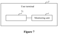
- the user equipment 70 may include: a receiving unit 71 and a monitoring unit 72.
- the receiving unit is configured to receive downlink control information in an n-th time slot.
- the monitoring unit is configured to perform the physical downlink control channel monitoring from a (n+X)-th time slot based on a switched physical downlink control channel monitoring state, in a case that the downlink control information includes switching indication information on the physical downlink control channel monitoring state, where n and X are both integers, and X is greater than or equal to 1.
- a value of X is determined based on a value of a minimum available scheduling delay activated and applied in a currently active downlink bandwidth part.
- the value of X is the minimum available scheduling delay or a greater one of the minimum available scheduling delay and Z, where a value of Z corresponds to a subcarrier spacing of the currently active downlink bandwidth part where the downlink control information is located; in a case that the minimum available scheduling delay is equal to 0, the value of X is 1 or Z.
- the value of Z is 1; and in a case that the subcarrier spacing of the currently active downlink bandwidth part where the downlink control information is located is 60Khz or 120Khz, the value of Z is 2.
- the value of X is a fixed value.
- a skipping duration of the physical downlink control channel monitoring indicated in the downlink control information is greater than the minimum available scheduling delay.
- the apparatus including the receiving unit 71 and the monitoring unit 72 may be, for example, a chip, a chip module, and the like.
- a computer readable storage medium is further provided according to an embodiment of the present disclosure.
- the computer readable storage medium has a computer program stored thereon.
- the computer program when being executed by a processor, implements steps of any one of the above methods.
- the computer readable storage medium may include: a ROM, a RAM, a magnetic disk or an optical disk, and the like.
- a user equipment is further provided according to an embodiment of the present disclosure.
- the user equipment includes a memory and a processor.
- the memory stores a computer program executable on the processor.
- the computer program is executed by the processor to implement steps of any one of the above methods.
- Each module/unit included in each apparatus and product described in the above-mentioned embodiments may be a software module/unit, a hardware module/unit, or a part of module/unit is a software module/unit and a part of module/unit is a hardware module/unit.
- each module/unit included therein may be implemented by hardware such as circuits, or at least some of the modules/units may be implemented by a software program running on the processor integrated inside the chip, the remaining (if any) part of the modules/units may be implemented by hardware such as circuits; for each apparatus and product applied to or integrated in the chip module, the modules/units included therein may be all implemented by hardware such as circuits, and different modules/units may be located in the same component (such as a chip, a circuit module, and the like) or in different components of the chip module, or at least some modules/units may be implemented by a software program running on the processor integrated inside the chip module, and the remaining (if any) part of the modules/units may be implemented by hardware such as circuits; for each apparatus and product applied to or integrated in the terminal, each module/unit included therein may be implemented by hardware such as circuits, and different modules/units may be located in the same component (such as a chip,
Landscapes
- Engineering & Computer Science (AREA)
- Signal Processing (AREA)
- Computer Networks & Wireless Communication (AREA)
- Physics & Mathematics (AREA)
- Mathematical Physics (AREA)
- Mobile Radio Communication Systems (AREA)
Abstract
Description
- The present application claims the priority to
Chinese Patent Application No. 202010232194.3, titled "PHYSICAL DOWNLINK CONTROL CHANNEL MONITORING METHOD, USER TERMINAL AND READABLE STORAGE MEDIUM", filed on March 27, 2020 - The present disclosure relates to the field of communication technology, and in particular to a method for monitoring a physical downlink control channel, a user equipment and a readable storage medium.
- The battery life of user equipment (UE) is an important aspect of user experience, which will affect the use experience of 5G user terminal or service.
- To this end, some technical features are introduced in the 5G system for indicating changes in user terminal behavior, such that the user terminal may be in a power saving state under appropriate conditions to save terminal power. This state switching involves a variety of configuration changes, which includes bandwidth part (BWP) switching (switching to BWP with a narrower bandwidth), parameter switching of a physical downlink control channel (PDCCH) search space (such as switching a monitoring periodicity to a larger periodicity), PDCCH monitoring skipping and using cross-slot scheduling with a minimum scheduling interval greater than 0, and the like.
- In the standard technology research of 5G new air interface (NR) in Release 16 version, the energy-saving technology part based on cross-slot scheduling is completed. In the upcoming research for Release 17 version, the technology of reducing PDCCH monitoring will be considered as one of the key technologies discussed.
- In the currently proposed method, the change of PDCCH monitoring behavior, such as changing PDCCH monitoring parameters (including periodicity, duration and offset), PDCCH skipping duration, and the like, is indicated based on downlink control information (DCI). However, there is no solution for when the user terminal starts to execute the indication information after receiving the DCI indicating the change of the PDCCH monitoring behavior.
- The problem to be solved by the present disclosure is to determine a time when the user terminal starts to switch the PDCCH monitoring behavior after receiving the DCI of the change of the PDCCH monitoring behavior.
- In order to solve the above problem, a method for monitoring a physical downlink control channel is provided according to an embodiment of the present disclosure. The method includes:
- receiving downlink control information in an n-th time slot; and
- performing, from a (n+X)-th time slot, physical downlink control channel monitoring based on a switched physical downlink control channel monitoring state, in a case that the downlink control information comprises switching indication information on the physical downlink control channel monitoring state, wherein n and X are integers, and X is greater than or equal to 1.
- In an embodiment, a value of X is determined based on a value of a minimum available scheduling delay activated and applied in a currently active downlink bandwidth part.
- In an embodiment, the value of X is determined based on the value of the minimum available scheduling delay activated in the currently active downlink bandwidth part by:
- in a case that the minimum available scheduling delay is greater than 0, setting the value of X to be the minimum available scheduling delay, or setting the value of X to be a greater of the minimum available scheduling delay and Z, where a value of Z corresponds to a subcarrier spacing of the currently active downlink bandwidth part where the downlink control information is located; and
in a case that the minimum available scheduling delay is equal to 0, setting the value ofXtobe 1 or Z. - In an embodiment, in a case that the subcarrier spacing of the currently active downlink bandwidth part where the downlink control information is located is 15Khz or 30Khz, the value of Z is 1; and in a case that the subcarrier spacing of the currently active downlink bandwidth part where the downlink control information is located is 60Khz or 120Khz, the value of Z is 2.
- In an embodiment, the value of X is a fixed value.
- In an embodiment, in a case that X is equal to 1, a skipping duration of the physical downlink control channel monitoring indicated by the downlink control information is greater than the minimum available scheduling delay.
- In an embodiment, the switching indication information on the physical downlink control channel monitoring state includes at least one of:
- skipping all or part of the physical downlink control channel monitoring in a time period; and
- switching a parameter of a physical downlink control channel search space.
- In an embodiment, the skipping all or part of the physical downlink control channel monitoring in a time period includes:
in a current discontinuous reception periodicity, not monitoring the physical downlink control channel. - A user equipment is further provided according to an embodiment of the present disclosure. The user equipment includes: a receiving unit and a monitoring unit.
- The receiving unit is configured to receive downlink control information in an n-th time slot.
- The monitoring unit is configured to perform physical downlink control channel monitoring from a (n+X)-th time slot, based on a switched physical downlink control channel monitoring state, in a case that the downlink control information comprises switching indication information on a physical downlink control channel monitoring state, wherein n and X are both integers, and X is greater than or equal to 1.
- In an embodiment, a value of X is determined based on a value of a minimum available scheduling delay activated and applied in a currently active downlink bandwidth part.
- In an embodiment, in a case that the minimum available scheduling delay is greater than 0, the value of X is set to be the minimum available scheduling delay, or a greater of the minimum available scheduling delay and Z, where a value of Z corresponds to a subcarrier spacing of the currently active downlink bandwidth part where the downlink control information is located; and in a case that the minimum available scheduling delay is equal to 0, the value of X is set to be 1 or Z.
- In an embodiment, in a case that the subcarrier spacing of the currently active downlink bandwidth part where the downlink control information is located is 15Khz or 30Khz, the value of Z is 1; and in a case that the subcarrier spacing of the currently active downlink bandwidth part where the downlink control information is located is 60Khz or 120Khz, the value of Z is 2.
- In an embodiment, the value of X is a fixed value.
- In an embodiment, in a case that X is equal to 1, a skipping duration of the physical downlink control channel monitoring indicated in the downlink control information is greater than the minimum available scheduling delay.
- A computer readable storage medium is further provided according to an embodiment of the present disclosure. The computer readable storage medium has a computer program stored thereon. The computer program, when being executed by a processor, implements steps of any one of the above methods.
- A user equipment is further provided according to an embodiment of the present disclosure. The user equipment includes a memory and a processor, where the memory stores a computer program capable of being executed on the processor. The computer program is executed by the processor to implement steps of any one of the above methods.
- Compared with the conventional technology, the technical solutions according to the embodiment of the present disclosure have the following advantages.
- With the above solution, when the downlink control information includes switching indication information on the physical downlink control channel monitoring state, the physical downlink control channel is monitored from a (n+X)-th time slot, based on the switched physical downlink control channel monitoring state. In this way, the physical downlink control channel can be monitored in the same bandwidth part scheduling process.
-
-
Figure 1 shows a schematic diagram of cross-slot scheduling; -
Figure 2 shows a flowchart of a method for monitoring a physical downlink control channel according to an embodiment of the present disclosure; -
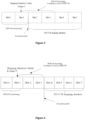
Figure 3 shows a schematic diagram of skipping of all or part of the PDCCH monitoring; -
Figure 4 shows a schematic diagram of not monitoring the physical downlink control channel during the current discontinuous reception periodicity; -
Figure 5 shows a schematic diagram of determining an execution point for performing PDCCH monitoring according to an embodiment of the present disclosure; -
Figure 6 shows a schematic diagram of determining an execution point for performing PDCCH monitoring according to another embodiment of the present disclosure; and -
Figure 7 shows a schematic structural diagram of user equipment according to an embodiment of the present disclosure. - The research on a first version of 5G mobile communication standard is completed in 2018. Based on the first version of the 5G standard, device manufacturers and operators may begin production of devices and deployment of 5G networks.
- In order to meet the performance requirements, many new technologies are introduced into the 5G system, such as a large transmission bandwidth, a large subcarrier spacing, a small processing unit, more antennas, and the like. However, due to the introduction of these technologies, the energy consumption of 5G user terminal increases several times compared with that of 4G user terminal.
- Since the volume and battery capacity per unit volume of the current user terminal have not been greatly improved, the battery life of 5G user terminal cannot meet the daily usage requirements, which greatly affects the user experience. To this end, the 3GPP standardization organization has established a 5G power saving item, hoping to discover technologies to save power consumption of the terminals to improve the problem of high power consumption of 5G terminals. The power saving of the user terminal can be carried out in many ways, which may include standardized contents and contents to be standardized.
- The standardized contents may include: a wake-up signal, and a restriction of cross-slot scheduling. The contents to be standardized include: switching of PDCCH monitoring state and the like.
- In order to facilitate the understanding of the following embodiments of the present disclosure, the cross-slot scheduling is briefly described below.
- Cross-slot scheduling refers to that a time slot in which scheduling information (that is DCI) is received, is not in the same time slot as the physical downlink shared channel (PDSCH) scheduled by the DCI. In long term evolution (LTE), the DCI and the scheduled PDSCH are in the same time slot. In order to improve the scheduling flexibility in 5G NR, the scheduled PDSCH may be located in the several time slots after the time slot where the DCI is located.
- The cross-slot scheduling under Release-15 is realized by configuring a time domain resource allocation (TDRA) table. The TDRA table is an indicator table with a maximum of 16 rows. As shown in Table 1, the first column represents a serial number, that is, the index. The second column represents the value of K0, where K0 is a scheduling delay used in scheduling of the PDSCH, that is, a time slot interval between the time slot for receiving the DCI and the scheduled PDSCH. For example, when K0 is equal to 1, the PDCCH is in the n-th time slot, and then the corresponding PDSCH is in the (n+1)-th time slot.
- The third column of the TDRA table represents a mapping type. A represents mapping based on a slot (which refers to that one slot is one scheduling unit, and the PDCCH is always located in the first 1, 2 or 3 symbols of a slot). B represents mapping based on a mini-slot (which refers to that several symbols forms one scheduling unit, and the starting position of PDCCH is not limited to the first symbol in the slot based on the number of symbols in the mini-slot, for example, if the mini-slot length is 7 symbols, the PDCCH may be located at the first symbol or at the 8-th symbol).
- The fourth column of the TDRA table represents a start symbol and a length indication (Start and Length Indication Value, SLIV). The value shown in this column indicates the start symbol position of the PDSCH and the duration symbol length of the PDSCH.
Table 1 Index K0 Type SLIV 0 0 A/ B XXX 1 1 A 56 2 4 A/ B XXX 3 6 A/B XXX ... ... ... ... 15 32 A/B XXX - For example, when the index is equal to 1, K0 is equal to 1, type is equal to A, and SLIV is equal to 56, the schematic diagram of cross-slot scheduling may refer to
Figure 1 . - From the perspective of power saving, cross-slot scheduling may allow the LTE to avoid unnecessary PDSCH buffering, and may use a narrower PDCCH receiving bandwidth to save equipment power consumption. However, the K0 in the TDRA table configured for the current cross-slot scheduling may be equal to 0 and greater than 0. If K0 is configured to be equal to 0, the UE does not determine whether the K0 of the current time slot is greater than 0 or equal to 0. In this case, the PDSCH needs to be buffered all the time.
- In the new version Release-16, the minimum available scheduling delay (KOmin) may be indicated to be greater than 0. When K0 is always greater than 0, the UE may be kept in the state of cross-slot scheduling to save power. For the indication and switching of KOmin, an application delay of a new KOmin is introduced, in consideration of the receiving time and processing time of PDCCH and the adjusting time of related modules. For example, when the current minimum available scheduling delay KOmin is equal to 4, that is, the starting position of the PDSCH scheduled by DCI is located at a slot position of the time slot where the DCI is located plus 4. In this way, the LTE may perform the DCI processing in 4 time slots, that is, decoding the PDCCH before the slot where the PDSCH is located at the earliest, rather than several slots. If the DCI is received in a
time slot 0, the DCI may be decoded before thetime slot 4. Whether the processing may be relaxed to the time slot position corresponding to KOmin depends on the UE implementation. In the case of no other processing timelines to be satisfied, there are some opportunities to do such level of relaxation. Relaxing the DCI processing may reduce the clock frequency and voltage of the processing module, which is extremely helpful for reducing LTE power consumption. - In the currently proposed methods for monitoring a PDCCH channel, changes in PDCCH monitoring, such as changing PDCCH search space parameters (including periodicity, duration and offset), PDCCH skipping duration and the like, are indicated based on downlink control information (DCI). However, there is no solution for when the user terminal starts to execute the indication information after receiving the DCI indicating the change of the PDCCH monitoring behavior.
- In view of the above problems, a method for monitoring a physical downlink control channel is provided according to an embodiment of the present disclosure. In the method, when the downlink control information includes switching indication information on the physical downlink control channel monitoring state, the physical downlink control channel is monitored from a (n+X)-th time slot, based on the switched physical downlink control channel monitoring state. In this way, the physical downlink control channel can be monitored in the same bandwidth part scheduling process.
- In order to make the above objectives, features and advantages of the present disclosure more apparent and easy to be understood, embodiments of the present disclosure will be described in detail hereinafter in conjunction with the drawings.
- Referring to
Figure 2 , a method for monitoring a physical downlink control channel is provided according to an embodiment of the present disclosure. The method may include step 21 and step 22. - In step 21, downlink control information is received in the n-th time slot.
- In an embodiment of the present disclosure, the physical downlink shared channel (PDSCH) scheduled by the DCI is the same BWP scheduling. That is, the BWP where the PDSCH scheduled by the DCI is located is the same as the current active BWP where the DCI is located. The BWP where the PDSCH scheduled by the DCI is located may be obtained by the UE from the DCI, that is, is indicated by the base station through the DCI.
- In step 22, in the case that the downlink control information includes switching indication information on a physical downlink control channel monitoring state, physical downlink control channel monitoring is performed from the (n+X)-th time slot based on the switched physical downlink control channel monitoring state; where n and X are both integers, and X is greater than or equal to 1.
- In a specific implementation, the DCI may include switching indication information on the PDCCH monitoring state, which is used to instruct UE to switch the PDCCH monitoring state. The DCI may not include the switching indication information on the PDCCH monitoring state. Accordingly, the UE does not need to switch the PDCCH monitoring state.
- In an embodiment of the present disclosure, the switching indication information on the PDCCH monitoring state may only include: skipping of all or part of the PDCCH monitoring in a time period (PDCCH skipping). The switching indication information on the PDCCH monitoring state may only include: parameter switching of a PDCCH search space (SS). The switching indication information on the PDCCH monitoring state may include both skipping of all or part of the PDCCH monitoring in the time period and parameter switching the PDCCH search space.
- The skipping of all or part of the PDCCH monitoring in the time period means that the UE does not receive and blindly decode the PDCCH in the time period. Taking the periodicity of PDCCH as one time slot as an example, referring to
Figure 3 , it is assumed that the UE receives a PDCCH skipping instruction in the n-th time slot. The instruction indicates that the skipping duration of PDCCH monitoring is 3 time slots (or indicates that the skipping duration is an absolute time length, such as 5ms), and this instruction is executed in the next time slot (with a delay of 1 slot). Therefore, the UE will not receive and blindly decode the PDCCH in (n+1)-th to (n+3)-th time slots, and restart to receive PDCCH on arrival at the (n+4)-th time slot. In this way, the base station may make the terminal enter a sleep state in which the PDCCH is not received, in the case of no data scheduling in a short time, so as to save the power of the terminal. - In an embodiment of the present disclosure, the skipping of all or part of the physical downlink control channel monitoring in the time period may include: in a current discontinuous reception (DRX) periodicity, not monitoring the physical downlink control channel, which means that the indicated skipping duration of PDCCH monitoring is the remaining active part of the current DRX periodicity. For example, referring to
Figure 4 , when the PDCCH indication information for indicating the skipping of PDCCH monitoring in the current DRX periodicity is received in a certain time slot in the current DRX periodicity, the PDCCH is not be monitored in the current DRX periodicity until the start time slot of the next DRX periodicity. - In a specific implementation, the parameter of the PDCCH search space is switched. For example, the search space of the LTE before the switching is configured as: a periodicity of 20ms, a monitoring duration of 5ms, and an offset of 5ms. After the switching, the search space of the LTE is configured as: the period of 50ms, the monitoring duration of 10ms, and the offset of 0ms. The LTE receives the switching instruction in the n-th time slot; and monitors the PDCCH with the switched parameters of the search space, from the (n+X)-th time slot.
- In a specific implementation, the switching of the PDCCH monitoring state may further include not monitoring certain DCI formats, or not monitoring certain control information sets, and the like.
- In a specific implementation, when the PUSCH is scheduled in the same BWP, the value of X may be set in various methods.
- In an embodiment of the present disclosure, the value of X is a fixed value. For example, X is set to be equal to 1. That is, the UE may monitor the PDCCH from the (n+1)-th time slot, based on the switched PDCCH monitoring state.
- Referring to
Figure 5 , it is assumed that the LTE receives DCI in a time slot Slot!. The DCI indicates that the skipping duration of PDCCH monitoring is 4 time slots, and the minimum available scheduling delay KOmin when the PDSCH is scheduled is equal to 3. Therefore, the time slot Slot2 may be used as an execution point for executing the PDCCH monitoring based on the switched PDCCH monitoring state. - The inventor further found that when the base station sends an instruction for skipping the PDCCH monitoring to the terminal in the time slot Slot1, since the execution point is the next time slot and the skipping duration of PDCCH monitoring is 4 time slots, the base station does not transmit PDCCH in the time slots Slot2, Slot3, Slot4 and Slot5.
- However, on the UE side, since the current KOmin is equal to 3, the terminal may relax the processing of the PDCCH, and the UE needs to decode and obtain the DCI carrying the instruction for skipping the PDCCH monitoring in the time slot Slot3. During the DCI decoding process, the LTE does not know whether the DCI includes the indication for skipping the PDCCH monitoring. Therefore, the UE needs to continue to receive the PDCCH in the time slots Slot2 and Slot3, which is an unnecessary blind decoding for the UE.
- In addition, after decoding the DCI in Slot3, the LTE finds that the indication for skipping the PDCCH monitoring needs to be executed, the execution point is the
time slot 2 and the skipping duration of PDCCH monitoring is 4. The UE no longer monitors the PDCCH in the time slots Slot4 and SlotS. In this case, the terminal actually skips the PDCCH for only 2 time slots. If the skipping duration of PDCCH monitoring is less than the minimum available scheduling delay KOmin, the UE is beyond the skipping duration of PDCCH monitoring when decoding the indication for skipping the PDCCH monitoring. When the UE decodes and obtains the PDCCH, the skipping duration of PDCCH monitoring has ended, and the UE needs to wake up to monitor the PDCCH. In this case, skipping the PDCCH becomes an invalid behavior. - In order to avoid the above situation, in an embodiment of the present disclosure, the skipping duration of PDCCH monitoring indicated in the DCI is greater than the minimum available scheduling delay KOmin, such that skipping the PDCCH may be prevented from becoming an invalid behavior, thereby reducing LTE power consumption.
- In order to avoid the above situation, when the execution point is the next time slot of a time slot in which the DCI is received, the UE cannot relax the PDCCH processing. In this case, even if KOmin is limited to a non-zero value, the terminal still needs to complete the decoding of the PDCCH in the time slot in which the PDCCH is received. But in this way, the acquisition of the power saving gain is limited.
- In order to avoid limiting the acquisition of power saving gain and avoid skipping the PDCCH from becoming an invalid behavior, in an embodiment of the present disclosure, the value of X may be determined based on a value of a minimum available scheduling delay KOmin activated and applied in a currently active downlink BWP.
- In an embodiment of the present disclosure, when the minimum available scheduling delay KOmin is greater than 0, the value of X is equal to the minimum available scheduling delay KOmin. That is, in the case of KOmin > 0, X = KOmin.
- In an embodiment of the present disclosure, when minimum available scheduling delay KOmin is greater than 0, the value of X may be a greater one of the minimum available scheduling delay KOmin and Z. That is, in the case of KOmin > 0, X = Max (KOmin, Z).
- A value of Z corresponds to a subcarrier spacing of the currently active downlink BWP where the DCI is located. When the subcarrier spacing of the currently active downlink BWP where the DCI is located is 15Khz, the value of Z is 1. When the subcarrier spacing of the currently active downlink BWP where the DCI is located is 30Khz, the value of Z is 1. When the subcarrier spacing of the currently active downlink BWP where the DCI is located is 60Khz, the value of Z is 2. When the subcarrier spacing of the currently active downlink BWP where the DCI is located is 120Khz, the value of Z is 2.
- For example, when the subcarrier spacing of the currently active downlink BWP where the DCI is located is 60Khz, Z = 2, and X = Max (KOmin, 2). If KOmin > 2, X = KOmin. In this case, the UE may monitor the physical downlink control channel from the (n+K0min)-th time slot, based on the switched physical downlink control channel monitoring state.
- If KOmin < 2, X = 2. In this case, the LTE may monitor the physical downlink control channel from the (n+2)-th time slot based on the switched physical downlink control channel monitoring state.
- Taking X = KOmin as an example, referring to
Figure 6 , it is assumed that the UE receives DCI in the time slot Slot1. The DCI indicates that the skipping duration of PDCCH monitoring is 4 time slots, and the minimum available time for scheduling the PDSCH KOmin is equal to 3. In this case, the time slot Slot4 may be used as an execution point for executing the PDCCH monitoring based on the switched PDCCH monitoring state. - Since the skipping duration of PDCCH monitoring is not yet started when the UE decodes the indication for skipping the PDCCH monitoring, the behavior of the UE continuing to receive PDCCH in the time slots Slot2 and Slot3 is not an unnecessary blind decoding, and the LTE skipping PDCCH becomes an invalid behavior.
- Similarly, when X = Max (KOmin, Z), the above effect can also be achieved.
- In another embodiment of the present disclosure, when the minimum available scheduling delay KOmin is equal to 0, the value of X is 1. That is, when KOmin = 0, X = 1. The LTE may monitor the physical downlink control channel from the (n+1)-th time slot, based on the switched physical downlink control channel monitoring state. For example, the LTE may skip all or part of the PDCCH monitoring, from the (n+1)-th time slot.
- In another embodiment of the present disclosure, when the minimum available scheduling delay KOmin is equal to 0, the value of X is Z. That is, when KOmin = 0, X = Z. The LTE may monitor the physical downlink control channel from the (n+Z)-th time slot, based on the switched physical downlink control channel monitoring state. For example, the LTE may switch the parameter of the PDCCH search space, from the (n+Z)-th time slot.
- It can be understood that, in a specific implementation, the method for monitoring the physical downlink control channel may be implemented by a software program, and the software program runs in a processor integrated in a chip or a chip module.
- It should be noted from the above content that, in the method for monitoring the physical downlink control channel according to the embodiment of the present disclosure, when the same BWP is scheduled, in the case that the downlink control information includes switching indication information on the physical downlink control channel monitoring state, the physical downlink control channel is monitored from the (n+X)-th time slot, based on the switched physical downlink control channel monitoring state. In this way, the monitoring of the physical downlink control channel may be monitored in the same bandwidth part scheduling process.
- In order for those skilled in the art to better understand and implement the present disclosure, an apparatuses and a computer readable storage medium corresponding to the above method are described in detail below.
- Referring to
Figure 7 , a user equipment 70 is further provided according to an embodiment of the present disclosure. The user equipment 70 may include: a receivingunit 71 and a monitoring unit 72. - The receiving unit is configured to receive downlink control information in an n-th time slot.
- The monitoring unit is configured to perform the physical downlink control channel monitoring from a (n+X)-th time slot based on a switched physical downlink control channel monitoring state, in a case that the downlink control information includes switching indication information on the physical downlink control channel monitoring state, where n and X are both integers, and X is greater than or equal to 1.
- In an embodiment of the present disclosure, a value of X is determined based on a value of a minimum available scheduling delay activated and applied in a currently active downlink bandwidth part.
- In an embodiment of the present disclosure, in a case that the minimum available scheduling delay is greater than 0, the value of X is the minimum available scheduling delay or a greater one of the minimum available scheduling delay and Z, where a value of Z corresponds to a subcarrier spacing of the currently active downlink bandwidth part where the downlink control information is located; in a case that the minimum available scheduling delay is equal to 0, the value of X is 1 or Z.
- In an embodiment of the present disclosure, in a case that the subcarrier spacing of the currently active downlink bandwidth part where the downlink control information is located is 15Khz or 30Khz, the value of Z is 1; and in a case that the subcarrier spacing of the currently active downlink bandwidth part where the downlink control information is located is 60Khz or 120Khz, the value of Z is 2.
- In an embodiment of the present disclosure, the value of X is a fixed value.
- In an embodiment of the present disclosure, in a case that X is equal to 1, a skipping duration of the physical downlink control channel monitoring indicated in the downlink control information is greater than the minimum available scheduling delay.
- The apparatus (virtual apparatus) including the receiving
unit 71 and the monitoring unit 72 may be, for example, a chip, a chip module, and the like. - A computer readable storage medium is further provided according to an embodiment of the present disclosure. The computer readable storage medium has a computer program stored thereon. The computer program, when being executed by a processor, implements steps of any one of the above methods.
- In a specific implementation, the computer readable storage medium may include: a ROM, a RAM, a magnetic disk or an optical disk, and the like.
- A user equipment is further provided according to an embodiment of the present disclosure. The user equipment includes a memory and a processor. The memory stores a computer program executable on the processor. The computer program is executed by the processor to implement steps of any one of the above methods.
- Each module/unit included in each apparatus and product described in the above-mentioned embodiments may be a software module/unit, a hardware module/unit, or a part of module/unit is a software module/unit and a part of module/unit is a hardware module/unit. For example, for each apparatus or product applied to or integrated in a chip, each module/unit included therein may be implemented by hardware such as circuits, or at least some of the modules/units may be implemented by a software program running on the processor integrated inside the chip, the remaining (if any) part of the modules/units may be implemented by hardware such as circuits; for each apparatus and product applied to or integrated in the chip module, the modules/units included therein may be all implemented by hardware such as circuits, and different modules/units may be located in the same component (such as a chip, a circuit module, and the like) or in different components of the chip module, or at least some modules/units may be implemented by a software program running on the processor integrated inside the chip module, and the remaining (if any) part of the modules/units may be implemented by hardware such as circuits; for each apparatus and product applied to or integrated in the terminal, each module/unit included therein may be implemented by hardware such as circuits, and different modules/units may be located in the same component (such as a chip, a circuit module, and the like) or in different components of the terminal, or at least some of the modules/units may be implemented by a software program running on the processor integrated inside the terminal, and the remaining (if any) part of the modules/units may be implemented by hardware such as circuits.
- Although the present disclosure is disclosed as above, the present disclosure is not limited thereto. Any person skilled in the art can make various changes and modifications without departing from the spirit and scope of the present disclosure. Therefore, the protection scope of the present disclosure should be defined by the claims.
Claims (16)
- A method for monitoring a physical downlink control channel, comprising:receiving downlink control information in an n-th time slot; andperforming physical downlink control channel monitoring from a (n+X)-th time slot, based on a switched physical downlink control channel monitoring state, in a case that the downlink control information comprises switching indication information on a physical downlink control channel monitoring state; wherein n and X are both integers, and X is greater than or equal to 1.
- The method for monitoring the physical downlink control channel according to claim 1, wherein the value of X is determined based on a value of a minimum available scheduling delay activated and applied in a currently active downlink bandwidth part.
- The method for monitoring the physical downlink control channel according to claim 2, wherein the value of X is determined based on the value of the minimum available scheduling delay activated in the currently active downlink bandwidth part by:in a case that the minimum available scheduling delay is greater than 0, the value of X is the minimum available scheduling delay, or a greater of the minimum available scheduling delay and Z, wherein a value of Z corresponds to a subcarrier spacing of the currently active downlink bandwidth part where the downlink control information is located; andin a case that the minimum available scheduling delay is equal to 0, the value of X is 1 or Z.
- The method for monitoring the physical downlink control channel according to claim 3, wherein in a case that the subcarrier spacing of the currently active downlink bandwidth part where the downlink control information is located is 15Khz or 30Khz, the value of Z is 1; and in a case that the subcarrier spacing of the currently active downlink bandwidth part where the downlink control information is located is 60Khz or 120Khz, the value of Z is 2.
- The method for monitoring the physical downlink control channel according to claim 1, wherein the value of X is a fixed value.
- The method for monitoring the physical downlink control channel according to claim 5, wherein in a case that X is equal to 1, a skipping duration of the physical downlink control channel monitoring indicated in the downlink control information is greater than a minimum available scheduling delay.
- The method for monitoring the physical downlink control channel according to claim 1, wherein the switching indication information on the monitoring state of the physical downlink control channel comprises at least one of:skipping all or part of the physical downlink control channel monitoring in a time period; andswitching a parameter of a physical downlink control channel search space.
- The method for monitoring the physical downlink control channel according to claim 7, wherein the skipping all or part of the physical downlink control channel monitoring in the time period comprises:
during a current discontinuous reception periodicity, not monitoring the physical downlink control channel. - A user equipment, comprising:a receiving unit configured to receive downlink control information in an n-th time slot; anda monitoring unit configured to perform physical downlink control channel monitoring from a (n+X)-th time slot, based on a switched physical downlink control channel monitoring state, in a case that the downlink control information comprises switching indication information on a physical downlink control channel monitoring state; wherein n and X are both integers, and X is greater than or equal to 1.
- The user equipment according to claim 9, wherein the value of X is determined based on a value of a minimum available scheduling delay activated and applied in a currently active downlink bandwidth part.
- The user equipment according to claim 10, wherein in a case that the minimum available scheduling delay is greater than 0, the value of X is the minimum available scheduling delay, or a greater of the minimum available scheduling delay and Z, wherein a value of Z corresponds to a subcarrier spacing of the currently active downlink bandwidth part where the downlink control information is located, and
in a case that the minimum available scheduling delay is equal to 0, the value of X is 1 or Z. - The user equipment according to claim 11, wherein in a case that the subcarrier spacing of the currently active downlink bandwidth part where the downlink control information is located is 15Khz or 30Khz, the value of Z is 1; and in a case that the subcarrier spacing of the currently active downlink bandwidth part where the downlink control information is located is 60Khz or 120Khz, the value of Z is 2.
- The user equipment according to claim 9, wherein the value of X is a fixed value.
- The user equipment according to claim 13, wherein in a case that X is equal to 1, a skipping duration of the physical downlink control channel monitoring indicated in the downlink control information is greater than a minimum available scheduling delay.
- A computer readable storage medium having a computer program stored thereon, wherein the computer program, when being executed by a processor, implements steps of the method according to any one of claims 1 to 8.
- A user equipment, comprising:a memory; anda processor,wherein the memory stores a computer program executable on the processor, wherein the computer program is executed by the processor to implement steps of the method according to any one of claims 1 to 8.
Applications Claiming Priority (2)
| Application Number | Priority Date | Filing Date | Title |
|---|---|---|---|
| CN202010232194.3A CN113453322B (en) | 2020-03-27 | 2020-03-27 | Physical downlink control channel monitoring method, user terminal and readable storage medium |
| PCT/CN2021/082527 WO2021190522A1 (en) | 2020-03-27 | 2021-03-24 | Physical downlink control channel monitoring method, user terminal and readable storage medium |
Publications (3)
| Publication Number | Publication Date |
|---|---|
| EP4132117A1 true EP4132117A1 (en) | 2023-02-08 |
| EP4132117A4 EP4132117A4 (en) | 2023-08-30 |
| EP4132117B1 EP4132117B1 (en) | 2026-02-25 |
Family
ID=77808231
Family Applications (1)
| Application Number | Title | Priority Date | Filing Date |
|---|---|---|---|
| EP21774050.5A Active EP4132117B1 (en) | 2020-03-27 | 2021-03-24 | Physical downlink control channel monitoring method, user terminal and readable storage medium |
Country Status (4)
| Country | Link |
|---|---|
| US (1) | US12452874B2 (en) |
| EP (1) | EP4132117B1 (en) |
| CN (1) | CN113453322B (en) |
| WO (1) | WO2021190522A1 (en) |
Families Citing this family (10)
| Publication number | Priority date | Publication date | Assignee | Title |
|---|---|---|---|---|
| US11438960B2 (en) * | 2020-03-29 | 2022-09-06 | PanPsy Technologies, LLC | Enhanced power saving processes |
| MX2023001112A (en) * | 2020-07-28 | 2023-02-22 | Ericsson Telefon Ab L M | Reducing power consumption for pdcch monitoring. |
| WO2023065331A1 (en) * | 2021-10-22 | 2023-04-27 | 北京小米移动软件有限公司 | Information transmission method and apparatus, information receiving method and apparatus, and device and storage medium |
| WO2023130395A1 (en) * | 2022-01-07 | 2023-07-13 | 北京小米移动软件有限公司 | Channel monitoring method and apparatus, and device and storage medium |
| US20250081203A1 (en) * | 2022-01-07 | 2025-03-06 | Beijing Xiaomi Mobile Software Co., Ltd. | Monitoring method and device, and readable storage medium |
| CN116471620B (en) * | 2022-01-11 | 2026-01-23 | 大唐移动通信设备有限公司 | Physical Downlink Control Channel (PDCCH) monitoring method, device, equipment and storage medium |
| WO2023143550A1 (en) * | 2022-01-29 | 2023-08-03 | 维沃移动通信有限公司 | Channel monitoring method, terminal and network side device |
| CN119014048B (en) * | 2022-04-22 | 2025-11-04 | 中兴通讯股份有限公司 | Methods, apparatus and systems for resource management in wireless networks |
| WO2023207927A1 (en) * | 2022-04-28 | 2023-11-02 | 华为技术有限公司 | Energy-saving method and apparatus, and storage medium |
| WO2023240538A1 (en) * | 2022-06-16 | 2023-12-21 | 北京小米移动软件有限公司 | Method and apparatus for transmitting configuration information, and readable storage medium |
Family Cites Families (12)
| Publication number | Priority date | Publication date | Assignee | Title |
|---|---|---|---|---|
| WO2011129610A2 (en) * | 2010-04-13 | 2011-10-20 | 엘지전자 주식회사 | Method and device for receiving downlink signal |
| US10708938B2 (en) | 2016-10-31 | 2020-07-07 | Samsung Electronics Co., Ltd. | Transmission of UL control channels with dynamic structures |
| CN109429258B (en) * | 2017-07-17 | 2021-10-29 | 中国移动通信有限公司研究院 | Indication method, monitoring method, terminal and network side device for channel monitoring |
| US11611468B2 (en) * | 2017-09-28 | 2023-03-21 | Comcast Cable Communications, Llc | Beam management with DRX configuration |
| CN111357389B (en) | 2017-11-17 | 2024-03-12 | 诺基亚技术有限公司 | Control monitoring after receipt of discontinuous receive trigger |
| CN113038581A (en) | 2017-12-25 | 2021-06-25 | 维沃移动通信有限公司 | Control channel monitoring method, monitoring indication method, terminal and network equipment |
| CN110380831B (en) * | 2018-04-03 | 2022-05-17 | 中兴通讯股份有限公司 | A transmission method and device |
| US11330575B2 (en) | 2018-07-17 | 2022-05-10 | Samsung Electronics Co., Ltd. | Adaptation of communication parameters for a user equipment |
| CN112042143B (en) * | 2018-09-21 | 2022-03-18 | Oppo广东移动通信有限公司 | Monitoring method, device, equipment and system of PDCCH (physical Downlink control channel) |
| US11483767B2 (en) * | 2019-02-15 | 2022-10-25 | Mediatek Inc. | Cross-slot scheduling for power saving in mobile communications |
| WO2020252705A1 (en) * | 2019-06-19 | 2020-12-24 | Oppo广东移动通信有限公司 | Method and apparatus for controlling communication state, terminal, and network device |
| CN116318579B (en) * | 2020-02-14 | 2026-02-27 | 中兴通讯股份有限公司 | Power saving method for mobile station |
-
2020
- 2020-03-27 CN CN202010232194.3A patent/CN113453322B/en active Active
-
2021
- 2021-03-24 WO PCT/CN2021/082527 patent/WO2021190522A1/en not_active Ceased
- 2021-03-24 US US17/914,975 patent/US12452874B2/en active Active
- 2021-03-24 EP EP21774050.5A patent/EP4132117B1/en active Active
Also Published As
| Publication number | Publication date |
|---|---|
| CN113453322A (en) | 2021-09-28 |
| EP4132117A4 (en) | 2023-08-30 |
| CN113453322B (en) | 2022-08-12 |
| US20230146873A1 (en) | 2023-05-11 |
| US12452874B2 (en) | 2025-10-21 |
| WO2021190522A1 (en) | 2021-09-30 |
| EP4132117B1 (en) | 2026-02-25 |
Similar Documents
| Publication | Publication Date | Title |
|---|---|---|
| EP4132117B1 (en) | Physical downlink control channel monitoring method, user terminal and readable storage medium | |
| US12170959B2 (en) | Terminal power saving method, power saving apparatus, information sending method and apparatus, storage medium, and electronic device | |
| US12250748B2 (en) | Communication method and apparatus | |
| CN113453354B (en) | Physical downlink control channel monitoring method, user terminal and readable storage medium | |
| EP3836636A1 (en) | Reception configuration method and apparatus, reception control method and apparatus, terminal, base station, and storage medium | |
| CN115190500A (en) | Transmission processing method, terminal and network side equipment | |
| KR20220140720A (en) | Power Saving Methods for Mobile Stations | |
| WO2020038334A1 (en) | Information sending and receiving method, and communication device | |
| EP4027559A1 (en) | Communication method and apparatus | |
| CN115066933B (en) | Control channel monitoring method | |
| US20240089958A1 (en) | Method, device, and system for uplink signaling transmission | |
| EP4387340A1 (en) | Method and apparatus for information monitoring | |
| EP4401473A1 (en) | Method for stopping monitoring physical downlink control channel and communication apparatus | |
| JP2022517197A (en) | Resource setting method, resource acquisition method, network equipment and terminals | |
| KR102094774B1 (en) | Methods for controlling SCell state and Apparatuses thereof | |
| US12309701B2 (en) | Method and device for determining parameter of power saving signal, terminal and storage medium | |
| WO2022147770A1 (en) | Method and apparatus for monitoring physical downlink control channels | |
| CN111867011B (en) | Energy-saving signal transmission method, network side equipment and user equipment | |
| CN114080033A (en) | Method for reducing physical downlink control channel monitoring, user equipment and storage medium | |
| CA3143610C (en) | Terminal power saving method, power saving apparatus, information sending method and apparatus, storage medium, and electronic device | |
| EP4604626A1 (en) | Method and device for performing wireless communication using low power receiver | |
| KR20250023304A (en) | Method and apparatus for performing wireless communication with low power wakeup receiver | |
| KR20250007989A (en) | Method and apparatus for performing wireless communication with low power wakeup receiver | |
| KR20250126613A (en) | Method and apparatus for performing wireless communication with low power wakeup receiver | |
| KR20260025911A (en) | Method and apparatus for providing base station interface |
Legal Events
| Date | Code | Title | Description |
|---|---|---|---|
| STAA | Information on the status of an ep patent application or granted ep patent |
Free format text: STATUS: THE INTERNATIONAL PUBLICATION HAS BEEN MADE |
|
| PUAI | Public reference made under article 153(3) epc to a published international application that has entered the european phase |
Free format text: ORIGINAL CODE: 0009012 |
|
| STAA | Information on the status of an ep patent application or granted ep patent |
Free format text: STATUS: REQUEST FOR EXAMINATION WAS MADE |
|
| 17P | Request for examination filed |
Effective date: 20221021 |
|
| AK | Designated contracting states |
Kind code of ref document: A1 Designated state(s): AL AT BE BG CH CY CZ DE DK EE ES FI FR GB GR HR HU IE IS IT LI LT LU LV MC MK MT NL NO PL PT RO RS SE SI SK SM TR |
|
| DAV | Request for validation of the european patent (deleted) | ||
| DAX | Request for extension of the european patent (deleted) | ||
| A4 | Supplementary search report drawn up and despatched |
Effective date: 20230802 |
|
| RIC1 | Information provided on ipc code assigned before grant |
Ipc: H04W 52/02 20090101AFI20230727BHEP |
|
| GRAP | Despatch of communication of intention to grant a patent |
Free format text: ORIGINAL CODE: EPIDOSNIGR1 |
|
| STAA | Information on the status of an ep patent application or granted ep patent |
Free format text: STATUS: GRANT OF PATENT IS INTENDED |
|
| INTG | Intention to grant announced |
Effective date: 20250915 |
|
| GRAS | Grant fee paid |
Free format text: ORIGINAL CODE: EPIDOSNIGR3 |
|
| GRAA | (expected) grant |
Free format text: ORIGINAL CODE: 0009210 |
|
| STAA | Information on the status of an ep patent application or granted ep patent |
Free format text: STATUS: THE PATENT HAS BEEN GRANTED |
|
| AK | Designated contracting states |
Kind code of ref document: B1 Designated state(s): AL AT BE BG CH CY CZ DE DK EE ES FI FR GB GR HR HU IE IS IT LI LT LU LV MC MK MT NL NO PL PT RO RS SE SI SK SM TR |
|
| REG | Reference to a national code |
Ref country code: CH Ref legal event code: F10 Free format text: ST27 STATUS EVENT CODE: U-0-0-F10-F00 (AS PROVIDED BY THE NATIONAL OFFICE) Effective date: 20260225 Ref country code: GB Ref legal event code: FG4D |
|
| REG | Reference to a national code |
Ref country code: DE Ref legal event code: R096 Ref document number: 602021048722 Country of ref document: DE |
|
| REG | Reference to a national code |
Ref country code: IE Ref legal event code: FG4D |
|
| PGFP | Annual fee paid to national office [announced via postgrant information from national office to epo] |
Ref country code: DE Payment date: 20260330 Year of fee payment: 6 |