EP4131673A1 - Lead block and rotary connector device - Google Patents
Lead block and rotary connector device Download PDFInfo
- Publication number
- EP4131673A1 EP4131673A1 EP21781578.6A EP21781578A EP4131673A1 EP 4131673 A1 EP4131673 A1 EP 4131673A1 EP 21781578 A EP21781578 A EP 21781578A EP 4131673 A1 EP4131673 A1 EP 4131673A1
- Authority
- EP
- European Patent Office
- Prior art keywords
- lead block
- additional
- exposed
- cut surface
- block body
- Prior art date
- Legal status (The legal status is an assumption and is not a legal conclusion. Google has not performed a legal analysis and makes no representation as to the accuracy of the status listed.)
- Pending
Links
Images






Classifications
-
- H—ELECTRICITY
- H01—ELECTRIC ELEMENTS
- H01R—ELECTRICALLY-CONDUCTIVE CONNECTIONS; STRUCTURAL ASSOCIATIONS OF A PLURALITY OF MUTUALLY-INSULATED ELECTRICAL CONNECTING ELEMENTS; COUPLING DEVICES; CURRENT COLLECTORS
- H01R35/00—Flexible or turnable line connectors, i.e. the rotation angle being limited
- H01R35/02—Flexible line connectors without frictional contact members
- H01R35/025—Flexible line connectors without frictional contact members having a flexible conductor wound around a rotation axis
-
- H—ELECTRICITY
- H01—ELECTRIC ELEMENTS
- H01R—ELECTRICALLY-CONDUCTIVE CONNECTIONS; STRUCTURAL ASSOCIATIONS OF A PLURALITY OF MUTUALLY-INSULATED ELECTRICAL CONNECTING ELEMENTS; COUPLING DEVICES; CURRENT COLLECTORS
- H01R35/00—Flexible or turnable line connectors, i.e. the rotation angle being limited
- H01R35/04—Turnable line connectors with limited rotation angle with frictional contact members
-
- B—PERFORMING OPERATIONS; TRANSPORTING
- B29—WORKING OF PLASTICS; WORKING OF SUBSTANCES IN A PLASTIC STATE IN GENERAL
- B29C—SHAPING OR JOINING OF PLASTICS; SHAPING OF MATERIAL IN A PLASTIC STATE, NOT OTHERWISE PROVIDED FOR; AFTER-TREATMENT OF THE SHAPED PRODUCTS, e.g. REPAIRING
- B29C45/00—Injection moulding, i.e. forcing the required volume of moulding material through a nozzle into a closed mould; Apparatus therefor
- B29C45/14—Injection moulding, i.e. forcing the required volume of moulding material through a nozzle into a closed mould; Apparatus therefor incorporating preformed parts or layers, e.g. injection moulding around inserts or for coating articles
- B29C45/14639—Injection moulding, i.e. forcing the required volume of moulding material through a nozzle into a closed mould; Apparatus therefor incorporating preformed parts or layers, e.g. injection moulding around inserts or for coating articles for obtaining an insulating effect, e.g. for electrical components
-
- B—PERFORMING OPERATIONS; TRANSPORTING
- B60—VEHICLES IN GENERAL
- B60R—VEHICLES, VEHICLE FITTINGS, OR VEHICLE PARTS, NOT OTHERWISE PROVIDED FOR
- B60R16/00—Electric or fluid circuits specially adapted for vehicles and not otherwise provided for; Arrangement of elements of electric or fluid circuits specially adapted for vehicles and not otherwise provided for
- B60R16/02—Electric or fluid circuits specially adapted for vehicles and not otherwise provided for; Arrangement of elements of electric or fluid circuits specially adapted for vehicles and not otherwise provided for electric constitutive elements
- B60R16/023—Electric or fluid circuits specially adapted for vehicles and not otherwise provided for; Arrangement of elements of electric or fluid circuits specially adapted for vehicles and not otherwise provided for electric constitutive elements for transmission of signals between vehicle parts or subsystems
- B60R16/027—Electric or fluid circuits specially adapted for vehicles and not otherwise provided for; Arrangement of elements of electric or fluid circuits specially adapted for vehicles and not otherwise provided for electric constitutive elements for transmission of signals between vehicle parts or subsystems between relatively movable parts of the vehicle, e.g. between steering wheel and column
-
- H—ELECTRICITY
- H01—ELECTRIC ELEMENTS
- H01R—ELECTRICALLY-CONDUCTIVE CONNECTIONS; STRUCTURAL ASSOCIATIONS OF A PLURALITY OF MUTUALLY-INSULATED ELECTRICAL CONNECTING ELEMENTS; COUPLING DEVICES; CURRENT COLLECTORS
- H01R13/00—Details of coupling devices of the kinds covered by groups H01R12/70 or H01R24/00 - H01R33/00
- H01R13/40—Securing contact members in or to a base or case; Insulating of contact members
- H01R13/405—Securing in non-demountable manner, e.g. moulding, riveting
-
- H—ELECTRICITY
- H01—ELECTRIC ELEMENTS
- H01R—ELECTRICALLY-CONDUCTIVE CONNECTIONS; STRUCTURAL ASSOCIATIONS OF A PLURALITY OF MUTUALLY-INSULATED ELECTRICAL CONNECTING ELEMENTS; COUPLING DEVICES; CURRENT COLLECTORS
- H01R43/00—Apparatus or processes specially adapted for manufacturing, assembling, maintaining, or repairing of line connectors or current collectors or for joining electric conductors
-
- H—ELECTRICITY
- H01—ELECTRIC ELEMENTS
- H01R—ELECTRICALLY-CONDUCTIVE CONNECTIONS; STRUCTURAL ASSOCIATIONS OF A PLURALITY OF MUTUALLY-INSULATED ELECTRICAL CONNECTING ELEMENTS; COUPLING DEVICES; CURRENT COLLECTORS
- H01R43/00—Apparatus or processes specially adapted for manufacturing, assembling, maintaining, or repairing of line connectors or current collectors or for joining electric conductors
- H01R43/20—Apparatus or processes specially adapted for manufacturing, assembling, maintaining, or repairing of line connectors or current collectors or for joining electric conductors for assembling or disassembling contact members with insulating base, case or sleeve
- H01R43/24—Assembling by moulding on contact members
-
- H—ELECTRICITY
- H01—ELECTRIC ELEMENTS
- H01R—ELECTRICALLY-CONDUCTIVE CONNECTIONS; STRUCTURAL ASSOCIATIONS OF A PLURALITY OF MUTUALLY-INSULATED ELECTRICAL CONNECTING ELEMENTS; COUPLING DEVICES; CURRENT COLLECTORS
- H01R9/00—Structural associations of a plurality of mutually-insulated electrical connecting elements, e.g. terminal strips or terminal blocks; Terminals or binding posts mounted upon a base or in a case; Bases therefor
- H01R9/22—Bases, e.g. strip, block, panel
- H01R9/24—Terminal blocks
Definitions
- the technology disclosed in the present application relates to a lead block and a rotary connector device.
- Patent Documents 1 to 4 describe a rotary connector device having a lead block.
- the manufacturing costs of lead blocks are preferably reduced.
- An object of the technology disclosed herein is to reduce the manufacturing costs of the lead blocks.
- a lead block according to a first aspect comprises a lead block body including an electrical insulating material and a plurality of busbars each partially embedded in the lead block body and including an electrically conductive material.
- the plurality of busbars include a plurality of exposed portions exposed from the lead block body and respectively corresponding to the plurality of busbars.
- the plurality of exposed portions each extend in a longitudinal direction and are disposed spaced apart from one another in an arrangement direction orthogonal to the longitudinal direction.
- the plurality of exposed portions include at least one first exposed portion.
- the at least one first exposed portion includes a first surface and a first additional surface disposed on a reverse side of the first surface in the arrangement direction.
- the first surface includes a first cut surface having an area smaller than an area of the first surface.
- the first additional surface includes a first additional cut surface having an area smaller than an area of the first additional surface.
- the first cut surface having the area smaller than the area of the first surface is disposed on the first surface, and the first additional cut surface having the area smaller than the area of the first additional surface is disposed on the first additional surface, and thus, during manufacture, discarded materials cut off from the plurality of busbars can be reduced. This enables a reduction in the manufacturing costs of the lead block.
- the first surface includes a first adjacent surface adjacent to the first cut surface.
- the first additional surface includes a first additional adjacent surface adjacent to the first additional cut surface. Appearance of the first cut surface differs from appearance of the first adjacent surface. Appearance of the first additional cut surface differs from appearance of the first additional adjacent surface.
- the step of surface finishing for the first cut surface and the first additional cut surface can be omitted. This enables a further reduction in the manufacturing costs of the lead block compared to a configuration in which the surface finishing of the first cut surface and the first additional cut surface is performed.
- the first cut surface is offset from the first adjacent surface in the arrangement direction.
- the first additional cut surface is offset from the first additional adjacent surface in the arrangement direction.
- the first additional cut surface is disposed on a reverse side of the first cut surface in the arrangement direction.
- a length of the first cut surface in the arrangement direction is shorter than a length of the first surface in the arrangement direction.
- a length of first additional cut surface in the arrangement direction is shorter than a length of the first additional surface in the arrangement direction.
- the lead block according to the sixth aspect enables a reduction in discarded materials cut off from the plurality of busbars compared to a configuration in which the length of the first cut surface is equal to the length of the first surface and/or the length of the first additional cut surface is equal to the length of the first additional surface. This enables a further reduction in the manufacturing costs of the lead block.
- the plurality of exposed portions include a second exposed portion.
- the second exposed portion includes a second surface facing toward the at least one first exposed portion in the arrangement direction, and a second additional surface disposed on a reverse side of the second surface in the arrangement direction.
- the second surface includes a second cut surface having an area smaller than an area of the second surface.
- the second cut surface having the area smaller than the area of the second surface is disposed on the second surface, and thus, during manufacture, the discarded materials cut off from the plurality of busbars can be reduced. This enables a further reduction in the manufacturing costs of the lead block.
- one of the plurality of busbars includes a first protruding portion protruding from the second additional surface of the second exposed portion in the arrangement direction.
- the first protruding portion is at least partially embedded in the lead block body.
- the first protruding portion is at least partially embedded in the lead block body, and thus, the connection strength between the second exposed portion and the lead block body can be increased, with the manufacturing costs of the lead block reduced.
- a portion of the connector bar can be utilized to increase the connection strength, allowing facilitation of effective utilization of the material of the lead block, with the connection strength between the second exposed portion and the lead block body increased.
- the plurality of exposed portions include a third exposed portion.
- the third exposed portion includes a third surface facing toward the at least one first exposed portions in the arrangement direction and a third additional surface disposed on a reverse side of the third surface in the arrangement direction.
- the third surface includes a third cut surface having an area smaller than an area of the third surface.
- the third cut surface having the area smaller than the area of the third surface is disposed on the third surface, and thus, during manufacture, the discarded materials cut off from the plurality of busbars can be reduced. This enables a further reduction in the manufacturing costs of the lead block.
- one of the plurality of busbars includes a second protruding portion protruding from the third additional surface of the third exposed portion in the arrangement direction.
- the second protruding portion is at least partially embedded in the lead block body.
- the second protruding portion is at least partially embedded in the lead block body, and thus, the connection strength between the third exposed portion and the lead block body can be increased, with the manufacturing costs of the lead block reduced.
- the connector bar connecting the plurality of exposed portions at the time of manufacture includes the second protruding portion, a portion of the connector bar can be utilized to increase the connection strength, allowing facilitation of effective utilization of the material of the lead block, with the connection strength between the third exposed portion and the lead block body increased.
- the plurality of busbars include at least one first busbar including at least one first exposed portion.
- the at least one first busbar includes a first end portion and a first additional end portion.
- the first cut surface and the first additional cut surface are disposed between the first end portion and the first additional end portion.
- the first cut surface and the first additional cut surface are provided on portions other than the first end portion and the first additional end portion, thus facilitating integral holding of the plurality of busbars with less materials during manufacture.
- the first end portion is exposed from the lead block body.
- the first additional end portion is disposed further on an inner side than a contour of the lead block body.
- the lead block according to the twelfth aspect allows suppression of contact of the first additional end portion with another member such as a cable compared to a configuration in which the first additional end portion is disposed on the contour of the lead block body or further on an outer side than the contour of the lead block body.
- the first additional end portion is at least partially embedded in the lead block body.
- the lead block according to the thirteenth aspect allows reliable suppression of the contact of the first additional end portion with another member such as a cable.
- the lead block body in the lead block according to any one of the first to thirteenth aspects, includes an opening.
- the first cut surface and the first additional cut surface are disposed within the opening.
- the connector bar connecting the plurality of exposed portions can be cut off from a plurality of connecting portions via the opening.
- a rotary connector device comprises a stator, a rotator provided rotatably about a rotation axis with respect to the stator, and the lead block according to any one of the first to fourteenth aspects.
- the manufacturing costs of the lead blocks can be reduced, enabling a reduction in the manufacturing costs of the rotary connector device.
- a method of manufacturing a lead block according to a sixteenth aspect comprises: a molding step including embedding, in a lead block body by insertion molding, a busbar plate including a plurality of busbars and a connector bar connecting a plurality of exposed portions of the plurality of busbars together so that the plurality of exposed portions is exposed from the lead block body; and a cutting step including cutting the connector bar off from the plurality of exposed portions.
- a method of manufacturing a lead block according to a seventeenth aspect corresponds to the method of manufacturing a lead block according to the sixteenth aspect, in which the molding step includes the step of embedding the busbar plate in the lead block body by insertion molding so that the plurality of exposed portions and at least a portion of the connector bar disposed within an opening of the lead block body.
- a peripheral portion of the plurality of exposed portions can be held by the lead block body.
- the cutting step includes a step of cutting the connector bar off from the plurality of exposed portions via the opening in the lead block body.
- the connector bar can be cut off from the plurality of exposed portions with the peripheral portion of the plurality of exposed portions held by the lead block body. This stabilizes the cutting operation.
- the molding step includes a step of embedding the busbar plate in the lead block body by insertion molding, with a portion of the connector bar embedded in the lead block body.
- connection strength between the plurality of exposed portions and the lead block body can be increased.
- the method of manufacturing a lead block according to any one of the sixteenth to nineteenth aspects further comprises a press machining step including forming, by press machining, the busbar plate from a plate including an electrically conductive material.
- the technology disclosed herein can reduce the manufacturing costs of the lead block.
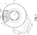
- a rotary connector device 1 comprises a stator 10 and a rotator 20.
- the stator 10 is configured to be mounted in a vehicle body.
- the rotator 20 is provided rotatably about a rotation axis A1 relative to the stator 10.
- the rotator 20 is configured to be fixed to a steering wheel.
- the rotary connector device 1 comprises a first connector 30 and a second connector 40.
- the first connector 30 is provided on the stator 10.
- the second connector 40 is provided on the rotator 20.
- the first connector 30 is configured with a vehicle body side connector detachably installed on the first connector 30.
- the first connector 30 includes a first connector housing portion 31 into which the vehicle body side connector is inserted.
- the vehicle body side connector is electrically connected to an electric circuit such as a control device.
- the second connector 40 is configured with a steering side connector detachably installed on the second connector 40.
- the second connector 40 includes a second connector housing portion 41 into which the steering side connector is inserted.
- the steering side connector is electrically connected to electric circuits such as switches for the steering wheel and an airbag device.
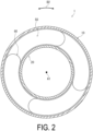
- the stator 10 and the rotator 20 define a cable housing space 50 between the stator 10 and the rotator 20, the cable housing space 50 provided surrounding the rotation axis A1.
- the cable housing space 50 is annular and extends in a circumferential direction D2 relative to the rotation axis A1.
- the rotary connector device 1 comprises an electrical cable 60.
- the electrical cable 60 electrically connects the first connector 30 to the second connector 40.
- the electrical cable 60 is housed in the cable housing space 50.
- the electrical cable 60 is flexible and has a flat shape.
- the electrical cable 60 may also be referred to as a flexible flat cable.
- the rotary connector device 1 comprises a lead block 70.
- the rotary connector device 1 comprises a plurality of the lead blocks 70.
- Lead blocks 70A and 70B of the plurality of lead blocks 70 are attached to the stator 10.
- the lead blocks 70A and 70B are disposed in the first connector housing portion 31.
- the lead blocks 70C and 70D of the plurality of lead blocks 70 are attached to the rotator 20.
- the lead blocks 70C and 70D are disposed in the second connector housing portion 41.
- the first connector 30 includes lead blocks 70A and 70B.
- the second connector 40 includes lead blocks 70C and 70D.
- the total number of the lead blocks 70 is not limited to the present embodiment.
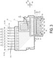
- the lead block 70 comprises a lead block body 71 and a plurality of busbars 72.
- the lead block body 71 includes an electrical insulating material.
- the plurality of busbars 72 are each partially embedded in the lead block body 71 and include an electrically conductive material.
- the electrical insulating material includes, for example, a resin material.
- the electrically conductive material includes a metal material such as copper, for example.
- the plurality of busbars 72 are electrically isolated from one another by the lead block body 71.
- the plurality of busbars 72 are respectively electrically connected to a plurality of wires included in the electrical cable 60 (see FIG. 2 ).
- the plurality of busbars 72 include a plurality of exposed portions 73 exposed from the lead block body 71 and corresponding to the respective plurality of busbars 72.
- the busbar 72 includes the exposed portion 73.
- the plurality of exposed portions 73 each extend in a longitudinal direction D4 and are spaced apart from one another in an arrangement direction D5 orthogonal to the longitudinal direction D4.
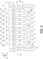
- the plurality of exposed portions 73 include at least one first exposed portion 74.
- the plurality of exposed portions 73 include a plurality of the first exposed portions 74.
- the total number of the first exposed portions 74 is not limited to the present embodiment.
- the plurality of exposed portions 73 include a second exposed portion 75.
- the plurality of exposed portions 73 include a third exposed portion 76.
- At least one of the first exposed portions 74 is disposed between the second exposed portion 75 and third exposed portion 76 in the arrangement direction D5.
- the plurality of first exposed portions 74 are disposed between the second exposed portion 75 and the third exposed portion 76 in the arrangement direction D5.
- the plurality of first exposed portions 74, the second exposed portion 75, and the third exposed portion 76 are spaced apart from one another in the arrangement direction D5.
- the plurality of busbars 72 include at least one first busbar 77 that includes the at least one first exposed portion 74.
- the at least one first busbar 77 includes a first end portion 77A and a first additional end portion 77B.
- the plurality of busbars 72 includes a plurality of the first busbars 77 including the plurality of first exposed portions 74.
- the plurality of busbars 72 each include the first end portion 77A and the first additional end portion 77B.
- the total number of the first busbars 77 is not limited to the present embodiment.
- the plurality of busbars 72 include a second busbar 78 that includes the second exposed portion 75.
- the plurality of busbars 72 include a third busbar 79 that includes the third exposed portion 76.
- the second busbar 78 includes a second end portion 78A and a second additional end portion 78B.
- the third busbar 79 includes a third end portion 79A and a third additional end portion 79B. At least one of the second busbar 78A and the third busbar 79 may be omitted from the plurality of busbars 72.
- the first end portion 77A is exposed from the lead block body 71.
- the first busbar 77 includes a first pin terminal 77C that is exposed from the lead block body 71.
- the first pin terminal 77C protrudes from the lead block body 71 in the longitudinal direction D4.
- the first pin terminal 77C includes the first end portion 77A.
- the first end portion 77A is disposed further on the outer side than a contour 71A of the lead block body 71.
- the first additional end portion 77B is disposed further on the inner side than the contour of the lead block body 71.
- the first additional end portion 77B is at least partially embedded in the lead block body 71.
- the first additional end portion 77B is partially embedded in the lead block body 71, but a portion of the surface of the first additional end portion 77B is exposed from the lead block body 71.
- the entirety of first additional end portion 77B may be embedded in the lead block body 71.
- the at least one first exposed portion 74 includes a first surface 80 and a first additional surface 81.
- the first additional surface 81 is disposed on the reverse side of the first surface 80 in the arrangement direction D5.
- Each of the plurality of first exposed portions 74 includes the first surface 80 and the first additional surface 81.
- the second exposed portion 75 includes a second surface 83 and a second additional surface 84.
- the second surface 83 faces toward the at least one first exposed portions 74 in the arrangement direction D5.
- the second additional surface 84 is disposed on the reverse side of the second surface 83 in the arrangement direction D5.
- the third exposed portion 76 includes a third surface 85 and a third additional surface 86.
- the third surface 85 faces toward the at least one first exposed portion 74 in the arrangement direction D5.
- the third additional surface 86 is disposed on the reverse side of the third surface 85 in the arrangement direction D5.
- One of the plurality of busbars 72 includes a first protruding portion 87 protruding from the second additional surface 84 of the second exposed portion 75 in the arrangement direction D5.
- the second busbar 78 includes the first protruding portion 87.
- the first protruding portion 87 is at least partially embedded in the lead block body 71. In the present embodiment, the first protruding portion 87 is partially embedded in the lead block body 71. However, the entirety of first protruding portion 87 may be embedded in the lead block body 71. Additionally, the first protruding portion 87 may be omitted from the plurality of busbars 72.
- One of the plurality of busbars 72 includes a second protruding portion 88 protruding from the third additional surface 86 of the third exposed portion 76 in the arrangement direction D5.
- the third busbar 79 includes the second protruding portion 88.
- the second protruding portion 88 is at least partially embedded in the lead block body 71.
- the second protruding portion 88 is partially embedded in the lead block body 71.
- the entirety of second protruding portion 88 may be embedded in the lead block body 71.
- the second protruding portion 88 may be omitted from the plurality of busbars 72.
- the lead block body 71 includes an opening 71B.
- the plurality of exposed portions 73 are at least partially disposed within the opening 71B as viewed in the orthogonal direction D6.
- the plurality of first exposed portions 74, the second exposed portion 75, and the third exposed portion 76 are disposed at least partially within the opening 71B as viewed in the orthogonal direction D6.
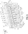
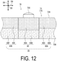
- the first surface 80 includes a first cut surface 90 having an area smaller than an area of the first surface 80.
- the first cut surface 90 is disposed within the opening 71B.
- a length L11 of the first cut surface 90 in the longitudinal direction D4 is shorter than a length L12 of the first surface 80 in the longitudinal direction D4.
- the first surface 80 includes a first adjacent surface 80A adjacent to the first cut surface 90.
- the first surface 80 includes a first adjacent surface 80B adjacent to the first cut surface 90.
- the appearance of the first cut surface 90 differs from the appearance of the first adjacent surface 80A.
- the appearance of the first cut surface 90 differs from the appearance of the first adjacent surface 80B.
- the appearance of the first adjacent surface 80A is the same as the appearance of the first adjacent surface 80B.
- the first cut surface 90 is a surface formed when a connector bar 104 (see FIGS. 9 to 11 ) is cut off from the plurality of first exposed portions 74 during manufacture of the lead block 70.
- the first adjacent surfaces 80A and 80B are surfaces formed by, for example, press machining (e.g., shearing), while the first cut surface 90 is a surface formed in a step different from and later than a step for forming the first adjacent surfaces 80A and 80B.
- the first cut surface 90 is, for example, a surface formed by press machining (e.g., shearing) similarly to the first adjacent surfaces 80A and 80B.
- the first adjacent surface 80A includes a shear surface 80C and a fracture surface 80D.
- the fracture surface 80D is adjacent to the shear surface 80C in the orthogonal direction D6.
- the shear surface 80C is a surface formed during shearing by shearing a material using a punch and a die, and includes a plurality of streaks extending in one direction (e.g., the orthogonal direction D6).
- the fracture surface 80D is a surface formed during shearing by fracturing of the material after shearing of a portion of the material using the punch and die, and includes fine recesses and protruding portions.
- the appearance of the shear surface 80C differs from the appearance of the fracture surface 80D.
- the first adjacent surface 80B includes a shear surface 80E and a fracture surface 80F.
- the fracture surface 80F is adjacent to the shear surface 80E in the orthogonal direction D6.
- the shear surface 80E is a surface formed during shearing by shearing of the material using the punch and die, and includes a plurality of streaks extending in one direction (e.g., the orthogonal direction D6).
- the fracture surface 80F is a surface formed during shearing by fracturing of the material after shearing of a portion of the material using the punch and die, and includes fine recesses and protruding portions.
- the appearance of the shear surface 80E differs from the appearance of the fracture surface 80F.
- the first cut surface 90 includes a first shear surface 90A and a first fracture surface 90B.
- the first fracture surface 90B is adjacent to the first shear surface 90A in the orthogonal direction D6.
- the first shear surface 90A is a surface formed during shearing by shearing of the material using the punch and die, and includes a plurality of streaks extending in one direction (e.g., the orthogonal direction D6).
- the first fracture surface 90B is a surface formed during shearing by fracturing of the material after shearing of a portion of the material using the punch and die, and includes fine recesses and protruding portions.
- the appearance of the first shear surface 90A differs from the appearance of the first fracture surface 90B.
- the length of the first shear surface 90A in the orthogonal direction D6 differs from the length of the shear surfaces 80C and 80E in the orthogonal direction D6.
- the length of the first fracture surface 90B in the orthogonal direction D6 differs from the length of the fracture surfaces 80D and 80F in the orthogonal direction D6.
- the appearance of the first cut surface 90 differs from the appearance of the first adjacent surfaces 80A and 80B.
- the first cut surface 90 may be a surface subjected to surface finish after the connector bar 104 is cut off from the plurality of first exposed portions 74.
- the first adjacent surfaces 80A and 80B may be a surface subjected to surface finish.
- the first shear surface 90A and the first fracture surface 90B are at least partially replaced with finished surfaces.
- the shear surface 80C and the fracture surface 80D are at least partially replaced with finished surfaces.
- the shear surface 80E and the fracture surface 80F are at least partially replaced with finished surfaces. Accordingly, the appearance of the first cut surface 90 may be the same as the appearance of the first adjacent surfaces 80A and 80B.
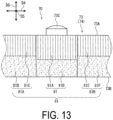
- the first additional surface 81 includes a first additional cut surface 91 having an area smaller than an area of the first additional surface 81.
- the first additional cut surface 91 is disposed within the opening 71B.
- a length L13 of the first additional cut surface 91 in the longitudinal direction D4 is shorter than a length L14 of the first additional surface 81 in the longitudinal direction D4.
- the first additional surface 81 includes a first additional adjacent surface 81A adjacent to the first additional cut surface 91.
- the first additional surface 81 includes a first additional adjacent surface 81B adjacent to the first additional cut surface 91.
- the appearance of the first additional cut surface 91 differs from the appearance of the first additional adjacent surface 81A.
- the appearance of the first additional cut surface 91 differs from the appearance of the first additional adjacent surface 81B.
- the appearance of the first additional adjacent surface 81A is the same as the appearance of the first additional adjacent surface 81B.
- the first additional cut surface 91 is disposed on the reverse side of the first cut surface 90 (see FIG. 5 ) in the arrangement direction D5.
- the first additional cut surface 91 is disposed at the same position as that of the first cut surface 90 in the longitudinal direction D4 (see FIG. 5 ).
- the first additional cut surface 91 need not be located on the reverse side of the first cut surface 90 (see FIG. 5 ) in the arrangement direction D5.
- the first additional cut surface 91 may be offset from the first cut surface 90 (see FIG. 5 ) in the longitudinal direction D4.
- the first additional cut surface 91 is a surface formed when the connector bar 104 (see FIGS. 9 to 11 ) is cut off from the plurality of first exposed portions 74 during manufacture of the lead block 70.
- the first additional adjacent surfaces 81A and 81B are surfaces formed by, for example, press machining (e.g., shearing), whereas the first additional cut surface 91 is a surface formed in a step different from and later than a step for forming the first additional adjacent surfaces 81A and 81B.
- the first additional cut surface 91 is, for example, a surface formed by press machining (e.g., shearing) similarly to the first additional adjacent surfaces 81A and 81B.
- the first additional adjacent surface 81A includes an additional shear surface 81C and an additional fracture surface 81D.
- the additional fracture surface 81D is adjacent to the additional shear surface 81C in the orthogonal direction D6.
- the additional shear surface 81C is a surface formed during shearing by shearing of the material using the punch and die, and includes a plurality of streaks extending in one direction (e.g., the orthogonal direction D6).
- the additional fracture surface 81D is a surface formed during shearing by fracturing of the material after shearing of a portion of the material using the punch and die, and includes fine recesses and protruding portions.
- the appearance of the additional shear surface 81C differs from the appearance of the additional fracture surface 81D.
- the first additional adjacent surface 81B includes an additional shear surface 81E and an additional fracture surface 81F.
- the additional fracture surface 81F is adjacent to the additional shear surface 81E in the orthogonal direction D6.
- the additional shear surface 81E is a surface formed during shearing by shearing of the material using the punch and die, and includes a plurality of streaks extending in one direction (e.g., the orthogonal direction D6).
- the additional fracture surface 81F is a surface formed during shearing by fracturing of the material after shearing of a portion of the material using the punch and die, and includes fine recesses and protruding portions.
- the appearance of the additional shear surface 81E differs from the appearance of the additional fracture surface 81F.
- the first additional cut surface 91 includes a first additional shear surface 91A and a first additional fracture surface 91B.
- the first additional fracture surface 91B is adjacent to the first additional shear surface 91A in the orthogonal direction D6.
- the first additional shear surface 91A is a surface formed during shearing by shearing of the material using the punch and die, and includes a plurality of streaks extending in one direction (e.g., the orthogonal direction D6).
- the first additional fracture surface 91B is a surface formed during shearing by fracturing of the material after shearing of a portion of the material using the punch and die, and includes fine recesses and protruding portions.
- the appearance of the first additional shear surface 91A differs from the appearance of the first additional fracture surface 91B.
- the length of the first additional shear surface 91A in the orthogonal direction D6 differs from the length of the additional shear surfaces 81C and 81E in the orthogonal direction D6.
- the length of the first additional fracture surface 91B in the orthogonal direction D6 differs from the length of the additional fracture surfaces 81D and 81F in the orthogonal direction D6.
- the appearance of the first additional cut surface 91 differs from the appearance of the first additional adjacent surfaces 81A and 81B.
- the first additional cut surface 91 may be a surface subjected to surface finish after the connector bar 104 is cut off from the plurality of first exposed portions 74.
- the first additional adjacent surfaces 81A and 81B may be surfaces subjected to surface finish.
- the first additional shear surface 91A and the first additional fracture surface 91B are at least partially replaced with finished surfaces.
- the additional shear surface 81C and the additional fracture surface 81D are at least partially replaced with finished surfaces.
- the additional shear surface 81E and the additional fracture surface 81F are at least partially replaced with finished surfaces. Accordingly, the appearance of the first additional cut surface 91 may be the same as the appearance of the first additional adjacent surfaces 81A and 81B.
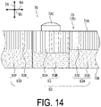
- the second surface 83 includes a second cut surface 93 having an area smaller than an area of the second surface 83.
- the second cut surface 93 is disposed within the opening 71B.
- a length L21 of the second cut surface 93 in the longitudinal direction D4 is shorter than a length L22 of the second surface 83 in the longitudinal direction D4.
- the second surface 83 includes second adjacent surfaces 83A and 83B adjacent to the second cut surface 93.
- the appearance of the second cut surface 93 differs from the appearance of each of the second adjacent surfaces 83A and 83B.
- the appearance of the second adjacent surface 83A is the same as the appearance of the second adjacent surface 83B.
- the second cut surface 93 is a surface formed when the connector bar 104 (see FIGS. 9 to 11 ) is cut off from the plurality of first exposed portions 74 during manufacture of the lead block 70.
- the second adjacent surfaces 83A and 83B are surfaces formed by, for example, press machining (e.g., shearing), while the second cut surface 93 is a surface formed in a step different from and later than a step for forming the second adjacent surfaces 83A and 83B.
- the second cut surface 93 is, for example, a surface formed by press machining (e.g., shearing) similarly to the second adjacent surfaces 83A and 83B.
- the second adjacent surface 83A includes a shear surface 83C and a fracture surface 83D.
- the fracture surface 83D is adjacent to the shear surface 83C in the orthogonal direction D6.
- the shear surface 83C is a surface formed during shearing by shearing of the material using the punch and die, and includes a plurality of streaks extending in one direction (e.g., the orthogonal direction D6).
- the fracture surface 83D is a surface formed during shearing by fracturing of the material after shearing of a portion of the material using the punch and die, and includes fine recesses and protruding portions.
- the appearance of the shear surface 83C differs from the appearance of the fracture surface 83D.
- the second adjacent surface 83B includes a shear surface 83E and a fracture surface 83F.
- the fracture surface 83F is adjacent to the shear surface 83E in the orthogonal direction D6.
- the shear surface 83E is a surface formed during shearing by shearing of the material using the punch and die, and includes a plurality of streaks extending in one direction (e.g., the orthogonal direction D6).
- the fracture surface 83F is a surface formed during shearing by fracturing of the material after shearing of a portion of the material using the punch and die, and includes fine recesses and protruding portions.
- the appearance of the shear surface 83E differs from the appearance of the fracture surface 83F.
- the second cut surface 93 includes a second shear surface 93A and a second fracture surface 93B.
- the second fracture surface 93B is adjacent to the second shear surface 93A in the orthogonal direction D6.
- the second shear surface 93A is a surface formed during shearing by shearing of the material using the punch and die, and includes a plurality of streaks extending in one direction (e.g., the orthogonal direction D6).
- the second fracture surface 93B is a surface formed during shearing by fracturing of the material after shearing of a portion of the material using the punch and die, and includes fine recesses and protruding portions.
- the appearance of the second shear surface 93A differs from the appearance of the second fracture surface 93B.
- the length of the second shear surface 93A in the orthogonal direction D6 differs from the length of the shear surfaces 83C and 83E in the orthogonal direction D6.
- the length of the second fracture surface 93B in the orthogonal direction D6 differs from the length of the fracture surfaces 83D and 83F in the orthogonal direction D6.
- the appearance of the second cut surface 93 differs from the appearance of the second adjacent surfaces 83A and 83B.
- the second cut surface 93 may be a surface subjected to surface finish after the connector bar 104 is cut off from the plurality of first exposed portions 74.
- the second adjacent surfaces 83A and 80B may be surfaces subjected to surface finish.
- the second shear surface 93A and the second fracture surface 93B are at least partially replaced with finished surfaces.
- the shear surface 83C and the fracture surface 83D are at least partially replaced with finished surfaces.
- the shear surface 83E and the fracture surface 83F are at least partially replaced with finished surfaces. Accordingly, the appearance of the second cut surface 93 may be the same as the appearance of the second adjacent surfaces 83Aand 83B.
- the third surface 85 includes a third cut surface 95 having an area smaller than an area of the third surface 85.
- the third cut surface 95 is disposed within the opening 71B.
- a length L31 of the third cut surface 95 in the longitudinal direction D4 is shorter than a length L32 of the third surface 85 in the longitudinal direction D4.
- the third surface 85 includes third adjacent surfaces 85A and 85B adjacent to the third cut surface 95.
- the appearance of the third cut surface 95 differs from the appearance of each of the third adjacent surfaces 85A and 85B.
- the appearance of the third adjacent surface 85A is the same as the appearance of the third adjacent surface 85B.
- the third cut surface 95 is a surface formed when the connector bar 104 (see FIGS. 9 to 11 ) is cut off from the plurality of first exposed portions 74 during manufacture of the lead block 70.
- the third adjacent surfaces 85A and 85B are surfaces formed by, for example, press machining (e.g., shearing), while the third cut surface 95 is a surface formed in a step different from and later than a step for forming the third adjacent surfaces 85A and 85B.
- the third cut surface 95 is, for example, a surface formed by press machining (e.g., shearing) similarly to the third adjacent surfaces 85A and 85B.
- the third adjacent surface 85A includes a shear surface 85C and a fracture surface 85D.
- the fracture surface 85D is adjacent to the shear surface 85C in the orthogonal direction D6.
- the shear surface 85C is a surface formed during shearing by shearing of the material using the punch and die, and includes a plurality of streaks extending in one direction (e.g., the orthogonal direction D6).
- the fracture surface 85D is a surface formed during shearing by fracturing of the material after shearing of a portion of the material using the punch and die, and includes fine recesses and protruding portions.
- the appearance of the shear surface 85C differs from the appearance of the fracture surface 85D.
- the third adjacent surface 85B includes a shear surface 85E and a fracture surface 85F.
- the fracture surface 85F is adjacent to the shear surface 85E in the orthogonal direction D6.
- the shear surface 85E is a surface formed during shearing by shearing of the material using the punch and die, and includes a plurality of streaks extending in one direction (e.g., the orthogonal direction D6).
- the fracture surface 85F is a surface formed during shearing by fracturing of the material after shearing of a portion of the material using the punch and die, and includes fine recesses and protruding portions.
- the appearance of the shear surface 85E differs from the appearance of the fracture surface 85F.
- the third cut surface 95 includes a third shear surface 95A and a third fracture surface 95B.
- the third fracture surface 95B is adjacent to the third shear surface 95A in the orthogonal direction D6.
- the third shear surface 95A is a surface formed during shearing by shearing of the material using the punch and die, and includes a plurality of streaks extending in one direction (e.g., the orthogonal direction D6).
- the third fracture surface 95B is a surface formed during shearing by fracturing of the material after shearing of a portion of the material using the punch and die, and includes fine recesses and protruding portions.
- the appearance of the third shear surface 95A differs from the appearance of the third fracture surface 95B.
- the length of the third shear surface 95A in the orthogonal direction D6 differs from the length of the shear surfaces 85C and 85E in the orthogonal direction D6.
- the length of the third fracture surface 95B in the orthogonal direction D6 differs from the length of the fracture surfaces 85D and 85F in the orthogonal direction D6.
- the appearance of the third cut surface 95 differs from the appearance of the third adjacent surfaces 85A and 85B.
- the third cut surface 95 may be a surface subjected to surface finish after the connector bar 104 is cut off from the plurality of first exposed portions 74.
- the third adjacent surfaces 85A and 80B may be surfaces subjected to surface finish.
- the third shear surface 95A and the third fracture surface 95B are at least partially replaced with finished surfaces.
- the shear surface 85C and the fracture surface 85D are at least partially replaced with finished surfaces.
- the shear surface 85E and the fracture surface 85F are at least partially replaced with finished surfaces. Accordingly, the appearance of the third cut surface 95 may be the same as the appearance of the third adjacent surfaces 85A and 85B.
- the first exposed portion 74 is disposed between the first end portion 77A and the first additional end portion 77B.
- the first cut surface 90 and the first additional cut surface 91 are disposed between the first end portion 77A and the first additional end portion 77B.
- the second cut surface 93 is disposed between the second end portion 78A and the second additional end portion 78B.
- the third cut surface 95 is disposed between the third end portion 79A and the third additional end portion 79B.
- the first protruding portion 87 includes a second additional cut surface 97.
- the second additional cut surface 97 is an end portion surface of the first protruding portion 87 and is exposed from the lead block body 71.
- the second additional cut surface 97 is a surface formed when the connector bar 104 (see FIGS. 9 to 11 ) is cut off from the first protruding portion 87 during manufacture of the lead block 70.
- the second protruding portion 88 includes a third additional cut surface 98.
- the third additional cut surface 98 is an end portion surface of the second protruding portion 88 and is exposed from the lead block body 71.
- the third additional cut surface 98 is a surface formed when the connector bar 104 (see FIGS. 9 to 11 ) is cut off from the second protruding portion 88 during manufacture of the lead block 70.
- the plurality of exposed portions 73 respectively include a plurality of cable mounting surfaces 73A.
- the cable mounting surface 73A is disposed facing in the orthogonal direction D6.
- the plurality of cable mounting surfaces 73A lie opposite to the electrical cable 60 (see FIG. 2 ) connected to the plurality of busbars 72.
- the plurality of exposed portions 73 respectively include a plurality of back surfaces 73B.
- the back surface 73B is disposed on the reverse side of the cable mounting surface 73A in the orthogonal direction D6.
- the back surface 73B is disposed facing in the orthogonal direction D6.
- the plurality of exposed portions 73 respectively include a plurality of projections 73C.
- the projection 73C protrudes from the cable mounting surface 73A in the orthogonal direction D6.
- the plurality of projections 73C are respectively electrically connected to a plurality of wires included in the electrical cable 60 (see FIG. 2 ).
- the plurality of projections 73C are connected by a connection method such as ultrasonic bonding or resistance welding with the plurality of wires included in the electrical cable 60 (see FIG. 2 ).
- the plurality of exposed portions 73 respectively include a plurality of recesses 73D.
- the recess 73D is disposed in the back surface 73B of each of the plurality of exposed portions 73.
- the recess 73D is disposed on the reverse side of the projection 73C in the orthogonal direction D6.
- the projection 73C and the recess 73D are formed by, for example, press machining. At least one of the projection 73C and the recess 73D may be omitted from the exposed portion 73.
- a method of manufacturing the lead block 70 will be described with reference to FIGS. 8 to 11 .
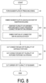
- the method of manufacturing the lead block 70 comprises the press machining step S1 including forming, by press machining, a busbar plate 102 from a plate 100 including an electrically conductive material.
- the busbar plate 102 includes the plurality of busbars 72, the connector bar 104 connecting the plurality of exposed portions 73 of the plurality of busbars 72 together, and a carrier 106 connecting the plurality of busbars 72 together.
- the plurality of first end portions 77A, the second end portion 78A, and the third end portion 79A are connected to the carrier 106.
- the method of manufacturing the lead block 70 comprises the molding step S2 including embedding, in the lead block body 71 by insertion molding, the busbar plate 102 including the plurality of busbars 72 and the connector bar 104 connecting the plurality of exposed portions 73 of the plurality of busbars 72 together so that the plurality of exposed portions 73 is exposed from the lead block body 71.
- the molding step S2 includes the step S21 of embedding the busbar plate 102 in the lead block body 71 by the insertion molding so that the plurality of exposed portions 73 and at least a portion of the connector bar 104 are disposed within the opening 71B of the lead block body 71.
- the molding step S2 includes the step S22 of embedding the busbar plate 102 in the lead block body 71 by the insertion molding so that a portion of the connector bar 104 is embedded in the lead block body 71.
- the steps S21 and S22 are typically performed by a single insertion molding operation, but may be performed by separate insertion molding operations. Additionally, one of the steps S21 and S22 may be omitted from the molding step S2.
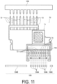
- the method of manufacturing the lead block 70 comprises the cutting step S3 including cutting the connector bar 104 off from the plurality of exposed portions 73.
- the cutting step S3 includes the step S31 of cutting the connector bar 104 off from the plurality of exposed portions 73 via the opening 71B in the lead block body 71.
- the connector bar 104 is cut off from the plurality of exposed portions 73 by press machining.
- the connector bar 104 includes a plurality of first connecting portions 104A, a second connecting portion 104B, and a third connecting portion 104C.
- the plurality of first connecting portions 104A are cut off from the plurality of exposed portions 73, the plurality of first cut surfaces 90 (see FIG. 5 ), the plurality of first additional cut surfaces 91 (see FIG. 6 ), the second cut surface 93 (see FIG. 5 ), and the third cut surface 95 (see FIG. 6 ) are formed.
- the second connecting portion 104B is cut off from the first protruding portion 87, the second additional cut surface 97 (see FIG. 6 ) is formed.
- the third connecting portion 104C is cut off from the second protruding portion 88, the third additional cut surface 98 (see FIG. 5 ) is formed.
- the method of manufacturing the lead block 70 includes the carrier cutting step S4 including cutting the carrier 106 off from the plurality of busbars 72. For example, by press machining, the carrier 106 is cut off from the plurality of busbars 72. Thus, the lead block 70 is manufactured. Note that in a case where the busbar plate 102 does not include the carrier 106, the carrier cutting step S4 may be omitted. Also, the cutting step S3 and the carrier cutting step S4 may be performed simultaneously as a single step or may be performed at different timings as separate steps.
- the aspects of the lead block 70 according to the present embodiment are as follows.
- the length of the first shear surface 90A in the orthogonal direction D6 is shorter than the length of the shear surfaces 80C and 80D in the orthogonal direction D6.
- the length of the first shear surface 90A in the orthogonal direction D6 may be longer than the length of the shear surfaces 80C and 80D in the orthogonal direction D6.
- the length of the first shear surface 90A in the orthogonal direction D6 may be equal to the length of the shear surfaces 80C and 80E in the orthogonal direction D6.
- the dimensional relationship described above can be applied to the dimensional relationship between the first additional shear surface 91A and the additional shear surfaces 81C and 81E, and to the dimensional relationship between the second shear surface 93A and the shear surfaces 83C and 83E, and to the dimensional relationship between the third shear surface 95A and the shear surfaces 85C and 85E.
- the first shear surface 90A and the shear surfaces 80C and 80E are disposed closer to the cable mounting surface 73A than the first fracture surface 90B and the fracture surfaces 80D and 80F.
- the first fracture surface 90B may be disposed near the cable mounting surface 73A.
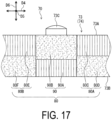
- the first cut surface 90 is disposed flush with the first adjacent surfaces 80A and 80B in the arrangement direction D5.
- the first cut surface 90 need not be disposed flush with the first adjacent surfaces 80A and 80B.
- the first additional cut surface 91 need not be disposed flush with the first additional adjacent surfaces 81A and 81B.
- the first cut surface 90 may be offset from the first adjacent surfaces 80A and 80B in the arrangement direction D5.
- the first additional cut surface 91 may be offset from the first additional adjacent surfaces 81A and 81B in the arrangement direction D5.
- This also applies to the positional relationship between the second cut surface 93 and the second adjacent surfaces 83A and 83B in the arrangement direction D5.
- the above-described relationship also applies to the positional relationship between the third cut surface 95 and the third adjacent surfaces 85A and 85B in the arrangement direction D5.
- the material is cut by press machining (specifically, shearing), but any other cutting method can be applied.
- a number such as “first” or “second” is merely a term for identifying a configuration, and does not have any other meaning (e.g., a particular order, or the like).
- first element does not imply that a “second element” exists
- second element does not imply that a "first element” exists.
- the expression "at least one of A and B” in the present disclosure encompasses, for example, all of (1) only A, (2) only B, and (3) both A and B.
- the expression “at least one of A, B, and C” encompasses, for example, all of (1) only A, (2) only B, (3) only C, (4) A and B, (5) B and C, (6) A and C, and (7) all of A, B, and C.
- the expression “at least one of A and B" is not interpreted as "at least one of A and at least one of B".
Landscapes
- Engineering & Computer Science (AREA)
- Manufacturing & Machinery (AREA)
- Mechanical Engineering (AREA)
- Connection Of Batteries Or Terminals (AREA)
- Connection Or Junction Boxes (AREA)
- Connector Housings Or Holding Contact Members (AREA)
- Connections Arranged To Contact A Plurality Of Conductors (AREA)
Abstract
Description
- The technology disclosed in the present application relates to a lead block and a rotary connector device.
-
Patent Documents 1 to 4 describe a rotary connector device having a lead block. -
- Patent Document 1:
JP 10-144371 A - Patent Document 2:
JP 2003-022879 A - Patent Document 3:
JP 2003-045598 A - Patent Document 4:
WO 2018/047581 - In consideration of the manufacturing costs of the rotary connector device, the manufacturing costs of lead blocks are preferably reduced.
- An object of the technology disclosed herein is to reduce the manufacturing costs of the lead blocks.
- A lead block according to a first aspect comprises a lead block body including an electrical insulating material and a plurality of busbars each partially embedded in the lead block body and including an electrically conductive material. The plurality of busbars include a plurality of exposed portions exposed from the lead block body and respectively corresponding to the plurality of busbars. The plurality of exposed portions each extend in a longitudinal direction and are disposed spaced apart from one another in an arrangement direction orthogonal to the longitudinal direction. The plurality of exposed portions include at least one first exposed portion. The at least one first exposed portion includes a first surface and a first additional surface disposed on a reverse side of the first surface in the arrangement direction. The first surface includes a first cut surface having an area smaller than an area of the first surface. The first additional surface includes a first additional cut surface having an area smaller than an area of the first additional surface.
- With the lead block according to the first aspect, the first cut surface having the area smaller than the area of the first surface is disposed on the first surface, and the first additional cut surface having the area smaller than the area of the first additional surface is disposed on the first additional surface, and thus, during manufacture, discarded materials cut off from the plurality of busbars can be reduced. This enables a reduction in the manufacturing costs of the lead block.
- In accordance with a lead block according to a second aspect, in the lead block according to the first aspect, the first surface includes a first adjacent surface adjacent to the first cut surface. The first additional surface includes a first additional adjacent surface adjacent to the first additional cut surface. Appearance of the first cut surface differs from appearance of the first adjacent surface. Appearance of the first additional cut surface differs from appearance of the first additional adjacent surface.
- With the lead block according to the second aspect, the step of surface finishing for the first cut surface and the first additional cut surface can be omitted. This enables a further reduction in the manufacturing costs of the lead block compared to a configuration in which the surface finishing of the first cut surface and the first additional cut surface is performed.
- In accordance with a lead block according to a third aspect, in the lead block according to the second aspect, the first cut surface is offset from the first adjacent surface in the arrangement direction.
- In accordance with a lead block according to a fourth aspect, in the lead block according to the second or third aspect, the first additional cut surface is offset from the first additional adjacent surface in the arrangement direction.
- In accordance with a lead block according to a fifth aspect, in the lead block according to any one of the first to fourth aspects, the first additional cut surface is disposed on a reverse side of the first cut surface in the arrangement direction.
- With the lead block according to the fifth aspect, for example, when, during manufacture, a connector bar connecting a plurality of the exposed portions together are cut off from the plurality of exposed portions, deformation of the plurality of exposed portions can be suppressed.
- In accordance with a lead block according to a sixth aspect, in the lead block according to any one of the first to fifth aspects, a length of the first cut surface in the arrangement direction is shorter than a length of the first surface in the arrangement direction. A length of first additional cut surface in the arrangement direction is shorter than a length of the first additional surface in the arrangement direction.
- The lead block according to the sixth aspect enables a reduction in discarded materials cut off from the plurality of busbars compared to a configuration in which the length of the first cut surface is equal to the length of the first surface and/or the length of the first additional cut surface is equal to the length of the first additional surface. This enables a further reduction in the manufacturing costs of the lead block.
- In accordance with a lead block according to a seventh aspect, in the lead block according to any one of the first to sixth aspects, the plurality of exposed portions include a second exposed portion. The second exposed portion includes a second surface facing toward the at least one first exposed portion in the arrangement direction, and a second additional surface disposed on a reverse side of the second surface in the arrangement direction. The second surface includes a second cut surface having an area smaller than an area of the second surface.
- With the lead block according to the seventh aspect, the second cut surface having the area smaller than the area of the second surface is disposed on the second surface, and thus, during manufacture, the discarded materials cut off from the plurality of busbars can be reduced. This enables a further reduction in the manufacturing costs of the lead block.
- In accordance with a lead block according to an eighth aspect, in the lead block according to the seventh aspect, one of the plurality of busbars includes a first protruding portion protruding from the second additional surface of the second exposed portion in the arrangement direction. The first protruding portion is at least partially embedded in the lead block body.
- With the lead block according to the eighth aspect, the first protruding portion is at least partially embedded in the lead block body, and thus, the connection strength between the second exposed portion and the lead block body can be increased, with the manufacturing costs of the lead block reduced. During manufacture, in a case where the connector bar connecting the plurality of exposed portions includes the first protruding portion, a portion of the connector bar can be utilized to increase the connection strength, allowing facilitation of effective utilization of the material of the lead block, with the connection strength between the second exposed portion and the lead block body increased.
- In accordance with a lead block according to a ninth aspect, in the lead block according to the seventh or eighth aspect, the plurality of exposed portions include a third exposed portion. The third exposed portion includes a third surface facing toward the at least one first exposed portions in the arrangement direction and a third additional surface disposed on a reverse side of the third surface in the arrangement direction. The third surface includes a third cut surface having an area smaller than an area of the third surface.
- With the lead block according to the ninth aspect, the third cut surface having the area smaller than the area of the third surface is disposed on the third surface, and thus, during manufacture, the discarded materials cut off from the plurality of busbars can be reduced. This enables a further reduction in the manufacturing costs of the lead block.
- In accordance with a lead block according to a tenth aspect, in the lead block according to the ninth aspect, one of the plurality of busbars includes a second protruding portion protruding from the third additional surface of the third exposed portion in the arrangement direction. The second protruding portion is at least partially embedded in the lead block body.
- With the lead block according to the tenth aspect, the second protruding portion is at least partially embedded in the lead block body, and thus, the connection strength between the third exposed portion and the lead block body can be increased, with the manufacturing costs of the lead block reduced. In a case where the connector bar connecting the plurality of exposed portions at the time of manufacture includes the second protruding portion, a portion of the connector bar can be utilized to increase the connection strength, allowing facilitation of effective utilization of the material of the lead block, with the connection strength between the third exposed portion and the lead block body increased.
- In accordance with a lead block of an eleventh aspect, in the lead block according to any one of the first to tenth aspects, the plurality of busbars include at least one first busbar including at least one first exposed portion. The at least one first busbar includes a first end portion and a first additional end portion. In the at least one first busbar, the first cut surface and the first additional cut surface are disposed between the first end portion and the first additional end portion.
- With the lead block according to the eleventh aspect, the first cut surface and the first additional cut surface are provided on portions other than the first end portion and the first additional end portion, thus facilitating integral holding of the plurality of busbars with less materials during manufacture.
- In accordance with a lead block according to a twelfth aspect, in the lead block according to the eleventh aspect, the first end portion is exposed from the lead block body. As viewed in an orthogonal direction orthogonal to the longitudinal direction and the arrangement direction, the first additional end portion is disposed further on an inner side than a contour of the lead block body.
- The lead block according to the twelfth aspect allows suppression of contact of the first additional end portion with another member such as a cable compared to a configuration in which the first additional end portion is disposed on the contour of the lead block body or further on an outer side than the contour of the lead block body.
- In accordance with a lead block according to a thirteenth aspect, in the lead block according to the eleventh or twelfth aspect, the first additional end portion is at least partially embedded in the lead block body.
- The lead block according to the thirteenth aspect allows reliable suppression of the contact of the first additional end portion with another member such as a cable.
- In accordance with a lead block of a fourteenth aspect, in the lead block according to any one of the first to thirteenth aspects, the lead block body includes an opening. The first cut surface and the first additional cut surface are disposed within the opening.
- With the lead block according to the fourteenth aspect, during manufacture, the connector bar connecting the plurality of exposed portions can be cut off from a plurality of connecting portions via the opening.
- A rotary connector device according to a fifteenth aspects comprises a stator, a rotator provided rotatably about a rotation axis with respect to the stator, and the lead block according to any one of the first to fourteenth aspects.
- With the rotary connector device according to the fifteenth aspect, the manufacturing costs of the lead blocks can be reduced, enabling a reduction in the manufacturing costs of the rotary connector device.
- A method of manufacturing a lead block according to a sixteenth aspect comprises: a molding step including embedding, in a lead block body by insertion molding, a busbar plate including a plurality of busbars and a connector bar connecting a plurality of exposed portions of the plurality of busbars together so that the plurality of exposed portions is exposed from the lead block body; and a cutting step including cutting the connector bar off from the plurality of exposed portions.
- With the method of manufacturing a lead block according to the sixteenth aspect, discarded materials cut off from the plurality of busbars can be reduced. This enables a reduction in the manufacturing costs of the lead block.
- A method of manufacturing a lead block according to a seventeenth aspect corresponds to the method of manufacturing a lead block according to the sixteenth aspect, in which the molding step includes the step of embedding the busbar plate in the lead block body by insertion molding so that the plurality of exposed portions and at least a portion of the connector bar disposed within an opening of the lead block body.
- With the method of manufacturing a lead block according to the seventeenth aspect, a peripheral portion of the plurality of exposed portions can be held by the lead block body.
- In accordance with a method of manufacturing a lead block according to an eighteenth aspect, in the method of manufacturing a lead block according to the seventeenth aspect, the cutting step includes a step of cutting the connector bar off from the plurality of exposed portions via the opening in the lead block body.
- With the method of manufacturing a lead block according to the eighteenth aspect, the connector bar can be cut off from the plurality of exposed portions with the peripheral portion of the plurality of exposed portions held by the lead block body. This stabilizes the cutting operation.
- In accordance with a method of manufacturing a lead block according to a nineteenth aspect, in the method of manufacturing a lead block according to any one of the sixteenth to eighteenth aspects, the molding step includes a step of embedding the busbar plate in the lead block body by insertion molding, with a portion of the connector bar embedded in the lead block body.
- With the method of manufacturing a lead block according to the nineteenth aspect, the connection strength between the plurality of exposed portions and the lead block body can be increased.
- In accordance with a lead block according to a twentieth aspect, the method of manufacturing a lead block according to any one of the sixteenth to nineteenth aspects further comprises a press machining step including forming, by press machining, the busbar plate from a plate including an electrically conductive material.
- With the method of manufacturing a lead block according to the twentieth aspect, remaining portions cut off from the busbar plate by press machining can be reduced.
- The technology disclosed herein can reduce the manufacturing costs of the lead block.
-
-
FIG. 1 is a plan view of a rotary connector device according to the present embodiment. -
FIG. 2 is a cross-sectional view of the rotary connector device illustrated inFIG. 1 . -
FIG. 3 is a side view of a lead block of the rotary connector device illustrated inFIG. 1 . -
FIG. 4 is a partial side view of the lead block illustrated inFIG. 3 . -
FIG. 5 is a partial perspective view of the lead block illustrated inFIG. 3 . -
FIG. 6 is a partial perspective view of the lead block illustrated inFIG. 3 . -
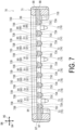
FIG. 7 is a cross-sectional view of the lead block taken along a line VII-VII ofFIG. 4 . -
FIG. 8 is a flowchart illustrating a method of manufacturing the lead block illustrated inFIG. 3 . -
FIG. 9 is a plan view illustrating the press machining step for the lead block illustrated inFIG. 3 . -
FIG. 10 is a plan view illustrating the molding step for the lead block illustrated inFIG. 3 . -
FIG. 11 is a plan view illustrating the cutting step and the step of carrier cutting for the lead block illustrated inFIG. 3 . -
FIG. 12 is a view illustrating a surface state of a first surface of the lead block illustrated inFIG. 3 . -
FIG. 13 is a diagram illustrating a surface state of a first additional surface of the lead block illustrated inFIG. 3 . -
FIG. 14 is a diagram illustrating a surface state of a second surface of the lead block illustrated inFIG. 3 . -
FIG. 15 is a diagram illustrating a surface state of a third surface of the lead block illustrated inFIG. 3 . -
FIG. 16 is a diagram illustrating a surface state of a first surface of a lead block according to a modified example. -
FIG. 17 is a diagram illustrating a surface state of a first surface of a lead block according to a modified example. -
FIG. 18 illustrates a positional relationship between a first cut surface and a first adjacent surface and a positional relationship between a first additional cut surface and a first additional adjacent surface, in a lead block according to a modified example. -
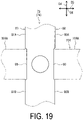
FIG. 19 illustrates a positional relationship between a first cut surface and a first adjacent surface and a positional relationship between a first additional cut surface and a first additional adjacent surface, in a lead block according to a modified example. - Hereinafter, embodiments will be described with reference to the drawings. In the drawings, the same reference signs denote corresponding or identical components.
- As illustrated in
FIG. 1 , arotary connector device 1 according to the present embodiment comprises astator 10 and arotator 20. Thestator 10 is configured to be mounted in a vehicle body. Therotator 20 is provided rotatably about a rotation axis A1 relative to thestator 10. Therotator 20 is configured to be fixed to a steering wheel. Therotary connector device 1 comprises afirst connector 30 and asecond connector 40. Thefirst connector 30 is provided on thestator 10. Thesecond connector 40 is provided on therotator 20. - The
first connector 30 is configured with a vehicle body side connector detachably installed on thefirst connector 30. Thefirst connector 30 includes a firstconnector housing portion 31 into which the vehicle body side connector is inserted. The vehicle body side connector is electrically connected to an electric circuit such as a control device. Thesecond connector 40 is configured with a steering side connector detachably installed on thesecond connector 40. Thesecond connector 40 includes a secondconnector housing portion 41 into which the steering side connector is inserted. The steering side connector is electrically connected to electric circuits such as switches for the steering wheel and an airbag device. - As illustrated in
FIG. 2 , thestator 10 and therotator 20 define acable housing space 50 between thestator 10 and therotator 20, thecable housing space 50 provided surrounding the rotation axis A1. For example, thecable housing space 50 is annular and extends in a circumferential direction D2 relative to the rotation axis A1. Therotary connector device 1 comprises anelectrical cable 60. Theelectrical cable 60 electrically connects thefirst connector 30 to thesecond connector 40. Theelectrical cable 60 is housed in thecable housing space 50. Theelectrical cable 60 is flexible and has a flat shape. Theelectrical cable 60 may also be referred to as a flexible flat cable. - As illustrated in
FIG. 1 , therotary connector device 1 comprises alead block 70. In the present embodiment, therotary connector device 1 comprises a plurality of the lead blocks 70. Lead blocks 70A and 70B of the plurality of lead blocks 70 are attached to thestator 10. The lead blocks 70A and 70B are disposed in the firstconnector housing portion 31. The lead blocks 70C and 70D of the plurality of lead blocks 70 are attached to therotator 20. The lead blocks 70C and 70D are disposed in the secondconnector housing portion 41. Thefirst connector 30 includeslead blocks second connector 40 includeslead blocks 70C and 70D. However, the total number of the lead blocks 70 is not limited to the present embodiment. - As illustrated in
FIG. 3 , thelead block 70 comprises alead block body 71 and a plurality ofbusbars 72. Thelead block body 71 includes an electrical insulating material. The plurality ofbusbars 72 are each partially embedded in thelead block body 71 and include an electrically conductive material. The electrical insulating material includes, for example, a resin material. The electrically conductive material includes a metal material such as copper, for example. The plurality ofbusbars 72 are electrically isolated from one another by thelead block body 71. The plurality ofbusbars 72 are respectively electrically connected to a plurality of wires included in the electrical cable 60 (seeFIG. 2 ). - The plurality of
busbars 72 include a plurality of exposedportions 73 exposed from thelead block body 71 and corresponding to the respective plurality ofbusbars 72. Thebusbar 72 includes the exposedportion 73. The plurality of exposedportions 73 each extend in a longitudinal direction D4 and are spaced apart from one another in an arrangement direction D5 orthogonal to the longitudinal direction D4. - The plurality of exposed
portions 73 include at least one first exposedportion 74. In the present embodiment, the plurality of exposedportions 73 include a plurality of the first exposedportions 74. However, the total number of the first exposedportions 74 is not limited to the present embodiment. - The plurality of exposed
portions 73 include a second exposedportion 75. The plurality of exposedportions 73 include a third exposedportion 76. At least one of the first exposedportions 74 is disposed between the second exposedportion 75 and third exposedportion 76 in the arrangement direction D5. The plurality of first exposedportions 74 are disposed between the second exposedportion 75 and the third exposedportion 76 in the arrangement direction D5. The plurality of first exposedportions 74, the second exposedportion 75, and the third exposedportion 76 are spaced apart from one another in the arrangement direction D5. - The plurality of
busbars 72 include at least onefirst busbar 77 that includes the at least one first exposedportion 74. The at least onefirst busbar 77 includes afirst end portion 77A and a firstadditional end portion 77B. In the present embodiment, the plurality ofbusbars 72 includes a plurality of thefirst busbars 77 including the plurality of first exposedportions 74. The plurality ofbusbars 72 each include thefirst end portion 77A and the firstadditional end portion 77B. However, the total number of thefirst busbars 77 is not limited to the present embodiment. - The plurality of
busbars 72 include asecond busbar 78 that includes the second exposedportion 75. The plurality ofbusbars 72 include athird busbar 79 that includes the third exposedportion 76. Thesecond busbar 78 includes asecond end portion 78A and a secondadditional end portion 78B. Thethird busbar 79 includes athird end portion 79A and a thirdadditional end portion 79B. At least one of thesecond busbar 78A and thethird busbar 79 may be omitted from the plurality ofbusbars 72. - The
first end portion 77A is exposed from thelead block body 71. Thefirst busbar 77 includes a first pin terminal 77C that is exposed from thelead block body 71. The first pin terminal 77C protrudes from thelead block body 71 in the longitudinal direction D4. The first pin terminal 77C includes thefirst end portion 77A. As viewed in an orthogonal direction D6 orthogonal to the longitudinal direction D4 and the arrangement direction D5, thefirst end portion 77A is disposed further on the outer side than acontour 71A of thelead block body 71. - On the other hand, as viewed in the orthogonal direction D6 orthogonal to the longitudinal direction D4 and the arrangement direction D5, the first
additional end portion 77B is disposed further on the inner side than the contour of thelead block body 71. The firstadditional end portion 77B is at least partially embedded in thelead block body 71. In the present embodiment, the firstadditional end portion 77B is partially embedded in thelead block body 71, but a portion of the surface of the firstadditional end portion 77B is exposed from thelead block body 71. However, the entirety of firstadditional end portion 77B may be embedded in thelead block body 71. - As illustrated in
FIG. 4 , the at least one first exposedportion 74 includes afirst surface 80 and a firstadditional surface 81. The firstadditional surface 81 is disposed on the reverse side of thefirst surface 80 in the arrangement direction D5. Each of the plurality of first exposedportions 74 includes thefirst surface 80 and the firstadditional surface 81. - The second exposed
portion 75 includes asecond surface 83 and a secondadditional surface 84. Thesecond surface 83 faces toward the at least one firstexposed portions 74 in the arrangement direction D5. The secondadditional surface 84 is disposed on the reverse side of thesecond surface 83 in the arrangement direction D5. - The third
exposed portion 76 includes athird surface 85 and a thirdadditional surface 86. Thethird surface 85 faces toward the at least one first exposedportion 74 in the arrangement direction D5. The thirdadditional surface 86 is disposed on the reverse side of thethird surface 85 in the arrangement direction D5. - One of the plurality of
busbars 72 includes a first protrudingportion 87 protruding from the secondadditional surface 84 of the second exposedportion 75 in the arrangement direction D5. Thesecond busbar 78 includes the first protrudingportion 87. The first protrudingportion 87 is at least partially embedded in thelead block body 71. In the present embodiment, the first protrudingportion 87 is partially embedded in thelead block body 71. However, the entirety of first protrudingportion 87 may be embedded in thelead block body 71. Additionally, the first protrudingportion 87 may be omitted from the plurality ofbusbars 72. - One of the plurality of
busbars 72 includes a second protrudingportion 88 protruding from the thirdadditional surface 86 of the third exposedportion 76 in the arrangement direction D5. Thethird busbar 79 includes the second protrudingportion 88. The second protrudingportion 88 is at least partially embedded in thelead block body 71. In the present embodiment, the second protrudingportion 88 is partially embedded in thelead block body 71. However, the entirety of second protrudingportion 88 may be embedded in thelead block body 71. Additionally, the second protrudingportion 88 may be omitted from the plurality ofbusbars 72. - The
lead block body 71 includes anopening 71B. The plurality of exposedportions 73 are at least partially disposed within theopening 71B as viewed in the orthogonal direction D6. The plurality of first exposedportions 74, the second exposedportion 75, and the third exposedportion 76 are disposed at least partially within theopening 71B as viewed in the orthogonal direction D6. - As illustrated in
FIG. 5 , thefirst surface 80 includes afirst cut surface 90 having an area smaller than an area of thefirst surface 80. Thefirst cut surface 90 is disposed within theopening 71B. A length L11 of thefirst cut surface 90 in the longitudinal direction D4 is shorter than a length L12 of thefirst surface 80 in the longitudinal direction D4. Thefirst surface 80 includes a firstadjacent surface 80A adjacent to thefirst cut surface 90. Thefirst surface 80 includes a firstadjacent surface 80B adjacent to thefirst cut surface 90. The appearance of thefirst cut surface 90 differs from the appearance of the firstadjacent surface 80A. The appearance of thefirst cut surface 90 differs from the appearance of the firstadjacent surface 80B. The appearance of the firstadjacent surface 80A is the same as the appearance of the firstadjacent surface 80B. - As described below, the
first cut surface 90 is a surface formed when a connector bar 104 (seeFIGS. 9 to 11 ) is cut off from the plurality of first exposedportions 74 during manufacture of thelead block 70. The firstadjacent surfaces first cut surface 90 is a surface formed in a step different from and later than a step for forming the firstadjacent surfaces first cut surface 90 is, for example, a surface formed by press machining (e.g., shearing) similarly to the firstadjacent surfaces - As illustrated in
FIG. 12 , the firstadjacent surface 80A includes ashear surface 80C and afracture surface 80D. Thefracture surface 80D is adjacent to theshear surface 80C in the orthogonal direction D6. Theshear surface 80C is a surface formed during shearing by shearing a material using a punch and a die, and includes a plurality of streaks extending in one direction (e.g., the orthogonal direction D6). Thefracture surface 80D is a surface formed during shearing by fracturing of the material after shearing of a portion of the material using the punch and die, and includes fine recesses and protruding portions. Thus, the appearance of theshear surface 80C differs from the appearance of thefracture surface 80D. - Similarly, the first
adjacent surface 80B includes ashear surface 80E and afracture surface 80F. Thefracture surface 80F is adjacent to theshear surface 80E in the orthogonal direction D6. Theshear surface 80E is a surface formed during shearing by shearing of the material using the punch and die, and includes a plurality of streaks extending in one direction (e.g., the orthogonal direction D6). Thefracture surface 80F is a surface formed during shearing by fracturing of the material after shearing of a portion of the material using the punch and die, and includes fine recesses and protruding portions. Thus, the appearance of theshear surface 80E differs from the appearance of thefracture surface 80F. - The
first cut surface 90 includes afirst shear surface 90A and afirst fracture surface 90B. Thefirst fracture surface 90B is adjacent to thefirst shear surface 90A in the orthogonal direction D6. Thefirst shear surface 90A is a surface formed during shearing by shearing of the material using the punch and die, and includes a plurality of streaks extending in one direction (e.g., the orthogonal direction D6). Thefirst fracture surface 90B is a surface formed during shearing by fracturing of the material after shearing of a portion of the material using the punch and die, and includes fine recesses and protruding portions. Thus, the appearance of thefirst shear surface 90A differs from the appearance of thefirst fracture surface 90B. - As illustrated in
FIG. 12 , the length of thefirst shear surface 90A in the orthogonal direction D6 differs from the length of the shear surfaces 80C and 80E in the orthogonal direction D6. The length of thefirst fracture surface 90B in the orthogonal direction D6 differs from the length of the fracture surfaces 80D and 80F in the orthogonal direction D6. Accordingly, the appearance of thefirst cut surface 90 differs from the appearance of the firstadjacent surfaces first cut surface 90 may be a surface subjected to surface finish after theconnector bar 104 is cut off from the plurality of first exposedportions 74. Similarly, the firstadjacent surfaces first cut surface 90 is subjected to surface finish, thefirst shear surface 90A and thefirst fracture surface 90B are at least partially replaced with finished surfaces. In a case where the firstadjacent surface 80A is subjected to surface finish, theshear surface 80C and thefracture surface 80D are at least partially replaced with finished surfaces. In a case where the firstadjacent surface 80B is subjected to surface finish, theshear surface 80E and thefracture surface 80F are at least partially replaced with finished surfaces. Accordingly, the appearance of thefirst cut surface 90 may be the same as the appearance of the firstadjacent surfaces - As illustrated in
FIG. 6 , the firstadditional surface 81 includes a firstadditional cut surface 91 having an area smaller than an area of the firstadditional surface 81. The firstadditional cut surface 91 is disposed within theopening 71B. A length L13 of the firstadditional cut surface 91 in the longitudinal direction D4 is shorter than a length L14 of the firstadditional surface 81 in the longitudinal direction D4. The firstadditional surface 81 includes a first additionaladjacent surface 81A adjacent to the firstadditional cut surface 91. The firstadditional surface 81 includes a first additionaladjacent surface 81B adjacent to the firstadditional cut surface 91. The appearance of the firstadditional cut surface 91 differs from the appearance of the first additionaladjacent surface 81A. The appearance of the firstadditional cut surface 91 differs from the appearance of the first additionaladjacent surface 81B. The appearance of the first additionaladjacent surface 81A is the same as the appearance of the first additionaladjacent surface 81B. - The first
additional cut surface 91 is disposed on the reverse side of the first cut surface 90 (seeFIG. 5 ) in the arrangement direction D5. The firstadditional cut surface 91 is disposed at the same position as that of thefirst cut surface 90 in the longitudinal direction D4 (seeFIG. 5 ). However, the firstadditional cut surface 91 need not be located on the reverse side of the first cut surface 90 (seeFIG. 5 ) in the arrangement direction D5. The firstadditional cut surface 91 may be offset from the first cut surface 90 (seeFIG. 5 ) in the longitudinal direction D4. - As described below, the first
additional cut surface 91 is a surface formed when the connector bar 104 (seeFIGS. 9 to 11 ) is cut off from the plurality of first exposedportions 74 during manufacture of thelead block 70. The first additionaladjacent surfaces additional cut surface 91 is a surface formed in a step different from and later than a step for forming the first additionaladjacent surfaces additional cut surface 91 is, for example, a surface formed by press machining (e.g., shearing) similarly to the first additionaladjacent surfaces - As illustrated in
FIG. 13 , the first additionaladjacent surface 81A includes anadditional shear surface 81C and anadditional fracture surface 81D. Theadditional fracture surface 81D is adjacent to theadditional shear surface 81C in the orthogonal direction D6. Theadditional shear surface 81C is a surface formed during shearing by shearing of the material using the punch and die, and includes a plurality of streaks extending in one direction (e.g., the orthogonal direction D6). Theadditional fracture surface 81D is a surface formed during shearing by fracturing of the material after shearing of a portion of the material using the punch and die, and includes fine recesses and protruding portions. Thus, the appearance of theadditional shear surface 81C differs from the appearance of theadditional fracture surface 81D. - Similarly, the first additional
adjacent surface 81B includes anadditional shear surface 81E and anadditional fracture surface 81F. Theadditional fracture surface 81F is adjacent to theadditional shear surface 81E in the orthogonal direction D6. Theadditional shear surface 81E is a surface formed during shearing by shearing of the material using the punch and die, and includes a plurality of streaks extending in one direction (e.g., the orthogonal direction D6). Theadditional fracture surface 81F is a surface formed during shearing by fracturing of the material after shearing of a portion of the material using the punch and die, and includes fine recesses and protruding portions. Thus, the appearance of theadditional shear surface 81E differs from the appearance of theadditional fracture surface 81F. - The first
additional cut surface 91 includes a firstadditional shear surface 91A and a firstadditional fracture surface 91B. The firstadditional fracture surface 91B is adjacent to the firstadditional shear surface 91A in the orthogonal direction D6. The firstadditional shear surface 91A is a surface formed during shearing by shearing of the material using the punch and die, and includes a plurality of streaks extending in one direction (e.g., the orthogonal direction D6). The firstadditional fracture surface 91B is a surface formed during shearing by fracturing of the material after shearing of a portion of the material using the punch and die, and includes fine recesses and protruding portions. Thus, the appearance of the firstadditional shear surface 91A differs from the appearance of the firstadditional fracture surface 91B. - As illustrated in
FIG. 13 , the length of the firstadditional shear surface 91A in the orthogonal direction D6 differs from the length of theadditional shear surfaces additional fracture surface 91B in the orthogonal direction D6 differs from the length of theadditional fracture surfaces additional cut surface 91 differs from the appearance of the first additionaladjacent surfaces additional cut surface 91 may be a surface subjected to surface finish after theconnector bar 104 is cut off from the plurality of first exposedportions 74. Similarly, the first additionaladjacent surfaces additional cut surface 91 is subjected to surface finish, the firstadditional shear surface 91A and the firstadditional fracture surface 91B are at least partially replaced with finished surfaces. In a case where the first additionaladjacent surface 81A is subjected to surface finish, theadditional shear surface 81C and theadditional fracture surface 81D are at least partially replaced with finished surfaces. In a case where the first additionaladjacent surface 81B is subjected to surface finish, theadditional shear surface 81E and theadditional fracture surface 81F are at least partially replaced with finished surfaces. Accordingly, the appearance of the firstadditional cut surface 91 may be the same as the appearance of the first additionaladjacent surfaces - As illustrated in
FIG. 5 , thesecond surface 83 includes asecond cut surface 93 having an area smaller than an area of thesecond surface 83. Thesecond cut surface 93 is disposed within theopening 71B. A length L21 of thesecond cut surface 93 in the longitudinal direction D4 is shorter than a length L22 of thesecond surface 83 in the longitudinal direction D4. Thesecond surface 83 includes secondadjacent surfaces second cut surface 93. The appearance of thesecond cut surface 93 differs from the appearance of each of the secondadjacent surfaces adjacent surface 83A is the same as the appearance of the secondadjacent surface 83B. - As described below, the
second cut surface 93 is a surface formed when the connector bar 104 (seeFIGS. 9 to 11 ) is cut off from the plurality of first exposedportions 74 during manufacture of thelead block 70. The secondadjacent surfaces second cut surface 93 is a surface formed in a step different from and later than a step for forming the secondadjacent surfaces second cut surface 93 is, for example, a surface formed by press machining (e.g., shearing) similarly to the secondadjacent surfaces - As illustrated in
FIG. 14 , the secondadjacent surface 83A includes ashear surface 83C and afracture surface 83D. Thefracture surface 83D is adjacent to theshear surface 83C in the orthogonal direction D6. Theshear surface 83C is a surface formed during shearing by shearing of the material using the punch and die, and includes a plurality of streaks extending in one direction (e.g., the orthogonal direction D6). Thefracture surface 83D is a surface formed during shearing by fracturing of the material after shearing of a portion of the material using the punch and die, and includes fine recesses and protruding portions. Thus, the appearance of theshear surface 83C differs from the appearance of thefracture surface 83D. - Similarly, the second
adjacent surface 83B includes ashear surface 83E and afracture surface 83F. Thefracture surface 83F is adjacent to theshear surface 83E in the orthogonal direction D6. Theshear surface 83E is a surface formed during shearing by shearing of the material using the punch and die, and includes a plurality of streaks extending in one direction (e.g., the orthogonal direction D6). Thefracture surface 83F is a surface formed during shearing by fracturing of the material after shearing of a portion of the material using the punch and die, and includes fine recesses and protruding portions. Thus, the appearance of theshear surface 83E differs from the appearance of thefracture surface 83F. - The
second cut surface 93 includes asecond shear surface 93A and asecond fracture surface 93B. Thesecond fracture surface 93B is adjacent to thesecond shear surface 93A in the orthogonal direction D6. Thesecond shear surface 93A is a surface formed during shearing by shearing of the material using the punch and die, and includes a plurality of streaks extending in one direction (e.g., the orthogonal direction D6). Thesecond fracture surface 93B is a surface formed during shearing by fracturing of the material after shearing of a portion of the material using the punch and die, and includes fine recesses and protruding portions. Thus, the appearance of thesecond shear surface 93A differs from the appearance of thesecond fracture surface 93B. - As illustrated in
FIG. 14 , the length of thesecond shear surface 93A in the orthogonal direction D6 differs from the length of the shear surfaces 83C and 83E in the orthogonal direction D6. The length of thesecond fracture surface 93B in the orthogonal direction D6 differs from the length of the fracture surfaces 83D and 83F in the orthogonal direction D6. Thus, the appearance of thesecond cut surface 93 differs from the appearance of the secondadjacent surfaces second cut surface 93 may be a surface subjected to surface finish after theconnector bar 104 is cut off from the plurality of first exposedportions 74. Similarly, the secondadjacent surfaces second cut surface 93 is subjected to surface finish, thesecond shear surface 93A and thesecond fracture surface 93B are at least partially replaced with finished surfaces. In a case where the secondadjacent surface 83A is subjected to surface finish, theshear surface 83C and thefracture surface 83D are at least partially replaced with finished surfaces. In a case where the secondadjacent surface 83B is subjected to surface finish, theshear surface 83E and thefracture surface 83F are at least partially replaced with finished surfaces. Accordingly, the appearance of thesecond cut surface 93 may be the same as the appearance of the secondadjacent surfaces 83Aand 83B. - As illustrated in
FIG. 6 , thethird surface 85 includes athird cut surface 95 having an area smaller than an area of thethird surface 85. Thethird cut surface 95 is disposed within theopening 71B. A length L31 of thethird cut surface 95 in the longitudinal direction D4 is shorter than a length L32 of thethird surface 85 in the longitudinal direction D4. Thethird surface 85 includes thirdadjacent surfaces third cut surface 95. The appearance of thethird cut surface 95 differs from the appearance of each of the thirdadjacent surfaces adjacent surface 85A is the same as the appearance of the thirdadjacent surface 85B. - As described below, the
third cut surface 95 is a surface formed when the connector bar 104 (seeFIGS. 9 to 11 ) is cut off from the plurality of first exposedportions 74 during manufacture of thelead block 70. The thirdadjacent surfaces third cut surface 95 is a surface formed in a step different from and later than a step for forming the thirdadjacent surfaces third cut surface 95 is, for example, a surface formed by press machining (e.g., shearing) similarly to the thirdadjacent surfaces - As illustrated in
FIG. 15 , the thirdadjacent surface 85A includes ashear surface 85C and afracture surface 85D. Thefracture surface 85D is adjacent to theshear surface 85C in the orthogonal direction D6. Theshear surface 85C is a surface formed during shearing by shearing of the material using the punch and die, and includes a plurality of streaks extending in one direction (e.g., the orthogonal direction D6). Thefracture surface 85D is a surface formed during shearing by fracturing of the material after shearing of a portion of the material using the punch and die, and includes fine recesses and protruding portions. Thus, the appearance of theshear surface 85C differs from the appearance of thefracture surface 85D. - Similarly, the third
adjacent surface 85B includes ashear surface 85E and afracture surface 85F. Thefracture surface 85F is adjacent to theshear surface 85E in the orthogonal direction D6. Theshear surface 85E is a surface formed during shearing by shearing of the material using the punch and die, and includes a plurality of streaks extending in one direction (e.g., the orthogonal direction D6). Thefracture surface 85F is a surface formed during shearing by fracturing of the material after shearing of a portion of the material using the punch and die, and includes fine recesses and protruding portions. Thus, the appearance of theshear surface 85E differs from the appearance of thefracture surface 85F. - The
third cut surface 95 includes athird shear surface 95A and athird fracture surface 95B. Thethird fracture surface 95B is adjacent to thethird shear surface 95A in the orthogonal direction D6. Thethird shear surface 95A is a surface formed during shearing by shearing of the material using the punch and die, and includes a plurality of streaks extending in one direction (e.g., the orthogonal direction D6). Thethird fracture surface 95B is a surface formed during shearing by fracturing of the material after shearing of a portion of the material using the punch and die, and includes fine recesses and protruding portions. Thus, the appearance of thethird shear surface 95A differs from the appearance of thethird fracture surface 95B. - As illustrated in
FIG. 15 , the length of thethird shear surface 95A in the orthogonal direction D6 differs from the length of the shear surfaces 85C and 85E in the orthogonal direction D6. The length of thethird fracture surface 95B in the orthogonal direction D6 differs from the length of the fracture surfaces 85D and 85F in the orthogonal direction D6. Accordingly, the appearance of thethird cut surface 95 differs from the appearance of the thirdadjacent surfaces third cut surface 95 may be a surface subjected to surface finish after theconnector bar 104 is cut off from the plurality of first exposedportions 74. Similarly, the thirdadjacent surfaces third cut surface 95 is subjected to surface finish, thethird shear surface 95A and thethird fracture surface 95B are at least partially replaced with finished surfaces. In a case where the thirdadjacent surface 85A is subjected to surface finish, theshear surface 85C and thefracture surface 85D are at least partially replaced with finished surfaces. In a case where the thirdadjacent surface 85B is subjected to surface finish, theshear surface 85E and thefracture surface 85F are at least partially replaced with finished surfaces. Accordingly, the appearance of thethird cut surface 95 may be the same as the appearance of the thirdadjacent surfaces - As illustrated in
FIG. 3 , in the at least onefirst busbar 77, the first exposedportion 74 is disposed between thefirst end portion 77A and the firstadditional end portion 77B. In the at least onefirst busbar 77, thefirst cut surface 90 and the firstadditional cut surface 91 are disposed between thefirst end portion 77A and the firstadditional end portion 77B. In thesecond busbar 78, thesecond cut surface 93 is disposed between thesecond end portion 78A and the secondadditional end portion 78B. In thethird busbar 79, thethird cut surface 95 is disposed between thethird end portion 79A and the thirdadditional end portion 79B. - As illustrated in
FIG. 6 , the first protrudingportion 87 includes a secondadditional cut surface 97. The secondadditional cut surface 97 is an end portion surface of the first protrudingportion 87 and is exposed from thelead block body 71. As described below, the secondadditional cut surface 97 is a surface formed when the connector bar 104 (seeFIGS. 9 to 11 ) is cut off from the first protrudingportion 87 during manufacture of thelead block 70. - As illustrated in
FIG. 5 , the second protrudingportion 88 includes a thirdadditional cut surface 98. The thirdadditional cut surface 98 is an end portion surface of the second protrudingportion 88 and is exposed from thelead block body 71. As described below, the thirdadditional cut surface 98 is a surface formed when the connector bar 104 (seeFIGS. 9 to 11 ) is cut off from the second protrudingportion 88 during manufacture of thelead block 70. - The plurality of exposed
portions 73 respectively include a plurality ofcable mounting surfaces 73A. Thecable mounting surface 73A is disposed facing in the orthogonal direction D6. The plurality ofcable mounting surfaces 73A lie opposite to the electrical cable 60 (seeFIG. 2 ) connected to the plurality ofbusbars 72. - As illustrated in
FIG. 6 , the plurality of exposedportions 73 respectively include a plurality of back surfaces 73B. Theback surface 73B is disposed on the reverse side of thecable mounting surface 73A in the orthogonal direction D6. Theback surface 73B is disposed facing in the orthogonal direction D6. - As illustrated in
FIG. 7 , the plurality of exposedportions 73 respectively include a plurality ofprojections 73C. Theprojection 73C protrudes from thecable mounting surface 73A in the orthogonal direction D6. The plurality ofprojections 73C are respectively electrically connected to a plurality of wires included in the electrical cable 60 (seeFIG. 2 ). For example, the plurality ofprojections 73C are connected by a connection method such as ultrasonic bonding or resistance welding with the plurality of wires included in the electrical cable 60 (seeFIG. 2 ). - The plurality of exposed
portions 73 respectively include a plurality ofrecesses 73D. Therecess 73D is disposed in theback surface 73B of each of the plurality of exposedportions 73. Therecess 73D is disposed on the reverse side of theprojection 73C in the orthogonal direction D6. Theprojection 73C and therecess 73D are formed by, for example, press machining. At least one of theprojection 73C and therecess 73D may be omitted from the exposedportion 73. - A method of manufacturing the
lead block 70 will be described with reference toFIGS. 8 to 11 . - As illustrated in
FIGS. 8 and9 , the method of manufacturing thelead block 70 comprises the press machining step S1 including forming, by press machining, abusbar plate 102 from aplate 100 including an electrically conductive material. As illustrated inFIG. 9 , thebusbar plate 102 includes the plurality ofbusbars 72, theconnector bar 104 connecting the plurality of exposedportions 73 of the plurality ofbusbars 72 together, and acarrier 106 connecting the plurality ofbusbars 72 together. The plurality offirst end portions 77A, thesecond end portion 78A, and thethird end portion 79A are connected to thecarrier 106. - As illustrated in
FIGS. 8 and10 , the method of manufacturing thelead block 70 comprises the molding step S2 including embedding, in thelead block body 71 by insertion molding, thebusbar plate 102 including the plurality ofbusbars 72 and theconnector bar 104 connecting the plurality of exposedportions 73 of the plurality ofbusbars 72 together so that the plurality of exposedportions 73 is exposed from thelead block body 71. - The molding step S2 includes the step S21 of embedding the
busbar plate 102 in thelead block body 71 by the insertion molding so that the plurality of exposedportions 73 and at least a portion of theconnector bar 104 are disposed within theopening 71B of thelead block body 71. The molding step S2 includes the step S22 of embedding thebusbar plate 102 in thelead block body 71 by the insertion molding so that a portion of theconnector bar 104 is embedded in thelead block body 71. The steps S21 and S22 are typically performed by a single insertion molding operation, but may be performed by separate insertion molding operations. Additionally, one of the steps S21 and S22 may be omitted from the molding step S2. - As illustrated in
FIGS. 8 and11 , the method of manufacturing thelead block 70 comprises the cutting step S3 including cutting theconnector bar 104 off from the plurality of exposedportions 73. The cutting step S3 includes the step S31 of cutting theconnector bar 104 off from the plurality of exposedportions 73 via theopening 71B in thelead block body 71. For example, in the cutting step S3, theconnector bar 104 is cut off from the plurality of exposedportions 73 by press machining. - As illustrated in
FIG. 11 , theconnector bar 104 includes a plurality of first connectingportions 104A, a second connectingportion 104B, and a third connectingportion 104C. When the plurality of first connectingportions 104A are cut off from the plurality of exposedportions 73, the plurality of first cut surfaces 90 (seeFIG. 5 ), the plurality of first additional cut surfaces 91 (seeFIG. 6 ), the second cut surface 93 (seeFIG. 5 ), and the third cut surface 95 (seeFIG. 6 ) are formed. When the second connectingportion 104B is cut off from the first protrudingportion 87, the second additional cut surface 97 (seeFIG. 6 ) is formed. When the third connectingportion 104C is cut off from the second protrudingportion 88, the third additional cut surface 98 (seeFIG. 5 ) is formed. - As illustrated in
FIGS. 8 and11 , the method of manufacturing thelead block 70 includes the carrier cutting step S4 including cutting thecarrier 106 off from the plurality ofbusbars 72. For example, by press machining, thecarrier 106 is cut off from the plurality ofbusbars 72. Thus, thelead block 70 is manufactured. Note that in a case where thebusbar plate 102 does not include thecarrier 106, the carrier cutting step S4 may be omitted. Also, the cutting step S3 and the carrier cutting step S4 may be performed simultaneously as a single step or may be performed at different timings as separate steps. - The aspects of the
lead block 70 according to the present embodiment are as follows. - (1) The
lead block 70 comprises thelead block body 71 including an electrical insulating material and the plurality ofbusbars 72 each partially embedded in thelead block body 71 and including an electrically conductive material. The plurality ofbusbars 72 include the plurality of exposedportions 73 exposed from thelead block body 71 and respectively corresponding to the plurality ofbusbars 72. The plurality of exposedportions 73 each extend in the longitudinal direction D4 and are disposed spaced apart from one another in the arrangement direction D5 orthogonal to the longitudinal direction D4. The plurality of exposedportions 73 include at least one first exposedportion 74. The at least one first exposedportion 74 includes thefirst surface 80 and the firstadditional surface 81 disposed on the reverse side of thefirst surface 80 in the arrangement direction D5. Thefirst surface 80 includes afirst cut surface 90 having an area smaller than an area of thefirst surface 80. The firstadditional surface 81 includes a firstadditional cut surface 91 having an area smaller than an area of the firstadditional surface 81.
In thelead block 70, thefirst cut surface 90 having the area smaller than the area of thefirst surface 80 is disposed on thefirst surface 80, and the firstadditional cut surface 91 having the area smaller than the area of the firstadditional surface 81 is disposed on the firstadditional surface 81. Thus, discarded materials cut off from the plurality ofbusbars 72 can be reduced. This enables a reduction in the manufacturing costs of thelead block 70. - (2) The
first surface 80 includes the firstadjacent surface 80A adjacent to thefirst cut surface 90. The firstadditional surface 81 includes the first additionaladjacent surface 81A adjacent to the firstadditional cut surface 91. The appearance of thefirst cut surface 90 differs from the appearance of the firstadjacent surface 80A. The appearance of the firstadditional cut surface 91 differs from the appearance of the first additionaladjacent surface 81A. Thus, the steps of surface finishing for thefirst cut surface 90 and the firstadditional cut surface 91 can be omitted. This enables a further reduction in the manufacturing costs of thelead block 70 compared to a configuration in which thefirst cut surface 90 and the firstadditional cut surface 91 are subjected to surface finish. - (3) The first
additional cut surface 91 is disposed on the reverse side of thefirst cut surface 90 in the arrangement direction D5. Thus, for example, during manufacture, when the connector bar connecting the plurality of exposedportions 73 is cut off from the plurality of exposedportions 73, possible deformation of the plurality of exposedportions 73 can be suppressed. - (4) The length of the
first cut surface 90 in the arrangement direction D5 is shorter than the length of thefirst surface 80 in the arrangement direction D5. The length of the firstadditional cut surface 91 in the arrangement direction D5 is shorter than the length of the firstadditional surface 81 in the arrangement direction D5. This enables a reduction in discarded materials cut off from the plurality ofbusbars 72 compared to a configuration in which the length of thefirst cut surface 90 is equal to the length of thefirst surface 80 and/or the length of the firstadditional cut surface 91 is equal to the length of the firstadditional surface 81. This enables a further reduction in the manufacturing costs of thelead block 70. - (5) The plurality of exposed
portions 73 include the second exposedportion 75. The second exposedportion 75 includes thesecond surface 83 facing toward the at least one first exposedportion 74 in the arrangement direction D5, and the secondadditional surface 84 disposed on the reverse side of thesecond surface 83 in the arrangement direction D5. Thesecond surface 83 includes thesecond cut surface 93 having an area smaller than an area of thesecond surface 83. Thesecond cut surface 93 having the area smaller than the area of thesecond surface 83 is disposed on thesecond surface 83, and thus, during manufacture, the discarded materials cut off from the plurality ofbusbars 72 can be reduced. This enables a further reduction in the manufacturing costs of thelead block 70. - (6) One of the plurality of
busbars 72 includes the first protrudingportion 87 protruding from the secondadditional surface 84 of the second exposedportion 75 in the arrangement direction D5. The first protrudingportion 87 is at least partially embedded in thelead block body 71. This enables an increase in the connection strength between the second exposedportion 75 and thelead block body 71, with the manufacturing costs of thelead block 70 reduced. During manufacture, in a case where the connector bar connecting the plurality of exposedportions 73 includes the first protrudingportion 87, a portion of the connector bar can be utilized to increase the connection strength, allowing facilitation of effective utilization of the material of thelead block 70, with the connection strength between the second exposedportion 75 and thelead block body 71 increased. - (7) The plurality of exposed
portions 73 include the third exposedportion 76. The thirdexposed portion 76 includes thethird surface 85 facing toward the at least one first exposedportion 74 in the arrangement direction D5, and the thirdadditional surface 86 disposed on the reverse side of thethird surface 85 in the arrangement direction D5. Thethird surface 85 includes thethird cut surface 95 having an area smaller than an area of thethird surface 85. Thethird cut surface 95 having the area smaller than the area of thethird surface 85 is disposed on thethird surface 85, and thus, during manufacture, the discarded materials cut off from the plurality ofbusbars 72 can be reduced. This enables a further reduction in the manufacturing costs of thelead block 70. - (8) The second protruding
portion 88 is included that protrudes from the thirdadditional surface 86 of the third exposedportion 76 in the arrangement direction D5. The second protrudingportion 88 is at least partially embedded in thelead block body 71. This enables an increase in the connection strength between the third exposedportion 76 and thelead block body 71, with the manufacturing costs of thelead block 70 reduced. In a case where the connector bar connecting the plurality of exposedportions 73 at the time of manufacture includes the second protrudingportion 88, a portion of the connector bar can be utilized to increase the connection strength, allowing facilitation effective utilization of the material of thelead block 70, with the connection strength between the third exposedportion 76 and thelead block body 71 increased. - (9) The plurality of
busbars 72 include the at least onefirst busbar 77 that includes the at least one first exposedportion 74. The at least onefirst busbar 77 includes thefirst end portion 77A and the firstadditional end portion 77B. In the at least onefirst busbar 77, thefirst cut surface 90 and the firstadditional cut surface 91 are disposed between thefirst end portion 77A and the firstadditional end portion 77B. By providing thefirst cut surface 90 and the firstadditional cut surface 91 on portions other than thefirst end portion 77A and the firstadditional end portion 77B, integral holding of the plurality ofbusbars 72 can be facilitated with less materials during manufacture. - (10) The
first end portion 77A is exposed from thelead block body 71. As viewed in the orthogonal direction D6 orthogonal to the longitudinal direction D4 and the arrangement direction D5, the firstadditional end portion 77B is disposed inside the contour of thelead block body 71. This allows suppression of contact of the firstadditional end portion 77B with another member such as a cable compared to a configuration in which the firstadditional end portion 77B is disposed on or outside the contour of thelead block body 71. - (11) The first
additional end portion 77B is at least partially embedded in thelead block body 71. This allows reliable suppression of contact of the firstadditional end portion 77B with another member such as a cable. - (12) The
lead block body 71 includes the opening. Thefirst cut surface 90 and the firstadditional cut surface 91 are disposed within the opening. Thus, during manufacture, the connector bar connecting the plurality of exposedportions 73 together can be cut off from the plurality of connecting portions via the opening. - (13) The
rotary connector device 1 comprises thestator 10, therotator 20 provided rotatably about the rotation axis A1 with respect to thestator 10, and thelead block 70. The manufacturing costs of thelead block 70 can be reduced, and thus, the manufacturing costs of therotary connector device 1 can be reduced. - (14) The method of manufacturing the
lead block 70 comprises: the molding step S2 including embedding, in thelead block body 71 by the insertion molding, thebusbar plate 102 including the plurality ofbusbars 72 and theconnector bar 104 connecting the plurality of exposedportions 73 of the plurality ofbusbars 72 together so that the plurality of exposedportions 73 is exposed from thelead block body 71; and the cutting step S3 including cutting theconnector bar 104 off from the plurality of exposedportions 73. In this manufacturing method, the discarded material cut off from the plurality ofbusbars 72 can be reduced. This enables a reduction in the manufacturing costs of thelead block 70. - (15) The molding step S2 includes the step S21 of embedding the
busbar plate 102 in thelead block body 71 by the insertion molding so that the plurality of exposedportions 73 and at least a portion of the connector bar are disposed within the opening in thelead block body 71. This allows the peripheral portion of the plurality of exposedportions 73 to be held by thelead block body 71. - (16) The cutting step S3 includes the step S31 of cutting the
connector bar 104 off from the plurality of exposedportions 73 via theopening 71B in thelead block body 71. This allows the connector bar to be cut off from the plurality of exposedportions 73, with the peripheral portion of the plurality of exposedportions 73 held by thelead block body 71. This stabilizes the cutting operation. - (17) The molding step S2 includes the step of embedding the
busbar plate 102 in thelead block body 71 by the insertion molding so that a portion of theconnector bar 104 is embedded in thelead block body 71. This enables an increase in the connection strength between the plurality of exposedportions 73 and thelead block body 71. - (18) The method of manufacturing the
lead block 70 further comprises the press machining step S1 including forming, by press machining, thebusbar plate 102 from theplate 100 including the electrically conductive material. The press machining enables a reduction in remaining portions cut off from thebusbar plate 102 by press machining. - As illustrated in
FIG. 12 , in the present embodiment, the length of thefirst shear surface 90A in the orthogonal direction D6 is shorter than the length of theshear surfaces FIG. 16 , the length of thefirst shear surface 90A in the orthogonal direction D6 may be longer than the length of theshear surfaces first shear surface 90A in the orthogonal direction D6 may be equal to the length of the shear surfaces 80C and 80E in the orthogonal direction D6. The dimensional relationship described above can be applied to the dimensional relationship between the firstadditional shear surface 91A and theadditional shear surfaces second shear surface 93A and the shear surfaces 83C and 83E, and to the dimensional relationship between thethird shear surface 95A and the shear surfaces 85C and 85E. - As illustrated in
FIG. 12 , in the present embodiment, thefirst shear surface 90A and the shear surfaces 80C and 80E are disposed closer to thecable mounting surface 73A than thefirst fracture surface 90B and the fracture surfaces 80D and 80F. However, as illustrated inFIG. 17 , thefirst fracture surface 90B may be disposed near thecable mounting surface 73A. - As illustrated in
FIGS. 4 to 6 , in the present embodiment, thefirst cut surface 90 is disposed flush with the firstadjacent surfaces FIGS. 18 and19 , thefirst cut surface 90 need not be disposed flush with the firstadjacent surfaces additional cut surface 91 need not be disposed flush with the first additionaladjacent surfaces first cut surface 90 may be offset from the firstadjacent surfaces additional cut surface 91 may be offset from the first additionaladjacent surfaces second cut surface 93 and the secondadjacent surfaces third cut surface 95 and the thirdadjacent surfaces - In the present embodiment and the above-described modified examples, the material is cut by press machining (specifically, shearing), but any other cutting method can be applied.
- It should be noted that, in the present application, "comprise" and its derivatives are open-ended terms describing the presence of a component and do not exclude the presence of other components not described. This also applies to "have", "include", and their derivatives.
- In the present application, a number such as "first" or "second" is merely a term for identifying a configuration, and does not have any other meaning (e.g., a particular order, or the like). For example, the presence of a "first element" does not imply that a "second element" exists, and the presence of a "second element" does not imply that a "first element" exists.
- Additionally, expressions such as "parallel", "orthogonal", and "identical" in the present disclosure should not be interpreted strictly and include respectively the meanings of "substantially parallel", "substantially orthogonal", and "substantially identical". Further, representations of other arrangements are not to be strictly interpreted.
- Furthermore, the expression "at least one of A and B" in the present disclosure encompasses, for example, all of (1) only A, (2) only B, and (3) both A and B. The expression "at least one of A, B, and C" encompasses, for example, all of (1) only A, (2) only B, (3) only C, (4) A and B, (5) B and C, (6) A and C, and (7) all of A, B, and C. In the present disclosure, the expression "at least one of A and B" is not interpreted as "at least one of A and at least one of B".
- Various alterations and modifications of the present invention are apparent from the foregoing disclosure. Accordingly, the present invention may be implemented in a manner different from the specific disclosure of the present application without departing from the spirit of the present invention.
-
- 1 Rotary connector device
- 10 Stator
- 20 Rotator
- 70 Lead block
- 71 Lead block body
- 71A Contour
- 71B Opening
- 72 Busbar
- 73 Exposed portion
- 74 First exposed portion
- 75 Second exposed portion
- 76 Third exposed portion
- 77 First busbar
- 77A First end portion
- 77B First additional end portion
- 78 Second busbar
- 79 Third busbar
- 80 First surface
- 80A First adjacent surface
- 80B First adjacent surface
- 81 First additional surface
- 81A First additional adjacent surface
- 81B First additional adjacent surface
- 83 Second surface
- 84 Second additional surface
- 85 Third surface
- 86 Third additional surface
- 87 First protruding portion
- 88 Second protruding portion
- 90 First cut surface
- 91 First additional cut surface
- 93 Second cut surface
- 95 Third cut surface
- 97 Second additional cut surface
- 98 Third additional cut surface
- 100 Plate
- 102 Busbar plate
- 104 Connector bar
- A1 Rotation axis
- D4 Longitudinal direction
- D5 Arrangement direction
- D6 Orthogonal direction
- S1 Step of press machining
- S2 Step of molding
- S3 Step of cutting
- S4 Step of carrier cutting
Claims (20)
- A lead block comprising:a lead block body including an electrical insulating material; anda plurality of busbars each partially embedded in the lead block body and including an electrically conductive material,the plurality of busbars including a plurality of exposed portions exposed from the lead block body and respectively corresponding to the plurality of busbars,the plurality of exposed portions each extending in a longitudinal direction and disposed spaced apart from one another in an arrangement direction orthogonal to the longitudinal direction,the plurality of exposed portions including at least one first exposed portion,the at least one first exposed portion including a first surface and a first additional surface disposed on a reverse side of the first surface in the arrangement direction,the first surface including a first cut surface having an area smaller than an area of the first surface, andthe first additional surface including a first additional cut surface having an area smaller than an area of the first additional surface.
- The lead block according to claim 1, whereinthe first surface includes a first adjacent surface adjacent to the first cut surface,the first additional surface includes a first additional adjacent surface adjacent to the first additional cut surface,appearance of the first cut surface differs from appearance of the first adjacent surface, andappearance of the first additional cut surface differs from appearance of the first additional adjacent surface.
- The lead block according to claim 2, wherein
the first cut surface is offset from the first adjacent surface in the arrangement direction. - The lead block according to claim 2 or 3, wherein
the first additional cut surface is offset from the first additional adjacent surface in the arrangement direction. - The lead block according to any one of claims 1 to 4, wherein
the first additional cut surface is disposed on a reverse side of the first cut surface in the arrangement direction. - The lead block according to any one of claims 1 to 5, whereina length of the first cut surface in the longitudinal direction is shorter than a length of the first surface in the longitudinal direction, anda length of the first additional cut surface in the longitudinal direction is shorter than a length of the first additional surface in the longitudinal direction.
- The lead block according to any one of claims 1 to 6, whereinthe plurality of exposed portions includes a second exposed portion,the second exposed portion includesa second surface facing toward the at least one first exposed portion in the arrangement direction, anda second additional surface disposed on a reverse side of the second surface in the arrangement direction, andthe second surface includes a second cut surface having an area smaller than an area of the second surface.
- The lead block according to claim 7, whereinone of the plurality of busbars includes a first protruding portion protruding from the second additional surface of the second exposed portion in the arrangement direction, andthe first protruding portion is at least partially embedded in the lead block body.
- The lead block according to claim 7 or 8, whereinthe plurality of exposed portions includes a third exposed portion,the third exposed portion includesa third surface facing toward the at least one first exposed portion in the arrangement direction, anda third additional surface disposed on a reverse side of the third surface in the arrangement direction, andthe third surface includes a third cut surface having an area smaller than an area of the third surface.
- The lead block according to claim 9, whereinone of the plurality of busbars includes a second protruding portion protruding from the third additional surface of the third exposed portion in the arrangement direction, andthe second protruding portion is at least partially embedded in the lead block body.
- The lead block according to any one of claims 1 to 10, whereinthe plurality of busbars includes at least one first busbar including the at least one first exposed portion,the at least one first busbar includes a first end portion and a first additional end portion, andthe first cut surface and the first additional cut surface are disposed between the first end portion and the first additional end portion in the at least one first busbar.
- The lead block according to claim 11, whereinthe first end portion is exposed from the lead block body, andthe first additional end portion is disposed inside a contour of the lead block body as viewed in an orthogonal direction orthogonal to the longitudinal direction and the arrangement direction.
- The lead block according to claim 11 or 12, wherein
the first additional end portion is at least partially embedded in the lead block body. - The lead block according to any one of claims 1 to 13, whereinthe lead block body includes an opening, andthe first cut surface and the first additional cut surface are disposed within the opening.
- A rotary connector device comprising:a stator;a rotator provided rotatably about a rotation axis with respect to the stator; andthe lead block according to any one of claims 1 to 14.
- A method of manufacturing a lead block, the method comprising:a molding step including embedding, in a lead block body by insertion molding, a busbar plate including a plurality of busbars and a connector bar connecting a plurality of exposed portions of the plurality of busbars together so that the plurality of exposed portions is exposed from the lead block body; anda cutting step including cutting the connector bar off from the plurality of exposed portions.
- The method of manufacturing a lead block according to claim 16, wherein
the molding step includes a step of embedding the busbar plate in the lead block body by the insertion molding so that the plurality of exposed portions and at least a portion of the connector bar are disposed within an opening of the lead block body. - The method of manufacturing a lead block according to claim 17, wherein
the cutting step includes a step of cutting the connector bar off from the plurality of exposed portions via the opening in the lead block body. - The method of manufacturing a lead block according to any one of claims 16 to 18, wherein
the molding step includes a step of embedding the busbar plate in the lead block body by the insertion molding so that a portion of the connector bar is embedded in the lead block body. - The method of manufacturing a lead block according to any one of claims 16 to 19, further comprising:
a press machining step including forming, by press machining, the busbar plate from a plate comprising an electrically conductive material.
Applications Claiming Priority (2)
| Application Number | Priority Date | Filing Date | Title |
|---|---|---|---|
| JP2020063104 | 2020-03-31 | ||
| PCT/JP2021/005772 WO2021199746A1 (en) | 2020-03-31 | 2021-02-16 | Lead block and rotary connector device |
Publications (2)
| Publication Number | Publication Date |
|---|---|
| EP4131673A1 true EP4131673A1 (en) | 2023-02-08 |
| EP4131673A4 EP4131673A4 (en) | 2023-08-30 |
Family
ID=77930241
Family Applications (1)
| Application Number | Title | Priority Date | Filing Date |
|---|---|---|---|
| EP21781578.6A Pending EP4131673A4 (en) | 2020-03-31 | 2021-02-16 | TERMINAL BLOCK AND ROTATING CONNECTOR DEVICE |
Country Status (6)
| Country | Link |
|---|---|
| US (1) | US12388226B2 (en) |
| EP (1) | EP4131673A4 (en) |
| JP (1) | JP7688018B2 (en) |
| KR (1) | KR102874801B1 (en) |
| CN (1) | CN115362604B (en) |
| WO (1) | WO2021199746A1 (en) |
Families Citing this family (2)
| Publication number | Priority date | Publication date | Assignee | Title |
|---|---|---|---|---|
| WO2022260035A1 (en) * | 2021-06-11 | 2022-12-15 | 古河電気工業株式会社 | Lead block and rotary connector device |
| CN120770101A (en) * | 2023-03-15 | 2025-10-10 | 古河电气工业株式会社 | Lead block, rotary connector device, and method for manufacturing lead block |
Family Cites Families (19)
| Publication number | Priority date | Publication date | Assignee | Title |
|---|---|---|---|---|
| US5645441A (en) * | 1995-05-18 | 1997-07-08 | Niles Parts Co., Ltd. | Rotary connector device |
| JP3170188B2 (en) * | 1995-10-30 | 2001-05-28 | 矢崎総業株式会社 | Cable connection structure and manufacturing method thereof |
| JP3269977B2 (en) | 1996-11-13 | 2002-04-02 | アルプス電気株式会社 | Flat cable connection structure, and rotary connector using this flat cable connection structure |
| JP3520220B2 (en) * | 1999-05-11 | 2004-04-19 | アルプス電気株式会社 | Rotating connector |
| JP3758533B2 (en) | 2001-07-05 | 2006-03-22 | アルプス電気株式会社 | Rotating connector |
| JP3879974B2 (en) | 2001-07-27 | 2007-02-14 | アルプス電気株式会社 | Rotating connector |
| US6780032B2 (en) | 2002-10-07 | 2004-08-24 | Tyco Electronics Corporation | Loop back clockspring connector having high current capacity |
| JP2005026170A (en) * | 2003-07-01 | 2005-01-27 | Yazaki Corp | Connection method between flat circuit body and joint terminal |
| JP4845685B2 (en) | 2006-11-15 | 2011-12-28 | 日立オートモティブシステムズ株式会社 | Terminal connection structure, terminal connection method, and control device |
| JP2009158169A (en) * | 2007-12-25 | 2009-07-16 | Alps Electric Co Ltd | Manufacturing method of lead block for rotating connector |
| JP5244576B2 (en) | 2008-12-17 | 2013-07-24 | システム計測株式会社 | Foundation structure |
| JP2011113676A (en) | 2009-11-24 | 2011-06-09 | Yazaki Corp | Connection method of terminal to flexible flat cable and terminal |
| JP5570016B2 (en) | 2009-11-26 | 2014-08-13 | 日本圧着端子製造株式会社 | Flat cable connector, harness, and method of manufacturing harness |
| JP6490465B2 (en) | 2015-03-23 | 2019-03-27 | 古河電気工業株式会社 | Cable connection structure and manufacturing method thereof |
| JP6406206B2 (en) * | 2015-10-20 | 2018-10-17 | トヨタ自動車株式会社 | Terminal block connection structure of rotating electrical machine |
| JP6767770B2 (en) * | 2016-04-28 | 2020-10-14 | アルプスアルパイン株式会社 | Rotating connector |
| DE112017004580T5 (en) | 2016-09-12 | 2019-06-13 | Furukawa Automotive Systems Inc. | Rotary connecting device |
| KR102813336B1 (en) | 2016-10-31 | 2025-05-26 | 엘지이노텍 주식회사 | Camera Apparatus |
| US11152833B2 (en) * | 2018-07-23 | 2021-10-19 | Borgwarner Inc. | Electrical device having compact connector assembly suited for high power applications |
-
2021
- 2021-02-16 JP JP2022511642A patent/JP7688018B2/en active Active
- 2021-02-16 CN CN202180025420.3A patent/CN115362604B/en active Active
- 2021-02-16 KR KR1020227037872A patent/KR102874801B1/en active Active
- 2021-02-16 EP EP21781578.6A patent/EP4131673A4/en active Pending
- 2021-02-16 WO PCT/JP2021/005772 patent/WO2021199746A1/en not_active Ceased
-
2022
- 2022-09-26 US US17/952,330 patent/US12388226B2/en active Active
Also Published As
| Publication number | Publication date |
|---|---|
| JP7688018B2 (en) | 2025-06-03 |
| KR20220161558A (en) | 2022-12-06 |
| WO2021199746A1 (en) | 2021-10-07 |
| EP4131673A4 (en) | 2023-08-30 |
| CN115362604A (en) | 2022-11-18 |
| US12388226B2 (en) | 2025-08-12 |
| US20230012432A1 (en) | 2023-01-12 |
| KR102874801B1 (en) | 2025-10-23 |
| JPWO2021199746A1 (en) | 2021-10-07 |
| CN115362604B (en) | 2026-04-24 |
Similar Documents
| Publication | Publication Date | Title |
|---|---|---|
| CN115621768B (en) | Connectors and wire harnesses | |
| EP4131673A1 (en) | Lead block and rotary connector device | |
| EP3339104B1 (en) | A current transport mechanism, in particular an electrical or electromechanical current bar | |
| CN110707445B (en) | wire with terminals | |
| EP3723208A1 (en) | A method for manufacturing a male power terminal , and male power terminal | |
| CN112864646B (en) | Resin molded article | |
| EP3651321B1 (en) | Motor device manufacturing method | |
| US20240097361A1 (en) | Lead block and rotary connector device | |
| US20080073119A1 (en) | Electrical Cable Having An Orientation Marker | |
| EP3240116A1 (en) | Plug connector for airbag applications | |
| US10404011B2 (en) | Connection structure of plate shaped routing material and electric connection box | |
| US20260011937A1 (en) | Lead block, rotary connector device, and lead block manufacturing method | |
| CN110707443B (en) | wire with terminals | |
| JP7477472B2 (en) | Electrical Connection Terminal | |
| JP2003102119A (en) | Junction block | |
| JP4025588B2 (en) | Wire clamp | |
| WO2023204178A1 (en) | Connection mechanism and connection method | |
| EP4300788A1 (en) | Electrical component for a windscreen wiper motor | |
| JP2022082118A (en) | Connector unit | |
| EP1786074A1 (en) | Header for electrical appartus, method for the manufacture thereof and electrical appartus. | |
| JP2024130854A (en) | Lead block, rotary connector device, and method for manufacturing lead block | |
| CN114844302A (en) | Method for manufacturing power distribution member and power distribution member | |
| JP2022082117A (en) | Connector unit | |
| JP2005175343A (en) | Flexible printed wiring board | |
| JP2018011381A (en) | Relay terminal |
Legal Events
| Date | Code | Title | Description |
|---|---|---|---|
| STAA | Information on the status of an ep patent application or granted ep patent |
Free format text: STATUS: THE INTERNATIONAL PUBLICATION HAS BEEN MADE |
|
| PUAI | Public reference made under article 153(3) epc to a published international application that has entered the european phase |
Free format text: ORIGINAL CODE: 0009012 |
|
| STAA | Information on the status of an ep patent application or granted ep patent |
Free format text: STATUS: REQUEST FOR EXAMINATION WAS MADE |
|
| 17P | Request for examination filed |
Effective date: 20221026 |
|
| AK | Designated contracting states |
Kind code of ref document: A1 Designated state(s): AL AT BE BG CH CY CZ DE DK EE ES FI FR GB GR HR HU IE IS IT LI LT LU LV MC MK MT NL NO PL PT RO RS SE SI SK SM TR |
|
| DAV | Request for validation of the european patent (deleted) | ||
| DAX | Request for extension of the european patent (deleted) | ||
| REG | Reference to a national code |
Ref country code: DE Ref legal event code: R079 Free format text: PREVIOUS MAIN CLASS: H01R0035040000 Ipc: H01R0035020000 |
|
| A4 | Supplementary search report drawn up and despatched |
Effective date: 20230728 |
|
| RIC1 | Information provided on ipc code assigned before grant |
Ipc: B29C 45/14 20060101ALI20230724BHEP Ipc: B60R 16/027 20060101ALI20230724BHEP Ipc: H01R 43/24 20060101ALI20230724BHEP Ipc: H01R 13/405 20060101ALI20230724BHEP Ipc: H01R 35/02 20060101AFI20230724BHEP |
|
| STAA | Information on the status of an ep patent application or granted ep patent |
Free format text: STATUS: EXAMINATION IS IN PROGRESS |
|
| 17Q | First examination report despatched |
Effective date: 20251104 |