EP4131623A1 - Separator for electrochemical element and method for manufacturing same - Google Patents
Separator for electrochemical element and method for manufacturing same Download PDFInfo
- Publication number
- EP4131623A1 EP4131623A1 EP21783718.6A EP21783718A EP4131623A1 EP 4131623 A1 EP4131623 A1 EP 4131623A1 EP 21783718 A EP21783718 A EP 21783718A EP 4131623 A1 EP4131623 A1 EP 4131623A1
- Authority
- EP
- European Patent Office
- Prior art keywords
- separator
- binder resin
- electrochemical device
- present disclosure
- coating layer
- Prior art date
- Legal status (The legal status is an assumption and is not a legal conclusion. Google has not performed a legal analysis and makes no representation as to the accuracy of the status listed.)
- Pending
Links
Images


Classifications
-
- H—ELECTRICITY
- H01—ELECTRIC ELEMENTS
- H01M—PROCESSES OR MEANS, e.g. BATTERIES, FOR THE DIRECT CONVERSION OF CHEMICAL ENERGY INTO ELECTRICAL ENERGY
- H01M50/00—Constructional details or processes of manufacture of the non-active parts of electrochemical cells other than fuel cells, e.g. hybrid cells
- H01M50/40—Separators; Membranes; Diaphragms; Spacing elements inside cells
- H01M50/409—Separators, membranes or diaphragms characterised by the material
- H01M50/446—Composite material consisting of a mixture of organic and inorganic materials
-
- H—ELECTRICITY
- H01—ELECTRIC ELEMENTS
- H01M—PROCESSES OR MEANS, e.g. BATTERIES, FOR THE DIRECT CONVERSION OF CHEMICAL ENERGY INTO ELECTRICAL ENERGY
- H01M50/00—Constructional details or processes of manufacture of the non-active parts of electrochemical cells other than fuel cells, e.g. hybrid cells
- H01M50/40—Separators; Membranes; Diaphragms; Spacing elements inside cells
- H01M50/409—Separators, membranes or diaphragms characterised by the material
- H01M50/449—Separators, membranes or diaphragms characterised by the material having a layered structure
- H01M50/451—Separators, membranes or diaphragms characterised by the material having a layered structure comprising layers of only organic material and layers containing inorganic material
-
- H—ELECTRICITY
- H01—ELECTRIC ELEMENTS
- H01M—PROCESSES OR MEANS, e.g. BATTERIES, FOR THE DIRECT CONVERSION OF CHEMICAL ENERGY INTO ELECTRICAL ENERGY
- H01M10/00—Secondary cells; Manufacture thereof
- H01M10/05—Accumulators with non-aqueous electrolyte
- H01M10/052—Li-accumulators
-
- H—ELECTRICITY
- H01—ELECTRIC ELEMENTS
- H01M—PROCESSES OR MEANS, e.g. BATTERIES, FOR THE DIRECT CONVERSION OF CHEMICAL ENERGY INTO ELECTRICAL ENERGY
- H01M10/00—Secondary cells; Manufacture thereof
- H01M10/05—Accumulators with non-aqueous electrolyte
- H01M10/052—Li-accumulators
- H01M10/0525—Rocking-chair batteries, i.e. batteries with lithium insertion or intercalation in both electrodes; Lithium-ion batteries
-
- H—ELECTRICITY
- H01—ELECTRIC ELEMENTS
- H01M—PROCESSES OR MEANS, e.g. BATTERIES, FOR THE DIRECT CONVERSION OF CHEMICAL ENERGY INTO ELECTRICAL ENERGY
- H01M50/00—Constructional details or processes of manufacture of the non-active parts of electrochemical cells other than fuel cells, e.g. hybrid cells
- H01M50/40—Separators; Membranes; Diaphragms; Spacing elements inside cells
- H01M50/409—Separators, membranes or diaphragms characterised by the material
- H01M50/411—Organic material
- H01M50/414—Synthetic resins, e.g. thermoplastics or thermosetting resins
-
- H—ELECTRICITY
- H01—ELECTRIC ELEMENTS
- H01M—PROCESSES OR MEANS, e.g. BATTERIES, FOR THE DIRECT CONVERSION OF CHEMICAL ENERGY INTO ELECTRICAL ENERGY
- H01M50/00—Constructional details or processes of manufacture of the non-active parts of electrochemical cells other than fuel cells, e.g. hybrid cells
- H01M50/40—Separators; Membranes; Diaphragms; Spacing elements inside cells
- H01M50/409—Separators, membranes or diaphragms characterised by the material
- H01M50/411—Organic material
- H01M50/414—Synthetic resins, e.g. thermoplastics or thermosetting resins
- H01M50/417—Polyolefins
-
- H—ELECTRICITY
- H01—ELECTRIC ELEMENTS
- H01M—PROCESSES OR MEANS, e.g. BATTERIES, FOR THE DIRECT CONVERSION OF CHEMICAL ENERGY INTO ELECTRICAL ENERGY
- H01M50/00—Constructional details or processes of manufacture of the non-active parts of electrochemical cells other than fuel cells, e.g. hybrid cells
- H01M50/40—Separators; Membranes; Diaphragms; Spacing elements inside cells
- H01M50/409—Separators, membranes or diaphragms characterised by the material
- H01M50/411—Organic material
- H01M50/414—Synthetic resins, e.g. thermoplastics or thermosetting resins
- H01M50/42—Acrylic resins
-
- H—ELECTRICITY
- H01—ELECTRIC ELEMENTS
- H01M—PROCESSES OR MEANS, e.g. BATTERIES, FOR THE DIRECT CONVERSION OF CHEMICAL ENERGY INTO ELECTRICAL ENERGY
- H01M50/00—Constructional details or processes of manufacture of the non-active parts of electrochemical cells other than fuel cells, e.g. hybrid cells
- H01M50/40—Separators; Membranes; Diaphragms; Spacing elements inside cells
- H01M50/409—Separators, membranes or diaphragms characterised by the material
- H01M50/431—Inorganic material
-
- H—ELECTRICITY
- H01—ELECTRIC ELEMENTS
- H01M—PROCESSES OR MEANS, e.g. BATTERIES, FOR THE DIRECT CONVERSION OF CHEMICAL ENERGY INTO ELECTRICAL ENERGY
- H01M50/00—Constructional details or processes of manufacture of the non-active parts of electrochemical cells other than fuel cells, e.g. hybrid cells
- H01M50/40—Separators; Membranes; Diaphragms; Spacing elements inside cells
- H01M50/409—Separators, membranes or diaphragms characterised by the material
- H01M50/449—Separators, membranes or diaphragms characterised by the material having a layered structure
-
- H—ELECTRICITY
- H01—ELECTRIC ELEMENTS
- H01M—PROCESSES OR MEANS, e.g. BATTERIES, FOR THE DIRECT CONVERSION OF CHEMICAL ENERGY INTO ELECTRICAL ENERGY
- H01M50/00—Constructional details or processes of manufacture of the non-active parts of electrochemical cells other than fuel cells, e.g. hybrid cells
- H01M50/40—Separators; Membranes; Diaphragms; Spacing elements inside cells
- H01M50/409—Separators, membranes or diaphragms characterised by the material
- H01M50/449—Separators, membranes or diaphragms characterised by the material having a layered structure
- H01M50/457—Separators, membranes or diaphragms characterised by the material having a layered structure comprising three or more layers
-
- H—ELECTRICITY
- H01—ELECTRIC ELEMENTS
- H01M—PROCESSES OR MEANS, e.g. BATTERIES, FOR THE DIRECT CONVERSION OF CHEMICAL ENERGY INTO ELECTRICAL ENERGY
- H01M50/00—Constructional details or processes of manufacture of the non-active parts of electrochemical cells other than fuel cells, e.g. hybrid cells
- H01M50/40—Separators; Membranes; Diaphragms; Spacing elements inside cells
- H01M50/46—Separators, membranes or diaphragms characterised by their combination with electrodes
-
- H—ELECTRICITY
- H01—ELECTRIC ELEMENTS
- H01M—PROCESSES OR MEANS, e.g. BATTERIES, FOR THE DIRECT CONVERSION OF CHEMICAL ENERGY INTO ELECTRICAL ENERGY
- H01M50/00—Constructional details or processes of manufacture of the non-active parts of electrochemical cells other than fuel cells, e.g. hybrid cells
- H01M50/40—Separators; Membranes; Diaphragms; Spacing elements inside cells
- H01M50/489—Separators, membranes, diaphragms or spacing elements inside the cells, characterised by their physical properties, e.g. swelling degree, hydrophilicity or shut down properties
- H01M50/491—Porosity
-
- Y—GENERAL TAGGING OF NEW TECHNOLOGICAL DEVELOPMENTS; GENERAL TAGGING OF CROSS-SECTIONAL TECHNOLOGIES SPANNING OVER SEVERAL SECTIONS OF THE IPC; TECHNICAL SUBJECTS COVERED BY FORMER USPC CROSS-REFERENCE ART COLLECTIONS [XRACs] AND DIGESTS
- Y02—TECHNOLOGIES OR APPLICATIONS FOR MITIGATION OR ADAPTATION AGAINST CLIMATE CHANGE
- Y02E—REDUCTION OF GREENHOUSE GAS [GHG] EMISSIONS, RELATED TO ENERGY GENERATION, TRANSMISSION OR DISTRIBUTION
- Y02E60/00—Enabling technologies; Technologies with a potential or indirect contribution to GHG emissions mitigation
- Y02E60/10—Energy storage using batteries
Definitions
- the present application claims priority to Korean Patent Application No. 10-2020-0041791 filed on April 6, 2020 in the Republic of Korea.
- the present disclosure relates to a separator used for an electrochemical device, such as a secondary battery, and a method for manufacturing the same.
- a polyolefin-based microporous film used conventionally as a separator for an electrochemical device shows a severe heat shrinking behavior at a temperature of 100°C or higher due to its material property and a characteristic during its manufacturing process, including orientation, thereby causing a short-circuit between a positive electrode and a negative electrode.
- a separator having a porous coating layer including a mixture containing inorganic particles and a binder polymer on at least one surface of a separator substrate, such as a polyolefin-based microporous membrane, having a plurality of pores.
- the binder polymer used for the porous coating layer includes a PVDF-based binder resin including vinylidene as a polymerization unit.
- a PVDF-based binder resin including vinylidene as a polymerization unit.
- the present disclosure is designed to solve the problems of the related art, and therefore the present disclosure is directed to providing a separator for an electrochemical device which has improved adhesion to an electrode and shows a low shrinkage, and a method for manufacturing the same.
- the present disclosure is also directed to providing a binder resin composition used for the separator. It will be easily understood that the objects and advantages of the present disclosure may be realized by the means shown in the appended claims and combinations thereof.
- a separator for an electrochemical device which includes a porous separator substrate and a porous coating layer formed on the surface of the porous separator substrate,
- the separator for an electrochemical device as defined in the first embodiment, wherein the binder resin further includes a third binder resin which has a molecular weight (Mw) of 500,000 or less and is a vinylic polymer having a cyano group bound to the backbone thereof.
- Mw molecular weight
- the separator for an electrochemical device as defined in the first or the second embodiment, wherein the first binder resin is used in an amount of 50-90 wt% based on 100 wt% of the binder resin, and the second binder resin is used in an amount of 10-50 wt% based on 100 wt% of the binder resin.
- the separator for an electrochemical device as defined in any one of the first to the third embodiments, wherein the third binder resin is used in an amount of 6 wt% or less based on 100 wt% of the binder resin.
- the separator for an electrochemical device as defined in any one of the first to the fourth embodiments, wherein the first binder resin has a molecular weight (Mw) of 100,000-500,000 and includes polyvinyl acetate (PVAc) represented by the following Chemical Formula 1: wherein n is an integer of 1 or more.
- Mw molecular weight
- PVAc polyvinyl acetate
- the separator for an electrochemical device as defined in any one of the first to the fifth embodiments, wherein the second binder resin includes polymethyl methacrylate (PMMA) represented by the following Chemical Formula 2: wherein x is an integer of 1 or more.
- PMMA polymethyl methacrylate
- the separator for an electrochemical device as defined in any one of the second to the sixth embodiments, wherein the third binder resin includes polyacrylonitrile (PAN).
- PAN polyacrylonitrile
- a separator for an electrochemical device which includes a porous separator substrate and a porous coating layer formed on the surface of the porous separator substrate,
- an electrochemical device including a positive electrode, a negative electrode and a separator interposed between the positive electrode and the negative electrode, wherein the separator is the same as defined in any one of the first to the eighth embodiments.
- a lithium-ion secondary battery including the electrochemical device as defined in the ninth embodiment.
- the separator obtained by using the binder resin composition according to the present disclosure shows high adhesion between an electrode and the separator, even when any separate adhesive layer is not disposed on the surface of the separator.
- the separator shows higher adhesion to an electrode, as compared to a separator using a fluorinated binder resin, such as polyvinylidene fluoride, used conventionally in the art. Therefore, when introducing the separator according to the present disclosure to a battery, it is possible to manufacture an electrode assembly under a mild temperature and pressure condition, to improve the productivity of assemblage, to reduce defect generation, and thus to increase the yield.
- the separator according to the present disclosure has no separate adhesive layer, it is possible to provide low interfacial resistance between the separator and an electrode.
- the separator shows high affinity to an electrolyte, as compared to a semi-crystalline polymer, such as a fluorinated binder resin, and thus improves the output characteristics of a battery.
- ⁇ a part includes, comprises an element' does not preclude the presence of any additional elements but means that the part may further include the other elements.
- the terms 'approximately', 'substantially', or the like are used as meaning contiguous from or to the stated numerical value, when an acceptable preparation and material error unique to the stated meaning is suggested, and are used for the purpose of preventing an unconscientious invader from unduly using the stated disclosure including an accurate or absolute numerical value provided to help understanding of the present disclosure.
- ⁇ A and/or B' means ⁇ A, B or both of them'.
- temperature is expressed in the unit of a Celsius degree
- content or content ratio is expressed on the weight basis.
- the present disclosure relates to a binder resin composition used for manufacturing a separator.
- the present disclosure also relates to a separator including the binder resin composition.
- the present disclosure relates to a method for manufacturing the separator.
- the electrochemical device is a system in which chemical energy is converted into electrical energy through electrochemical reactions, has a concept including a primary battery and a secondary battery, wherein the secondary battery is capable of charging and discharging and has a concept covering a lithium-ion battery, a nickelcadmium battery, a nickel-metal hydride battery, or the like.
- the separator functions as an ion-conducting barrier which allows ions to pass therethrough, while interrupting an electrical contact between a negative electrode and a positive electrode.
- the separator has a plurality of pores formed therein, and the pores are interconnected preferably so that gases or liquids may pass from one surface of the separator to the other surface of the separator.
- the separator includes a porous separator substrate including a polymer material, and a porous coating layer formed on at least one surface of the substrate, wherein the porous coating layer includes inorganic particles and a binder resin.
- the porous coating layer includes inorganic particles and a binder resin.
- the inorganic particles are bound to one another by means of the binder resin.
- the porous coating layer may have a porous structure including pores derived from the interstitial volumes formed among the inorganic particles.
- the porous coating layer includes a binder resin and inorganic particles, has a plurality of micropores therein, wherein the micropores are interconnected with one another, and shows structural characteristics as a porous layer through which gases or liquids pass from one surface to the other surface.
- the porous coating layer includes the binder resin and inorganic particles at a weight ratio of 50:50-1:99. The ratio may be controlled suitably within the above-defined range.
- the binder resin may be used in an amount of 50 wt% or less, 40 wt% or less, or 30 wt% or less, based on 100 wt% of the combined weight of the binder resin and inorganic particles.
- the binder resin may be used in an amount of 1 wt% or more, 5 wt% or more, or 10 wt% or more.
- the porous coating layer preferably has a porous structure with a view to ion permeability.
- the content of the binder resin is less than 1 wt%, the adhesion between the separator and an electrode is not sufficient.
- porosity may be degraded, and the battery using the separator shows increased resistance to cause degradation of the electrochemical characteristics of the battery.
- the inorganic particles are bound to one another and integrated with one another by means of a polymer resin, wherein the interstitial volumes among the inorganic particles may form pores.
- ⁇ interstitial volume' means a space defined by the inorganic particles facing each other substantially in a closely packed or densely packed structure of the inorganic particles.
- the porous coating layer may have a porosity of 40-70 vol%.
- the porosity may be 40 vol% or more, or 45 vol% or more. In combination with this or independently from this, the porosity may be 70 vol% or less, or 65 vol% or less.
- the porosity may be controlled to 40 vol% or more.
- the porosity may be controlled to 65 vol% or less. Therefore, considering such electrochemical characteristics, the porosity of the porous coating layer may be controlled suitably within the above-defined range.
- the porous coating layer may have a total thickness controlled suitably within a range of 1-10 ⁇ m.
- the total thickness of the porous coating layer is the sum of the thicknesses of the porous coating layers formed on the surfaces of all sides of the separator substrate. If a porous coating layer is formed merely on one surface of the separator substrate, the thickness of the porous coating layer may satisfy the above-defined range. If porous coating layers are formed on both surfaces of the separator substate, the sum of the thicknesses of both porous coating layers may satisfy the above-defined range.
- the thickness of the porous coating layer is less than 1 ⁇ m, it is not possible to obtain a sufficient effect of improving heat resistance due to an excessively small amount of inorganic particles contained in the porous coating layer. Meanwhile, when the thickness of the porous coating layer is excessively thicker than the above-defined range, the separator has a large thickness, thereby making it difficult to manufacture a thin battery and to improve the energy density of a battery.
- the porous coating layer includes inorganic particles and a binder resin.
- the binder resin includes a first binder resin and a second binder resin.
- the binder resin may further include a third binder resin.
- the first binder resin may be used in an amount of about 50-90 wt%.
- the first binder resin shows a relatively low glass transition temperature (Tg).
- the separators obtained by using such an excessive amount of the first binder show a deviation in adhesion, thereby making it difficult to ensure uniform reproducibility.
- the content of the first binder resin is less than 50 wt%, it is difficult to realize high adhesion characteristics due to such a low amount of the first binder resin.
- the second binder resin may be used in an amount of 10-50 wt%.
- the second binder resin shows a relatively higher glass transition temperature as compared to the first binder resin.
- the third binder resin may be used in an amount of about 6 wt% or less, or 5 wt% or less, based on 100 wt% of the binder resin. It is possible to enhance the effect of improving adhesion through the addition of the third binder resin. However, when the third binder resin is introduced in an excessive amount, viscosity is increased to cause deterioration of phase separation, and thus a desired level of adhesion may not be ensured. Therefore, it is preferred to control the content of the third binder resin within the above-defined range in order to ensure suitable adhesion and to prevent an increase in viscosity.
- the first binder resin may include an ethylenic polymer resin containing a polar group.
- the first binder resin has a glass transition temperature (Tg) of 30-60°C.
- the first binder resin may have a molecular weight (Mw) of 100,000-500,000.
- the ethylenic polymer resin containing a polar group may include polyvinyl acetate (PVAc) represented by the following Chemical Formula 1, wherein n is an integer of 1 or more.
- the second binder resin includes an acrylic binder resin, and the acrylic binder resin has a glass transition temperature (Tg) of 80-120°C.
- Tg glass transition temperature
- the binder resin may be distributed non-homogeneously, and for example, the binder resin may be distributed in such a manner that it may be concentrated locally in the porous coating layer.
- the glass transition temperature is higher than 120°C, it is higher than the temperature applied to the electrode-separator lamination process as described hereinafter. Therefore, it is difficult to ensure a desired level of adhesion.
- the first binder resin may have a molecular weight (Mw) of 100,000-500,000.
- the acrylic binder resin may include a C1-C8 alkyl acrylate and/or alkyl methacrylate as a monomer.
- the alkyl acrylate include at least one selected from methyl acrylate, ethyl acrylate, isopropyl acrylate, n-butyl acrylate, isobutyl acrylate, cyclohexyl acrylate and 2-ethylhexyl acrylate.
- alkyl methacrylate include at least one selected from methyl methacrylate, ethyl methacrylate, isopropyl methacrylate, n-butyl methacrylate, isobutyl methacrylate, cyclohexyl methacrylate and 2-ethylhexyl methacrylate.
- PMMA polymethyl methacrylate
- PMMA may be represented by the following Chemical Formula 2, wherein x is an integer of 1 or more.
- the third binder resin is a vinylic polymer containing a cyano group bound to the backbone thereof, and the vinylic polymer has a molecular weight (Mw) of 500,000 or less.
- the third binder resin uses dimethyl formamide (DMF) or N-methyl pyrrolidone (NMP) as a solvent, and preferably has a low molecular weight of 500,000 or less considering the solubility to the solvent.
- the third binder resin may include polyacrylonitrile (PAN) that may be represented by the following Chemical Formula 3, wherein n is an integer of 1 or more.
- the term ⁇ molecular weight' refers to weight average molecular weight (Mw).
- the molecular weight (Mw) may be determined by using gel permeation chromatography (GPC). For example, 200 mg of a polymer resin to be analyzed is diluted in 200 mL of a solvent, such as tetrahydrofuran (THF), to prepare a sample having a concentration of about 1000 ppm, and the molecular weight may be determined by using an Agilent 1200 series GPC instrument at a flow rate of 1 mL/min through a refractive index (RI) detector.
- GPC gel permeation chromatography
- the porous coating layer may further include at least one fourth binder resin selected from the group consisting of a vinylidene-containing fluorinated binder resin, polyvinyl pyrrolidone, polyethylene oxide, polyarylate, cyanoethyl pullulan, cyanoethyl polyvinyl alcohol, cyanoethyl cellulose, cyanoethyl sucrose and pullulan, if necessary.
- the fourth binder resin may be present in an amount of 10 wt% or less, 5 wt% or less, or 1 wt% or less, based on 100 wt% of the total weight of the binder resins contained in the porous coating layer.
- the inorganic particles there is no particular limitation in the inorganic particles, as long as they are electrochemically stable.
- the inorganic particles that may be used herein, as long as they cause no oxidation and/or reduction in the range (e.g. 0-5V based on Li/Li + ) of operating voltage of an applicable electrochemical device.
- the inorganic particles may be inorganic particles having a dielectric constant of 5 or more, preferably 10 or more.
- Non-limiting examples of the inorganic particles having a dielectric constant of 5 or more may include at least one selected from the group consisting of BaTiO 3 , Pb(Zr,Ti)O 3 (PZT), Pb 1-x La x Zr 1-y Ti y O 3 (PLZT, wherein 0 ⁇ x ⁇ 1, 0 ⁇ y ⁇ 1), Pb(Mg 1/3 Nb 2/3 )O 3 PbTiO 3 (PMN-PT), hafnia (HfO 2 ), SrTiO 3 , SnO 2 , CeO 2 , MgO, Mg(OH) 2 , NiO, CaO, ZnO, ZrO 2 , SiO 2 , Y 2 O 3 , Al 2 O 3 , SiC, Al(OH) 3 , AlOOH and TiO 2
- inorganic particles having lithium-ion transportability i.e. inorganic particles containing lithium elements, and not storing lithium but transporting lithium ions
- inorganic particles having lithium-ion transportability include lithium phosphate (Li 3 PO 4 ), lithium titanium phosphate (Li x Ti y (PO 4 ) 3 , 0 ⁇ x ⁇ 2, 0 ⁇ y ⁇ 3), lithium aluminum titanium phosphate (Li x Al y Ti z (PO 4 ) 3 , 0 ⁇ x ⁇ 2, 0 ⁇ y ⁇ 1, 0 ⁇ z ⁇ 3), (LiAlTiP) x O y -based glass (1 ⁇ x ⁇ 4, 0 ⁇ y ⁇ 13), such as 14Li 2 O-9Al 2 O 3 -38TiO 2 -39P 2 O 5 , lithium lanthanum titanate (Li x La y TiO
- the inorganic particles may have an average particle diameter (D 50 ) of 10 nm to 5 ⁇ m. Meanwhile, when the particles have an average particle diameter (D 50 ) of less than 10 nm, the inorganic particles have an excessively large surface area to cause degradation of dispersibility of the inorganic particles in slurry for forming a porous coating layer during the preparation of the slurry. Meanwhile, as the particle diameter of the inorganic particles is increased, the mechanical properties of the separator may be degraded. Therefore, it is preferred that the particle diameter of the inorganic particles does not exceed 5 ⁇ m.
- the particle diameter (D 50 ) of the inorganic particles refers to an integrated value at 50% from the side of smaller particles calculated based on the results of determination of the particle size distribution of particles after classification using a particle size analyzer used conventionally in the art.
- particle size distribution can be determined by a diffraction or scattering intensity pattern generated upon the contact of light with the particles.
- Microtrac 9220FRA or Microtrac HRA available from Nikkiso may be used.
- the separator according to the present disclosure includes a porous separator substrate including a polymer material.
- the separator substrate may be a porous film including a polymer resin, such as a porous polymer film made of a polyolefin material including polyethylene, polypropylene, or the like.
- the separator substrate may be molten at least partially, when the battery temperature is increased, and thus blocks the pores to induce shut-down.
- the separator substrate may have a porosity of 40-70 vol%.
- the pores of the separator substrate may have a diameter of about 10-70 nm based on the largest diameter of the pores.
- the separator substrate may have a thickness of 5-14 ⁇ m with a view to thin filming and high energy density of an electrochemical device.
- the term 'porosity' means a volume occupied by pores based on the total volume of a structure, is expressed in the unit of percentage (%), and may be used exchangeably with the terms, such as pore ratio, porous degree, or the like.
- the method for determining porosity is not particularly limited.
- the porosity may be determined by the Brunauer-Emmett-Teller (BET) method using nitrogen gas or Hg porosimetry and according to ASTM D-2873.
- the net density of a separator may be calculated from the density (apparent density) of the separator and the compositional ratio of ingredients contained in the separator and density of each ingredient, and the porosity of the separator may be calculated from the difference between the apparent density and the net density.
- the pore size, pore size distribution and mean pore size (nm) may be determined by using a capillary flow porometer.
- the capillary flow porometer is based on the process including wetting the pores of a separator with a liquid having a known surface tension, and applying pneumatic pressure thereto to measure the bubble point (max pore) where the initial flux is generated.
- Particular examples of the capillary flow porometer include CFP-1500-AE available from Porous Materials Co., or the like.
- the separator substrate may further include at least one polymer resin selected from polyethylene terephthalate, polybutylene terephthalate, polyacetal, polyamide, polycarbonate, polyimide, polyetherether ketone, polyether sulfone, polyphenylene oxide, polyphenylene sulfide and polyethylene naphthalene, if necessary, for improving durability, or the like.
- polymer resin selected from polyethylene terephthalate, polybutylene terephthalate, polyacetal, polyamide, polycarbonate, polyimide, polyetherether ketone, polyether sulfone, polyphenylene oxide, polyphenylene sulfide and polyethylene naphthalene, if necessary, for improving durability, or the like.
- the separator substrate may be a porous polymer film obtained by the method as described hereinafter, and may be a sheet of monolayer film or a multilayer film formed by lamination of two or more sheets.
- each layer preferably has the above-described characteristics in terms of its ingredients.
- the separator may be obtained by introducing the binder resin composition and inorganic particles to a suitable solvent to prepare slurry for forming a porous coating layer, and applying the slurry to at least one surface of the polymer substrate, followed by drying.
- the drying may be carried out by allowing the coated polymer substrate under a relative humidity of about 40-80% for a predetermined time so that the binder resin may be solidified.
- phase separation of the binder resin is induced.
- the solvent migrates toward the surface portion of the inorganic coating layer and the binder resin migrates toward the surface portion of the inorganic coating layer along with the migration of the solvent, the content of the binder resin is increased at the surface portion of the porous coating layer. Meanwhile, at the portion under the surface portion of the porous coating layer, pores are formed due to the interstitial volumes among the inorganic particles so that the porous coating layer may be provided with porous property.
- the solvent may include acetone, methyl ethyl ketone, N-methyl pyrrolidone, polar amide solvent, such as dimethyl acetamide or diethyl formamide, and such solvents may be used alone or in combination.
- each of the first slurry, including inorganic particles and the first and the second binder resins, and a polymer solution including the third binder resin are prepared separately from each other, and then the first slurry and the polymer solution may be mixed with each other to prepare slurry for forming a porous coating layer.
- the polymer solution may include at least one solvent selected from dimethyl formamide (DMF), N-methyl-2-pyrrolidone (NMP), dimethyl acetamide (DMAC), tetrahydrofuran (THF), methyl isobutyl ketone (MIBK), methyl ethyl ketone (MEK), or the like.
- DMF dimethyl formamide
- NMP N-methyl-2-pyrrolidone
- DMAC dimethyl acetamide
- THF tetrahydrofuran
- MIBK methyl isobutyl ketone
- MEK methyl ethyl ketone
- the slurry for forming a porous coating layer may be applied through a conventional coating process, such as Meyer bar coating, die coating, reverse roll coating, gravure coating, or the like.
- a conventional coating process such as Meyer bar coating, die coating, reverse roll coating, gravure coating, or the like.
- the coating solution may be applied to a single surface sequentially, and then humidified phase separation and drying may be carried out.
- the secondary battery includes: an electrode assembly including a negative electrode, a positive electrode and a separator interposed between the negative electrode and the positive electrode; and an electrolyte.
- the electrode assembly may be received in a battery casing, and the electrolyte may be injected thereto to provide a battery.
- the positive electrode includes a positive electrode current collector, and a positive electrode active material layer formed on at least one surface of the current collector and containing a positive electrode active material, a conductive material and a binder resin.
- the positive electrode active material may include any one selected from: layered compounds, such as lithium manganese composite oxide (LiMn 2 O 4 , LiMnO 2 , etc.), lithium cobalt oxide (LiCoO 2 ) and lithium nickel oxide (LiNiO 2 ), or those compounds substituted with one or more transition metals; lithium manganese oxides such as those represented by the chemical formula of Li 1+x Mn 2-x O 4 (wherein x is 0-0.33), LiMnO 3 , LiMn 2 O 3 and LiMnO 2 ; lithium copper oxide (Li 2 CuO 2 ); lithium vanadium oxides such as LiVsOs, LiV 3 O 4 , V 2 O 5 or Cu 2 V 2 O 7 ; Ni-site type lithium nickel oxides represented by the chemical
- the negative electrode includes a negative electrode current collector, and a negative electrode active material layer formed on at least one surface of the current collector and containing a negative electrode active material, a conductive material and a binder resin.
- the negative electrode may include, as a negative electrode active material, any one selected from: lithium metal oxide; carbon such as non-graphitizable carbon or graphite-based carbon; metal composite oxides, such as Li x Fe 2 O 3 (0 ⁇ x ⁇ 1), Li x WO 2 (0 ⁇ x ⁇ 1), Sn x Me 1-x Me' y O z (Me: Mn, Fe, Pb, Ge; Me': Al, B, P, Si, elements of Group 1, 2 or 3 in the Periodic Table, halogen; 0 ⁇ x ⁇ 1; 1 ⁇ y ⁇ 3; 1 ⁇ z ⁇ 8); lithium metal; lithium alloy; silicon-based alloy; tin-based alloy; metal oxides, such as SnO, SnO 2 ,
- the conductive material may be any one selected from the group consisting of graphite, carbon black, carbon fibers or metal fibers, metal powder, conductive whiskers, conductive metal oxides, activated carbon and polyphenylene derivatives, or a mixture of two or more of such conductive materials. More particularly, the conductive material may be any one selected from natural graphite, artificial graphite, Super-P, acetylene black, Ketjen black, channel black, furnace black, lamp black, thermal black, denka black, aluminum powder, nickel powder, zinc oxide, potassium titanate and titanium dioxide, or a mixture of two or more such conductive materials.
- the current collector is not particularly limited, as long as it causes no chemical change in the corresponding battery and has high conductivity.
- Particular examples of the current collector may include stainless steel, copper, aluminum, nickel, titanium, baked carbon, aluminum or stainless steel surface-treated with carbon, nickel, titanium or silver, or the like.
- the binder resin may be a polymer used conventionally for an electrode in the art.
- Non-limiting examples of the binder resin may include, but are not limited to: polyvinylidene fluoride-co-hexafluoropropylene, polyvinylidene fluoride-co-trichloroethylene, polymethyl methacrylate, polyethylhexyl acrylate, polybutyl acrylate, polyacrylonitrile, polyviny1 pyrro1idone, polyvinyl acetate, polyethylene-co-vinyl acetate, polyethylene oxide, polyarylate, cellulose acetate, cellulose acetate butyrate, cellulose acetate propionate, cyanoethylpullulan, cyanoethy1polyvinyla1cho1, cyanoethyl cellulose, cyanoethyl sucrose, pullulan, and carboxymethyl cellulose.
- the electrolyte is a salt having a structure of A + B - , wherein A + includes an alkali metal cation such as Li + , Na + , K + or a combination thereof, and B - includes an anion such as PF 6 - , BF 4 - , Cl - , Br - , I - , ClO 4 - , AsF 6 - , CH 3 CO 2 - , CF 3 SO 3 - , N(CF 3 SO 2 ) 2 - , C(CF 2 SO 2 ) 3 - or a combination thereof, the salt being dissolved or dissociated in an organic solvent selected from propylene carbonate (PC), ethylene carbonate (EC), diethyl carbonate (DEC), dimethyl carbonate (DMC), dipropyl carbonate (DPC), dimethyl sulfoxide, acetonitrile, dimethoxyethane, diethoxyethane, tetrahydrofuran,
- PC propy
- the present disclosure provides a battery module which includes a battery including the electrode assembly as a unit cell, a battery pack including the battery module, and a device including the battery pack as an electric power source.
- a battery module which includes a battery including the electrode assembly as a unit cell, a battery pack including the battery module, and a device including the battery pack as an electric power source.
- the device include, but are not limited to: power tools driven by the power of an electric motor; electric cars, including electric vehicles (EV), hybrid electric vehicles (HEV), plug-in hybrid electric vehicles (PHEV), or the like; electric two-wheeled vehicles, including E-bikes and E-scooters; electric golf carts; electric power storage systems; or the like.
- Al 2 O 3 (D 50 : 500 nm), PVAc (Mw: 150,000, Tg: 40°C), PMMA (Mw: 130,000, Tg: 116°C) and a dispersing agent (tannic acid) were introduced to acetone to obtain the first slurry. Meanwhile, PAN (Mw: 150,000, Tg: 85°C, Tm: 320°C) was dissolved in DMF to prepare a polymer solution. Next, the first slurry was mixed with the polymer solution to prepare slurry for forming a porous coating layer (the second slurry).
- the second slurry had a concentration of 18 wt%, and the weight ratio of Al 2 O 3 , PVAc, PMMA, PAN and the dispersing agent (tannic acid) in the second slurry was 80:16:2:1:1.
- the slurry was applied onto a separator (polyethylene, porosity 45%, thickness 16 ⁇ m, air permeability 100 sec/100 cc) at a loading amount of 13.5 g/m 2 based on the area of the separator, followed by drying. The drying was carried out at 23°C under a humidified condition of a relative humidity of 45%. Then, the resultant product was cut into a size of 60 mm (length) x 25 mm (width) to obtain a separator.
- the resultant separator had a thickness of 25 ⁇ m.
- a separator was obtained in the same manner as Example 1, except that PAN was not used, and Al 2 O 3 , PVAc, PMMA, PAN and the dispersing agent (tannic acid) were introduced to acetone at a weight ratio of 80:17:2:1 to obtain slurry for forming a porous coating layer.
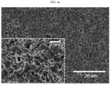
- the scanning electron microscopic (SEM) image of the surface of the separator is shown in FIG. 4a .
- a separator was obtained in the same manner as Example 1, except that PAN was not used, and Al 2 O 3 , PVAc, PMMA, PAN and the dispersing agent (tannic acid) were introduced to acetone at a weight ratio of 80:15:4:1 to obtain slurry for forming a porous coating layer.
- the scanning electron microscopic (SEM) image of the surface of the separator is shown in FIG. 4b .
- a separator was obtained in the same manner as Example 1, except that PAN was not used, and Al 2 O 3 , PVAc, PMMA, PAN and the dispersing agent (tannic acid) were introduced to acetone at a weight ratio of 80:9.5:9.5:1 to obtain slurry for forming a porous coating layer.
- the scanning electron microscopic (SEM) image of the surface of the separator is shown in FIG. 4c .
- Al 2 O 3 (D 50 : 500 nm), PVAc (Mw: 800,000, Tg: 40°C), PMMA (Mw: 130,000, Tg: 116°C) and a dispersing agent (tannic acid) were introduced to acetone to obtain the first slurry.
- PVAc Mw: 800,000, Tg: 40°C
- PMMA Mw: 130,000, Tg: 116°C
- a dispersing agent titanium acid
- the second slurry had a concentration of 18 wt%, and the weight ratio of Al 2 O 3 , PVAc, PMMA, PAN and the dispersing agent (tannic acid) in the second slurry was 80: 16:2: 1: 1.
- the slurry was applied onto a separator (polyethylene, porosity 45%, thickness 16 ⁇ m, air permeability 100 sec/100 cc) at a loading amount of 13.5 g/m 2 based on the area of the separator, followed by drying. The drying was carried out at 23°C under a humidified condition of a relative humidity of 45%. Then, the resultant product was cut into a size of 60 mm (length) x 25 mm (width) to obtain a separator.
- the resultant separator had a thickness of 25 ⁇ m.
- Natural graphite, SBR and CMC (weight ratio 90:9:1) were introduced to water to obtain negative electrode slurry.
- the negative electrode slurry was applied onto copper foil (thickness 10 ⁇ m) at a loading amount of 125 mg/cm 2 , followed by drying. Then, the resultant structure was pressed to a thickness of 90 ⁇ m and cut into a size of 50 mm (length) x 25 mm (width) to obtain a negative electrode.
- Each of the separators according to Examples and Comparative Examples was cut into a size of 60 mm (length) x 25 mm (width).
- the negative electrode prepared as described above was laminated with each separator by using a press at 60°C under 6.5 MPa to obtain a specimen.
- the obtained specimen was attached and fixed to a glass plate by using a double-sided adhesive tape in such a manner that the negative electrode might face the glass plate.
- the separator portion of the specimen was peeled at 25°C and a rate of 300 m/min with an angle of 180°, and the strength at this time was measured.
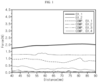
- the results of determination of the adhesion between the separator and the negative electrode is shown in the following Table 1 and FIG. 1 .
- A is a point interval at the initial stage before each separator is allowed stand at high temperature
- B is a point interval at the final stage after each separator is allowed stand at high temperature
- the separators of Examples 1 and 2 according to the present disclosure ensure a level of air permeability applicable to a separator for an electrochemical device.
- the separators according to Examples 1 and 2 show improved adhesion to the electrode and improved heat shrinkage as compared to the separators according to Comparative Examples 1-5.
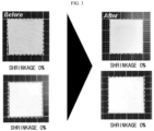
- FIG. 3 shows the photographic images of the separator according to Example 1 before and after the evaluation of heat shrinkage.
- the separator according to Example 1 shows a shrinkage of 0% in both tests.
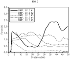
- Table 2 Specimen No. of Comp. Ex. 2 Mean Force (N) #1 1.192 #2 0.285 #3 0.048 #4 0.815 #5 1.084
- separator specimen #1 to separator specimen #5 derived from the separator obtained from Comparative Example 2 shows low uniformity in terms of the adhesion depending on the distance of each specimen.
- the results of the mean force calculated from each specimen in Table 2 it is difficult to reproduce constant adhesion.
- FIG. 4a the SEM images of the separators according to Examples 2-4 and Comparative Example 4 are shown in FIG. 4a , FIG. 4b , FIG. 4c and FIG. 4d , respectively. It can be determined from the SEM images that as the content of PMMA is increased, phase separation of the binder resin composition toward the surface of the separator is deteriorated, and thus the content of the binder resin composition at the surface portion is low. Therefore, it can be seen from the results that an excessively high content of the second binder resin, such as PMMA, may cause degradation of the adhesion.
- the second binder resin such as PMMA
Landscapes
- Chemical & Material Sciences (AREA)
- Chemical Kinetics & Catalysis (AREA)
- Electrochemistry (AREA)
- General Chemical & Material Sciences (AREA)
- Engineering & Computer Science (AREA)
- Inorganic Chemistry (AREA)
- Materials Engineering (AREA)
- Manufacturing & Machinery (AREA)
- Composite Materials (AREA)
- Cell Separators (AREA)
Abstract
Description
- The present application claims priority to
Korean Patent Application No. 10-2020-0041791 filed on April 6, 2020 - As technological development and needs for mobile instruments have been increased, secondary batteries as energy sources have been in rapidly increased in demand. Recently, use of secondary batteries as power sources for electric vehicles (EV), hybrid electric vehicles (HEV), or the like, have been realized. Accordingly, active studies have been conducted about secondary batteries capable of meeting various needs. Particularly, there is a high need for lithium secondary batteries having high energy density, high discharge voltage and output stability. More particularly, it is required for lithium secondary batteries used as power sources for electric vehicles and hybrid electric vehicles to have high output characteristics so that they may realize a high output in a short time. A polyolefin-based microporous film used conventionally as a separator for an electrochemical device shows a severe heat shrinking behavior at a temperature of 100°C or higher due to its material property and a characteristic during its manufacturing process, including orientation, thereby causing a short-circuit between a positive electrode and a negative electrode. To overcome such problems, recently, there has been applied a separator having a porous coating layer including a mixture containing inorganic particles and a binder polymer on at least one surface of a separator substrate, such as a polyolefin-based microporous membrane, having a plurality of pores. In general, the binder polymer used for the porous coating layer includes a PVDF-based binder resin including vinylidene as a polymerization unit. However, when using such a PVDF-based binder resin, there is a limitation in realization of high adhesive property. Therefore, there is a need for developing a binder resin composition suitable for a binder resin of a porous coating layer of a separator.
- The present disclosure is designed to solve the problems of the related art, and therefore the present disclosure is directed to providing a separator for an electrochemical device which has improved adhesion to an electrode and shows a low shrinkage, and a method for manufacturing the same. The present disclosure is also directed to providing a binder resin composition used for the separator. It will be easily understood that the objects and advantages of the present disclosure may be realized by the means shown in the appended claims and combinations thereof.
- According to the first embodiment of the present disclosure, there is provided a separator for an electrochemical device which includes a porous separator substrate and a porous coating layer formed on the surface of the porous separator substrate,
- wherein the porous coating layer includes inorganic particles and a binder resin at a weight ratio of about 50:50-99:1,
- the binder resin includes a first binder resin and a second binder resin,
- the first binder resin is an ethylenic polymer resin having a glass transition temperature (Tg) of 30-60°C and containing a polar group, and
- the second binder resin is an acrylic binder resin having a glass transition temperature (Tg) of 80-120°C.
- According to the second embodiment of the present disclosure, there is provided the separator for an electrochemical device as defined in the first embodiment, wherein the binder resin further includes a third binder resin which has a molecular weight (Mw) of 500,000 or less and is a vinylic polymer having a cyano group bound to the backbone thereof.
- According to the third embodiment of the present disclosure, there is provided the separator for an electrochemical device as defined in the first or the second embodiment, wherein the first binder resin is used in an amount of 50-90 wt% based on 100 wt% of the binder resin, and the second binder resin is used in an amount of 10-50 wt% based on 100 wt% of the binder resin.
- According to the fourth embodiment of the present disclosure, there is provided the separator for an electrochemical device as defined in any one of the first to the third embodiments, wherein the third binder resin is used in an amount of 6 wt% or less based on 100 wt% of the binder resin.
- According to the fifth embodiment of the present disclosure, there is provided the separator for an electrochemical device as defined in any one of the first to the fourth embodiments, wherein the first binder resin has a molecular weight (Mw) of 100,000-500,000 and includes polyvinyl acetate (PVAc) represented by the following Chemical Formula 1:

- According to the sixth embodiment of the present disclosure, there is provided the separator for an electrochemical device as defined in any one of the first to the fifth embodiments, wherein the second binder resin includes polymethyl methacrylate (PMMA) represented by the following Chemical Formula 2:

- According to the seventh embodiment of the present disclosure, there is provided the separator for an electrochemical device as defined in any one of the second to the sixth embodiments, wherein the third binder resin includes polyacrylonitrile (PAN).
- According to the eighth embodiment of the present disclosure, there is provided a separator for an electrochemical device which includes a porous separator substrate and a porous coating layer formed on the surface of the porous separator substrate,
- wherein the porous coating layer includes inorganic particles and a binder resin at a weight ratio of about 50:50-99:1,
- the binder resin includes a first binder resin, a second binder resin and a third binder resin,
- the first binder resin has a glass transition temperature (Tg) of 30-60°C and includes polyvinyl acetate (PVAc),
- the second binder resin has a glass transition temperature (Tg) of 80-120°C and includes polymethyl methacrylate (PMMA), and
- the third binder resin includes polyacrylonitrile (PAN).
- In addition, according to the ninth embodiment of the present disclosure, there is provided an electrochemical device including a positive electrode, a negative electrode and a separator interposed between the positive electrode and the negative electrode, wherein the separator is the same as defined in any one of the first to the eighth embodiments.
- In addition, according to the tenth embodiment of the present disclosure, there is provided a lithium-ion secondary battery including the electrochemical device as defined in the ninth embodiment.
- The separator obtained by using the binder resin composition according to the present disclosure shows high adhesion between an electrode and the separator, even when any separate adhesive layer is not disposed on the surface of the separator. In addition, the separator shows higher adhesion to an electrode, as compared to a separator using a fluorinated binder resin, such as polyvinylidene fluoride, used conventionally in the art. Therefore, when introducing the separator according to the present disclosure to a battery, it is possible to manufacture an electrode assembly under a mild temperature and pressure condition, to improve the productivity of assemblage, to reduce defect generation, and thus to increase the yield. In addition, since the separator according to the present disclosure has no separate adhesive layer, it is possible to provide low interfacial resistance between the separator and an electrode. Further, the separator shows high affinity to an electrolyte, as compared to a semi-crystalline polymer, such as a fluorinated binder resin, and thus improves the output characteristics of a battery.
- The accompanying drawings illustrate a preferred embodiment of the present disclosure and together with the foregoing disclosure, serve to provide further understanding of the technical features of the present disclosure, and thus, the present disclosure is not construed as being limited to the drawing. Meanwhile, shapes, sizes, scales or proportions of some constitutional elements in the drawings may be exaggerated for the purpose of clearer description.
-
FIG. 1 shows the result of evaluation of the adhesion of the separator according to Examples and that of Comparative Examples. -
FIG. 2 shows the result of determination of the peel strength of the separator specimen obtained according to Comparative Example 2. -
FIG. 3 shows the result of evaluation of the shrinkage of each of the separators according to Examples 1 and 2. -
FIG. 4a ,FIG. 4b ,FIG. 4c andFIG. 4d show the scanning electron microscopic (SEM) images of the separator surfaces of Examples 2-4 and Comparative Example 4, respectively. - Hereinafter, preferred embodiments of the present disclosure will be described in detail with reference to the accompanying drawings. Prior to the description, it should be understood that the terms used in the specification and the appended claims should not be construed as limited to general and dictionary meanings, but interpreted based on the meanings and concepts corresponding to technical aspects of the present disclosure on the basis of the principle that the inventor is allowed to define terms appropriately for the best explanation. Therefore, the description proposed herein is just a preferable example for the purpose of illustrations only, not intended to limit the scope of the disclosure, so it should be understood that other equivalents and modifications could be made thereto without departing from the scope of the disclosure.
- Throughout the specification, the expression `a part includes, comprises an element' does not preclude the presence of any additional elements but means that the part may further include the other elements.
- As used herein, the terms 'approximately', 'substantially', or the like, are used as meaning contiguous from or to the stated numerical value, when an acceptable preparation and material error unique to the stated meaning is suggested, and are used for the purpose of preventing an unconscientious invader from unduly using the stated disclosure including an accurate or absolute numerical value provided to help understanding of the present disclosure.
- As used herein, the expression `A and/or B' means `A, B or both of them'.
- Unless otherwise stated, temperature is expressed in the unit of a Celsius degree, and content or content ratio is expressed on the weight basis.
- The terms, 'top', 'bottom', 'left' and 'right' represent positions or directions in drawings to which reference is made, and are not used for limitary purposes.
- Specific terms used in the following description are for the convenience of description and understanding, and the scope of the present disclosure is not limited thereto. Such terms include the above-listed words, derivatives thereof and synonyms thereof.
- The present disclosure relates to a binder resin composition used for manufacturing a separator. The present disclosure also relates to a separator including the binder resin composition. In addition, the present disclosure relates to a method for manufacturing the separator.
- Herein, the electrochemical device is a system in which chemical energy is converted into electrical energy through electrochemical reactions, has a concept including a primary battery and a secondary battery, wherein the secondary battery is capable of charging and discharging and has a concept covering a lithium-ion battery, a nickelcadmium battery, a nickel-metal hydride battery, or the like.
- According to the present disclosure, the separator functions as an ion-conducting barrier which allows ions to pass therethrough, while interrupting an electrical contact between a negative electrode and a positive electrode. The separator has a plurality of pores formed therein, and the pores are interconnected preferably so that gases or liquids may pass from one surface of the separator to the other surface of the separator.
- According to an embodiment of the present disclosure, the separator includes a porous separator substrate including a polymer material, and a porous coating layer formed on at least one surface of the substrate, wherein the porous coating layer includes inorganic particles and a binder resin. In the porous coating layer, the inorganic particles are bound to one another by means of the binder resin. And, the porous coating layer may have a porous structure including pores derived from the interstitial volumes formed among the inorganic particles.
- The porous coating layer includes a binder resin and inorganic particles, has a plurality of micropores therein, wherein the micropores are interconnected with one another, and shows structural characteristics as a porous layer through which gases or liquids pass from one surface to the other surface. According to an embodiment of the present disclosure, the porous coating layer includes the binder resin and inorganic particles at a weight ratio of 50:50-1:99. The ratio may be controlled suitably within the above-defined range. For example, the binder resin may be used in an amount of 50 wt% or less, 40 wt% or less, or 30 wt% or less, based on 100 wt% of the combined weight of the binder resin and inorganic particles. In addition, within the above-defined range, the binder resin may be used in an amount of 1 wt% or more, 5 wt% or more, or 10 wt% or more. According to the present disclosure, the porous coating layer preferably has a porous structure with a view to ion permeability. According to an embodiment of the present disclosure, when the content of the binder resin is less than 1 wt%, the adhesion between the separator and an electrode is not sufficient. When the content of the binder resin is excessively high, porosity may be degraded, and the battery using the separator shows increased resistance to cause degradation of the electrochemical characteristics of the battery.
- According to an embodiment of the present disclosure, in the porous coating layer, the inorganic particles are bound to one another and integrated with one another by means of a polymer resin, wherein the interstitial volumes among the inorganic particles may form pores. As used herein, `interstitial volume' means a space defined by the inorganic particles facing each other substantially in a closely packed or densely packed structure of the inorganic particles.
- According to an embodiment of the present disclosure, the porous coating layer may have a porosity of 40-70 vol%. Within the above-defined range, the porosity may be 40 vol% or more, or 45 vol% or more. In combination with this or independently from this, the porosity may be 70 vol% or less, or 65 vol% or less. Considering ion conductivity, i.e. in order to ensure a sufficient path through which ions can pass, the porosity may be controlled to 40 vol% or more. In addition, in order to ensure heat resistance and adhesiveness, the porosity may be controlled to 65 vol% or less. Therefore, considering such electrochemical characteristics, the porosity of the porous coating layer may be controlled suitably within the above-defined range.
- Meanwhile, according to the present disclosure, the porous coating layer may have a total thickness controlled suitably within a range of 1-10 µm. The total thickness of the porous coating layer is the sum of the thicknesses of the porous coating layers formed on the surfaces of all sides of the separator substrate. If a porous coating layer is formed merely on one surface of the separator substrate, the thickness of the porous coating layer may satisfy the above-defined range. If porous coating layers are formed on both surfaces of the separator substate, the sum of the thicknesses of both porous coating layers may satisfy the above-defined range. When the thickness of the porous coating layer is less than 1 µm, it is not possible to obtain a sufficient effect of improving heat resistance due to an excessively small amount of inorganic particles contained in the porous coating layer. Meanwhile, when the thickness of the porous coating layer is excessively thicker than the above-defined range, the separator has a large thickness, thereby making it difficult to manufacture a thin battery and to improve the energy density of a battery.
- Meanwhile, according to an embodiment of the present disclosure, the porous coating layer includes inorganic particles and a binder resin. According to the present disclosure, the binder resin includes a first binder resin and a second binder resin. According to the present disclosure, the binder resin may further include a third binder resin. Among the binder resin, the first binder resin may be used in an amount of about 50-90 wt%. The first binder resin shows a relatively low glass transition temperature (Tg). Thus, when the content of the first binder resin is larger than 90 wt%, it is possible to obtain high adhesion partially, but it is difficult to ensure uniform adhesion throughout the whole surface of the separator. In addition, the separators obtained by using such an excessive amount of the first binder show a deviation in adhesion, thereby making it difficult to ensure uniform reproducibility. On the contrary, when the content of the first binder resin is less than 50 wt%, it is difficult to realize high adhesion characteristics due to such a low amount of the first binder resin.
- Meanwhile, the second binder resin may be used in an amount of 10-50 wt%. The second binder resin shows a relatively higher glass transition temperature as compared to the first binder resin. Thus, when the second binder resin is used within the above-defined range, it is possible to solve the problem of non-uniform adhesion caused by such a relatively low Tg of the first binder resin.
- Meanwhile, the third binder resin may be used in an amount of about 6 wt% or less, or 5 wt% or less, based on 100 wt% of the binder resin. It is possible to enhance the effect of improving adhesion through the addition of the third binder resin. However, when the third binder resin is introduced in an excessive amount, viscosity is increased to cause deterioration of phase separation, and thus a desired level of adhesion may not be ensured. Therefore, it is preferred to control the content of the third binder resin within the above-defined range in order to ensure suitable adhesion and to prevent an increase in viscosity.
- The first binder resin may include an ethylenic polymer resin containing a polar group. According to an embodiment of the present disclosure, the first binder resin has a glass transition temperature (Tg) of 30-60°C. Meanwhile, the first binder resin may have a molecular weight (Mw) of 100,000-500,000. According to an embodiment of the present disclosure, the ethylenic polymer resin containing a polar group may include polyvinyl acetate (PVAc) represented by the following
Chemical Formula 1, wherein n is an integer of 1 or more.
- The second binder resin includes an acrylic binder resin, and the acrylic binder resin has a glass transition temperature (Tg) of 80-120°C. When the second binder resin has a glass transition temperature lower than the drying temperature as described hereinafter, the binder resin may be distributed non-homogeneously, and for example, the binder resin may be distributed in such a manner that it may be concentrated locally in the porous coating layer. On the contrary, when the glass transition temperature is higher than 120°C, it is higher than the temperature applied to the electrode-separator lamination process as described hereinafter. Therefore, it is difficult to ensure a desired level of adhesion. Meanwhile, the first binder resin may have a molecular weight (Mw) of 100,000-500,000. According to an embodiment of the present disclosure, the acrylic binder resin may include a C1-C8 alkyl acrylate and/or alkyl methacrylate as a monomer. Particular examples of the alkyl acrylate include at least one selected from methyl acrylate, ethyl acrylate, isopropyl acrylate, n-butyl acrylate, isobutyl acrylate, cyclohexyl acrylate and 2-ethylhexyl acrylate. In addition, particular examples of the alkyl methacrylate include at least one selected from methyl methacrylate, ethyl methacrylate, isopropyl methacrylate, n-butyl methacrylate, isobutyl methacrylate, cyclohexyl methacrylate and 2-ethylhexyl methacrylate. According to an embodiment of the present disclosure, polymethyl methacrylate (PMMA) may be used as the second binder resin. Herein, PMMA may be represented by the following
Chemical Formula 2, wherein x is an integer of 1 or more.
- Meanwhile, according to an embodiment of the present disclosure, the third binder resin is a vinylic polymer containing a cyano group bound to the backbone thereof, and the vinylic polymer has a molecular weight (Mw) of 500,000 or less. The third binder resin uses dimethyl formamide (DMF) or N-methyl pyrrolidone (NMP) as a solvent, and preferably has a low molecular weight of 500,000 or less considering the solubility to the solvent. According to an embodiment of the present disclosure, the third binder resin may include polyacrylonitrile (PAN) that may be represented by the following
Chemical Formula 3, wherein n is an integer of 1 or more.
- According to the present disclosure, the term `molecular weight' refers to weight average molecular weight (Mw). According to an embodiment of the present disclosure, the molecular weight (Mw) may be determined by using gel permeation chromatography (GPC). For example, 200 mg of a polymer resin to be analyzed is diluted in 200 mL of a solvent, such as tetrahydrofuran (THF), to prepare a sample having a concentration of about 1000 ppm, and the molecular weight may be determined by using an Agilent 1200 series GPC instrument at a flow rate of 1 mL/min through a refractive index (RI) detector.
- In addition, besides the first to the third binder resins, the porous coating layer may further include at least one fourth binder resin selected from the group consisting of a vinylidene-containing fluorinated binder resin, polyvinyl pyrrolidone, polyethylene oxide, polyarylate, cyanoethyl pullulan, cyanoethyl polyvinyl alcohol, cyanoethyl cellulose, cyanoethyl sucrose and pullulan, if necessary. The fourth binder resin may be present in an amount of 10 wt% or less, 5 wt% or less, or 1 wt% or less, based on 100 wt% of the total weight of the binder resins contained in the porous coating layer.
- According to an embodiment of the present disclosure, there is no particular limitation in the inorganic particles, as long as they are electrochemically stable. In other words, there is no particular limitation in the inorganic particles that may be used herein, as long as they cause no oxidation and/or reduction in the range (e.g. 0-5V based on Li/Li+) of operating voltage of an applicable electrochemical device. Particularly, when using inorganic particles having a high dielectric constant as inorganic particles, it is possible to improve the ion conductivity of an electrolyte by increasing the dissociation degree of an electrolyte salt, such as a lithium salt, in a liquid electrolyte.
- For the above-mentioned reasons, the inorganic particles may be inorganic particles having a dielectric constant of 5 or more, preferably 10 or more. Non-limiting examples of the inorganic particles having a dielectric constant of 5 or more may include at least one selected from the group consisting of BaTiO3, Pb(Zr,Ti)O3 (PZT), Pb1-xLaxZr1-yTiyO3 (PLZT, wherein 0 < x < 1, 0 < y < 1), Pb(Mg1/3Nb2/3)O3PbTiO3 (PMN-PT), hafnia (HfO2), SrTiO3, SnO2, CeO2, MgO, Mg(OH)2, NiO, CaO, ZnO, ZrO2, SiO2, Y2O3, Al2O3, SiC, Al(OH)3, AlOOH and TiO2.
- In addition, inorganic particles having lithium-ion transportability, i.e. inorganic particles containing lithium elements, and not storing lithium but transporting lithium ions, may be used as inorganic particles. Non-limiting examples of the inorganic particles having lithium-ion transportability include lithium phosphate (Li3PO4), lithium titanium phosphate (LixTiy(PO4)3, 0 < x < 2, 0 < y < 3), lithium aluminum titanium phosphate (LixAlyTiz(PO4)3, 0 < x < 2, 0 < y < 1, 0 < z < 3), (LiAlTiP)xOy-based glass (1 < x < 4, 0 < y < 13), such as 14Li2O-9Al2O3-38TiO2-39P2O5, lithium lanthanum titanate (LixLayTiO3, 0 < x < 2, 0 < y < 3), lithium germanium thiophosphate (LixGeyPzSw, 0 < x < 4, 0 < y < 1, 0 < z < 1, 0 < w < 5), such as Li3.25Ge0.25P0.75S4, lithium nitride (LixNy, 0 < x < 4, 0 < y < 2), such as Li3N, SiS2-based glass (LixSiySz, 0 < x < 3, 0 < y < 2, 0 < z < 4), such as Li3PO4-Li2S-SiS2, and P2S5-based glass (LixPySz, 0 < x < 3, 0 < y < 3, 0 < z < 7), such as LiI-Li2S-P2S5, or a mixture thereof.
- Further, the inorganic particles may have an average particle diameter (D50) of 10 nm to 5 µm. Meanwhile, when the particles have an average particle diameter (D50) of less than 10 nm, the inorganic particles have an excessively large surface area to cause degradation of dispersibility of the inorganic particles in slurry for forming a porous coating layer during the preparation of the slurry. Meanwhile, as the particle diameter of the inorganic particles is increased, the mechanical properties of the separator may be degraded. Therefore, it is preferred that the particle diameter of the inorganic particles does not exceed 5 µm.
- According to an embodiment of the present disclosure, the particle diameter (D50) of the inorganic particles refers to an integrated value at 50% from the side of smaller particles calculated based on the results of determination of the particle size distribution of particles after classification using a particle size analyzer used conventionally in the art. Such particle size distribution can be determined by a diffraction or scattering intensity pattern generated upon the contact of light with the particles. As a particle size distribution analyzer, Microtrac 9220FRA or Microtrac HRA available from Nikkiso may be used.
- As described above, the separator according to the present disclosure includes a porous separator substrate including a polymer material. The separator substrate may be a porous film including a polymer resin, such as a porous polymer film made of a polyolefin material including polyethylene, polypropylene, or the like. The separator substrate may be molten at least partially, when the battery temperature is increased, and thus blocks the pores to induce shut-down. According to an embodiment of the present disclosure, the separator substrate may have a porosity of 40-70 vol%. Meanwhile, the pores of the separator substrate may have a diameter of about 10-70 nm based on the largest diameter of the pores. According to the present disclosure, the separator substrate may have a thickness of 5-14 µm with a view to thin filming and high energy density of an electrochemical device.
- According to the present disclosure, the term 'porosity' means a volume occupied by pores based on the total volume of a structure, is expressed in the unit of percentage (%), and may be used exchangeably with the terms, such as pore ratio, porous degree, or the like. According to the present disclosure, the method for determining porosity is not particularly limited. According to an embodiment of the present disclosure, the porosity may be determined by the Brunauer-Emmett-Teller (BET) method using nitrogen gas or Hg porosimetry and according to ASTM D-2873. Further, the net density of a separator may be calculated from the density (apparent density) of the separator and the compositional ratio of ingredients contained in the separator and density of each ingredient, and the porosity of the separator may be calculated from the difference between the apparent density and the net density.
- Meanwhile, according to an embodiment of the present disclosure, the pore size, pore size distribution and mean pore size (nm) may be determined by using a capillary flow porometer. The capillary flow porometer is based on the process including wetting the pores of a separator with a liquid having a known surface tension, and applying pneumatic pressure thereto to measure the bubble point (max pore) where the initial flux is generated. Particular examples of the capillary flow porometer include CFP-1500-AE available from Porous Materials Co., or the like.
- Meanwhile, according to an embodiment of the present disclosure, the separator substrate may further include at least one polymer resin selected from polyethylene terephthalate, polybutylene terephthalate, polyacetal, polyamide, polycarbonate, polyimide, polyetherether ketone, polyether sulfone, polyphenylene oxide, polyphenylene sulfide and polyethylene naphthalene, if necessary, for improving durability, or the like.
- According to an embodiment of the present disclosure, the separator substrate may be a porous polymer film obtained by the method as described hereinafter, and may be a sheet of monolayer film or a multilayer film formed by lamination of two or more sheets. When two or more sheets are laminated, each layer preferably has the above-described characteristics in terms of its ingredients.
- The methods for manufacturing the separator are not particularly limited, as long as the methods can provide the above-described structure. For example, the separator may be obtained by introducing the binder resin composition and inorganic particles to a suitable solvent to prepare slurry for forming a porous coating layer, and applying the slurry to at least one surface of the polymer substrate, followed by drying. According to an embodiment of the present disclosure, the drying may be carried out by allowing the coated polymer substrate under a relative humidity of about 40-80% for a predetermined time so that the binder resin may be solidified. Herein, phase separation of the binder resin is induced. As the solvent migrates toward the surface portion of the inorganic coating layer and the binder resin migrates toward the surface portion of the inorganic coating layer along with the migration of the solvent, the content of the binder resin is increased at the surface portion of the porous coating layer. Meanwhile, at the portion under the surface portion of the porous coating layer, pores are formed due to the interstitial volumes among the inorganic particles so that the porous coating layer may be provided with porous property. According to an embodiment of the present disclosure, particular examples of the solvent may include acetone, methyl ethyl ketone, N-methyl pyrrolidone, polar amide solvent, such as dimethyl acetamide or diethyl formamide, and such solvents may be used alone or in combination.
- Meanwhile, the third binder resin has relatively lower solubility to the solvent, such as acetone. Therefore, according to an embodiment of the present disclosure, each of the first slurry, including inorganic particles and the first and the second binder resins, and a polymer solution including the third binder resin are prepared separately from each other, and then the first slurry and the polymer solution may be mixed with each other to prepare slurry for forming a porous coating layer. Herein, the polymer solution may include at least one solvent selected from dimethyl formamide (DMF), N-methyl-2-pyrrolidone (NMP), dimethyl acetamide (DMAC), tetrahydrofuran (THF), methyl isobutyl ketone (MIBK), methyl ethyl ketone (MEK), or the like.
- The slurry for forming a porous coating layer may be applied through a conventional coating process, such as Meyer bar coating, die coating, reverse roll coating, gravure coating, or the like. When forming the porous coating layers on both surfaces of the separator substrate, the coating solution may be applied to a single surface sequentially, and then humidified phase separation and drying may be carried out. However, it is preferred in terms of productivity that the coating solution is applied to both surfaces of the separator substrate at the same time, and then humidified phase separation and drying are carried out.
- According to an embodiment of the present disclosure, the secondary battery includes: an electrode assembly including a negative electrode, a positive electrode and a separator interposed between the negative electrode and the positive electrode; and an electrolyte. The electrode assembly may be received in a battery casing, and the electrolyte may be injected thereto to provide a battery.
- According to the present disclosure, the positive electrode includes a positive electrode current collector, and a positive electrode active material layer formed on at least one surface of the current collector and containing a positive electrode active material, a conductive material and a binder resin. The positive electrode active material may include any one selected from: layered compounds, such as lithium manganese composite oxide (LiMn2O4, LiMnO2, etc.), lithium cobalt oxide (LiCoO2) and lithium nickel oxide (LiNiO2), or those compounds substituted with one or more transition metals; lithium manganese oxides such as those represented by the chemical formula of Li1+xMn2-xO4 (wherein x is 0-0.33), LiMnO3, LiMn2O3 and LiMnO2; lithium copper oxide (Li2CuO2); lithium vanadium oxides such as LiVsOs, LiV3O4, V2O5 or Cu2V2O7; Ni-site type lithium nickel oxides represented by the chemical formula of LiNi1-xMxO2 (wherein M is Co, Mn, Al, Cu, Fe, Mg, B or Ga, and x is 0.01-0.3); lithium manganese composite oxides represented by the chemical formula of LiMn2-xMxO2 (wherein M is Co, Ni, Fe, Cr, Zn or Ta, and x is 0.01-0.1) or Li2Mn3MO8 (wherein M is Fe, Co, Ni, Cu or Zn); LiMn2O4 in which Li is partially substituted with an alkaline earth metal ion; disulfide compounds; and Fe2(MoO4)3; or a mixture of two or more of them.
- According to the present disclosure, the negative electrode includes a negative electrode current collector, and a negative electrode active material layer formed on at least one surface of the current collector and containing a negative electrode active material, a conductive material and a binder resin. The negative electrode may include, as a negative electrode active material, any one selected from: lithium metal oxide; carbon such as non-graphitizable carbon or graphite-based carbon; metal composite oxides, such as LixFe2O3 (0 ≤ x ≤ 1), LixWO2(0 ≤ x ≤ 1), SnxMe1-xMe'yOz (Me: Mn, Fe, Pb, Ge; Me': Al, B, P, Si, elements of
Group - According to an embodiment of the present disclosure, the conductive material may be any one selected from the group consisting of graphite, carbon black, carbon fibers or metal fibers, metal powder, conductive whiskers, conductive metal oxides, activated carbon and polyphenylene derivatives, or a mixture of two or more of such conductive materials. More particularly, the conductive material may be any one selected from natural graphite, artificial graphite, Super-P, acetylene black, Ketjen black, channel black, furnace black, lamp black, thermal black, denka black, aluminum powder, nickel powder, zinc oxide, potassium titanate and titanium dioxide, or a mixture of two or more such conductive materials.
- The current collector is not particularly limited, as long as it causes no chemical change in the corresponding battery and has high conductivity. Particular examples of the current collector may include stainless steel, copper, aluminum, nickel, titanium, baked carbon, aluminum or stainless steel surface-treated with carbon, nickel, titanium or silver, or the like.
- The binder resin may be a polymer used conventionally for an electrode in the art. Non-limiting examples of the binder resin may include, but are not limited to: polyvinylidene fluoride-co-hexafluoropropylene, polyvinylidene fluoride-co-trichloroethylene, polymethyl methacrylate, polyethylhexyl acrylate, polybutyl acrylate, polyacrylonitrile, polyviny1 pyrro1idone, polyvinyl acetate, polyethylene-co-vinyl acetate, polyethylene oxide, polyarylate, cellulose acetate, cellulose acetate butyrate, cellulose acetate propionate, cyanoethylpullulan, cyanoethy1polyvinyla1cho1, cyanoethyl cellulose, cyanoethyl sucrose, pullulan, and carboxymethyl cellulose.
- According to the present disclosure, the electrolyte is a salt having a structure of A+B-, wherein A+ includes an alkali metal cation such as Li+, Na+, K+ or a combination thereof, and B- includes an anion such as PF6 -, BF4 -, Cl-, Br-, I-, ClO4 -, AsF6 -, CH3CO2 -, CF3SO3 -, N(CF3SO2)2 -, C(CF2SO2)3 - or a combination thereof, the salt being dissolved or dissociated in an organic solvent selected from propylene carbonate (PC), ethylene carbonate (EC), diethyl carbonate (DEC), dimethyl carbonate (DMC), dipropyl carbonate (DPC), dimethyl sulfoxide, acetonitrile, dimethoxyethane, diethoxyethane, tetrahydrofuran, N-methyl-2-pyrrolidone (NMP), ethyl methyl carbonate (EMC), gamma-butyrolactone (γ-butyrolactone), and mixtures thereof. However, the present disclosure is not limited thereto.
- In addition, the present disclosure provides a battery module which includes a battery including the electrode assembly as a unit cell, a battery pack including the battery module, and a device including the battery pack as an electric power source. Particular examples of the device include, but are not limited to: power tools driven by the power of an electric motor; electric cars, including electric vehicles (EV), hybrid electric vehicles (HEV), plug-in hybrid electric vehicles (PHEV), or the like; electric two-wheeled vehicles, including E-bikes and E-scooters; electric golf carts; electric power storage systems; or the like.
- Examples will be described more fully hereinafter so that the present disclosure can be understood with ease. The following examples may, however, be embodied in many different forms and should not be construed as limited to the exemplary embodiments set forth therein. Rather, these exemplary embodiments are provided so that the present disclosure will be thorough and complete, and will fully convey the scope of the present disclosure to those skilled in the art.
- First, Al2O3 (D50: 500 nm), PVAc (Mw: 150,000, Tg: 40°C), PMMA (Mw: 130,000, Tg: 116°C) and a dispersing agent (tannic acid) were introduced to acetone to obtain the first slurry. Meanwhile, PAN (Mw: 150,000, Tg: 85°C, Tm: 320°C) was dissolved in DMF to prepare a polymer solution. Next, the first slurry was mixed with the polymer solution to prepare slurry for forming a porous coating layer (the second slurry). The second slurry had a concentration of 18 wt%, and the weight ratio of Al2O3, PVAc, PMMA, PAN and the dispersing agent (tannic acid) in the second slurry was 80:16:2:1:1. The slurry was applied onto a separator (polyethylene, porosity 45%, thickness 16 µm, air permeability 100 sec/100 cc) at a loading amount of 13.5 g/m2 based on the area of the separator, followed by drying. The drying was carried out at 23°C under a humidified condition of a relative humidity of 45%. Then, the resultant product was cut into a size of 60 mm (length) x 25 mm (width) to obtain a separator. The resultant separator had a thickness of 25 µm.
- A separator was obtained in the same manner as Example 1, except that PAN was not used, and Al2O3, PVAc, PMMA, PAN and the dispersing agent (tannic acid) were introduced to acetone at a weight ratio of 80:17:2:1 to obtain slurry for forming a porous coating layer. The scanning electron microscopic (SEM) image of the surface of the separator is shown in
FIG. 4a . - A separator was obtained in the same manner as Example 1, except that PAN was not used, and Al2O3, PVAc, PMMA, PAN and the dispersing agent (tannic acid) were introduced to acetone at a weight ratio of 80:15:4:1 to obtain slurry for forming a porous coating layer. The scanning electron microscopic (SEM) image of the surface of the separator is shown in
FIG. 4b . - A separator was obtained in the same manner as Example 1, except that PAN was not used, and Al2O3, PVAc, PMMA, PAN and the dispersing agent (tannic acid) were introduced to acetone at a weight ratio of 80:9.5:9.5:1 to obtain slurry for forming a porous coating layer. The scanning electron microscopic (SEM) image of the surface of the separator is shown in
FIG. 4c . - First, Al2O3, PVDF-HFP (Mw: 400,000, Tm: 145°C), PVDF-CTFE (Mw: 400,000, Tm: 160°C) and a dispersing agent (tannic acid) were introduced to acetone at a weight ratio of 80:10:1 to obtain slurry for forming a porous coating layer. The resultant slurry was applied onto a separator (polyethylene, porosity 45%, thickness 16 µm) at a loading amount of 13.5 g/m2 based on the area of the separator, followed by drying. The drying was carried out at 23°C under a humidified condition of a relative humidity of 45%. Then, the resultant product was cut into a size of 60 mm (length) x 25 mm (width) to obtain a separator. The resultant separator had a thickness of 25 µm.
- First, Al2O3, PVAc and a dispersing agent were introduced to acetone at a weight ratio of 80:19:1 to obtain slurry for forming a porous coating layer. The resultant slurry was applied onto a separator (polyethylene, porosity 45%, thickness 16 µm) at a loading amount of 13.5 g/m2 based on the area of the separator, followed by drying. The drying was carried out at 23°C under a humidified condition of a relative humidity of 45%. Then, the resultant product was cut into a size of 60 mm (length) x 25 mm (width) to obtain a separator.
- First, Al2O3, PMMA and a dispersing agent were introduced to acetone at a weight ratio of 80:19:1 to obtain slurry for forming a porous coating layer. The resultant slurry was applied onto a separator (polyethylene, porosity 45%, thickness 16 µm) at a loading amount of 13.5 g/m2 based on the area of the separator, followed by drying. The drying was carried out at 23°C under a humidified condition of a relative humidity of 45%. Then, the resultant product was cut into a size of 60 mm (length) x 25 mm (width) to obtain a separator.
- First, Al2O3, PVAc, PMMA and a dispersing agent were introduced to acetone at a weight ratio of 80:6:13:1 to obtain slurry for forming a porous coating layer. The resultant slurry was applied onto a separator (polyethylene, porosity 45%, thickness 16 µm) at a loading amount of 13.5 g/m2 based on the area of the separator, followed by drying. The drying was carried out at 23°C under a humidified condition of a relative humidity of 45%. Then, the resultant product was cut into a size of 60 mm (length) x 25 mm (width) to obtain a separator. The scanning electron microscopic (SEM) image of the surface of the separator is shown in
FIG. 4d . - First, Al2O3 (D50: 500 nm), PVAc (Mw: 800,000, Tg: 40°C), PMMA (Mw: 130,000, Tg: 116°C) and a dispersing agent (tannic acid) were introduced to acetone to obtain the first slurry. Meanwhile, PAN (Mw: 150,000, Tg: 85°C, Tm: 320°C) was dissolved in DMF to prepare a polymer solution. Next, the first slurry was mixed with the polymer solution to prepare slurry for forming a porous coating layer (the second slurry). The second slurry had a concentration of 18 wt%, and the weight ratio of Al2O3, PVAc, PMMA, PAN and the dispersing agent (tannic acid) in the second slurry was 80: 16:2: 1: 1. The slurry was applied onto a separator (polyethylene, porosity 45%, thickness 16 µm, air permeability 100 sec/100 cc) at a loading amount of 13.5 g/m2 based on the area of the separator, followed by drying. The drying was carried out at 23°C under a humidified condition of a relative humidity of 45%. Then, the resultant product was cut into a size of 60 mm (length) x 25 mm (width) to obtain a separator. The resultant separator had a thickness of 25 µm.
- Natural graphite, SBR and CMC (weight ratio 90:9:1) were introduced to water to obtain negative electrode slurry. The negative electrode slurry was applied onto copper foil (
thickness 10 µm) at a loading amount of 125 mg/cm2, followed by drying. Then, the resultant structure was pressed to a thickness of 90 µm and cut into a size of 50 mm (length) x 25 mm (width) to obtain a negative electrode. - Each of the separators according to Examples and Comparative Examples was cut into a size of 60 mm (length) x 25 mm (width). The negative electrode prepared as described above was laminated with each separator by using a press at 60°C under 6.5 MPa to obtain a specimen. The obtained specimen was attached and fixed to a glass plate by using a double-sided adhesive tape in such a manner that the negative electrode might face the glass plate. Then, the separator portion of the specimen was peeled at 25°C and a rate of 300 m/min with an angle of 180°, and the strength at this time was measured. The results of determination of the adhesion between the separator and the negative electrode is shown in the following Table 1 and
FIG. 1 . Meanwhile, five separator specimens obtained by the same method as described in Comparative Example 2 were prepared and peeled at 25°C and a rate of 300 m/min with an angle of 180°, and the peel strength depending on distance was measured. The results are shown in the following Table 2 andFIG. 2 . - Each of the separators according to Examples and Comparative Examples was allowed to stand at 130°C for 0.5 hours, and the shrinkage of each separator was determined. The shrinkage was obtained by marking two points optionally on the separator and calculating an increase/decrease in the interval (point interval) between the two points according to the following
Formula 1.FIG. 2 show the photographic views illustrating the separators according to Examples 1 and 2, before and after the determination of the shrinkage. It can be seen from the results that the separators according to Examples 1 and 2 shows excellent shrinkage characteristics as determined by a shrinkage of 1% or less.
- In
Formula 1, A is a point interval at the initial stage before each separator is allowed stand at high temperature, and B is a point interval at the final stage after each separator is allowed stand at high temperature. - The following Table 1 shows the results obtained from the above-described tests.
[Table 1] Ex. 1 Ex. 2 Comp. Ex. 1 Comp. Ex. 2 Comp. Ex. 3 Comp. Ex. 4 Comp. Ex. 5 Ingredients and composition of binder resin composition PVAc/PM MA/PAN PVAc/PM MA (9:1, weight ratio) PVDF-HFP, PVDF-CTFE PVAc PMMA PVAc/ PMMA (2:8, weight ratio) PVAc/PM MA/PAN Thickness of separator (µm) 25 25 25 25 25 25 25 Air permeability of separator (sec/100cc) 356 240 300 264 220 189 460 Adhesion of separator with negative electrode (N) 1.907 1.270 0.857 0.048-1.192 0.053 0.292 0.350 Heat shrinkage of separator (%) 0 1 2 1 4 2 0 - As can be seen from Table 1, the separators of Examples 1 and 2 according to the present disclosure ensure a level of air permeability applicable to a separator for an electrochemical device. In addition, the separators according to Examples 1 and 2 show improved adhesion to the electrode and improved heat shrinkage as compared to the separators according to Comparative Examples 1-5. Meanwhile,
FIG. 3 shows the photographic images of the separator according to Example 1 before and after the evaluation of heat shrinkage. The separator according to Example 1 shows a shrinkage of 0% in both tests.[Table 2] Specimen No. of Comp. Ex. 2 Mean Force (N) #1 1.192 #2 0.285 #3 0.048 #4 0.815 #5 1.084 - Meanwhile, as can be seen from
FIG. 2 ,separator specimen # 1 toseparator specimen # 5 derived from the separator obtained from Comparative Example 2 shows low uniformity in terms of the adhesion depending on the distance of each specimen. In addition, as can be seen from the results of the mean force calculated from each specimen in Table 2, it is difficult to reproduce constant adhesion. - Meanwhile, the SEM images of the separators according to Examples 2-4 and Comparative Example 4 are shown in
FIG. 4a ,FIG. 4b ,FIG. 4c andFIG. 4d , respectively. It can be determined from the SEM images that as the content of PMMA is increased, phase separation of the binder resin composition toward the surface of the separator is deteriorated, and thus the content of the binder resin composition at the surface portion is low. Therefore, it can be seen from the results that an excessively high content of the second binder resin, such as PMMA, may cause degradation of the adhesion.
Claims (11)
- A separator for an electrochemical device which comprises a porous separator substrate and a porous coating layer formed on the surface of the porous separator substrate,wherein the porous coating layer comprises inorganic particles and a binder resin at a weight ratio of about 50:50-99:1,the binder resin comprises a first binder resin and a second binder resin,the first binder resin is an ethylenic polymer resin having a glass transition temperature (Tg) of 30-60°C and containing a polar group, andthe second binder resin is an acrylic binder resin having a glass transition temperature (Tg) of 80-120°C.
- The separator for an electrochemical device according to claim 1, wherein the binder resin further comprises a third binder resin which has a molecular weight (Mw) of 500,000 or less and is a vinylic polymer having a cyano group bound to the backbone thereof.
- The separator for an electrochemical device according to claim 1, wherein the first binder resin is used in an amount of 50-90 wt% based on 100 wt% of the binder resin, and the second binder resin is used in an amount of 10-50 wt% based on 100 wt% of the binder resin.
- The separator for an electrochemical device according to claim 2, wherein the third binder resin is used in an amount of 6 wt% or less based on 100 wt% of the binder resin.
- The separator for an electrochemical device according to claim 1, wherein the first binder resin has a molecular weight (Mw) of 100,000-500,000 and comprises polyvinyl acetate (PVAc) represented by the following Chemical Formula 1:

- The separator for an electrochemical device according to claim 1, wherein the second binder resin comprises polymethyl methacrylate (PMMA) represented by the following Chemical Formula 2:

- The separator for an electrochemical device according to claim 2, wherein the third binder resin comprises polyacrylonitrile (PAN).
- The separator for an electrochemical device according to claim 2, wherein the first binder resin has a molecular weight (Mw) of 100,000-500,000 and comprises polyvinyl acetate (PVAc) represented by the following Chemical Formula 1:

- A separator for an electrochemical device which comprises a porous separator substrate and a porous coating layer formed on the surface of the porous separator substrate,wherein the porous coating layer comprises inorganic particles and a binder resin at a weight ratio of about 50:50-99:1,the binder resin comprises a first binder resin, a second binder resin and a third binder resin,the first binder resin has a glass transition temperature (Tg) of 30-60°C and includes polyvinyl acetate (PVAc),the second binder resin has a glass transition temperature (Tg) of 80-120°C and includes polymethyl methacrylate (PMMA), andthe third binder resin comprises polyvinyl acetate (PVAc) .
- An electrochemical device comprising a positive electrode, a negative electrode and a separator interposed between the positive electrode and the negative electrode, wherein the separator is the same as defined in any one of claims 1 to 8.
- A lithium-ion secondary battery comprising the electrochemical device as defined in claim 10.
Applications Claiming Priority (2)
| Application Number | Priority Date | Filing Date | Title |
|---|---|---|---|
| KR20200041791 | 2020-04-06 | ||
| PCT/KR2021/004306 WO2021206431A1 (en) | 2020-04-06 | 2021-04-06 | Separator for electrochemical element and method for manufacturing same |
Publications (2)
| Publication Number | Publication Date |
|---|---|
| EP4131623A1 true EP4131623A1 (en) | 2023-02-08 |
| EP4131623A4 EP4131623A4 (en) | 2023-11-22 |
Family
ID=78023792
Family Applications (1)
| Application Number | Title | Priority Date | Filing Date |
|---|---|---|---|
| EP21783718.6A Pending EP4131623A4 (en) | 2020-04-06 | 2021-04-06 | ELECTROCHEMICAL ELEMENT SEPARATOR AND METHOD FOR PRODUCING THE SAME |
Country Status (6)
| Country | Link |
|---|---|
| US (1) | US12586868B2 (en) |
| EP (1) | EP4131623A4 (en) |
| JP (1) | JP7476339B2 (en) |
| KR (1) | KR20210124087A (en) |
| CN (1) | CN115336097B (en) |
| WO (1) | WO2021206431A1 (en) |
Cited By (1)
| Publication number | Priority date | Publication date | Assignee | Title |
|---|---|---|---|---|
| EP4135113A4 (en) * | 2020-04-14 | 2024-11-20 | LG Energy Solution, Ltd. | Separator for electrochemical device and method for manufacturing same |
Families Citing this family (2)
| Publication number | Priority date | Publication date | Assignee | Title |
|---|---|---|---|---|
| KR20240047634A (en) * | 2022-10-05 | 2024-04-12 | 주식회사 엘지에너지솔루션 | Separator for electrochemical device, manufacturing method thereof and including the same |
| WO2024146064A1 (en) * | 2023-01-04 | 2024-07-11 | 宁德时代新能源科技股份有限公司 | Binder, separator, electrode sheet, electrode assembly, battery cell, battery, and electric device |
Family Cites Families (27)
| Publication number | Priority date | Publication date | Assignee | Title |
|---|---|---|---|---|
| KR100324626B1 (en) | 2000-03-06 | 2002-02-27 | 박호군 | Composite electrodes and lithium secondary battery using gel-type polymer electrolytes, and its fabrication method |
| KR100470444B1 (en) | 2000-07-20 | 2005-02-07 | 조극래 | Manufacturing process and an apparatus for nonstoichiometric compounds of titanium, metal or nonferrous metal |
| KR100775310B1 (en) * | 2004-12-22 | 2007-11-08 | 주식회사 엘지화학 | Organic/inorganic composite microporous membrane and electrochemical device prepared thereby |
| KR100727248B1 (en) * | 2007-02-05 | 2007-06-11 | 주식회사 엘지화학 | Organic / inorganic composite membrane coated with porous active layer and electrochemical device |
| KR20120035858A (en) * | 2010-10-05 | 2012-04-16 | 주식회사 엘지화학 | A electrochemical device for progressing cycle characteristic |
| WO2012050152A1 (en) | 2010-10-13 | 2012-04-19 | 日立マクセル株式会社 | Separator for non-aqueous electrolyte battery and non-aqueous electrolyte battery |
| KR20130083211A (en) * | 2012-01-12 | 2013-07-22 | 주식회사 엘지화학 | A separator having porous coating and electrochemical device containing the same |
| KR20140139292A (en) * | 2013-05-27 | 2014-12-05 | 주식회사 엘지화학 | Separator and electrochemical device having the same |
| KR20150106810A (en) | 2013-11-21 | 2015-09-22 | 삼성에스디아이 주식회사 | Separators and secondary battery using the separator |
| WO2015076571A1 (en) | 2013-11-21 | 2015-05-28 | 삼성에스디아이 주식회사 | Separator coating agent composition, separator formed of coating agent composition, and battery using same |
| KR101938385B1 (en) * | 2014-12-08 | 2019-04-11 | 주식회사 엘지화학 | Separator with a layer of binder polymers for electrochemical device and Electrochemical device comprising the same |
| KR20160084063A (en) | 2015-01-05 | 2016-07-13 | 주식회사 우성이엠피 | Building interior with soundproofing and Heating surname |
| KR101751443B1 (en) * | 2015-10-13 | 2017-06-27 | 주식회사 엘지화학 | Separator having porous coating layer and electrochemical device having the same |
| KR102496375B1 (en) * | 2015-11-20 | 2023-02-06 | 삼성전자주식회사 | Electrode composite separator assembly for lithium battery and lithium battery including the same |
| US10734627B2 (en) | 2016-04-01 | 2020-08-04 | Lg Chen, Ltd. | Separator comprising an adhesion layer for an electrochemical device and an electrode assembly comprising the same |
| EP3246969B1 (en) | 2016-05-17 | 2018-12-12 | Samsung SDI Co., Ltd. | Separator for rechargeable battery and rechargeable lithium battery including the same |
| JP6334071B1 (en) * | 2016-09-21 | 2018-05-30 | 帝人株式会社 | Non-aqueous secondary battery separator and non-aqueous secondary battery |
| WO2019082359A1 (en) | 2017-10-26 | 2019-05-02 | 堺ディスプレイプロダクト株式会社 | Method and apparatus for manufacturing flexible oled device |
| EP3579301A4 (en) | 2017-11-24 | 2020-04-01 | LG Chem, Ltd. | METHOD FOR MANUFACTURING SEPARATOR, SEPARATOR THUS MANUFACTURED, AND ELECTROCHEMICAL ELEMENT COMPRISING SAID SEPARATOR |
| KR102714011B1 (en) * | 2017-12-22 | 2024-10-07 | 주식회사 엘지에너지솔루션 | A method for manufacturing a separator for an electrode device and a separator thereby |
| EP3506383B1 (en) | 2017-12-28 | 2020-02-12 | Samsung SDI Co., Ltd. | Battery module |
| KR102263460B1 (en) | 2018-01-05 | 2021-06-11 | 주식회사 엘지에너지솔루션 | Separator Comprising Binders Having Different Glass Transition Temperature and Method for Preparing the Same |
| KR102311810B1 (en) | 2018-09-21 | 2021-10-08 | 주식회사 엘지에너지솔루션 | Separator and electrochemical device containing the same |
| KR102437371B1 (en) * | 2018-09-28 | 2022-08-26 | 주식회사 엘지에너지솔루션 | A separator for an electrochemical device and a method for manufacturing the same |
| JP7166132B2 (en) | 2018-10-12 | 2022-11-07 | 株式会社荏原製作所 | SUBSTRATE CLEANING MEMBER AND SUBSTRATE CLEANING APPARATUS |
| CN109274685B (en) | 2018-11-02 | 2021-09-17 | 深圳壹账通智能科技有限公司 | Multi-system login method and device, computer equipment and storage medium |
| CN115398735B (en) * | 2020-04-14 | 2024-09-06 | 株式会社Lg新能源 | Composite separator for electrochemical device and method of making the same |
-
2021
- 2021-04-06 WO PCT/KR2021/004306 patent/WO2021206431A1/en not_active Ceased
- 2021-04-06 KR KR1020210044879A patent/KR20210124087A/en active Pending
- 2021-04-06 US US17/917,156 patent/US12586868B2/en active Active
- 2021-04-06 EP EP21783718.6A patent/EP4131623A4/en active Pending
- 2021-04-06 JP JP2022557180A patent/JP7476339B2/en active Active
- 2021-04-06 CN CN202180024703.6A patent/CN115336097B/en active Active
Cited By (1)
| Publication number | Priority date | Publication date | Assignee | Title |
|---|---|---|---|---|
| EP4135113A4 (en) * | 2020-04-14 | 2024-11-20 | LG Energy Solution, Ltd. | Separator for electrochemical device and method for manufacturing same |
Also Published As
| Publication number | Publication date |
|---|---|
| WO2021206431A1 (en) | 2021-10-14 |
| JP7476339B2 (en) | 2024-04-30 |
| US12586868B2 (en) | 2026-03-24 |
| KR20210124087A (en) | 2021-10-14 |
| CN115336097A (en) | 2022-11-11 |
| CN115336097B (en) | 2024-05-03 |
| EP4131623A4 (en) | 2023-11-22 |
| JP2023518499A (en) | 2023-05-01 |
| US20230163413A1 (en) | 2023-05-25 |
Similar Documents
| Publication | Publication Date | Title |
|---|---|---|
| US11990642B2 (en) | Separator for electrochemical device and method for manufacturing the same | |
| EP4135113A1 (en) | Separator for electrochemical device and method for manufacturing same | |
| EP3800699B1 (en) | Separator for electrochemical device and electrochemical device including the same | |
| US11929458B2 (en) | Separator having inorganic coating layer including small weight average molecular weight and low melting point PVDF, and method for manufacturing the same | |
| US12199306B2 (en) | Separator for electrochemical device and electrochemical device comprising same | |
| KR102915687B1 (en) | A separator for a electrochemical device and a electrochemical device comprising the same | |
| EP3848998A1 (en) | Separator for electrochemical device, and method for producing same | |
| EP4106094A1 (en) | Separator for electrochemical device and production method therefor | |
| EP3937274B1 (en) | Separator for electrochemical device and method for manufacturing the same | |
| US12451562B2 (en) | Separator for electrochemical device and electrochemical device including the same | |
| US12586868B2 (en) | Separator including inorganic porous coating layer including polar binder and acrylic binder with different glass transition temperatures, electrochemical device, and method for manufacturing the same | |
| EP3958344A1 (en) | Binder resin composition and separator comprising same for electrochemical device | |
| KR102802533B1 (en) | A separator for an electrochemical device and an electrochemical device comprising the same | |
| EP4404366B1 (en) | Lithium secondary battery comprising si-based negative electrode active material |
Legal Events
| Date | Code | Title | Description |
|---|---|---|---|
| STAA | Information on the status of an ep patent application or granted ep patent |
Free format text: STATUS: THE INTERNATIONAL PUBLICATION HAS BEEN MADE |
|
| PUAI | Public reference made under article 153(3) epc to a published international application that has entered the european phase |
Free format text: ORIGINAL CODE: 0009012 |
|
| STAA | Information on the status of an ep patent application or granted ep patent |
Free format text: STATUS: REQUEST FOR EXAMINATION WAS MADE |
|
| 17P | Request for examination filed |
Effective date: 20221025 |
|
| AK | Designated contracting states |
Kind code of ref document: A1 Designated state(s): AL AT BE BG CH CY CZ DE DK EE ES FI FR GB GR HR HU IE IS IT LI LT LU LV MC MK MT NL NO PL PT RO RS SE SI SK SM TR |
|
| DAV | Request for validation of the european patent (deleted) | ||
| DAX | Request for extension of the european patent (deleted) | ||
| REG | Reference to a national code |
Ref country code: DE Ref legal event code: R079 Free format text: PREVIOUS MAIN CLASS: H01M0050449000 Ipc: H01M0050446000 |
|
| A4 | Supplementary search report drawn up and despatched |
Effective date: 20231024 |
|
| RIC1 | Information provided on ipc code assigned before grant |
Ipc: H01M 50/414 20210101ALI20231018BHEP Ipc: H01M 50/457 20210101ALI20231018BHEP Ipc: H01M 50/431 20210101ALI20231018BHEP Ipc: H01M 50/42 20210101ALI20231018BHEP Ipc: H01M 10/052 20100101ALI20231018BHEP Ipc: H01M 50/449 20210101ALI20231018BHEP Ipc: H01M 50/446 20210101AFI20231018BHEP |
|
| STAA | Information on the status of an ep patent application or granted ep patent |
Free format text: STATUS: EXAMINATION IS IN PROGRESS |
|
| 17Q | First examination report despatched |
Effective date: 20251027 |