EP4131586A1 - Battery cell, battery, and electronic device - Google Patents
Battery cell, battery, and electronic device Download PDFInfo
- Publication number
- EP4131586A1 EP4131586A1 EP20928459.5A EP20928459A EP4131586A1 EP 4131586 A1 EP4131586 A1 EP 4131586A1 EP 20928459 A EP20928459 A EP 20928459A EP 4131586 A1 EP4131586 A1 EP 4131586A1
- Authority
- EP
- European Patent Office
- Prior art keywords
- layer
- tab
- battery cell
- region
- fusion
- Prior art date
- Legal status (The legal status is an assumption and is not a legal conclusion. Google has not performed a legal analysis and makes no representation as to the accuracy of the status listed.)
- Pending
Links
- 238000004806 packaging method and process Methods 0.000 claims abstract description 66
- 238000007789 sealing Methods 0.000 claims abstract description 31
- 239000010410 layer Substances 0.000 claims description 204
- 239000012790 adhesive layer Substances 0.000 claims description 79
- 230000004927 fusion Effects 0.000 claims description 73
- 229920006280 packaging film Polymers 0.000 claims description 37
- 239000012785 packaging film Substances 0.000 claims description 37
- 238000002844 melting Methods 0.000 claims description 32
- 230000008018 melting Effects 0.000 claims description 32
- 239000002356 single layer Substances 0.000 claims description 7
- 239000000463 material Substances 0.000 description 30
- 238000010438 heat treatment Methods 0.000 description 24
- 230000004888 barrier function Effects 0.000 description 18
- 238000012360 testing method Methods 0.000 description 18
- 239000002184 metal Substances 0.000 description 14
- 230000000052 comparative effect Effects 0.000 description 13
- 239000000853 adhesive Substances 0.000 description 12
- 230000001070 adhesive effect Effects 0.000 description 12
- 230000017525 heat dissipation Effects 0.000 description 7
- 239000003566 sealing material Substances 0.000 description 7
- 238000004880 explosion Methods 0.000 description 5
- 239000004743 Polypropylene Substances 0.000 description 4
- 230000000694 effects Effects 0.000 description 4
- -1 polypropylene Polymers 0.000 description 4
- 239000003792 electrolyte Substances 0.000 description 3
- 239000007789 gas Substances 0.000 description 3
- 229920001155 polypropylene Polymers 0.000 description 3
- 239000004954 Polyphthalamide Substances 0.000 description 2
- 238000009825 accumulation Methods 0.000 description 2
- 239000010405 anode material Substances 0.000 description 2
- 230000009286 beneficial effect Effects 0.000 description 2
- 239000010406 cathode material Substances 0.000 description 2
- 238000002591 computed tomography Methods 0.000 description 2
- 238000004519 manufacturing process Methods 0.000 description 2
- 229920006375 polyphtalamide Polymers 0.000 description 2
- 230000000712 assembly Effects 0.000 description 1
- 238000000429 assembly Methods 0.000 description 1
- 238000004146 energy storage Methods 0.000 description 1
- 238000007731 hot pressing Methods 0.000 description 1
- 239000011810 insulating material Substances 0.000 description 1
- 238000012986 modification Methods 0.000 description 1
- 230000004048 modification Effects 0.000 description 1
- 238000013021 overheating Methods 0.000 description 1
- 238000009864 tensile test Methods 0.000 description 1
Images


Classifications
-
- H—ELECTRICITY
- H01—ELECTRIC ELEMENTS
- H01M—PROCESSES OR MEANS, e.g. BATTERIES, FOR THE DIRECT CONVERSION OF CHEMICAL ENERGY INTO ELECTRICAL ENERGY
- H01M50/00—Constructional details or processes of manufacture of the non-active parts of electrochemical cells other than fuel cells, e.g. hybrid cells
- H01M50/30—Arrangements for facilitating escape of gases
- H01M50/342—Non-re-sealable arrangements
- H01M50/3425—Non-re-sealable arrangements in the form of rupturable membranes or weakened parts, e.g. pierced with the aid of a sharp member
-
- H—ELECTRICITY
- H01—ELECTRIC ELEMENTS
- H01M—PROCESSES OR MEANS, e.g. BATTERIES, FOR THE DIRECT CONVERSION OF CHEMICAL ENERGY INTO ELECTRICAL ENERGY
- H01M50/00—Constructional details or processes of manufacture of the non-active parts of electrochemical cells other than fuel cells, e.g. hybrid cells
- H01M50/10—Primary casings; Jackets or wrappings
- H01M50/102—Primary casings; Jackets or wrappings characterised by their shape or physical structure
- H01M50/105—Pouches or flexible bags
-
- H—ELECTRICITY
- H01—ELECTRIC ELEMENTS
- H01M—PROCESSES OR MEANS, e.g. BATTERIES, FOR THE DIRECT CONVERSION OF CHEMICAL ENERGY INTO ELECTRICAL ENERGY
- H01M50/00—Constructional details or processes of manufacture of the non-active parts of electrochemical cells other than fuel cells, e.g. hybrid cells
- H01M50/10—Primary casings; Jackets or wrappings
- H01M50/116—Primary casings; Jackets or wrappings characterised by the material
- H01M50/124—Primary casings; Jackets or wrappings characterised by the material having a layered structure
- H01M50/126—Primary casings; Jackets or wrappings characterised by the material having a layered structure comprising three or more layers
- H01M50/129—Primary casings; Jackets or wrappings characterised by the material having a layered structure comprising three or more layers with two or more layers of only organic material
-
- H—ELECTRICITY
- H01—ELECTRIC ELEMENTS
- H01M—PROCESSES OR MEANS, e.g. BATTERIES, FOR THE DIRECT CONVERSION OF CHEMICAL ENERGY INTO ELECTRICAL ENERGY
- H01M50/00—Constructional details or processes of manufacture of the non-active parts of electrochemical cells other than fuel cells, e.g. hybrid cells
- H01M50/10—Primary casings; Jackets or wrappings
- H01M50/131—Primary casings; Jackets or wrappings characterised by physical properties, e.g. gas permeability, size or heat resistance
- H01M50/133—Thickness
-
- H—ELECTRICITY
- H01—ELECTRIC ELEMENTS
- H01M—PROCESSES OR MEANS, e.g. BATTERIES, FOR THE DIRECT CONVERSION OF CHEMICAL ENERGY INTO ELECTRICAL ENERGY
- H01M50/00—Constructional details or processes of manufacture of the non-active parts of electrochemical cells other than fuel cells, e.g. hybrid cells
- H01M50/10—Primary casings; Jackets or wrappings
- H01M50/172—Arrangements of electric connectors penetrating the casing
- H01M50/174—Arrangements of electric connectors penetrating the casing adapted for the shape of the cells
- H01M50/178—Arrangements of electric connectors penetrating the casing adapted for the shape of the cells for pouch or flexible bag cells
-
- H—ELECTRICITY
- H01—ELECTRIC ELEMENTS
- H01M—PROCESSES OR MEANS, e.g. BATTERIES, FOR THE DIRECT CONVERSION OF CHEMICAL ENERGY INTO ELECTRICAL ENERGY
- H01M50/00—Constructional details or processes of manufacture of the non-active parts of electrochemical cells other than fuel cells, e.g. hybrid cells
- H01M50/10—Primary casings; Jackets or wrappings
- H01M50/183—Sealing members
- H01M50/186—Sealing members characterised by the disposition of the sealing members
-
- H—ELECTRICITY
- H01—ELECTRIC ELEMENTS
- H01M—PROCESSES OR MEANS, e.g. BATTERIES, FOR THE DIRECT CONVERSION OF CHEMICAL ENERGY INTO ELECTRICAL ENERGY
- H01M50/00—Constructional details or processes of manufacture of the non-active parts of electrochemical cells other than fuel cells, e.g. hybrid cells
- H01M50/10—Primary casings; Jackets or wrappings
- H01M50/183—Sealing members
- H01M50/19—Sealing members characterised by the material
- H01M50/193—Organic material
-
- H—ELECTRICITY
- H01—ELECTRIC ELEMENTS
- H01M—PROCESSES OR MEANS, e.g. BATTERIES, FOR THE DIRECT CONVERSION OF CHEMICAL ENERGY INTO ELECTRICAL ENERGY
- H01M50/00—Constructional details or processes of manufacture of the non-active parts of electrochemical cells other than fuel cells, e.g. hybrid cells
- H01M50/10—Primary casings; Jackets or wrappings
- H01M50/183—Sealing members
- H01M50/19—Sealing members characterised by the material
- H01M50/197—Sealing members characterised by the material having a layered structure
-
- H—ELECTRICITY
- H01—ELECTRIC ELEMENTS
- H01M—PROCESSES OR MEANS, e.g. BATTERIES, FOR THE DIRECT CONVERSION OF CHEMICAL ENERGY INTO ELECTRICAL ENERGY
- H01M50/00—Constructional details or processes of manufacture of the non-active parts of electrochemical cells other than fuel cells, e.g. hybrid cells
- H01M50/10—Primary casings; Jackets or wrappings
- H01M50/183—Sealing members
- H01M50/19—Sealing members characterised by the material
- H01M50/198—Sealing members characterised by the material characterised by physical properties, e.g. adhesiveness or hardness
-
- H—ELECTRICITY
- H01—ELECTRIC ELEMENTS
- H01M—PROCESSES OR MEANS, e.g. BATTERIES, FOR THE DIRECT CONVERSION OF CHEMICAL ENERGY INTO ELECTRICAL ENERGY
- H01M50/00—Constructional details or processes of manufacture of the non-active parts of electrochemical cells other than fuel cells, e.g. hybrid cells
- H01M50/30—Arrangements for facilitating escape of gases
- H01M50/383—Flame arresting or ignition-preventing means
-
- H—ELECTRICITY
- H01—ELECTRIC ELEMENTS
- H01M—PROCESSES OR MEANS, e.g. BATTERIES, FOR THE DIRECT CONVERSION OF CHEMICAL ENERGY INTO ELECTRICAL ENERGY
- H01M50/00—Constructional details or processes of manufacture of the non-active parts of electrochemical cells other than fuel cells, e.g. hybrid cells
- H01M50/50—Current conducting connections for cells or batteries
- H01M50/543—Terminals
- H01M50/547—Terminals characterised by the disposition of the terminals on the cells
- H01M50/55—Terminals characterised by the disposition of the terminals on the cells on the same side of the cell
-
- H—ELECTRICITY
- H01—ELECTRIC ELEMENTS
- H01M—PROCESSES OR MEANS, e.g. BATTERIES, FOR THE DIRECT CONVERSION OF CHEMICAL ENERGY INTO ELECTRICAL ENERGY
- H01M50/00—Constructional details or processes of manufacture of the non-active parts of electrochemical cells other than fuel cells, e.g. hybrid cells
- H01M50/50—Current conducting connections for cells or batteries
- H01M50/543—Terminals
- H01M50/552—Terminals characterised by their shape
- H01M50/553—Terminals adapted for prismatic, pouch or rectangular cells
- H01M50/557—Plate-shaped terminals
-
- Y—GENERAL TAGGING OF NEW TECHNOLOGICAL DEVELOPMENTS; GENERAL TAGGING OF CROSS-SECTIONAL TECHNOLOGIES SPANNING OVER SEVERAL SECTIONS OF THE IPC; TECHNICAL SUBJECTS COVERED BY FORMER USPC CROSS-REFERENCE ART COLLECTIONS [XRACs] AND DIGESTS
- Y02—TECHNOLOGIES OR APPLICATIONS FOR MITIGATION OR ADAPTATION AGAINST CLIMATE CHANGE
- Y02E—REDUCTION OF GREENHOUSE GAS [GHG] EMISSIONS, RELATED TO ENERGY GENERATION, TRANSMISSION OR DISTRIBUTION
- Y02E60/00—Enabling technologies; Technologies with a potential or indirect contribution to GHG emissions mitigation
- Y02E60/10—Energy storage using batteries
Definitions
- This application relates to an energy storage apparatus, and in particular, to a battery cell, a battery containing such battery cell, and an electronic device containing such battery.
- battery cells have constantly higher energy density and service voltage, they are likely to reach increasingly high temperature in charging. With continued temperature rise, safety performance of the cells is gradually degraded. Specifically, battery cells are likely to produce unexpected heat under extremely high temperature, and such unexpected heat may possibly give rise to fire, explosion, and other incidents.
- This application is intended to resolve at least one of the technical problems in the prior art, and provides a battery cell with good heat dissipation and high safety performance under high temperature. This application further provides a battery containing such battery cell and an electronic device containing such battery.
- the battery cell provided according to embodiments of this application includes an electrode assembly and a packaging bag accommodating the electrode assembly, where the packaging bag includes a sealing portion, and the electrode assembly includes a first tab and a second tab.
- the sealing portion includes first regions and a second region.
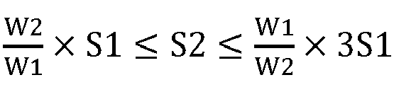
- the first tab and the second tab at least partly protrude from the first regions, where a packaging strength of the first regions is S1, a width of the first regions is W1 in a length direction of the battery cell; the second region is connected to the first regions, a packaging strength of the second region is S2, and a width of the second region is W2 in the length direction of the battery cell.
- S1, W1, S2, and W2 satisfy the following relationship: W 2 W 1 ⁇ S 1 ⁇ S 2 ⁇ W 1 W 2 ⁇ 3 S 1 .
- S1, S2, and W1 are in the following ranges: 0.5N/m ⁇ S1 ⁇ 10N/m, 0.8S1 ⁇ S2 ⁇ 3.4S1, and 1.5mm ⁇ W1 ⁇ 3.0mm.
- the packaging bag includes a first packaging film and a second packaging film, where the first packaging film includes a first fusion layer, and the second packaging film includes a second fusion layer disposed opposite to the first fusion layer, and the first fusion layer and the second fusion layer are sealed together to form the sealing portion and an accommodating space for accommodating the electrode assembly.
- the first fusion layer and the second fusion layer may be hot-pressed sealing material layers.
- the electrode assembly further includes a first adhesive layer opposite to the first fusion layer and a second adhesive layer opposite to the second fusion layer.
- the first tab is disposed between the first adhesive layer and the second adhesive layer, and the first adhesive layer and the second adhesive layer are disposed between the first fusion layer and the second fusion layer to form the first regions where the first tab protrudes from.
- the electrode assembly further includes a third adhesive layer opposite to the first fusion layer and a fourth adhesive layer opposite to the second fusion layer; the second tab is disposed between the third adhesive layer and the fourth adhesive layer, and the third adhesive layer and the fourth adhesive layer are disposed between the first fusion layer and the second fusion layer to form the first regions where the second tab protrudes from.
- the second adhesive layer, the third adhesive layer, the fourth adhesive layer, and the first adhesive layer may have a same structure and material, or certainly, may have different structures and materials.
- the first adhesive layer is a single-layer structure, and a melting point thereof is 100°C to 150°C.
- the first adhesive layer may be a hot-pressed sealing material layer.
- the first adhesive layer is a double-layer structure which includes: a first layer opposite to the first fusion layer, where a melting point of the first layer is 100°C to 170°C; and a second layer opposite to the first tab, where a melting point of the second layer is 105°C to 145°C.
- the first adhesive layer is a three-layer structure which includes: a first layer opposite to the first fusion layer, where a melting point of the first layer is 100°C to 170°C; a second layer opposite to the first tab, where a melting point of the second layer is 100°C to 170°C; and a third layer disposed between the first layer and the second layer, where a melting point of the third layer is 200°C to 300°C.
- the structures of the first adhesive layer are also applicable to the second adhesive layer, the third adhesive layer, and the fourth adhesive layer. This means that in the embodiments, the second adhesive layer, the third adhesive layer, and the fourth adhesive layer may also have any one of the foregoing structures.
- the second packaging film and the first packaging film have a same structure.
- the first packaging film includes the first fusion layer.
- the first fusion layer has a melting point of 105°C to 165°C, and may be made of a hot-pressed sealing material.
- the first packaging film is a three-layer structure which further includes a barrier material layer and a metal layer clamped between the barrier material layer and the first fusion layer.
- the first packaging film is a four-layer structure which further includes two barrier material layers that are stacked and a metal layer clamped between one of the barrier material layers and the first fusion layer.
- the first packaging film is a five-layer structure which includes the first fusion layer, a first bonding layer, a metal layer, a second bonding layer, and a barrier material layer sequentially from the inside outward.
- the first packaging film is a six-layer structure which includes the first fusion layer, a metal layer, a first bonding layer, a first barrier material layer, a second bonding layer, and a second barrier material layer sequentially from the inside outward.
- the structures of the first packaging layer are also applicable to the second packaging layer. This means that in the embodiments, the second packaging layer may also have any one of the foregoing structures.
- the embodiments of this application further provide a battery which includes the battery cell described in any one of the foregoing embodiments.
- the embodiments of this application further provide an electronic device which includes a battery and a housing for accommodating the battery, where the battery includes the battery cell described in any one of the foregoing embodiments.
- the battery cell provided according to this application has the following excellent technical effects:
- Different regions of the sealing portion of the battery cell are obviously different in packaging strength (to be specific, the packaging strength S 1 and width W1 of the first regions where the first tab and the second tab protrude from and the packaging strength S2 and width W2 of the other region (second region) of the sealing portion satisfy the relationship: W 2 W 1 ⁇ S 1 ⁇ S 2 ⁇ W 1 W 2 ⁇ 3 S 1 ), so that impact produced by gas pressure inside the battery cell which swells under high temperature strikes the regions of weaker packaging strength (first regions) of the sealing portion more heavily. As a result, these regions open earlier when they are not able to withstand the heavier gas pressure, allowing heat to dissipate effectively therefrom.
- the tab regions (first regions) and non-tab region (second region) of the sealing portion of the battery cell are designed with non-uniform packaging strength, the regions with weaker packaging strength of the battery cell open earlier under high temperature, so that heat produced by the battery cell can quickly and effectively dissipate by virtue of these regions. It is no doubt that this would make the battery cell less likely to have dangers such as fire and explosion resulting from heat accumulation, thus greatly improving safety performance of the battery cell under high temperature.
- FIG. 1 is a schematic front view of a battery cell according to this application.
- the battery cell includes a packaging bag 1 and an electrode assembly 2.
- the packaging bag 1 may contain an electrolyte (not shown in the figure) in its interior, and accommodates the electrode assembly 2. This means that a part (lower part in the figure) of the electrode assembly 2 is located inside the packaging bag 1 and soaked in the electrolyte, and the other part (upper part in the figure) thereof is located outside the packaging bag 1.
- the electrode assembly 2 includes a first tab 101 and a second tab 102 which protrude from the top of the packaging bag 1(according to the orientation given in FIG.1 ).
- the top of the packaging bag 1 is a sealing portion (which is therefore also called a top seal), and the sealing portion includes:
- the sealing portion (top in FIG. 1 ) of the packaging bag 1 is composed of tab regions (namely, first regions a) where the first tab 101 and the second tab 102 protrude from and the other region (namely, the non-tab region which is the foregoing second region b).
- the tab regions and the non-tab region of the sealing portion of the packaging bag 1 have different packaging strengths.
- a total length of the battery cell is T1.
- a width of the first regions a is W1
- a width of the second region b is W2
- a packaging strength of the first regions a is S1
- a packaging strength of the second region b is S2.
- S1, W1, S2, and W2 satisfy the following relationship: W 2 W 1 ⁇ S 1 ⁇ S 2 ⁇ W 1 W 2 ⁇ 3 S 1 .
- the tab regions a and the non-tab region b of the sealing portion of the battery cell designed based on this relationship have different packaging strengths, and therefore the sealing portion does not have uniform packaging strength in overall.
- the non-tab region b has greater packaging strength than the tab regions a.
- the packaging strength S2 of the non-tab region b is greater than or equal to the packaging strength S1 of the tab regions a, but less than or equal to 3 times the packaging strength S1 of the tab regions a of the top seal.
- the packaging strength S1 of the tab regions a is 0.5N/m ⁇ S1 ⁇ 10N/m
- the packaging strength S2 of the non-tab region b is 1.2S1 ⁇ S2 ⁇ 2.8S1.
- battery cells with the packaging strengths S1 and S2 within such ranges have better safety performance, as their top seals open more easily under high temperature.
- the packaging strength S1 of the tab regions a is 2.0N/m ⁇ S1 ⁇ 8.0N/m
- the packaging strength S2 of the non-tab region is 1.5S1 ⁇ S2 ⁇ 2.5S1.
- the packaging strength S1 of the tab regions a is 2.9N/m ⁇ S1 ⁇ 4.5N/m
- the packaging strength S2 of the non-tab region b is 1.8S1 ⁇ S2 ⁇ 2.2S1.
- the packaging strength S1 of the tab regions a is 3.9N/m
- the packaging strength S2 of the non-tab region (b) is 1.3S1, as in Example 6 given in Table 1, in which case battery cells can 100% pass testing with their top seals open after heating for 60 minutes under 140°C.
- S1 and S2 are within the following numerical ranges: 0.5N/m ⁇ S1 ⁇ 10N/m and 0.8S1 ⁇ S2 ⁇ 3.4S1, and W1 is 1.5mm ⁇ W1 ⁇ 3.0mm.
- a battery cell designed according to such parameter ranges not only helps to make the non-tab region and tab regions of the sealing portion at the cell top have different packaging strengths, but also minimizes loss of energy density of the battery cell.
- FIG. 2 is a schematic top view of the battery cell shown in FIG. 1 .
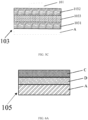
- the packaging bag 1 includes a first packaging film 105 and a second packaging film 105' which are joined to form the packaging bag 1.
- the first packaging film 105 includes a first fusion layer A
- the second packaging film 105' includes a second fusion layer A' disposed opposite to the first fusion layer A, and the first fusion layer A and the second fusion layer A' are sealed together to form the sealing portion and an accommodating space for accommodating the electrode assemblies 1 and 2.
- a melting point of the first fusion layer is 105°C to 165°C.
- the electrode assembly 1 or 2 further includes a first adhesive layer 103 opposite to the first fusion layer A and a second adhesive layer 104 opposite to the second fusion layer A'; the first tab 101 is disposed between the first adhesive layer 103 and the second adhesive layer 104, and the first adhesive layer 103 and the second adhesive layer 104 are disposed between the first fusion layer A and the second fusion layer A' to form one first region a where the first tab 101 protrudes from.
- the electrode assembly 1 or 2 further includes a third adhesive layer 105 opposite to the first fusion layer A and a fourth adhesive layer 106 opposite to the second fusion layer A'; the second tab 102 is disposed between the third adhesive layer 105 and the fourth adhesive layer 106, and the third adhesive layer 105 and the fourth adhesive layer 106 are disposed between the first fusion layer A and the second fusion layer A' to form another first region a where the second tab 102 protrudes from.
- opposite to in this application means that two layers are adjacent and in contact with each other, or even bonded together (for example, two layers are bonded by melting). The same applies below.
- FIG. 3A is a local enlarged view of a position F of the battery cell shown in FIG. 2 , illustrating a local structure of the first region a on the left side of FIG. 2 .
- the region is not open.
- pressure inside the battery cell specifically, inside the packaging bag 1 also increases constantly which impacts the sealing portion (the tab regions a and the non-tab region b) of the battery cell.
- a tab region a with a weaker packaging strength opens earlier in a way shown in FIG. 3B , where the first adhesive layer 103 and the second adhesive layer 104 are pushed apart by pressure to form an opening 100 between them.
- the second adhesive layer 104 and the second fusion layer A' are pushed apart by pressure to form an opening 100 between them as shown in FIG. 3C , or the first adhesive layer 103 and the first fusion layer are pushed apart by pressure to form an opening 100 (symmetrical to the shape shown in FIG. 3C , not shown in the figure).
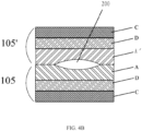
- FIG. 4A is a local enlarged view of a position G of the battery cell shown in FIG. 2 , illustrating a local structure of the second region b (region where no tab protrudes from) of the sealing portion of the battery cell.
- the region is not open.
- the non-tab region b is also likely to open to form an additional heat dissipation hole.
- the non-tab region b is likely to open in a way shown in FIG.
- heat dissipation openings are formed in both the tab region a and the non-tab region b, meaning that a plurality of heat dissipation openings are formed in the sealing portion of the packaging bag of the battery cell. Obviously, this helps to discharge heat of the battery cell as quickly as possible, thus reducing the risk of fire or explosion of the battery cell due to unexpected overheating.
- first adhesive layer the second adhesive layer, the third adhesive layer, and the fourth adhesive layer may have a same structure and material, or certainly, they may have different structures and materials.
- first adhesive layer describes the first adhesive layer as an example.
- the first adhesive layer 103 is a single-layer structure 1031 (for example, a hot-pressed sealing material layer may be made of PP (polypropylene) or PPA (polyphthalamide) or CPP (chlorinated polypropylene) or the like), and a melting point of the first adhesive layer 1031 is 100°C to 150°C.
- a hot-pressed sealing material layer may be made of PP (polypropylene) or PPA (polyphthalamide) or CPP (chlorinated polypropylene) or the like
- a melting point of the first adhesive layer 1031 is 100°C to 150°C.
- Such adhesive layer has a simple structure and is not costly.
- the first adhesive layer 103 is a double-layer structure which includes a first layer 1031 opposite to the first fusion layer A, where a melting point of the first layer 1031 is 100°C to 170°C, and a second layer 1032 opposite to the first tab 101, where a melting point of the second layer 1032 is 105°C to 145°C.
- the first layer 1031 and the second layer 1032 are made of different materials, for example, the first layer 1031 is made of polypropylene, and the second layer 1032 is made of polyethylene propylene copolymer.
- a double-layer tab adhesive is more beneficial to safety performance of a battery cell under high temperature.
- the second layer 1032 of the double-layer tab adhesive has a lower temperature, and when the battery cell swells under high temperature, an interface between the second layer 1032 of the tab adhesive in the top seal tab region and the first tab 101 is weaker and easier to open than that of a battery cell with a single adhesive layer, thus being beneficial to heat dissipation.
- the first adhesive layer 103 includes a first layer 1031 opposite to the first fusion layer A, where a melting point of the first layer 1031 is 100°C to 170°C, a second layer 1032 opposite to the first tab 101, where a melting point of the second layer 1032 is 105°C to 145°C, and a third layer 1033 disposed between the first layer 1031 and the second layer 1032, where a melting point of the third layer 1033 is 200°C to 300°C.
- the first layer 1031 and the second layer 1032 may be made of a same material or different materials.
- the third layer 1033 differs from the first layer 1031 and the second layer 1032 in terms of material, and therefore has a higher melting point than them. Therefore, when the battery cell is to have a heat dissipation opening under high temperature, the second layer 1032 and the first tab 101, or the first layer 1031 and the first fusion layer A, become apart earlier than the third layer 1033 is apart from the first layer 1031 and the second layer 1032.
- a three-layer adhesive structure has higher mechanical strength and hardness because of a higher melting point of an intermediate layer. After hot-pressing packaging, such tab adhesive is less deformed so that the battery cell has better uniformity.
- battery cells with a three-layer adhesive structure have longer service life.
- the second adhesive layer, the third adhesive layer, and the fourth adhesive layer may also have any one of the foregoing structures.
- the first adhesive layer is a single-layer structure
- the second adhesive layer may be a single-layer, double-layer or three-layer structure.
- the third adhesive layer and the fourth adhesive layer may also have different structures.
- the second packaging film 105' may have the same structure as the first packaging film 105. Therefore, the following describes the first packaging film 105 as an example.
- FIGS. 6A-6D are cross-sectional views of the first packaging film 105 in different embodiments.
- the first packaging film 105 is a three-layer structure which includes the first fusion layer A, a barrier material layer C, and a metal layer D clamped between the barrier material layer C and the first fusion layer A.
- the first fusion layer A implements fusion bonding with the tab adhesive; the metal layer D give the packaging film 105 some rigidity; and the barrier material layer C is used to protect the metal layer D and may be made of an insulating material. Relatively, the packaging film with such structure is less costly.
- the first packaging film 105 is a four-layer structure which includes the first fusion layer A, two barrier material layers that are stacked, and a metal layer D clamped between one of the barrier material layers C and the first fusion layer A. These layers have functions similar to those in the preceding embodiment, and the two barrier material layers C may be made of different materials.
- the first packaging film 105 is a five-layer structure which includes the first fusion layer A, a first bonding layer E1, a metal layer D, a second bonding layer E2, and a barrier material layer C sequentially from the inside outward.
- the first fusion layer A and the metal layer D are bonded by the first bonding layer E1
- the metal layer D and the barrier material layer C are bonded by the second bonding layer E1.
- As two bonding layers are provided all the layers of the first packaging film 105 are firmly bonded together. Therefore, the first packaging film 105 has good rigidity and sealing performance in overall.
- the first packaging film 105 is a six-layer structure which includes the first fusion layer A, a metal layer D, a first bonding layer E1, a first barrier material layer C, a second bonding layer E2, and a second barrier material layer C sequentially from the inside outward.
- two barrier material layers and two bonding layers are provided, further improving overall sealing performance of the packaging film 105.
- a battery provided according to this application contains the foregoing battery cell.
- the battery cell can reduce risks of fire or explosion during charging of the battery, thereby improving safety performance of the battery.
- An electronic device provided according to this application may include a battery and a housing for accommodating the battery, where the battery includes the foregoing battery cell.
- the battery containing such battery cell can improve safety performance of the electronic device in overall, without affecting its quick-charge performance and other performance.
- Comparative Example 2 1.1 1.9 4.7 160 160 162 515 pass 3/5 pass 0/5 pass After heating for 60 min under 130°C, the battery cells swelled but their top seals did not open. After heating for 60 min under 140°C, approximately 50% of the battery cells caught fire and failed and their top seals did not open.
- Example 1 2.1 2.9 7.0 138 138 162 5/5 pass 5/5 pass 115 pass Compared with the comparative examples, the battery cells 100% passed the test with their top seals open after heating for 60 min under 140°C.
- Example 2 1.8 3.3 5.1 138 138 163 5/5 pass 5/5 pass 0/5 pass Compared with the comparative examples, the battery cells 100% passed the test with their top seals open after heating for 60 min under 140°C.
- Example 3 2.0 3.1 6.7 138 138 161 5/5 pass 5/5 pass 0/5 pass Compared with the comparative examples, the battery cells 100% passed the test with their top seals open after heating for 60 min under 140°C.
- Example 4 1.7 3.5 5.5 139 138 162 5/5 pass 5/5 pass 0/5 pass Compared with the comparative examples, the battery cells 100% passed the test with their top seals open after heating for 60 min under 140°C.
- Example 5 1.7 2.7 5.7 138 138 162 5/5 pass 5/5 pass 0/5 pass Compared with the comparative examples, the battery cells 100% passed the test with their top seals open after heating for 60 min under 140°C.
- Example 6 1.5 3.9 5.1 138 140 162 5/5 pass 5/5 pass 0/5 pass Compared with the comparative examples, the battery cells 100% passed the test with their top seals open after heating for 60 min under 140°C.
- Example 7 2.2 4.2 7.3 135 134 163 5/5 pass 5/5 pass 2/5 pass Compared with the comparative examples, the battery cells 100% passed the test with their top seals open after heating for 60 min under 140°C; and some of the battery cells passed the test with their top seals open after heating for 60 min under 150°C.
- Example 8 2.5 3.5 8.2 138 135 162 5/5 pass 5/5 pass 4/5 pass Compared with the comparative examples, the battery cells 100% passed the test with their top seals open after heating for 60 min under 140°C; and some of the battery cells passed the test with their top seals open after heating for 60 min under 150°C.
- W2 W1
- the value of W1 is measured through CT (Computed Tomography), and the unit of which is mm
- S1 is measured by Tensile Testing Machine, the unit of which is N/m, and the same as S2
- the melting point is measured by DSC (Differential Scanning Calorimeter), the unit of which is °C.
- DSC Densential Scanning Calorimeter
- spatial relation terms such as “under”, “below”, “lower part”, “above”, “upper part”, “lower part”, “left side”, “right side”, and the like are used in this application to describe the relationship between one component or feature and another component or feature as illustrated in the figures.
- the spatial relation terms are intended to cover different orientations of devices in use or operation.
- the devices can be oriented in other ways (rotated by 90 degrees or in other orientations), and spatial relation descriptors used in this application can also be explained accordingly.
- ⁇ hen o ⁇ e component is referred to as being “connected” or “coupled” to another component, it may be connected or coupled to the another component directly or via an intermediate component.
- the term "approximately” generally means being within ⁇ 10%, ⁇ 5%, ⁇ 1% or ⁇ 0.5% of a given value or range.
- a range may be from one endpoint to another endpoint or between two endpoints. Unless otherwise specified, all ranges disclosed in this application are inclusive of endpoints.
Landscapes
- Chemical & Material Sciences (AREA)
- Chemical Kinetics & Catalysis (AREA)
- Electrochemistry (AREA)
- General Chemical & Material Sciences (AREA)
- Sealing Battery Cases Or Jackets (AREA)
Abstract
Description
- This application relates to an energy storage apparatus, and in particular, to a battery cell, a battery containing such battery cell, and an electronic device containing such battery.
- As battery cells have constantly higher energy density and service voltage, they are likely to reach increasingly high temperature in charging. With continued temperature rise, safety performance of the cells is gradually degraded. Specifically, battery cells are likely to produce unexpected heat under extremely high temperature, and such unexpected heat may possibly give rise to fire, explosion, and other incidents.
- In the prior art, to avoid production of a large amount of heat, a usual practice is to replace the cathode material, anode material, and electrolyte (for example, with materials of better thermal stability). However, material replacement may not only increase costs but also impair other performance of the battery cells. For example, although cathode and anode materials of better thermal stability improve safety performance of the battery cells, they are likely to reduce energy density of the battery cells and impair their quick-charge performance.
- Therefore, it is an important subject to be studied how safety performance under high temperature can be improved for battery cells without affecting their other performance, especially how heat dissipation can be improved for battery cells during charging.
- This application is intended to resolve at least one of the technical problems in the prior art, and provides a battery cell with good heat dissipation and high safety performance under high temperature. This application further provides a battery containing such battery cell and an electronic device containing such battery.
- The battery cell provided according to embodiments of this application includes an electrode assembly and a packaging bag accommodating the electrode assembly, where the packaging bag includes a sealing portion, and the electrode assembly includes a first tab and a second tab. The sealing portion includes first regions and a second region. The first tab and the second tab at least partly protrude from the first regions, where a packaging strength of the first regions is S1, a width of the first regions is W1 in a length direction of the battery cell; the second region is connected to the first regions, a packaging strength of the second region is S2, and a width of the second region is W2 in the length direction of the battery cell. S1, W1, S2, and W2 satisfy the following relationship:
- Preferably, S1, S2, and W1 are in the following ranges: 0.5N/m<S1<10N/m, 0.8S1≤S2≤3.4S1, and 1.5mm<W1<3.0mm.
- In an embodiment of this application, the packaging bag includes a first packaging film and a second packaging film, where the first packaging film includes a first fusion layer, and the second packaging film includes a second fusion layer disposed opposite to the first fusion layer, and the first fusion layer and the second fusion layer are sealed together to form the sealing portion and an accommodating space for accommodating the electrode assembly. The first fusion layer and the second fusion layer may be hot-pressed sealing material layers.
- In the foregoing embodiment of this application, the electrode assembly further includes a first adhesive layer opposite to the first fusion layer and a second adhesive layer opposite to the second fusion layer. The first tab is disposed between the first adhesive layer and the second adhesive layer, and the first adhesive layer and the second adhesive layer are disposed between the first fusion layer and the second fusion layer to form the first regions where the first tab protrudes from.
- In addition, in the foregoing embodiment of this application, the electrode assembly further includes a third adhesive layer opposite to the first fusion layer and a fourth adhesive layer opposite to the second fusion layer; the second tab is disposed between the third adhesive layer and the fourth adhesive layer, and the third adhesive layer and the fourth adhesive layer are disposed between the first fusion layer and the second fusion layer to form the first regions where the second tab protrudes from.
- In the embodiments of this application, the second adhesive layer, the third adhesive layer, the fourth adhesive layer, and the first adhesive layer may have a same structure and material, or certainly, may have different structures and materials. The following describes the first adhesive layer as an example.
- In an embodiment, the first adhesive layer is a single-layer structure, and a melting point thereof is 100°C to 150°C. For example, the first adhesive layer may be a hot-pressed sealing material layer.
- In another embodiment, the first adhesive layer is a double-layer structure which includes: a first layer opposite to the first fusion layer, where a melting point of the first layer is 100°C to 170°C; and a second layer opposite to the first tab, where a melting point of the second layer is 105°C to 145°C.
- In a still another embodiment, the first adhesive layer is a three-layer structure which includes: a first layer opposite to the first fusion layer, where a melting point of the first layer is 100°C to 170°C; a second layer opposite to the first tab, where a melting point of the second layer is 100°C to 170°C; and a third layer disposed between the first layer and the second layer, where a melting point of the third layer is 200°C to 300°C.
- The structures of the first adhesive layer are also applicable to the second adhesive layer, the third adhesive layer, and the fourth adhesive layer. This means that in the embodiments, the second adhesive layer, the third adhesive layer, and the fourth adhesive layer may also have any one of the foregoing structures.
- In the embodiments of this application, the second packaging film and the first packaging film have a same structure. The following describes the first packaging film as an example.
- As previously mentioned, the first packaging film includes the first fusion layer. In the embodiments of this application, the first fusion layer has a melting point of 105°C to 165°C, and may be made of a hot-pressed sealing material.
- In an embodiment of this application, the first packaging film is a three-layer structure which further includes a barrier material layer and a metal layer clamped between the barrier material layer and the first fusion layer.
- In another embodiment of this application, the first packaging film is a four-layer structure which further includes two barrier material layers that are stacked and a metal layer clamped between one of the barrier material layers and the first fusion layer.
- In still another embodiment of this application, the first packaging film is a five-layer structure which includes the first fusion layer, a first bonding layer, a metal layer, a second bonding layer, and a barrier material layer sequentially from the inside outward.
- In yet another embodiment of this application, the first packaging film is a six-layer structure which includes the first fusion layer, a metal layer, a first bonding layer, a first barrier material layer, a second bonding layer, and a second barrier material layer sequentially from the inside outward.
- The structures of the first packaging layer are also applicable to the second packaging layer. This means that in the embodiments, the second packaging layer may also have any one of the foregoing structures.
- The embodiments of this application further provide a battery which includes the battery cell described in any one of the foregoing embodiments.
- In addition, the embodiments of this application further provide an electronic device which includes a battery and a housing for accommodating the battery, where the battery includes the battery cell described in any one of the foregoing embodiments.
- Compared with the prior art, the battery cell provided according to this application has the following excellent technical effects:
- Different regions of the sealing portion of the battery cell are obviously different in packaging strength (to be specific, the
packaging strength S 1 and width W1 of the first regions where the first tab and the second tab protrude from and the packaging strength S2 and width W2 of the other region (second region) of the sealing portion satisfy the relationship:
- To help better understand specific embodiments and excellent technical effects of this application more clearly, the following describes the embodiments of this application in detail with reference to the accompanying drawings.
-
FIG. 1 is a schematic front view of a battery cell according to this application, schematically illustrating a front-view structure of the battery cell; -
FIG. 2 is a schematic top view of the battery cell shown inFIG. 1 , schematically illustrating a top-view cross section structure of the battery cell; -
FIG. 3A is a local enlarged view of a position F of the battery cell shown inFIG. 2 , illustrating a local structure of a first region a on the left side (region where a first tab protrudes from), where the region is not open; -
FIG. 3B also illustrates a local structure of the first region a, which is the same asFIG. 3A except that the region is open in one way (where a first adhesive layer and a second adhesive layer are pushed apart to form an opening); -
FIG. 3C also illustrates a structure of the first region a in an open state, which is the same asFIG. 3B except for a different way of opening (where a second fusion layer and the second adhesive layer are pushed apart to form an opening); -
FIG. 4A is a local enlarged view of a position G of the battery cell shown inFIG. 2 , illustrating a local structure of a second region b (region where no tab protrudes from) of the sealing portion of the battery cell, where the region is not open; -
FIG. 4B also illustrates a local structure of the second region b, which is the same asFIG. 4A except that the region is open in one way (where a first fusion layer A and a second fusion layer A' are pushed apart to form an opening); -
FIG. 4C also illustrates a structure of the second region b in an open state, which is the same asFIG. 4B except for a different way of opening (where the second fusion layer A' is pushed to form an opening at a side close to a metal layer D; -
FIGS. 5A-5C are cross-sectional views of a first adhesive layer, illustrating the first adhesive layer as single-layer, double-layer, and three-layer structures, respectively; and -
FIGS. 6A-6D are cross-sectional views of a first packaging film, illustrating the first packaging film as three-layer, four-layer, five-layer, and six-layer structures, respectively. - The following describes embodiments of this application in detail with reference to the accompanying drawings. The aspects of this application can be more easily understood by reading the descriptions of the following embodiments with reference to the accompanying drawings. It should be noted that these embodiments are merely exemplary, only intended to explain technical solutions of this application rather than to limit it. Persons skilled in the art can make various modifications and replacements based on these embodiments, but all technical solutions obtained by equivalent replacements fall within the protection scope of this application.
-
FIG. 1 is a schematic front view of a battery cell according to this application. - As shown in
FIG. 1 , the battery cell includes apackaging bag 1 and anelectrode assembly 2. Thepackaging bag 1 may contain an electrolyte (not shown in the figure) in its interior, and accommodates theelectrode assembly 2. This means that a part (lower part in the figure) of theelectrode assembly 2 is located inside thepackaging bag 1 and soaked in the electrolyte, and the other part (upper part in the figure) thereof is located outside thepackaging bag 1. - Specifically, as shown in
FIG. 1 , theelectrode assembly 2 includes afirst tab 101 and asecond tab 102 which protrude from the top of the packaging bag 1(according to the orientation given inFIG.1 ). The top of thepackaging bag 1 is a sealing portion (which is therefore also called a top seal), and the sealing portion includes: - first regions a where the
first tab 101 and thesecond tab 102 at least partly protrude from, which therefore may be understood as tab regions of the sealing portion; and - a second region b transversely connected to the first regions a with no tab protruding therefrom, which therefore may be understood as a non-tab region of the sealing portion.
- In a word, in this application, the sealing portion (top in
FIG. 1 ) of thepackaging bag 1 is composed of tab regions (namely, first regions a) where thefirst tab 101 and thesecond tab 102 protrude from and the other region (namely, the non-tab region which is the foregoing second region b). In this application, the tab regions and the non-tab region of the sealing portion of thepackaging bag 1 have different packaging strengths. - Specifically, as shown in
FIG. 1 , a total length of the battery cell is T1. In a length direction of the battery cell, a width of the first regions a is W1, a width of the second region b is W2, a packaging strength of the first regions a is S1, and a packaging strength of the second region b is S2. Then, S1, W1, S2, and W2 satisfy the following relationship:
- The tab regions a and the non-tab region b of the sealing portion of the battery cell designed based on this relationship have different packaging strengths, and therefore the sealing portion does not have uniform packaging strength in overall. To be specific, the non-tab region b has greater packaging strength than the tab regions a. With such structural parameters, when the battery cell interior swells under high temperature, a region with weaker packaging strength (tab region a) opens earlier than a region with greater packaging strength (non-tab region b) under pneumatic impact of gases inside the battery cell, allowing heat to discharge as quickly as possible from the earlier opening, which greatly improves safety performance of the battery cell under high temperature and reduces the probability of fire, explosion, and other dangers resulting from heat accumulation in the battery cell.
- In the embodiment shown in
FIG. 1 , W1=W2. Then, the foregoing relationship is S1≤S2≤3S1. In other words, when the tab regions a and the non-tab region b have equal width, the packaging strength S2 of the non-tab region b is greater than or equal to the packaging strength S1 of the tab regions a, but less than or equal to 3 times the packaging strength S1 of the tab regions a of the top seal. In practice, the packaging strengths S1 and S2 of the tab regions a and the non-tab region b can be determined according to the battery cell size, tabs, tab adhesive (the "adhesive layer" described later), and many other factors. For example, optionally 1.2S1≤S2≤2.8S1, 1.5S1≤S2≤2.5S1, 1.8S1≤S2≤2.2S1, or S2=1.3S1 (detailed in the experimental data given later (Table 1)). - For example, in a specific example, the packaging strength S1 of the tab regions a is 0.5N/m<S1<10N/m, and the packaging strength S2 of the non-tab region b is 1.2S1≤S2≤2.8S1. According to testing, battery cells with the packaging strengths S1 and S2 within such ranges have better safety performance, as their top seals open more easily under high temperature. More preferably, the packaging strength S1 of the tab regions a is 2.0N/m<S1<8.0N/m, and the packaging strength S2 of the non-tab region is 1.5S1≤S2≤2.5S1. For example, in Example 1 given in Table 1, S1=2.9 and S2=7.0. Therefore, S2≈2.4S1, in which case battery cells can 100% pass testing with their top seals open after heating for 60 minutes under 140°C. In another example, the packaging strength S1 of the tab regions a is 2.9N/m<S1<4.5N/m, and the packaging strength S2 of the non-tab region b is 1.8S1≤S2≤2.2S1. For example, in Example 3 given in Table 3, S1=3.3 and S2=5.1. Therefore, S2≈2.16S1, in which case battery cells can 100% pass testing with their top seals open after heating for 60 minutes under 140°C. In yet another example, the packaging strength S1 of the tab regions a is 3.9N/m, and the packaging strength S2 of the non-tab region (b) is 1.3S1, as in Example 6 given in Table 1, in which case battery cells can 100% pass testing with their top seals open after heating for 60 minutes under 140°C.
- In a preferred embodiment of this application, S1 and S2 are within the following numerical ranges: 0.5N/m<S1<10N/m and 0.8S1≤S2≤3.4S1, and W1 is 1.5mm<W1<3.0mm. A battery cell designed according to such parameter ranges not only helps to make the non-tab region and tab regions of the sealing portion at the cell top have different packaging strengths, but also minimizes loss of energy density of the battery cell.
- Referring to
FIG. 2, FIG. 2 is a schematic top view of the battery cell shown inFIG. 1 . As shown in the figure, thepackaging bag 1 includes afirst packaging film 105 and a second packaging film 105' which are joined to form thepackaging bag 1. As shown in the figure, thefirst packaging film 105 includes a first fusion layer A, and the second packaging film 105' includes a second fusion layer A' disposed opposite to the first fusion layer A, and the first fusion layer A and the second fusion layer A' are sealed together to form the sealing portion and an accommodating space for accommodating theelectrode assemblies - As shown in
FIG. 2 , theelectrode assembly adhesive layer 103 opposite to the first fusion layer A and a secondadhesive layer 104 opposite to the second fusion layer A'; thefirst tab 101 is disposed between the firstadhesive layer 103 and the secondadhesive layer 104, and the firstadhesive layer 103 and the secondadhesive layer 104 are disposed between the first fusion layer A and the second fusion layer A' to form one first region a where thefirst tab 101 protrudes from. - Similarly, referring to the right side of
FIG. 2 , theelectrode assembly adhesive layer 105 opposite to the first fusion layer A and a fourthadhesive layer 106 opposite to the second fusion layer A'; thesecond tab 102 is disposed between the thirdadhesive layer 105 and the fourthadhesive layer 106, and the thirdadhesive layer 105 and the fourthadhesive layer 106 are disposed between the first fusion layer A and the second fusion layer A' to form another first region a where thesecond tab 102 protrudes from. - According to the accompanying drawings, "opposite to" in this application means that two layers are adjacent and in contact with each other, or even bonded together (for example, two layers are bonded by melting). The same applies below.
- Referring to
FIG. 3A, FIG. 3A is a local enlarged view of a position F of the battery cell shown inFIG. 2 , illustrating a local structure of the first region a on the left side ofFIG. 2 . As shown in the figure, the region is not open. When the battery cell is being charged, its temperature rises with the charging, and pressure inside the battery cell (specifically, inside the packaging bag 1) also increases constantly which impacts the sealing portion (the tab regions a and the non-tab region b) of the battery cell. Under the action of this pressure, a tab region a with a weaker packaging strength opens earlier in a way shown inFIG. 3B , where the firstadhesive layer 103 and the secondadhesive layer 104 are pushed apart by pressure to form anopening 100 between them. Alternatively, the secondadhesive layer 104 and the second fusion layer A' are pushed apart by pressure to form anopening 100 between them as shown inFIG. 3C , or the firstadhesive layer 103 and the first fusion layer are pushed apart by pressure to form an opening 100 (symmetrical to the shape shown inFIG. 3C , not shown in the figure). - Referring to
FIG. 4A, FIG. 4A is a local enlarged view of a position G of the battery cell shown inFIG. 2 , illustrating a local structure of the second region b (region where no tab protrudes from) of the sealing portion of the battery cell. As shown inFIG. 4A , the region is not open. When the battery cell is being charged, after the tab region a opens due to high temperature of the battery cell, the continued temperature rise of the battery cell makes the opening of the tab region a insufficient to effectively dissipate heat. In this case, the non-tab region b is also likely to open to form an additional heat dissipation hole. For example, the non-tab region b is likely to open in a way shown inFIG. 4B , where the first fusion layer A and the second fusion layer A' are pushed apart by pressure to form anopening 200, or in a way shown inFIG. 4C , where the second fusion layer A' is pushed by pressure to form anopening 200 at a side close to a metal layer D (detailed below). In this case, heat dissipation openings are formed in both the tab region a and the non-tab region b, meaning that a plurality of heat dissipation openings are formed in the sealing portion of the packaging bag of the battery cell. Obviously, this helps to discharge heat of the battery cell as quickly as possible, thus reducing the risk of fire or explosion of the battery cell due to unexpected overheating. - The following describes structures of the adhesive layers of the tab in detail. In this application, the first adhesive layer, the second adhesive layer, the third adhesive layer, and the fourth adhesive layer may have a same structure and material, or certainly, they may have different structures and materials. The following describes the first adhesive layer as an example.
- Referring to
FIG. 5A , in an embodiment of this application, the firstadhesive layer 103 is a single-layer structure 1031 (for example, a hot-pressed sealing material layer may be made of PP (polypropylene) or PPA (polyphthalamide) or CPP (chlorinated polypropylene) or the like), and a melting point of thefirst adhesive layer 1031 is 100°C to 150°C. Such adhesive layer has a simple structure and is not costly. - Referring to
FIG. 5B , in another embodiment of this application, the firstadhesive layer 103 is a double-layer structure which includes afirst layer 1031 opposite to the first fusion layer A, where a melting point of thefirst layer 1031 is 100°C to 170°C, and asecond layer 1032 opposite to thefirst tab 101, where a melting point of thesecond layer 1032 is 105°C to 145°C. In this case, thefirst layer 1031 and thesecond layer 1032 are made of different materials, for example, thefirst layer 1031 is made of polypropylene, and thesecond layer 1032 is made of polyethylene propylene copolymer. A double-layer tab adhesive is more beneficial to safety performance of a battery cell under high temperature. This is because thesecond layer 1032 of the double-layer tab adhesive has a lower temperature, and when the battery cell swells under high temperature, an interface between thesecond layer 1032 of the tab adhesive in the top seal tab region and thefirst tab 101 is weaker and easier to open than that of a battery cell with a single adhesive layer, thus being beneficial to heat dissipation. - Referring to
FIG. 5C , in yet another embodiment of this application, the firstadhesive layer 103 includes afirst layer 1031 opposite to the first fusion layer A, where a melting point of thefirst layer 1031 is 100°C to 170°C, asecond layer 1032 opposite to thefirst tab 101, where a melting point of thesecond layer 1032 is 105°C to 145°C, and athird layer 1033 disposed between thefirst layer 1031 and thesecond layer 1032, where a melting point of thethird layer 1033 is 200°C to 300°C. In this case, thefirst layer 1031 and thesecond layer 1032 may be made of a same material or different materials. Thethird layer 1033 differs from thefirst layer 1031 and thesecond layer 1032 in terms of material, and therefore has a higher melting point than them. Therefore, when the battery cell is to have a heat dissipation opening under high temperature, thesecond layer 1032 and thefirst tab 101, or thefirst layer 1031 and the first fusion layer A, become apart earlier than thethird layer 1033 is apart from thefirst layer 1031 and thesecond layer 1032. Compared with single-layer and two-layer adhesive structures, a three-layer adhesive structure has higher mechanical strength and hardness because of a higher melting point of an intermediate layer. After hot-pressing packaging, such tab adhesive is less deformed so that the battery cell has better uniformity. In addition, battery cells with a three-layer adhesive structure have longer service life. - In the embodiments, the second adhesive layer, the third adhesive layer, and the fourth adhesive layer may also have any one of the foregoing structures. For example, when the first adhesive layer is a single-layer structure, the second adhesive layer may be a single-layer, double-layer or three-layer structure. Similarly, the third adhesive layer and the fourth adhesive layer may also have different structures.
- In this application, the second packaging film 105' may have the same structure as the
first packaging film 105. Therefore, the following describes thefirst packaging film 105 as an example. - Referring to
FIGS. 6A-6D, FIGS. 6A-6D are cross-sectional views of thefirst packaging film 105 in different embodiments. In the embodiment shown inFIG. 6A , thefirst packaging film 105 is a three-layer structure which includes the first fusion layer A, a barrier material layer C, and a metal layer D clamped between the barrier material layer C and the first fusion layer A. The first fusion layer A implements fusion bonding with the tab adhesive; the metal layer D give thepackaging film 105 some rigidity; and the barrier material layer C is used to protect the metal layer D and may be made of an insulating material. Relatively, the packaging film with such structure is less costly. - In the embodiment shown in
FIG. 6B , thefirst packaging film 105 is a four-layer structure which includes the first fusion layer A, two barrier material layers that are stacked, and a metal layer D clamped between one of the barrier material layers C and the first fusion layer A. These layers have functions similar to those in the preceding embodiment, and the two barrier material layers C may be made of different materials. - In the embodiment shown in
FIG. 6C , thefirst packaging film 105 is a five-layer structure which includes the first fusion layer A, a first bonding layer E1, a metal layer D, a second bonding layer E2, and a barrier material layer C sequentially from the inside outward. The first fusion layer A and the metal layer D are bonded by the first bonding layer E1, and the metal layer D and the barrier material layer C are bonded by the second bonding layer E1. As two bonding layers are provided, all the layers of thefirst packaging film 105 are firmly bonded together. Therefore, thefirst packaging film 105 has good rigidity and sealing performance in overall. - In the embodiment shown in
FIG. 6D , thefirst packaging film 105 is a six-layer structure which includes the first fusion layer A, a metal layer D, a first bonding layer E1, a first barrier material layer C, a second bonding layer E2, and a second barrier material layer C sequentially from the inside outward. In this embodiment, two barrier material layers and two bonding layers are provided, further improving overall sealing performance of thepackaging film 105. - A battery provided according to this application contains the foregoing battery cell. The battery cell can reduce risks of fire or explosion during charging of the battery, thereby improving safety performance of the battery.
- An electronic device provided according to this application may include a battery and a housing for accommodating the battery, where the battery includes the foregoing battery cell. The battery containing such battery cell can improve safety performance of the electronic device in overall, without affecting its quick-charge performance and other performance.
- The following further describes technical effects of the technical solutions of this application with reference to specific experimental data in Table 1.
Table 1 Experimental data and technical effects of Comparative Examples 1-2 and Examples 1-8 No. W1 S1 S2 Melting point of positive-electrode tab adhesive Melting point of negative-electrode tab adhesive Melting point of fusion layer 60 min heating under 130°C 60 min heating under 140°C 60 min heating under 150°C Comparative effect Comparative Example 1 1.2 3.9 4.5 161 160 163 5/5 pass 2/5 pass 0/5 pass After heating for 60 min under 130°C, the battery cells swelled but their top seals did not open. After heating for 60 min under 140°C, approximately 50% of the battery cells caught fire and failed and their top seals did not open. Comparative Example 2 1.1 1.9 4.7 160 160 162 515 pass 3/5 pass 0/5 pass After heating for 60 min under 130°C, the battery cells swelled but their top seals did not open. After heating for 60 min under 140°C, approximately 50% of the battery cells caught fire and failed and their top seals did not open. Example 1 2.1 2.9 7.0 138 138 162 5/5 pass 5/5 pass 115 pass Compared with the comparative examples, the battery cells 100% passed the test with their top seals open after heating for 60 min under 140°C. Example 2 1.8 3.3 5.1 138 138 163 5/5 pass 5/5 pass 0/5 pass Compared with the comparative examples, the battery cells 100% passed the test with their top seals open after heating for 60 min under 140°C. Example 3 2.0 3.1 6.7 138 138 161 5/5 pass 5/5 pass 0/5 pass Compared with the comparative examples, the battery cells 100% passed the test with their top seals open after heating for 60 min under 140°C. Example 4 1.7 3.5 5.5 139 138 162 5/5 pass 5/5 pass 0/5 pass Compared with the comparative examples, the battery cells 100% passed the test with their top seals open after heating for 60 min under 140°C. Example 5 1.7 2.7 5.7 138 138 162 5/5 pass 5/5 pass 0/5 pass Compared with the comparative examples, the battery cells 100% passed the test with their top seals open after heating for 60 min under 140°C. Example 6 1.5 3.9 5.1 138 140 162 5/5 pass 5/5 pass 0/5 pass Compared with the comparative examples, the battery cells 100% passed the test with their top seals open after heating for 60 min under 140°C. Example 7 2.2 4.2 7.3 135 134 163 5/5 pass 5/5 pass 2/5 pass Compared with the comparative examples, the battery cells 100% passed the test with their top seals open after heating for 60 min under 140°C; and some of the battery cells passed the test with their top seals open after heating for 60 min under 150°C. Example 8 2.5 3.5 8.2 138 135 162 5/5 pass 5/5 pass 4/5 pass Compared with the comparative examples, the battery cells 100% passed the test with their top seals open after heating for 60 min under 140°C; and some of the battery cells passed the test with their top seals open after heating for 60 min under 150°C. - In Table1, W2=W1, the value of W1 is measured through CT (Computed Tomography), and the unit of which is mm; S1 is measured by Tensile Testing Machine, the unit of which is N/m, and the same as S2; the melting point is measured by DSC (Differential Scanning Calorimeter), the unit of which is °C. According to Table 1, in Comparative Example 1, after heating for 60 minutes under 130°C, the battery cells swelled as expected but their top seals did not open; and after heating for 60 minutes under 140°C, approximately 50% of the battery cells caught a fire and failed and their top seals did not open. The test failed.
- By contrast, after heating for 60 minutes under 140°C, the battery cells provided in Examples 1 to 8 100% passed the test (to be specific, the top seals of the cells opened, and the battery cells did not catch fire or explode, considered as being not failed). For Examples 7 and 8, after heating for 60 minutes under 150°C, there were still some battery cells passing the test. In Examples 1 to 8, the relationships between S1 and S2 are approximately S2=2.41S1, S2=1.54S1, S2=2.16S1, S2=1.57S1, S2=2.11S1, S2=1.31S1, S2=1.74S1, and S2=2.34S1, respectively. Therefore, the battery cells provided according to this application have greatly improved safety performance under high temperature.
- Finally, in specific design and manufacture of battery cells, the following two aspects may be combined to make a non-tab region and a tab region have different packaging strengths:
- (1) Increase packaging strength of the non-tab region b of the battery cell, for example, by increasing a width W2 of that region. The non-tab region of the battery cell is sealed by fusing two hot-pressed sealing material layers (the above-mentioned "fusion layers") under high temperature, and the packaging strength of the sealed non-tab region is mainly affected by width of the sealing region when packaging equipment and temperature are unchanged. At present, battery cells of conventional consumer secondary batteries have a length T1 in the range of 10mm<T1<200mm, and a top sealing region width in the range 1.5mm<W1<3.0mm, which helps to implement packaging with non-uniform strength and reduces as much loss of energy density as possible.
- (2) Weaken packaging strength of the tab regions a of the battery cell, for example, by using a sealing material with a relatively low melting point. For example, a tab adhesive may be selected from those having a test melting point within 100°C to 170°C or even 105°C to 145°C, provided that this is implemented for one of a positive-electrode tab and a negative-electrode tab. In addition, sealing of the tab region a is to seal the tab and the packaging film together. Therefore, the high-temperature packaging strength of the tab region a can alternatively be weakened by reducing a melting point of the hot-pressed sealing material (the above-mentioned fusion layer) of the packaging film, where a material with a melting point within 105°C to 165°C is preferably used.
- As used in this application, for ease of description, spatial relation terms such as "under", "below", "lower part", "above", "upper part", "lower part", "left side", "right side", and the like are used in this application to describe the relationship between one component or feature and another component or feature as illustrated in the figures. In addition to orientations depicted in the figures, the spatial relation terms are intended to cover different orientations of devices in use or operation. The devices can be oriented in other ways (rotated by 90 degrees or in other orientations), and spatial relation descriptors used in this application can also be explained accordingly. It should be understood that ωhen oνe component is referred to as being "connected" or "coupled" to another component, it may be connected or coupled to the another component directly or via an intermediate component.
- In this application, the term "approximately" generally means being within ±10%, ±5%, ±1% or ±0.5% of a given value or range. In this application, a range may be from one endpoint to another endpoint or between two endpoints. Unless otherwise specified, all ranges disclosed in this application are inclusive of endpoints.
- Features of some embodiments and details of this application have been described above. A person skilled in the art can make various alternations, replacements, and changes, without departing from the spirit and scope of this application. All such equivalent structures fall within the protection of this application.
Claims (10)
- A battery cell, comprising: an electrode assembly and a packaging bag (1) accommodating the electrode assembly; wherein the packaging bag (1) comprises a sealing portion; and the electrode assembly comprises a first tab (101) and a second tab (102); characterized in that, the sealing portion comprises:first regions (a), wherein the first tab (101) and the second tab (102) at least partly protrude from the first regions (a), a packaging strength of the first regions (a) is S 1, and a width of the first regions is W1 in a length direction of the battery cell; anda second region (b) connected to the first regions (a), wherein a packaging strength of the second region (b) is S2, and a width of the second region (b) is W2 in the length direction of the battery cell;wherein S 1, W1, S2, and W2 satisfy the following relationship:

- The battery cell according to claim 1, characterized in that, 0.5N/m<S1<10N/m, 0.8S1≤S2≤3.4S1.
- The battery cell according to claim 1, characterized in that, 1.5mm<Wl<3.0mm.
- The battery cell according to claim 1, characterized in that, the packaging bag (1) comprises a first packaging film (105) and a second packaging film (105'), wherein the first packaging film (105) comprises a first fusion layer (A), and the second packaging film (105') comprises a second fusion layer (A') disposed opposite to the first fusion layer (A), and the first fusion layer (A) and the second fusion layer (A') are sealed together to form the sealing portion and an accommodating space for accommodating the electrode assembly; and
the electrode assembly further comprises a first adhesive layer (103) opposite to the first fusion layer (A) and a second adhesive layer (104) opposite to the second fusion layer (A'); and the first tab (101) is disposed between the first adhesive layer (103) and the second adhesive layer (104), and the first adhesive layer (103) and the second adhesive layer (104) are disposed between the first fusion layer (A) and the second fusion layer (A') to form the first regions (a) where the first tab (101) protrudes from. - The battery cell according to claim 4, characterized in that, the first adhesive layer (103) is a single-layer structure (1031), wherein a melting point of the first adhesive layer (103) is 100°C to 150°C.
- The battery cell according to claim 4, characterized in that, the first adhesive layer (103) comprises:a first layer (1031) opposite to the first fusion layer (A), wherein a melting point of the first layer (1031) is 100°C to 170°C, anda second layer (1032) opposite to the first tab (101), wherein a melting point of the second layer (1032) is 105°C to 145°C.
- The battery cell according to claim 4, characterized in that, the first adhesive layer (103) comprises:a first layer (1031) opposite to the first fusion layer (A), wherein a melting point of the first layer is 100°C to 170°C;a second layer (1032) opposite to the first tab (101), wherein a melting point of the second layer is 105°C to 145°C; anda third layer (1033) disposed between the first layer (1031) and the second layer (1032), wherein a melting point of the third layer (1033) is 200°C to 300°C.
- The battery cell according to claim 4, characterized in that, a melting point of the first fusion layer (A) is 105°C to 165°C.
- A battery, characterized by comprising the battery cell according to any one of claims 1 to 8.
- An electronic device, characterized by comprising a battery and a housing for accommodating the battery, wherein the battery comprises the battery cell according to any one of claims 1 to 8.
Applications Claiming Priority (1)
| Application Number | Priority Date | Filing Date | Title |
|---|---|---|---|
| PCT/CN2020/082540 WO2021196000A1 (en) | 2020-03-31 | 2020-03-31 | Battery cell, battery, and electronic device |
Publications (2)
| Publication Number | Publication Date |
|---|---|
| EP4131586A1 true EP4131586A1 (en) | 2023-02-08 |
| EP4131586A4 EP4131586A4 (en) | 2024-03-13 |
Family
ID=77808737
Family Applications (1)
| Application Number | Title | Priority Date | Filing Date |
|---|---|---|---|
| EP20928459.5A Pending EP4131586A4 (en) | 2020-03-31 | 2020-03-31 | Battery cell, battery, and electronic device |
Country Status (3)
| Country | Link |
|---|---|
| EP (1) | EP4131586A4 (en) |
| CN (1) | CN113454837B (en) |
| WO (1) | WO2021196000A1 (en) |
Families Citing this family (3)
| Publication number | Priority date | Publication date | Assignee | Title |
|---|---|---|---|---|
| WO2023282632A1 (en) * | 2021-07-06 | 2023-01-12 | 주식회사 엘지에너지솔루션 | Battery cell and battery cell manufacturing apparatus for manufacturing same |
| WO2023282631A1 (en) * | 2021-07-06 | 2023-01-12 | 주식회사 엘지에너지솔루션 | Battery cell and battery module comprising same |
| US20240106070A1 (en) * | 2021-07-06 | 2024-03-28 | Lg Energy Solution, Ltd. | Battery Cell And Battery Module Comprising Same |
Family Cites Families (13)
| Publication number | Priority date | Publication date | Assignee | Title |
|---|---|---|---|---|
| KR20030066895A (en) * | 2002-02-05 | 2003-08-14 | 삼성에스디아이 주식회사 | Secondary battery |
| DE102012205002A1 (en) * | 2012-03-28 | 2013-10-02 | Robert Bosch Gmbh | Seal made of an elastomeric multi-component material, housing, battery cell module and motor vehicle |
| JP6055300B2 (en) * | 2012-12-18 | 2016-12-27 | 大倉工業株式会社 | Lead terminal adhesive tape that can prevent the adhesive strength from decreasing due to hydrogen fluoride |
| JP6699105B2 (en) * | 2015-08-04 | 2020-05-27 | 凸版印刷株式会社 | Resin film for terminal, tab using the same, and power storage device |
| EP3182481A1 (en) * | 2015-12-17 | 2017-06-21 | 3M Innovative Properties Company | Pouch bag battery cells |
| CN105591160A (en) * | 2016-01-20 | 2016-05-18 | 山东精工电子科技有限公司 | Method for verifying package reliability of soft-package battery |
| CN108123176A (en) * | 2016-11-27 | 2018-06-05 | 深圳格林德能源有限公司 | A kind of method for verifying polymer Li-ion battery package quality |
| JP2017069218A (en) * | 2016-12-05 | 2017-04-06 | 油化電子株式会社 | Method for manufacturing laminate film for battery outer packaging |
| CN206480713U (en) * | 2017-01-22 | 2017-09-08 | 宁德新能源科技有限公司 | A kind of secondary cell and heater |
| JP2019087336A (en) * | 2017-11-02 | 2019-06-06 | 積水化学工業株式会社 | Secondary battery |
| CN107785617A (en) * | 2017-11-02 | 2018-03-09 | 上海紫江新材料科技有限公司 | A kind of low temperature tab and preparation method thereof |
| CN110391356B (en) * | 2018-04-19 | 2022-11-08 | 宁德新能源科技有限公司 | Battery with a battery cell |
| CN211828842U (en) * | 2020-03-31 | 2020-10-30 | 宁德新能源科技有限公司 | Battery cell, battery and electronic equipment |
-
2020
- 2020-03-31 CN CN202080011261.7A patent/CN113454837B/en active Active
- 2020-03-31 EP EP20928459.5A patent/EP4131586A4/en active Pending
- 2020-03-31 WO PCT/CN2020/082540 patent/WO2021196000A1/en not_active Ceased
Also Published As
| Publication number | Publication date |
|---|---|
| CN113454837A (en) | 2021-09-28 |
| WO2021196000A1 (en) | 2021-10-07 |
| EP4131586A4 (en) | 2024-03-13 |
| CN113454837B (en) | 2023-09-15 |
Similar Documents
| Publication | Publication Date | Title |
|---|---|---|
| US9705112B2 (en) | Secondary battery with advanced safety | |
| KR100496305B1 (en) | Pouched-type lithium secondary battery and the fabrication method thereof | |
| CN101312253B (en) | Bag type secondary battery | |
| JP3730981B2 (en) | Film outer battery and battery pack | |
| CN211828842U (en) | Battery cell, battery and electronic equipment | |
| US20100266881A1 (en) | Battery cell of improved safety | |
| EP3817082B1 (en) | Pouch case and the method of manufacturing the pouch type secondary battery including the same | |
| EP4131586A1 (en) | Battery cell, battery, and electronic device | |
| KR101255171B1 (en) | secondary battery and manufacturing method thereof | |
| JP2003242952A (en) | Rechargeable battery | |
| US7851078B2 (en) | Secondary battery with a shock absorbing portion | |
| EP4362208A1 (en) | Sealed battery | |
| EP4235929A1 (en) | Secondary battery | |
| KR102522701B1 (en) | The Secondary Battery | |
| US20240120580A1 (en) | Pouch-Type Battery and Sealing Device for Pouch-Type Battery | |
| KR101498471B1 (en) | Secondary Battery Empolyed with Battery Case Having Groove | |
| EP4087028A1 (en) | Secondary battery | |
| EP4231428A1 (en) | Secondary battery | |
| KR101488055B1 (en) | Secondary battery having improved safety, and battery pack using the same | |
| KR20180054297A (en) | A pouch for an battery having enhanced sealing performance and a battery comprising the same | |
| JP7525187B2 (en) | Exterior material and battery using the exterior material | |
| KR101450951B1 (en) | Electrode lead for secondary battery with improved safety and secondary battery using the same | |
| KR20240065025A (en) | Secondary battery | |
| US20260128385A1 (en) | Wound electrode assembly | |
| US20240106043A1 (en) | Pouch-Type Secondary Battery |
Legal Events
| Date | Code | Title | Description |
|---|---|---|---|
| STAA | Information on the status of an ep patent application or granted ep patent |
Free format text: STATUS: THE INTERNATIONAL PUBLICATION HAS BEEN MADE |
|
| PUAI | Public reference made under article 153(3) epc to a published international application that has entered the european phase |
Free format text: ORIGINAL CODE: 0009012 |
|
| STAA | Information on the status of an ep patent application or granted ep patent |
Free format text: STATUS: REQUEST FOR EXAMINATION WAS MADE |
|
| 17P | Request for examination filed |
Effective date: 20221031 |
|
| AK | Designated contracting states |
Kind code of ref document: A1 Designated state(s): AL AT BE BG CH CY CZ DE DK EE ES FI FR GB GR HR HU IE IS IT LI LT LU LV MC MK MT NL NO PL PT RO RS SE SI SK SM TR |
|
| DAV | Request for validation of the european patent (deleted) | ||
| DAX | Request for extension of the european patent (deleted) | ||
| REG | Reference to a national code |
Ref country code: DE Ref legal event code: R079 Free format text: PREVIOUS MAIN CLASS: H01M0050100000 Ipc: H01M0050105000 |
|
| A4 | Supplementary search report drawn up and despatched |
Effective date: 20240212 |
|
| RIC1 | Information provided on ipc code assigned before grant |
Ipc: H01M 50/383 20210101ALN20240206BHEP Ipc: H01M 50/557 20210101ALI20240206BHEP Ipc: H01M 50/55 20210101ALI20240206BHEP Ipc: H01M 50/198 20210101ALI20240206BHEP Ipc: H01M 50/197 20210101ALI20240206BHEP Ipc: H01M 50/193 20210101ALI20240206BHEP Ipc: H01M 50/186 20210101ALI20240206BHEP Ipc: H01M 50/178 20210101ALI20240206BHEP Ipc: H01M 50/133 20210101ALI20240206BHEP Ipc: H01M 50/131 20210101ALI20240206BHEP Ipc: H01M 50/129 20210101ALI20240206BHEP Ipc: H01M 50/105 20210101AFI20240206BHEP |