EP4131565A1 - Battery pack for electric bicycle and electric bicycle equipped with battery pack - Google Patents
Battery pack for electric bicycle and electric bicycle equipped with battery pack Download PDFInfo
- Publication number
- EP4131565A1 EP4131565A1 EP21779389.2A EP21779389A EP4131565A1 EP 4131565 A1 EP4131565 A1 EP 4131565A1 EP 21779389 A EP21779389 A EP 21779389A EP 4131565 A1 EP4131565 A1 EP 4131565A1
- Authority
- EP
- European Patent Office
- Prior art keywords
- battery
- voltage
- battery pack
- charge
- bicycle
- Prior art date
- Legal status (The legal status is an assumption and is not a legal conclusion. Google has not performed a legal analysis and makes no representation as to the accuracy of the status listed.)
- Pending
Links
Images
Classifications
-
- H—ELECTRICITY
- H02—GENERATION; CONVERSION OR DISTRIBUTION OF ELECTRIC POWER
- H02J—ELECTRIC POWER NETWORKS; CIRCUIT ARRANGEMENTS OR SYSTEMS FOR SUPPLYING OR DISTRIBUTING ELECTRIC POWER; SYSTEMS FOR STORING ELECTRIC ENERGY
- H02J7/00—Circuit arrangements for charging or discharging batteries or for supplying loads from batteries
- H02J7/60—Circuit arrangements for charging or discharging batteries or for supplying loads from batteries including safety or protection arrangements
- H02J7/663—Circuit arrangements for charging or discharging batteries or for supplying loads from batteries including safety or protection arrangements using battery or load disconnect circuits
-
- B—PERFORMING OPERATIONS; TRANSPORTING
- B60—VEHICLES IN GENERAL
- B60L—PROPULSION OF ELECTRICALLY-PROPELLED VEHICLES; SUPPLYING ELECTRIC POWER FOR AUXILIARY EQUIPMENT OF ELECTRICALLY-PROPELLED VEHICLES; ELECTRODYNAMIC BRAKE SYSTEMS FOR VEHICLES IN GENERAL; MAGNETIC SUSPENSION OR LEVITATION FOR VEHICLES; MONITORING OPERATING VARIABLES OF ELECTRICALLY-PROPELLED VEHICLES; ELECTRIC SAFETY DEVICES FOR ELECTRICALLY-PROPELLED VEHICLES
- B60L53/00—Methods of charging batteries, specially adapted for electric vehicles; Charging stations or on-board charging equipment therefor; Exchange of energy storage elements in electric vehicles
- B60L53/20—Methods of charging batteries, specially adapted for electric vehicles; Charging stations or on-board charging equipment therefor; Exchange of energy storage elements in electric vehicles characterised by converters located in the vehicle
-
- B—PERFORMING OPERATIONS; TRANSPORTING
- B60—VEHICLES IN GENERAL
- B60L—PROPULSION OF ELECTRICALLY-PROPELLED VEHICLES; SUPPLYING ELECTRIC POWER FOR AUXILIARY EQUIPMENT OF ELECTRICALLY-PROPELLED VEHICLES; ELECTRODYNAMIC BRAKE SYSTEMS FOR VEHICLES IN GENERAL; MAGNETIC SUSPENSION OR LEVITATION FOR VEHICLES; MONITORING OPERATING VARIABLES OF ELECTRICALLY-PROPELLED VEHICLES; ELECTRIC SAFETY DEVICES FOR ELECTRICALLY-PROPELLED VEHICLES
- B60L58/00—Methods or circuit arrangements for monitoring or controlling batteries or fuel cells, specially adapted for electric vehicles
- B60L58/10—Methods or circuit arrangements for monitoring or controlling batteries or fuel cells, specially adapted for electric vehicles for monitoring or controlling batteries
- B60L58/12—Methods or circuit arrangements for monitoring or controlling batteries or fuel cells, specially adapted for electric vehicles for monitoring or controlling batteries responding to state of charge [SoC]
-
- B—PERFORMING OPERATIONS; TRANSPORTING
- B60—VEHICLES IN GENERAL
- B60L—PROPULSION OF ELECTRICALLY-PROPELLED VEHICLES; SUPPLYING ELECTRIC POWER FOR AUXILIARY EQUIPMENT OF ELECTRICALLY-PROPELLED VEHICLES; ELECTRODYNAMIC BRAKE SYSTEMS FOR VEHICLES IN GENERAL; MAGNETIC SUSPENSION OR LEVITATION FOR VEHICLES; MONITORING OPERATING VARIABLES OF ELECTRICALLY-PROPELLED VEHICLES; ELECTRIC SAFETY DEVICES FOR ELECTRICALLY-PROPELLED VEHICLES
- B60L7/00—Electrodynamic brake systems for vehicles in general
- B60L7/10—Dynamic electric regenerative braking
-
- H—ELECTRICITY
- H01—ELECTRIC ELEMENTS
- H01M—PROCESSES OR MEANS, e.g. BATTERIES, FOR THE DIRECT CONVERSION OF CHEMICAL ENERGY INTO ELECTRICAL ENERGY
- H01M10/00—Secondary cells; Manufacture thereof
- H01M10/42—Methods or arrangements for servicing or maintenance of secondary cells or secondary half-cells
- H01M10/44—Methods for charging or discharging
-
- H—ELECTRICITY
- H02—GENERATION; CONVERSION OR DISTRIBUTION OF ELECTRIC POWER
- H02J—ELECTRIC POWER NETWORKS; CIRCUIT ARRANGEMENTS OR SYSTEMS FOR SUPPLYING OR DISTRIBUTING ELECTRIC POWER; SYSTEMS FOR STORING ELECTRIC ENERGY
- H02J7/00—Circuit arrangements for charging or discharging batteries or for supplying loads from batteries
- H02J7/60—Circuit arrangements for charging or discharging batteries or for supplying loads from batteries including safety or protection arrangements
-
- H—ELECTRICITY
- H02—GENERATION; CONVERSION OR DISTRIBUTION OF ELECTRIC POWER
- H02J—ELECTRIC POWER NETWORKS; CIRCUIT ARRANGEMENTS OR SYSTEMS FOR SUPPLYING OR DISTRIBUTING ELECTRIC POWER; SYSTEMS FOR STORING ELECTRIC ENERGY
- H02J7/00—Circuit arrangements for charging or discharging batteries or for supplying loads from batteries
- H02J7/60—Circuit arrangements for charging or discharging batteries or for supplying loads from batteries including safety or protection arrangements
- H02J7/61—Circuit arrangements for charging or discharging batteries or for supplying loads from batteries including safety or protection arrangements against overcharge
-
- H—ELECTRICITY
- H02—GENERATION; CONVERSION OR DISTRIBUTION OF ELECTRIC POWER
- H02J—ELECTRIC POWER NETWORKS; CIRCUIT ARRANGEMENTS OR SYSTEMS FOR SUPPLYING OR DISTRIBUTING ELECTRIC POWER; SYSTEMS FOR STORING ELECTRIC ENERGY
- H02J7/00—Circuit arrangements for charging or discharging batteries or for supplying loads from batteries
- H02J7/60—Circuit arrangements for charging or discharging batteries or for supplying loads from batteries including safety or protection arrangements
- H02J7/62—Circuit arrangements for charging or discharging batteries or for supplying loads from batteries including safety or protection arrangements against overcurrent
-
- H—ELECTRICITY
- H02—GENERATION; CONVERSION OR DISTRIBUTION OF ELECTRIC POWER
- H02J—ELECTRIC POWER NETWORKS; CIRCUIT ARRANGEMENTS OR SYSTEMS FOR SUPPLYING OR DISTRIBUTING ELECTRIC POWER; SYSTEMS FOR STORING ELECTRIC ENERGY
- H02J7/00—Circuit arrangements for charging or discharging batteries or for supplying loads from batteries
- H02J7/80—Circuit arrangements for charging or discharging batteries or for supplying loads from batteries including monitoring or indicating arrangements
- H02J7/82—Control of state of charge [SOC]
- H02J7/825—Detection of fully charged condition
-
- H—ELECTRICITY
- H02—GENERATION; CONVERSION OR DISTRIBUTION OF ELECTRIC POWER
- H02J—ELECTRIC POWER NETWORKS; CIRCUIT ARRANGEMENTS OR SYSTEMS FOR SUPPLYING OR DISTRIBUTING ELECTRIC POWER; SYSTEMS FOR STORING ELECTRIC ENERGY
- H02J7/00—Circuit arrangements for charging or discharging batteries or for supplying loads from batteries
- H02J7/90—Regulation of charging or discharging current or voltage
- H02J7/933—Regulation of charging or discharging current or voltage the cycle being controlled or terminated in response to electric parameters
-
- H—ELECTRICITY
- H02—GENERATION; CONVERSION OR DISTRIBUTION OF ELECTRIC POWER
- H02J—ELECTRIC POWER NETWORKS; CIRCUIT ARRANGEMENTS OR SYSTEMS FOR SUPPLYING OR DISTRIBUTING ELECTRIC POWER; SYSTEMS FOR STORING ELECTRIC ENERGY
- H02J7/00—Circuit arrangements for charging or discharging batteries or for supplying loads from batteries
- H02J7/90—Regulation of charging or discharging current or voltage
- H02J7/96—Regulation of charging or discharging current or voltage in response to battery voltage
-
- B—PERFORMING OPERATIONS; TRANSPORTING
- B60—VEHICLES IN GENERAL
- B60L—PROPULSION OF ELECTRICALLY-PROPELLED VEHICLES; SUPPLYING ELECTRIC POWER FOR AUXILIARY EQUIPMENT OF ELECTRICALLY-PROPELLED VEHICLES; ELECTRODYNAMIC BRAKE SYSTEMS FOR VEHICLES IN GENERAL; MAGNETIC SUSPENSION OR LEVITATION FOR VEHICLES; MONITORING OPERATING VARIABLES OF ELECTRICALLY-PROPELLED VEHICLES; ELECTRIC SAFETY DEVICES FOR ELECTRICALLY-PROPELLED VEHICLES
- B60L2200/00—Type of vehicles
- B60L2200/12—Bikes
-
- B—PERFORMING OPERATIONS; TRANSPORTING
- B60—VEHICLES IN GENERAL
- B60L—PROPULSION OF ELECTRICALLY-PROPELLED VEHICLES; SUPPLYING ELECTRIC POWER FOR AUXILIARY EQUIPMENT OF ELECTRICALLY-PROPELLED VEHICLES; ELECTRODYNAMIC BRAKE SYSTEMS FOR VEHICLES IN GENERAL; MAGNETIC SUSPENSION OR LEVITATION FOR VEHICLES; MONITORING OPERATING VARIABLES OF ELECTRICALLY-PROPELLED VEHICLES; ELECTRIC SAFETY DEVICES FOR ELECTRICALLY-PROPELLED VEHICLES
- B60L2210/00—Converter types
- B60L2210/30—AC to DC converters
-
- B—PERFORMING OPERATIONS; TRANSPORTING
- B62—LAND VEHICLES FOR TRAVELLING OTHERWISE THAN ON RAILS
- B62M—RIDER PROPULSION OF WHEELED VEHICLES OR SLEDGES; POWERED PROPULSION OF SLEDGES OR SINGLE-TRACK CYCLES; TRANSMISSIONS SPECIALLY ADAPTED FOR SUCH VEHICLES
- B62M6/00—Rider propulsion of wheeled vehicles with additional source of power, e.g. combustion engine or electric motor
- B62M6/40—Rider propelled cycles with auxiliary electric motor
-
- B—PERFORMING OPERATIONS; TRANSPORTING
- B62—LAND VEHICLES FOR TRAVELLING OTHERWISE THAN ON RAILS
- B62M—RIDER PROPULSION OF WHEELED VEHICLES OR SLEDGES; POWERED PROPULSION OF SLEDGES OR SINGLE-TRACK CYCLES; TRANSMISSIONS SPECIALLY ADAPTED FOR SUCH VEHICLES
- B62M6/00—Rider propulsion of wheeled vehicles with additional source of power, e.g. combustion engine or electric motor
- B62M6/80—Accessories, e.g. power sources; Arrangements thereof
- B62M6/90—Batteries
-
- H—ELECTRICITY
- H01—ELECTRIC ELEMENTS
- H01M—PROCESSES OR MEANS, e.g. BATTERIES, FOR THE DIRECT CONVERSION OF CHEMICAL ENERGY INTO ELECTRICAL ENERGY
- H01M10/00—Secondary cells; Manufacture thereof
- H01M10/42—Methods or arrangements for servicing or maintenance of secondary cells or secondary half-cells
- H01M10/425—Structural combination with electronic components, e.g. electronic circuits integrated to the outside of the casing
-
- H—ELECTRICITY
- H01—ELECTRIC ELEMENTS
- H01M—PROCESSES OR MEANS, e.g. BATTERIES, FOR THE DIRECT CONVERSION OF CHEMICAL ENERGY INTO ELECTRICAL ENERGY
- H01M10/00—Secondary cells; Manufacture thereof
- H01M10/42—Methods or arrangements for servicing or maintenance of secondary cells or secondary half-cells
- H01M10/46—Accumulators structurally combined with charging apparatus
-
- H—ELECTRICITY
- H01—ELECTRIC ELEMENTS
- H01M—PROCESSES OR MEANS, e.g. BATTERIES, FOR THE DIRECT CONVERSION OF CHEMICAL ENERGY INTO ELECTRICAL ENERGY
- H01M10/00—Secondary cells; Manufacture thereof
- H01M10/42—Methods or arrangements for servicing or maintenance of secondary cells or secondary half-cells
- H01M10/48—Accumulators combined with arrangements for measuring, testing or indicating the condition of cells, e.g. the level or density of the electrolyte
-
- H—ELECTRICITY
- H01—ELECTRIC ELEMENTS
- H01M—PROCESSES OR MEANS, e.g. BATTERIES, FOR THE DIRECT CONVERSION OF CHEMICAL ENERGY INTO ELECTRICAL ENERGY
- H01M10/00—Secondary cells; Manufacture thereof
- H01M10/42—Methods or arrangements for servicing or maintenance of secondary cells or secondary half-cells
- H01M10/425—Structural combination with electronic components, e.g. electronic circuits integrated to the outside of the casing
- H01M2010/4271—Battery management systems including electronic circuits, e.g. control of current or voltage to keep battery in healthy state, cell balancing
-
- H—ELECTRICITY
- H01—ELECTRIC ELEMENTS
- H01M—PROCESSES OR MEANS, e.g. BATTERIES, FOR THE DIRECT CONVERSION OF CHEMICAL ENERGY INTO ELECTRICAL ENERGY
- H01M2220/00—Batteries for particular applications
- H01M2220/20—Batteries in motive systems, e.g. vehicle, ship, plane
-
- H—ELECTRICITY
- H02—GENERATION; CONVERSION OR DISTRIBUTION OF ELECTRIC POWER
- H02J—ELECTRIC POWER NETWORKS; CIRCUIT ARRANGEMENTS OR SYSTEMS FOR SUPPLYING OR DISTRIBUTING ELECTRIC POWER; SYSTEMS FOR STORING ELECTRIC ENERGY
- H02J2207/00—Details of circuit arrangements for charging or discharging batteries or supplying loads from batteries
- H02J2207/40—Details of circuit arrangements for charging or discharging batteries or supplying loads from batteries adapted for charging from various sources, e.g. AC, DC or multivoltage
-
- H—ELECTRICITY
- H02—GENERATION; CONVERSION OR DISTRIBUTION OF ELECTRIC POWER
- H02J—ELECTRIC POWER NETWORKS; CIRCUIT ARRANGEMENTS OR SYSTEMS FOR SUPPLYING OR DISTRIBUTING ELECTRIC POWER; SYSTEMS FOR STORING ELECTRIC ENERGY
- H02J7/00—Circuit arrangements for charging or discharging batteries or for supplying loads from batteries
- H02J7/14—Circuit arrangements for charging or discharging batteries or for supplying loads from batteries for charging batteries from dynamo-electric generators driven at varying speed, e.g. on vehicle
- H02J7/1415—Circuit arrangements for charging or discharging batteries or for supplying loads from batteries for charging batteries from dynamo-electric generators driven at varying speed, e.g. on vehicle with a generator driven by a prime mover other than the motor of a vehicle
-
- Y—GENERAL TAGGING OF NEW TECHNOLOGICAL DEVELOPMENTS; GENERAL TAGGING OF CROSS-SECTIONAL TECHNOLOGIES SPANNING OVER SEVERAL SECTIONS OF THE IPC; TECHNICAL SUBJECTS COVERED BY FORMER USPC CROSS-REFERENCE ART COLLECTIONS [XRACs] AND DIGESTS
- Y02—TECHNOLOGIES OR APPLICATIONS FOR MITIGATION OR ADAPTATION AGAINST CLIMATE CHANGE
- Y02T—CLIMATE CHANGE MITIGATION TECHNOLOGIES RELATED TO TRANSPORTATION
- Y02T10/00—Road transport of goods or passengers
- Y02T10/60—Other road transportation technologies with climate change mitigation effect
- Y02T10/7072—Electromobility specific charging systems or methods for batteries, ultracapacitors, supercapacitors or double-layer capacitors
Definitions
- the present invention relates to a battery pack configured to supply electric power to a driving motor of an electric bicycle, and an electric bicycle equipped with the battery pack.
- Electric bicycles which are equipped with a driving motor for driving a wheel, supply electric power from a battery to the driving motor so that a rider can drive it easily.
- an electric bicycle has been developed including a circuit for charging a battery pack by regenerative braking during braking (PTL 1).
- the electric bicycle described in PTL 1 allows the battery to be charged while ensuring reserve charging capacity in order to decelerate the bicycle by regenerative braking without causing uncomfortable feeling to the rider.
- the battery that has been charged while leaving the reserve charging capacity can still be charged by regenerative braking until it is fully charged, thereby allowing the bicycle to smoothly travel a long downhill slope, for example, while performing regenerative braking.
- the method of charging the battery while ensuring extra charging capacity has the disadvantage that the travel range offered by the battery is reduced because the battery is not fully charged. Moreover, because the bicycle is used under various travelling conditions, the charging current to the battery from the driving motor may significantly fluctuate, causing the battery to be charged momentarily with a large current. When the battery is charged with a large current, the voltage increases abruptly, causing various kinds of adverse effects on the battery.
- An object of the present invention is to provide an electric bicycle battery pack that can limit a voltage increase due to the charging current from the driving motor to prevent the battery deterioration resulting from the voltage increase and can further ensure sufficient safety, and to provide an electric bicycle that is equipped with the battery pack.
- a battery pack includes a rechargeable battery, a charge FET including a parallel diode connected in series with the battery, and a control circuit configured to control turning on and off of the charge FET.
- the control circuit includes a discriminating circuit configured to detect a bicycle-mounted state and a charger-connected state and a memory configured to store a full charge voltage of the battery.
- the control circuit is configured to, while the discriminating circuit detects the bicycle-mounted state, turn off the charge FET.
- the control circuit is configured to, while the discriminating circuit detects the charger-connected state, stop charging the battery by switching the charge FET to turn off the charge FET upon detecting that a voltage of the battery charged by a charger becomes higher than the full charge voltage.
- a battery pack includes a rechargeable battery, a charge FET including a parallel diode connected in series with the battery, and a control circuit configured to turning on and off of controlling the charge FET.
- the control circuit includes a discriminating circuit configured to detect a bicycle-mounted state and a charger-connected state and a memory configured to store a full charge voltage of the battery and a threshold voltage lower than the full charge voltage.
- the control circuit is configured, while the discriminating circuit detects the bicycle-mounted state, to: turn off the charge FET while a voltage of the battery is higher than the threshold voltage; and turn on the charge FET while the voltage of the battery is lower than the threshold voltage.
- the control circuit is configured, while the discriminating circuit detects the charger-connected state, to stop charging the battery by switching the charge FET to turn off the charge FET upon detecting that the voltage of the battery charged by a charger becomes higher than the full charge voltage.
- a battery pack includes a rechargeable battery, a charge FET including a parallel diode connected in series with the battery, and a control circuit configured to control turning on and off of the charge FET.
- the control circuit includes a discriminating circuit configured to detect a bicycle-mounted state and a charger-connected state and a memory configured to store a full charge voltage of the battery and a threshold current of a load current.
- the control circuit is configured, while the discriminating circuit detects the bicycle-mounted state, to: turn off the charge FET when the load current is smaller than the threshold current; and turn on the charge FET when the load current is larger than the threshold current.
- the control circuit is configured, while the discriminating circuit detects the charger-connected state, to stop charging the battery by switching the charge FET to turn off the charge FET upon detecting that the voltage of the battery charged by a charger is higher than the full charge voltage.
- An electric bicycle includes one of the battery packs and a driving motor connected to the battery pack via a control converter.
- the driving motor configured to supply a charging current to the battery pack during regenerative braking of the bicycle.
- An electric bicycle includes one of the battery packs, a driving motor connected to the battery pack via a control converter, and a regenerative braking power generating mechanism configured to charge the battery pack with an electromotive force of the driving motor.
- the electric bicycle battery packs according to the present invention can limit a voltage increase due to the charging current from the driving motor to prevent the battery deterioration resulting from the voltage increase, and can further ensure sufficient safety.
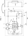
- FIG. 1 is a block diagram of an electric bicycle battery pack according to an exemplary embodiment of the present invention.
- Embodiments of the present invention may be embodied by the following configurations.
- a battery pack for a n electric bicycle includes a rechargeable battery, a charge FET including a parallel diode connected in series with the battery, and a control circuit configured to control turning on and off of the charge FET.
- the control circuit includes a discriminating circuit configured to detect a bicycle-mounted state and a charger-connected state and a memory configured to store a full charge voltage of the battery.
- the control circuit is configured to, while the discriminating circuit detects the bicycle-mounted state, turn off the charge FET.
- the control circuit is configured to, while the discriminating circuit detects the charger-connected state, stop charging the battery by switching the charge FET to turn off the charge FET upon detecting that a voltage of the battery charged by a charger becomes higher than the full charge voltage.
- the above electric bicycle battery pack turns off the charge FET in the bicycle-mounted state of being mounted on the bicycle.
- the charge FET connected to a parallel diode, such as a parasitic diode, causes electric power to be supplied from the battery to the driving motor even when the charge FET is turned off.
- the battery pack prohibits the battery from being charged by the electromotive force of the driving motor while allowing the battery to supply electric power to the driving motor.
- the battery pack is mounted on the bicycle and charged by the electromotive force of the driving motor so that the battery voltage exceeds the full charge voltage, deterioration of the battery is accelerated and safety is lowered.
- the battery pack switches the charge FET to turn off the charge FET while the battery pack is mounted on the bicycle prohibits the battery from being charged by the electromotive force of the driving motor while the battery pack is mounted on the bicycle. Therefore, the battery pack prevents deterioration of a battery resulting from the electromotive force of the driving motor when mounted on the bicycle, thus ensuring sufficient safety.
- a battery pack for an electric bicycle includes a rechargeable battery, a charge FET including a parallel diode connected in series with the battery, and a control circuit configured to turning on and off of controlling the charge FET.
- the control circuit includes a discriminating circuit configured to detect a bicycle-mounted state and a charger-connected state and a memory configured to store a full charge voltage of the battery and a threshold voltage lower than the full charge voltage.
- the control circuit is configured, while the discriminating circuit detects the bicycle-mounted state, to: turn off the charge FET while a voltage of the battery is higher than the threshold voltage; and turn on the charge FET while the voltage of the battery is lower than the threshold voltage.
- the control circuit is configured, while the discriminating circuit detects the charger-connected state, to stop charging the battery by switching the charge FET to turn off the charge FET upon detecting that the voltage of the battery charged by a charger becomes higher than the full charge voltage.
- the above battery pack turns off the charge FET in the bicycle-mounted state in which the battery pack is mounted on the bicycle so as to prohibit the battery from being charged by the electromotive force of the driving motor when the battery voltage is higher than the threshold voltage which is predetermined to be a voltage lower than the full charge voltage. Therefore, although the battery is charged by the electromotive force of the driving motor in the state where the battery voltage is low, the battery voltage does not exceed the full charge voltage in that state, so that battery deterioration can be prevented and sufficient safety can be ensured. When the battery voltage is lower than the threshold voltage, the charge FET is turned on to permit charging by the electromotive force of the driving motor.
- the threshold voltage may be set to a voltage at which the battery is charged by the electromotive force but does not exceed the full charge voltage. Therefore, even when the battery is charged by the electromotive force of the driving motor while the battery voltage is lower than the threshold voltage, the battery voltage does not exceed the full charge voltage, so that battery deterioration is prevented and safety is ensured.
- a battery pack for an electric bicycle includes a rechargeable battery, a charge FET including a parallel diode connected in series with the battery, and a control circuit configured to control turning on and off of the charge FET.
- the control circuit includes a discriminating circuit configured to detect a bicycle-mounted state and a charger-connected state and a memory configured to store a full charge voltage of the battery and a threshold current of a load current.
- the control circuit is configured, while the discriminating circuit detects the bicycle-mounted state, to: turn off the charge FET when the load current is smaller than the threshold current; and turn on the charge FET when the load current is larger than the threshold current.
- the control circuit is configured, while the discriminating circuit detects the charger-connected state, to stop charging the battery by switching the charge FET to turn off the charge FET upon detecting that the voltage of the battery charged by a charger is higher than the full charge voltage.
- the above battery pack turns off the charge FET state when the load current is smaller than the threshold current, but turns on the charge FET when the load current is larger than the threshold current.
- the charge FET connected to a parallel diode allows electric power to be supplied from the battery to the driving motor via the parallel diode when the charge FET is turned off. While the charge FET is turned off and electric power is supplied via the parallel diode, a voltage drop occurs due to the parallel diode. The voltage drop due to the parallel diode is larger than the voltage drop due to the FET which is turned on. An ordinary diode provides the voltage drop of about 0.6 V.
- the internal resistance of the FET which is turned on is significantly small, about several milliohms, so the FET produces a smaller voltage drop than the parallel diode when electric current passes through.
- the parallel diode which causes a larger voltage drop, produces electric power loss increasing proportionally to a current. Therefore, a large current supplied from the battery to the driving motor increases electric power loss in the charge FET which is turned off.
- the above battery pack turns on the charge FET when the load current is larger than the threshold current, so the battery pack may reduce electric power loss due to the charge FET when the large current is supplied from the battery to the driving motor.
- the control circuit includes an A/D converter configured to convert the voltage of the battery into a digital signal.
- the control circuit is configured to calculate the voltage of the battery by processing the digital signal converted by the A/D converter.
- the charge FET is a MOSFET including a parasitic diode as the parallel diode.
- the rechargeable battery is a lithium-ion battery.
- An electric bicycle includes one of the above battery packs and a driving motor connected to the battery pack via a control converter, the driving motor configured to supply a charging current to the battery pack during regenerative braking of the bicycle.
- Electric bicycle battery pack 100 shown in the block diagram of FIG. 1 includes rechargeable battery 1, charge FET 3 including parallel diode 7 connected in series with battery 1, and control circuit 2 configured to control turning on and off of charge FET 3.
- the block diagram of the drawing also shows bicycle 20 to which battery pack 100 is connected, and charger 30 that charges battery pack 100. While being mounted on bicycle 20, battery pack 100 is configured to supply electric power to driving motor 21 that drives bicycle 20. While being connected to charger 30, battery pack 100 is removed from bicycle 20 and connected to charger 30. While being mounted on bicycle 20, battery pack 100 supplies electric power to driving motor 21 to impart a driving force to bicycle 20.
- battery pack 100 shown in FIG. 1 includes discharge FET 4 configured to control discharging of battery 1.
- Charge FET 3 and discharge FET 4 are controlled to be turned on and off by control circuit 2.
- Control circuit 2 includes discriminating circuit 5 and memory 6.
- Discriminating circuit 5 is configured to detect a bicycle-mounted state in which battery pack 100 is mounted on bicycle 20 and a charger-connected state in which battery pack 100 is connected to charger 30.
- Memory 6 is implemented by, for example, a semiconductor memory. Memory 6 is configured to store a full charge voltage for stopping charging upon detecting that battery 1 having a voltage increase is fully charged.
- Each of charge FET 3 and discharge FET 4 is a MOSFET connected to a parasitic diode as parallel diode 7.
- Each of charge FET 3 and discharge FET 4 may be implemented by an FET without a parasitic diode and a high-current diode that is a separate component connected in parallel to the FET, or a large-current diode may be connected in parallel to the parasitic diode.
- a diode exhibiting excellent large-current characteristics is used so that a large current can be supplied from battery 1 to driving motor 21.
- a diode that causes a low voltage drop is particularly suitable.
- Battery pack 100 shown in FIG. 1 includes an N-channel MOS for each of charge FET 3 and discharge FET 4.
- a P-channel FET may be used for each of the charge FET and the discharge FET.
- Discriminating circuit 5 shown in the block diagram of FIG. 1 is connected to bicycle 20 via connecting terminal 12.
- Bicycle-side connecting terminal 22 is connected to ground line 24 via resistor 23.
- connecting terminal 12 is connected to power supply 14 via pull-up resistor 13.
- Discriminating circuit 5 is configured to detect the voltage of connecting terminal 12 so as to discriminate the bicycle-mounted state and the charger-connected state.
- the voltage of connecting terminal 12 becomes lower than the power supply voltage that is divided by pull-up resistor 13 and bicycle-side resistor 23.
- discriminating circuit 5 determines that a state in which the voltage of connecting terminal 12 is lower than the power supply voltage is the bicycle-mounted state, and discriminating circuit 5 determines that a state in which the voltage of connecting terminal 12 is lower than the power supply voltage is the charger-connected state.
- battery pack 100 While battery pack 100 is mounted on bicycle 20, driving motor 21 may serve as a generator to charge battery pack 100 due to, for example, regenerative braking.
- battery pack 100 When battery pack 100 is charged, the voltage increase.
- battery pack 100 When battery pack 100 is charged by the electromotive force of driving motor 21, the voltage of battery pack 100 increases.
- the increased voltage of battery pack 100 higher than a predetermined value deteriorates electrical characteristics, and further it may cause safety hazard.
- lithium-ion batteries are often used suitably for battery pack 100 because they have light weight, small sizes, and capable of high charge/discharge capacity.
- the maximum voltage is set to a voltage ranging from 4.1 V to 4.2 V. However, when lithium-ion batteries are charged to a voltage exceeding the maximum voltage, both electrical characteristics and safety deteriorate.
- control circuit 2 of battery pack 100 shown in FIG. 1 turns off charge FET 3 so as to prevent battery 1 from being charged by the electromotive force of driving motor 21.
- charge FET 3 which is turned off prevents battery 1 from being charged by the electromotive force of driving motor 21, thus preventing battery pack 100 from being charged by the electromotive force from driving motor 21. Accordingly, in this state, the voltage of battery pack 100 does not increase, so that battery pack 100 can prevent battery 1 from deterioration due to the increase of the power supply voltage and prevent battery 1 from causing safety hazard.
- Discharge FET 4 is a switching element that supplies electric power from battery 1 to driving motor 21.
- battery pack 100 As described above supplies electric power from battery 1 to driving motor 21 via parallel diode 7 while charge FET 3 is turned off. Parallel diode 7 is connected so as to pass electric current in a direction reverse to the forward direction of the FET to supply electric current from battery 1 to driving motor 21 with the FET which is turned off.
- battery pack 100 prevents battery 1 from being charged by the electromotive force of driving motor 21 with battery pack 100 being mounted on bicycle 20 while supplying electric power from battery 1 to driving motor 21, so as to prevent deterioration of battery 1 and ensure sufficient safety.
- Control circuit 2 may turn off charge FET 3 whenever battery pack 100 is mounted on bicycle 20. However, control circuit 2 may turn on and off charge FET 3 according to the voltage of the battery to supply a large current from battery 1 to driving motor 21 and reduce electric power loss while preventing deterioration of battery 1 and safety degradation caused by abnormal voltage increase of battery 1.
- memory 6 of control circuit 2 stores a threshold voltage lower than the full charge voltage. The threshold voltage is determined taking into consideration the timing of the time lag of control circuit 2 switching charge FET 3 to turn off charge FET 3.
- Control circuit 2 compares the voltage of battery 1 with the threshold voltage lower than the full charge voltage, and switches charge FET 3 to turn off charge FET 3 when the voltage of battery 1 exceeds the threshold voltage. Therefore, in principle, the voltage of the battery does not exceed the threshold voltage. However, control circuit 2 detects the voltage of the battery, determines whether or not the detected voltage is higher than the threshold voltage, and then switches charge FET 3 to turn off charge FET 3 upon determining that the detected voltage is higher than the threshold voltage. For this reason, a time lag occurs before charge FET 3 is switched to be turned off after the voltage of battery 1 has exceeded the threshold voltage.
- the time lag occurs before an analog signal of the detected battery voltage is converted by an A/D converter into a digital signal, then the converted digital signal is processed to determine whether or not the battery voltage exceeds the threshold voltage, and charge FET 3 is switched to be turned off.
- battery pack 100 calculates the battery voltage by averaging plural digital signals converted by the A/D converter at predetermined sampling periods in order to reduce errors due to noise or the like to detect the battery voltage accurately. Therefore, a time lag occurs in detecting the battery voltage.
- the threshold voltage is determined to be lower than the full charge voltage of battery 1 by a value ranging from 0.1 V to 0.3 V so that battery 1 is not charged by driving motor 21 and the battery voltage does not exceed the threshold voltage during the time lag before charge FET 3 is switched to be turned off after the battery voltage has been detected.
- Control circuit 2 that stores the threshold voltage in memory 6 does not turn off charge FET 3 whenever battery pack 100 is mounted on bicycle 20. While discriminating circuit 5 detects the bicycle-mounted state, control circuit 2 turns off charge FET 3 when the battery voltage is higher than the threshold voltage, but turns on charge FET 3 when the battery voltage is lower than the threshold voltage.
- Charge FET 3 which is turned on supplies electric power from battery 1 to driving motor 21 via the FET which is turned on without passing through parallel diode 7.
- the voltage drop due to parallel diode 7 is large, but the on-resistance of the FET which is turned on is significantly smaller, on the order of milliohms. Accordingly, even when a large current is supplied from battery 1 to driving motor 21, electric power loss caused by charge FET 3 is significantly small.
- Charge FET 3 is switched to be turned on only when the battery voltage is lower than the threshold voltage predetermined to be a voltage lower than the full charge voltage. Therefore, even when charge FET 3 is turned on so that the electromotive force of driving motor 21 charges battery 1 and the battery voltage increases, the battery voltage does not rise to the full charge voltage during the time lag before control circuit 2 detects the increase of the battery voltage and switches charge FET 3 to turn off charge FET 3. This configuration prevents the battery deterioration due to the increased battery voltage exceeding the full charge voltage and also prevents the adverse effect of reduced safety.
- Control circuit 2 switches charge FET 3 to turn on charge FET 3 while the battery voltage is lower than the threshold voltage. However, control circuit 2 may switch charge FET 3 to turn on charge FET only when the load current supplied from battery 1 to driving motor 21 exceeds a threshold current. Control circuit 2 stores a threshold current of the load current in memory 6. While discriminating circuit 5 detects the bicycle-mounted state, control circuit 2 turns off charge FET 3 when the load current is smaller than the threshold current, but turns on charge FET 3 when the load current is larger than the threshold current. Battery pack 100 does not turn on charge FET 3 when the load current supplied from battery 1 to bicycle 20 is smaller than the threshold current, but turns on FET 3 only when a load current larger than the threshold current is supplied from battery 1 to bicycle 20.
- battery pack 100 reduces electric power loss due to charge FET 3 and efficiently supply electric power from battery 1 to driving motor 21 while reliably preventing the voltage of battery 1 from exceeding the full charge voltage.
- battery pack 100 is discharged by supplying electric power from battery 1 to driving motor 21, and battery 1 is not charged by regenerative braking.
- charge FET 3 is switched to be turned on under this condition, battery 1 is prevented from being charged by the electromotive force of driving motor 21 and the battery voltage is prevented from exceeding the full charge voltage, thus ensuring safety of battery 1.By turning on charge FET 3 when the load current is larger than the threshold current, electric power loss due to charge FET 3 is reduced when a large current is supplied from battery 1 to driving motor 21, and also, a large current is prevented from passing through the parallel diode to protect charge FET 3.
- discriminating circuit 5 detects the charger-connected state. When the voltage of the battery charged by charger 30 is lower than the full charge voltage, charge FET 3 is turned on to charge battery 1. When detecting that the voltage of battery 1 being charged is higher than the full charge voltage, charge FET 3 is switched to be turned off to stop charging battery 1.
- Battery pack 100 as described above is mounted on bicycle 20 and is used as a power supply for supplying electric power to driving motor 21 incorporated in bicycle 20.
- Electric bicycle 200 shown in FIG. 1 includes battery pack 100 and control converter 25 connected between battery pack 100 and driving motor 21. Control converter 25 controls electric power supplied from battery pack 100 to driving motor 21.
- Driving motor 21 drives a wheel (not shown) with the electric power supplied from battery pack 100.
- Driving motor 21 is connected to battery pack 100 via control converter 25.
- the electric power supplied from battery pack 100 is controlled by control converter 25 to adjust the rotation torque of the wheel.
- Control converter 25 adjusts the electric power supplied to driving motor 21 based on the speed of the bicycle and the pedal rotation torque produced by the user as parameters.
- Control converter 25 controls the electric power supplied to driving motor 21 so that, for example, a ratio of a pedal rotation torque and the torque at which driving motor 21 rotates the wheel is a predetermined ratio.
- battery pack 100 includes a circuit configured to limit the charging current produced by regenerative braking of the bicycle.
- the present invention is suitably used for a battery pack that supplies electric power to a driving motor of an electric bicycle, particularly for an electric bicycle equipped with a mechanism of charging the battery pack by performing regenerative braking during braking.
Landscapes
- Engineering & Computer Science (AREA)
- Power Engineering (AREA)
- Transportation (AREA)
- Mechanical Engineering (AREA)
- Chemical & Material Sciences (AREA)
- Chemical Kinetics & Catalysis (AREA)
- Manufacturing & Machinery (AREA)
- Electrochemistry (AREA)
- General Chemical & Material Sciences (AREA)
- Sustainable Energy (AREA)
- Sustainable Development (AREA)
- Life Sciences & Earth Sciences (AREA)
- Charge And Discharge Circuits For Batteries Or The Like (AREA)
- Combustion & Propulsion (AREA)
- Secondary Cells (AREA)
Abstract
Description
- The present invention relates to a battery pack configured to supply electric power to a driving motor of an electric bicycle, and an electric bicycle equipped with the battery pack.
- Electric bicycles, which are equipped with a driving motor for driving a wheel, supply electric power from a battery to the driving motor so that a rider can drive it easily. As the electric bicycle of this type, an electric bicycle has been developed including a circuit for charging a battery pack by regenerative braking during braking (PTL 1).
- The electric bicycle described in PTL 1 allows the battery to be charged while ensuring reserve charging capacity in order to decelerate the bicycle by regenerative braking without causing uncomfortable feeling to the rider. The battery that has been charged while leaving the reserve charging capacity can still be charged by regenerative braking until it is fully charged, thereby allowing the bicycle to smoothly travel a long downhill slope, for example, while performing regenerative braking.
- PTL 1:
Japanese Patent Laid-Open Publication No. 2017-103871 - The method of charging the battery while ensuring extra charging capacity has the disadvantage that the travel range offered by the battery is reduced because the battery is not fully charged. Moreover, because the bicycle is used under various travelling conditions, the charging current to the battery from the driving motor may significantly fluctuate, causing the battery to be charged momentarily with a large current. When the battery is charged with a large current, the voltage increases abruptly, causing various kinds of adverse effects on the battery.
- The present invention has been developed in order to solve the foregoing and other problems. An object of the present invention is to provide an electric bicycle battery pack that can limit a voltage increase due to the charging current from the driving motor to prevent the battery deterioration resulting from the voltage increase and can further ensure sufficient safety, and to provide an electric bicycle that is equipped with the battery pack.
- A battery pack according to a first aspect of the invention includes a rechargeable battery, a charge FET including a parallel diode connected in series with the battery, and a control circuit configured to control turning on and off of the charge FET. The control circuit includes a discriminating circuit configured to detect a bicycle-mounted state and a charger-connected state and a memory configured to store a full charge voltage of the battery. The control circuit is configured to, while the discriminating circuit detects the bicycle-mounted state, turn off the charge FET. The control circuit is configured to, while the discriminating circuit detects the charger-connected state, stop charging the battery by switching the charge FET to turn off the charge FET upon detecting that a voltage of the battery charged by a charger becomes higher than the full charge voltage.
- A battery pack according to a second aspect of the invention includes a rechargeable battery, a charge FET including a parallel diode connected in series with the battery, and a control circuit configured to turning on and off of controlling the charge FET. The control circuit includes a discriminating circuit configured to detect a bicycle-mounted state and a charger-connected state and a memory configured to store a full charge voltage of the battery and a threshold voltage lower than the full charge voltage. The control circuit is configured, while the discriminating circuit detects the bicycle-mounted state, to: turn off the charge FET while a voltage of the battery is higher than the threshold voltage; and turn on the charge FET while the voltage of the battery is lower than the threshold voltage. The control circuit is configured, while the discriminating circuit detects the charger-connected state, to stop charging the battery by switching the charge FET to turn off the charge FET upon detecting that the voltage of the battery charged by a charger becomes higher than the full charge voltage.
- A battery pack according to a third aspect of the invention includes a rechargeable battery, a charge FET including a parallel diode connected in series with the battery, and a control circuit configured to control turning on and off of the charge FET. The control circuit includes a discriminating circuit configured to detect a bicycle-mounted state and a charger-connected state and a memory configured to store a full charge voltage of the battery and a threshold current of a load current. The control circuit is configured, while the discriminating circuit detects the bicycle-mounted state, to: turn off the charge FET when the load current is smaller than the threshold current; and turn on the charge FET when the load current is larger than the threshold current. The control circuit is configured, while the discriminating circuit detects the charger-connected state, to stop charging the battery by switching the charge FET to turn off the charge FET upon detecting that the voltage of the battery charged by a charger is higher than the full charge voltage.
- An electric bicycle according to an aspect of the present invention includes one of the battery packs and a driving motor connected to the battery pack via a control converter. The driving motor configured to supply a charging current to the battery pack during regenerative braking of the bicycle.
- An electric bicycle according to another aspect of the present invention includes one of the battery packs, a driving motor connected to the battery pack via a control converter, and a regenerative braking power generating mechanism configured to charge the battery pack with an electromotive force of the driving motor.
- The electric bicycle battery packs according to the present invention can limit a voltage increase due to the charging current from the driving motor to prevent the battery deterioration resulting from the voltage increase, and can further ensure sufficient safety.
-
FIG. 1 is a block diagram of an electric bicycle battery pack according to an exemplary embodiment of the present invention. - Embodiments of the present invention may be embodied by the following configurations.
- A battery pack for a n electric bicycle according to a first exemplary aspect of the present invention includes a rechargeable battery, a charge FET including a parallel diode connected in series with the battery, and a control circuit configured to control turning on and off of the charge FET. The control circuit includes a discriminating circuit configured to detect a bicycle-mounted state and a charger-connected state and a memory configured to store a full charge voltage of the battery. The control circuit is configured to, while the discriminating circuit detects the bicycle-mounted state, turn off the charge FET. The control circuit is configured to, while the discriminating circuit detects the charger-connected state, stop charging the battery by switching the charge FET to turn off the charge FET upon detecting that a voltage of the battery charged by a charger becomes higher than the full charge voltage.
- The above electric bicycle battery pack turns off the charge FET in the bicycle-mounted state of being mounted on the bicycle. The charge FET connected to a parallel diode, such as a parasitic diode, causes electric power to be supplied from the battery to the driving motor even when the charge FET is turned off. While the battery pack is mounted on the bicycle, the battery pack prohibits the battery from being charged by the electromotive force of the driving motor while allowing the battery to supply electric power to the driving motor. When the battery pack is mounted on the bicycle and charged by the electromotive force of the driving motor so that the battery voltage exceeds the full charge voltage, deterioration of the battery is accelerated and safety is lowered. The battery pack switches the charge FET to turn off the charge FET while the battery pack is mounted on the bicycle prohibits the battery from being charged by the electromotive force of the driving motor while the battery pack is mounted on the bicycle. Therefore, the battery pack prevents deterioration of a battery resulting from the electromotive force of the driving motor when mounted on the bicycle, thus ensuring sufficient safety.
- A battery pack for an electric bicycle according to a second exemplary aspect of the present invention includes a rechargeable battery, a charge FET including a parallel diode connected in series with the battery, and a control circuit configured to turning on and off of controlling the charge FET. The control circuit includes a discriminating circuit configured to detect a bicycle-mounted state and a charger-connected state and a memory configured to store a full charge voltage of the battery and a threshold voltage lower than the full charge voltage. The control circuit is configured, while the discriminating circuit detects the bicycle-mounted state, to: turn off the charge FET while a voltage of the battery is higher than the threshold voltage; and turn on the charge FET while the voltage of the battery is lower than the threshold voltage. The control circuit is configured, while the discriminating circuit detects the charger-connected state, to stop charging the battery by switching the charge FET to turn off the charge FET upon detecting that the voltage of the battery charged by a charger becomes higher than the full charge voltage.
- The above battery pack turns off the charge FET in the bicycle-mounted state in which the battery pack is mounted on the bicycle so as to prohibit the battery from being charged by the electromotive force of the driving motor when the battery voltage is higher than the threshold voltage which is predetermined to be a voltage lower than the full charge voltage. Therefore, although the battery is charged by the electromotive force of the driving motor in the state where the battery voltage is low, the battery voltage does not exceed the full charge voltage in that state, so that battery deterioration can be prevented and sufficient safety can be ensured. When the battery voltage is lower than the threshold voltage, the charge FET is turned on to permit charging by the electromotive force of the driving motor. However, the threshold voltage may be set to a voltage at which the battery is charged by the electromotive force but does not exceed the full charge voltage. Therefore, even when the battery is charged by the electromotive force of the driving motor while the battery voltage is lower than the threshold voltage, the battery voltage does not exceed the full charge voltage, so that battery deterioration is prevented and safety is ensured.
- A battery pack for an electric bicycle according to a third exemplary aspect of the present invention includes a rechargeable battery, a charge FET including a parallel diode connected in series with the battery, and a control circuit configured to control turning on and off of the charge FET. The control circuit includes a discriminating circuit configured to detect a bicycle-mounted state and a charger-connected state and a memory configured to store a full charge voltage of the battery and a threshold current of a load current. The control circuit is configured, while the discriminating circuit detects the bicycle-mounted state, to: turn off the charge FET when the load current is smaller than the threshold current; and turn on the charge FET when the load current is larger than the threshold current. The control circuit is configured, while the discriminating circuit detects the charger-connected state, to stop charging the battery by switching the charge FET to turn off the charge FET upon detecting that the voltage of the battery charged by a charger is higher than the full charge voltage.
- In the bicycle-mounted state of being mounted on the bicycle, the above battery pack turns off the charge FET state when the load current is smaller than the threshold current, but turns on the charge FET when the load current is larger than the threshold current. The charge FET connected to a parallel diode allows electric power to be supplied from the battery to the driving motor via the parallel diode when the charge FET is turned off. While the charge FET is turned off and electric power is supplied via the parallel diode, a voltage drop occurs due to the parallel diode. The voltage drop due to the parallel diode is larger than the voltage drop due to the FET which is turned on. An ordinary diode provides the voltage drop of about 0.6 V. In contrast, the internal resistance of the FET which is turned on is significantly small, about several milliohms, so the FET produces a smaller voltage drop than the parallel diode when electric current passes through. The parallel diode, which causes a larger voltage drop, produces electric power loss increasing proportionally to a current. Therefore, a large current supplied from the battery to the driving motor increases electric power loss in the charge FET which is turned off. The above battery pack turns on the charge FET when the load current is larger than the threshold current, so the battery pack may reduce electric power loss due to the charge FET when the large current is supplied from the battery to the driving motor.
- In a bicycle battery pack according to a fourth exemplary aspect of the present invention, the control circuit includes an A/D converter configured to convert the voltage of the battery into a digital signal. The control circuit is configured to calculate the voltage of the battery by processing the digital signal converted by the A/D converter.
- In a battery pack according to a fifth exemplary aspect of the present invention, the charge FET is a MOSFET including a parasitic diode as the parallel diode.
- In an electric bicycle battery pack according to a sixth exemplary aspect of the present invention, the rechargeable battery is a lithium-ion battery.
- An electric bicycle according to a seventh exemplary aspect of the present invention includes one of the above battery packs and a driving motor connected to the battery pack via a control converter, the driving motor configured to supply a charging current to the battery pack during regenerative braking of the bicycle.
- The present invention will be detailed below with reference to the drawings. Although the following description uses directional terms and positional terms (for example, "upward," "downward," and other terms including these words) to indicate specific directions and positions as needed, such terms are merely used to facilitate understanding of the invention with reference to the drawings and are intended to limit the technical scope of the present invention. In addition, the same reference signs used throughout the drawings indicate the same or like parts and components.
- The following exemplary embodiments are merely examples of the technical idea of the present invention, and therefore do not limit the present invention to the following exemplary embodiments. Moreover, the dimensions, materials, shapes, relative arrangements, and the like of parts and elements described in the following are intended for illustrative purposes only, and should not be construed to limit the scope of the invention, unless specifically stated otherwise. The contents described in one exemplary embodiment or one example may be also applicable to other exemplary embodiments and examples. Furthermore, the sizes of some elements, their positional relationships, and so forth shown in the drawings may be exaggerated for clarity in illustration.
- Electric
bicycle battery pack 100 shown in the block diagram ofFIG. 1 includes rechargeable battery 1,charge FET 3 including parallel diode 7 connected in series with battery 1, and controlcircuit 2 configured to control turning on and off ofcharge FET 3. The block diagram of the drawing also showsbicycle 20 to whichbattery pack 100 is connected, andcharger 30 that chargesbattery pack 100. While being mounted onbicycle 20,battery pack 100 is configured to supply electric power to drivingmotor 21 that drivesbicycle 20. While being connected tocharger 30,battery pack 100 is removed frombicycle 20 and connected tocharger 30. While being mounted onbicycle 20,battery pack 100 supplies electric power to drivingmotor 21 to impart a driving force tobicycle 20. - In addition to
charge FET 3,battery pack 100 shown inFIG. 1 includes discharge FET 4 configured to control discharging of battery 1.Charge FET 3 and discharge FET 4 are controlled to be turned on and off bycontrol circuit 2.Control circuit 2 includes discriminating circuit 5 andmemory 6. Discriminating circuit 5 is configured to detect a bicycle-mounted state in whichbattery pack 100 is mounted onbicycle 20 and a charger-connected state in whichbattery pack 100 is connected tocharger 30.Memory 6 is implemented by, for example, a semiconductor memory.Memory 6 is configured to store a full charge voltage for stopping charging upon detecting that battery 1 having a voltage increase is fully charged. - Each of
charge FET 3 and discharge FET 4 is a MOSFET connected to a parasitic diode as parallel diode 7. Each ofcharge FET 3 and discharge FET 4 may be implemented by an FET without a parasitic diode and a high-current diode that is a separate component connected in parallel to the FET, or a large-current diode may be connected in parallel to the parasitic diode. A diode exhibiting excellent large-current characteristics is used so that a large current can be supplied from battery 1 to drivingmotor 21. A diode that causes a low voltage drop is particularly suitable. However, in the case of a battery pack that turns oncharge FET 3 to supply a large current from the FET to drivingmotor 21 while a large current is supplied from battery 1 to drivingmotor 21, the large current is supplied from the FET to the driving motor and therefore parallel diode 7 does not necessarily require large-current characteristics.Battery pack 100 shown inFIG. 1 includes an N-channel MOS for each ofcharge FET 3 and discharge FET 4. A P-channel FET may be used for each of the charge FET and the discharge FET. - Discriminating circuit 5 shown in the block diagram of
FIG. 1 is connected tobicycle 20 via connectingterminal 12. Bicycle-side connecting terminal 22 is connected to groundline 24 viaresistor 23. Inbattery pack 100, connectingterminal 12 is connected topower supply 14 via pull-upresistor 13. Discriminating circuit 5 is configured to detect the voltage of connectingterminal 12 so as to discriminate the bicycle-mounted state and the charger-connected state. Regarding discriminating circuit 5, whilebattery pack 100 is connected tobicycle 20, the voltage of connectingterminal 12 becomes lower than the power supply voltage that is divided by pull-upresistor 13 and bicycle-side resistor 23. Whilebattery pack 100 is connected tocharger 30, the voltage of connectingterminal 12 is the power supply voltage because connectingterminal 12 is not connected to groundline 24 Accordingly, discriminating circuit 5 determines that a state in which the voltage of connectingterminal 12 is lower than the power supply voltage is the bicycle-mounted state, and discriminating circuit 5 determines that a state in which the voltage of connectingterminal 12 is lower than the power supply voltage is the charger-connected state. - While
battery pack 100 is mounted onbicycle 20, drivingmotor 21 may serve as a generator to chargebattery pack 100 due to, for example, regenerative braking. Whenbattery pack 100 is charged, the voltage increase. Whenbattery pack 100 is charged by the electromotive force of drivingmotor 21, the voltage ofbattery pack 100 increases. The increased voltage ofbattery pack 100 higher than a predetermined value deteriorates electrical characteristics, and further it may cause safety hazard. For example, lithium-ion batteries are often used suitably forbattery pack 100 because they have light weight, small sizes, and capable of high charge/discharge capacity. When lithium-ion batteries are charged, the maximum voltage is set to a voltage ranging from 4.1 V to 4.2 V. However, when lithium-ion batteries are charged to a voltage exceeding the maximum voltage, both electrical characteristics and safety deteriorate. - While discriminating circuit 5 detects the bicycle-mounted state,
control circuit 2 ofbattery pack 100 shown inFIG. 1 turns offcharge FET 3 so as to prevent battery 1 from being charged by the electromotive force of drivingmotor 21. Whenbattery pack 100 is mounted onbicycle 20,charge FET 3 which is turned off prevents battery 1 from being charged by the electromotive force of drivingmotor 21, thus preventingbattery pack 100 from being charged by the electromotive force from drivingmotor 21. Accordingly, in this state, the voltage ofbattery pack 100 does not increase, so thatbattery pack 100 can prevent battery 1 from deterioration due to the increase of the power supply voltage and prevent battery 1 from causing safety hazard. Discharge FET 4 is a switching element that supplies electric power from battery 1 to drivingmotor 21. Therefore, when this switching element is turned off, electric power cannot be supplied from battery 1 to drivingmotor 21 via the FET. It is an essential requirement ofbattery pack 100 that electric power is supplied from battery 1 to drivingmotor 21 whilebattery pack 100 is mounted onbicycle 20.Battery pack 100 as described above supplies electric power from battery 1 to drivingmotor 21 via parallel diode 7 whilecharge FET 3 is turned off. Parallel diode 7 is connected so as to pass electric current in a direction reverse to the forward direction of the FET to supply electric current from battery 1 to drivingmotor 21 with the FET which is turned off. Thus,battery pack 100 prevents battery 1 from being charged by the electromotive force of drivingmotor 21 withbattery pack 100 being mounted onbicycle 20 while supplying electric power from battery 1 to drivingmotor 21, so as to prevent deterioration of battery 1 and ensure sufficient safety. -
Control circuit 2 may turn offcharge FET 3 wheneverbattery pack 100 is mounted onbicycle 20. However,control circuit 2 may turn on and offcharge FET 3 according to the voltage of the battery to supply a large current from battery 1 to drivingmotor 21 and reduce electric power loss while preventing deterioration of battery 1 and safety degradation caused by abnormal voltage increase of battery 1. Inbattery pack 100,memory 6 ofcontrol circuit 2 stores a threshold voltage lower than the full charge voltage. The threshold voltage is determined taking into consideration the timing of the time lag ofcontrol circuit 2switching charge FET 3 to turn offcharge FET 3. -
Control circuit 2 compares the voltage of battery 1 with the threshold voltage lower than the full charge voltage, and switchescharge FET 3 to turn offcharge FET 3 when the voltage of battery 1 exceeds the threshold voltage. Therefore, in principle, the voltage of the battery does not exceed the threshold voltage. However,control circuit 2 detects the voltage of the battery, determines whether or not the detected voltage is higher than the threshold voltage, and then switchescharge FET 3 to turn offcharge FET 3 upon determining that the detected voltage is higher than the threshold voltage. For this reason, a time lag occurs beforecharge FET 3 is switched to be turned off after the voltage of battery 1 has exceeded the threshold voltage. In particular, the time lag occurs before an analog signal of the detected battery voltage is converted by an A/D converter into a digital signal, then the converted digital signal is processed to determine whether or not the battery voltage exceeds the threshold voltage, andcharge FET 3 is switched to be turned off. Moreover,battery pack 100 calculates the battery voltage by averaging plural digital signals converted by the A/D converter at predetermined sampling periods in order to reduce errors due to noise or the like to detect the battery voltage accurately. Therefore, a time lag occurs in detecting the battery voltage. The threshold voltage is determined to be lower than the full charge voltage of battery 1 by a value ranging from 0.1 V to 0.3 V so that battery 1 is not charged by drivingmotor 21 and the battery voltage does not exceed the threshold voltage during the time lag beforecharge FET 3 is switched to be turned off after the battery voltage has been detected. -
Control circuit 2 that stores the threshold voltage inmemory 6 does not turn offcharge FET 3 wheneverbattery pack 100 is mounted onbicycle 20. While discriminating circuit 5 detects the bicycle-mounted state,control circuit 2 turns offcharge FET 3 when the battery voltage is higher than the threshold voltage, but turns oncharge FET 3 when the battery voltage is lower than the threshold voltage.Charge FET 3 which is turned on supplies electric power from battery 1 to drivingmotor 21 via the FET which is turned on without passing through parallel diode 7. The voltage drop due to parallel diode 7 is large, but the on-resistance of the FET which is turned on is significantly smaller, on the order of milliohms. Accordingly, even when a large current is supplied from battery 1 to drivingmotor 21, electric power loss caused bycharge FET 3 is significantly small. Therefore, even when a large current is supplied frombattery pack 100 to drivingmotor 21, electric power loss due tocharge FET 3 is small so that electric power can be supplied efficiently from battery 1 to drivingmotor 21. Moreover, the amount of heat generated due to the Joule heat due tocharge FET 3 is reduced so that the temperature increase ofcharge FET 3 can be reduced. -
Charge FET 3 is switched to be turned on only when the battery voltage is lower than the threshold voltage predetermined to be a voltage lower than the full charge voltage. Therefore, even whencharge FET 3 is turned on so that the electromotive force of drivingmotor 21 charges battery 1 and the battery voltage increases, the battery voltage does not rise to the full charge voltage during the time lag beforecontrol circuit 2 detects the increase of the battery voltage and switchescharge FET 3 to turn offcharge FET 3. This configuration prevents the battery deterioration due to the increased battery voltage exceeding the full charge voltage and also prevents the adverse effect of reduced safety. -
Control circuit 2 as describe aboveswitches charge FET 3 to turn oncharge FET 3 while the battery voltage is lower than the threshold voltage. However,control circuit 2 may switchcharge FET 3 to turn on charge FET only when the load current supplied from battery 1 to drivingmotor 21 exceeds a threshold current.Control circuit 2 stores a threshold current of the load current inmemory 6. While discriminating circuit 5 detects the bicycle-mounted state,control circuit 2 turns offcharge FET 3 when the load current is smaller than the threshold current, but turns oncharge FET 3 when the load current is larger than the threshold current.Battery pack 100 does not turn oncharge FET 3 when the load current supplied from battery 1 tobicycle 20 is smaller than the threshold current, but turns onFET 3 only when a load current larger than the threshold current is supplied from battery 1 tobicycle 20. Therefore,battery pack 100 reduces electric power loss due tocharge FET 3 and efficiently supply electric power from battery 1 to drivingmotor 21 while reliably preventing the voltage of battery 1 from exceeding the full charge voltage. When the load current exceeds the threshold current,battery pack 100 is discharged by supplying electric power from battery 1 to drivingmotor 21, and battery 1 is not charged by regenerative braking. Therefore, even whencharge FET 3 is switched to be turned on under this condition, battery 1 is prevented from being charged by the electromotive force of drivingmotor 21 and the battery voltage is prevented from exceeding the full charge voltage, thus ensuring safety of battery 1.By turning oncharge FET 3 when the load current is larger than the threshold current, electric power loss due tocharge FET 3 is reduced when a large current is supplied from battery 1 to drivingmotor 21, and also, a large current is prevented from passing through the parallel diode to protectcharge FET 3. - While
battery pack 100 is dismounted frombicycle 20 and connected tocharger 30, discriminating circuit 5 detects the charger-connected state. When the voltage of the battery charged bycharger 30 is lower than the full charge voltage,charge FET 3 is turned on to charge battery 1. When detecting that the voltage of battery 1 being charged is higher than the full charge voltage,charge FET 3 is switched to be turned off to stop charging battery 1. -
Battery pack 100 as described above is mounted onbicycle 20 and is used as a power supply for supplying electric power to drivingmotor 21 incorporated inbicycle 20.Electric bicycle 200 shown inFIG. 1 includesbattery pack 100 andcontrol converter 25 connected betweenbattery pack 100 and drivingmotor 21.Control converter 25 controls electric power supplied frombattery pack 100 to drivingmotor 21. - Driving
motor 21 drives a wheel (not shown) with the electric power supplied frombattery pack 100. Drivingmotor 21 is connected tobattery pack 100 viacontrol converter 25. The electric power supplied frombattery pack 100 is controlled bycontrol converter 25 to adjust the rotation torque of the wheel.Control converter 25 adjusts the electric power supplied to drivingmotor 21 based on the speed of the bicycle and the pedal rotation torque produced by the user as parameters.Control converter 25 controls the electric power supplied to drivingmotor 21 so that, for example, a ratio of a pedal rotation torque and the torque at which drivingmotor 21 rotates the wheel is a predetermined ratio. - Since
bicycle 20 that performs regenerative braking with drivingmotor 21 performs braking by chargingbattery pack 100 by the electric power generated by drivingmotor 21, a charging current flows throughbattery pack 100 during regenerative braking. Because the charging current may cause the adverse effect on battery 1 ofbattery pack 100,battery pack 100 includes a circuit configured to limit the charging current produced by regenerative braking of the bicycle. - The present invention is suitably used for a battery pack that supplies electric power to a driving motor of an electric bicycle, particularly for an electric bicycle equipped with a mechanism of charging the battery pack by performing regenerative braking during braking.
-
- 100
- battery pack
- 200
- electric bicycle
- 1
- battery
- 2
- control circuit
- 3
- charge FET
- 4
- discharge FET
- 5
- discriminating circuit
- 6
- memory
- 7
- parallel diode
- 12
- connecting terminal
- 13
- pull-up resistor
- 14
- power supply
- 20
- bicycle
- 21
- driving motor
- 22
- connecting terminal
- 23
- resistor
- 24
- ground line
- 25
- control converter
- 30
- charger
Claims (8)
- A battery pack for an electric bicycle, the battery pack comprising:a battery which is rechargeable;a charge FET including a parallel diode connected in series with the battery; anda control circuit configured to control turning on and off of the charge FET, whereinthe control circuit includes:a discriminating circuit configured to detect a bicycle-mounted state and a charger-connected state; anda memory configured to store a full charge voltage of the battery,the control circuit is configured to:while the discriminating circuit detects the bicycle-mounted state, turn off the charge FET; andwhile the discriminating circuit detects the charger-connected state, stop charging the battery by switching the charge FET to turn off the charge FET upon detecting that a voltage of the battery charged by a charger becomes higher than the full charge voltage.
- A battery pack for an electric bicycle, the battery pack comprising:a battery which is rechargeable;a charge FET including a parallel diode connected in series with the battery; anda control circuit configured to turning on and off of controlling the charge FET, whereinthe control circuit includes:a discriminating circuit configured to detect a bicycle-mounted state and a charger-connected state; anda memory configured to store a full charge voltage of the battery and a threshold voltage lower than the full charge voltage, andthe control circuit is configured, while the discriminating circuit detects the bicycle-mounted state, to:turn off the charge FET while a voltage of the battery is higher than the threshold voltage; andturn on the charge FET while the voltage of the battery is lower than the threshold voltage, andthe control circuit is configured, while the discriminating circuit detects the charger-connected state, to stop charging the battery by switching the charge FET to turn off the charge FET upon detecting that the voltage of the battery charged by a charger becomes higher than the full charge voltage.
- A battery pack for an electric bicycle, the battery pack comprising:a battery which is rechargeable;a charge FET including a parallel diode connected in series with the battery; anda control circuit configured to control turning on and off of the charge FET, whereinthe control circuit includes:a discriminating circuit configured to detect a bicycle-mounted state and a charger-connected state; anda memory configured to store a full charge voltage of the battery and a threshold current of a load current; andthe control circuit is configured, while the discriminating circuit detects the bicycle-mounted state, to:turn off the charge FET when the load current is smaller than the threshold current; andturn on the charge FET when the load current is larger than the threshold current, andthe control circuit is configured, while the discriminating circuit detects the charger-connected state, to stop charging the battery by switching the charge FET to turn off the charge FET upon detecting that the voltage of the battery charged by a charger is higher than the full charge voltage.
- The battery pack according to any one of claims 1 to 3, whereinthe control circuit includes an A/D converter configured to convert the voltage of the battery into a digital signal, andthe control circuit is configured to calculate the voltage of the battery by processing the digital signal converted by the A/D converter.
- The battery pack according to any one of claims 1 to 4, wherein the charge FET is a MOSFET including a parasitic diode as the parallel diode.
- The battery pack according to claim 1, wherein the battery is a lithium-ion battery.
- An electric bicycle comprising:the battery pack according to any one of claims 1 to 6; anda driving motor connected to the battery pack via a control converter, the driving motor configured to supply a charging current to the battery pack during regenerative braking of the bicycle.
- An electric bicycle comprising:the battery pack according to any one of claims 1 to 6;a driving motor connected to the battery pack via a control converter; anda regenerative braking power generating mechanism configured to charge the battery pack with an electromotive force of the driving motor.
Applications Claiming Priority (2)
| Application Number | Priority Date | Filing Date | Title |
|---|---|---|---|
| JP2020061486 | 2020-03-30 | ||
| PCT/JP2021/012180 WO2021200441A1 (en) | 2020-03-30 | 2021-03-24 | Battery pack for electric bicycle and electric bicycle equipped with battery pack |
Publications (2)
| Publication Number | Publication Date |
|---|---|
| EP4131565A1 true EP4131565A1 (en) | 2023-02-08 |
| EP4131565A4 EP4131565A4 (en) | 2023-10-04 |
Family
ID=77928368
Family Applications (1)
| Application Number | Title | Priority Date | Filing Date |
|---|---|---|---|
| EP21779389.2A Pending EP4131565A4 (en) | 2020-03-30 | 2021-03-24 | Battery pack for electric bicycle and electric bicycle equipped with battery pack |
Country Status (5)
| Country | Link |
|---|---|
| US (1) | US20230146313A1 (en) |
| EP (1) | EP4131565A4 (en) |
| JP (1) | JP7731871B2 (en) |
| CN (1) | CN114930669A (en) |
| WO (1) | WO2021200441A1 (en) |
Families Citing this family (1)
| Publication number | Priority date | Publication date | Assignee | Title |
|---|---|---|---|---|
| CN109995096B (en) * | 2017-12-29 | 2022-07-12 | 苏州宝时得电动工具有限公司 | Multi-pack parallel mutual charging control circuit, control method and electric tool |
Family Cites Families (72)
| Publication number | Priority date | Publication date | Assignee | Title |
|---|---|---|---|---|
| JP4075018B2 (en) * | 1995-08-07 | 2008-04-16 | ソニー株式会社 | Battery pack |
| EP0902523A4 (en) * | 1996-05-27 | 2000-12-27 | Sanyo Electric Co | CHARGING SYSTEM FOR MOTOR VEHICLE |
| EP0871275A3 (en) * | 1997-04-08 | 1999-12-01 | Sony Corporation | Battery pack unit, control method therefor, electronic equipment driven by power supplied from the same battery pack unit, and recording medium on which program for controlling the same battery pack unit is recorded |
| JP3609741B2 (en) * | 2001-03-30 | 2005-01-12 | 三洋電機株式会社 | Pack battery |
| JP3643792B2 (en) * | 2001-06-29 | 2005-04-27 | 三洋電機株式会社 | Pack battery and manufacturing method thereof |
| JP3668195B2 (en) * | 2002-01-31 | 2005-07-06 | 三洋電機株式会社 | Pack battery manufacturing method |
| KR20020070653A (en) * | 2002-05-09 | 2002-09-10 | (주) 모비파워 | Battery pack |
| JP4130160B2 (en) * | 2003-09-16 | 2008-08-06 | 三洋電機株式会社 | Pack battery |
| JP2006015887A (en) * | 2004-07-02 | 2006-01-19 | Sanyo Electric Co Ltd | Motor-assisted bicycle |
| EP1780867B1 (en) * | 2005-10-28 | 2016-11-30 | Black & Decker Inc. | Battery pack for cordless power tools |
| JP2007189789A (en) * | 2006-01-11 | 2007-07-26 | Sanyo Electric Co Ltd | Pack battery, electronic equipment |
| JP4509040B2 (en) * | 2006-02-08 | 2010-07-21 | 三洋電機株式会社 | Pack battery control method |
| JP2007215309A (en) * | 2006-02-08 | 2007-08-23 | Sanyo Electric Co Ltd | Pack battery control method |
| US7605568B2 (en) * | 2006-03-10 | 2009-10-20 | Atmel Corporation | Deep under voltage recovery in a battery pack |
| TWI381570B (en) * | 2006-03-31 | 2013-01-01 | 三洋電機股份有限公司 | Clam battery |
| US20080023234A1 (en) * | 2006-07-27 | 2008-01-31 | Linghsiao Jerry Wang | Self controlled, electric powered trailer |
| JP2008108567A (en) * | 2006-10-25 | 2008-05-08 | Matsushita Electric Ind Co Ltd | Battery pack, charging system, and charging method |
| JP4782072B2 (en) * | 2007-05-18 | 2011-09-28 | パナソニック株式会社 | Power supply |
| JP5174421B2 (en) * | 2007-10-19 | 2013-04-03 | パナソニック株式会社 | Battery pack and battery system |
| JP5219486B2 (en) * | 2007-12-12 | 2013-06-26 | 三洋電機株式会社 | Pack battery |
| KR101016899B1 (en) * | 2008-06-03 | 2011-02-22 | 삼성에스디아이 주식회사 | Battery pack and its charging method |
| JP5289083B2 (en) * | 2009-02-05 | 2013-09-11 | 三洋電機株式会社 | Secondary battery abnormality detection device and secondary battery device |
| JP5305975B2 (en) * | 2009-02-20 | 2013-10-02 | 三洋電機株式会社 | How to update the battery pack |
| US8816613B2 (en) * | 2009-07-02 | 2014-08-26 | Chong Uk Lee | Reconfigurable battery |
| KR101084799B1 (en) * | 2009-09-08 | 2011-11-21 | 삼성에스디아이 주식회사 | Battery pack |
| KR101097248B1 (en) * | 2009-10-26 | 2011-12-21 | 삼성에스디아이 주식회사 | Protection circuit and protection method of battery pack, and an electronic bicycle |
| US8593112B2 (en) * | 2009-11-03 | 2013-11-26 | Samsung Sdi Co., Ltd. | Battery pack |
| JP2011155820A (en) * | 2010-01-28 | 2011-08-11 | Sanyo Electric Co Ltd | Solar battery power supply and charging method of secondary battery using solar battery |
| JP5174104B2 (en) * | 2010-09-01 | 2013-04-03 | 三洋電機株式会社 | Secondary battery charging method and battery pack |
| KR101182915B1 (en) * | 2010-12-08 | 2012-09-13 | 삼성에스디아이 주식회사 | Battery pack for electric bike and controlling method thereof |
| IT1404164B1 (en) * | 2011-02-03 | 2013-11-15 | Milano Politecnico | ELECTRICALLY ASSISTED RIDING BICYCLE |
| JP5931756B2 (en) * | 2011-02-08 | 2016-06-08 | 三洋電機株式会社 | Pack battery |
| JP5733749B2 (en) * | 2011-04-22 | 2015-06-10 | 三洋電機株式会社 | Charging end time specifying method, charging end time specifying device, and battery pack |
| CN102916458B (en) * | 2011-08-05 | 2015-06-17 | 凹凸电子(武汉)有限公司 | Battery equalizing system, circuit and method |
| US9505310B2 (en) * | 2011-09-29 | 2016-11-29 | Rahtmobile, Llc | Variable resistance serial hybrid electric bicycle |
| JP5971580B2 (en) * | 2011-11-22 | 2016-08-17 | パナソニックIpマネジメント株式会社 | Discharge system |
| EP2641783B1 (en) * | 2012-03-20 | 2016-04-20 | Samsung SDI Co., Ltd. | Battery pack and method of controlling the same |
| JP2014045551A (en) * | 2012-08-24 | 2014-03-13 | Sanyo Electric Co Ltd | Battery pack and discharge control method therefor |
| JP5998069B2 (en) * | 2013-01-23 | 2016-09-28 | ルネサスエレクトロニクス株式会社 | Semiconductor device and battery pack |
| JP2014144699A (en) * | 2013-01-29 | 2014-08-14 | Sanyo Electric Co Ltd | Electric bicycle and charger, circuit |
| JP6699171B2 (en) * | 2013-10-02 | 2020-05-27 | 株式会社村田製作所 | Batteries, electrolytes, battery packs, electronic devices, electric vehicles, power storage devices and power systems |
| JP2015144538A (en) * | 2014-01-31 | 2015-08-06 | Necトーキン株式会社 | Power transmission method and power transmission system |
| WO2016051616A1 (en) * | 2014-09-30 | 2016-04-07 | 三洋電機株式会社 | Battery pack |
| CN107074117B (en) * | 2014-10-31 | 2021-05-04 | 比亚乔公司 | Rechargeable battery packs for electric or hybrid vehicles |
| KR102285145B1 (en) * | 2015-05-11 | 2021-08-04 | 삼성에스디아이 주식회사 | Electric transfer means and the control method thereof |
| KR102391117B1 (en) * | 2015-07-03 | 2022-04-27 | 삼성에스디아이 주식회사 | The battery pack and electric bikes including the same |
| JP6495783B2 (en) * | 2015-08-25 | 2019-04-03 | 太陽誘電株式会社 | Control device, power storage device and moving body |
| JP6599743B2 (en) | 2015-11-30 | 2019-10-30 | 太陽誘電株式会社 | Charge control device, power storage device, and electrically assisted vehicle |
| JP2017136901A (en) * | 2016-02-02 | 2017-08-10 | 株式会社Gsユアサ | Battery device, vehicle, automatic vehicle |
| JP6915788B2 (en) * | 2016-05-17 | 2021-08-04 | マイクロスペース株式会社 | Motor drive control device and electric device |
| JP6828296B2 (en) * | 2016-08-09 | 2021-02-10 | 株式会社Gsユアサ | Power storage device and charge control method for power storage device |
| WO2019017263A1 (en) * | 2017-07-19 | 2019-01-24 | 三洋電機株式会社 | Protection circuit for battery and power supply device provided with said protection circuit |
| JPWO2019021099A1 (en) * | 2017-07-25 | 2020-08-06 | 株式会社半導体エネルギー研究所 | Power storage system, electronic device and vehicle, and estimation method |
| KR102611659B1 (en) * | 2018-04-24 | 2023-12-08 | 삼성에스디아이 주식회사 | Battery pack and overdischarge control method thererof |
| KR102602533B1 (en) * | 2018-09-21 | 2023-11-15 | 삼성전자주식회사 | Load switch circuit and method of controlling battery power using the same |
| JP7472037B2 (en) * | 2018-11-16 | 2024-04-22 | 株式会社半導体エネルギー研究所 | Battery protection circuit, power storage device, and electrical equipment |
| US12334766B2 (en) * | 2019-02-27 | 2025-06-17 | Panasonic Energy Co., Ltd. | Pack battery charging method, pack battery, and power source device |
| CN111864280B (en) * | 2019-04-30 | 2022-02-01 | 凹凸电子(武汉)有限公司 | Controller and battery management method |
| US11799430B2 (en) * | 2019-08-23 | 2023-10-24 | Semiconductor Energy Laboratory Co., Ltd. | Semiconductor device and method for operating semiconductor device |
| KR20220143061A (en) * | 2020-02-21 | 2022-10-24 | 가부시키가이샤 한도오따이 에네루기 켄큐쇼 | Semiconductor devices, power storage devices, battery control circuits, electronic components, vehicles, and electronic devices |
| KR20220155566A (en) * | 2020-03-13 | 2022-11-23 | 가부시키가이샤 한도오따이 에네루기 켄큐쇼 | Secondary battery, manufacturing method of secondary battery, electronic device, and vehicle |
| WO2021181197A1 (en) * | 2020-03-13 | 2021-09-16 | 株式会社半導体エネルギー研究所 | Secondary cell, production method therefor, and vehicle |
| JP7808026B2 (en) * | 2020-03-20 | 2026-01-28 | 株式会社半導体エネルギー研究所 | Secondary battery and method for manufacturing the secondary battery |
| JP7653667B2 (en) * | 2020-04-01 | 2025-03-31 | パナソニックIpマネジメント株式会社 | Electric storage pack, electric vehicle, and charging device |
| CN114188921B (en) * | 2020-09-14 | 2023-11-21 | 凹凸电子(武汉)有限公司 | Mobile device, battery pack, and protection method for battery pack |
| JP7792340B2 (en) * | 2020-09-22 | 2025-12-25 | 株式会社半導体エネルギー研究所 | Control circuits and electronic devices |
| KR102788335B1 (en) * | 2020-10-13 | 2025-03-28 | 주식회사 엘지에너지솔루션 | Battery Pack Managing Apparatus |
| KR20230097011A (en) * | 2020-10-26 | 2023-06-30 | 가부시키가이샤 한도오따이 에네루기 켄큐쇼 | Secondary Batteries, Electronic Devices, and Vehicles |
| US20230408595A1 (en) * | 2020-11-27 | 2023-12-21 | Semiconductor Energy Laboratory Co., Ltd. | Power storage system, vehicle, and electronic device |
| US20240106249A1 (en) * | 2021-02-25 | 2024-03-28 | Panasonic Energy Co., Ltd. | Battery pack failure diagnostic method and battery pack |
| US20240109618A1 (en) * | 2022-10-04 | 2024-04-04 | Sram, Llc | Energy storage device for a bicycle |
| TWI828484B (en) * | 2022-12-20 | 2024-01-01 | 飛宏科技股份有限公司 | Bike derailleur charging battery case with bi-directional charging/discharging usb c pd converter |
-
2021
- 2021-03-24 CN CN202180007951.XA patent/CN114930669A/en active Pending
- 2021-03-24 EP EP21779389.2A patent/EP4131565A4/en active Pending
- 2021-03-24 WO PCT/JP2021/012180 patent/WO2021200441A1/en not_active Ceased
- 2021-03-24 JP JP2022512011A patent/JP7731871B2/en active Active
- 2021-03-24 US US17/914,558 patent/US20230146313A1/en active Pending
Also Published As
| Publication number | Publication date |
|---|---|
| CN114930669A (en) | 2022-08-19 |
| US20230146313A1 (en) | 2023-05-11 |
| JPWO2021200441A1 (en) | 2021-10-07 |
| EP4131565A4 (en) | 2023-10-04 |
| WO2021200441A1 (en) | 2021-10-07 |
| JP7731871B2 (en) | 2025-09-01 |
Similar Documents
| Publication | Publication Date | Title |
|---|---|---|
| CN101467327B (en) | Secondary battery charging and discharging circuit and battery pack | |
| JP7073865B2 (en) | Redundant power supply system | |
| US10131298B2 (en) | Controlled connection of multiple wiring system branches of a vehicle | |
| US10855100B2 (en) | Power supply control apparatus and battery unit | |
| US8593111B2 (en) | Assembled battery system | |
| US9793722B2 (en) | Power source apparatus for vehicle | |
| US8386102B2 (en) | Discrete voltage level controller | |
| JP5440400B2 (en) | Power supply | |
| JP5428708B2 (en) | In-vehicle power supply | |
| EP3657626B1 (en) | Protection circuit for battery and power supply device provided with said protection circuit | |
| US10112501B2 (en) | Power storage device, power storage system, and electric vehicle | |
| EP2415628A2 (en) | Assembly and method to charge an electrical load in an electric vehicle | |
| US20110140665A1 (en) | Power supply device capable of forcedly discharging battery cell | |
| US10158237B2 (en) | Battery pack and electric bike including the same | |
| US20050140334A1 (en) | Power supply apparatus | |
| CN113196664B (en) | Device and method for direction-dependent operation of an electrochemical energy store | |
| CN113511148B (en) | Power supply system | |
| US20230146313A1 (en) | Battery pack for electric bicycle and electric bicycle equipped with battery pack | |
| JPH08265985A (en) | Charging method for pack battery | |
| JP2001112182A (en) | Secondary battery protection circuit | |
| EP4300527B1 (en) | Power supply equipped with battery unit | |
| EP4495611A1 (en) | Power source device | |
| JP7220874B2 (en) | Battery module system and method | |
| JPH11127543A (en) | Secondary battery protection circuit device | |
| JP2001128377A (en) | Method of discharging secondary battery |
Legal Events
| Date | Code | Title | Description |
|---|---|---|---|
| STAA | Information on the status of an ep patent application or granted ep patent |
Free format text: STATUS: THE INTERNATIONAL PUBLICATION HAS BEEN MADE |
|
| PUAI | Public reference made under article 153(3) epc to a published international application that has entered the european phase |
Free format text: ORIGINAL CODE: 0009012 |
|
| STAA | Information on the status of an ep patent application or granted ep patent |
Free format text: STATUS: REQUEST FOR EXAMINATION WAS MADE |
|
| 17P | Request for examination filed |
Effective date: 20220913 |
|
| AK | Designated contracting states |
Kind code of ref document: A1 Designated state(s): AL AT BE BG CH CY CZ DE DK EE ES FI FR GB GR HR HU IE IS IT LI LT LU LV MC MK MT NL NO PL PT RO RS SE SI SK SM TR |
|
| DAV | Request for validation of the european patent (deleted) | ||
| DAX | Request for extension of the european patent (deleted) | ||
| A4 | Supplementary search report drawn up and despatched |
Effective date: 20230904 |
|
| RIC1 | Information provided on ipc code assigned before grant |
Ipc: B60L 53/80 20190101ALI20230829BHEP Ipc: B60L 58/10 20190101ALI20230829BHEP Ipc: H02J 7/00 20060101ALI20230829BHEP Ipc: H01M 10/48 20060101ALI20230829BHEP Ipc: H01M 10/44 20060101AFI20230829BHEP |
|
| GRAP | Despatch of communication of intention to grant a patent |
Free format text: ORIGINAL CODE: EPIDOSNIGR1 |
|
| STAA | Information on the status of an ep patent application or granted ep patent |
Free format text: STATUS: GRANT OF PATENT IS INTENDED |
|
| INTG | Intention to grant announced |
Effective date: 20260217 |