EP4131554A1 - Secondary battery and preparation method therefor, and device containing secondary battery - Google Patents
Secondary battery and preparation method therefor, and device containing secondary battery Download PDFInfo
- Publication number
- EP4131554A1 EP4131554A1 EP20936355.5A EP20936355A EP4131554A1 EP 4131554 A1 EP4131554 A1 EP 4131554A1 EP 20936355 A EP20936355 A EP 20936355A EP 4131554 A1 EP4131554 A1 EP 4131554A1
- Authority
- EP
- European Patent Office
- Prior art keywords
- electrode
- secondary battery
- zone
- electrode plate
- negative
- Prior art date
- Legal status (The legal status is an assumption and is not a legal conclusion. Google has not performed a legal analysis and makes no representation as to the accuracy of the status listed.)
- Pending
Links
Images


Classifications
-
- H—ELECTRICITY
- H01—ELECTRIC ELEMENTS
- H01M—PROCESSES OR MEANS, e.g. BATTERIES, FOR THE DIRECT CONVERSION OF CHEMICAL ENERGY INTO ELECTRICAL ENERGY
- H01M4/00—Electrodes
- H01M4/02—Electrodes composed of, or comprising, active material
- H01M4/04—Processes of manufacture in general
- H01M4/0402—Methods of deposition of the material
- H01M4/0404—Methods of deposition of the material by coating on electrode collectors
-
- H—ELECTRICITY
- H01—ELECTRIC ELEMENTS
- H01M—PROCESSES OR MEANS, e.g. BATTERIES, FOR THE DIRECT CONVERSION OF CHEMICAL ENERGY INTO ELECTRICAL ENERGY
- H01M4/00—Electrodes
- H01M4/02—Electrodes composed of, or comprising, active material
- H01M4/36—Selection of substances as active materials, active masses, active liquids
- H01M4/48—Selection of substances as active materials, active masses, active liquids of inorganic oxides or hydroxides
- H01M4/52—Selection of substances as active materials, active masses, active liquids of inorganic oxides or hydroxides of nickel, cobalt or iron
- H01M4/525—Selection of substances as active materials, active masses, active liquids of inorganic oxides or hydroxides of nickel, cobalt or iron of mixed oxides or hydroxides containing iron, cobalt or nickel for inserting or intercalating light metals, e.g. LiNiO2, LiCoO2 or LiCoOxFy
-
- H—ELECTRICITY
- H01—ELECTRIC ELEMENTS
- H01M—PROCESSES OR MEANS, e.g. BATTERIES, FOR THE DIRECT CONVERSION OF CHEMICAL ENERGY INTO ELECTRICAL ENERGY
- H01M4/00—Electrodes
- H01M4/02—Electrodes composed of, or comprising, active material
- H01M4/62—Selection of inactive substances as ingredients for active masses, e.g. binders, fillers
- H01M4/624—Electric conductive fillers
- H01M4/625—Carbon or graphite
-
- H—ELECTRICITY
- H01—ELECTRIC ELEMENTS
- H01M—PROCESSES OR MEANS, e.g. BATTERIES, FOR THE DIRECT CONVERSION OF CHEMICAL ENERGY INTO ELECTRICAL ENERGY
- H01M4/00—Electrodes
- H01M4/02—Electrodes composed of, or comprising, active material
- H01M4/64—Carriers or collectors
- H01M4/66—Selection of materials
- H01M4/661—Metal or alloys, e.g. alloy coatings
-
- H—ELECTRICITY
- H01—ELECTRIC ELEMENTS
- H01M—PROCESSES OR MEANS, e.g. BATTERIES, FOR THE DIRECT CONVERSION OF CHEMICAL ENERGY INTO ELECTRICAL ENERGY
- H01M4/00—Electrodes
- H01M4/02—Electrodes composed of, or comprising, active material
- H01M2004/021—Physical characteristics, e.g. porosity, surface area
-
- H—ELECTRICITY
- H01—ELECTRIC ELEMENTS
- H01M—PROCESSES OR MEANS, e.g. BATTERIES, FOR THE DIRECT CONVERSION OF CHEMICAL ENERGY INTO ELECTRICAL ENERGY
- H01M4/00—Electrodes
- H01M4/02—Electrodes composed of, or comprising, active material
- H01M2004/026—Electrodes composed of, or comprising, active material characterised by the polarity
- H01M2004/027—Negative electrodes
-
- Y—GENERAL TAGGING OF NEW TECHNOLOGICAL DEVELOPMENTS; GENERAL TAGGING OF CROSS-SECTIONAL TECHNOLOGIES SPANNING OVER SEVERAL SECTIONS OF THE IPC; TECHNICAL SUBJECTS COVERED BY FORMER USPC CROSS-REFERENCE ART COLLECTIONS [XRACs] AND DIGESTS
- Y02—TECHNOLOGIES OR APPLICATIONS FOR MITIGATION OR ADAPTATION AGAINST CLIMATE CHANGE
- Y02E—REDUCTION OF GREENHOUSE GAS [GHG] EMISSIONS, RELATED TO ENERGY GENERATION, TRANSMISSION OR DISTRIBUTION
- Y02E60/00—Enabling technologies; Technologies with a potential or indirect contribution to GHG emissions mitigation
- Y02E60/10—Energy storage using batteries
-
- Y—GENERAL TAGGING OF NEW TECHNOLOGICAL DEVELOPMENTS; GENERAL TAGGING OF CROSS-SECTIONAL TECHNOLOGIES SPANNING OVER SEVERAL SECTIONS OF THE IPC; TECHNICAL SUBJECTS COVERED BY FORMER USPC CROSS-REFERENCE ART COLLECTIONS [XRACs] AND DIGESTS
- Y02—TECHNOLOGIES OR APPLICATIONS FOR MITIGATION OR ADAPTATION AGAINST CLIMATE CHANGE
- Y02P—CLIMATE CHANGE MITIGATION TECHNOLOGIES IN THE PRODUCTION OR PROCESSING OF GOODS
- Y02P70/00—Climate change mitigation technologies in the production process for final industrial or consumer products
- Y02P70/50—Manufacturing or production processes characterised by the final manufactured product
Definitions
- This application relates to a secondary battery and a preparation method thereof, and further relates to an apparatus containing such secondary battery.
- this application provides a secondary battery, a preparation method thereof, and an apparatus containing such secondary battery, so that a secondary battery having high energy density also has good cycling performance.
- a first aspect of this application provides a secondary battery.
- the secondary battery includes an electrode plate and a tab, and the electrode plate includes a current collector and an electrode plate film layer disposed on the current collector.
- the electrode plate film layer has a first zone and a second zone along an extension direction of the tab, where the second zone is closer to the tab than the first zone, a thickness of the first zone is denoted as H1, a thickness of the second zone is denoted as H2, and the secondary battery of this application satisfies 0.6 ⁇ H2/H1 ⁇ 1.
- a second aspect of this application provides a preparation method of such secondary battery.
- the method includes the following steps: preparing an electrode plate such that the electrode plate film layer has a first zone and a second zone along an extension direction of the tab, where the second zone is closer to the tab than the first zone, a thickness of the first zone is denoted as H1, a thickness of the second zone is denoted as H2, and the electrode plate satisfies 0.6 ⁇ H2/H1 ⁇ 1.
- a third aspect of this application provides an apparatus.
- the apparatus includes the secondary battery in the first aspect of this application or a secondary battery prepared by using the method provided in the second aspect of this application.
- the electrode plate film layer includes the first zone and the second zone, and the first zone and the second zone satisfies a specific relationship in terms of thickness, greatly reducing the interfacial resistance and polarization of the battery. Therefore, the secondary battery of this application can have both high energy density and good cycling performance.
- any lower limit may be combined with any upper limit to form a range not expressly recorded; any lower limit may be combined with any other lower limit to form a range not expressly recorded; and any upper limit may be combined with any other upper limit to form a range not expressly recorded.
- each separately disclosed point or individual value may itself be a lower limit or upper limit to be combined with any other point or individual value or combined with any other lower limit or upper limit to form a range not expressly recorded.
- the secondary battery of this application includes an electrode plate and a tab, and the electrode plate includes a current collector and an electrode plate film layer plate film layer disposed on the current collector.
- the electrode plate film layer has a first zone and a second zone along an extension direction of the tab, where the second zone is closer to the tab than the first zone, a thickness of the first zone is denoted as H1, a thickness of the second zone is denoted as H2, and the secondary battery of this application satisfies 0.6 ⁇ H2/H1 ⁇ 1.
- the electrode plate film layer includes different zones with a specific relationship in terms of thickness. Without wishing to be constrained by any theory, it is believed that such a structure allows a marginal space in the film layer to be reasonably designed, thereby enhancing electrolyte retention capacity of the film layer and improving infiltration of electrolyte into the film layer so as to increase the utilization efficiency of active materials and effectively improve long-term cycling performance of the battery.
- the electrode plate may be a positive-electrode plate and/or a negative-electrode plate.
- the electrode plate is a negative-electrode plate.
- the negative-electrode plate includes a negative-electrode current collector and a negative-electrode film layer disposed on the negative-electrode current collector, where the negative-electrode film layer includes a negative-electrode active material.
- the negative-electrode film layer includes a first zone and a second zone along an extension direction of the tab, where the second zone is closer to the tab than the first zone, a thickness of the first zone is denoted as H1, a thickness of the second zone is denoted as H2, and the negative-electrode film layer satisfies 0.6 ⁇ H2/H1 ⁇ 1.
- the negative-electrode film layer satisfies 0.7 ⁇ H2/H1 ⁇ 0.8.
- energy density of the battery can be further improved.
- the negative-electrode film layer conforming to the above design also optionally satisfies one or more of the following parameters, performance of the battery can be further improved.
- the extension direction of the tab is defined as a width direction of the negative-electrode film layer
- a width of the first zone is denoted as W1
- a width of the second zone is denoted as W2
- the secondary battery further satisfies 0.03 ⁇ W2/W1 ⁇ 0.1, preferably, 0.04 ⁇ W2/W1 ⁇ 0.06.
- the negative-electrode film layer satisfying the above condition can not only guarantee ease of processing of the negative-electrode plate but also ensure that the battery has enough active substances, thereby improving the energy density of the battery.
- the negative-electrode current collector may be a conventional metal foil or a composite current collector (for example, a metal material may be provided on a polymer matrix to form a composite current collector).
- the negative-electrode current collector may be a copper foil.
- the negative-electrode active material is not limited to any specific type, and any active materials that are known in the art and that can be used for negative electrodes of secondary batteries may be used, and persons skilled in the art can make selection according to actual demands.
- the negative-electrode active material may include but is not limited to one or more of synthetic graphite, natural graphite, hard carbon, soft carbon, silicon-based materials and tin-based materials.
- the silicon-based material may be selected from one or more of elemental silicon, silicon-oxygen compounds (such as silicon monoxide), silicon-carbon compounds, silicon-nitrogen compounds, and silicon alloys.
- the tin-based material may be selected from one or more of elemental tin, tin-oxygen compounds, and tin alloys. These materials are all commercially available.
- the negative-electrode active material includes a silicon-based material.
- the silicon-based material includes a silicon-oxygen compound (for example, SiOx, 0 ⁇ x ⁇ 2).
- a mass percentage of the silicon-based material in the negative-electrode active material is ⁇ 50%, preferably, 15%-30%.
- the battery can have both high energy density and good cycling performance.
- a press density PD of the negative-electrode film layer is 1.5 g/cm 3 ⁇ PD ⁇ 1.8 g/cm 3 , preferably, 1.6 g/cm 3 ⁇ PD ⁇ 1.7 g/cm 3 .
- An excessively low PD is likely to cause fall of coating from the second zone, deteriorating cycling performance of the battery.
- such PD also causes reduction in volumetric energy density of the battery.
- An excessively high PD is not conductive to de-intercalation of active ions, increasing polarization of the battery which in turn decreases capacity of the battery.
- such PD also greatly impacts the infiltration of electrolyte into the first zone, affecting cycling performance of the battery.
- the negative-electrode film layer optionally includes a binder, a conductive agent, and other optional additives.
- the conductive agent is one or more of superconducting carbon, acetylene black, carbon black, Ketjen black, carbon dot, carbon nanotube, graphene, and carbon nanofiber.
- the binder is one or more of styrene-butadiene rubber (SBR), water-based acrylic resin (water-based acrylic resin), polyvinylidene fluoride (PVDF), polytetrafluoroethylene (PTFE), ethylene vinyl acetate (EVA), polyvinyl alcohol (PVA), and polyvinyl butyral (PVB).
- SBR styrene-butadiene rubber
- PVDF polyvinylidene fluoride
- PTFE polytetrafluoroethylene
- EVA ethylene vinyl acetate
- PVB polyvinyl butyral
- the other optional additives may be thickening and dispersing agents (such as sodium carboxymethyl cellulose CMC-Na), PTC thermistor materials, and the like.
- the negative-electrode current collector includes two back-to-back surfaces in a thickness direction thereof, and the negative-electrode film layer is provided on either or both of the two back-to-back surfaces of the negative-electrode current collector.
- the negative-electrode film layer parameters in this application all refer to parameter ranges of a film layer on one side.
- the parameters of the film layer on either of the two surfaces being compliant with this application are considered to fall within the protection scope of this application.
- thickness, width, press density, and the like of the negative-electrode film layer in this application are all parameters of a film layer cold-pressed for assembling a battery.
- the positive-electrode plate includes a positive-electrode current collector and a positive-electrode film layer disposed on the positive-electrode current collector, where the positive-electrode film layer includes a positive-electrode active material.
- the positive-electrode film layer includes a first zone and a second zone along an extension direction of the tab, where the second zone is closer to the tab than the first zone, a thickness of the first zone is denoted as H1, a thickness of the second zone is denoted as H2, and the positive-electrode film layer satisfies 0.6 ⁇ H2/H1 ⁇ 1.
- the positive-electrode current collector may be a conventional metal foil or a composite current collector (a metal material may be provided on a polymer matrix to form a composite current collector).
- the positive-electrode current collector may be an aluminum foil.
- the positive-electrode active material is not limited to any specific type, and any active materials that are known in the art and that can be used for positive electrodes of secondary batteries may be used, and persons skilled in the art can make selection according to actual demands.
- the positive-electrode active material may include but is not limited to one or more of lithium transition metal composite oxides, lithium-containing phosphates with an olivine structure, and their respective modified compounds.
- the lithium transition metal composite oxide may include but is not limited to one or more of lithium cobalt oxides, lithium nickel oxides, lithium manganese oxides, lithium nickel cobalt oxides, lithium manganese cobalt oxides, lithium manganese nickel oxides, lithium nickel manganese cobalt oxides, lithium nickel aluminum cobalt oxides, and modified compounds thereof.
- the lithium-containing phosphates with an olivine structure may include but are not limited to one or more of lithium iron phosphate, composite materials of lithium iron phosphate and carbon, lithium manganese phosphate, composite materials of lithium manganese phosphate and carbon, lithium ferric manganese phosphate, composite materials of lithium ferric manganese phosphate and carbon, and modified compounds thereof. These materials are all commercially available.
- the positive-electrode active material may include one or more of lithium transition metal composite oxides shown in formula 1 and modified compounds thereof: Li a Ni b Co c M d O e A f formula 1 in formula 1, 0.8 ⁇ a ⁇ 1.2, 0.5 ⁇ b ⁇ 1, 0 ⁇ c ⁇ 1, 0 ⁇ d ⁇ 1, 1 ⁇ e ⁇ 2, 0 ⁇ f ⁇ 1, M is selected from one or more of Mn, Al, Zr, Zn, Cu, Cr, Mg, Fe, V, Ti and B, and A is selected from one or more of N, F, S, and Cl.
- the modified compounds of the materials may be obtained through doping modification and/or surface coating modification to the materials.
- the positive-electrode film layer optionally includes a binder, a conductive agent, and other optional additives.
- the conductive agent is one or more of superconducting carbon, acetylene black, carbon black, Ketjen black, carbon dot, carbon nanotube, Super P (SP), graphene, and carbon nanofiber.
- the binder is one or more of styrene-butadiene rubber (SBR), water-based acrylic resin (water-based acrylic resin), polyvinylidene fluoride (PVDF), polytetrafluoroethylene (PTFE), ethylene vinyl acetate (EVA), polyacrylic acid (PAA), carboxymethyl cellulose (CMC), polyvinyl alcohol (PVA), and polyvinyl butyral (PVB).
- SBR styrene-butadiene rubber
- water-based acrylic resin water-based acrylic resin
- PVDF polyvinylidene fluoride
- PTFE polytetrafluoroethylene
- EVA ethylene vinyl acetate
- PAA polyacrylic acid
- CMC carboxymethyl cellulose
- PVA polyvinyl alcohol
- PVB polyvinyl butyral
- the positive-electrode current collector includes two back-to-back surfaces in a thickness direction thereof, and the positive-electrode film layer is provided on either or both of the two back-to-back surfaces of the positive-electrode current collector.
- the positive-electrode film layer parameters in this application all refer to parameter ranges of a film layer on one side.
- the positive-electrode film layer is provided on both surfaces of the positive-electrode current collector, the parameters of the film layer on either of the two surfaces being compliant with this application are considered to fall within the protection scope of this application.
- thickness, width, and the like of the positive-electrode film layer in this application are all parameters of a film layer cold-pressed for assembling a battery.
- the secondary battery of this application further includes an electrolyte, and the electrolyte provides ion conduction between the positive-electrode plate and the negative-electrode plate.
- the electrolyte may include an electrolytic salt and a solvent.
- the electrolytic salt may be selected from one or more of LiPF 6 (lithium hexafluorophosphate), LiBF 4 (lithium tetrafluoroborate), LiClO 4 (lithium perchlorate), LiAsF 6 (lithium hexafluoroborate), LiFSI (lithium bis(fluorosulfonyl)bisfluorosulfonyl imide), LiTFSI (lithium bis-trifluoromethanesulfonimide), LiTFS (lithium trifluoromethanesulfonat), LiDFOB (lithium difluorooxalatoborate), LiBOB (lithium bisoxalatoborate), LiPO 2 F 2 (lithium difluorophosphate), LiDFOP (lithium difluoro (oxalate) borate), and LiTFOP (lithium tetrafluoro oxalate phosphate).
- LiPF 6 lithium hexafluorophosphate
- LiBF 4 lithium
- the solvent may be selected from one or more of ethylene carbonate (EC), propylene carbonate (PC), ethyl methyl carbonate (EMC), diethyl carbonate (DEC), dimethyl carbonate (DMC), dipropyl carbonate (DPC), methyl propyl carbonate (MPC), ethyl propyl carbonate (EPC), butylene carbonate (BC), fluoroethylene carbonate (FEC), methyl formate (MF), methyl acetate (MA), ethyl acetate (EA), propyl acetate (PA), methyl propionate (MP), ethyl propionate (EP), propyl propionate (PP), methyl butyrate (MB), ethyl butyrate (EB), 1,4-butyrolactone (GBL), tetramethylene sulfone (SF), methyl sulfonyl methane (MSM), ethyl methyl sulfone (EMS), and die
- the electrolyte further includes an additive.
- the additive may include a negative-electrode film forming additive, or may include a positive-electrode film forming additive, or may include an additive capable of improving some performance of a battery, for example, an additive for improving over-charge performance of the battery, an additive for improving high-temperature performance of batteries, and an additive for improving low-temperature performance of the battery.
- the secondary battery of this application further includes a separator, and the separator is arranged between the positive-electrode plate and the negative-electrode plate to provide a separation function.
- This application does not impose any special limitations on the separator, and any commonly known porous separator with good chemical stability and mechanical stability may be used.
- the separator may be selected from one or more of glass fiber, non-woven fabrics, polyethylene, polypropylene, and polyvinylidene fluoride.
- the separator may be a single-layer thin film or a multi-layer composite thin film.
- the multiple layers may be made of the same or different materials.
- thickness of an electrode plate film layer has the meaning well-known in the art, and can be tested by known methods in the art.
- the thickness may be measured by a ten-thousandths micrometer (of model Mitutoyo293-100 with 0.1 ⁇ m resolution).
- width of an electrode plate film layer has the meaning well-known in the art, and can be tested by known methods in the art.
- the width may be measured by a straight rule.
- press density of the electrode plate film layer has the meaning well-known in the art, and can be tested by known methods in the art.
- the secondary battery of this application is a lithium-ion secondary battery.
- the above positive electrode plate, negative electrode plate, and separator may be made into an electrode assembly through winding or lamination.
- the secondary battery may include an outer package.
- the outer package may be used for packaging the electrode assembly and the electrolyte.
- the outer package of the secondary battery may be a hard shell, for example, a hard plastic shell, an aluminum shell, or a steel shell.
- the outer package of the secondary battery may alternatively be a soft pack, for example, a soft pouch.
- a material of the soft pack may be plastic, for example, one or more of polypropylene (PP), polybutylene terephthalate (PBT), polybutylene succinate (PBS), and the like.
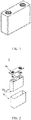
- FIG. 1 shows a secondary battery of a rectangular structure as an example.
- the outer package may include a housing 51 and a cover plate 53.
- the housing 51 may include a base plate and side plates connected to the base plate, and the base plate and the side plates enclose an accommodating cavity.
- the housing 51 has an opening communicating with the accommodating cavity, and the cover plate 53 covers the opening to close the accommodating cavity.
- a positive-electrode plate, a negative-electrode plate, and a separator may be wound or stacked to form an electrode assembly 52.
- the electrode assembly 52 is packaged in the accommodating cavity.
- the electrolyte is infiltrated into the electrode assembly 52.
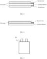
- FIG. 3 is a schematic diagram of an electrode plate with an electrode plate film layer on both surfaces of a current collector
- FIG. 4 is a schematic diagram of an electrode plate with an electrode plate film layer on only one surface of a current collector.
- the electrode assembly 52 further includes two extending tabs 521 (namely, a positive-electrode tab and a negative-electrode tab), and the two extending tabs 521 extend out from a same side of the electrode assembly.
- the positive-electrode active material is applied onto a coating zone of the positive-electrode plate, and the positive-electrode tab is formed by stacking a plurality of uncoated zones extending from the coating zone of the positive-electrode plate;
- the negative-electrode active material is applied onto a coating zone of the negative-electrode plate, and the negative-electrode tab is formed by stacking a plurality of uncoated zones extending from the coating zone of the negative-electrode plate.
- the positive-electrode/negative-electrode tab may be obtained by punching or laser die cutting.
- the two tabs may be electrically connected to corresponding electrodes (which may be disposed onto a top cover of an outer package of the battery) via respective adapting sheets, so as to lead out electric energy.
- secondary batteries may be assembled into a battery module.
- the battery module may include a plurality of secondary batteries whose quantity may be adjusted according to the use case and capacity of the battery module.
- FIG. 7 shows a battery module 4 used as an example.
- a plurality of secondary batteries 5 may be sequentially arranged in a length direction of the battery module 4.
- the secondary batteries may alternatively be arranged in any other manner.
- the plurality of secondary batteries 5 may be fastened by using fasteners.
- the battery module 4 may further include a housing with an accommodating space, and the plurality of secondary batteries 5 are accommodated in the accommodating space.
- the battery module may be further assembled into a battery pack, and a quantity of battery modules included in the battery pack may be adjusted according to the use case and capacity of the battery pack.
- FIG. 8 and FIG. 9 show a battery pack 1 as an example.
- the battery pack 1 may include a battery box and a plurality of battery modules 4 arranged in the battery box.
- the battery box includes an upper box body 2 and a lower box body 3.
- the upper box body 2 covers the lower box body 3 to form an enclosed space for accommodating the battery modules 4.
- the plurality of battery modules 4 may be arranged in the battery box in any manner.
- a second aspect of this application provides a preparation method of such secondary battery.
- the method includes the following steps: preparing an electrode plate (a positive-electrode plate and/or a negative-electrode plate) such that an electrode plate film layer has a first zone and a second zone along an extension direction of a tab, where the second zone is closer to the tab than the first zone, a thickness of the first zone is denoted as H1, a thickness of the second zone is denoted as H2, and the electrode plate satisfies 0.6 ⁇ H2/H1 ⁇ 1.
- the electrode plate film layer is obtained by using methods known to persons skilled in the art, for example, gaskets of different specifications may be used in a coating process.
- the positive-electrode plate, the separator, and the negative-electrode plate are sequentially stacked so that the separator is located between the positive-electrode plate and the negative-electrode plate to provide separation. Then, the resulting stacks are wound (or laminated) to form the electrode assembly; the electrode assembly is placed into the outer package which is filled with electrolyte after drying, followed by processes including vacuum packaging, standing, formation, and shaping, to obtain the secondary battery.
- a third aspect of this application provides an apparatus.
- the apparatus includes the secondary battery in the first aspect of this application or a secondary battery prepared by using the method according to the second aspect of this application.
- the secondary battery may be used as a power source of the apparatus or an energy storage unit of the apparatus.
- the apparatus in this application uses the secondary battery provided by this application, and therefore has at least the same advantages as the secondary battery.
- the apparatus may be, but is not limited to, a mobile device (for example, a mobile phone or a notebook computer), an electric vehicle (for example, a battery electric vehicle, a hybrid electric vehicle, a plug-in hybrid electric vehicle, an electric bicycle, an electric scooter, an electric golf vehicle, or an electric truck), an electric train, a ship, a satellite, an energy storage system, and the like.
- a mobile device for example, a mobile phone or a notebook computer
- an electric vehicle for example, a battery electric vehicle, a hybrid electric vehicle, a plug-in hybrid electric vehicle, an electric bicycle, an electric scooter, an electric golf vehicle, or an electric truck
- an electric train for example, a ship, a satellite, an energy storage system, and the like.
- a secondary battery, a battery module, or a battery pack may be selected for the apparatus according to requirements for using the apparatus.
- FIG. 10 shows an apparatus as an example.
- the apparatus is a battery electric vehicle, a hybrid electric vehicle, a plug-in hybrid electric vehicle, or the like.
- a battery pack or a battery module may be used.
- the apparatus may be a mobile phone, a tablet computer, a notebook computer, or the like.
- Such apparatus is usually required to be light and thin, and may use a secondary battery as its power source.
- a positive-electrode active material LiNi 0.8 Co 0.1 Mn 0.1 O 2 (NCM811), a conductive agent carbon black (Super P), and a binder polyvinylidene fluoride (PVDF) were uniformly mixed in a mass ratio of 96:3:1 in a proper amount of solvent N- methylpyrrolidone (NMP), to obtain a positive-electrode slurry.
- NMP N- methylpyrrolidone
- the positive-electrode slurry was applied on a positive-electrode current collector aluminum foil, followed by processes including drying, cold pressing, slitting, and cutting, to obtain a positive-electrode plate.
- Negative-electrode active material silicon monoxide and synthetic graphite were uniformly mixed at a mass ratio of 20:80, and then were uniformly mixed with a conductive agent carbon black (Super P), a binder styrene-butadiene rubber (SBR), and sodium carboxymethyl cellulose (CMC-Na) in a mass ratio of 96:1.5:1.5:1.0 in a proper amount of solvent deionized water, to obtain a negative-electrode slurry.
- the negative-electrode slurry was applied on a negative-electrode current collector copper foil, followed by processes including drying, cold pressing, slitting, and cutting, to obtain a negative-electrode plate.
- a first zone and a second zone were formed on the negative-electrode slurry during coating, where a thickness H1 of the first zone was 0.06 mm, a thickness H2 of the second zone was 0.036 mm, and a press density of a negative-electrode film layer was 1.65 g/cm 3 .
- the separator was a polyethylene (PE) film.
- Ethylene carbonate (EC) and ethyl methyl carbonate (EMC) were mixed in a mass ratio of 30:70, to obtain an organic solvent; a fully dried electrolytic salt LiPF 6 was dissolved in the above mixed solvent, with a concentration of 1.3 mol/L. Then, 6% fluoroethylene carbonate (FEC) as an additive was added into the mixed solvent, and uniformly mixed with the solvent, to obtain an electrolyte. A concentration of the electrolytic salt was calculated based on the total volume of the electrolyte, and the additive content is a weight percentage calculated based on the total weight of the electrolyte.
- FEC fluoroethylene carbonate
- the positive-electrode plate, the separator, and the negative-electrode plate were sequentially stacked, so that the separator was located between the positive-electrode plate and the negative-electrode plate to provide separation. Then, the resulting stacks were wound to form an electrode assembly.
- the electrode assembly was placed in the outer package and dried, and the prepared electrolyte was injected, followed by processes including vacuum packaging, standing, formation, and shaping, to obtain a secondary battery.
- the secondary batteries prepared in the Examples and Comparative Examples were charged to a charge cutoff voltage of 4.25 V at a constant current charge rate of 0.5C, then charged at a constant voltage until current was ⁇ 0.05C, left for 5 minutes, then discharged to a discharge cutoff voltage of 2.5 V at a constant current discharge rate of 1C, and left for 5 minutes. This was one charge and discharge cycle.
- the batteries were subjected to charge and discharge cycling until capacity of the batteries was declined to 80%. The number of cycles at that point was the cycling performance of the batteries at 25°C.
Landscapes
- Chemical & Material Sciences (AREA)
- Chemical Kinetics & Catalysis (AREA)
- Electrochemistry (AREA)
- General Chemical & Material Sciences (AREA)
- Engineering & Computer Science (AREA)
- Materials Engineering (AREA)
- Inorganic Chemistry (AREA)
- Manufacturing & Machinery (AREA)
- Battery Electrode And Active Subsutance (AREA)
- Secondary Cells (AREA)
Abstract
Description
- This application relates to a secondary battery and a preparation method thereof, and further relates to an apparatus containing such secondary battery.
- Secondary batteries have been widely used in various consumer electronic products and electric vehicles due to their prominent advantages of light weight, no pollution, and no memory effect.
- With the development of the new energy industry, people propose higher requirements for use of secondary batteries. How secondary batteries can have both high energy density and good electrochemical performance is a key challenge in the field of secondary batteries.
- In view of this, it is necessary to provide a secondary battery which delivers good performance in various aspects, so as to meet the use requirements of users.
- In view of the technical problem in the Background, this application provides a secondary battery, a preparation method thereof, and an apparatus containing such secondary battery, so that a secondary battery having high energy density also has good cycling performance.
- To achieve the above objective, a first aspect of this application provides a secondary battery. The secondary battery includes an electrode plate and a tab, and the electrode plate includes a current collector and an electrode plate film layer disposed on the current collector. The electrode plate film layer has a first zone and a second zone along an extension direction of the tab, where the second zone is closer to the tab than the first zone, a thickness of the first zone is denoted as H1, a thickness of the second zone is denoted as H2, and the secondary battery of this application satisfies 0.6 ≤ H2/H1 < 1.
- A second aspect of this application provides a preparation method of such secondary battery. The method includes the following steps: preparing an electrode plate such that the electrode plate film layer has a first zone and a second zone along an extension direction of the tab, where the second zone is closer to the tab than the first zone, a thickness of the first zone is denoted as H1, a thickness of the second zone is denoted as H2, and the electrode plate satisfies 0.6 ≤ H2/H1 < 1.
- A third aspect of this application provides an apparatus. The apparatus includes the secondary battery in the first aspect of this application or a secondary battery prepared by using the method provided in the second aspect of this application.
- Compared with the prior art, this application includes at least the following beneficial effects:
- In the secondary battery of this application, the electrode plate film layer includes the first zone and the second zone, and the first zone and the second zone satisfies a specific relationship in terms of thickness, greatly reducing the interfacial resistance and polarization of the battery. Therefore, the secondary battery of this application can have both high energy density and good cycling performance.
- To describe the technical solutions of this application more clearly, the following briefly describes the accompanying drawings used in this application. Apparently, the accompanying drawings in the following description show merely some embodiments of this application, and a person of ordinary skill in the art may still derive other drawings from these accompanying drawings without creative efforts.
-
FIG. 1 is a schematic diagram of an embodiment of a secondary battery according to this application; -
FIG. 2 is an exploded view ofFIG. 1 ; -
FIG. 3 is a schematic diagram of an embodiment of an electrode plate according to this application; -
FIG. 4 is a schematic diagram of another embodiment of an electrode plate according to this application; -
FIG. 5 is a schematic diagram of an embodiment of an electrode assembly according to this application; -
FIG. 6 is a schematic diagram of another embodiment of an electrode assembly according to this application; -
FIG. 7 is a schematic diagram of an embodiment of a battery module according to this application; -
FIG. 8 is a schematic diagram of an embodiment of a battery pack according to this application; -
FIG. 9 is an exploded view of the battery pack inFIG. 8 ; and -
FIG. 10 is a schematic diagram of an embodiment of an apparatus according to this application. - The following further describes this application with reference to embodiments. It should be understood that these specific embodiments are merely intended to illustrate this application but not to limit the scope of this application.
- For brevity, this specification specifically discloses only some numerical ranges. However, any lower limit may be combined with any upper limit to form a range not expressly recorded; any lower limit may be combined with any other lower limit to form a range not expressly recorded; and any upper limit may be combined with any other upper limit to form a range not expressly recorded. In addition, each separately disclosed point or individual value may itself be a lower limit or upper limit to be combined with any other point or individual value or combined with any other lower limit or upper limit to form a range not expressly recorded.
- In the description of this specification, it should be noted that, unless otherwise stated, "more than" and "less than" are inclusive of the present number, and "more" in "one or more" means two or more than two.
- Unless otherwise specified, terms used in this application have well-known meanings generally understood by persons skilled in the art. Unless otherwise specified, numerical values of parameters mentioned in this application may be measured by using various measurement methods commonly used in the art (for example, testing may be performed by using the methods provided in the examples of this application).
- The secondary battery of this application includes an electrode plate and a tab, and the electrode plate includes a current collector and an electrode plate film layer plate film layer disposed on the current collector. The electrode plate film layer has a first zone and a second zone along an extension direction of the tab, where the second zone is closer to the tab than the first zone, a thickness of the first zone is denoted as H1, a thickness of the second zone is denoted as H2, and the secondary battery of this application satisfies 0.6 ≤ H2/H1 < 1.
- In the secondary battery of this application, the electrode plate film layer includes different zones with a specific relationship in terms of thickness. Without wishing to be constrained by any theory, it is believed that such a structure allows a marginal space in the film layer to be reasonably designed, thereby enhancing electrolyte retention capacity of the film layer and improving infiltration of electrolyte into the film layer so as to increase the utilization efficiency of active materials and effectively improve long-term cycling performance of the battery. In addition, when thicknesses of various zones in the film layer conform to the above design, time that the electrolyte infiltrates to the inside of the film layer can be effectively shortened, so that the electrode plate is uniformly infiltrated by the electrolyte at an early stage of cycling, thereby effectively reducing resistance between the film layers, increasing the utilization efficiency of active materials, and effectively improving the overall performance of the battery.
- In the secondary battery of this application, the electrode plate may be a positive-electrode plate and/or a negative-electrode plate.
- In some preferred embodiments, the electrode plate is a negative-electrode plate.
- In the secondary battery of this application, the negative-electrode plate includes a negative-electrode current collector and a negative-electrode film layer disposed on the negative-electrode current collector, where the negative-electrode film layer includes a negative-electrode active material.
- In some preferred embodiments, the negative-electrode film layer includes a first zone and a second zone along an extension direction of the tab, where the second zone is closer to the tab than the first zone, a thickness of the first zone is denoted as H1, a thickness of the second zone is denoted as H2, and the negative-electrode film layer satisfies 0.6 ≤ H2/H1 < 1.
- In some preferred embodiments, the negative-electrode film layer satisfies 0.7 ≤ H2/H1 ≤ 0.8. When the secondary battery satisfies this range, energy density of the battery can be further improved.
- In the secondary battery of this application, if the negative-electrode film layer conforming to the above design also optionally satisfies one or more of the following parameters, performance of the battery can be further improved.
- In some preferred embodiments, the extension direction of the tab is defined as a width direction of the negative-electrode film layer, a width of the first zone is denoted as W1, a width of the second zone is denoted as W2, and the secondary battery further satisfies 0.03 ≤ W2/W1 ≤ 0.1, preferably, 0.04 ≤ W2/W1 ≤ 0.06. When the width of the first zone and that of the second zone satisfy the above condition, the infiltration performance of the electrolyte can be further improved while high energy density is ensured. This is conductive to reducing resistance between the film layers so as to improve the cycling stability of the battery.
- In some preferred embodiments, 0.04 mm ≤ H1≤ 0.15 mm, more preferably, 0.05 mm ≤ H1 ≤ 0.12 mm.
- In some preferred embodiments, 30 mm ≤ W1 ≤ 500 mm, more preferably, 60 mm≤ W1 ≤ 200 mm.
- The negative-electrode film layer satisfying the above condition can not only guarantee ease of processing of the negative-electrode plate but also ensure that the battery has enough active substances, thereby improving the energy density of the battery.
- In the secondary battery of this application, the negative-electrode current collector may be a conventional metal foil or a composite current collector (for example, a metal material may be provided on a polymer matrix to form a composite current collector). In an example, the negative-electrode current collector may be a copper foil.
- In the secondary battery of this application, the negative-electrode active material is not limited to any specific type, and any active materials that are known in the art and that can be used for negative electrodes of secondary batteries may be used, and persons skilled in the art can make selection according to actual demands.
- In an example, the negative-electrode active material may include but is not limited to one or more of synthetic graphite, natural graphite, hard carbon, soft carbon, silicon-based materials and tin-based materials. The silicon-based material may be selected from one or more of elemental silicon, silicon-oxygen compounds (such as silicon monoxide), silicon-carbon compounds, silicon-nitrogen compounds, and silicon alloys. The tin-based material may be selected from one or more of elemental tin, tin-oxygen compounds, and tin alloys. These materials are all commercially available.
- In some preferred embodiments, to further improve the energy density of the battery, the negative-electrode active material includes a silicon-based material.
- In some preferred embodiments, the silicon-based material includes a silicon-oxygen compound (for example, SiOx, 0<x<2).
- In some preferred embodiments, a mass percentage of the silicon-based material in the negative-electrode active material is ≤50%, preferably, 15%-30%. When the amount of the silicon-based material is within the given range, the battery can have both high energy density and good cycling performance.
- In some preferred embodiments, a press density PD of the negative-electrode film layer is 1.5 g/cm3 ≤ PD ≤ 1.8 g/cm3, preferably, 1.6 g/cm3 ≤ PD ≤ 1.7 g/cm3. An excessively low PD is likely to cause fall of coating from the second zone, deteriorating cycling performance of the battery. In addition, such PD also causes reduction in volumetric energy density of the battery. An excessively high PD is not conductive to de-intercalation of active ions, increasing polarization of the battery which in turn decreases capacity of the battery. In addition, such PD also greatly impacts the infiltration of electrolyte into the first zone, affecting cycling performance of the battery.
- In the secondary battery of this application, the negative-electrode film layer optionally includes a binder, a conductive agent, and other optional additives.
- In an example, the conductive agent is one or more of superconducting carbon, acetylene black, carbon black, Ketjen black, carbon dot, carbon nanotube, graphene, and carbon nanofiber.
- In an example, the binder is one or more of styrene-butadiene rubber (SBR), water-based acrylic resin (water-based acrylic resin), polyvinylidene fluoride (PVDF), polytetrafluoroethylene (PTFE), ethylene vinyl acetate (EVA), polyvinyl alcohol (PVA), and polyvinyl butyral (PVB).
- In an example, the other optional additives may be thickening and dispersing agents (such as sodium carboxymethyl cellulose CMC-Na), PTC thermistor materials, and the like.
- It can be understood that the negative-electrode current collector includes two back-to-back surfaces in a thickness direction thereof, and the negative-electrode film layer is provided on either or both of the two back-to-back surfaces of the negative-electrode current collector.
- It should be noted that the negative-electrode film layer parameters in this application all refer to parameter ranges of a film layer on one side. When the negative-electrode film layer is provided on both surfaces of the negative-electrode current collector, the parameters of the film layer on either of the two surfaces being compliant with this application are considered to fall within the protection scope of this application. In addition, thickness, width, press density, and the like of the negative-electrode film layer in this application are all parameters of a film layer cold-pressed for assembling a battery.
- In the secondary battery of this application, the positive-electrode plate includes a positive-electrode current collector and a positive-electrode film layer disposed on the positive-electrode current collector, where the positive-electrode film layer includes a positive-electrode active material.
- In some embodiments, the positive-electrode film layer includes a first zone and a second zone along an extension direction of the tab, where the second zone is closer to the tab than the first zone, a thickness of the first zone is denoted as H1, a thickness of the second zone is denoted as H2, and the positive-electrode film layer satisfies 0.6 ≤ H2/H1 < 1.
- When the positive-electrode film layer of this application conforms to the above design, for other design parameters of the first zone and second zone, reference may be made to the parameter ranges of the negative-electrode plate, without more details given herein.
- In the secondary battery of this application, the positive-electrode current collector may be a conventional metal foil or a composite current collector (a metal material may be provided on a polymer matrix to form a composite current collector). In an example, the positive-electrode current collector may be an aluminum foil.
- In the secondary battery of this application, the positive-electrode active material is not limited to any specific type, and any active materials that are known in the art and that can be used for positive electrodes of secondary batteries may be used, and persons skilled in the art can make selection according to actual demands.
- In an example, the positive-electrode active material may include but is not limited to one or more of lithium transition metal composite oxides, lithium-containing phosphates with an olivine structure, and their respective modified compounds. The lithium transition metal composite oxide may include but is not limited to one or more of lithium cobalt oxides, lithium nickel oxides, lithium manganese oxides, lithium nickel cobalt oxides, lithium manganese cobalt oxides, lithium manganese nickel oxides, lithium nickel manganese cobalt oxides, lithium nickel aluminum cobalt oxides, and modified compounds thereof. The lithium-containing phosphates with an olivine structure may include but are not limited to one or more of lithium iron phosphate, composite materials of lithium iron phosphate and carbon, lithium manganese phosphate, composite materials of lithium manganese phosphate and carbon, lithium ferric manganese phosphate, composite materials of lithium ferric manganese phosphate and carbon, and modified compounds thereof. These materials are all commercially available.
- In some preferred embodiments, to further improve the energy density of the battery, the positive-electrode active material may include one or more of lithium transition metal composite oxides shown in
formula 1 and modified compounds thereof:
LiaNibCocMdOeAf formula 1
informula 1, 0.8 ≤ a ≤ 1.2, 0.5 ≤ b < 1, 0 < c < 1, 0 < d < 1, 1 ≤ e ≤ 2, 0 ≤ f ≤ 1, M is selected from one or more of Mn, Al, Zr, Zn, Cu, Cr, Mg, Fe, V, Ti and B, and A is selected from one or more of N, F, S, and Cl. - In this application, the modified compounds of the materials may be obtained through doping modification and/or surface coating modification to the materials.
- In the secondary battery of this application, the positive-electrode film layer optionally includes a binder, a conductive agent, and other optional additives.
- In an example, the conductive agent is one or more of superconducting carbon, acetylene black, carbon black, Ketjen black, carbon dot, carbon nanotube, Super P (SP), graphene, and carbon nanofiber.
- In an example, the binder is one or more of styrene-butadiene rubber (SBR), water-based acrylic resin (water-based acrylic resin), polyvinylidene fluoride (PVDF), polytetrafluoroethylene (PTFE), ethylene vinyl acetate (EVA), polyacrylic acid (PAA), carboxymethyl cellulose (CMC), polyvinyl alcohol (PVA), and polyvinyl butyral (PVB).
- It can be understood that the positive-electrode current collector includes two back-to-back surfaces in a thickness direction thereof, and the positive-electrode film layer is provided on either or both of the two back-to-back surfaces of the positive-electrode current collector.
- It should be noted that the positive-electrode film layer parameters in this application all refer to parameter ranges of a film layer on one side. When the positive-electrode film layer is provided on both surfaces of the positive-electrode current collector, the parameters of the film layer on either of the two surfaces being compliant with this application are considered to fall within the protection scope of this application. In addition, thickness, width, and the like of the positive-electrode film layer in this application are all parameters of a film layer cold-pressed for assembling a battery.
- The secondary battery of this application further includes an electrolyte, and the electrolyte provides ion conduction between the positive-electrode plate and the negative-electrode plate. The electrolyte may include an electrolytic salt and a solvent.
- In an example, the electrolytic salt may be selected from one or more of LiPF6 (lithium hexafluorophosphate), LiBF4 (lithium tetrafluoroborate), LiClO4 (lithium perchlorate), LiAsF6 (lithium hexafluoroborate), LiFSI (lithium bis(fluorosulfonyl)bisfluorosulfonyl imide), LiTFSI (lithium bis-trifluoromethanesulfonimide), LiTFS (lithium trifluoromethanesulfonat), LiDFOB (lithium difluorooxalatoborate), LiBOB (lithium bisoxalatoborate), LiPO2F2 (lithium difluorophosphate), LiDFOP (lithium difluoro (oxalate) borate), and LiTFOP (lithium tetrafluoro oxalate phosphate).
- In an example, the solvent may be selected from one or more of ethylene carbonate (EC), propylene carbonate (PC), ethyl methyl carbonate (EMC), diethyl carbonate (DEC), dimethyl carbonate (DMC), dipropyl carbonate (DPC), methyl propyl carbonate (MPC), ethyl propyl carbonate (EPC), butylene carbonate (BC), fluoroethylene carbonate (FEC), methyl formate (MF), methyl acetate (MA), ethyl acetate (EA), propyl acetate (PA), methyl propionate (MP), ethyl propionate (EP), propyl propionate (PP), methyl butyrate (MB), ethyl butyrate (EB), 1,4-butyrolactone (GBL), tetramethylene sulfone (SF), methyl sulfonyl methane (MSM), ethyl methyl sulfone (EMS), and diethyl sulfone (ESE).
- In some preferred embodiments, the electrolyte further includes an additive. For example, the additive may include a negative-electrode film forming additive, or may include a positive-electrode film forming additive, or may include an additive capable of improving some performance of a battery, for example, an additive for improving over-charge performance of the battery, an additive for improving high-temperature performance of batteries, and an additive for improving low-temperature performance of the battery.
- The secondary battery of this application further includes a separator, and the separator is arranged between the positive-electrode plate and the negative-electrode plate to provide a separation function. This application does not impose any special limitations on the separator, and any commonly known porous separator with good chemical stability and mechanical stability may be used.
- In an example, the separator may be selected from one or more of glass fiber, non-woven fabrics, polyethylene, polypropylene, and polyvinylidene fluoride. The separator may be a single-layer thin film or a multi-layer composite thin film. When the separator is a multi-layer composite thin film, the multiple layers may be made of the same or different materials.
- All materials used in this application are commercially available.
- In this application, thickness of an electrode plate film layer has the meaning well-known in the art, and can be tested by known methods in the art. For example, the thickness may be measured by a ten-thousandths micrometer (of model Mitutoyo293-100 with 0.1µm resolution).
- In this application, width of an electrode plate film layer has the meaning well-known in the art, and can be tested by known methods in the art. For example, the width may be measured by a straight rule.
- In this application, press density of the electrode plate film layer has the meaning well-known in the art, and can be tested by known methods in the art. For example, a single-side-coated and cold-pressed electrode plate (in the case of an electrode plate having coating on both sides, a film layer on one side thereof may be wiped off firstly) is punched into a small wafer with an area of
S 1; the wafer is weighed and its weight is recorded as M1, and the thickness of the electrode plate film layer is measured by the above method and recorded as T. Then, the film layer of the weighed electrode plate is wiped off, and the negative-electrode current collector is weighed and recorded as M0. Press density PD of electrode plate film layer = (M1 - M0)/(S1 × T). - In some preferred embodiments, the secondary battery of this application is a lithium-ion secondary battery.
- In some embodiments, the above positive electrode plate, negative electrode plate, and separator may be made into an electrode assembly through winding or lamination.
- In some embodiments, the secondary battery may include an outer package. The outer package may be used for packaging the electrode assembly and the electrolyte.
- In some embodiments, the outer package of the secondary battery may be a hard shell, for example, a hard plastic shell, an aluminum shell, or a steel shell. The outer package of the secondary battery may alternatively be a soft pack, for example, a soft pouch. A material of the soft pack may be plastic, for example, one or more of polypropylene (PP), polybutylene terephthalate (PBT), polybutylene succinate (PBS), and the like.
- This application does not impose special limitations on the shape of the secondary battery, and the battery may be cylindrical, rectangular, or of any other shapes.
FIG. 1 shows a secondary battery of a rectangular structure as an example. - In some embodiments, referring to
FIG. 2 , the outer package may include ahousing 51 and acover plate 53. Thehousing 51 may include a base plate and side plates connected to the base plate, and the base plate and the side plates enclose an accommodating cavity. Thehousing 51 has an opening communicating with the accommodating cavity, and thecover plate 53 covers the opening to close the accommodating cavity. A positive-electrode plate, a negative-electrode plate, and a separator may be wound or stacked to form anelectrode assembly 52. Theelectrode assembly 52 is packaged in the accommodating cavity. The electrolyte is infiltrated into theelectrode assembly 52. There may be one ormore electrode assemblies 52 in thesecondary battery 5, and the quantity may be adjusted as required. -
FIG. 3 is a schematic diagram of an electrode plate with an electrode plate film layer on both surfaces of a current collector, andFIG. 4 is a schematic diagram of an electrode plate with an electrode plate film layer on only one surface of a current collector. - In the secondary battery of this application, referring to schematic diagrams shown in
FIG. 5 andFIG. 6 , theelectrode assembly 52 further includes two extending tabs 521 (namely, a positive-electrode tab and a negative-electrode tab), and the two extendingtabs 521 extend out from a same side of the electrode assembly. Generally, the positive-electrode active material is applied onto a coating zone of the positive-electrode plate, and the positive-electrode tab is formed by stacking a plurality of uncoated zones extending from the coating zone of the positive-electrode plate; the negative-electrode active material is applied onto a coating zone of the negative-electrode plate, and the negative-electrode tab is formed by stacking a plurality of uncoated zones extending from the coating zone of the negative-electrode plate. The positive-electrode/negative-electrode tab may be obtained by punching or laser die cutting. Furthermore, the two tabs may be electrically connected to corresponding electrodes (which may be disposed onto a top cover of an outer package of the battery) via respective adapting sheets, so as to lead out electric energy. - In some embodiments, secondary batteries may be assembled into a battery module. The battery module may include a plurality of secondary batteries whose quantity may be adjusted according to the use case and capacity of the battery module.
-
FIG. 7 shows abattery module 4 used as an example. Referring toFIG. 7 , in thebattery module 4, a plurality ofsecondary batteries 5 may be sequentially arranged in a length direction of thebattery module 4. Certainly, the secondary batteries may alternatively be arranged in any other manner. Further, the plurality ofsecondary batteries 5 may be fastened by using fasteners. - Optionally, the
battery module 4 may further include a housing with an accommodating space, and the plurality ofsecondary batteries 5 are accommodated in the accommodating space. - In some embodiments, the battery module may be further assembled into a battery pack, and a quantity of battery modules included in the battery pack may be adjusted according to the use case and capacity of the battery pack.
-
FIG. 8 andFIG. 9 show abattery pack 1 as an example. Referring toFIG. 8 andFIG. 9 , thebattery pack 1 may include a battery box and a plurality ofbattery modules 4 arranged in the battery box. The battery box includes anupper box body 2 and alower box body 3. Theupper box body 2 covers thelower box body 3 to form an enclosed space for accommodating thebattery modules 4. The plurality ofbattery modules 4 may be arranged in the battery box in any manner. - A second aspect of this application provides a preparation method of such secondary battery. The method includes the following steps: preparing an electrode plate (a positive-electrode plate and/or a negative-electrode plate) such that an electrode plate film layer has a first zone and a second zone along an extension direction of a tab, where the second zone is closer to the tab than the first zone, a thickness of the first zone is denoted as H1, a thickness of the second zone is denoted as H2, and the electrode plate satisfies 0.6 ≤ H2/H1 < 1. The electrode plate film layer is obtained by using methods known to persons skilled in the art, for example, gaskets of different specifications may be used in a coating process.
- Except for the preparation method of the electrode plate in this application, other constructing and preparation methods of the secondary battery of this application are commonly known. For example, the positive-electrode plate, the separator, and the negative-electrode plate are sequentially stacked so that the separator is located between the positive-electrode plate and the negative-electrode plate to provide separation. Then, the resulting stacks are wound (or laminated) to form the electrode assembly; the electrode assembly is placed into the outer package which is filled with electrolyte after drying, followed by processes including vacuum packaging, standing, formation, and shaping, to obtain the secondary battery.
- A third aspect of this application provides an apparatus. The apparatus includes the secondary battery in the first aspect of this application or a secondary battery prepared by using the method according to the second aspect of this application. The secondary battery may be used as a power source of the apparatus or an energy storage unit of the apparatus. The apparatus in this application uses the secondary battery provided by this application, and therefore has at least the same advantages as the secondary battery.
- The apparatus may be, but is not limited to, a mobile device (for example, a mobile phone or a notebook computer), an electric vehicle (for example, a battery electric vehicle, a hybrid electric vehicle, a plug-in hybrid electric vehicle, an electric bicycle, an electric scooter, an electric golf vehicle, or an electric truck), an electric train, a ship, a satellite, an energy storage system, and the like.
- A secondary battery, a battery module, or a battery pack may be selected for the apparatus according to requirements for using the apparatus.
-
FIG. 10 shows an apparatus as an example. The apparatus is a battery electric vehicle, a hybrid electric vehicle, a plug-in hybrid electric vehicle, or the like. To meet requirements of the apparatus for high power and high energy density of the secondary batteries, a battery pack or a battery module may be used. - In another example, the apparatus may be a mobile phone, a tablet computer, a notebook computer, or the like. Such apparatus is usually required to be light and thin, and may use a secondary battery as its power source.
- The following further describes beneficial effects of this application with reference to examples.
- To make the technical problems, technical solutions, and beneficial effects of this application clearer, the following further describes this application in detail with reference to the examples and the accompanying drawings. Apparently, the described examples are merely some but not all of the examples of this application. The following description of at least one illustrative example is merely illustrative and definitely is not construed as any limitation on this application or on use of this application. All other examples obtained by a person of ordinary skill in the art based on the examples of this application without creative efforts shall fall within the protection scope of this application.
- A positive-electrode active material LiNi0.8Co0.1Mn0.1O2 (NCM811), a conductive agent carbon black (Super P), and a binder polyvinylidene fluoride (PVDF) were uniformly mixed in a mass ratio of 96:3:1 in a proper amount of solvent N- methylpyrrolidone (NMP), to obtain a positive-electrode slurry. The positive-electrode slurry was applied on a positive-electrode current collector aluminum foil, followed by processes including drying, cold pressing, slitting, and cutting, to obtain a positive-electrode plate.
- Negative-electrode active material silicon monoxide and synthetic graphite were uniformly mixed at a mass ratio of 20:80, and then were uniformly mixed with a conductive agent carbon black (Super P), a binder styrene-butadiene rubber (SBR), and sodium carboxymethyl cellulose (CMC-Na) in a mass ratio of 96:1.5:1.5:1.0 in a proper amount of solvent deionized water, to obtain a negative-electrode slurry. The negative-electrode slurry was applied on a negative-electrode current collector copper foil, followed by processes including drying, cold pressing, slitting, and cutting, to obtain a negative-electrode plate. A first zone and a second zone were formed on the negative-electrode slurry during coating, where a thickness H1 of the first zone was 0.06 mm, a thickness H2 of the second zone was 0.036 mm, and a press density of a negative-electrode film layer was 1.65 g/cm3.
- The separator was a polyethylene (PE) film.
- Ethylene carbonate (EC) and ethyl methyl carbonate (EMC) were mixed in a mass ratio of 30:70, to obtain an organic solvent; a fully dried electrolytic salt LiPF6 was dissolved in the above mixed solvent, with a concentration of 1.3 mol/L. Then, 6% fluoroethylene carbonate (FEC) as an additive was added into the mixed solvent, and uniformly mixed with the solvent, to obtain an electrolyte. A concentration of the electrolytic salt was calculated based on the total volume of the electrolyte, and the additive content is a weight percentage calculated based on the total weight of the electrolyte.
- The positive-electrode plate, the separator, and the negative-electrode plate were sequentially stacked, so that the separator was located between the positive-electrode plate and the negative-electrode plate to provide separation. Then, the resulting stacks were wound to form an electrode assembly. The electrode assembly was placed in the outer package and dried, and the prepared electrolyte was injected, followed by processes including vacuum packaging, standing, formation, and shaping, to obtain a secondary battery.
- Secondary batteries in Examples 2 to 11 and Comparative Examples 1 to 2 were prepared in the same method as the secondary battery in Example 1 only with technical parameters for the preparation of the negative-electrode plate changed. Table 1 gives details about these different product parameters.
- At 25°C, the secondary batteries prepared in the Examples and Comparative Examples were charged to a charge cutoff voltage of 4.25 V at a constant current charge rate of 0.2C, then charged at a constant voltage until current was ≤ 0.05C, left for 5 minutes, then discharged to a discharge depth of 10% at a constant current discharge rate of 0.2C, left for 5 minutes, and finally discharged to a discharge depth of 20% at a rate of 2C (Id). Voltage after and voltage before the 2C discharge were respectively recorded as U1 and U2, and therefore discharge resistance is Rd = (U1 - U2)/Id.
- At 25°C, the secondary batteries prepared in the Examples and Comparative Examples were charged to a charge cutoff voltage of 4.25 V at a constant current charge rate of 0.5C, then charged at a constant voltage until current was ≤ 0.05C, left for 5 minutes, then discharged to a discharge cutoff voltage of 2.5 V at a constant current discharge rate of 1C, and left for 5 minutes. This was one charge and discharge cycle. The batteries were subjected to charge and discharge cycling until capacity of the batteries was declined to 80%. The number of cycles at that point was the cycling performance of the batteries at 25°C.

- According to the above comparison between the Examples 1 to 5 and the Comparative Examples 1 to 2, when the electrode plate (negative-electrode plate) of this application satisfies 0.6 ≤ H2/H1 < 1, infiltration of electrolyte into the electrode plate is effectively improved and interfacial resistance of the batteries is reduced, thereby greatly improving cycling performance of the batteries.
- According to the above Examples 3 and 6 to 11, when the electrode plate (negative-electrode plate) of this application satisfies 0.03 ≤ W2/W1 ≤ 0.1, especially when it satisfies 0.04 ≤ W2/W1 ≤ 0.06, the cycling performance of the batteries can be further improved.
- The foregoing descriptions are merely specific embodiments of this application, but are not intended to limit the protection scope of this application. Any equivalent modifications or replacements readily figured out by a person skilled in the art within the technical scope disclosed in this application shall fall within the protection scope of this application. Therefore, the scope of protection of this application shall be subject to the scope of protection of the claims.
Claims (11)
- A secondary battery, comprising an electrode plate and a tab, wherein the electrode plate comprises a current collector and an electrode plate film layer disposed on the current collector, and the electrode plate film layer has a first zone and a second zone along an extension direction of the tab, wherein the second zone is closer to the tab than the first zone, a thickness of the first zone is denoted as H1, a thickness of the second zone is denoted as H2, and the electrode plate film layer satisfies 0.6 ≤ H2/H1 < 1, preferably, 0.7 ≤ H2/H1 ≤ 0.8.
- The secondary battery according to claim 1, wherein the extension direction of the tab is defined as a width direction of the electrode plate film layer, a width of the first zone is denoted as W1, a width of the second zone is denoted as W2, and the secondary battery further satisfies 0.03 ≤ W2/W1 ≤ 0.1, preferably, 0.04 ≤ W2/W1 ≤ 0.06.
- The secondary battery according to any one of claims 1 to 2, wherein 0.04 mm ≤ H1 ≤ 0.15 mm, preferably, 0.05 mm ≤ H1 ≤ 0.12 mm.
- The secondary battery according to any one of claims 1 to 3, wherein 30 mm ≤ W1 ≤ 500 mm, preferably, 60 mm ≤ W1 ≤ 200 mm.
- The secondary battery according to any one of claims 1 to 4, wherein the electrode plate is a negative-electrode plate, and the negative-electrode plate comprises a negative-electrode current collector and a negative-electrode film layer disposed on the negative-electrode current collector.
- The secondary battery according to claim 5, wherein the negative-electrode film layer comprises a negative-electrode active material, and the negative-electrode active material comprises a silicon-based material; preferably, the silicon-based material comprises a silicon-oxygen compound.
- The secondary battery according to claim 6, wherein the mass percentage of the silicon-based material in the negative-electrode active material is ≤50%, preferably, 15%-30%.
- The secondary battery according to any one of claims 5 to 7, wherein a press density PD of the negative-electrode film layer is 1.5 g/cm3 ≤ PD ≤ 1.8 g/cm3, preferably, 1.6 g/cm3 ≤ PD ≤ 1.7 g/cm3.
- The secondary battery according to any one of claims 1 to 8, wherein the secondary battery comprises a positive-electrode plate, wherein the positive-electrode plate comprises a positive-electrode current collector and a positive-electrode film layer disposed on the positive-electrode current collector, the positive-electrode film layer comprises a positive-electrode active material, and the positive-electrode active material comprises a lithium transition metal composite oxide;preferably, the positive-electrode active material comprises one or more of lithium transition metal composite oxides shown in formula 1 and modified compounds thereof;
LiaNibCocMdOeAf formula 1
in formula 1, 0.8 ≤ a ≤ 1.2, 0.5 ≤ b < 1, 0 < c < 1, 0 < d < 1, 1 ≤ e ≤ 2, 0 ≤ f ≤ 1, M is selected from one or more of Mn, Al, Zr, Zn, Cu, Cr, Mg, Fe, V, Ti and B, and A is selected from one or more of N, F, S, and Cl. - A preparation method of secondary battery, comprising the following steps:
preparing an electrode plate such that the electrode plate film layer has a first zone and a second zone along an extension direction of a tab, wherein the second zone is closer to the tab than the first zone, a thickness of the first zone is denoted as H1, a thickness of the second zone is denoted as H2, and the electrode plate satisfies 0.6 ≤ H2/H1 < 1. - An apparatus, comprising the secondary battery according to any one of claims 1 to 9 or a secondary battery prepared by using the method according to claim 10.
Applications Claiming Priority (1)
| Application Number | Priority Date | Filing Date | Title |
|---|---|---|---|
| PCT/CN2020/091311 WO2021232288A1 (en) | 2020-05-20 | 2020-05-20 | Secondary battery and preparation method therefor, and device containing secondary battery |
Publications (2)
| Publication Number | Publication Date |
|---|---|
| EP4131554A1 true EP4131554A1 (en) | 2023-02-08 |
| EP4131554A4 EP4131554A4 (en) | 2023-11-29 |
Family
ID=78709070
Family Applications (1)
| Application Number | Title | Priority Date | Filing Date |
|---|---|---|---|
| EP20936355.5A Pending EP4131554A4 (en) | 2020-05-20 | 2020-05-20 | SECONDARY BATTERY AND PREPARATION METHOD THEREFOR, AND DEVICE COMPRISING THE SECONDARY BATTERY |
Country Status (4)
| Country | Link |
|---|---|
| US (1) | US20230080029A1 (en) |
| EP (1) | EP4131554A4 (en) |
| CN (1) | CN113966558B (en) |
| WO (1) | WO2021232288A1 (en) |
Families Citing this family (1)
| Publication number | Priority date | Publication date | Assignee | Title |
|---|---|---|---|---|
| CN119230711B (en) * | 2023-06-29 | 2025-11-18 | 宁德时代新能源科技股份有限公司 | Cathode plates, batteries and electrical equipment |
Family Cites Families (5)
| Publication number | Priority date | Publication date | Assignee | Title |
|---|---|---|---|---|
| WO2014034708A1 (en) * | 2012-08-29 | 2014-03-06 | シャープ株式会社 | Electrode plate and secondary battery |
| CN108352494B (en) * | 2015-11-06 | 2021-10-26 | 三洋电机株式会社 | Electrode plate for electricity storage device and electricity storage device |
| WO2019044526A1 (en) * | 2017-08-29 | 2019-03-07 | 株式会社村田製作所 | Battery, battery pack, electronic equipment, electric-powered vehicle, electric storage device and electric power system |
| CN109980177B (en) * | 2019-03-29 | 2021-10-22 | 东莞新能安科技有限公司 | Electrode pole piece and electrochemical device comprising the electrode pole piece |
| CN110010902A (en) * | 2019-03-29 | 2019-07-12 | 宁德新能源科技有限公司 | Electrode plates and electrochemical appliance comprising the electrode plates |
-
2020
- 2020-05-20 EP EP20936355.5A patent/EP4131554A4/en active Pending
- 2020-05-20 CN CN202080005561.4A patent/CN113966558B/en active Active
- 2020-05-20 WO PCT/CN2020/091311 patent/WO2021232288A1/en not_active Ceased
-
2022
- 2022-11-14 US US18/054,916 patent/US20230080029A1/en active Pending
Also Published As
| Publication number | Publication date |
|---|---|
| CN113966558B (en) | 2022-08-05 |
| EP4131554A4 (en) | 2023-11-29 |
| CN113966558A (en) | 2022-01-21 |
| WO2021232288A1 (en) | 2021-11-25 |
| US20230080029A1 (en) | 2023-03-16 |
Similar Documents
| Publication | Publication Date | Title |
|---|---|---|
| JP7403653B2 (en) | Secondary batteries and devices containing the secondary batteries | |
| KR102599884B1 (en) | Secondary batteries and devices containing secondary batteries | |
| KR20220036961A (en) | Secondary batteries, battery modules including secondary batteries, battery packs and devices | |
| CN117293274A (en) | Negative electrode plate, preparation method thereof, battery and power utilization device | |
| US20250149625A1 (en) | Lithium-ion battery and electric apparatus | |
| US20260031350A1 (en) | Positive electrode active material and preparation method therefor, positive electrode plate, battery, and electrical apparatus | |
| US12418047B2 (en) | Electrolyte, secondary battery, battery module, battery pack, and power consuming device | |
| US20250379220A1 (en) | Positive electrode plate and manufacturing method therefor, battery cell, battery and electrical apparatus | |
| KR20230054313A (en) | Electrode assemblies, secondary batteries, battery modules, battery packs, and devices for power consumption | |
| US20240290973A1 (en) | Electrode plate, lithium-ion battery, battery module, battery pack and electric device | |
| US20240313215A1 (en) | Positive electrode, preparation method thereof, and lithium-ion secondary battery | |
| EP4184649A1 (en) | Lithium ion battery, battery module comprising same, battery pack, and electrical apparatus | |
| US20210313585A1 (en) | Spliced lithium strip, preparation method thereof, and related negative electrode plate, battery core, lithium ion battery, battery module, battery pack and apparatus | |
| CN115956308A (en) | Lithium-ion secondary batteries, battery modules, battery packs, and power consumers | |
| JP7389245B2 (en) | A secondary battery and a device equipped with the secondary battery | |
| US20250239653A1 (en) | Electrolyte, battery, and electric apparatus | |
| US20230080029A1 (en) | Secondary battery, preparation method thereof, and apparatus containing same | |
| JP2023552027A (en) | Negative electrode plates, secondary batteries, battery modules, battery packs and power consumption devices | |
| US11996515B2 (en) | Lithium-ion secondary battery, battery module, battery pack, and power consumption apparatus | |
| US20220407117A1 (en) | Electrolyte solution, secondary battery, battery module, battery pack and device | |
| CN118315526A (en) | Positive electrode sheet and preparation method thereof, battery and electric device | |
| KR20230054311A (en) | Electrode assemblies, secondary batteries, battery modules, battery packs, and devices for power consumption | |
| CN120357010B (en) | Battery cells, battery packs and electrical devices | |
| US20240274836A1 (en) | Composite current collector, secondary battery, and electric apparatus | |
| EP4318637A1 (en) | Secondary battery and preparation method therefor, battery module, battery pack, and electric device |
Legal Events
| Date | Code | Title | Description |
|---|---|---|---|
| STAA | Information on the status of an ep patent application or granted ep patent |
Free format text: STATUS: THE INTERNATIONAL PUBLICATION HAS BEEN MADE |
|
| PUAI | Public reference made under article 153(3) epc to a published international application that has entered the european phase |
Free format text: ORIGINAL CODE: 0009012 |
|
| STAA | Information on the status of an ep patent application or granted ep patent |
Free format text: STATUS: REQUEST FOR EXAMINATION WAS MADE |
|
| 17P | Request for examination filed |
Effective date: 20221028 |
|
| AK | Designated contracting states |
Kind code of ref document: A1 Designated state(s): AL AT BE BG CH CY CZ DE DK EE ES FI FR GB GR HR HU IE IS IT LI LT LU LV MC MK MT NL NO PL PT RO RS SE SI SK SM TR |
|
| DAV | Request for validation of the european patent (deleted) | ||
| DAX | Request for extension of the european patent (deleted) | ||
| A4 | Supplementary search report drawn up and despatched |
Effective date: 20231102 |
|
| RIC1 | Information provided on ipc code assigned before grant |
Ipc: H01M 4/02 20060101ALN20231026BHEP Ipc: H01M 4/66 20060101ALI20231026BHEP Ipc: H01M 4/62 20060101ALI20231026BHEP Ipc: H01M 4/525 20100101ALI20231026BHEP Ipc: H01M 4/13 20100101ALI20231026BHEP Ipc: H01M 4/04 20060101ALI20231026BHEP Ipc: H01M 10/058 20100101AFI20231026BHEP |
|
| RAP1 | Party data changed (applicant data changed or rights of an application transferred) |
Owner name: CONTEMPORARY AMPEREX TECHNOLOGY(HONG KONG) LIMITED |
|
| STAA | Information on the status of an ep patent application or granted ep patent |
Free format text: STATUS: EXAMINATION IS IN PROGRESS |
|
| 17Q | First examination report despatched |
Effective date: 20251008 |