EP4131484A1 - Negative electrode material, negative electrode plate, electrochemical device comprising negative electrode plate and electronic device - Google Patents
Negative electrode material, negative electrode plate, electrochemical device comprising negative electrode plate and electronic device Download PDFInfo
- Publication number
- EP4131484A1 EP4131484A1 EP20926853.1A EP20926853A EP4131484A1 EP 4131484 A1 EP4131484 A1 EP 4131484A1 EP 20926853 A EP20926853 A EP 20926853A EP 4131484 A1 EP4131484 A1 EP 4131484A1
- Authority
- EP
- European Patent Office
- Prior art keywords
- particles
- negative electrode
- silicon
- electrode material
- graphite particles
- Prior art date
- Legal status (The legal status is an assumption and is not a legal conclusion. Google has not performed a legal analysis and makes no representation as to the accuracy of the status listed.)
- Pending
Links
- 239000007773 negative electrode material Substances 0.000 title claims abstract description 68
- 239000002245 particle Substances 0.000 claims abstract description 234
- OKTJSMMVPCPJKN-UHFFFAOYSA-N Carbon Chemical compound [C] OKTJSMMVPCPJKN-UHFFFAOYSA-N 0.000 claims abstract description 163
- 229910002804 graphite Inorganic materials 0.000 claims abstract description 122
- 239000010439 graphite Substances 0.000 claims abstract description 122
- 239000011856 silicon-based particle Substances 0.000 claims abstract description 91
- 238000009826 distribution Methods 0.000 claims abstract description 37
- 230000014509 gene expression Effects 0.000 claims abstract description 13
- 230000001186 cumulative effect Effects 0.000 claims abstract description 10
- 238000000576 coating method Methods 0.000 claims description 50
- 239000011248 coating agent Substances 0.000 claims description 48
- 229910052799 carbon Inorganic materials 0.000 claims description 25
- 229910052744 lithium Inorganic materials 0.000 claims description 21
- WHXSMMKQMYFTQS-UHFFFAOYSA-N Lithium Chemical compound [Li] WHXSMMKQMYFTQS-UHFFFAOYSA-N 0.000 claims description 19
- 229920002125 Sokalan® Polymers 0.000 claims description 15
- 229920000642 polymer Polymers 0.000 claims description 15
- 239000004584 polyacrylic acid Substances 0.000 claims description 14
- 239000002131 composite material Substances 0.000 claims description 11
- 238000001069 Raman spectroscopy Methods 0.000 claims description 10
- 239000011163 secondary particle Substances 0.000 claims description 10
- 239000002041 carbon nanotube Substances 0.000 claims description 9
- 229910021393 carbon nanotube Inorganic materials 0.000 claims description 9
- 239000001768 carboxy methyl cellulose Substances 0.000 claims description 9
- 229910052814 silicon oxide Inorganic materials 0.000 claims description 8
- 229910052782 aluminium Inorganic materials 0.000 claims description 7
- XAGFODPZIPBFFR-UHFFFAOYSA-N aluminium Chemical compound [Al] XAGFODPZIPBFFR-UHFFFAOYSA-N 0.000 claims description 7
- 239000002134 carbon nanofiber Substances 0.000 claims description 7
- 229910021389 graphene Inorganic materials 0.000 claims description 7
- 229920002981 polyvinylidene fluoride Polymers 0.000 claims description 7
- 229920002134 Carboxymethyl cellulose Polymers 0.000 claims description 6
- 235000010948 carboxy methyl cellulose Nutrition 0.000 claims description 6
- 239000008112 carboxymethyl-cellulose Substances 0.000 claims description 6
- 239000010936 titanium Substances 0.000 claims description 6
- RTAQQCXQSZGOHL-UHFFFAOYSA-N Titanium Chemical compound [Ti] RTAQQCXQSZGOHL-UHFFFAOYSA-N 0.000 claims description 4
- 238000002441 X-ray diffraction Methods 0.000 claims description 4
- 229910052719 titanium Inorganic materials 0.000 claims description 4
- FYYHWMGAXLPEAU-UHFFFAOYSA-N Magnesium Chemical compound [Mg] FYYHWMGAXLPEAU-UHFFFAOYSA-N 0.000 claims description 3
- 239000005062 Polybutadiene Substances 0.000 claims description 3
- 239000004793 Polystyrene Substances 0.000 claims description 3
- 229910003481 amorphous carbon Inorganic materials 0.000 claims description 3
- 239000011852 carbon nanoparticle Substances 0.000 claims description 3
- 239000011777 magnesium Substances 0.000 claims description 3
- 229910052749 magnesium Inorganic materials 0.000 claims description 3
- 229920002857 polybutadiene Polymers 0.000 claims description 3
- 229920002223 polystyrene Polymers 0.000 claims description 3
- 229920000036 polyvinylpyrrolidone Polymers 0.000 claims description 3
- 239000001267 polyvinylpyrrolidone Substances 0.000 claims description 3
- 235000013855 polyvinylpyrrolidone Nutrition 0.000 claims description 3
- HBBGRARXTFLTSG-UHFFFAOYSA-N Lithium ion Chemical compound [Li+] HBBGRARXTFLTSG-UHFFFAOYSA-N 0.000 abstract description 26
- 229910001416 lithium ion Inorganic materials 0.000 abstract description 26
- XUIMIQQOPSSXEZ-UHFFFAOYSA-N Silicon Chemical compound [Si] XUIMIQQOPSSXEZ-UHFFFAOYSA-N 0.000 description 42
- 239000010703 silicon Substances 0.000 description 42
- 229910052710 silicon Inorganic materials 0.000 description 42
- 230000000052 comparative effect Effects 0.000 description 36
- 239000008151 electrolyte solution Substances 0.000 description 21
- 239000000463 material Substances 0.000 description 19
- 238000012360 testing method Methods 0.000 description 19
- 238000011156 evaluation Methods 0.000 description 18
- 230000014759 maintenance of location Effects 0.000 description 17
- 239000000203 mixture Substances 0.000 description 17
- 239000006258 conductive agent Substances 0.000 description 16
- 239000002210 silicon-based material Substances 0.000 description 15
- 239000010410 layer Substances 0.000 description 14
- 238000000034 method Methods 0.000 description 14
- 238000002360 preparation method Methods 0.000 description 14
- 239000011230 binding agent Substances 0.000 description 12
- 238000002156 mixing Methods 0.000 description 12
- -1 polyethylene Polymers 0.000 description 12
- 238000006138 lithiation reaction Methods 0.000 description 11
- 229910052751 metal Inorganic materials 0.000 description 11
- 238000001035 drying Methods 0.000 description 10
- 229910003002 lithium salt Inorganic materials 0.000 description 10
- 159000000002 lithium salts Chemical class 0.000 description 10
- 239000002184 metal Substances 0.000 description 10
- 239000011268 mixed slurry Substances 0.000 description 10
- 239000002904 solvent Substances 0.000 description 10
- PXHVJJICTQNCMI-UHFFFAOYSA-N Nickel Chemical compound [Ni] PXHVJJICTQNCMI-UHFFFAOYSA-N 0.000 description 9
- VNWKTOKETHGBQD-UHFFFAOYSA-N methane Chemical compound C VNWKTOKETHGBQD-UHFFFAOYSA-N 0.000 description 9
- 239000000243 solution Substances 0.000 description 7
- 229920000049 Carbon (fiber) Polymers 0.000 description 6
- 238000003490 calendering Methods 0.000 description 6
- 239000004917 carbon fiber Substances 0.000 description 6
- 239000010419 fine particle Substances 0.000 description 6
- 239000007770 graphite material Substances 0.000 description 6
- 239000000843 powder Substances 0.000 description 6
- RUOJZAUFBMNUDX-UHFFFAOYSA-N propylene carbonate Chemical compound CC1COC(=O)O1 RUOJZAUFBMNUDX-UHFFFAOYSA-N 0.000 description 6
- 230000002441 reversible effect Effects 0.000 description 6
- XLYOFNOQVPJJNP-UHFFFAOYSA-N water Chemical compound O XLYOFNOQVPJJNP-UHFFFAOYSA-N 0.000 description 6
- 239000008367 deionised water Substances 0.000 description 5
- 229910021641 deionized water Inorganic materials 0.000 description 5
- 238000007599 discharging Methods 0.000 description 5
- 239000007789 gas Substances 0.000 description 5
- 239000011148 porous material Substances 0.000 description 5
- 239000007774 positive electrode material Substances 0.000 description 5
- BTBUEUYNUDRHOZ-UHFFFAOYSA-N Borate Chemical compound [O-]B([O-])[O-] BTBUEUYNUDRHOZ-UHFFFAOYSA-N 0.000 description 4
- CURLTUGMZLYLDI-UHFFFAOYSA-N Carbon dioxide Chemical compound O=C=O CURLTUGMZLYLDI-UHFFFAOYSA-N 0.000 description 4
- OIFBSDVPJOWBCH-UHFFFAOYSA-N Diethyl carbonate Chemical compound CCOC(=O)OCC OIFBSDVPJOWBCH-UHFFFAOYSA-N 0.000 description 4
- KMTRUDSVKNLOMY-UHFFFAOYSA-N Ethylene carbonate Chemical compound O=C1OCCO1 KMTRUDSVKNLOMY-UHFFFAOYSA-N 0.000 description 4
- XEEYBQQBJWHFJM-UHFFFAOYSA-N Iron Chemical compound [Fe] XEEYBQQBJWHFJM-UHFFFAOYSA-N 0.000 description 4
- 239000004698 Polyethylene Substances 0.000 description 4
- 239000004642 Polyimide Substances 0.000 description 4
- RAHZWNYVWXNFOC-UHFFFAOYSA-N Sulphur dioxide Chemical compound O=S=O RAHZWNYVWXNFOC-UHFFFAOYSA-N 0.000 description 4
- 239000011149 active material Substances 0.000 description 4
- 230000015572 biosynthetic process Effects 0.000 description 4
- 230000002950 deficient Effects 0.000 description 4
- 238000009792 diffusion process Methods 0.000 description 4
- FKRCODPIKNYEAC-UHFFFAOYSA-N ethyl propionate Chemical compound CCOC(=O)CC FKRCODPIKNYEAC-UHFFFAOYSA-N 0.000 description 4
- 238000005562 fading Methods 0.000 description 4
- 239000011888 foil Substances 0.000 description 4
- 239000003273 ketjen black Substances 0.000 description 4
- 239000003960 organic solvent Substances 0.000 description 4
- 229920000573 polyethylene Polymers 0.000 description 4
- 229920001721 polyimide Polymers 0.000 description 4
- 239000011164 primary particle Substances 0.000 description 4
- 238000012545 processing Methods 0.000 description 4
- 239000002002 slurry Substances 0.000 description 4
- 238000003756 stirring Methods 0.000 description 4
- 239000000126 substance Substances 0.000 description 4
- 229910052723 transition metal Inorganic materials 0.000 description 4
- 150000003624 transition metals Chemical class 0.000 description 4
- 238000004804 winding Methods 0.000 description 4
- DGAQECJNVWCQMB-PUAWFVPOSA-M Ilexoside XXIX Chemical compound C[C@@H]1CC[C@@]2(CC[C@@]3(C(=CC[C@H]4[C@]3(CC[C@@H]5[C@@]4(CC[C@@H](C5(C)C)OS(=O)(=O)[O-])C)C)[C@@H]2[C@]1(C)O)C)C(=O)O[C@H]6[C@@H]([C@H]([C@@H]([C@H](O6)CO)O)O)O.[Na+] DGAQECJNVWCQMB-PUAWFVPOSA-M 0.000 description 3
- SECXISVLQFMRJM-UHFFFAOYSA-N N-Methylpyrrolidone Chemical compound CN1CCCC1=O SECXISVLQFMRJM-UHFFFAOYSA-N 0.000 description 3
- VYPSYNLAJGMNEJ-UHFFFAOYSA-N Silicium dioxide Chemical compound O=[Si]=O VYPSYNLAJGMNEJ-UHFFFAOYSA-N 0.000 description 3
- OBNDGIHQAIXEAO-UHFFFAOYSA-N [O].[Si] Chemical compound [O].[Si] OBNDGIHQAIXEAO-UHFFFAOYSA-N 0.000 description 3
- DPXJVFZANSGRMM-UHFFFAOYSA-N acetic acid;2,3,4,5,6-pentahydroxyhexanal;sodium Chemical compound [Na].CC(O)=O.OCC(O)C(O)C(O)C(O)C=O DPXJVFZANSGRMM-UHFFFAOYSA-N 0.000 description 3
- 230000002411 adverse Effects 0.000 description 3
- 230000005540 biological transmission Effects 0.000 description 3
- 238000004806 packaging method and process Methods 0.000 description 3
- 238000012856 packing Methods 0.000 description 3
- 230000010287 polarization Effects 0.000 description 3
- 229920006254 polymer film Polymers 0.000 description 3
- 230000008569 process Effects 0.000 description 3
- 238000007789 sealing Methods 0.000 description 3
- 229910052708 sodium Inorganic materials 0.000 description 3
- 239000011734 sodium Substances 0.000 description 3
- 235000019812 sodium carboxymethyl cellulose Nutrition 0.000 description 3
- 229920001027 sodium carboxymethylcellulose Polymers 0.000 description 3
- 238000005303 weighing Methods 0.000 description 3
- SBLRHMKNNHXPHG-UHFFFAOYSA-N 4-fluoro-1,3-dioxolan-2-one Chemical compound FC1COC(=O)O1 SBLRHMKNNHXPHG-UHFFFAOYSA-N 0.000 description 2
- RYGMFSIKBFXOCR-UHFFFAOYSA-N Copper Chemical compound [Cu] RYGMFSIKBFXOCR-UHFFFAOYSA-N 0.000 description 2
- 229910000881 Cu alloy Inorganic materials 0.000 description 2
- 229910000570 Cupronickel Inorganic materials 0.000 description 2
- 229910001290 LiPF6 Inorganic materials 0.000 description 2
- 229910000990 Ni alloy Inorganic materials 0.000 description 2
- 239000002033 PVDF binder Substances 0.000 description 2
- 239000004962 Polyamide-imide Substances 0.000 description 2
- 239000004743 Polypropylene Substances 0.000 description 2
- 239000004372 Polyvinyl alcohol Substances 0.000 description 2
- ZLMJMSJWJFRBEC-UHFFFAOYSA-N Potassium Chemical compound [K] ZLMJMSJWJFRBEC-UHFFFAOYSA-N 0.000 description 2
- NINIDFKCEFEMDL-UHFFFAOYSA-N Sulfur Chemical compound [S] NINIDFKCEFEMDL-UHFFFAOYSA-N 0.000 description 2
- 230000001133 acceleration Effects 0.000 description 2
- 239000000654 additive Substances 0.000 description 2
- 230000000996 additive effect Effects 0.000 description 2
- 238000004458 analytical method Methods 0.000 description 2
- 125000004429 atom Chemical group 0.000 description 2
- 229910002092 carbon dioxide Inorganic materials 0.000 description 2
- 239000001569 carbon dioxide Substances 0.000 description 2
- 229910017052 cobalt Inorganic materials 0.000 description 2
- 239000010941 cobalt Substances 0.000 description 2
- GUTLYIVDDKVIGB-UHFFFAOYSA-N cobalt atom Chemical compound [Co] GUTLYIVDDKVIGB-UHFFFAOYSA-N 0.000 description 2
- 150000001875 compounds Chemical class 0.000 description 2
- 229910052802 copper Inorganic materials 0.000 description 2
- 239000010949 copper Substances 0.000 description 2
- 238000005260 corrosion Methods 0.000 description 2
- 230000007797 corrosion Effects 0.000 description 2
- 230000007423 decrease Effects 0.000 description 2
- 230000002542 deteriorative effect Effects 0.000 description 2
- IEJIGPNLZYLLBP-UHFFFAOYSA-N dimethyl carbonate Chemical compound COC(=O)OC IEJIGPNLZYLLBP-UHFFFAOYSA-N 0.000 description 2
- 238000007323 disproportionation reaction Methods 0.000 description 2
- 230000000694 effects Effects 0.000 description 2
- JBTWLSYIZRCDFO-UHFFFAOYSA-N ethyl methyl carbonate Chemical compound CCOC(=O)OC JBTWLSYIZRCDFO-UHFFFAOYSA-N 0.000 description 2
- 239000000706 filtrate Substances 0.000 description 2
- 239000011521 glass Substances 0.000 description 2
- 239000003365 glass fiber Substances 0.000 description 2
- 125000004435 hydrogen atom Chemical group [H]* 0.000 description 2
- 238000002354 inductively-coupled plasma atomic emission spectroscopy Methods 0.000 description 2
- 238000009830 intercalation Methods 0.000 description 2
- 230000002687 intercalation Effects 0.000 description 2
- 230000016507 interphase Effects 0.000 description 2
- 229910052742 iron Inorganic materials 0.000 description 2
- 229910003473 lithium bis(trifluoromethanesulfonyl)imide Inorganic materials 0.000 description 2
- 229910001496 lithium tetrafluoroborate Inorganic materials 0.000 description 2
- VDVLPSWVDYJFRW-UHFFFAOYSA-N lithium;bis(fluorosulfonyl)azanide Chemical compound [Li+].FS(=O)(=O)[N-]S(F)(=O)=O VDVLPSWVDYJFRW-UHFFFAOYSA-N 0.000 description 2
- QSZMZKBZAYQGRS-UHFFFAOYSA-N lithium;bis(trifluoromethylsulfonyl)azanide Chemical compound [Li+].FC(F)(F)S(=O)(=O)[N-]S(=O)(=O)C(F)(F)F QSZMZKBZAYQGRS-UHFFFAOYSA-N 0.000 description 2
- IGILRSKEFZLPKG-UHFFFAOYSA-M lithium;difluorophosphinate Chemical compound [Li+].[O-]P(F)(F)=O IGILRSKEFZLPKG-UHFFFAOYSA-M 0.000 description 2
- WPBNNNQJVZRUHP-UHFFFAOYSA-L manganese(2+);methyl n-[[2-(methoxycarbonylcarbamothioylamino)phenyl]carbamothioyl]carbamate;n-[2-(sulfidocarbothioylamino)ethyl]carbamodithioate Chemical compound [Mn+2].[S-]C(=S)NCCNC([S-])=S.COC(=O)NC(=S)NC1=CC=CC=C1NC(=S)NC(=O)OC WPBNNNQJVZRUHP-UHFFFAOYSA-L 0.000 description 2
- 238000004519 manufacturing process Methods 0.000 description 2
- 239000002048 multi walled nanotube Substances 0.000 description 2
- 229910052759 nickel Inorganic materials 0.000 description 2
- 238000011056 performance test Methods 0.000 description 2
- 229920002312 polyamide-imide Polymers 0.000 description 2
- 229920000728 polyester Polymers 0.000 description 2
- 229920001155 polypropylene Polymers 0.000 description 2
- 229920001343 polytetrafluoroethylene Polymers 0.000 description 2
- 239000004810 polytetrafluoroethylene Substances 0.000 description 2
- 229920002451 polyvinyl alcohol Polymers 0.000 description 2
- 235000019422 polyvinyl alcohol Nutrition 0.000 description 2
- 229910052700 potassium Inorganic materials 0.000 description 2
- 239000011591 potassium Substances 0.000 description 2
- 239000000047 product Substances 0.000 description 2
- 239000002109 single walled nanotube Substances 0.000 description 2
- 239000007787 solid Substances 0.000 description 2
- 239000007784 solid electrolyte Substances 0.000 description 2
- 229920003048 styrene butadiene rubber Polymers 0.000 description 2
- 229910052717 sulfur Inorganic materials 0.000 description 2
- 239000011593 sulfur Substances 0.000 description 2
- QGZKDVFQNNGYKY-UHFFFAOYSA-O Ammonium Chemical compound [NH4+] QGZKDVFQNNGYKY-UHFFFAOYSA-O 0.000 description 1
- 229910032387 LiCoO2 Inorganic materials 0.000 description 1
- GRYLNZFGIOXLOG-UHFFFAOYSA-N Nitric acid Chemical compound O[N+]([O-])=O GRYLNZFGIOXLOG-UHFFFAOYSA-N 0.000 description 1
- 238000010521 absorption reaction Methods 0.000 description 1
- 238000005054 agglomeration Methods 0.000 description 1
- 230000002776 aggregation Effects 0.000 description 1
- 239000012300 argon atmosphere Substances 0.000 description 1
- QVGXLLKOCUKJST-UHFFFAOYSA-N atomic oxygen Chemical compound [O] QVGXLLKOCUKJST-UHFFFAOYSA-N 0.000 description 1
- 230000009286 beneficial effect Effects 0.000 description 1
- 238000004140 cleaning Methods 0.000 description 1
- 238000012937 correction Methods 0.000 description 1
- 239000013078 crystal Substances 0.000 description 1
- 238000005520 cutting process Methods 0.000 description 1
- 230000003247 decreasing effect Effects 0.000 description 1
- 238000007872 degassing Methods 0.000 description 1
- 238000009831 deintercalation Methods 0.000 description 1
- 239000007772 electrode material Substances 0.000 description 1
- 238000005516 engineering process Methods 0.000 description 1
- 230000007613 environmental effect Effects 0.000 description 1
- 238000002474 experimental method Methods 0.000 description 1
- 238000001914 filtration Methods 0.000 description 1
- 238000005324 grain boundary diffusion Methods 0.000 description 1
- 238000010438 heat treatment Methods 0.000 description 1
- 230000006872 improvement Effects 0.000 description 1
- 150000002500 ions Chemical class 0.000 description 1
- 238000011068 loading method Methods 0.000 description 1
- YQCIWBXEVYWRCW-UHFFFAOYSA-N methane;sulfane Chemical compound C.S YQCIWBXEVYWRCW-UHFFFAOYSA-N 0.000 description 1
- 238000012986 modification Methods 0.000 description 1
- 230000004048 modification Effects 0.000 description 1
- 239000005543 nano-size silicon particle Substances 0.000 description 1
- 229910017604 nitric acid Inorganic materials 0.000 description 1
- 239000001301 oxygen Substances 0.000 description 1
- 229910052760 oxygen Inorganic materials 0.000 description 1
- 239000002985 plastic film Substances 0.000 description 1
- 229920006255 plastic film Polymers 0.000 description 1
- 230000005855 radiation Effects 0.000 description 1
- 239000002994 raw material Substances 0.000 description 1
- 238000009877 rendering Methods 0.000 description 1
- 238000011160 research Methods 0.000 description 1
- 239000002356 single layer Substances 0.000 description 1
- 238000001179 sorption measurement Methods 0.000 description 1
- 239000004094 surface-active agent Substances 0.000 description 1
- ZSDSQXJSNMTJDA-UHFFFAOYSA-N trifluralin Chemical compound CCCN(CCC)C1=C([N+]([O-])=O)C=C(C(F)(F)F)C=C1[N+]([O-])=O ZSDSQXJSNMTJDA-UHFFFAOYSA-N 0.000 description 1
- 238000004506 ultrasonic cleaning Methods 0.000 description 1
- 238000005406 washing Methods 0.000 description 1
Images

Classifications
-
- H—ELECTRICITY
- H01—ELECTRIC ELEMENTS
- H01M—PROCESSES OR MEANS, e.g. BATTERIES, FOR THE DIRECT CONVERSION OF CHEMICAL ENERGY INTO ELECTRICAL ENERGY
- H01M4/00—Electrodes
- H01M4/02—Electrodes composed of, or comprising, active material
- H01M4/13—Electrodes for accumulators with non-aqueous electrolyte, e.g. for lithium-accumulators; Processes of manufacture thereof
- H01M4/131—Electrodes based on mixed oxides or hydroxides, or on mixtures of oxides or hydroxides, e.g. LiCoOx
-
- H—ELECTRICITY
- H01—ELECTRIC ELEMENTS
- H01M—PROCESSES OR MEANS, e.g. BATTERIES, FOR THE DIRECT CONVERSION OF CHEMICAL ENERGY INTO ELECTRICAL ENERGY
- H01M4/00—Electrodes
- H01M4/02—Electrodes composed of, or comprising, active material
- H01M4/13—Electrodes for accumulators with non-aqueous electrolyte, e.g. for lithium-accumulators; Processes of manufacture thereof
- H01M4/133—Electrodes based on carbonaceous material, e.g. graphite-intercalation compounds or CFx
-
- C—CHEMISTRY; METALLURGY
- C01—INORGANIC CHEMISTRY
- C01B—NON-METALLIC ELEMENTS; COMPOUNDS THEREOF; METALLOIDS OR COMPOUNDS THEREOF NOT COVERED BY SUBCLASS C01C
- C01B32/00—Carbon; Compounds thereof
- C01B32/20—Graphite
-
- C—CHEMISTRY; METALLURGY
- C01—INORGANIC CHEMISTRY
- C01B—NON-METALLIC ELEMENTS; COMPOUNDS THEREOF; METALLOIDS OR COMPOUNDS THEREOF NOT COVERED BY SUBCLASS C01C
- C01B33/00—Silicon; Compounds thereof
- C01B33/113—Silicon oxides; Hydrates thereof
-
- H—ELECTRICITY
- H01—ELECTRIC ELEMENTS
- H01M—PROCESSES OR MEANS, e.g. BATTERIES, FOR THE DIRECT CONVERSION OF CHEMICAL ENERGY INTO ELECTRICAL ENERGY
- H01M10/00—Secondary cells; Manufacture thereof
- H01M10/05—Accumulators with non-aqueous electrolyte
- H01M10/052—Li-accumulators
-
- H—ELECTRICITY
- H01—ELECTRIC ELEMENTS
- H01M—PROCESSES OR MEANS, e.g. BATTERIES, FOR THE DIRECT CONVERSION OF CHEMICAL ENERGY INTO ELECTRICAL ENERGY
- H01M10/00—Secondary cells; Manufacture thereof
- H01M10/05—Accumulators with non-aqueous electrolyte
- H01M10/052—Li-accumulators
- H01M10/0525—Rocking-chair batteries, i.e. batteries with lithium insertion or intercalation in both electrodes; Lithium-ion batteries
-
- H—ELECTRICITY
- H01—ELECTRIC ELEMENTS
- H01M—PROCESSES OR MEANS, e.g. BATTERIES, FOR THE DIRECT CONVERSION OF CHEMICAL ENERGY INTO ELECTRICAL ENERGY
- H01M4/00—Electrodes
- H01M4/02—Electrodes composed of, or comprising, active material
- H01M4/04—Processes of manufacture in general
- H01M4/0471—Processes of manufacture in general involving thermal treatment, e.g. firing, sintering, backing particulate active material, thermal decomposition, pyrolysis
-
- H—ELECTRICITY
- H01—ELECTRIC ELEMENTS
- H01M—PROCESSES OR MEANS, e.g. BATTERIES, FOR THE DIRECT CONVERSION OF CHEMICAL ENERGY INTO ELECTRICAL ENERGY
- H01M4/00—Electrodes
- H01M4/02—Electrodes composed of, or comprising, active material
- H01M4/13—Electrodes for accumulators with non-aqueous electrolyte, e.g. for lithium-accumulators; Processes of manufacture thereof
- H01M4/134—Electrodes based on metals, Si or alloys
-
- H—ELECTRICITY
- H01—ELECTRIC ELEMENTS
- H01M—PROCESSES OR MEANS, e.g. BATTERIES, FOR THE DIRECT CONVERSION OF CHEMICAL ENERGY INTO ELECTRICAL ENERGY
- H01M4/00—Electrodes
- H01M4/02—Electrodes composed of, or comprising, active material
- H01M4/13—Electrodes for accumulators with non-aqueous electrolyte, e.g. for lithium-accumulators; Processes of manufacture thereof
- H01M4/139—Processes of manufacture
- H01M4/1395—Processes of manufacture of electrodes based on metals, Si or alloys
-
- H—ELECTRICITY
- H01—ELECTRIC ELEMENTS
- H01M—PROCESSES OR MEANS, e.g. BATTERIES, FOR THE DIRECT CONVERSION OF CHEMICAL ENERGY INTO ELECTRICAL ENERGY
- H01M4/00—Electrodes
- H01M4/02—Electrodes composed of, or comprising, active material
- H01M4/36—Selection of substances as active materials, active masses, active liquids
-
- H—ELECTRICITY
- H01—ELECTRIC ELEMENTS
- H01M—PROCESSES OR MEANS, e.g. BATTERIES, FOR THE DIRECT CONVERSION OF CHEMICAL ENERGY INTO ELECTRICAL ENERGY
- H01M4/00—Electrodes
- H01M4/02—Electrodes composed of, or comprising, active material
- H01M4/36—Selection of substances as active materials, active masses, active liquids
- H01M4/362—Composites
- H01M4/364—Composites as mixtures
-
- H—ELECTRICITY
- H01—ELECTRIC ELEMENTS
- H01M—PROCESSES OR MEANS, e.g. BATTERIES, FOR THE DIRECT CONVERSION OF CHEMICAL ENERGY INTO ELECTRICAL ENERGY
- H01M4/00—Electrodes
- H01M4/02—Electrodes composed of, or comprising, active material
- H01M4/36—Selection of substances as active materials, active masses, active liquids
- H01M4/362—Composites
- H01M4/366—Composites as layered products
-
- H—ELECTRICITY
- H01—ELECTRIC ELEMENTS
- H01M—PROCESSES OR MEANS, e.g. BATTERIES, FOR THE DIRECT CONVERSION OF CHEMICAL ENERGY INTO ELECTRICAL ENERGY
- H01M4/00—Electrodes
- H01M4/02—Electrodes composed of, or comprising, active material
- H01M4/36—Selection of substances as active materials, active masses, active liquids
- H01M4/38—Selection of substances as active materials, active masses, active liquids of elements or alloys
-
- H—ELECTRICITY
- H01—ELECTRIC ELEMENTS
- H01M—PROCESSES OR MEANS, e.g. BATTERIES, FOR THE DIRECT CONVERSION OF CHEMICAL ENERGY INTO ELECTRICAL ENERGY
- H01M4/00—Electrodes
- H01M4/02—Electrodes composed of, or comprising, active material
- H01M4/36—Selection of substances as active materials, active masses, active liquids
- H01M4/38—Selection of substances as active materials, active masses, active liquids of elements or alloys
- H01M4/386—Silicon or alloys based on silicon
-
- H—ELECTRICITY
- H01—ELECTRIC ELEMENTS
- H01M—PROCESSES OR MEANS, e.g. BATTERIES, FOR THE DIRECT CONVERSION OF CHEMICAL ENERGY INTO ELECTRICAL ENERGY
- H01M4/00—Electrodes
- H01M4/02—Electrodes composed of, or comprising, active material
- H01M4/36—Selection of substances as active materials, active masses, active liquids
- H01M4/48—Selection of substances as active materials, active masses, active liquids of inorganic oxides or hydroxides
- H01M4/483—Selection of substances as active materials, active masses, active liquids of inorganic oxides or hydroxides for non-aqueous cells
-
- H—ELECTRICITY
- H01—ELECTRIC ELEMENTS
- H01M—PROCESSES OR MEANS, e.g. BATTERIES, FOR THE DIRECT CONVERSION OF CHEMICAL ENERGY INTO ELECTRICAL ENERGY
- H01M4/00—Electrodes
- H01M4/02—Electrodes composed of, or comprising, active material
- H01M4/36—Selection of substances as active materials, active masses, active liquids
- H01M4/48—Selection of substances as active materials, active masses, active liquids of inorganic oxides or hydroxides
- H01M4/485—Selection of substances as active materials, active masses, active liquids of inorganic oxides or hydroxides of mixed oxides or hydroxides for inserting or intercalating light metals, e.g. LiTi2O4 or LiTi2OxFy
-
- H—ELECTRICITY
- H01—ELECTRIC ELEMENTS
- H01M—PROCESSES OR MEANS, e.g. BATTERIES, FOR THE DIRECT CONVERSION OF CHEMICAL ENERGY INTO ELECTRICAL ENERGY
- H01M4/00—Electrodes
- H01M4/02—Electrodes composed of, or comprising, active material
- H01M4/36—Selection of substances as active materials, active masses, active liquids
- H01M4/58—Selection of substances as active materials, active masses, active liquids of inorganic compounds other than oxides or hydroxides, e.g. sulfides, selenides, tellurides, halogenides or LiCoFy; of polyanionic structures, e.g. phosphates, silicates or borates
- H01M4/583—Carbonaceous material, e.g. graphite-intercalation compounds or CFx
- H01M4/587—Carbonaceous material, e.g. graphite-intercalation compounds or CFx for inserting or intercalating light metals
-
- H—ELECTRICITY
- H01—ELECTRIC ELEMENTS
- H01M—PROCESSES OR MEANS, e.g. BATTERIES, FOR THE DIRECT CONVERSION OF CHEMICAL ENERGY INTO ELECTRICAL ENERGY
- H01M4/00—Electrodes
- H01M4/02—Electrodes composed of, or comprising, active material
- H01M4/62—Selection of inactive substances as ingredients for active masses, e.g. binders, fillers
-
- H—ELECTRICITY
- H01—ELECTRIC ELEMENTS
- H01M—PROCESSES OR MEANS, e.g. BATTERIES, FOR THE DIRECT CONVERSION OF CHEMICAL ENERGY INTO ELECTRICAL ENERGY
- H01M4/00—Electrodes
- H01M4/02—Electrodes composed of, or comprising, active material
- H01M4/62—Selection of inactive substances as ingredients for active masses, e.g. binders, fillers
- H01M4/621—Binders
- H01M4/622—Binders being polymers
-
- H—ELECTRICITY
- H01—ELECTRIC ELEMENTS
- H01M—PROCESSES OR MEANS, e.g. BATTERIES, FOR THE DIRECT CONVERSION OF CHEMICAL ENERGY INTO ELECTRICAL ENERGY
- H01M4/00—Electrodes
- H01M4/02—Electrodes composed of, or comprising, active material
- H01M4/62—Selection of inactive substances as ingredients for active masses, e.g. binders, fillers
- H01M4/624—Electric conductive fillers
- H01M4/625—Carbon or graphite
-
- H—ELECTRICITY
- H01—ELECTRIC ELEMENTS
- H01M—PROCESSES OR MEANS, e.g. BATTERIES, FOR THE DIRECT CONVERSION OF CHEMICAL ENERGY INTO ELECTRICAL ENERGY
- H01M4/00—Electrodes
- H01M4/02—Electrodes composed of, or comprising, active material
- H01M4/64—Carriers or collectors
- H01M4/66—Selection of materials
- H01M4/661—Metal or alloys, e.g. alloy coatings
-
- C—CHEMISTRY; METALLURGY
- C01—INORGANIC CHEMISTRY
- C01P—INDEXING SCHEME RELATING TO STRUCTURAL AND PHYSICAL ASPECTS OF SOLID INORGANIC COMPOUNDS
- C01P2002/00—Crystal-structural characteristics
- C01P2002/70—Crystal-structural characteristics defined by measured X-ray, neutron or electron diffraction data
- C01P2002/74—Crystal-structural characteristics defined by measured X-ray, neutron or electron diffraction data by peak-intensities or a ratio thereof only
-
- C—CHEMISTRY; METALLURGY
- C01—INORGANIC CHEMISTRY
- C01P—INDEXING SCHEME RELATING TO STRUCTURAL AND PHYSICAL ASPECTS OF SOLID INORGANIC COMPOUNDS
- C01P2002/00—Crystal-structural characteristics
- C01P2002/80—Crystal-structural characteristics defined by measured data other than those specified in group C01P2002/70
- C01P2002/82—Crystal-structural characteristics defined by measured data other than those specified in group C01P2002/70 by IR- or Raman-data
-
- C—CHEMISTRY; METALLURGY
- C01—INORGANIC CHEMISTRY
- C01P—INDEXING SCHEME RELATING TO STRUCTURAL AND PHYSICAL ASPECTS OF SOLID INORGANIC COMPOUNDS
- C01P2004/00—Particle morphology
- C01P2004/51—Particles with a specific particle size distribution
-
- C—CHEMISTRY; METALLURGY
- C01—INORGANIC CHEMISTRY
- C01P—INDEXING SCHEME RELATING TO STRUCTURAL AND PHYSICAL ASPECTS OF SOLID INORGANIC COMPOUNDS
- C01P2004/00—Particle morphology
- C01P2004/60—Particles characterised by their size
-
- C—CHEMISTRY; METALLURGY
- C01—INORGANIC CHEMISTRY
- C01P—INDEXING SCHEME RELATING TO STRUCTURAL AND PHYSICAL ASPECTS OF SOLID INORGANIC COMPOUNDS
- C01P2004/00—Particle morphology
- C01P2004/90—Other morphology not specified above
-
- C—CHEMISTRY; METALLURGY
- C01—INORGANIC CHEMISTRY
- C01P—INDEXING SCHEME RELATING TO STRUCTURAL AND PHYSICAL ASPECTS OF SOLID INORGANIC COMPOUNDS
- C01P2006/00—Physical properties of inorganic compounds
- C01P2006/12—Surface area
-
- H—ELECTRICITY
- H01—ELECTRIC ELEMENTS
- H01M—PROCESSES OR MEANS, e.g. BATTERIES, FOR THE DIRECT CONVERSION OF CHEMICAL ENERGY INTO ELECTRICAL ENERGY
- H01M4/00—Electrodes
- H01M4/02—Electrodes composed of, or comprising, active material
- H01M2004/021—Physical characteristics, e.g. porosity, surface area
-
- H—ELECTRICITY
- H01—ELECTRIC ELEMENTS
- H01M—PROCESSES OR MEANS, e.g. BATTERIES, FOR THE DIRECT CONVERSION OF CHEMICAL ENERGY INTO ELECTRICAL ENERGY
- H01M4/00—Electrodes
- H01M4/02—Electrodes composed of, or comprising, active material
- H01M2004/026—Electrodes composed of, or comprising, active material characterised by the polarity
- H01M2004/027—Negative electrodes
-
- Y—GENERAL TAGGING OF NEW TECHNOLOGICAL DEVELOPMENTS; GENERAL TAGGING OF CROSS-SECTIONAL TECHNOLOGIES SPANNING OVER SEVERAL SECTIONS OF THE IPC; TECHNICAL SUBJECTS COVERED BY FORMER USPC CROSS-REFERENCE ART COLLECTIONS [XRACs] AND DIGESTS
- Y02—TECHNOLOGIES OR APPLICATIONS FOR MITIGATION OR ADAPTATION AGAINST CLIMATE CHANGE
- Y02E—REDUCTION OF GREENHOUSE GAS [GHG] EMISSIONS, RELATED TO ENERGY GENERATION, TRANSMISSION OR DISTRIBUTION
- Y02E60/00—Enabling technologies; Technologies with a potential or indirect contribution to GHG emissions mitigation
- Y02E60/10—Energy storage using batteries
Definitions
- the present invention relates to the technical field of batteries, in particular, to the technical field of lithium-ion batteries, and specifically, to a negative electrode material, a negative electrode plate coated with the negative electrode material, an electrochemical device containing the negative electrode plate, and an electronic device.
- a silicon-based material can significantly increase an energy density of a battery.
- a silicon-oxygen material in the silicon-based materials possesses the advantages such as a high specific capacity (2400 mAh/g), abundant raw material sources, and environmental friendliness.
- a hybrid negative electrode made of the silicon-oxygen material incurs a relatively high degree of volume expansion and shrinkage during deintercalation and intercalation. This makes the silicon-oxygen material particles keep migrating, increases a porosity of the negative electrode plate, leads to failure of connection between active materials in the electrode plate, increases a capacity fading speed and a deformation rate of the battery, and severely impairs the effect of the material in practical applications.
- one of objectives of the present invention is to provide a negative electrode material to improve cycle performance and a deformation rate of a battery by means of reasonable matching of morphology and particle size between a silicon-based material and a graphite material.
- characteristics such as particle size distribution, sphericity, and XRD features of the silicon-based particles and graphite particles are further defined to obtain a negative electrode material of higher performance.
- Another objective of the present invention is to provide a negative electrode plate containing the foregoing negative electrode material, a method for preparing the negative electrode plate, a lithium-ion secondary battery, a method for preparing the lithium-ion secondary battery, an electrochemical device, and an electronic device.
- the present invention provides a negative electrode material.
- the negative electrode material contains silicon-based particles and graphite particles.
- a D n50 /D v50 ratio of the graphite particles is A
- a D n50 /D v50 ratio of the silicon-based particles is B
- the following conditional expressions (1) to (3) are satisfied: 0.1 ⁇ A ⁇ 0.65 0.3 ⁇ B ⁇ 0.85 and B > A
- D v50 is a particle diameter of particles measured when a cumulative volume fraction in a volume-based distribution reaches 50%; and D n50 is a particle diameter of particles measured when a cumulative number fraction in a number-based distribution reaches 50%.
- D n50 /D v50 is a ratio of D n50 to D v50 measured by a laser scattering particle size analyzer. The closer the value is to 1, the more concentrated the particle size distribution.
- the concentration degree of the graphite particles is lower than the concentration degree of the silicon-based particles, the battery exhibits higher cycle performance and a lower deformation rate. That is because lithiation-induced expansion of the silicon-based material is much larger than that of the graphite material.
- an average particle diameter of the silicon-based particles is set to be smaller than an average particle diameter of the graphite particles.
- the distribution of the silicon-based particles is more concentrated than the distribution of the graphite particles. This helps to disperse the silicon-based particles into voids between the packed graphite particles, and minimizes the impact caused by the expansion of the silicon-based material onto the overall expansion of the electrode plate, thereby improving the cycle performance and deformation rate of the battery.
- the D n50 /D v50 ratio of the graphite particles falls within the range of 0.1 to 0.65, electrical performance of the battery is relatively high.
- the D n50 /D v50 ratio of the graphite particles is less than 0.1, there are excessive fine particles and large particles in the graphite particles.
- the excessive fine particles lead to an excessive specific surface area of the material, and reduce the first-cycle Coulombic efficiency.
- the excessive large particles increase a transmission distance of lithium ions, aggravate the deformation of the battery, and deteriorate rate performance of the battery.
- the electrical performance of the battery is relatively high.
- the D n50 /D v50 ratio of the silicon-based particles is less than 0.3, the distribution of the silicon-based particles is lowly concentrated, and numerous oversized or undersized silicon-based particles exist. The excessive number of the undersized silicon-based particles increases the area of contacting the electrolytic solution, generates a larger amount of solid electrolyte interphase film (SEI film), and consumes the limited reversible lithium in the battery.
- SEI film solid electrolyte interphase film
- the oversized silicon-based particles increase the stress generated during the lithiation-induced expansion, cause the silicon-based particles to rupture, make a fresh interface exposed to react with the electrolytic solution, consume reversible lithium, and deteriorate the cycle performance.
- the oversized silicon-based particles increase diffusion paths of lithium ions, aggravate concentration polarization, and affect the rate performance of the battery.
- D n50 /D v50 ratio of the silicon-based particles is greater than 0.85, mass production is impracticable due to a low yield rate and high cost.
- the following conditional expression (4) is satisfied: 0.1 ⁇ D ⁇ C ⁇ 0.3
- an average sphericity D of the silicon-based particles is greater than or equal to 0.8.
- an average sphericity C of the graphite particles falls between 0.55 and 0.75, that is, 0.55 ⁇ C ⁇ 0.75.
- a general formula of the silicon-based particles is: SiO x C y M z (I), where 0 ⁇ x ⁇ 2, 0 ⁇ y ⁇ 1, 0 ⁇ z ⁇ 0.5, and M includes at least one of lithium, magnesium, titanium, or aluminum.
- a carbon coating, a polymer coating, or a composite coating of carbon and polymer exists on a surface of the silicon-based particles.
- a carbon coating, a polymer coating, or a composite coating of carbon and polymer exists on a surface of the graphite particles.
- the carbon coating is formed by at least one of crystalline carbon, carbon nanotubes, carbon nanoparticles, vapor grown carbon fibers, or graphene. Further preferably, the carbon coating further contains a metal, and the metal includes at least one of aluminum or titanium.
- the polymer coating is formed by at least one of polyvinylidene difluoride or a derivative thereof, carboxymethyl cellulose or a derivative thereof, polyvinylpyrrolidone or a derivative thereof, polyacrylic acid or a derivative thereof, or polystyrene butadiene rubber.
- the derivative means a relatively complex product derived by substituting a hydrogen atom or atomic group in a simple compound by another atom or atomic group.
- a thickness of the coating of the silicon-based particles is 0.5 to 50 nm.
- a mass of the coating of the silicon-based particles is 0.1% to 10% of a total mass of the silicon-based particles.
- a particle diameter range of the silicon-based particles is 0.01 to 50 ⁇ m.
- the negative electrode material according to the present invention preferably, in an X-ray diffractogram of the silicon-based particles, in a case that a maximum intensity value when 2 ⁇ falls within a range of 20.5° to 21.5° is I1 and the maximum intensity value when 2 ⁇ falls within a range of 28.0° to 29.0° is I2, it is satisfied that I2/I1 is less than or equal to 10, and preferably I2/I1 is less than or equal to 1.
- a specific surface area of the silicon-based particles is 0.1 to 50 m 2 /g, and preferably 0.1 to 5 m 2 /g.
- the negative electrode material according to the present invention preferably, in a Raman scattering peak of the graphite particles, in a case that a peak intensity at 1330 cm -1 is I 1330 and the peak intensity at 1580 cm -1 is I 1580 , the following conditional expression (5) is satisfied: 0.05 ⁇ I 1330 / I 1580 ⁇ 0.9
- the graphite particles include a secondary particle, and a weight percent of the secondary particle is at least 70 wt% of a total weight of the graphite particles.
- the negative electrode material according to the present invention preferably, in an X-ray diffraction peak of the graphite particles, in a case that a peak intensity ratio between a (004) peak and a (110) peak is an orientation index (OI) value, the following conditional expression (6) is satisfied: 1 ⁇ OI value ⁇ 30
- the present invention further provides a negative electrode plate, including the negative electrode material described above.
- the present invention further provides a method for preparing a negative electrode plate.
- the method includes the following steps:
- the content of silicon-based particles is 5 wt% to 30 wt %
- the content of the conductive agent is 0.5 wt% to 5 wt %
- the remainder is graphite particles.
- the conductive agent includes at least one of nanoscale conductive carbon black, carbon nanotubes, carbon fibers, flake graphite, graphene, or Ketjen black.
- the carbon nanotubes include single-walled carbon nanotubes, multi-walled carbon nanotubes, or a combination thereof; and the carbon fibers include vapor-grown carbon fibers, carbon nanofibers, or a combination of thereof.
- the weight ratio between the first mixture and the binder is 100: (1 to 6).
- the binder includes at least one of polyacrylic acid, polyacrylic acid sodium, polyacrylic acid potassium, polyacrylic acid lithium, polyimide, polyvinyl alcohol, carboxymethyl cellulose, sodium carboxymethyl cellulose, polyimide, polyamide imide, styrene butadiene rubber, or polyvinylidene fluoride.
- the solvent includes at least one of deionized water or N-methyl-pyrrolidone.
- the current collector is prepared from at least one of copper, copper alloy, nickel, or nickel alloy.
- a thickness of an active layer of the negative electrode plate is 50 to 200 ⁇ m
- a single-side compacted density of the active layer is 1.4 to 1.9 g/cm 3
- a porosity of the active layer is 15% to 35%.
- the present invention further provides a lithium-ion secondary battery.
- the battery includes a positive electrode plate, the foregoing negative electrode plate, a separator, and an electrolytic solution.
- the present invention further provides a method for preparing a lithium-ion secondary battery.
- the method includes the following steps:
- the positive electrode material includes lithium composite oxide.
- the lithium composite oxide includes a transition metal.
- the transition metal includes at least one of nickel, manganese, cobalt, or iron.
- the conductive agent in step S 1 includes at least one of nanoscale conductive carbon black, carbon nanotubes, carbon fibers, flake graphite, graphene, or Ketjen black.
- the separator is prepared from at least one of glass fiber, polyester, polyethylene, polypropylene, or polytetrafluoroethylene.
- the separator is a porous polymer film with a pore diameter of 0.01 ⁇ m to 1 ⁇ m.
- the thickness of the separator is 5 ⁇ m to 500 ⁇ m.
- the electrolytic solution includes an organic solvent, a lithium salt, and an additive.
- the lithium salt is an organic lithium salt and/or an inorganic lithium salt.
- the organic solvent includes at least one of ethylene carbonate, propylene carbonate, diethyl carbonate, ethyl methyl carbonate, dimethyl carbonate, propylene carbonate, or ethyl propionate.
- the organic lithium salt includes at least one of lithium hexafluorophosphate, lithium tetrafluoroborate, lithium difluorophosphate, lithium bis(trifluoromethanesulfonyl)imide, lithium bis(fluorosulfonyl)imide, lithium bis(oxalato)borate, or lithium difluoro(oxalato)borate.
- the present invention further provides an electrochemical device.
- the electrochemical device includes the foregoing negative electrode plate.
- the present invention further provides an electronic device.
- the electronic device includes the foregoing lithium-ion secondary battery and/or electrochemical device.
- Beneficial effects of the present invention are as follows: First, by reasonably matching the morphology and particle size distribution between the silicon-based particles and the graphite particles in the negative electrode material, the overall expansion stress of the negative electrode material can be dispersed uniformly. In this way, the silicon-based particles fill in the voids between the graphite particles, and the two types of particles mesh together like gears, thereby increasing the compacted density of the negative electrode material and suppressing a shift caused by the expansion of the silicon-based particles.
- the present invention further defines: (1) the size of the silicon-based particles in the negative electrode material, so that a grain size is gradually reduced to an amorphous state; (2) a surface structure of the graphite particles; and (3) existence of a coating on the surface of the silicon-based particles and/or graphite particles.
- a negative electrode material with significantly improved cycle performance and rate performance is obtained.
- a negative electrode plate prepared from the negative electrode material can reduce the deformation rate of the battery during cycles.
- Embodiments of the present invention are described in detail below. The embodiments are implemented based on the technical solution of the present invention, and include detailed manners and processes of implementation, but the protection scope of the present invention is not limited to the following embodiments. An experimental method described in the following embodiments without specifying conditions are generally performed under conventional conditions.
- the present invention provides a negative electrode material.
- the negative electrode material contains silicon-based particles and graphite particles.
- a D n50 /D v50 ratio of the graphite particles is A
- a D n50 /D v50 ratio of the silicon-based particles is B
- the following conditional expressions (1) to (3) are satisfied: 0.1 ⁇ A ⁇ 0.65 0.3 ⁇ B ⁇ 0.85 and B > A
- D v50 is a particle diameter of particles measured when a cumulative volume fraction in a volume-based distribution reaches 50%; and D n50 is a particle diameter of particles measured when a cumulative number fraction in a number-based distribution reaches 50%.
- D n50 /D v50 is a ratio of D n50 to D v50 measured by a laser scattering particle size analyzer. The closer the value is to 1, the more concentrated the particle size distribution.
- the concentration degree of the graphite particles is lower than the concentration degree of the silicon-based particles, the battery exhibits higher cycle performance and a lower deformation rate. That is because lithiation-induced expansion of the silicon-based material is much larger than that of the graphite material.
- an average particle diameter of the silicon-based particles is set to be smaller than an average particle diameter of the graphite particles.
- the distribution of the silicon-based particles is more concentrated than the distribution of the graphite particles. This helps to disperse the silicon-based particles into voids between the packed graphite particles, and minimizes the impact caused by the expansion of the silicon-based material onto the overall expansion of the electrode plate, thereby improving the cycle performance and deformation rate of the battery.
- the electrical performance of the battery is optimal.
- the D n50 /D v50 ratio of the graphite particles is less than 0.1, there are excessive fine particles and large particles in the graphite particles.
- the excessive fine particles lead to an excessive specific surface area of the material, and reduce the first-cycle Coulombic efficiency.
- the excessive large particles increase a transmission distance of lithium ions, and deteriorate the deformation rate and rate performance of the battery.
- the electrical performance of the battery is optimal.
- the D n50 /D v50 ratio of the silicon-based particles is less than 0.3, the distribution of the silicon-based particles is lowly concentrated, and numerous oversized or undersized silicon-based particles exist. The excessive number of the undersized silicon-based particles increases the area of contacting the electrolytic solution, generates a larger amount of solid electrolyte interphase film (SEI film), and consumes the electrolytic solution and the limited reversible lithium in the battery.
- SEI film solid electrolyte interphase film
- the oversized silicon-based particles increase the stress generated during the lithiation-induced expansion, cause the silicon-based particles to rupture, make a fresh interface exposed to react with the electrolytic solution, consume reversible lithium, and deteriorate the cycle performance.
- the oversized silicon-based particles increase diffusion paths of lithium ions, aggravate concentration polarization, and affect the rate performance of the battery.
- D n50 /D v50 ratio of the silicon-based particles is greater than 0.85, mass production is impracticable due to a low yield rate and high cost.
- the average sphericity D of the silicon-based materials is greater than or equal to 0.8, and is, for example, but not limited to, 0.8, 0.9, or 1.0.
- the average sphericity C of the graphite particles falls between 0.55 and 0.75, and is, for example, but not limited to, 0.55, 0.65, or 0.75.
- a general formula of the silicon-based particles is: SiO x C y M z (I), where 0 ⁇ x ⁇ 2, 0 ⁇ y ⁇ 1, 0 ⁇ z ⁇ 0.5, and M includes at least one of lithium, magnesium, titanium, or aluminum.
- the silicon-based particles are, for example, but not limited to, commercial oxide of silicon SiO x (0.5 ⁇ x ⁇ 1.5), SiO x C y (0.5 ⁇ x ⁇ 1.5, 0 ⁇ y ⁇ 0.1), or SiO x C y Li z (0.5 ⁇ x ⁇ 1.5, 0 ⁇ y ⁇ 0.1, 0 ⁇ z ⁇ 0.1).
- a carbon coating, a polymer coating, or a composite coating of carbon and polymer exists on a surface of the silicon-based particles.
- a carbon coating, a polymer coating, or a composite coating of carbon and polymer exists on a surface of the graphite particles.
- the carbon coating is formed by at least one of crystalline carbon, carbon nanotubes, carbon nanoparticles, vapor grown carbon fibers, or graphene.
- the polymer coating is formed by at least one of polyvinylidene difluoride or a derivative thereof, carboxymethyl cellulose or a derivative thereof, polyvinylpyrrolidone or a derivative thereof, polyacrylic acid or a derivative thereof, or polystyrene butadiene rubber.
- the derivative means a relatively complex product derived by substituting a hydrogen atom or atomic group in a simple compound by another atom or atomic group.
- the derivative is, for example, but not limited to, sodium carboxymethyl cellulose, lithium carboxymethyl cellulose, polyacrylic acid sodium, or polyacrylic acid ammonium.
- the thickness of the coating of the silicon-based particles is 0.5 to 50 nm, for example, but not limited to, 0.5 nm, 10 nm, 20 nm, 30 nm, 40 nm, or 50 nm.
- a weight percent of the coating of the silicon-based particles is 0.1% to 10% of a total weight of the silicon-based particles, for example, but not limited to, 0.1%, 3%, 5%, 8%, or 10%.
- a particle size range of the silicon-based particles is 0.01 to 50 ⁇ m, for example, but not limited to, 0.01 ⁇ m, 1 ⁇ m, 10 ⁇ m, 20 ⁇ m, 30 ⁇ m, 40 ⁇ m, or 50 ⁇ m.
- I2/I1 is less than or equal to 10, for example, but not limited to, 10, 5, 2, 1, and preferably I2/I1 is less than or equal to 1.
- the specific surface area of the silicon-based particles is 0.1 to 50 m 2 /g, for example but not limited to, 0.1 m 2 /g, 5 m 2 /g, 10 m 2 /g, 20 m 2 /g, 30 m 2 /g, 40 m 2 /g, 50 m 2 /g, and preferably 0.1 to 5 m 2 /g.
- a Raman scattering peak of the graphite particles in a case that a peak intensity at 1330 cm -1 is I 1330 and the peak intensity at 1580 cm -1 is I 1580 , the following conditional expression (5) is satisfied: 0.05 ⁇ I 1330 / I 1580 ⁇ 0.9
- the graphite particles include a secondary particle, and a weight percent of the secondary particle is at least 70 wt% of a total weight of the graphite particles. In other embodiments, the graphite particles are formed of secondary particles and primary particles, where the weight percent of the secondary particles is at least 70 wt% and the remainder is primary particles.
- the negative electrode plate according to the present invention is coated with the negative electrode material described above.
- the coating method may be a conventional electrode material coating method, without being limited herein.
- the present invention further provides a method for preparing a negative electrode plate, including the following steps:
- the content of silicon-based particles is 5 wt% to 30 wt %
- the content of the conductive agent is 0.5 wt% to 5 wt %
- the remainder is graphite particles.
- the first mixture includes 5 wt% silicon-based particles, 0.5 wt% conductive agent, and the remainder is graphite particles.
- the first mixture includes 30 wt% silicon-based particles, 0.5 wt% conductive agent, and the remainder is graphite particles.
- the first mixture includes 30 wt% silicon-based particles, 5 wt% conductive agent, and the remainder is graphite particles.
- the first mixture includes 15 wt% silicon-based particles, 2.5 wt% conductive agent, and the remainder is graphite particles.
- the conductive agent includes at least one of nanoscale conductive carbon black, carbon nanotubes, carbon fibers, or flake graphite, graphene, or Ketjen black.
- the carbon nanotubes include single-walled carbon nanotubes, multi-walled carbon nanotubes, or a combination thereof; and the carbon fibers include vapor-grown carbon fibers, carbon nanofibers, or a combination of thereof.
- the weight ratio between the first mixture and the binder is 100: (1 to 6), for example, but not limited to, 100: 1, 100: 6, or 100: 3.
- the binder includes at least one of polyacrylic acid, polyacrylic acid sodium, polyacrylic acid potassium, polyacrylic acid lithium, polyimide, polyvinyl alcohol, carboxymethyl cellulose, sodium carboxymethyl cellulose, polyimide, polyamide imide, styrene butadiene rubber, or polyvinylidene fluoride.
- the solvent includes at least one of deionized water and N-methyl-pyrrolidone.
- the current collector is prepared from at least one of copper, copper alloy, nickel, or nickel alloy.
- a thickness of an active layer of the negative electrode plate is 50 to 200 ⁇ m
- a single-side compacted density of the active layer is 1.4 to 1.9 g/cm 3
- a porosity of the active layer is 15% to 35%.
- the present invention provides a lithium-ion secondary battery.
- the battery includes a positive electrode plate, the foregoing negative electrode plate, a separator, and an electrolytic solution.
- the present invention further provides a method for preparing the foregoing lithium-ion secondary battery, including the following steps:
- the positive electrode material includes lithium composite oxide.
- the lithium composite oxide includes a transition metal.
- the transition metal includes at least one of nickel, manganese, cobalt, or iron.
- the conductive agent in step S1 includes at least one of nanoscale conductive carbon black, carbon nanotubes, carbon fibers, or flake graphite, graphene, or Ketjen black.
- the separator is prepared from at least one of glass fiber, polyester, polyethylene, polypropylene, or polytetrafluoroethylene.
- the separator is a porous polymer film with a pore diameter of 0.01 ⁇ m to 1 ⁇ m.
- the thickness of the separator is 5 ⁇ m to 500 ⁇ m.
- the electrolytic solution includes an organic solvent, a lithium salt, and an additive.
- the lithium salt is an organic lithium salt and/or an inorganic lithium salt.
- the organic solvent includes at least one of ethylene carbonate, propylene carbonate, diethyl carbonate, ethyl methyl carbonate, dimethyl carbonate, propylene carbonate, or ethyl propionate.
- the organic lithium salt includes at least one of lithium hexafluorophosphate, lithium tetrafluoroborate, lithium difluorophosphate, lithium bis(trifluoromethanesulfonyl)imide, lithium bis(fluorosulfonyl)imide, lithium bis(oxalato)borate, or lithium difluoro(oxalato)borate.
- the electrochemical device according to the present invention includes the foregoing negative electrode plate.
- the electronic device according to the present invention includes the foregoing lithium-ion secondary battery and/or electrochemical device.
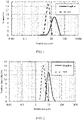
- FIG. 1 is a volume-based particle size distribution curve of the SiO particles and graphite particles
- FIG. 2 is a number-based particle size distribution curve of the SiO particles and graphite particles.
- the performance evaluation results of the selected negative electrode material and the resulting full battery in this embodiment are shown in Table 1 (the gram capacity is a capacity obtained when the delithiation cut-off voltage is 2.0 V, the same applies below) and Table 1-1.
- Table 1 For differences from Embodiment 1, refer to Table 1.
- Table 1 D n50 /D v50 D V50 ( ⁇ m) Specific surface area (m 2 ⁇ g -1 ) Gram capacity* (mAh ⁇ g -1 ) First-cycle Coulombic efficiency (%) Matching graphite particles 0.2 13.6 1.18 355 93.6 Silicon-based particles in Embodiment 1 0.3 5.3 1.32 1679 68.4 Silicon-based particles in Embodiment 2 0.5 5.3 1.27 1681 68.9 Silicon-based particles in Embodiment 3 0.8 5.3 1.24 1678 69.3 Silicon-based particles in Comparative Embodiment 1 0.1 5.3 1.45 1665 67.9 Table 1-1 400 th -cycle capacity retention rate cycled at 25 °C 200 th -cycle capacity retention rate cycled at 45 °C 400 th -cycle deformation rate cycled at 25 °C 200 th
- Embodiments 1 to 3 satisfy: the D n50 /D v50 ratio of the graphite particles falls within the range of 0.1 to 0.65, the D n50 /D v50 ratio of the silicon-based particles falls within the range of 0.3 to 0.85, and the D n50 /D v50 ratio of the silicon-based particles is greater than the D n50 /D v50 ratio of the graphite particles.
- the performance of the finally obtained full battery is excellent.
- the performance of the full battery obtained in Comparative Embodiment 1 that does not satisfy the foregoing conditions is significantly inferior to that in embodiments hereof.
- FIG. 5 shows deformation resistance performance of Embodiment 3 versus Comparative Embodiment 1.
- Embodiments 4 to 6 satisfy: the D n50 /D v50 ratio of the graphite particles falls within the range of 0.1 to 0.65, the D n50 /D v50 ratio of the silicon-based particles falls within the range of 0.3 to 0.85, and the D n50 /D v50 ratio of the silicon-based particles is greater than the D n50 /D v50 ratio of the graphite particles.
- the performance of the finally obtained full battery is excellent.
- the performance of the full battery obtained in Comparative Embodiments 2 to 3 that do not satisfy the foregoing conditions is significantly inferior to that in embodiments hereof.
- the D n50 /D v50 ratio represents the degree of concentration of particle distribution. The closer the value of the ratio is to 1, the more concentrated the particle size distribution.
- the battery performance is relatively high. That is because lithiation-induced expansion of the silicon-based material is much larger than that of the graphite material.
- the average particle diameter of the silicon-based particles is set to be smaller than that of graphite particles.
- the distribution of the silicon-based particles is more concentrated than the distribution of the graphite particles. This helps to disperse the silicon-based particles into voids between the packed graphite particles, and minimizes the impact caused by the expansion of the silicon-based material onto the overall expansion of the electrode plate.
- a higher D n50 /D v50 ratio of SiO particles can improve the cycle performance and deformation resistance performance of the battery. That is because when the distribution of the silicon-based particles is poorly concentrated, numerous oversized or undersized particles exist.
- Undersized particles increase the area of contacting the electrolytic solution, give rise to a larger amount of SEI layers, and consume the electrolytic solution and the limited reversible lithium in the battery.
- the oversized particles increase the stress generated during the lithiation-induced expansion, cause the particles to rupture, make the fresh interface exposed to react with the electrolytic solution, consume reversible lithium, and deteriorate the cycle performance.
- the large particles increase diffusion paths of lithium ions, aggravate concentration polarization, and impair the rate performance of the battery.
- Table 3 Average sphericity I 1330 /I 1580 ratio Specific surface area (m 2 ⁇ g -1 ) Gram capacity* (mAh ⁇ g -1 ) First-cycle Coulombic efficiency (%) Matching graphite particles 0.68 0.4 1.06 355 93.1 SiO particles in Embodiment 7 0.92 1.6 1.28 1682 69.4 SiO particles in Embodiment 8 0.89 1.6 1.31 1672 68.7 SiO particles in Embodiment 9 0.85 1.6 1.28 1687 68.9 SiO particles in Comparative Embodiment 4 0.75 1.6 1.35 1684 69.2 Table 3-1 400 th -cycle capacity retention rate cycled at 25 °C 200 th -cycle capacity retention rate cycled at 45 °C 400 th -cycle deformation rate cycled at 25 °C 200 th -cycle deformation rate
- Embodiments 7 to 9 versus Comparative Embodiment 4 shown in Table 3 and Table 3-1 As can be seen from Embodiments 7 to 9 versus Comparative Embodiment 4 shown in Table 3 and Table 3-1, as the average sphericity of SiO particles decreases, the capacity retention rate of the battery declines, and the deformation rate increases. That is because the SiO particles expand enormously during lithiation. The stress generated by the expansion ruptures the surface of the particles. Consequently, a fresh interface is exposed and contacts the electrolytic solution, thereby generating more SEI layers, and accelerating corrosion of the SiO particles by the electrolytic solution.
- the SiO particles with a relatively high sphericity can effectively and evenly disperse the stress generated by the lithiation-induced expansion, alleviate formation of surface cracks, reduce the SEI layers packed on the surface, and decrease the corrosion speed.
- I 1330 and I 1580 are the peak intensity at 1330 cm -1 and 1580 cm -1 , respectively, in the Raman scattering peak of the corresponding graphite particle or SiO particle.
- the performance evaluation results of the selected negative electrode material and the resulting full battery in these embodiments are shown in Table 4 and Table 4-1.
- Table 4 Average sphericity I 1330 /I 1580 ratio Specific surface area (m 2 ⁇ g -1 ) Gram capacity* (mAh ⁇ g -1 ) First -cycle Coulombic efficiency (%) Matching SiO particles 0.92 1.6 1.28 1682 69.4 Graphite particles in Embodiment 7 0.68 0.4 1.26 355 93.1 Graphite particles in Embodiment 10 0.62 0.4 1.37 355 932 Graphite particles in Embodiment 11 0.74 0.4 1.21 355 929 Graphite particles in Comparative Embodiment 5 0.84 0.4 1.38 355 92.2 Graphite particles in Comparative Embodiment 6 0.55 0.4 1.31 355 923 Table 4-1 400 th -cycle capacity retention rate cycled at 25 °C 200 th -cycle capacity retention rate cycled at 45 °C
- both deficient sphericity and excessive sphericity of the graphite particles affect electrochemical performance of the battery.
- the silicon-based particles are unable to fill in the pores between the graphite particles, thereby increasing the shift of the SiO x particles caused during expansion and shrinkage of the material, aggravating deformation of the battery, and resulting in capacity fading.
- the sphericity of the graphite is deficient, anisotropy increases, thereby slowing down the intercalation speed of lithium ions, and affecting the kinetics of the battery.
- Embodiment 7 For differences from Embodiment 7, refer to Table 5, in which I1 is a maximum intensity value in an X-ray diffractogram of the corresponding SiO particles when 2 ⁇ falls within a range of 20.5° to 21.5°, and I2 is the maximum intensity value in the X-ray diffractogram of the corresponding SiO particles when 2 ⁇ falls within a range of 28.0° to 29.0°.
- Table 5 The performance evaluation results of the selected negative electrode material and the resulting full battery in these embodiments are shown in Table 5 and Table 5-1.
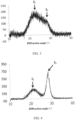
- FIG. 3 and FIG. 4 show an X-ray diffractogram of the SiO particles according to Embodiments 12 and 14 respectively.
- Embodiments 7, 12, 13, and 14 versus Comparative Embodiment 7 shown in Table 5 and Table 5-1 With the increase of the I2/I1 ratio, the cycle performance keeps declining, the expansion increases, and the rate performance deteriorates.
- the I2/I1 ratio value reflects the impact caused by disproportionation onto the SiO particles. When the value is higher, the size of nano-silicon crystal grains caused by disproportionation inside the SiO particles is larger. Consequently, the stress in a local region of the active layer increases sharply during lithiation, thereby disrupting the structure of the material in the negative electrode plate during cycles. In addition, the resulting nanocrystalline distribution affects the capability of grain boundary diffusion during ion diffusion.
- Embodiments 15 to 17 and Comparative Embodiments 8 to 9 shown in Table 6 and Table 6-1 when the D/G ratio, that is, an intensity ratio of the Raman scattering peak of the graphite particles, is deficient, the degree of surface order is high of the particles, the material can hardly be infiltrated by the electrolytic solution, and the kinetic properties of the battery deteriorate.
- the D/G ratio of the Raman scattering peak of the graphite particles is excessive, the coating on the surface of the graphite particles is excessively thick and contains a large amount of defective amorphous carbon coating, thereby decreasing the first-cycle Coulombic efficiency and the gram capacity of the material.
- the excessively thick amorphous carbon layer consumes some lithium ions, and leads to acceleration of capacity fading.
- a difference from Embodiment 1 is that a coating exists on the surface of the SiO particles.
- Table 7 shows the type and content of metal elements and the carbon content in the coating (in which "-" indicates that the corresponding substance is not added).
- the thickness of the coating is 10 nm, and the mass of the coating is 0.425% of the total mass of the SiO particles.
- Table 7 Type of metal element Content of metal element (wt%) Carbon content (wt%) Specific surface area (m 2 /g) Gram capacity* (mAh ⁇ g -1 ) First -cycle Coulombic efficiency (%) SiO particles in Embodiment 1 - - - 1.32 1679 68.4 SiO particles in Embodiment 18 Al 0.125 0.300 1.45 1672 68.3 SiO particles in Embodiment 19 Ti 0.125 0.300 1.44 1676 74.0 SiO particles in Embodiment 20 Al+Ti 0.125 0.300 1.53 1681 70.2 SiO particles in Embodiment 21 - - 0.300 1.39 1692 742 Table 7-1 400 th -cycle capacity retention rate cycled at 25 °C 200 th -cycle capacity retention rate cycled at 45 °C 400 th -cycle deformation rate cycled at 25 °C 200
- the coating existent on the surface of SiO particles further improves the cycle performance and/or rate performance and deformation resistance of the lithium-ion battery.
- the carbon coating formed by aluminum and carbon can further improve the cycle performance and/or rate performance and deformation resistance of the lithium-ion battery.
Landscapes
- Chemical & Material Sciences (AREA)
- Chemical Kinetics & Catalysis (AREA)
- General Chemical & Material Sciences (AREA)
- Electrochemistry (AREA)
- Engineering & Computer Science (AREA)
- Materials Engineering (AREA)
- Inorganic Chemistry (AREA)
- Organic Chemistry (AREA)
- Composite Materials (AREA)
- Manufacturing & Machinery (AREA)
- Geology (AREA)
- General Life Sciences & Earth Sciences (AREA)
- Life Sciences & Earth Sciences (AREA)
- Battery Electrode And Active Subsutance (AREA)
- Secondary Cells (AREA)
Abstract
Description
- The present invention relates to the technical field of batteries, in particular, to the technical field of lithium-ion batteries, and specifically, to a negative electrode material, a negative electrode plate coated with the negative electrode material, an electrochemical device containing the negative electrode plate, and an electronic device.
- As a next-generation high-capacity negative electrode material, a silicon-based material can significantly increase an energy density of a battery. Especially, a silicon-oxygen material in the silicon-based materials possesses the advantages such as a high specific capacity (2400 mAh/g), abundant raw material sources, and environmental friendliness. However, a hybrid negative electrode made of the silicon-oxygen material incurs a relatively high degree of volume expansion and shrinkage during deintercalation and intercalation. This makes the silicon-oxygen material particles keep migrating, increases a porosity of the negative electrode plate, leads to failure of connection between active materials in the electrode plate, increases a capacity fading speed and a deformation rate of the battery, and severely impairs the effect of the material in practical applications.
- Existing technologies for improving battery cycle performance and reducing battery deformation mainly focus on improving the structure and interface of silicon-based materials, and achieve good improvement effects. However, the practice of simply improving the silicon-based material but without considering a reasonable conjunction between the graphite material in the hybrid negative electrode and a morphology and a particle diameter is unable to fully exert electrical performance of the negative electrode. Researches show that the negative electrodes prepared from the graphite particles of different morphologies and diameters in conjunction with the silicon-based material differ greatly in the distribution of the silicon-based material, porosity of the electrode plate, distribution of pores, and the like. Such factors are crucial to cycle performance and deformation of the battery.
- In view of the problems in the prior art, one of objectives of the present invention is to provide a negative electrode material to improve cycle performance and a deformation rate of a battery by means of reasonable matching of morphology and particle size between a silicon-based material and a graphite material. In addition, on the basis of the reasonable matching between the silicon-based material and the graphite material, characteristics such as particle size distribution, sphericity, and XRD features of the silicon-based particles and graphite particles are further defined to obtain a negative electrode material of higher performance.
- Another objective of the present invention is to provide a negative electrode plate containing the foregoing negative electrode material, a method for preparing the negative electrode plate, a lithium-ion secondary battery, a method for preparing the lithium-ion secondary battery, an electrochemical device, and an electronic device.
- For such purposes, the present invention provides a negative electrode material. The negative electrode material contains silicon-based particles and graphite particles. In a case that a Dn50/Dv50 ratio of the graphite particles is A and a Dn50/Dv50 ratio of the silicon-based particles is B, the following conditional expressions (1) to (3) are satisfied:



- Dv50 is a particle diameter of particles measured when a cumulative volume fraction in a volume-based distribution reaches 50%; and Dn50 is a particle diameter of particles measured when a cumulative number fraction in a number-based distribution reaches 50%.
- Dn50/Dv50 is a ratio of Dn50 to Dv50 measured by a laser scattering particle size analyzer. The closer the value is to 1, the more concentrated the particle size distribution. In the negative electrode material according to the present invention, when the concentration degree of the graphite particles is lower than the concentration degree of the silicon-based particles, the battery exhibits higher cycle performance and a lower deformation rate. That is because lithiation-induced expansion of the silicon-based material is much larger than that of the graphite material. In order to reduce a stress generated during the expansion, an average particle diameter of the silicon-based particles is set to be smaller than an average particle diameter of the graphite particles. In a case that an active material on an electrode plate is compounded of the silicon-based particles and the graphite particles, the distribution of the silicon-based particles is more concentrated than the distribution of the graphite particles. This helps to disperse the silicon-based particles into voids between the packed graphite particles, and minimizes the impact caused by the expansion of the silicon-based material onto the overall expansion of the electrode plate, thereby improving the cycle performance and deformation rate of the battery.
- Specifically, when the Dn50/Dv50 ratio of the graphite particles falls within the range of 0.1 to 0.65, electrical performance of the battery is relatively high. When the Dn50/Dv50 ratio of the graphite particles is less than 0.1, there are excessive fine particles and large particles in the graphite particles. The excessive fine particles lead to an excessive specific surface area of the material, and reduce the first-cycle Coulombic efficiency. The excessive large particles increase a transmission distance of lithium ions, aggravate the deformation of the battery, and deteriorate rate performance of the battery. When the Dn50/Dv50 ratio of the graphite particles is greater than 0.65, the particle size distribution of the graphite particles is excessively concentrated, thereby being adverse to packing the graphite particles in the negative electrode plate, and increasing the processing cost significantly.
- Specifically, when the Dn50/Dv50 ratio of the silicon-based particles falls within the range of 0.3 to 0.85, the electrical performance of the battery is relatively high. When the Dn50/Dv50 ratio of the silicon-based particles is less than 0.3, the distribution of the silicon-based particles is lowly concentrated, and numerous oversized or undersized silicon-based particles exist. The excessive number of the undersized silicon-based particles increases the area of contacting the electrolytic solution, generates a larger amount of solid electrolyte interphase film (SEI film), and consumes the limited reversible lithium in the battery. The oversized silicon-based particles increase the stress generated during the lithiation-induced expansion, cause the silicon-based particles to rupture, make a fresh interface exposed to react with the electrolytic solution, consume reversible lithium, and deteriorate the cycle performance. In addition, the oversized silicon-based particles increase diffusion paths of lithium ions, aggravate concentration polarization, and affect the rate performance of the battery. When the Dn50/Dv50 ratio of the silicon-based particles is greater than 0.85, mass production is impracticable due to a low yield rate and high cost.
- For the negative electrode material according to the present invention, preferably, in a case that an average sphericity of the graphite particles is C and an average sphericity of the silicon-based particles is D, the following conditional expression (4) is satisfied:

- For the negative electrode material according to the present invention, preferably, an average sphericity D of the silicon-based particles is greater than or equal to 0.8.
- For the negative electrode material according to the present invention, preferably, an average sphericity C of the graphite particles falls between 0.55 and 0.75, that is, 0.55 ≤ C ≤ 0.75.
- For the negative electrode material according to the present invention, preferably, a general formula of the silicon-based particles is: SiOxCyMz (I), where 0 ≤ x ≤ 2, 0 ≤ y < 1, 0 ≤ z ≤ 0.5, and M includes at least one of lithium, magnesium, titanium, or aluminum.
- For the negative electrode material according to the present invention, preferably, a carbon coating, a polymer coating, or a composite coating of carbon and polymer exists on a surface of the silicon-based particles.
- For the negative electrode material according to the present invention, preferably, a carbon coating, a polymer coating, or a composite coating of carbon and polymer exists on a surface of the graphite particles.
- For the negative electrode material according to the present invention, preferably, the carbon coating is formed by at least one of crystalline carbon, carbon nanotubes, carbon nanoparticles, vapor grown carbon fibers, or graphene. Further preferably, the carbon coating further contains a metal, and the metal includes at least one of aluminum or titanium.
- For the negative electrode material according to the present invention, preferably, the polymer coating is formed by at least one of polyvinylidene difluoride or a derivative thereof, carboxymethyl cellulose or a derivative thereof, polyvinylpyrrolidone or a derivative thereof, polyacrylic acid or a derivative thereof, or polystyrene butadiene rubber. The derivative means a relatively complex product derived by substituting a hydrogen atom or atomic group in a simple compound by another atom or atomic group.
- For the negative electrode material according to the present invention, preferably, a thickness of the coating of the silicon-based particles is 0.5 to 50 nm.
- For the negative electrode material according to the present invention, preferably, a mass of the coating of the silicon-based particles is 0.1% to 10% of a total mass of the silicon-based particles.
- For the negative electrode material according to the present invention, preferably, a particle diameter range of the silicon-based particles is 0.01 to 50 µm.
- For the negative electrode material according to the present invention, preferably, in an X-ray diffractogram of the silicon-based particles, in a case that a maximum intensity value when 2θ falls within a range of 20.5° to 21.5° is I1 and the maximum intensity value when 2θ falls within a range of 28.0° to 29.0° is I2, it is satisfied that I2/I1 is less than or equal to 10, and preferably I2/I1 is less than or equal to 1.
- For the negative electrode material according to the present invention, preferably, a specific surface area of the silicon-based particles is 0.1 to 50 m2/g, and preferably 0.1 to 5 m2/g.
- For the negative electrode material according to the present invention, preferably, in a Raman scattering peak of the graphite particles, in a case that a peak intensity at 1330 cm-1 is I1330 and the peak intensity at 1580 cm-1 is I1580, the following conditional expression (5) is satisfied:

- For the negative electrode material according to the present invention, preferably, the graphite particles include a secondary particle, and a weight percent of the secondary particle is at least 70 wt% of a total weight of the graphite particles.
- For the negative electrode material according to the present invention, preferably, in an X-ray diffraction peak of the graphite particles, in a case that a peak intensity ratio between a (004) peak and a (110) peak is an orientation index (OI) value, the following conditional expression (6) is satisfied:

- For such purposes, the present invention further provides a negative electrode plate, including the negative electrode material described above.
- For such purposes, the present invention further provides a method for preparing a negative electrode plate. The method includes the following steps:
- (a) mixing the foregoing negative electrode material with a conductive agent to obtain a first mixture;
- (b) mixing the first mixture with a binder in a solvent to obtain a first mixed slurry; and
- (c) coating a current collector with the first mixed slurry, and performing drying, cold calendering, and slitting to obtain a negative electrode plate.
- In the preparation method according to the present invention, preferably, in the first mixture, the content of silicon-based particles is 5 wt% to 30 wt %, the content of the conductive agent is 0.5 wt% to 5 wt %, and the remainder is graphite particles.
- In the preparation method according to the present invention, preferably, the conductive agent includes at least one of nanoscale conductive carbon black, carbon nanotubes, carbon fibers, flake graphite, graphene, or Ketjen black.
- In the preparation method according to the present invention, preferably, the carbon nanotubes include single-walled carbon nanotubes, multi-walled carbon nanotubes, or a combination thereof; and the carbon fibers include vapor-grown carbon fibers, carbon nanofibers, or a combination of thereof.
- In the preparation method according to the present invention, preferably, the weight ratio between the first mixture and the binder is 100: (1 to 6).
- In the preparation method according to the present invention, preferably, the binder includes at least one of polyacrylic acid, polyacrylic acid sodium, polyacrylic acid potassium, polyacrylic acid lithium, polyimide, polyvinyl alcohol, carboxymethyl cellulose, sodium carboxymethyl cellulose, polyimide, polyamide imide, styrene butadiene rubber, or polyvinylidene fluoride.
- In the preparation method according to the present invention, preferably, the solvent includes at least one of deionized water or N-methyl-pyrrolidone.
- In the preparation method according to the present invention, preferably, the current collector is prepared from at least one of copper, copper alloy, nickel, or nickel alloy.
- In the preparation method according to the present invention, preferably, a thickness of an active layer of the negative electrode plate is 50 to 200 µm, a single-side compacted density of the active layer is 1.4 to 1.9 g/cm3, and a porosity of the active layer is 15% to 35%.
- For such purposes, the present invention further provides a lithium-ion secondary battery. The battery includes a positive electrode plate, the foregoing negative electrode plate, a separator, and an electrolytic solution.
- For such purposes, the present invention further provides a method for preparing a lithium-ion secondary battery. The method includes the following steps:
- S1. mixing a positive electrode material, a conductive agent, a binder, and a solvent, and stirring to make a first positive mixed slurry;
- S2. coating a current collector with the first positive mixed slurry obtained in step S1, and performing drying, cold calendering, and slitting to obtain a positive electrode plate; and
- S3. winding the positive electrode plate obtained in step S2, the foregoing negative electrode plate, and a separator to obtain a bare cell; and
- S4. putting the bare cell obtained in step S3 into a packaging bag, performing drying, injecting an electrolytic solution, and performing sealing and chemical formation to obtain a lithium-ion secondary battery.
- In the preparation method according to the present invention, preferably, the positive electrode material includes lithium composite oxide. The lithium composite oxide includes a transition metal. The transition metal includes at least one of nickel, manganese, cobalt, or iron.
- In the preparation method according to the present invention, preferably, the conductive agent in
step S 1 includes at least one of nanoscale conductive carbon black, carbon nanotubes, carbon fibers, flake graphite, graphene, or Ketjen black. - In the preparation method according to the present invention, preferably, the separator is prepared from at least one of glass fiber, polyester, polyethylene, polypropylene, or polytetrafluoroethylene. The separator is a porous polymer film with a pore diameter of 0.01 µm to 1 µm. The thickness of the separator is 5 µm to 500 µm.
- In the preparation method according to the present invention, preferably, the electrolytic solution includes an organic solvent, a lithium salt, and an additive. The lithium salt is an organic lithium salt and/or an inorganic lithium salt.
- In the preparation method according to the present invention, preferably, the organic solvent includes at least one of ethylene carbonate, propylene carbonate, diethyl carbonate, ethyl methyl carbonate, dimethyl carbonate, propylene carbonate, or ethyl propionate.
- The preparation method according the present invention, preferably, the organic lithium salt includes at least one of lithium hexafluorophosphate, lithium tetrafluoroborate, lithium difluorophosphate, lithium bis(trifluoromethanesulfonyl)imide, lithium bis(fluorosulfonyl)imide, lithium bis(oxalato)borate, or lithium difluoro(oxalato)borate.
- For such purposes, the present invention further provides an electrochemical device. The electrochemical device includes the foregoing negative electrode plate.
- For such purposes, the present invention further provides an electronic device. The electronic device includes the foregoing lithium-ion secondary battery and/or electrochemical device.
- Beneficial effects of the present invention are as follows:
First, by reasonably matching the morphology and particle size distribution between the silicon-based particles and the graphite particles in the negative electrode material, the overall expansion stress of the negative electrode material can be dispersed uniformly. In this way, the silicon-based particles fill in the voids between the graphite particles, and the two types of particles mesh together like gears, thereby increasing the compacted density of the negative electrode material and suppressing a shift caused by the expansion of the silicon-based particles. - Second, on the basis of reasonably matching the morphology and particle size distribution between the silicon-based particles and the graphite particles, the present invention further defines: (1) the size of the silicon-based particles in the negative electrode material, so that a grain size is gradually reduced to an amorphous state; (2) a surface structure of the graphite particles; and (3) existence of a coating on the surface of the silicon-based particles and/or graphite particles. Finally, a negative electrode material with significantly improved cycle performance and rate performance is obtained. In addition, a negative electrode plate prepared from the negative electrode material can reduce the deformation rate of the battery during cycles.
-
-
FIG. 1 is a volume-based particle size distribution curve of SiO particles and graphite particles according toEmbodiment 1 of the present invention; -
FIG. 2 is a number-based particle size distribution curve of SiO particles and graphite particles according toEmbodiment 1 of the present invention; -
FIG. 3 is an X-ray diffractogram according toEmbodiment 12 of the present invention; -
FIG. 4 is an X-ray diffractogram according toEmbodiment 14 of the present invention; and -
FIG. 5 shows deformation resistance performance ofEmbodiment 3 of the present invention versusComparative Embodiment 1. - Embodiments of the present invention are described in detail below. The embodiments are implemented based on the technical solution of the present invention, and include detailed manners and processes of implementation, but the protection scope of the present invention is not limited to the following embodiments. An experimental method described in the following embodiments without specifying conditions are generally performed under conventional conditions.
- The present invention provides a negative electrode material. The negative electrode material contains silicon-based particles and graphite particles. In a case that a Dn50/Dv50 ratio of the graphite particles is A and a Dn50/Dv50 ratio of the silicon-based particles is B, the following conditional expressions (1) to (3) are satisfied:


- Dv50 is a particle diameter of particles measured when a cumulative volume fraction in a volume-based distribution reaches 50%; and Dn50 is a particle diameter of particles measured when a cumulative number fraction in a number-based distribution reaches 50%.
- Dn50/Dv50 is a ratio of Dn50 to Dv50 measured by a laser scattering particle size analyzer. The closer the value is to 1, the more concentrated the particle size distribution. In the negative electrode material according to the present invention, when the concentration degree of the graphite particles is lower than the concentration degree of the silicon-based particles, the battery exhibits higher cycle performance and a lower deformation rate. That is because lithiation-induced expansion of the silicon-based material is much larger than that of the graphite material. In order to reduce a stress generated during the expansion, an average particle diameter of the silicon-based particles is set to be smaller than an average particle diameter of the graphite particles. In a case that an active material on an electrode plate is compounded of the silicon-based particles and the graphite particles, the distribution of the silicon-based particles is more concentrated than the distribution of the graphite particles. This helps to disperse the silicon-based particles into voids between the packed graphite particles, and minimizes the impact caused by the expansion of the silicon-based material onto the overall expansion of the electrode plate, thereby improving the cycle performance and deformation rate of the battery.
- Specifically, when the Dn50/Dv50 ratio of the graphite particles falls within the range of 0.1 to 0.65, the electrical performance of the battery is optimal. When the Dn50/Dv50 ratio of the graphite particles is less than 0.1, there are excessive fine particles and large particles in the graphite particles. The excessive fine particles lead to an excessive specific surface area of the material, and reduce the first-cycle Coulombic efficiency. The excessive large particles increase a transmission distance of lithium ions, and deteriorate the deformation rate and rate performance of the battery. In addition, when the Dn50/Dv50 ratio of the graphite particles is greater than 0.65, the particle size distribution of the graphite particles is excessively concentrated, thereby being adverse to packing the graphite particles in the negative electrode plate, and increasing the processing cost significantly.
- Specifically, when the Dn50/Dv50 ratio of the silicon-based particles falls within the range of 0.3 to 0.85, the electrical performance of the battery is optimal. When the Dn50/Dv50 ratio of the silicon-based particles is less than 0.3, the distribution of the silicon-based particles is lowly concentrated, and numerous oversized or undersized silicon-based particles exist. The excessive number of the undersized silicon-based particles increases the area of contacting the electrolytic solution, generates a larger amount of solid electrolyte interphase film (SEI film), and consumes the electrolytic solution and the limited reversible lithium in the battery. The oversized silicon-based particles increase the stress generated during the lithiation-induced expansion, cause the silicon-based particles to rupture, make a fresh interface exposed to react with the electrolytic solution, consume reversible lithium, and deteriorate the cycle performance. In addition, the oversized silicon-based particles increase diffusion paths of lithium ions, aggravate concentration polarization, and affect the rate performance of the battery. When the Dn50/Dv50 ratio of the silicon-based particles is greater than 0.85, mass production is impracticable due to a low yield rate and high cost.
- In some embodiments, in a case that an average sphericity of the graphite particles is C and an average sphericity of the silicon-based particles is D, the following conditional expression (4) is satisfied:

- In some embodiments, the average sphericity D of the silicon-based materials is greater than or equal to 0.8, and is, for example, but not limited to, 0.8, 0.9, or 1.0.
- In some embodiments, the average sphericity C of the graphite particles falls between 0.55 and 0.75, and is, for example, but not limited to, 0.55, 0.65, or 0.75.
- In some embodiments, a general formula of the silicon-based particles is: SiOxCyMz (I), where 0 ≤ x ≤ 2, 0 ≤ y ≤ 1, 0 ≤ z ≤ 0.5, and M includes at least one of lithium, magnesium, titanium, or aluminum. The silicon-based particles are, for example, but not limited to, commercial oxide of silicon SiOx (0.5 < x < 1.5), SiOxCy (0.5 < x < 1.5, 0 < y ≤ 0.1), or SiOxCyLiz (0.5 < x < 1.5, 0 < y ≤ 0.1, 0 ≤ z ≤ 0.1).
- In some embodiments, a carbon coating, a polymer coating, or a composite coating of carbon and polymer exists on a surface of the silicon-based particles.
- In some embodiments, a carbon coating, a polymer coating, or a composite coating of carbon and polymer exists on a surface of the graphite particles.
- In some embodiments, the carbon coating is formed by at least one of crystalline carbon, carbon nanotubes, carbon nanoparticles, vapor grown carbon fibers, or graphene.
- In some embodiments, the polymer coating is formed by at least one of polyvinylidene difluoride or a derivative thereof, carboxymethyl cellulose or a derivative thereof, polyvinylpyrrolidone or a derivative thereof, polyacrylic acid or a derivative thereof, or polystyrene butadiene rubber. The derivative means a relatively complex product derived by substituting a hydrogen atom or atomic group in a simple compound by another atom or atomic group. The derivative is, for example, but not limited to, sodium carboxymethyl cellulose, lithium carboxymethyl cellulose, polyacrylic acid sodium, or polyacrylic acid ammonium.
- In some embodiments, the thickness of the coating of the silicon-based particles is 0.5 to 50 nm, for example, but not limited to, 0.5 nm, 10 nm, 20 nm, 30 nm, 40 nm, or 50 nm.
- In some embodiments, a weight percent of the coating of the silicon-based particles is 0.1% to 10% of a total weight of the silicon-based particles, for example, but not limited to, 0.1%, 3%, 5%, 8%, or 10%.
- In some embodiments, a particle size range of the silicon-based particles is 0.01 to 50 µm, for example, but not limited to, 0.01 µm, 1 µm, 10 µm, 20 µm, 30 µm, 40 µm, or 50 µm.
- In some embodiments, in an X-ray diffractogram of the silicon-based particles, in a case that a maximum intensity value when 2θ falls within a range of 20.5° to 21.5° is I1 and the maximum intensity value when 2θ falls within a range of 28.0° to 29.0° is I2, it is satisfied that I2/I1 is less than or equal to 10, for example, but not limited to, 10, 5, 2, 1, and preferably I2/I1 is less than or equal to 1.
- In some embodiments, the specific surface area of the silicon-based particles is 0.1 to 50 m2/g, for example but not limited to, 0.1 m2/g, 5 m2/g, 10 m2/g, 20 m2/g, 30 m2/g, 40 m2/g, 50 m2/g, and preferably 0.1 to 5 m2/g.
- In some embodiments, in a Raman scattering peak of the graphite particles, in a case that a peak intensity at 1330 cm-1 is I1330 and the peak intensity at 1580 cm-1 is I1580, the following conditional expression (5) is satisfied:

- In some embodiments, the graphite particles include a secondary particle, and a weight percent of the secondary particle is at least 70 wt% of a total weight of the graphite particles. In other embodiments, the graphite particles are formed of secondary particles and primary particles, where the weight percent of the secondary particles is at least 70 wt% and the remainder is primary particles.
- In some embodiments, in an X-ray diffraction peak of the graphite particles, in a case that a peak intensity ratio between a (004) peak and a (110) peak is an orientation index (OI) value, the following conditional expression (6) is satisfied:

- The negative electrode plate according to the present invention is coated with the negative electrode material described above. The coating method may be a conventional electrode material coating method, without being limited herein.
- The present invention further provides a method for preparing a negative electrode plate, including the following steps:
- (a) mixing the foregoing negative electrode material with a conductive agent to obtain a first mixture;
- (b) mixing the first mixture with a binder in a solvent to obtain a first mixed slurry; and
- (c) coating a current collector with the first mixed slurry, and performing drying, cold calendering, and slitting to obtain a negative electrode plate.
- In some embodiments, in the first mixture, the content of silicon-based particles is 5 wt% to 30 wt %, the content of the conductive agent is 0.5 wt% to 5 wt %, and the remainder is graphite particles. In some embodiments, the first mixture includes 5 wt% silicon-based particles, 0.5 wt% conductive agent, and the remainder is graphite particles. In some embodiments, the first mixture includes 30 wt% silicon-based particles, 0.5 wt% conductive agent, and the remainder is graphite particles. In some embodiments, the first mixture includes 30 wt% silicon-based particles, 5 wt% conductive agent, and the remainder is graphite particles. In some embodiments, the first mixture includes 15 wt% silicon-based particles, 2.5 wt% conductive agent, and the remainder is graphite particles.
- In some embodiments, the conductive agent includes at least one of nanoscale conductive carbon black, carbon nanotubes, carbon fibers, or flake graphite, graphene, or Ketjen black.
- In some embodiments, the carbon nanotubes include single-walled carbon nanotubes, multi-walled carbon nanotubes, or a combination thereof; and the carbon fibers include vapor-grown carbon fibers, carbon nanofibers, or a combination of thereof.
- In some embodiments, the weight ratio between the first mixture and the binder is 100: (1 to 6), for example, but not limited to, 100: 1, 100: 6, or 100: 3.
- In some embodiments, the binder includes at least one of polyacrylic acid, polyacrylic acid sodium, polyacrylic acid potassium, polyacrylic acid lithium, polyimide, polyvinyl alcohol, carboxymethyl cellulose, sodium carboxymethyl cellulose, polyimide, polyamide imide, styrene butadiene rubber, or polyvinylidene fluoride.
- In some embodiments, the solvent includes at least one of deionized water and N-methyl-pyrrolidone.
- In some embodiments, the current collector is prepared from at least one of copper, copper alloy, nickel, or nickel alloy.
- In some embodiments, a thickness of an active layer of the negative electrode plate is 50 to 200 µm, a single-side compacted density of the active layer is 1.4 to 1.9 g/cm3, and a porosity of the active layer is 15% to 35%.
- The present invention provides a lithium-ion secondary battery. The battery includes a positive electrode plate, the foregoing negative electrode plate, a separator, and an electrolytic solution.
- The present invention further provides a method for preparing the foregoing lithium-ion secondary battery, including the following steps:
- S1. mixing a positive electrode material, a conductive agent, a binder, and a solvent, and stirring to make a first positive mixed slurry;
- S2. coating a current collector with the first positive mixed slurry obtained in step S1, and performing drying, cold calendering, and slitting to obtain a positive electrode plate; and
- S3. winding the positive electrode plate obtained in step S2, the foregoing negative electrode plate, and a separator to obtain a bare cell; and
- S4. putting the bare cell obtained in step S3 into a packaging bag, performing drying, injecting an electrolytic solution, and performing sealing and chemical formation to obtain a lithium-ion secondary battery.
- In some embodiments, the positive electrode material includes lithium composite oxide. The lithium composite oxide includes a transition metal. The transition metal includes at least one of nickel, manganese, cobalt, or iron.
- In some embodiments, the conductive agent in step S1 includes at least one of nanoscale conductive carbon black, carbon nanotubes, carbon fibers, or flake graphite, graphene, or Ketjen black.
- In some embodiments, the separator is prepared from at least one of glass fiber, polyester, polyethylene, polypropylene, or polytetrafluoroethylene. The separator is a porous polymer film with a pore diameter of 0.01 µm to 1 µm. The thickness of the separator is 5 µm to 500 µm.
- In some embodiments, the electrolytic solution includes an organic solvent, a lithium salt, and an additive. The lithium salt is an organic lithium salt and/or an inorganic lithium salt.
- In some embodiments, the organic solvent includes at least one of ethylene carbonate, propylene carbonate, diethyl carbonate, ethyl methyl carbonate, dimethyl carbonate, propylene carbonate, or ethyl propionate.
- In some embodiments, the organic lithium salt includes at least one of lithium hexafluorophosphate, lithium tetrafluoroborate, lithium difluorophosphate, lithium bis(trifluoromethanesulfonyl)imide, lithium bis(fluorosulfonyl)imide, lithium bis(oxalato)borate, or lithium difluoro(oxalato)borate.
- The electrochemical device according to the present invention includes the foregoing negative electrode plate.
- The electronic device according to the present invention includes the foregoing lithium-ion secondary battery and/or electrochemical device.
-
- 1. Observing micromorphology of powder particles: Observing the micromorphology of the powder by using a scanning electron microscope, and rendering the surface coating of the material, where the test instrument is: OXFORD EDS (X-max-20 mm2) and the acceleration voltage is 15 KV. Adjusting the focal length, and observing the image at a high magnification of 50 K or above, and at a low magnification of 500 to 2000 that is mainly used for observing agglomeration of particles.
- 2. Sphericity test: Capturing images of a given number of (more than 5000) dispersed particles, and processing the images by using a Malvern automatic image particle size analyzer. Analyzing the microstructure and morphology of the particles accurately by means of a morphologically directed Raman spectroscopy (MDRS) to obtain a longest diameter and a shortest diameter of each particle, and calculating a ratio of the smallest diameter to the largest diameter to obtain the sphericity of the particle.
- 3. Specific surface area test: Measuring a quantity of a gas adsorbed on the surface of a solid under different relative pressures and at a constant low temperature, and then determining the monolayer adsorbed gas quantity of the specimen based on the Brunauer-Emmett-Teller (BET) adsorption theory, and calculating a specific surface area of the solid from the BET equation.
During the test, weighing out 1.5 to 3.5 grams of powder specimen, loading the specimen into a specimen tube of TriStar II 3020, degassing at 200 °C for 120 minutes, and then testing the specimen. - 4. Particle size test (the size of a particle is referred to as a "particle size", also known as "particle diameter" or "diameter"): Adding approximately 0.02 gram of powder specimen into a 50 ml clean beaker, adding approximately 20 ml of deionized water, and then adding a few drops of 1% surfactant dropwise to make the powder fully dispersed in the water. Ultrasonically cleaning the specimen in a 120 W ultrasonic cleaning machine for 5 minutes. Measuring the particle size distribution by using a MasterSizer 2000. Using a laser scattering particle size analyzer to obtain: the diameter of a particle measured when the cumulative volume fraction of measured particles reaches 50% of the total volume of all specimen particles in a volume-based particle size distribution, and the diameter of a particle measured when the cumulative number fraction of measured particles reaches 50% of the total number of all specimen particles in a number-based particle size distribution.
- 5. Measuring a carbon content: Heating the specimen in a high-frequency furnace under an oxygen-rich condition to burn the specimen so that carbon and sulfur are oxidized into a gas of carbon dioxide and sulfur dioxide respectively. Treating the gas, and passing the gas into a corresponding absorption pool to absorb infrared radiation, and then converting the absorbed infrared light into corresponding signals by using a detector. Converting the signals, which are sampled and linearly corrected in a computer, into a value proportional to the concentration of the carbon dioxide and the sulfur dioxide. Summing all such values obtained in the entire analysis process. Upon completion of the analysis, dividing the sum by the weight value in the computer, and then multiplying by a correction coefficient, and deducting blank values to obtain weight percentages of carbon and sulfur in the specimen. Testing the specimen by using a high-frequency infrared carbon-sulfur analyzer (HCS-140, manufactured by Shanghai Dekai Instrument Co., Ltd.).
- 6. Metal element content test: Weighing out a given amount of the material to serve as a specimen, adding a given amount of concentrated nitric acid into the specimen to digest the specimen into a solution by means of microwave. Filtering the solution to obtain a filtrate and a filter residue. Washing the residue for several times, and bringing the filtrate to a predetermined volume. Measuring the plasma intensity of a metal element in the solution by using an inductively coupled plasma optical emission spectroscopy (ICP-OES) instrument. Calculating the metal content in the solution according to a standard curve of the measured metal, and then calculating the weight percent of the metal element in the material.
- 7. XRD test: Weighing out 1.0 to 2.0 grams of the material to serve as a specimen. Pouring the specimen into a groove of a glass specimen rack. Compacting and flattening the specimen by using a glass sheet. Performing the XRD test by using an X-ray diffractometer (Bruker-D8) based on the standard JJS K 0131-1996 General Rules for X-Ray Diffractometry. Setting a test voltage to 40 kV, setting a current to 30 mA, setting a scanning angle to a value within a range of 10° to 85°, setting a scanning step length to 0.0167°, and setting a time of 0.24 s for each step length. Calculating a peak intensity ratio between the (004) peak and the (110) peak in the XRD diffraction peaks of graphite to obtain an OI value of the graphite.
- 8. Method for testing a button battery containing a powder material: Mixing the negative electrode material obtained in an embodiment, conductive carbon black, and a binder polyacrylic acid (PAA) at a weight ratio of 80: 10: 10 in deionized water. Stirring the mixture evenly to form a slurry. Coating a foil with the slurry for a thickness of 100 µm by using a scraper. Drying the foil in a vacuum oven at 85 °C for 12 hours. Cutting the foil into discs of 1 cm in diameter in a dry environment by using a stamping machine. Using a metal lithium sheet as a counter electrode in a glovebox. Using a Ceglard composite film as a separator. Injecting an electrolytic solution, and performing packaging to form a button battery. Performing a charge-and-discharge test on the battery by use of a LAND series battery test system to check the charge capacity and discharge capacity of the battery.
- Discharging the battery at a current of 0.05 C until the voltage reaches 0.005 V, leaving the battery to stand for 5 minutes, and then discharging the battery at a current of 50 µA until the voltage reaches 0.005 V. Leaving the battery to stand for 5 minutes, and then discharging the battery at a current of 10 µA until the voltage reaches 0.005 V, so as to obtain a first-cycle lithiation capacity of the material. Charging the battery at a current of 0.1 C until the voltage reaches 2 V, so as to obtain a first-cycle delithiation capacity. Finally, calculating a ratio of the first-cycle delithiation capacity to the first-cycle lithiation capacity to obtain the first-cycle Coulombic efficiency of the material.
-
- 1. Cycle performance test: Charging the battery at a constant current of 0.7 C at 25 °C and 45 °C separately until the voltage reaches 4.4 V. Charging the battery at a constant voltage until the current reaches 0.025 C. Leaving the battery to stand for 5 minutes, and then discharging the battery at a current of 0.5 C until the voltage reaches 3.0 V. Using the capacity obtained in this step as an initial capacity. Performing a cycle test in which the battery is charged at 0.7 C and discharged at 0.5 C. Comparing the capacity obtained in each step with the initial capacity to obtain a plurality of ratios. Plotting a capacity fading curve by using the ratios. Performing charge-and-discharge cycles on the battery at 25 °C until the capacity retention rate drops to 90%, and recording the number of cycles at this time as an indicator of the room-temperature cycle performance of the battery. Performing charge-and-discharge cycles at 45 °C until the capacity retention rate drops to 80%, and recording the number of cycles at this time as an indicator of the high-temperature cycle performance of the battery. Comparing the two numbers of cycles to obtain the cycle performance of the material.
- 2. Discharge rate test: Discharging the battery at a rate of 0.2 C under a temperature of 25 °C until the voltage reaches 3.0 V, and leaving the battery to stand for 5 minutes. Charging the battery at 0.5 C until the voltage reaches 4.45 V, and charging the battery at a constant voltage until the current reaches 0.05 C, and then leaving the battery to stand for 5 minutes. Adjusting the discharge rate and performing discharge tests at 0.2 C, 0.5 C, 1 C, 1.5 C, and 2.0 C separately to obtain corresponding discharge capacities. Calculating a ratio of the capacity of the battery discharged at each C-rate to the capacity of the battery discharged at 0.2 C. Evaluating the rate performance by comparing the ratio under 2 C and 0.2 C.
- 3. Testing an expansion rate of a fully charged battery: Measuring a thickness of a half-charged fresh battery by using a spiral micrometer (a full battery charged until the voltage reaches a range of 3.7 V to 4.0 V is defined as a half-charged full battery, and such a charging process is referred to as half charge). When the battery reaches a fully charged state at the end of the 400th cycle, measuring the thickness of the battery at this time by using the spiral micrometer. Comparing the thickness at this time with the thickness of the fresh battery that is initially half charged, so as to obtain the expansion rate of the fully charged battery at this time.
-
- (1) Commercial oxide of silicon (SiO) particles (also referred to as SiOx, 0.5 < x < 1.5, Dv50 = 5.3 µm), B = Dn50/Dv50 = 0.3; particle size range: 0.01 to 20 µm; average sphericity: 0.85; specific surface area: 1.32 m2.g-1.
- (2) Graphite particles (formed of secondary particles and primary particles, where the weight percent of the secondary particles is 80 wt%, the remainder is the primary particles); Dv50 = 13.6, A = Dn50/Dv50 = 0.2; and the average sphericity is 0.65.
-
FIG. 1 is a volume-based particle size distribution curve of the SiO particles and graphite particles, andFIG. 2 is a number-based particle size distribution curve of the SiO particles and graphite particles. - A method for preparing a negative electrode plate according to this embodiment includes the following steps:
- (a) Mixing the SiO particles and graphite particles as the negative electrode material with nanoscale conductive carbon black as a conductive agent to obtain a first mixture, in which the weight percent of SiO particles is 15 wt%, the weight percent of the conductive agent is 2.5 wt%, and the remainder is graphite particles.
- (b) Mixing the first mixture with polyacrylic acid as a binder in a deionized water solvent to obtain a first mixed slurry, in which the weight ratio between the first mixture and the binder is 100: 4.
- (c) Coating a current collector nickel foil with the first mixed slurry, and performing drying, cold calendering, and slitting to obtain a negative electrode plate, in which the thickness of the active layer is 150 µm, a single-side compacted density of the active layer is 1.7 g/cm3, and the porosity of the active layer is 25%.
- A method for preparing a lithium-ion secondary battery according to this embodiment includes the following steps:
- (1) Preparing a positive electrode plate: Mixing LiCoO2 as a positive active material, nanoscale conductive carbon black, and polyvinylidene difluoride (PVDF) as a binder at a weight ratio of 96.7: 1.7: 1.6 in an N-methyl-pyrrolidone solvent system, and stirring evenly to form a slurry. Coating an aluminum foil with the slurry, and then performing drying and cold calendering, and slitting to obtain a positive electrode plate.
- (2) Winding the positive electrode plate obtained in step (1), the foregoing negative electrode plate, and polyethylene (PE) porous polymer film as a separator (the pore diameter of the film is 0.01 µm to 1 µm; and the thickness of the separator is 200 µm). Winding the plates and separator to obtain a bare cell.
- (3) Preparing an electrolytic solution: Adding lithium hexafluorophosphate (LiPF6) into a solvent in a dry argon atmosphere, where the solvent is a mixture of propylene carbonate (PC), ethylene carbonate (EC), and diethyl carbonate (DEC) (at a weight ratio of 1:1:1). Mixing the solution homogeneously, where the concentration of LiPF6 is approximately 1.15 mol/L. Adding 12 wt% fluoroethylene carbonate (FEC), and mixing the solution homogeneously to obtain an electrolytic solution.
- (4) Putting the bare cell obtained in step (2) into an aluminum plastic film package, performing drying, injecting the electrolytic solution obtained in step (3), and performing sealing and chemical formation to obtain a lithium-ion secondary battery, that is, a full battery.
- The performance evaluation results of the selected negative electrode material and the resulting full battery in this embodiment are shown in Table 1 (the gram capacity is a capacity obtained when the delithiation cut-off voltage is 2.0 V, the same applies below) and Table 1-1.
- For differences from
Embodiment 1, refer to Table 1. The performance evaluation results of the selected negative electrode material and the resulting full battery in these embodiments are shown in Table 1 and Table 1-1. - For differences from
Embodiment 1, refer to Table 1. The performance evaluation results of the selected negative electrode material and the resulting full battery in these embodiments are shown in Table 1 and Table 1-1.Table 1 Dn50/Dv50 DV50 (µm) Specific surface area (m2·g-1) Gram capacity* (mAh·g-1) First-cycle Coulombic efficiency (%) Matching graphite particles 0.2 13.6 1.18 355 93.6 Silicon-based particles in Embodiment 10.3 5.3 1.32 1679 68.4 Silicon-based particles in Embodiment 20.5 5.3 1.27 1681 68.9 Silicon-based particles in Embodiment 30.8 5.3 1.24 1678 69.3 Silicon-based particles in Comparative Embodiment 10.1 5.3 1.45 1665 67.9 Table 1-1 400th-cycle capacity retention rate cycled at 25 °C 200th-cycle capacity retention rate cycled at 45 °C 400th -cycle deformation rate cycled at 25 °C 200th-cycle deformation rate cycled at 45 °C Rate performance (2 C) Embodiment 186.1% 84.5% 8.2% 8.7% 86.7 % Embodiment 2 88.0% 87.3% 8.0% 8.4% 873 % Embodiment 3 89.9% 88.6% 6.8% 7.0% 89.5 % Comparative Embodiment 181.7% 79.4% 9.5% 11.0% 82.6% - As can be seen from Table 1 and Table 1-1,
Embodiments 1 to 3 satisfy: the Dn50/Dv50 ratio of the graphite particles falls within the range of 0.1 to 0.65, the Dn50/Dv50 ratio of the silicon-based particles falls within the range of 0.3 to 0.85, and the Dn50/Dv50 ratio of the silicon-based particles is greater than the Dn50/Dv50 ratio of the graphite particles. The performance of the finally obtained full battery is excellent. However, the performance of the full battery obtained inComparative Embodiment 1 that does not satisfy the foregoing conditions is significantly inferior to that in embodiments hereof. Specifically,FIG. 5 shows deformation resistance performance ofEmbodiment 3 versusComparative Embodiment 1. - For differences from
Embodiment 1, refer to Table 2. The performance evaluation results of the selected negative electrode material and the resulting full battery in these embodiments are shown in Table 2 and Table 2-1. - For differences from
Embodiment 4, refer to Table 2. The performance evaluation results of the selected negative electrode material and the resulting full battery in these embodiments are shown in Table 2 and Table 2-1.Table 2 Dn50/Dv50 Dv50 (µm) Specific surface area (m2·g-1) Gram capacity* (mAh·g-1) First-cycle Coulombic efficiency (%) Matching SiO particles 0.7 5.3 1.24 1678 693 Graphite particles in Embodiment 40.1 13.6 1.35 355 93.1 Graphite particles in Embodiment 5 0.3 13.6 1.32 355 93.3 Graphite particles in Embodiment 60.6 13.6 1.31 355 93.5 Graphite particles in Comparative Embodiment 20.8 13.6 1.31 355 93.5 Graphite particles in Comparative Embodiment 30.05 13.6 1.38 355 92.8 Table 2-1 400th-cycle capacity retention rate cycled at 25 °C 200th-cycle capacity retention rate cycled at 45 °C 400th-cycle deformation rate cycled at 25 °C 200th-cycle deformation rate cycled at 45 °C Rate performance (2 C) Embodiment 4875% 85.6% 82% 85% 87.3% Embodiment 5 890% 887% 8.1% 8.3% 883 % Embodiment 6 90.9% 892% 6.6% 7.0% 89.9% Comparative Embodiment 280.7% 79.4% 9.5% 11.0% 84.8% Comparative Embodiment 382.4% 81.2% 9.0% 10.1% 84.3% - As can be seen from Table 2 and Table 2-1,
Embodiments 4 to 6 satisfy: the Dn50/Dv50 ratio of the graphite particles falls within the range of 0.1 to 0.65, the Dn50/Dv50 ratio of the silicon-based particles falls within the range of 0.3 to 0.85, and the Dn50/Dv50 ratio of the silicon-based particles is greater than the Dn50/Dv50 ratio of the graphite particles. The performance of the finally obtained full battery is excellent. However, the performance of the full battery obtained inComparative Embodiments 2 to 3 that do not satisfy the foregoing conditions is significantly inferior to that in embodiments hereof. - The Dn50/Dv50 ratio represents the degree of concentration of particle distribution. The closer the value of the ratio is to 1, the more concentrated the particle size distribution. As can be seen from the battery performance evaluation results of
Embodiments 4 to 6 versusComparative Embodiments 2 to 3 shown in Table 2 and Table 2-1, when the Dn50/Dv50 ratio of SiO particles is less than the Dn50/Dv50 ratio of graphite particles, the battery performance is relatively high. That is because lithiation-induced expansion of the silicon-based material is much larger than that of the graphite material. In order to reduce the stress generated during the expansion, the average particle diameter of the silicon-based particles is set to be smaller than that of graphite particles. When the active material on the electrode plate is compounded of the silicon-based particles and the graphite particles, the distribution of the silicon-based particles is more concentrated than the distribution of the graphite particles. This helps to disperse the silicon-based particles into voids between the packed graphite particles, and minimizes the impact caused by the expansion of the silicon-based material onto the overall expansion of the electrode plate. In addition, when the graphite remains the same, a higher Dn50/Dv50 ratio of SiO particles can improve the cycle performance and deformation resistance performance of the battery. That is because when the distribution of the silicon-based particles is poorly concentrated, numerous oversized or undersized particles exist. Undersized particles increase the area of contacting the electrolytic solution, give rise to a larger amount of SEI layers, and consume the electrolytic solution and the limited reversible lithium in the battery. In addition, the oversized particles increase the stress generated during the lithiation-induced expansion, cause the particles to rupture, make the fresh interface exposed to react with the electrolytic solution, consume reversible lithium, and deteriorate the cycle performance. In addition, the large particles increase diffusion paths of lithium ions, aggravate concentration polarization, and impair the rate performance of the battery. - In addition, as can be seen from Table 2 and Table 2-1, when the Dn50/Dv50 ratio of the graphite particles is less than 0.1, as in
Comparative Embodiment 3, excessive fine particles and large particles exist in the graphite particles. The excessive fine particles lead to an excessive specific surface area of the material, and reduce the first-cycle Coulombic efficiency. The excessive large particles increase the transmission distance of lithium ions, and deteriorate the rate performance and deformation resistance performance of the battery. When the Dn50/Dv50 ratio of the graphite particles is greater than 0.65, as inComparative Embodiment 2, the particle size distribution of the graphite particles is excessively concentrated, thereby being adverse to packing the graphite particles in the negative electrode plate, aggravating deformation of the battery, deteriorating electrical contact, deteriorating the cycle performance, and increasing the processing cost significantly. - For differences from
Embodiment 1, refer to Table 3. The performance evaluation results of the selected negative electrode material and the resulting full battery in these embodiments are shown in Table 3 and Table 3-1, in which I1330 and I1580 are the peak intensity at 1330 cm-1 and 1580 cm-1, respectively, in the Raman scattering peak of the corresponding graphite particle or SiO particle. - For differences from Embodiment 7, refer to Table 3. The performance evaluation results of the selected negative electrode material and the resulting full battery in these embodiments are shown in Table 3 and Table 3-1.
Table 3 Average sphericity I1330/I1580 ratio Specific surface area (m2·g-1) Gram capacity* (mAh·g-1) First-cycle Coulombic efficiency (%) Matching graphite particles 0.68 0.4 1.06 355 93.1 SiO particles in Embodiment 7 0.92 1.6 1.28 1682 69.4 SiO particles in Embodiment 80.89 1.6 1.31 1672 68.7 SiO particles in Embodiment 9 0.85 1.6 1.28 1687 68.9 SiO particles in Comparative Embodiment 40.75 1.6 1.35 1684 69.2 Table 3-1 400th-cycle capacity retention rate cycled at 25 °C 200th-cycle capacity retention rate cycled at 45 °C 400th-cycle deformation rate cycled at 25 °C 200th-cycle deformation rate cycled at 45 °C Rate performance (2 C) Embodiment 7 92.5% 89.5% 6.2% 7.4% 90.7 % Embodiment 8 91.1% 87.2% 72% 83% 91.1% Embodiment 9 89.6% 86.4% 82% 9.2% 89.1% Comparative Embodiment 482.7% 80.4% 9.5% 10.8% 83.6% - As can be seen from Embodiments 7 to 9 versus
Comparative Embodiment 4 shown in Table 3 and Table 3-1, as the average sphericity of SiO particles decreases, the capacity retention rate of the battery declines, and the deformation rate increases. That is because the SiO particles expand enormously during lithiation. The stress generated by the expansion ruptures the surface of the particles. Consequently, a fresh interface is exposed and contacts the electrolytic solution, thereby generating more SEI layers, and accelerating corrosion of the SiO particles by the electrolytic solution. The SiO particles with a relatively high sphericity can effectively and evenly disperse the stress generated by the lithiation-induced expansion, alleviate formation of surface cracks, reduce the SEI layers packed on the surface, and decrease the corrosion speed. - For differences from Embodiment 7, refer to Table 4, in which I1330 and I1580 are the peak intensity at 1330 cm-1 and 1580 cm-1, respectively, in the Raman scattering peak of the corresponding graphite particle or SiO particle. The performance evaluation results of the selected negative electrode material and the resulting full battery in these embodiments are shown in Table 4 and Table 4-1.
- For differences from Embodiment 7, refer to Table 4. The performance evaluation results of the selected negative electrode material and the resulting full battery in these embodiments are shown in Table 4 and Table 4-1.
Table 4 Average sphericity I1330/I1580 ratio Specific surface area (m2·g-1) Gram capacity* (mAh·g-1) First -cycle Coulombic efficiency (%) Matching SiO particles 0.92 1.6 1.28 1682 69.4 Graphite particles in Embodiment 7 0.68 0.4 1.26 355 93.1 Graphite particles in Embodiment 100.62 0.4 1.37 355 932 Graphite particles in Embodiment 11 0.74 0.4 1.21 355 929 Graphite particles in Comparative Embodiment 5 0.84 0.4 1.38 355 92.2 Graphite particles in Comparative Embodiment 60.55 0.4 1.31 355 923 Table 4-1 400th-cycle capacity retention rate cycled at 25 °C 200th-cycle capacity retention rate cycled at 45 °C 400th-cycle deformation rate cycled at 25 °C 200th-cycle deformation rate cycled at 45 °C Rate performance (2 C) Embodiment 7 92.5% 895% 6.2% 7.4% 90.7 % Embodiment 10 91.0% 87.1% 6.8% 8.3% 89.1% Embodiment 11 89.6% 86.4% 7.8% 9.0% 89.1% Comparative Embodiment 5 82.7% 80.4% 95% 10.8% 82.6% Comparative Embodiment 683.9 % 81.7% 92% 10.5% 842% - As can be seen from the battery performance evaluation results of
Embodiments 7 and 10 to 11 versusComparative Embodiments 5 and 6 shown in Table 4 and Table 4-1, both deficient sphericity and excessive sphericity of the graphite particles affect electrochemical performance of the battery. When the average sphericity of the graphite particles is excessive, the silicon-based particles are unable to fill in the pores between the graphite particles, thereby increasing the shift of the SiOx particles caused during expansion and shrinkage of the material, aggravating deformation of the battery, and resulting in capacity fading. When the sphericity of the graphite is deficient, anisotropy increases, thereby slowing down the intercalation speed of lithium ions, and affecting the kinetics of the battery. - For differences from Embodiment 7, refer to Table 5, in which I1 is a maximum intensity value in an X-ray diffractogram of the corresponding SiO particles when 2θ falls within a range of 20.5° to 21.5°, and I2 is the maximum intensity value in the X-ray diffractogram of the corresponding SiO particles when 2θ falls within a range of 28.0° to 29.0°. The performance evaluation results of the selected negative electrode material and the resulting full battery in these embodiments are shown in Table 5 and Table 5-1.
FIG. 3 and FIG. 4 show an X-ray diffractogram of the SiO particles according to Embodiments 12 and 14 respectively. - For differences from Embodiment 7, refer to Table 5. The performance evaluation results of the selected negative electrode material and the resulting full battery in these embodiments are shown in Table 5 and Table 5-1.
Table 5 12/11 ratio Dv50 (Wm) Specific surface area (m2·g-1) Gram capacity* (mAh·g-1) First -cycle Coulombic efficiency (%) Matching graphite particles / 14.1 1.06 355 926 SiO particles in Embodiment 7 0.41 5.6 1.28 1682 69.4 SiO particles in Embodiment 120.64 5.6 1.31 1672 68.7 SiO particles in Embodiment 13 1 5.6 1.28 1687 68.9 SiO particles in Embodiment 142.5 5.6 1.29 1679 69.6 SiO in Comparative Embodiment 7 12 5.6 1.26 1681 69.8 Table 5-1 400th-cycle capacity retention rate cycled at 25 °C 200th-cycle capacity retention rate cycled at 45 °C 400th-cycle deformation rate cycled at 25 °C 200th-cycle deformation rate cycled at 45 °C Rate performance (2 C) Embodiment 7 92.5% 89.5% 62% 7.4% 867 % Embodiment 12 91.1% 872% 7.2% 83% 86.1% Embodiment 13 88.6% 84.4% 8.4% 9.2% 85.1 % Embodiment 14 86.6% 82.5% 8.5% 9.7% 85.1% Comparative Embodiment 7 83.7% 80.4% 95% 10.8% 83.6% - As can be seen
Embodiments - For differences from Embodiment 7, refer to Table 6, in which D is a peak intensity at 1330 cm-1 in a Raman scattering peak of the graphite particles, and G is a peak intensity at 1580 cm-1 in the Raman scattering peak of the graphite particles. The performance evaluation results of the selected negative electrode material and the resulting full battery in these embodiments are shown in Table 6 and Table 6-1.
- For differences from
Embodiment 15, refer to Table 6. The performance evaluation results of the selected negative electrode material and the resulting full battery in these embodiments are shown in Table 6 and Table 6-1.Table 6 Intensity ratio of D versus G Dv50 (µm) Specific surface area (m0·g-1) Gram capacity* (mAh·g-1) First -cycle Coulombic efficiency (%) Matching SiO particles / 5.6 1.68 1679 68.8 Graphite particles in Embodiment 150.2 14.5 1.20 355 93.5% Graphite particles in Embodiment 160.5 14.5 1.25 355 93.1% Graphite particles in Embodiment 17 0.8 14.5 1.30 353 92.8% Graphite particles in Comparative Embodiment 80.01 14.5 1.44 352 92.3% Graphite particles in Comparative Embodiment 9 1.2 14.5 1.41 352 92.4% Table 6-1 400th-cycle capacity retention rate cycled at 25 °C 200th-cycle capacity retention rate cycled at 45 °C 400th-cycle deformation rate cycled at 25 °C 200th-cycle deformation rate cycled at 45 °C Rate performance (2 C) Embodiment 1589.1% 86.5% 8.0% 8.7% 85.7 % Embodiment 16 91.0% 873% 7.3% 8.1% 90.3% Embodiment 17 88.9% 84.6% 8.4% 9.2% 89.1% Comparative Embodiment 885.7% 82.4% 93% 10.3% 76.6% Comparative Embodiment 9 81.7% 79.4% 9.8% 11.3% 80.6% - As can be seen from the battery performance evaluation results of
Embodiments 15 to 17 andComparative Embodiments 8 to 9 shown in Table 6 and Table 6-1, when the D/G ratio, that is, an intensity ratio of the Raman scattering peak of the graphite particles, is deficient, the degree of surface order is high of the particles, the material can hardly be infiltrated by the electrolytic solution, and the kinetic properties of the battery deteriorate. When the D/G ratio of the Raman scattering peak of the graphite particles is excessive, the coating on the surface of the graphite particles is excessively thick and contains a large amount of defective amorphous carbon coating, thereby decreasing the first-cycle Coulombic efficiency and the gram capacity of the material. In addition, the excessively thick amorphous carbon layer consumes some lithium ions, and leads to acceleration of capacity fading. - A difference from
Embodiment 1 is that a coating exists on the surface of the SiO particles. Table 7 shows the type and content of metal elements and the carbon content in the coating (in which "-" indicates that the corresponding substance is not added). In addition, the thickness of the coating is 10 nm, and the mass of the coating is 0.425% of the total mass of the SiO particles. - The performance evaluation results of the selected negative electrode material and the resulting full battery in these embodiments are shown in Table 7 and Table 7-1.
- For differences from
Embodiment 18, refer to Table 7. The performance evaluation results of the selected negative electrode material and the resulting full battery in these embodiments are shown in Table 7 and Table 7-1.Table 7 Type of metal element Content of metal element (wt%) Carbon content (wt%) Specific surface area (m2/g) Gram capacity* (mAh·g-1) First -cycle Coulombic efficiency (%) SiO particles in Embodiment 1 - - - 1.32 1679 68.4 SiO particles in Embodiment 18Al 0.125 0.300 1.45 1672 68.3 SiO particles in Embodiment 19 Ti 0.125 0.300 1.44 1676 74.0 SiO particles in Embodiment 20Al+Ti 0.125 0.300 1.53 1681 70.2 SiO particles in Embodiment 21 - - 0.300 1.39 1692 742 Table 7-1 400th-cycle capacity retention rate cycled at 25 °C 200th-cycle capacity retention rate cycled at 45 °C 400th-cycle deformation rate cycled at 25 °C 200th-cycle deformation rate cycled at 45 °C Rate performance (2 C) Embodiment 186.1% 84.5% 8.2% 8.7% 86.7 % Embodiment 18 89.0% 87.3% 6.3% 7.1% 90.3% Embodiment 19 88.9% 84.6% 6.7% 72% 89.1 % Embodiment 20 86.7% 84.4% 7.1% 7.7% 79.6% Embodiment 21 86.3% 84.7% 7.8% 83% 80.6% - As can be seen from the test results of
Embodiment 1 andEmbodiments 18 to 21 shown in Table 7 and Table 7-1, under the same condition that the particle size matching relationship is satisfied, the coating existent on the surface of SiO particles further improves the cycle performance and/or rate performance and deformation resistance of the lithium-ion battery. In addition, the carbon coating formed by aluminum and carbon can further improve the cycle performance and/or rate performance and deformation resistance of the lithium-ion battery. - Understandably, a plurality of other embodiments of the present invention are conceivable. Various modifications and variations, which may be made by a person skilled in the art based on the present invention without departing from the spirit and essence of the present invention, still fall within the protection scope of the present invention.
Claims (10)
- A negative electrode material, characterized in that the negative electrode material contains silicon-based particles and graphite particles, and, in a case that a Dn50/Dv50 ratio of the graphite particles is A and a Dn50/Dv50 ratio of the silicon-based particles is B, the following conditional expressions (1) to (3) are satisfied:



- The negative electrode material according to claim 1, characterized in that, in a case that an average sphericity of the graphite particles is C and an average sphericity of the silicon-based particles is D, the following conditional expression (4) is satisfied:

- The negative electrode material according to claim 1, characterized in that an average sphericity D of the silicon-based particles is greater than or equal to 0.8.
- The negative electrode material according to claim 1, characterized in that an average sphericity C of the graphite particles falls between 0.55 and 0.75.
- The negative electrode material according to claim 1, characterized in that a general formula of the silicon-based particles is: SiOxCyMz (I), wherein 0 ≤ x ≤ 2, 0 ≤ y ≤ 1, 0 ≤ z ≤ 0.5, and M comprises at least one of lithium, magnesium, titanium, or aluminum;a carbon coating, a polymer coating, or a composite coating of carbon and polymer exists on a surface of the silicon-based particles, a thickness of the coating is 0.5 to 50 nm, and a mass of the coating is 0.1% to 10% of a total mass of the silicon-based particles;a particle diameter range of the silicon-based particles is 0.01 to 50 µm, and a specific surface area of the silicon-based particles is 0.1 to 50 m2/g, and preferably 0.1 to 5 m2/g; andin an X-ray diffractogram of the silicon-based particles, in a case that a maximum intensity value when 2θ falls within a range of 20.5° to 21.5° is I1 and the maximum intensity value when 2θ falls within a range of 28.0° to 29.0° is I2, it is satisfied that I2/I1 is less than or equal to 10, and preferably I2/I1 is less than or equal to 1.
- The negative electrode material according to claim 1, characterized in that the graphite particles comprise a secondary particle, and a weight percent of the secondary particle is at least 70 wt% of a total weight of the graphite particles;a carbon coating, a polymer coating, or a composite coating of carbon and polymer exists on a surface of the graphite particles;in a Raman scattering peak of the graphite particles, in a case that a peak intensity at 1330 cm-1 is I1330 and the peak intensity at 1580 cm-1 is I1580, the following conditional expression (5) is satisfied:
 in an X-ray diffraction peak of the graphite particles, in a case that a peak intensity ratio between a (004) peak and a (110) peak is an orientation index (OI) value, the following conditional expression (6) is satisfied:
- The negative electrode material according to claim 5 or 6, characterized in that the carbon coating comprises at least one of amorphous carbon, carbon nanotubes, carbon nanoparticles, vapor grown carbon fibers, or graphene; and the polymer coating is formed by at least one of polyvinylidene difluoride or a derivative thereof, carboxymethyl cellulose or a derivative thereof, polyvinylpyrrolidone or a derivative thereof, polyacrylic acid or a derivative thereof, or polystyrene butadiene rubber.
- A negative electrode plate, comprising the negative electrode material according to any one of claims 1 to 7.
- An electrochemical device, comprising the negative electrode plate according to claim 8.
- An electronic device, comprising the electrochemical device according to claim 9.
Applications Claiming Priority (1)
| Application Number | Priority Date | Filing Date | Title |
|---|---|---|---|
| PCT/CN2020/081370 WO2021189349A1 (en) | 2020-03-26 | 2020-03-26 | Negative electrode material, negative electrode plate, electrochemical device comprising negative electrode plate and electronic device |
Publications (2)
| Publication Number | Publication Date |
|---|---|
| EP4131484A1 true EP4131484A1 (en) | 2023-02-08 |
| EP4131484A4 EP4131484A4 (en) | 2023-05-03 |
Family
ID=77891527
Family Applications (1)
| Application Number | Title | Priority Date | Filing Date |
|---|---|---|---|
| EP20926853.1A Pending EP4131484A4 (en) | 2020-03-26 | 2020-03-26 | Negative electrode material, negative electrode plate, electrochemical device comprising negative electrode plate and electronic device |
Country Status (4)
| Country | Link |
|---|---|
| US (1) | US20230034617A1 (en) |
| EP (1) | EP4131484A4 (en) |
| CN (1) | CN114982009B (en) |
| WO (1) | WO2021189349A1 (en) |
Cited By (1)
| Publication number | Priority date | Publication date | Assignee | Title |
|---|---|---|---|---|
| EP4553913A1 (en) * | 2023-11-08 | 2025-05-14 | SK On Co., Ltd. | Anode for lithium secondary battery and lithium secondary battery including the same |
Families Citing this family (5)
| Publication number | Priority date | Publication date | Assignee | Title |
|---|---|---|---|---|
| JP7762801B2 (en) * | 2022-01-21 | 2025-10-30 | 寧徳新能源科技有限公司 | Electrochemical Equipment |
| CN114628634B (en) * | 2022-04-11 | 2023-09-15 | 蜂巢能源科技(无锡)有限公司 | Positive plate, preparation method and all-solid-state battery |
| CN115440933B (en) * | 2022-09-27 | 2024-07-23 | 厦门海辰储能科技股份有限公司 | Negative pole piece, battery pack and electric equipment |
| CN115863617B (en) * | 2022-12-12 | 2026-04-14 | 瑞浦兰钧能源股份有限公司 | Silicon-based battery cathode material and secondary battery |
| CN117766745A (en) * | 2023-11-24 | 2024-03-26 | 贝特瑞新材料集团股份有限公司 | Negative electrode material and preparation method thereof, lithium-ion battery |
Family Cites Families (10)
| Publication number | Priority date | Publication date | Assignee | Title |
|---|---|---|---|---|
| CN102362380B (en) * | 2009-03-27 | 2015-05-13 | 三菱化学株式会社 | Negative electrode material for nonaqueous electrolyte secondary battery and nonaqueous electrolyte secondary battery using the same |
| JP6218348B2 (en) * | 2010-12-10 | 2017-10-25 | 日立化成株式会社 | Lithium ion secondary battery and manufacturing method thereof |
| CN106663807B (en) * | 2014-07-28 | 2019-08-23 | 昭和电工株式会社 | Negative electrode material for lithium ion secondary battery and method for producing the same |
| CN108140834A (en) * | 2015-10-01 | 2018-06-08 | 昭和电工株式会社 | The negative electrode manufacture granular composite material of lithium rechargeable battery |
| JP6433442B2 (en) * | 2016-01-04 | 2018-12-05 | 信越化学工業株式会社 | Non-aqueous electrolyte secondary battery negative electrode active material, non-aqueous electrolyte secondary battery negative electrode, non-aqueous electrolyte secondary battery, and method for producing non-aqueous electrolyte secondary battery negative electrode active material |
| US20190363348A1 (en) * | 2016-09-09 | 2019-11-28 | Showa Denko K.K. | Negative electrode material for lithium ion secondary cell |
| JP6595145B2 (en) * | 2017-10-05 | 2019-10-23 | 昭和電工株式会社 | Negative electrode material for lithium ion secondary battery, manufacturing method thereof, negative electrode paste, negative electrode sheet, and lithium ion secondary battery |
| WO2019220576A1 (en) * | 2018-05-16 | 2019-11-21 | 日立化成株式会社 | Lithium-ion secondary battery negative electrode material, production method for lithium-ion secondary battery negative electrode material, lithium-ion secondary battery negative electrode, and lithium-ion secondary battery |
| KR102025119B1 (en) * | 2019-02-15 | 2019-11-04 | 애경유화 주식회사 | Carbonaceous material for additive of negative electrode active material of lithium secondary battery |
| CN110890531B (en) * | 2019-11-14 | 2021-03-05 | 宁德新能源科技有限公司 | Negative electrode material, and electrochemical device and electronic device comprising same |
-
2020
- 2020-03-26 EP EP20926853.1A patent/EP4131484A4/en active Pending
- 2020-03-26 WO PCT/CN2020/081370 patent/WO2021189349A1/en not_active Ceased
- 2020-03-26 CN CN202080092381.4A patent/CN114982009B/en active Active
-
2022
- 2022-09-26 US US17/952,646 patent/US20230034617A1/en active Pending
Cited By (1)
| Publication number | Priority date | Publication date | Assignee | Title |
|---|---|---|---|---|
| EP4553913A1 (en) * | 2023-11-08 | 2025-05-14 | SK On Co., Ltd. | Anode for lithium secondary battery and lithium secondary battery including the same |
Also Published As
| Publication number | Publication date |
|---|---|
| EP4131484A4 (en) | 2023-05-03 |
| WO2021189349A1 (en) | 2021-09-30 |
| US20230034617A1 (en) | 2023-02-02 |
| CN114982009A (en) | 2022-08-30 |
| CN114982009B (en) | 2023-10-24 |
Similar Documents
| Publication | Publication Date | Title |
|---|---|---|
| KR102838200B1 (en) | Negative active material, method for producing the same, secondary battery and battery module, battery pack and device including secondary battery | |
| JP7596382B2 (en) | Secondary battery, its manufacturing method and device including said secondary battery | |
| US20230034617A1 (en) | Negative electrode material, negative electrode plate and electrochemical device containing same, and electronic device | |
| KR102719294B1 (en) | Negative electrode active material, mixed negative electrode active material, negative electrode for non-aqueous electrolyte secondary battery, lithium ion secondary battery, method for producing negative electrode active material, and method for producing lithium ion secondary battery | |
| CN117038855A (en) | Negative electrode plate, lithium ion battery and electronic device | |
| EP3955349B1 (en) | Negative electrode active material, manufacturing method therefor, secondary battery, and device comprising secondary battery | |
| EP4207372A1 (en) | Secondary battery and electric device | |
| KR102787408B1 (en) | Negative electrode active material, mixed negative electrode active material material, negative electrode for non-aqueous electrolyte secondary battery, lithium ion secondary battery and method for producing negative electrode active material | |
| JPWO2018101072A1 (en) | Anode material and non-aqueous electrolyte secondary battery | |
| US12334559B2 (en) | Negative electrode material, negative electrode plate, electrochemical device, and electronic device | |
| US20240250242A1 (en) | Composite particles, negative electrode mixture layer and lithium-ion secondary battery | |
| KR102759833B1 (en) | Negative electrode active material, mixed negative electrode active material material, negative electrode for non-aqueous electrolyte secondary battery, lithium ion secondary battery, method for producing negative electrode active material and method for producing lithium ion secondary battery | |
| EP4050676A1 (en) | Negative electrode sheet, electrochemical device comprising negative electrode sheet, and electronic device | |
| EP4175039A1 (en) | Negative electrode pole piece and secondary battery, battery pack, battery module, and electric device | |
| EP4254548A1 (en) | Negative electrode plate, electrochemical device comprising negative electrode plate, and electronic device | |
| WO2017085902A1 (en) | Negative electrode active material, mixed negative electrode active material, negative electrode for nonaqueous electrolyte secondary batteries, lithium ion secondary battery, and method for producing negative electrode active material | |
| EP4224559B1 (en) | Cathode for lithium secondary battery, and lithium secondary battery comprising same | |
| EP4528849A1 (en) | Secondary battery | |
| KR102657449B1 (en) | Positive electrode active material, positive electrode and lithium secondary battery comprising the same | |
| EP4174029A1 (en) | Positive electrode active material and lithium secondary battery including the same | |
| CN115818637A (en) | Modified graphite material and preparation method thereof, negative electrode sheet, battery and electrical device | |
| KR20250103599A (en) | Negative electrode for lithium secondary battery | |
| EP4270532A1 (en) | Negative electrode pole piece, electrochemical device comprising same, and electronic device | |
| CN115380404B (en) | A negative electrode material and a negative electrode sheet, electrochemical device and electronic device containing the same | |
| EP4239744A1 (en) | Non-aqueous electrolyte secondary battery |
Legal Events
| Date | Code | Title | Description |
|---|---|---|---|
| STAA | Information on the status of an ep patent application or granted ep patent |
Free format text: STATUS: THE INTERNATIONAL PUBLICATION HAS BEEN MADE |
|
| PUAI | Public reference made under article 153(3) epc to a published international application that has entered the european phase |
Free format text: ORIGINAL CODE: 0009012 |
|
| STAA | Information on the status of an ep patent application or granted ep patent |
Free format text: STATUS: REQUEST FOR EXAMINATION WAS MADE |
|
| 17P | Request for examination filed |
Effective date: 20221025 |
|
| AK | Designated contracting states |
Kind code of ref document: A1 Designated state(s): AL AT BE BG CH CY CZ DE DK EE ES FI FR GB GR HR HU IE IS IT LI LT LU LV MC MK MT NL NO PL PT RO RS SE SI SK SM TR |
|
| A4 | Supplementary search report drawn up and despatched |
Effective date: 20230404 |
|
| RIC1 | Information provided on ipc code assigned before grant |
Ipc: C01B 33/02 20060101ALI20230329BHEP Ipc: C01B 32/20 20170101ALI20230329BHEP Ipc: H01M 4/02 20060101ALI20230329BHEP Ipc: H01M 4/587 20100101ALI20230329BHEP Ipc: H01M 4/66 20060101ALI20230329BHEP Ipc: H01M 4/62 20060101ALI20230329BHEP Ipc: H01M 4/485 20100101ALI20230329BHEP Ipc: H01M 4/131 20100101ALI20230329BHEP Ipc: H01M 4/36 20060101AFI20230329BHEP |
|
| DAV | Request for validation of the european patent (deleted) | ||
| DAX | Request for extension of the european patent (deleted) |