EP4131323A1 - Electron beam generation source, electron beam emission device, and x-ray emission device - Google Patents
Electron beam generation source, electron beam emission device, and x-ray emission device Download PDFInfo
- Publication number
- EP4131323A1 EP4131323A1 EP21789207.4A EP21789207A EP4131323A1 EP 4131323 A1 EP4131323 A1 EP 4131323A1 EP 21789207 A EP21789207 A EP 21789207A EP 4131323 A1 EP4131323 A1 EP 4131323A1
- Authority
- EP
- European Patent Office
- Prior art keywords
- electron beam
- spring
- filament
- generation source
- movable body
- Prior art date
- Legal status (The legal status is an assumption and is not a legal conclusion. Google has not performed a legal analysis and makes no representation as to the accuracy of the status listed.)
- Pending
Links
Images






Classifications
-
- H—ELECTRICITY
- H01—ELECTRIC ELEMENTS
- H01J—ELECTRIC DISCHARGE TUBES OR DISCHARGE LAMPS
- H01J35/00—X-ray tubes
- H01J35/02—Details
- H01J35/16—Vessels; Containers; Shields associated therewith
- H01J35/18—Windows
- H01J35/186—Windows used as targets or X-ray converters
-
- H—ELECTRICITY
- H01—ELECTRIC ELEMENTS
- H01J—ELECTRIC DISCHARGE TUBES OR DISCHARGE LAMPS
- H01J35/00—X-ray tubes
- H01J35/02—Details
- H01J35/04—Electrodes ; Mutual position thereof; Constructional adaptations therefor
- H01J35/06—Cathodes
- H01J35/064—Details of the emitter, e.g. material or structure
-
- H—ELECTRICITY
- H01—ELECTRIC ELEMENTS
- H01J—ELECTRIC DISCHARGE TUBES OR DISCHARGE LAMPS
- H01J33/00—Discharge tubes with provision for emergence of electrons or ions from the vessel; Lenard tubes
- H01J33/02—Details
-
- H—ELECTRICITY
- H01—ELECTRIC ELEMENTS
- H01J—ELECTRIC DISCHARGE TUBES OR DISCHARGE LAMPS
- H01J1/00—Details of electrodes, of magnetic control means, of screens, or of the mounting or spacing thereof, common to two or more basic types of discharge tubes or lamps
- H01J1/02—Main electrodes
- H01J1/13—Solid thermionic cathodes
- H01J1/15—Cathodes heated directly by an electric current
- H01J1/18—Supports; Vibration-damping arrangements
-
- H—ELECTRICITY
- H01—ELECTRIC ELEMENTS
- H01J—ELECTRIC DISCHARGE TUBES OR DISCHARGE LAMPS
- H01J2235/00—X-ray tubes
- H01J2235/06—Cathode assembly
- H01J2235/064—Movement of cathode
Definitions
- the present disclosure relates to an electron beam generation source, an electron beam emission device, and an X-ray emission device.
- Patent Literature 1 A fluorescent display tube that discharges electrons from an electron discharge part toward a phosphor to emit light from the phosphor is described in Patent Literature 1.
- tension of the electron discharge part is held by applying a pressing force of a tension holding part (a spring) to the electron discharge part having a linear shape.
- Patent Literature 1 Japanese Unexamined Patent Publication No. H8-264138
- the electron discharge part having a linear shape and the tension holding part are disposed parallel to each other, and ends of both are connected by a connecting part, and thus the pressing force of the tension holding part is applied to the electron discharge part.
- an object of the present disclosure is to provide an electron beam generation source, an electron beam emission device, and an X-ray emission device in which a pressing force or a tensile force of a tension holding part can be appropriately applied to an electron discharge part to curb axial deviation of the electron discharge part.
- an electron beam generation source including: an electron discharge part extending on a desired axis and configured to discharge electrons; a movable part connected to one end of the electron discharge part; a support part configured to support the movable part to be movable along the axis; and a tension holding part configured to hold tension of the electron discharge part by applying a pressing force or a tensile force to the movable part, wherein the movable part and the tension holding part are disposed on the axis.
- the electron beam generation source can easily apply the pressing force or the tensile force of the tension holding part to the electron discharge part in an axial direction via the movable part. As a result, even in a case where the pressing force or the tensile force of the tension holding part is applied, axial deviation of the electron discharge part is curbed. In this way, the electron beam generation source can appropriately apply the pressing force or the tensile force of the tension holding part to the electron discharge part to curb the axial deviation of the electron discharge part.
- the tension holding part may apply the pressing force or the tensile force to the movable part such that the movable part moves along the axis.
- the electron beam generation source can further curb the axial deviation of the electron discharge part in a case where the pressing force or the tensile force of the tension holding part is applied.
- the movable part may be disposed such that a position of a center of gravity of the movable part is positioned on the axis. In this case, even in a case where the pressing force or the tensile force of the tension holding part is applied, the movable part swinging due to action of a moment is curbed. As a result, the electron beam generation source can further curb the axial deviation of the electron discharge part.
- the electron discharge part and the tension holding part may be made of different members.
- the electron beam generation source can curb the conduction of heat from the electron discharge part to the tension holding part and can curb the heating of the tension holding part.
- the support part may include a housing part having an internal space for accommodating the tension holding part inside.
- the electron beam generation source can curb the influence of the radiant heat from the electron discharge part on the tension holding part by the housing part provided in the support part.
- the electron beam generation source can curb fluctuations in the pressing force or the tensile force of the tension holding part due to the influence of heat and deterioration due to heat and can stably hold the tension of the electron discharge part.
- the housing part may cover the tension holding part such that the tension holding part cannot be directly seen from the electron discharge part.
- the electron beam generation source can prevent the electrons discharged from the electron discharge part from directly hitting the tension holding part and can curb heating deterioration and damage caused by the collision of the electrons.
- the housing part may include a movable part holding part that extends along the axis and holds the movable part to be movable along the axis. In this case, the housing part can stably hold the movable part to be movable by the movable part holding part.
- the movable part holding part may be a through hole extending along the axis and having a circular column shape.
- the movable part can rotate in the through hole.
- the tension holding part expands and contracts, the tension holding part is twisted, and thus a force in a rotational direction may be applied to the movable part.
- the rotation of the movable part in the through hole curbs the concentration of a force of the twisting on a part of the movable part, and the tension of the electron discharge part is maintained.
- the electron beam generation source can curb the influence of the twisting even in a case where the tension holding part is twisted.
- the electron discharge part may have a straight linear shape.
- the electron beam generation source can uniformly emit electrons at each position in an axial direction.
- the electron discharge part may have a coiled part having a coiled shape.
- the electron beam generation source can have a function of holding tension with respect to the electron discharge part.
- the electron beam generation source may further include a frame configured to support the other end of the electron discharge part and the tension holding part.
- the electron beam generation source can be easily handled by making the electron beam generation source into one body using the frame.
- an electron beam emission device including: such an electron beam generation source; a main body configured to accommodate the electron beam generation source; and an electron extraction part configured to extract electrons from the electron beam generation source to the outside of the main body.
- an X-ray emission device including: such an electron beam generation source; a main body configured to accommodate the electron beam generation source; an X-ray generation part configured to generate X-rays when electrons are incident from the electron beam generation source; and an X-ray extraction part configured to extract the X-rays to the outside of the main body.
- a pressing force or a tensile force of a tension holding part can be appropriately applied to an electron discharge part to curb axial deviation of the electron discharge part.
- An electron beam emission device 1 shown in FIG. 1 is used for, for example, ink curing, sterilizing, or surface reforming on an irradiation target by irradiating the irradiation target with electron beams EB.
- an electron beam emitting side (a side of a window 9) which is a side from which the electron beams EB are emitted by the electron beam emission device 1 will be described as a "front side.”
- the electron beam emission device 1 includes a filament unit (an electron beam generation source) 2, a vacuum container (a main body) 3, a cathode holding member 4, a cathode holding member 5, a rail 6, a high voltage introduction insulation member 7, an insulation support member 8, and a window (an electron extraction part) 9.
- the filament unit 2 is an electron beam generation unit that generates the electron beams EB. Further, the filament unit 2 is a long unit.
- the vacuum container 3 is formed of a conductive material such as a metal.
- the vacuum container 3 has a substantially cylindrical shape.
- the vacuum container 3 forms a vacuum space R having a substantially circular column shape inside.
- the filament unit 2 is disposed inside the vacuum container 3 in an axial direction (a major axis direction) of the vacuum space R having a substantially circular column shape.
- An opening 3a through which the vacuum space R and an external space communicate with each other is provided at a position on the front side in the vacuum container 3 with respect to the filament unit 2.
- the window 9 is fixed to the opening 3a to be vacuum-sealed.
- the window 9 includes a window material 9a and a support 9b.
- the window material 9a is formed in a thin film shape.
- a material of the window material 9a a material having excellent transparency for the electron beams EB (for example, beryllium, titanium, aluminum, or the like) is used.
- the support 9b is disposed on a side of the vacuum space R of the window material 9a and supports the window material 9a.
- the support 9b is a mesh-like member and has a plurality of holes through which the electron beams EB pass.
- An exhaust port 3b for exhausting air in the vacuum container 3 is provided at a position on a rear side in the vacuum container 3 with respect to the filament unit 2.
- a vacuum pump (not shown) is connected to the exhaust port 3b, and the air in the vacuum container 3 is discharged by the vacuum pump.
- the inside of the vacuum container 3 becomes the vacuum space R.
- an opening 3c on the other side and an opening 3d on one side are closed by a flange 7a of the high voltage introduction insulation member 7 and a lid 3e, respectively.
- a pair of cathode holding members 4 and 5 that have a cathode potential are disposed in the vacuum container 3.
- the rail 6 which has a cathode potential and also serves as a surrounding electrode that surrounds the filament unit 2 is provided between the cathode holding member 4 on the other side and the cathode holding member 5 on one side.
- the rail 6 is a conductive and long member having a substantially C-shaped cross section.
- the rail 6 is disposed such that an opening having a substantially C-shaped cross section faces the front side (a side of the window 9).
- the rail 6 holds the filament unit 2 in an inside portion (an inside space).
- the filament unit 2 is held in the rail 6 by being inserted into the inside of the rail 6 through insertion holes provided in the cathode holding member 5 and the insulation support member 8 in a state where the lid 3e of the vacuum container 3 is removed.
- the high voltage introduction insulation member 7 is provided at an end of the vacuum container 3 on a side of the opening 3c on the other side. The other end of the high voltage introduction insulation member 7 projects to the outside of the vacuum container 3 through the opening 3c.
- the high voltage introduction insulation member 7 has the flange 7a protruding outward in a radial direction thereof and seals the opening 3c of the vacuum container 3.
- the high voltage introduction insulation member 7 is formed of an insulation material (for example, an insulation resin such as an epoxy resin, ceramic, or the like).
- the cathode holding member 4 holds one end of the high voltage introduction insulation member 7 in a state where the cathode holding member 4 is electrically insulated from the vacuum container 3 which has a ground potential.
- the high voltage introduction insulation member 7 is a high withstand voltage type connector for receiving supply of a high voltage from a power source device outside the electron beam emission device 1.
- a plug (not shown) for supplying a high voltage from the power source device is inserted into the high voltage introduction insulation member 7.
- An internal wiring for supplying a high voltage supplied from the outside to the filament unit 2 and the like is provided inside the high voltage introduction insulation member 7. This internal wiring is covered with an insulation material constituting the high voltage introduction insulation member 7, and insulation with respect to the vacuum container 3 is ensured.
- the insulation support member 8 is provided at an end of the vacuum container 3 on a side of the opening 3d on the one side (an end on a side of the lid 3e).
- the insulation support member 8 is formed of an insulation material (for example, an insulation resin such as an epoxy resin, ceramic, or the like).
- the cathode holding member 5 holds the other end of the insulation support member 8 in a state where the cathode holding member 5 is electrically insulated from the vacuum container 3.
- the filament unit 2 is configured as one unit to be attachable to and detachable from the rail 6.
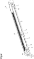
- the filament unit 2 includes a filament (an electron discharge part) 10, a main frame (a frame) 11, a grid electrode 12, a sub frame 13, a power supply line 14, a guide member 15, a terminal holding member 16, a filament fixing member 17, and a tension holding unit 20.
- the main frame 11 is a long member having a substantially U-shaped (C-shaped) cross section.
- the main frame 11 is disposed such that an opening having a substantially U-shaped cross section faces the front side (a side of the window 9).
- the filament fixing member 17 is provided at the other end of the main frame 11 in the inside (an inside space) of the main frame 11.
- the tension holding unit 20 is provided at one end of the main frame 11 in the inside (the inside space) of the main frame 11.
- the filament 10 is an electron discharge part that discharges electrons that become the electron beams EB when heated by energization.
- the filament 10 is a linear member and extends on a desired axis L extending from one side to the other side.
- the filament 10 is formed of a metal material having a high melting point, for example, a material containing tungsten as a main component.
- One end of the filament 10 is connected to the tension holding unit 20.
- the other end of the filament 10 is connected to the filament fixing member 17.
- the main frame 11 supports the tension holding unit 20 connected to the one end of the filament 10 and the filament fixing member 17 connected to the other end of the filament 10.
- the terminal holding member 16 is attached to the other end of the main frame 11.
- the terminal holding member 16 holds a filament terminal T1 for supplying a current for the filament 10 to discharge electrons, a high voltage terminal T2 for supplying a cathode potential to the filament unit 2, and a grid electrode terminal T3 for supplying an applied voltage to the grid electrode 12 in a state where the terminals T1, T2, and T3 are electrically insulated from each other.
- the filament terminal T1 is connected to the other end of the power supply line 14.
- the high voltage terminal T2 is electrically connected to the filament fixing member 17.
- the sub frame 13 is a long member having a substantially U-shaped cross section.
- the sub frame 13 is disposed parallel to the main frame 11.
- the power supply line 14 is connected to the tension holding unit 20 from a connection position with the filament terminal T1 through the inside (an inside space) of the sub frame 13.
- the sub frame 13 has a protective function for the power supply line 14.
- the main frame 11 and the sub frame 13 are connected to each other by a plurality of guide members 15. An outer surface of the guide member 15 is slidably in contact with an inner surface of the rail 6.
- the grid electrode 12 is disposed on the front side with respect to the filament 10 and is supported by the guide member 15 via an insulation member 18. A plurality of holes are formed in the grid electrode 12 (see FIG. 4 and the like). The grid electrode 12 is electrically connected to the grid electrode terminal T3 via a wiring (not shown).
- the tension holding unit 20 holds tension of the filament 10.
- the tension holding unit 20 can hold the tension of the filament 10 by pressing or pulling a movable body connected to the one end of the filament 10 by a spring.
- the tension holding unit 20 holds the tension of the filament 10 by pulling the movable body by the spring.
- the tension holding unit 20 is attached to the main frame 11 in a state where the tension holding unit 20 is electrically insulated from the main frame 11 via an insulation member or the like.
- One end of the power supply line 14 is connected to the tension holding unit 20.
- the tension holding unit 20 can supply the electric power supplied via the power supply line 14 to the filament 10 while holding the tension of the filament 10.
- the filament unit 2 is inserted into the inside (the inside space) of the rail 6 through the insertion holes provided in the cathode holding member 5 and the insulation support member 8 with the other end provided with the filament terminal T1 or the like as a head and is fixed thereto.
- tip ends of the filament terminal T1, the high voltage terminal T2, and the grid electrode terminal T3 are in contact with tip ends of three connection terminals provided in the high voltage introduction insulation member 7.
- the filament terminal T1 and the like are electrically connected to the connection terminals provided in the high voltage introduction insulation member 7.
- the filament 10 discharges electrons when a high negative voltage such as minus several tens of kV to minus several hundreds of kV is applied in a state where the filament 10 is heated by energization.
- a predetermined voltage is applied to the grid electrode 12.
- a voltage on a positive side of about 100 V to 150 V with respect to the negative voltage applied to the filament 10 may be applied to the grid electrode 12.
- the grid electrode 12 forms an electric field for drawing out electrons and curbing diffusion of the electrons. As a result, the electrons discharged from the filament 10 are emitted to the front side as the electron beams EB from the holes provided in the grid electrode 12.
- a side (the other side) on which the filament 10 is provided with respect to the tension holding unit 20 is referred to as a "left side”
- a side (one side) on which the tension holding unit 20 is provided with respect to the filament 10 is referred to as a "right side.” That is, a left-right direction is a direction along the axis L extending from the one side to the other side.
- the tension holding unit 20 includes a movable body (a movable part) 21, a housing (a support part, a housing part) 22, a spring (a tension holding part) 23, and a foil material (a power supply path part) 24.
- the movable body 21 is connected to the one end of the filament 10.
- the movable body 21 has a circular column 21a and a connection part 21b.
- the circular column 21a has a circular column shape extending in the left-right direction.
- the one end of the filament 10 is fixed to an end of the circular column 21a on the left side.
- various methods can be adopted.
- connection part 21b is connected to an end of the circular column 21a on the right side.
- the other end of the spring 23 and the other end of the foil material 24 are connected to the connection part 21b.
- the movable body 21 is formed of a conductive material.
- the movable body 21 is formed of, for example, a material such as stainless steel, copper, or a copper alloy.
- the movable body 21 is provided on the axis L.
- a state in which the movable body 21 is provided on the axis L is a disposition state in which the axis L is positioned inside an outer edge of the movable body 21 when viewed from the direction along the axis L.
- the same intention applies to a state in which other members are provided on the axis L.
- the movable body 21 may be disposed such that a position of a center of gravity of the movable body 21 is positioned on the axis L.
- the housing 22 is a box body having an accommodation space (an internal space) S inside.
- the spring 23, the foil material 24, and the end of the movable body 21 on the right side are accommodated in the accommodation space S of the housing 22.
- the housing 22 may be constituted by a box part 22a having an open surface such that the spring 23 and the like can be accommodated in the accommodation space S and a lid 22b covering an opening of the box part 22a.
- a guide hole (a movable part holding part) 22d is provided in a filament side wall 22c (a wall on the left side which constitutes the housing 22) which is a wall of the housing 22 on a side of the filament 10 (the other side).
- the guide hole 22d extends along the axis L.
- the guide hole 22d is a through hole having a circular column shape extending along the axis L.
- a diameter of the guide hole 22d is larger than a diameter of the circular column 21a of the movable body 21 by a desired value.
- the guide hole 22d guides the circular column 21a of the movable body 21 to be movable along the axis L. That is, the housing 22 holds the movable body 21 to be movable along the axis L by the guide hole 22d.
- a power supply line connection part 22f to which the one end of the power supply line 14 is connected is provided in a power supply side wall 22e (a wall on the right side constituting the housing 22) which is a wall on a side (the one side) opposite to a side of the filament 10 in the housing 22.
- the end of the power supply line 14 is electrically connected to the housing 22 by a bolt at the power supply line connection part 22f.
- the housing 22 is electrically connected to a power source device (a power supply device) that supplies power to the filament 10 via the power supply line 14 and the like.
- the housing 22 is formed of a conductive material.
- the housing 22 is formed of, for example, a material such as stainless steel, copper, or a copper alloy.
- the spring 23 is accommodated in the accommodation space S of the housing 22.
- the spring 23 is provided on the axis L.
- the other end of the spring 23 is connected to an end of the connection part 21b on the right side.
- a connection position between the spring 23 and the connection part 21b is positioned on the axis L.
- One end of the spring 23 is connected to the power supply side wall 22e of the housing 22.
- the housing 22 covers the spring 23 such that the spring 23 cannot be seen directly from the filament 10.
- a connection position (a connection portion) between the spring 23 and the movable body 21 is positioned in the accommodation space S.
- the spring 23 is a tension spring.
- the spring 23 applies a tensile force to the movable body 21 such that the movable body 21 moves along the axis L. That is, the spring 23 pulls the movable body 21 in one side direction along the axis L from the connection position to the movable body 21.
- the movable body 21 connects the one end of the filament 10 and the other end of the spring 23 to each other.
- the spring 23 pulls the filament 10 via the movable body 21 by applying a tensile force to the movable body 21 and holds the tension of the filament 10.
- the spring 23 is formed of, for example, a material such as stainless steel or Inconel.
- the spring 23 may be formed of a material which is different from the filament 10.
- a load of the spring 23 needs to be in a desired range during an operation (when the filament 10 is energized), and if the load deviates from that range, problems such as loosening, plastic deformation, and disconnection of the filament 10 may occur. Therefore, when the load of the spring 23 is Fa, an allowable tensile load of the filament 10 is Fx, and the sum of a weight and a frictional force of the movable body 21 is Fy, a relationship of Fx + Fy > Fa needs to be established.
- the heating of the filament 10 by energization causes a relationship of the allowable tensile load of the filament 10, that is, the allowable tensile load Fx1 at a room temperature > the allowable tensile load Fx2 at the time of heating. Therefore, the load of the spring 23 is preferably in the range of 0.01 N to 1000 N, more preferably 0.01 N to 100 N, and even more preferably 0.1 N to 10 N.
- the foil material 24 is accommodated in the accommodation space S of the housing 22.
- the foil material 24 serves as a power supply path for supplying the electric power supplied to the housing 22 via the power supply line 14 to the movable body 21.
- One end of the foil material 24 is connected to the power supply side wall 22e of the housing 22, and the other end of the foil material 24 is connected to the connection part 21b of the movable body 21.
- a connection portion between the foil material 24 and the movable body 21 is positioned in the accommodation space S.
- the foil material 24 is electrically connected to the filament 10 via the movable body 21.
- the foil material 24 is formed of a material having a better electrical conductivity than the spring 23.
- an electric resistance value of the spring 23 is larger than an electric resistance value of the foil material 24.
- the foil material 24 is formed of, for example, copper or the like as a material having a good electrical conductivity and a good flexibility.
- the electric resistance is about 6 ⁇ .
- copper is used as the material of the foil material 24, and a length thereof is, for example, 50 mm.
- An electrical resistivity of copper is 1.7 ⁇ 10 -8 ⁇ m. Therefore, if a cross-sectional area of the foil material 24 is 1.4 ⁇ 10 -2 mm 2 or more, the electric resistance value of the foil material 24 can be sufficiently lowered to 1/100 or less of the electric resistance value of the spring 23 formed of stainless steel.
- the foil material 24 is a thin film shaped member formed of a metal (a metal thin film part). A thickness of the foil material 24 is thinner than a width of the foil material 24, and the width of the foil material 24 is smaller than a length of the foil material 24.
- the foil material 24 extends from the power supply side wall 22e toward the movable body 21 and is fixed to the connection part 21b in a state where a tip end is folded back in a U shape.
- the foil material 24 has a folded-back part 24a which is folded back in a U shape and includes regions which are overlapped each other (doubled) in a positional relationship along the axis L at an end on the left side thereof, and the regions are separated from each other in a direction perpendicular to the axis L. Therefore, the length of the foil material 24 is longer than that of the spring 23 and longer than a length (a length of a straight line) from a connection position A between the foil material 24 and the power supply side wall 22e to a connection position B between the foil material 24 and the movable body 21.
- the foil material 24 can maintain a state in which the power supply side wall 22e and the movable body 21 are connected to each other while allowing the movable body 21 to move.
- the housing 22 may further include a partitioning part 22g in which one end is fixed to the power supply side wall 22e and the other end extends toward the movable body 21.
- the partitioning part 22g extends from the end of the spring 23 on the left side to the end of the spring 23 on the left side to place the foil material 24 in a state where the partitioning part 22g is separated from the spring 23 and partitions the spring 23 and the foil material 24 from each other. As a result, the foil material 24 is prevented from coming into contact with the spring 23.
- a length (a free length) of the spring 23 is such that a tensile force can be applied to the movable body 21 even in a case where a length of the filament 10 becomes longer due to thermal expansion.
- the material forming the filament 10 is tungsten
- the filament 10 becomes longer by about 5 mm due to thermal expansion with a coefficient of linear expansion of tungsten of 5.2 ⁇ 10 -6 [1/K] (2000 °C).
- the movable body 21 needs to be able to move by at least about 5 mm.
- the tension holding unit 20 can maintain the tension of the filament 10 with the tensile force of the spring 23 even in a case where the length of the filament 10 changes due to thermal expansion. In this way, a state where the filament 10 is stretched in a straight linear shape by the tension holding unit 20 is maintained.
- the power supply side wall 22e to which the power supply line 14 is connected and the movable body 21 to which the filament 10 is connected are connected to each other by the spring 23 and the foil material 24.
- the foil material 24 is formed of a material having a better electrical conductivity than the spring 23.
- the electric power is supplied from the power supply side wall 22e to the movable body 21 mainly through the foil material 24 rather than the spring 23.
- heat generation of the spring 23 due to energization is curbed, and thus fluctuations in the tensile force, deterioration, or the like of the spring 23 due to the influence of heat is curbed.
- the tension holding unit 20 can hold the tension of the filament 10 by the spring 23 while supplying the electric power to the filament 10 through the foil material 24 via the movable body 21. More specifically, since the electric power supply to the filament 10 is performed via the movable body 21, the movable body 21 is in charge of rubbing or the like due to the mechanical sliding operation caused by the expansion and contraction of the spring 23, and thus it is possible to curb the influence on the holding of the tension of the filament 10 by the spring 23 and the electric power supply to the filament 10 by the foil material 24 while curbing the mechanical damage to the filament 10.
- the electron beam emission device 1 (the filament unit 2), the filament 10, the movable body 21, and the spring 23 are provided on the same axis L. Therefore, the electron beam emission device 1 can easily apply the tensile force of the spring 23 to the filament 10 via the movable body 21 in the direction of the axis L. As a result, even in a case where the tensile force of the spring 23 is applied, axial deviation (deviation from the axis L) of the filament 10 is curbed. In this way, the electron beam emission device 1 can appropriately apply the tensile force of the spring 23 to the filament 10 to curb the axial deviation of the filament 10. As a result, it is possible to obtain more uniform electron discharge distribution.
- the spring 23 applies a tensile force to the movable body 21 such that the movable body 21 moves along the axis L.
- the electron beam emission device 1 can further curb the axial deviation of the filament 10 in a case where the tensile force of the spring 23 is applied.
- the electron beam emission device 1 can further curb the axial deviation of the filament 10.
- the electron beam emission device 1 can curb the conduction of heat from the filament 10 to the spring 23 and can curb the heating of the spring 23.
- the spring 23 is accommodated in the accommodation space S of the housing 22.
- the electron beam emission device 1 can curb the influence of the radiant heat from the filament 10 on the spring 23.
- the electron beam emission device 1 can curb fluctuations in the tensile force of the spring 23 due to the influence of heat and deterioration due to heat and can stably hold the tension of the filament 10.
- the housing 22 covers the spring 23 such that the spring 23 cannot be seen directly from the filament 10.
- the electron beam emission device 1 can prevent the electrons discharged from the filament 10 from directly hitting the spring 23 and can curb heating deterioration and damage caused by the collision of the electrons.
- the housing 22 is provided with the guide hole 22d extending along the axis L and holding the movable body 21 to be movable along the axis L. In this case, the housing 22 can stably hold the movable body 21 to be movable by the guide hole 22d.
- the guide hole 22d is a through hole having a circular column shape extending along the axis L.
- the movable body 21 can rotate in the guide hole 22d.
- the tension holding unit 20 for example, even if the spring 23 is twisted at the time of expansion and contraction of the spring 23 and a force in a rotational direction is applied to the movable body 21, it is possible to hold the tension of the filament 10 while curbing the concentration of a force of the twisting on a part of the movable body 21 by the rotation of the movable body 21 in the guide hole 22d.
- the electron beam emission device 1 can curb the influence of the twisting even in a case where the spring 23 is twisted.
- the filament 10 has a straight linear shape due to the tension being held by the tension holding unit 20.
- the electron beam emission device 1 can uniformly emit electrons at each position in the direction of the axis L.
- the filament unit 2 includes the main frame 11 that holds the tension holding unit 20 to which the one end of the filament 10 is connected and the filament fixing member 17 to which the other end of the filament 10 is connected.
- the filament unit 2 can be easily handled by making the filament unit 2 into one body using the main frame 11. Further, since the filament unit 2 can be attached to and detached from the rail 6 of the electron beam emission device 1, and the filament 10 and the tension holding unit 20 are attached to and detached from the rail 6 of the electron beam emission device 1 together with the filament unit 2.
- a tension holding unit 20A in a first modification example includes a movable body 21A, a housing 22A, a spring 23, and an annular elastic body (a power supply path part) 25.
- the movable body 21A has a circular column shape extending in the left-right direction.
- the one end of the filament 10 is fixed to an end of the movable body 21A on the left side.
- the other end of the spring 23 is connected to an end of the movable body 21A on the right side.
- the movable body 21A is provided on the axis L. Further, the movable body 21A is disposed such that a position of a center of gravity of the movable body 21A is positioned on the axis L.
- the movable body 21A is formed of a conductive material.
- the movable body 21A is formed of, for example, a copper alloy, stainless steel, or the like as a material having a good electrical conductivity.
- the housing 22A is a box body having an accommodation space S inside.
- the spring 23 is accommodated in the accommodation space S of the housing 22A.
- the housing 22A may be constituted by a box part 22a having an open surface such that the spring 23 can be accommodated in the accommodation space S.
- a guide hole 22d is provided in a filament side wall 22c of the housing 22A.
- a diameter of the guide hole 22d is larger than a diameter of the movable body 21A by a desired value.
- a length of the guide hole 22d in the direction of the axis L is longer than a length of the movable body 21A.
- the guide hole 22d guides the movable body 21A to be movable along the axis L.
- the housing 22A holds the movable body 21A to be movable along the axis L by the guide hole 22d.
- the housing 22A is formed of a conductive material.
- the housing 22A is formed of, for example, a copper alloy, stainless steel, or the like as a material having a good electrical conductivity.
- the spring 23 is provided on the axis L.
- the other end of the spring 23 is connected to an end of the movable body 21A on the right side.
- a connection position between the spring 23 and the movable body 21A is positioned on the axis L.
- One end of the spring 23 is connected to a power supply side wall 22e of the housing 22A.
- the housing 22A covers the spring 23 such that the spring 23 cannot be seen directly from the filament 10.
- the spring 23 applies a tensile force to the movable body 21A such that the movable body 21A moves along the axis L. That is, the spring 23 pulls the movable body 21A in one side direction along the axis L from the connection position to the movable body 21A. As a result, the spring 23 pulls the filament 10 via the movable body 21A by applying a tensile force to the movable body 21A and holds the tension of the filament 10.
- the annular elastic body 25 is accommodated in the guide hole 22d of the housing 22A.
- the annular elastic body 25 serves as a power supply path for supplying the electric power supplied to the housing 22A via the power supply line 14 to the movable body 21A.
- the annular elastic body 25 is formed of an elastic member having an annular shape and conductivity.
- the annular elastic body 25 is fitted into a recess 21c extending over the entire region in a circumferential direction in an outer peripheral surface of the movable body 21A in a cross section in the direction perpendicular to the axis L.
- a portion of an outer peripheral edge (one end) of the annular elastic body 25 in a radial direction is in contact with an inner peripheral surface of the guide hole 22d of the housing 22A and is electrically connected thereto.
- a portion of an inner peripheral edge (the other end) of the annular elastic body 25 in the radial direction is in contact with an outer peripheral surface (an inner wall surface of the recess 21c) of the movable body 21A and is electrically connected thereto.
- a diameter of an outer periphery of the annular elastic body 25 is larger than a diameter of an outer periphery of the movable body 21A, and a diameter of an inner periphery of the annular elastic body 25 is smaller than at least a diameter of an outer periphery of the movable body 21A.
- the annular elastic body 25 is electrically connected to the housing 22A and is also electrically connected to the filament 10 via the movable body 21A.
- the annular elastic body 25 is formed of a material having a better electrical conductivity than the spring 23. That is, an electric resistance value of the spring 23 is larger than an electric resistance value of the annular elastic body 25.
- the annular elastic body 25 is formed of, for example, a copper alloy or the like as a material having a good electrical conductivity.
- the tension holding unit 20A can maintain the tension of the filament 10 with the tensile force of the spring 23 as in the tension holding unit 20 in the embodiment.
- the housing 22A and the movable body 21A are connected to each other by the spring 23 and the annular elastic body 25.
- the annular elastic body 25 is formed of a material having a better electrical conductivity than the spring 23.
- the tension holding unit 20A can hold the tension of the filament 10 by the spring 23 while supplying the electric power to the filament 10 through the annular elastic body 25 via the movable body 21A.
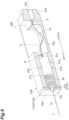
- a tension holding unit 20B in a second modification example includes a movable body 21B, a housing 22B, a spring (a tension holding part) 26, and a foil material (a power supply path part) 27.
- the movable body 21B is connected to the one end of the filament 10.
- the movable body 21B has a circular column 21a and a small-diameter circular column 21d.
- the small-diameter circular column 21d includes a main body 21d1 having a diameter smaller than that of the circular column 21a and a tip end 21d2 having a diameter smaller than that of the main body 21d1.
- the main body 21d1 is connected to an end of the circular column 21a on the left side, and the tip end 21d2 is connected to an end of the main body 21d1 on the left side.
- the one end of the filament 10 is fixed to an end of the tip end 21d2 of the small-diameter circular column 21d on the left side.
- the movable body 21B is provided on the axis L. Further, the movable body 21B is disposed such that a position of a center of gravity of the movable body 21B is positioned on the axis L.
- the movable body 21B is formed of a conductive material.
- the movable body 21B is formed of, for example, a material such as stainless steel, copper, or a copper alloy.
- the housing 22B further includes a housing side spring receiving part (a housing side tension receiving part) 22h with respect to the housing 22A (see FIG. 8 ) in the first modification example.
- the housing side spring receiving part 22h is provided on a surface of the filament side wall 22c on a side of the filament 10 (the other side).
- the housing side spring receiving part 22h is provided with a small-diameter hole 22j through which the tip end 21d2 of the small-diameter circular column 21d of the movable body 21B can be inserted.
- a diameter of the small-diameter hole 22j is smaller than a diameter of a guide hole 22d and larger than a diameter of the tip end 21d2.
- the housing 22B is formed of a conductive material.
- the housing 22B is formed of, for example, a material such as stainless steel, copper, or a copper alloy.
- the spring 26 is accommodated in the guide hole 22d of the housing 22B.
- the spring 26 is provided on the axis L.
- the main body 21d1 of the small-diameter circular column 21d of the movable body 21B passes through the inside of the spring 26. That is, an outer diameter of the spring 26 is smaller than an inner diameter of the guide hole 22d, and an inner diameter of the spring 26 is larger than an outer diameter of the main body 21d1 of the small-diameter circular column 21d.
- One end of the spring 26 is in contact with an end face of the circular column 21a of the movable body 21B on the left side.
- the other end of the spring 26 is in contact with a surface of the housing side spring receiving part 22h on the right side.
- the end surface of the circular column 21a of the movable body 21B on the left side becomes a movable body side spring receiving part (a movable body side tension receiving part) 21e with which the spring 26 is in contact.
- the housing side spring receiving part 22h is positioned on a side of the filament 10 from the movable body side spring receiving part 21e.
- the spring 26 is disposed between the movable body side spring receiving part 21e and the housing side spring receiving part 22h.
- the housing side spring receiving part 22h covers the spring 26 such that the spring 26 cannot be seen directly from the filament 10 (partitions the filament 10 the spring 26 from each other).
- the spring 26 is a compression spring.
- the spring 26 applies a pressing force to the movable body 21B such that the movable body 21B moves along the axis L. That is, the spring 26 presses the movable body 21B in one side direction along the axis L from a contact position with the movable body 21B.
- the movable body 21B is connected to the one end of the filament 10.
- the spring 26 pulls the filament 10 in a right direction via the movable body 21B by applying a pressing force to the movable body 21B and holds the tension of the filament 10.
- the spring 26 is formed of, for example, a material such as stainless steel or Inconel.
- the spring 26 may be formed of a material which is different from the filament 10.
- the foil material 27 is accommodated in the accommodation space S of the housing 22B.
- the foil material 27 serves as a power supply path for supplying the electric power supplied to the housing 22B via the power supply line 14 to the movable body 21B.
- One end of the foil material 27 is connected to the power supply side wall 22e of the housing 22B, and the other end of the foil material 27 is connected to the circular column 21a of the movable body 21B.
- the foil material 27 is electrically connected to the filament 10 via the movable body 21B.
- the foil material 27 is formed of a material having a better electrical conductivity than the spring 26. That is, an electric resistance value of the spring 26 is larger than an electric resistance value of the foil material 27.
- the foil material 27 is formed of, for example, copper or the like as a material having a good electrical conductivity and a good flexibility.
- the foil material 27 is a thin film shaped member formed of a metal (a metal thin film part). A thickness of the foil material 27 is thinner than a width of the foil material 27, and the width of the foil material 27 is smaller than a length of the foil material 27. The length of the foil material 27 is longer than a length (a length of a straight line along the axis L) from a connection position A between the foil material 27 and the power supply side wall 22e to a connection position B between the foil material 27 and the movable body 21B.
- the foil material 24 can maintain a state in which the power supply side wall 22e and the movable body 21B are connected to each other while allowing the movable body 21B to move.
- the tension holding unit 20B can maintain the tension of the filament 10 with the pressing force of the spring 26.
- a length (a free length) of the spring 26 is such that a pressing force can be applied to the movable body 21B even in a case where a length of the filament 10 becomes longer due to thermal expansion.
- the tension holding unit 20B can maintain the tension of the filament 10 with the pressing force of the spring 26 even in a case where the length of the filament 10 changes due to thermal expansion. In this way, a state where the filament 10 is stretched in a straight linear shape by the tension holding unit 20B is maintained.
- the tension holding unit 20B the housing 22B and the movable body 21B are connected to each other by the spring 26 and the foil material 27.
- the foil material 27 is formed of a material having a better electrical conductivity than the spring 26.
- the electric power is supplied from the power supply side wall 22e to the movable body 21B mainly through the foil material 27 rather than the spring 26.
- heat generation of the spring 26 due to energization is curbed, and thus fluctuations in the pressing force or the like of the spring 26 due to the influence of heat is curbed.
- the tension holding unit 20B can hold the tension of the filament 10 by the spring 26 while supplying the electric power to the filament 10 through the foil material 27 via the movable body 21B.
- the electron beam emission device 1 (the filament unit 2) provided with the tension holding unit 20B, the filament 10, the movable body 21B, and the spring 26 are provided on the same axis L. Therefore, the electron beam emission device 1 can easily apply the pressing force of the spring 26 to the filament 10 via the movable body 21B in the direction of the axis L. As a result, even in a case where the pressing force of the spring 26 is applied, axial deviation (deviation from the axis L) of the filament 10 is curbed. In this way, the electron beam emission device 1 provided with the tension holding unit 20B can appropriately apply the pressing force of the spring 26 to the filament 10 to curb the axial deviation of the filament 10. As a result, it is possible to obtain more uniform electron discharge distribution.
- the spring 26 applies a pressing force to the movable body 21B such that the movable body 21B moves along the axis L.
- the electron beam emission device 1 provided with the tension holding unit 20B can further curb the axial deviation of the filament 10 in a case where the pressing force of the spring 26 is applied.
- the movable body 21B is disposed such that a position of a center of gravity of the movable body 21B is positioned on the axis L. In this case, even in a case where the pressing force of the spring 26 is applied, the movable body 21B swinging due to action of a moment is curbed. As a result, the electron beam emission device 1 provided with the tension holding unit 20B can further curb the axial deviation of the filament 10.
- the filament 10 and the spring 26 are formed of different members.
- the electron beam emission device 1 provided with the tension holding unit 20B can curb the conduction of heat from the filament 10 to the spring 26 and can curb the heating of the spring 26.
- the spring 26 is accommodated in the guide hole 22d of the housing 22B.
- the electron beam emission device 1 provided with the tension holding unit 20B can curb the influence of the radiant heat from the filament 10 on the spring 26.
- the electron beam emission device 1 provided with the tension holding unit 20B can curb fluctuations in the pressing force of the spring 26 due to the influence of heat and deterioration due to heat and can stably hold the tension of the filament 10.
- the small-diameter hole 22j provided in the housing side spring receiving part 22h has a smaller diameter than the guide hole 22d and has a diameter sufficient for the small-diameter circular column 21d to pass therethrough. Further, the housing side spring receiving part 22h covers the spring 26 such that the spring 26 cannot be seen directly from the filament 10. In this case, the electron beam emission device 1 provided with the tension holding unit 20B can prevent the electrons discharged from the filament 10 from directly hitting the spring 26 and can curb heating deterioration and damage caused by the collision of the electrons.
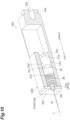
- a tension holding unit 20C in a third modification example is configured to include the annular elastic body 25 of the tension holding unit 20A (see FIG. 8 ) in the first modification example instead of the foil material 27 in the configuration of the tension holding unit 20B (see FIG. 9 ) in the second modification example.
- the tension holding unit 20C includes a movable body 21C, a housing 22B, an annular elastic body (a power supply path part) 25, and a spring 26.
- a recess 21c is provided in an outer peripheral surface of a circular column 21a of the movable body 21C.
- the annular elastic body 25 is fitted into the recess 21c of the circular column 21a.
- the tension holding unit 20C can maintain the tension of the filament 10 with the pressing force of the spring 26 as in the tension holding unit 20B in the second modification example. Further, in the tension holding unit 20C, the housing 22B and the movable body 21C are connected to each other by the annular elastic body 25 and spring 26.
- the annular elastic body 25 is formed of a material having a better electrical conductivity than the spring 26.
- the electric power is supplied from the housing 22B to the movable body 21C mainly through the annular elastic body 25 rather than the spring 26.
- heat generation of the spring 26 due to energization is curbed, and thus fluctuations in the pressing force or the like of the spring 26 due to the influence of heat is curbed.
- the tension holding unit 20C can hold the tension of the filament 10 by the spring 26 while supplying the electric power to the filament 10 through the annular elastic body 25 via the movable body 21C.
- a tension holding unit 20D in a fourth modification example further includes an insulation ring (an insulation member) 28 and an insulation ring (and insulation member) 29 with respect to the configuration of the tension holding unit 20B (see FIG. 9 ) in the second modification example. That is, the tension holding unit 20D includes a movable body 21B, a housing 22B, a spring 26, a foil material 27, an insulation ring 28, and an insulation ring 29.
- the insulation ring 28 is disposed between the spring 26 and a housing side spring receiving part 22h.
- the insulation ring 28 electrically insulates the housing 22B and the spring 26 from each other.
- the insulation ring 28 is formed of a material having a less conductivity than the spring 26.
- An outer edge of the insulation ring 28 projects toward the spring 26 in a direction along the axis L to surround an outer peripheral portion of the spring 26. As a result, the insulation ring 28 can prevent the outer peripheral portion of the spring 26 from coming into contact with the inner peripheral surface of the guide hole 22d.
- the spring 26 is also positioned in the direction perpendicular to the axis L by an inner peripheral portion of the insulation ring 28, and thus the contact between the spring 26 and the small-diameter circular column 21d of the movable body 21B is also curbed.
- the insulation ring 29 is disposed between the movable body side spring receiving part 21e of the circular column 21a of the movable body 21B and the spring 26.
- the insulation ring 29 electrically insulates the movable body 21B and the spring 26 from each other.
- the insulation ring 29 is formed of a material having a less conductivity than the spring 26.
- An outer edge of the insulation ring 29 projects toward the spring 26 in a direction along the axis L to surround an outer peripheral portion of the spring 26. As a result, the insulation ring 29 can prevent the outer peripheral portion of the spring 26 from coming into contact with the inner peripheral surface of the guide hole 22d.
- the spring 26 is also positioned in the direction perpendicular to the axis L by an inner peripheral portion of the insulation ring 29, and thus the contact between the spring 26 and the small-diameter circular column 21d of the movable body 21B is also curbed.
- the tension holding unit 20D may be configured to include only any one of the insulation ring 28 and the insulation ring 29.
- the tension holding unit 20D in the fourth modification example can further curb the flow of electricity to the spring 26 by providing the insulation rings 28 and 29.
- the tension holding unit 20D can further curb heat generation of the spring 26 due to energization.
- a tension holding unit 20E in a fifth modification example further includes an insulation ring (an insulation member) 28 and an insulation ring (and insulation member) 29 with respect to the configuration of the tension holding unit 20C (see FIG. 10 ) in the third modification example. That is, the tension holding unit 20E includes a movable body 21C, a housing 22B, an annular elastic body 25, a spring 26, an insulation ring 28, and an insulation ring 29.
- the insulation rings 28 and 29 have the same configuration as the insulation rings 28 and 29 in the fourth modification example.
- the tension holding unit 20E in the fifth modification example can further curb the flow of electricity to the spring 26 by providing the insulation rings 28 and 29.
- the tension holding unit 20E can further curb heat generation of the spring 26 due to energization.
- a portion to which the spring 23 is connected may be made of an insulation material (for example, ceramic or the like).
- the portion of the connection part 21b to which the spring 23 is connected may be subjected to insulation coating.
- the spring 23 of the tension holding unit 20 may be subjected to insulation coating.
- a portion to which the spring 23 is connected may be made of an insulation material (for example, ceramic or the like).
- the portion of the movable body 21A to which the spring 23 is connected may be subjected to insulation coating.
- the spring 23 of the tension holding unit 20A may be subjected to insulation coating. Even in these cases, the tension holding units 20 and 20A can further curb the flow of electricity to the spring 23 and can further curb heat generation of the spring 23 due to energization.
- the housing 22 of the tension holding unit 20 in the embodiment is divided into two.
- the tension holding unit 20F includes a movable body 21, a housing 22F, a spring 23, and a foil material 24.
- the housing 22F includes a first housing 22k and a second housing 22m.
- the first housing 22k is provided with the guide hole 22d through which the circular column 21a of the movable body 21 passes.
- the second housing 22m has the accommodation space S for accommodating the spring 23 and a portion of the foil material 24 on a side of the power supply side wall 22e.
- the first housing 22k and the second housing 22m are attached to the main frame 11 of the filament unit 2 via an insulation material. That is, the first housing 22k and the second housing 22m are electrically insulated from each other.
- the tension holding unit 20F can supply the electric power to the movable body 21 from the power supply side wall 22e via the foil material 24 without directly supplying the electric power to the movable body 21 from the inner peripheral surface of the guide hole 22d provided in the first housing 22k. In this way, the tension holding unit 20F is not configured to supply the electric power via the members sliding on each other, and thus it is possible to supply the electric power to the movable body 21 more reliably.
- the housing 22A of the tension holding unit 20A in the first modification example is divided into two.
- the tension holding unit 20G includes a movable body 21A, a housing 22G, a spring 23, and an annular elastic body 25.
- the housing 22G includes a first housing 22n and a second housing 22p.
- the first housing 22n is provided with the guide hole 22d through which the movable body 21A passes.
- the one end of the spring 23 is connected to an end of the movable body 21A on the right side.
- the other end of the spring 23 is connected to the second housing 22p.
- the first housing 22n and the second housing 22p are attached to the main frame 11 of the filament unit 2 via an insulation material. That is, the first housing 22n and the second housing 22p are electrically insulated from each other.
- the end of the power supply line 14 is connected to the first housing 22n.
- the tension holding unit 20G the electric power is supplied from the first housing 22n to the filament 10 via the annular elastic body 25 and the movable body 21A.
- heat generation of the spring 23 due to energization is curbed, and thus fluctuations in the tensile force or the like of the spring 23 due to the influence of heat is curbed.
- the tension holding unit 20G can hold the tension of the filament 10 by the spring 23 while supplying the electric power to the filament 10 through the annular elastic body 25 via the movable body 21A.
- a method of fixing the filament 10 to the tip end of the movable body 21 of the tension holding unit 20 in the embodiment is also applicable to the various modification examples of the tension holding unit described above.
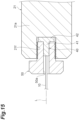
- a bolt hole 21f extending along the axis L is provided in the tip end surface (the other end surface) of the circular column 21a of the movable body 21.
- a filament fixing member 40 is attached to the tip end (the one end side) of the filament 10.
- the filament fixing member 40 includes a tubular part 41 and a flange 42. The tip end of the filament 10 is inserted into the tubular part 41 and fixed thereto.
- the tubular part 41 may be attached to the filament 10 by the tip end of the filament 10 being placed on an inner peripheral surface thereof by caulking.
- the flange 42 protrudes outward from the outer peripheral surface of the end of the tubular part 41 on a side of the movable body 21.
- the filament fixing member 40 is fixed to the tip end of the movable body 21 by a perforated bolt 50.
- the perforated bolt 50 is provided with a through hole 50a extending in an axial direction of the perforated bolt 50.
- the tubular part 41 of the filament fixing member 40 and a part of the filament 10 are inserted into the through hole 50a such that the flange 42 comes into contact with the tip end of the perforated bolt 50.
- the perforated bolt 50 is attached to the bolt hole 21f of the circular column 21a in a state where the tubular part 41 or the like is inserted into the through hole 50a.
- the filament fixing member 40 attached to the tip end of the filament 10 is fixed to the tip end of the circular column 21a when the flange 42 is sandwiched between the tip end of the perforated bolt 50 and a bottom portion of the bolt hole 21f of the circular column 21a.
- the filament 10 can be easily attached to and detached from the movable body 21 using the perforated bolt 50.
- the movable body 21 can easily pull the filament 10 in the direction of the axis L while curbing the axial deviation.
- the present disclosure is not limited to the above embodiment and various modification examples.
- the configurations which will be described below are applicable to all the embodiment and various modification examples as much as possible.
- the spring 23 may not be a configuration in which the spring 23 pulls the movable body 21 in a direction along the axis L as long as a configuration in which, for example, the moving direction of the movable body 21 is guided the guide hole 22d is provided.
- the moving direction of the movable body 21 only has to be guided in a direction of the axis L by the guide hole 22d.
- the movable body 21 is not limited to that the position of a center of gravity of the movable body 21 is positioned on the axis L.
- the spring 23 is not limited to being accommodated in the accommodation space S of the housing 22.
- the spring 23 may be configured not to be accommodated in the accommodation space S.
- the spring 23 is not limited to the configuration in which the spring 23 is disposed not to be directly seen from the filament 10.
- the movable body 21 may not be guided by the guide hole 22d of the housing 22.
- the shape of the movable body 21 and the guide hole 22d is not limited to the circular column shape extending along the axis L.
- the movable body 21 and the guide hole 22d may have a shape other than the circular column shape, for example, a polygonal shape.
- the filament 10 is not limited to the straight linear member in all parts.
- the filament 10 may have a coiled part having a coiled shape.
- the filament 10 can hold the tension of the filament 10 even by its own coiled part. In this way, the electron beam emission device can have a function of holding tension with respect to the filament 10.
- the filament unit 2 may be used as an electron beam generation source provided in an X-ray emission device that emits X-rays.
- the X-ray emission device further includes a main body that accommodates the filament unit 2, an X-ray target (for example, tungsten, molybdenum, or the like) as an X-ray generation part that generates X-rays when electrons are incident from the filament unit 2, and an X-ray extraction part for extracting X-rays to the outside of the main body.
- a window for X-ray emission constituted by a window material having a high X-ray permeability (for example, beryllium, diamond, or the like) and the X-ray target provided on a surface of the window material on a side of the vacuum space R.
- a window material having a high X-ray permeability for example, beryllium, diamond, or the like
- the electron beams EB emitted from the filament unit 2 can be incident on the X-ray target, and the X-rays can be emitted from the X-ray target.
Landscapes
- Electron Sources, Ion Sources (AREA)
- X-Ray Techniques (AREA)
Abstract
Description
- The present disclosure relates to an electron beam generation source, an electron beam emission device, and an X-ray emission device.
- A fluorescent display tube that discharges electrons from an electron discharge part toward a phosphor to emit light from the phosphor is described in Patent Literature 1. In an electron beam generation source of this fluorescent display tube, tension of the electron discharge part is held by applying a pressing force of a tension holding part (a spring) to the electron discharge part having a linear shape.
- [Patent Literature 1]
Japanese Unexamined Patent Publication No. H8-264138 - In the above fluorescent display tube, the electron discharge part having a linear shape and the tension holding part are disposed parallel to each other, and ends of both are connected by a connecting part, and thus the pressing force of the tension holding part is applied to the electron discharge part. In such a configuration, it is difficult to apply the pressing force of the tension holding part to the electron discharge part along an axis of the electron discharge part, and axial deviation of the electron discharge part may occur due to action of a moment.
- Therefore, an object of the present disclosure is to provide an electron beam generation source, an electron beam emission device, and an X-ray emission device in which a pressing force or a tensile force of a tension holding part can be appropriately applied to an electron discharge part to curb axial deviation of the electron discharge part.
- According to an aspect of the present disclosure, there is provided an electron beam generation source including: an electron discharge part extending on a desired axis and configured to discharge electrons; a movable part connected to one end of the electron discharge part; a support part configured to support the movable part to be movable along the axis; and a tension holding part configured to hold tension of the electron discharge part by applying a pressing force or a tensile force to the movable part, wherein the movable part and the tension holding part are disposed on the axis.
- In this electron beam generation source, the electron discharge part, the movable part, and the tension holding part are provided on the same axis. Therefore, the electron beam generation source can easily apply the pressing force or the tensile force of the tension holding part to the electron discharge part in an axial direction via the movable part. As a result, even in a case where the pressing force or the tensile force of the tension holding part is applied, axial deviation of the electron discharge part is curbed. In this way, the electron beam generation source can appropriately apply the pressing force or the tensile force of the tension holding part to the electron discharge part to curb the axial deviation of the electron discharge part.
- The tension holding part may apply the pressing force or the tensile force to the movable part such that the movable part moves along the axis. In this case, the electron beam generation source can further curb the axial deviation of the electron discharge part in a case where the pressing force or the tensile force of the tension holding part is applied.
- The movable part may be disposed such that a position of a center of gravity of the movable part is positioned on the axis. In this case, even in a case where the pressing force or the tensile force of the tension holding part is applied, the movable part swinging due to action of a moment is curbed. As a result, the electron beam generation source can further curb the axial deviation of the electron discharge part.
- The electron discharge part and the tension holding part may be made of different members. In this case, the electron beam generation source can curb the conduction of heat from the electron discharge part to the tension holding part and can curb the heating of the tension holding part.
- The support part may include a housing part having an internal space for accommodating the tension holding part inside. In this case, the electron beam generation source can curb the influence of the radiant heat from the electron discharge part on the tension holding part by the housing part provided in the support part. As a result, the electron beam generation source can curb fluctuations in the pressing force or the tensile force of the tension holding part due to the influence of heat and deterioration due to heat and can stably hold the tension of the electron discharge part.
- The housing part may cover the tension holding part such that the tension holding part cannot be directly seen from the electron discharge part. In this case, the electron beam generation source can prevent the electrons discharged from the electron discharge part from directly hitting the tension holding part and can curb heating deterioration and damage caused by the collision of the electrons.
- The housing part may include a movable part holding part that extends along the axis and holds the movable part to be movable along the axis. In this case, the housing part can stably hold the movable part to be movable by the movable part holding part.
- The movable part holding part may be a through hole extending along the axis and having a circular column shape. In this case, the movable part can rotate in the through hole. For example, when the tension holding part expands and contracts, the tension holding part is twisted, and thus a force in a rotational direction may be applied to the movable part. Even in this case, the rotation of the movable part in the through hole curbs the concentration of a force of the twisting on a part of the movable part, and the tension of the electron discharge part is maintained. As a result, the electron beam generation source can curb the influence of the twisting even in a case where the tension holding part is twisted.
- The electron discharge part may have a straight linear shape. In this case, the electron beam generation source can uniformly emit electrons at each position in an axial direction.
- The electron discharge part may have a coiled part having a coiled shape. In this case, the electron beam generation source can have a function of holding tension with respect to the electron discharge part.
- The electron beam generation source may further include a frame configured to support the other end of the electron discharge part and the tension holding part. In this case, the electron beam generation source can be easily handled by making the electron beam generation source into one body using the frame.
- There may be provided an electron beam emission device including: such an electron beam generation source; a main body configured to accommodate the electron beam generation source; and an electron extraction part configured to extract electrons from the electron beam generation source to the outside of the main body. Further, there may be provided an X-ray emission device including: such an electron beam generation source; a main body configured to accommodate the electron beam generation source; an X-ray generation part configured to generate X-rays when electrons are incident from the electron beam generation source; and an X-ray extraction part configured to extract the X-rays to the outside of the main body. In this case, it is possible to obtain an electron beam emission device and an X-ray emission device capable of curbing the axial deviation of the electron discharge part.
- According to the present disclosure, a pressing force or a tensile force of a tension holding part can be appropriately applied to an electron discharge part to curb axial deviation of the electron discharge part.
-
-
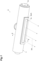
FIG. 1 is a perspective view of an electron beam emission device according to an embodiment. -
FIG. 2 is a partial cross-sectional view showing an internal structure of the electron beam emission device ofFIG. 1 . -
FIG. 3 is a cross-sectional view along line III-III ofFIG. 1 . -
FIG. 4 is a perspective view of a filament unit. -
FIG. 5 is a cross-sectional view of the filament unit. -
FIG. 6 is a cross-sectional perspective view of a tension holding unit. -
FIG. 7 is a cross-sectional view of the tension holding unit. -
FIG. 8 is a cross-sectional perspective view of a tension holding unit of a first modification example. -
FIG. 9 is a cross-sectional perspective view of a tension holding unit of a second modification example. -
FIG. 10 is a cross-sectional perspective view of a tension holding unit of a third modification example. -
FIG. 11 is a cross-sectional perspective view of a tension holding unit of a fourth modification example. -
FIG. 12 is a cross-sectional perspective view of a tension holding unit of a fifth modification example. -
FIG. 13 is a cross-sectional perspective view of a tension holding unit of a sixth modification example. -
FIG. 14 is a cross-sectional perspective view of a tension holding unit of a seventh modification example. -
FIG. 15 is a cross-sectional view showing an example of an attachment structure of a filament to a movable body. - Hereinafter, an embodiment of the present disclosure will be described with reference to the drawings. In the drawings, the same or corresponding elements will be denoted by the same reference signs and redundant description will be omitted.
- An electron beam emission device 1 shown in
FIG. 1 is used for, for example, ink curing, sterilizing, or surface reforming on an irradiation target by irradiating the irradiation target with electron beams EB. Hereinafter, an electron beam emitting side (a side of a window 9) which is a side from which the electron beams EB are emitted by the electron beam emission device 1 will be described as a "front side." - As shown in
FIGS. 1 to 3 , the electron beam emission device 1 includes a filament unit (an electron beam generation source) 2, a vacuum container (a main body) 3, acathode holding member 4, acathode holding member 5, arail 6, a high voltageintroduction insulation member 7, aninsulation support member 8, and a window (an electron extraction part) 9. Thefilament unit 2 is an electron beam generation unit that generates the electron beams EB. Further, thefilament unit 2 is a long unit. - The
vacuum container 3 is formed of a conductive material such as a metal. Thevacuum container 3 has a substantially cylindrical shape. Thevacuum container 3 forms a vacuum space R having a substantially circular column shape inside. Thefilament unit 2 is disposed inside thevacuum container 3 in an axial direction (a major axis direction) of the vacuum space R having a substantially circular column shape. Anopening 3a through which the vacuum space R and an external space communicate with each other is provided at a position on the front side in thevacuum container 3 with respect to thefilament unit 2. Thewindow 9 is fixed to theopening 3a to be vacuum-sealed. - The
window 9 includes awindow material 9a and asupport 9b. Thewindow material 9a is formed in a thin film shape. As a material of thewindow material 9a, a material having excellent transparency for the electron beams EB (for example, beryllium, titanium, aluminum, or the like) is used. Thesupport 9b is disposed on a side of the vacuum space R of thewindow material 9a and supports thewindow material 9a. Thesupport 9b is a mesh-like member and has a plurality of holes through which the electron beams EB pass. - An
exhaust port 3b for exhausting air in thevacuum container 3 is provided at a position on a rear side in thevacuum container 3 with respect to thefilament unit 2. A vacuum pump (not shown) is connected to theexhaust port 3b, and the air in thevacuum container 3 is discharged by the vacuum pump. As a result, the inside of thevacuum container 3 becomes the vacuum space R. In both ends of thevacuum container 3 having a substantially cylindrical shape, anopening 3c on the other side and anopening 3d on one side are closed by aflange 7a of the high voltageintroduction insulation member 7 and alid 3e, respectively. - A pair of
cathode holding members vacuum container 3. Therail 6 which has a cathode potential and also serves as a surrounding electrode that surrounds thefilament unit 2 is provided between thecathode holding member 4 on the other side and thecathode holding member 5 on one side. Therail 6 is a conductive and long member having a substantially C-shaped cross section. Therail 6 is disposed such that an opening having a substantially C-shaped cross section faces the front side (a side of the window 9). Therail 6 holds thefilament unit 2 in an inside portion (an inside space). For example, thefilament unit 2 is held in therail 6 by being inserted into the inside of therail 6 through insertion holes provided in thecathode holding member 5 and theinsulation support member 8 in a state where thelid 3e of thevacuum container 3 is removed. - The high voltage
introduction insulation member 7 is provided at an end of thevacuum container 3 on a side of theopening 3c on the other side. The other end of the high voltageintroduction insulation member 7 projects to the outside of thevacuum container 3 through theopening 3c. The high voltageintroduction insulation member 7 has theflange 7a protruding outward in a radial direction thereof and seals theopening 3c of thevacuum container 3. The high voltageintroduction insulation member 7 is formed of an insulation material (for example, an insulation resin such as an epoxy resin, ceramic, or the like). Thecathode holding member 4 holds one end of the high voltageintroduction insulation member 7 in a state where thecathode holding member 4 is electrically insulated from thevacuum container 3 which has a ground potential. - Further, the high voltage
introduction insulation member 7 is a high withstand voltage type connector for receiving supply of a high voltage from a power source device outside the electron beam emission device 1. A plug (not shown) for supplying a high voltage from the power source device is inserted into the high voltageintroduction insulation member 7. An internal wiring for supplying a high voltage supplied from the outside to thefilament unit 2 and the like is provided inside the high voltageintroduction insulation member 7. This internal wiring is covered with an insulation material constituting the high voltageintroduction insulation member 7, and insulation with respect to thevacuum container 3 is ensured. - The
insulation support member 8 is provided at an end of thevacuum container 3 on a side of theopening 3d on the one side (an end on a side of thelid 3e). Theinsulation support member 8 is formed of an insulation material (for example, an insulation resin such as an epoxy resin, ceramic, or the like). Thecathode holding member 5 holds the other end of theinsulation support member 8 in a state where thecathode holding member 5 is electrically insulated from thevacuum container 3. - As shown in
FIGS. 3 to 5 , thefilament unit 2 is configured as one unit to be attachable to and detachable from therail 6. Thefilament unit 2 includes a filament (an electron discharge part) 10, a main frame (a frame) 11, agrid electrode 12, asub frame 13, apower supply line 14, aguide member 15, aterminal holding member 16, afilament fixing member 17, and atension holding unit 20. - The
main frame 11 is a long member having a substantially U-shaped (C-shaped) cross section. Themain frame 11 is disposed such that an opening having a substantially U-shaped cross section faces the front side (a side of the window 9). Thefilament fixing member 17 is provided at the other end of themain frame 11 in the inside (an inside space) of themain frame 11. Further, thetension holding unit 20 is provided at one end of themain frame 11 in the inside (the inside space) of themain frame 11. - The
filament 10 is an electron discharge part that discharges electrons that become the electron beams EB when heated by energization. Thefilament 10 is a linear member and extends on a desired axis L extending from one side to the other side. Thefilament 10 is formed of a metal material having a high melting point, for example, a material containing tungsten as a main component. One end of thefilament 10 is connected to thetension holding unit 20. The other end of thefilament 10 is connected to thefilament fixing member 17. As described above, themain frame 11 supports thetension holding unit 20 connected to the one end of thefilament 10 and thefilament fixing member 17 connected to the other end of thefilament 10. - The
terminal holding member 16 is attached to the other end of themain frame 11. Theterminal holding member 16 holds a filament terminal T1 for supplying a current for thefilament 10 to discharge electrons, a high voltage terminal T2 for supplying a cathode potential to thefilament unit 2, and a grid electrode terminal T3 for supplying an applied voltage to thegrid electrode 12 in a state where the terminals T1, T2, and T3 are electrically insulated from each other. The filament terminal T1 is connected to the other end of thepower supply line 14. The high voltage terminal T2 is electrically connected to thefilament fixing member 17. - The
sub frame 13 is a long member having a substantially U-shaped cross section. Thesub frame 13 is disposed parallel to themain frame 11. Thepower supply line 14 is connected to thetension holding unit 20 from a connection position with the filament terminal T1 through the inside (an inside space) of thesub frame 13. Thesub frame 13 has a protective function for thepower supply line 14. Themain frame 11 and thesub frame 13 are connected to each other by a plurality ofguide members 15. An outer surface of theguide member 15 is slidably in contact with an inner surface of therail 6. - The
grid electrode 12 is disposed on the front side with respect to thefilament 10 and is supported by theguide member 15 via aninsulation member 18. A plurality of holes are formed in the grid electrode 12 (seeFIG. 4 and the like). Thegrid electrode 12 is electrically connected to the grid electrode terminal T3 via a wiring (not shown). - The
tension holding unit 20 holds tension of thefilament 10. Here, thetension holding unit 20 can hold the tension of thefilament 10 by pressing or pulling a movable body connected to the one end of thefilament 10 by a spring. In the present embodiment, thetension holding unit 20 holds the tension of thefilament 10 by pulling the movable body by the spring. Thetension holding unit 20 is attached to themain frame 11 in a state where thetension holding unit 20 is electrically insulated from themain frame 11 via an insulation member or the like. One end of thepower supply line 14 is connected to thetension holding unit 20. Thetension holding unit 20 can supply the electric power supplied via thepower supply line 14 to thefilament 10 while holding the tension of thefilament 10. - The
filament unit 2 is inserted into the inside (the inside space) of therail 6 through the insertion holes provided in thecathode holding member 5 and theinsulation support member 8 with the other end provided with the filament terminal T1 or the like as a head and is fixed thereto. At a position where thefilament unit 2 has been inserted, tip ends of the filament terminal T1, the high voltage terminal T2, and the grid electrode terminal T3 are in contact with tip ends of three connection terminals provided in the high voltageintroduction insulation member 7. As a result, the filament terminal T1 and the like are electrically connected to the connection terminals provided in the high voltageintroduction insulation member 7. - The
filament 10 discharges electrons when a high negative voltage such as minus several tens of kV to minus several hundreds of kV is applied in a state where thefilament 10 is heated by energization. A predetermined voltage is applied to thegrid electrode 12. For example, a voltage on a positive side of about 100 V to 150 V with respect to the negative voltage applied to thefilament 10 may be applied to thegrid electrode 12. Thegrid electrode 12 forms an electric field for drawing out electrons and curbing diffusion of the electrons. As a result, the electrons discharged from thefilament 10 are emitted to the front side as the electron beams EB from the holes provided in thegrid electrode 12. - Next, the details of the
tension holding unit 20 for holding the tension of thefilament 10 will be described with reference toFIGS. 6 and7 . In the following description, for convenience of explanation, a side (the other side) on which thefilament 10 is provided with respect to thetension holding unit 20 is referred to as a "left side," and a side (one side) on which thetension holding unit 20 is provided with respect to thefilament 10 is referred to as a "right side." That is, a left-right direction is a direction along the axis L extending from the one side to the other side. - As shown in
FIGS. 6 and7 , thetension holding unit 20 includes a movable body (a movable part) 21, a housing (a support part, a housing part) 22, a spring (a tension holding part) 23, and a foil material (a power supply path part) 24. Themovable body 21 is connected to the one end of thefilament 10. Themovable body 21 has acircular column 21a and aconnection part 21b. Thecircular column 21a has a circular column shape extending in the left-right direction. The one end of thefilament 10 is fixed to an end of thecircular column 21a on the left side. As a method for fixing thecircular column 21a and thefilament 10 to each other, various methods can be adopted. Theconnection part 21b is connected to an end of thecircular column 21a on the right side. The other end of thespring 23 and the other end of thefoil material 24 are connected to theconnection part 21b. Themovable body 21 is formed of a conductive material. Themovable body 21 is formed of, for example, a material such as stainless steel, copper, or a copper alloy. - The
movable body 21 is provided on the axis L. A state in which themovable body 21 is provided on the axis L is a disposition state in which the axis L is positioned inside an outer edge of themovable body 21 when viewed from the direction along the axis L. The same intention applies to a state in which other members are provided on the axis L. Further, themovable body 21 may be disposed such that a position of a center of gravity of themovable body 21 is positioned on the axis L. - The
housing 22 is a box body having an accommodation space (an internal space) S inside. Thespring 23, thefoil material 24, and the end of themovable body 21 on the right side are accommodated in the accommodation space S of thehousing 22. Thehousing 22 may be constituted by abox part 22a having an open surface such that thespring 23 and the like can be accommodated in the accommodation space S and alid 22b covering an opening of thebox part 22a. A guide hole (a movable part holding part) 22d is provided in afilament side wall 22c (a wall on the left side which constitutes the housing 22) which is a wall of thehousing 22 on a side of the filament 10 (the other side). Theguide hole 22d extends along the axis L. Further, theguide hole 22d is a through hole having a circular column shape extending along the axis L. A diameter of theguide hole 22d is larger than a diameter of thecircular column 21a of themovable body 21 by a desired value. Theguide hole 22d guides thecircular column 21a of themovable body 21 to be movable along the axis L. That is, thehousing 22 holds themovable body 21 to be movable along the axis L by theguide hole 22d. - A power supply
line connection part 22f to which the one end of thepower supply line 14 is connected is provided in a powersupply side wall 22e (a wall on the right side constituting the housing 22) which is a wall on a side (the one side) opposite to a side of thefilament 10 in thehousing 22. For example, the end of thepower supply line 14 is electrically connected to thehousing 22 by a bolt at the power supplyline connection part 22f. As a result, thehousing 22 is electrically connected to a power source device (a power supply device) that supplies power to thefilament 10 via thepower supply line 14 and the like. Thehousing 22 is formed of a conductive material. Thehousing 22 is formed of, for example, a material such as stainless steel, copper, or a copper alloy. - The
spring 23 is accommodated in the accommodation space S of thehousing 22. Thespring 23 is provided on the axis L. The other end of thespring 23 is connected to an end of theconnection part 21b on the right side. A connection position between thespring 23 and theconnection part 21b is positioned on the axis L. One end of thespring 23 is connected to the powersupply side wall 22e of thehousing 22. Thehousing 22 covers thespring 23 such that thespring 23 cannot be seen directly from thefilament 10. A connection position (a connection portion) between thespring 23 and themovable body 21 is positioned in the accommodation space S. - The
spring 23 is a tension spring. Thespring 23 applies a tensile force to themovable body 21 such that themovable body 21 moves along the axis L. That is, thespring 23 pulls themovable body 21 in one side direction along the axis L from the connection position to themovable body 21. Themovable body 21 connects the one end of thefilament 10 and the other end of thespring 23 to each other. As a result, thespring 23 pulls thefilament 10 via themovable body 21 by applying a tensile force to themovable body 21 and holds the tension of thefilament 10. Thespring 23 is formed of, for example, a material such as stainless steel or Inconel. Thespring 23 may be formed of a material which is different from thefilament 10. A load of thespring 23 needs to be in a desired range during an operation (when thefilament 10 is energized), and if the load deviates from that range, problems such as loosening, plastic deformation, and disconnection of thefilament 10 may occur. Therefore, when the load of thespring 23 is Fa, an allowable tensile load of thefilament 10 is Fx, and the sum of a weight and a frictional force of themovable body 21 is Fy, a relationship of Fx + Fy > Fa needs to be established. Further, it should be noted that the heating of thefilament 10 by energization causes a relationship of the allowable tensile load of thefilament 10, that is, the allowable tensile load Fx1 at a room temperature > the allowable tensile load Fx2 at the time of heating. Therefore, the load of thespring 23 is preferably in the range of 0.01 N to 1000 N, more preferably 0.01 N to 100 N, and even more preferably 0.1 N to 10 N. - The
foil material 24 is accommodated in the accommodation space S of thehousing 22. Thefoil material 24 serves as a power supply path for supplying the electric power supplied to thehousing 22 via thepower supply line 14 to themovable body 21. One end of thefoil material 24 is connected to the powersupply side wall 22e of thehousing 22, and the other end of thefoil material 24 is connected to theconnection part 21b of themovable body 21. A connection portion between thefoil material 24 and themovable body 21 is positioned in the accommodation space S. As a result, thefoil material 24 is electrically connected to thefilament 10 via themovable body 21. Thefoil material 24 is formed of a material having a better electrical conductivity than thespring 23. That is, an electric resistance value of thespring 23 is larger than an electric resistance value of thefoil material 24. Thefoil material 24 is formed of, for example, copper or the like as a material having a good electrical conductivity and a good flexibility. For example, in a case where thespring 23 is formed of stainless steel, the electric resistance is about 6Ω. For example, copper is used as the material of thefoil material 24, and a length thereof is, for example, 50 mm. An electrical resistivity of copper is 1.7 × 10⁻⁸ Ω·m. Therefore, if a cross-sectional area of thefoil material 24 is 1.4 × 10⁻² mm2 or more, the electric resistance value of thefoil material 24 can be sufficiently lowered to 1/100 or less of the electric resistance value of thespring 23 formed of stainless steel. - The
foil material 24 is a thin film shaped member formed of a metal (a metal thin film part). A thickness of thefoil material 24 is thinner than a width of thefoil material 24, and the width of thefoil material 24 is smaller than a length of thefoil material 24. Thefoil material 24 extends from the powersupply side wall 22e toward themovable body 21 and is fixed to theconnection part 21b in a state where a tip end is folded back in a U shape. As described above, thefoil material 24 has a folded-back part 24a which is folded back in a U shape and includes regions which are overlapped each other (doubled) in a positional relationship along the axis L at an end on the left side thereof, and the regions are separated from each other in a direction perpendicular to the axis L. Therefore, the length of thefoil material 24 is longer than that of thespring 23 and longer than a length (a length of a straight line) from a connection position A between thefoil material 24 and the powersupply side wall 22e to a connection position B between thefoil material 24 and themovable body 21. As a result, even in a case where themovable body 21 moves along the axis L, the position of the folded-back part 24a moves in the foil material 24 (the doubled regions become larger or smaller), and thus thefoil material 24 can maintain a state in which the powersupply side wall 22e and themovable body 21 are connected to each other while allowing themovable body 21 to move. - As shown in
FIG. 7 , thehousing 22 may further include apartitioning part 22g in which one end is fixed to the powersupply side wall 22e and the other end extends toward themovable body 21. Thepartitioning part 22g extends from the end of thespring 23 on the left side to the end of thespring 23 on the left side to place thefoil material 24 in a state where thepartitioning part 22g is separated from thespring 23 and partitions thespring 23 and thefoil material 24 from each other. As a result, thefoil material 24 is prevented from coming into contact with thespring 23. - In this way, the
tension holding unit 20 can maintain the tension of thefilament 10 with the tensile force of thespring 23. Further, a length (a free length) of thespring 23 is such that a tensile force can be applied to themovable body 21 even in a case where a length of thefilament 10 becomes longer due to thermal expansion. For example, in a case where the material forming thefilament 10 is tungsten, when thefilament 10 having a total length of 500 mm is heated to 2000 °C, thefilament 10 becomes longer by about 5 mm due to thermal expansion with a coefficient of linear expansion of tungsten of 5.2 × 10⁻⁶ [1/K] (2000 °C). Therefore, in order to absorb the thermal expansion length of thefilament 10, themovable body 21 needs to be able to move by at least about 5 mm. In addition, it is more preferable to secure a moving range in consideration of thermal expansion of peripheral members (for example, the main frame 11). As a result, thetension holding unit 20 can maintain the tension of thefilament 10 with the tensile force of thespring 23 even in a case where the length of thefilament 10 changes due to thermal expansion. In this way, a state where thefilament 10 is stretched in a straight linear shape by thetension holding unit 20 is maintained. - Further, in the
tension holding unit 20, the powersupply side wall 22e to which thepower supply line 14 is connected and themovable body 21 to which thefilament 10 is connected are connected to each other by thespring 23 and thefoil material 24. Here, thefoil material 24 is formed of a material having a better electrical conductivity than thespring 23. As a result, the electric power is supplied from the powersupply side wall 22e to themovable body 21 mainly through thefoil material 24 rather than thespring 23. As a result, heat generation of thespring 23 due to energization is curbed, and thus fluctuations in the tensile force, deterioration, or the like of thespring 23 due to the influence of heat is curbed. In this way, thetension holding unit 20 can hold the tension of thefilament 10 by thespring 23 while supplying the electric power to thefilament 10 through thefoil material 24 via themovable body 21. More specifically, since the electric power supply to thefilament 10 is performed via themovable body 21, themovable body 21 is in charge of rubbing or the like due to the mechanical sliding operation caused by the expansion and contraction of thespring 23, and thus it is possible to curb the influence on the holding of the tension of thefilament 10 by thespring 23 and the electric power supply to thefilament 10 by thefoil material 24 while curbing the mechanical damage to thefilament 10. - As described above, in the electron beam emission device 1 (the filament unit 2), the
filament 10, themovable body 21, and thespring 23 are provided on the same axis L. Therefore, the electron beam emission device 1 can easily apply the tensile force of thespring 23 to thefilament 10 via themovable body 21 in the direction of the axis L. As a result, even in a case where the tensile force of thespring 23 is applied, axial deviation (deviation from the axis L) of thefilament 10 is curbed. In this way, the electron beam emission device 1 can appropriately apply the tensile force of thespring 23 to thefilament 10 to curb the axial deviation of thefilament 10. As a result, it is possible to obtain more uniform electron discharge distribution. - The
spring 23 applies a tensile force to themovable body 21 such that themovable body 21 moves along the axis L. In this case, the electron beam emission device 1 can further curb the axial deviation of thefilament 10 in a case where the tensile force of thespring 23 is applied. - In a case where the position of a center of gravity of the
movable body 21 is disposed to be positioned on the axis L, even in a case where the tensile force of thespring 23 is applied, themovable body 21 swinging due to action of a moment is curbed. As a result, the electron beam emission device 1 can further curb the axial deviation of thefilament 10. - Since the
filament 10 and thespring 23 are formed of different members, the electron beam emission device 1 can curb the conduction of heat from thefilament 10 to thespring 23 and can curb the heating of thespring 23. - The
spring 23 is accommodated in the accommodation space S of thehousing 22. In this case, the electron beam emission device 1 can curb the influence of the radiant heat from thefilament 10 on thespring 23. As a result, the electron beam emission device 1 can curb fluctuations in the tensile force of thespring 23 due to the influence of heat and deterioration due to heat and can stably hold the tension of thefilament 10. - The
housing 22 covers thespring 23 such that thespring 23 cannot be seen directly from thefilament 10. In this case, the electron beam emission device 1 can prevent the electrons discharged from thefilament 10 from directly hitting thespring 23 and can curb heating deterioration and damage caused by the collision of the electrons. - The
housing 22 is provided with theguide hole 22d extending along the axis L and holding themovable body 21 to be movable along the axis L. In this case, thehousing 22 can stably hold themovable body 21 to be movable by theguide hole 22d. - The
guide hole 22d is a through hole having a circular column shape extending along the axis L. In this case, themovable body 21 can rotate in theguide hole 22d. As a result, in thetension holding unit 20, for example, even if thespring 23 is twisted at the time of expansion and contraction of thespring 23 and a force in a rotational direction is applied to themovable body 21, it is possible to hold the tension of thefilament 10 while curbing the concentration of a force of the twisting on a part of themovable body 21 by the rotation of themovable body 21 in theguide hole 22d. As a result, the electron beam emission device 1 can curb the influence of the twisting even in a case where thespring 23 is twisted. - The
filament 10 has a straight linear shape due to the tension being held by thetension holding unit 20. In this case, the electron beam emission device 1 can uniformly emit electrons at each position in the direction of the axis L. - The
filament unit 2 includes themain frame 11 that holds thetension holding unit 20 to which the one end of thefilament 10 is connected and thefilament fixing member 17 to which the other end of thefilament 10 is connected. In this case, thefilament unit 2 can be easily handled by making thefilament unit 2 into one body using themain frame 11. Further, since thefilament unit 2 can be attached to and detached from therail 6 of the electron beam emission device 1, and thefilament 10 and thetension holding unit 20 are attached to and detached from therail 6 of the electron beam emission device 1 together with thefilament unit 2. - Next, various modification examples of the tension holding unit provided in the electron beam emission device 1 will be described. Hereinafter, a difference from the
tension holding unit 20 in the above embodiment and a difference between tension holding units in the modification examples will be mainly described. - As shown in
FIG. 8 , atension holding unit 20A in a first modification example includes amovable body 21A, ahousing 22A, aspring 23, and an annular elastic body (a power supply path part) 25. Themovable body 21A has a circular column shape extending in the left-right direction. The one end of thefilament 10 is fixed to an end of themovable body 21A on the left side. The other end of thespring 23 is connected to an end of themovable body 21A on the right side. Themovable body 21A is provided on the axis L. Further, themovable body 21A is disposed such that a position of a center of gravity of themovable body 21A is positioned on the axis L. Themovable body 21A is formed of a conductive material. Themovable body 21A is formed of, for example, a copper alloy, stainless steel, or the like as a material having a good electrical conductivity. - The
housing 22A is a box body having an accommodation space S inside. Thespring 23 is accommodated in the accommodation space S of thehousing 22A. Thehousing 22A may be constituted by abox part 22a having an open surface such that thespring 23 can be accommodated in the accommodation space S.A guide hole 22d is provided in afilament side wall 22c of thehousing 22A. A diameter of theguide hole 22d is larger than a diameter of themovable body 21A by a desired value. A length of theguide hole 22d in the direction of the axis L is longer than a length of themovable body 21A. Theguide hole 22d guides themovable body 21A to be movable along the axis L. That is, thehousing 22A holds themovable body 21A to be movable along the axis L by theguide hole 22d. Thehousing 22A is formed of a conductive material. Thehousing 22A is formed of, for example, a copper alloy, stainless steel, or the like as a material having a good electrical conductivity. - The
spring 23 is provided on the axis L. The other end of thespring 23 is connected to an end of themovable body 21A on the right side. A connection position between thespring 23 and themovable body 21A is positioned on the axis L. One end of thespring 23 is connected to a powersupply side wall 22e of thehousing 22A. Thehousing 22A covers thespring 23 such that thespring 23 cannot be seen directly from thefilament 10. - The
spring 23 applies a tensile force to themovable body 21A such that themovable body 21A moves along the axis L. That is, thespring 23 pulls themovable body 21A in one side direction along the axis L from the connection position to themovable body 21A. As a result, thespring 23 pulls thefilament 10 via themovable body 21A by applying a tensile force to themovable body 21A and holds the tension of thefilament 10. - The annular
elastic body 25 is accommodated in theguide hole 22d of thehousing 22A. The annularelastic body 25 serves as a power supply path for supplying the electric power supplied to thehousing 22A via thepower supply line 14 to themovable body 21A. The annularelastic body 25 is formed of an elastic member having an annular shape and conductivity. The annularelastic body 25 is fitted into arecess 21c extending over the entire region in a circumferential direction in an outer peripheral surface of themovable body 21A in a cross section in the direction perpendicular to the axis L. - A portion of an outer peripheral edge (one end) of the annular
elastic body 25 in a radial direction (a direction perpendicular to the axis L) is in contact with an inner peripheral surface of theguide hole 22d of thehousing 22A and is electrically connected thereto. A portion of an inner peripheral edge (the other end) of the annularelastic body 25 in the radial direction is in contact with an outer peripheral surface (an inner wall surface of therecess 21c) of themovable body 21A and is electrically connected thereto. That is, in the state where the annularelastic body 25 is fitted into therecess 21c, a diameter of an outer periphery of the annularelastic body 25 is larger than a diameter of an outer periphery of themovable body 21A, and a diameter of an inner periphery of the annularelastic body 25 is smaller than at least a diameter of an outer periphery of themovable body 21A. As a result, the annularelastic body 25 is electrically connected to thehousing 22A and is also electrically connected to thefilament 10 via themovable body 21A. The annularelastic body 25 is formed of a material having a better electrical conductivity than thespring 23. That is, an electric resistance value of thespring 23 is larger than an electric resistance value of the annularelastic body 25. The annularelastic body 25 is formed of, for example, a copper alloy or the like as a material having a good electrical conductivity. - In this way, the
tension holding unit 20A can maintain the tension of thefilament 10 with the tensile force of thespring 23 as in thetension holding unit 20 in the embodiment. Further, in thetension holding unit 20A, thehousing 22A and themovable body 21A are connected to each other by thespring 23 and the annularelastic body 25. Further, the annularelastic body 25 is formed of a material having a better electrical conductivity than thespring 23. As a result, the electric power is supplied from thehousing 22A to themovable body 21A mainly through the annularelastic body 25 rather than thespring 23. As a result, heat generation of thespring 23 due to energization is curbed, and thus fluctuations in the tensile force, deterioration, or the like of thespring 23 due to the influence of heat is curbed. In this way, thetension holding unit 20A can hold the tension of thefilament 10 by thespring 23 while supplying the electric power to thefilament 10 through the annularelastic body 25 via themovable body 21A. - As described above, also in a case where the electron beam emission device 1 is provided with the
tension holding unit 20A, it is possible to exhibit the same operation and effect as in the case where the electron beam emission device 1 is provided with thetension holding unit 20 in the embodiment. - As shown in
FIG. 9 , atension holding unit 20B in a second modification example includes amovable body 21B, ahousing 22B, a spring (a tension holding part) 26, and a foil material (a power supply path part) 27. Themovable body 21B is connected to the one end of thefilament 10. Themovable body 21B has acircular column 21a and a small-diameter circular column 21d. The small-diameter circular column 21d includes a main body 21d1 having a diameter smaller than that of thecircular column 21a and a tip end 21d2 having a diameter smaller than that of the main body 21d1. The main body 21d1 is connected to an end of thecircular column 21a on the left side, and the tip end 21d2 is connected to an end of the main body 21d1 on the left side. The one end of thefilament 10 is fixed to an end of the tip end 21d2 of the small-diameter circular column 21d on the left side. Themovable body 21B is provided on the axis L. Further, themovable body 21B is disposed such that a position of a center of gravity of themovable body 21B is positioned on the axis L. Themovable body 21B is formed of a conductive material. Themovable body 21B is formed of, for example, a material such as stainless steel, copper, or a copper alloy. - The
housing 22B further includes a housing side spring receiving part (a housing side tension receiving part) 22h with respect to thehousing 22A (seeFIG. 8 ) in the first modification example. The housing sidespring receiving part 22h is provided on a surface of thefilament side wall 22c on a side of the filament 10 (the other side). The housing sidespring receiving part 22h is provided with a small-diameter hole 22j through which the tip end 21d2 of the small-diameter circular column 21d of themovable body 21B can be inserted. A diameter of the small-diameter hole 22j is smaller than a diameter of aguide hole 22d and larger than a diameter of the tip end 21d2. Thehousing 22B is formed of a conductive material. Thehousing 22B is formed of, for example, a material such as stainless steel, copper, or a copper alloy. - The
spring 26 is accommodated in theguide hole 22d of thehousing 22B. Thespring 26 is provided on the axis L. The main body 21d1 of the small-diameter circular column 21d of themovable body 21B passes through the inside of thespring 26. That is, an outer diameter of thespring 26 is smaller than an inner diameter of theguide hole 22d, and an inner diameter of thespring 26 is larger than an outer diameter of the main body 21d1 of the small-diameter circular column 21d. One end of thespring 26 is in contact with an end face of thecircular column 21a of themovable body 21B on the left side. The other end of thespring 26 is in contact with a surface of the housing sidespring receiving part 22h on the right side. That is, the end surface of thecircular column 21a of themovable body 21B on the left side becomes a movable body side spring receiving part (a movable body side tension receiving part) 21e with which thespring 26 is in contact. The housing sidespring receiving part 22h is positioned on a side of thefilament 10 from the movable body sidespring receiving part 21e. Thespring 26 is disposed between the movable body sidespring receiving part 21e and the housing sidespring receiving part 22h. The housing sidespring receiving part 22h covers thespring 26 such that thespring 26 cannot be seen directly from the filament 10 (partitions thefilament 10 thespring 26 from each other). - The
spring 26 is a compression spring. Thespring 26 applies a pressing force to themovable body 21B such that themovable body 21B moves along the axis L. That is, thespring 26 presses themovable body 21B in one side direction along the axis L from a contact position with themovable body 21B. Themovable body 21B is connected to the one end of thefilament 10. As a result, thespring 26 pulls thefilament 10 in a right direction via themovable body 21B by applying a pressing force to themovable body 21B and holds the tension of thefilament 10. Thespring 26 is formed of, for example, a material such as stainless steel or Inconel. Thespring 26 may be formed of a material which is different from thefilament 10. - The
foil material 27 is accommodated in the accommodation space S of thehousing 22B. Thefoil material 27 serves as a power supply path for supplying the electric power supplied to thehousing 22B via thepower supply line 14 to themovable body 21B. One end of thefoil material 27 is connected to the powersupply side wall 22e of thehousing 22B, and the other end of thefoil material 27 is connected to thecircular column 21a of themovable body 21B. As a result, thefoil material 27 is electrically connected to thefilament 10 via themovable body 21B. Thefoil material 27 is formed of a material having a better electrical conductivity than thespring 26. That is, an electric resistance value of thespring 26 is larger than an electric resistance value of thefoil material 27. Thefoil material 27 is formed of, for example, copper or the like as a material having a good electrical conductivity and a good flexibility. - The
foil material 27 is a thin film shaped member formed of a metal (a metal thin film part). A thickness of thefoil material 27 is thinner than a width of thefoil material 27, and the width of thefoil material 27 is smaller than a length of thefoil material 27. The length of thefoil material 27 is longer than a length (a length of a straight line along the axis L) from a connection position A between thefoil material 27 and the powersupply side wall 22e to a connection position B between thefoil material 27 and themovable body 21B. As a result, even in a case where themovable body 21B moves along the axis L, thefoil material 24 can maintain a state in which the powersupply side wall 22e and themovable body 21B are connected to each other while allowing themovable body 21B to move. - In this way, the
tension holding unit 20B can maintain the tension of thefilament 10 with the pressing force of thespring 26. Further, a length (a free length) of thespring 26 is such that a pressing force can be applied to themovable body 21B even in a case where a length of thefilament 10 becomes longer due to thermal expansion. As a result, thetension holding unit 20B can maintain the tension of thefilament 10 with the pressing force of thespring 26 even in a case where the length of thefilament 10 changes due to thermal expansion. In this way, a state where thefilament 10 is stretched in a straight linear shape by thetension holding unit 20B is maintained. - Further, in the
tension holding unit 20B, thehousing 22B and themovable body 21B are connected to each other by thespring 26 and thefoil material 27. Here, thefoil material 27 is formed of a material having a better electrical conductivity than thespring 26. As a result, the electric power is supplied from the powersupply side wall 22e to themovable body 21B mainly through thefoil material 27 rather than thespring 26. As a result, heat generation of thespring 26 due to energization is curbed, and thus fluctuations in the pressing force or the like of thespring 26 due to the influence of heat is curbed. In this way, thetension holding unit 20B can hold the tension of thefilament 10 by thespring 26 while supplying the electric power to thefilament 10 through thefoil material 27 via themovable body 21B. - As described above, also in a case where the electron beam emission device 1 is provided with the
tension holding unit 20B, it is possible to exhibit the same operation and effect as in the case where the electron beam emission device 1 is provided with thetension holding unit 20 in the embodiment. - As described above, in the electron beam emission device 1 (the filament unit 2) provided with the
tension holding unit 20B, thefilament 10, themovable body 21B, and thespring 26 are provided on the same axis L. Therefore, the electron beam emission device 1 can easily apply the pressing force of thespring 26 to thefilament 10 via themovable body 21B in the direction of the axis L. As a result, even in a case where the pressing force of thespring 26 is applied, axial deviation (deviation from the axis L) of thefilament 10 is curbed. In this way, the electron beam emission device 1 provided with thetension holding unit 20B can appropriately apply the pressing force of thespring 26 to thefilament 10 to curb the axial deviation of thefilament 10. As a result, it is possible to obtain more uniform electron discharge distribution. - The
spring 26 applies a pressing force to themovable body 21B such that themovable body 21B moves along the axis L. In this case, the electron beam emission device 1 provided with thetension holding unit 20B can further curb the axial deviation of thefilament 10 in a case where the pressing force of thespring 26 is applied. - The
movable body 21B is disposed such that a position of a center of gravity of themovable body 21B is positioned on the axis L. In this case, even in a case where the pressing force of thespring 26 is applied, themovable body 21B swinging due to action of a moment is curbed. As a result, the electron beam emission device 1 provided with thetension holding unit 20B can further curb the axial deviation of thefilament 10. - The
filament 10 and thespring 26 are formed of different members. In this case, the electron beam emission device 1 provided with thetension holding unit 20B can curb the conduction of heat from thefilament 10 to thespring 26 and can curb the heating of thespring 26. - The
spring 26 is accommodated in theguide hole 22d of thehousing 22B. In this case, the electron beam emission device 1 provided with thetension holding unit 20B can curb the influence of the radiant heat from thefilament 10 on thespring 26. As a result, the electron beam emission device 1 provided with thetension holding unit 20B can curb fluctuations in the pressing force of thespring 26 due to the influence of heat and deterioration due to heat and can stably hold the tension of thefilament 10. - The small-
diameter hole 22j provided in the housing sidespring receiving part 22h has a smaller diameter than theguide hole 22d and has a diameter sufficient for the small-diameter circular column 21d to pass therethrough. Further, the housing sidespring receiving part 22h covers thespring 26 such that thespring 26 cannot be seen directly from thefilament 10. In this case, the electron beam emission device 1 provided with thetension holding unit 20B can prevent the electrons discharged from thefilament 10 from directly hitting thespring 26 and can curb heating deterioration and damage caused by the collision of the electrons. - As shown in
FIG. 10 , atension holding unit 20C in a third modification example is configured to include the annularelastic body 25 of thetension holding unit 20A (seeFIG. 8 ) in the first modification example instead of thefoil material 27 in the configuration of thetension holding unit 20B (seeFIG. 9 ) in the second modification example. Specifically, thetension holding unit 20C includes amovable body 21C, ahousing 22B, an annular elastic body (a power supply path part) 25, and aspring 26. Arecess 21c is provided in an outer peripheral surface of acircular column 21a of themovable body 21C. The annularelastic body 25 is fitted into therecess 21c of thecircular column 21a. - The
tension holding unit 20C can maintain the tension of thefilament 10 with the pressing force of thespring 26 as in thetension holding unit 20B in the second modification example. Further, in thetension holding unit 20C, thehousing 22B and themovable body 21C are connected to each other by the annularelastic body 25 andspring 26. Here, the annularelastic body 25 is formed of a material having a better electrical conductivity than thespring 26. As a result, the electric power is supplied from thehousing 22B to themovable body 21C mainly through the annularelastic body 25 rather than thespring 26. As a result, heat generation of thespring 26 due to energization is curbed, and thus fluctuations in the pressing force or the like of thespring 26 due to the influence of heat is curbed. In this way, thetension holding unit 20C can hold the tension of thefilament 10 by thespring 26 while supplying the electric power to thefilament 10 through the annularelastic body 25 via themovable body 21C. - As described above, also in a case where the electron beam emission device 1 is provided with the
tension holding unit 20C, it is possible to exhibit the same operation and effect as in the case where the electron beam emission device 1 is provided with thetension holding unit 20B in the second modification example. - As shown in
FIG. 11 , atension holding unit 20D in a fourth modification example further includes an insulation ring (an insulation member) 28 and an insulation ring (and insulation member) 29 with respect to the configuration of thetension holding unit 20B (seeFIG. 9 ) in the second modification example. That is, thetension holding unit 20D includes amovable body 21B, ahousing 22B, aspring 26, afoil material 27, aninsulation ring 28, and aninsulation ring 29. - The
insulation ring 28 is disposed between thespring 26 and a housing sidespring receiving part 22h. Theinsulation ring 28 electrically insulates thehousing 22B and thespring 26 from each other. Theinsulation ring 28 is formed of a material having a less conductivity than thespring 26. An outer edge of theinsulation ring 28 projects toward thespring 26 in a direction along the axis L to surround an outer peripheral portion of thespring 26. As a result, theinsulation ring 28 can prevent the outer peripheral portion of thespring 26 from coming into contact with the inner peripheral surface of theguide hole 22d. Further, thespring 26 is also positioned in the direction perpendicular to the axis L by an inner peripheral portion of theinsulation ring 28, and thus the contact between thespring 26 and the small-diameter circular column 21d of themovable body 21B is also curbed. - Similarly, the
insulation ring 29 is disposed between the movable body sidespring receiving part 21e of thecircular column 21a of themovable body 21B and thespring 26. Theinsulation ring 29 electrically insulates themovable body 21B and thespring 26 from each other. Theinsulation ring 29 is formed of a material having a less conductivity than thespring 26. An outer edge of theinsulation ring 29 projects toward thespring 26 in a direction along the axis L to surround an outer peripheral portion of thespring 26. As a result, theinsulation ring 29 can prevent the outer peripheral portion of thespring 26 from coming into contact with the inner peripheral surface of theguide hole 22d. Further, thespring 26 is also positioned in the direction perpendicular to the axis L by an inner peripheral portion of theinsulation ring 29, and thus the contact between thespring 26 and the small-diameter circular column 21d of themovable body 21B is also curbed. - The
tension holding unit 20D may be configured to include only any one of theinsulation ring 28 and theinsulation ring 29. - As described above, the
tension holding unit 20D in the fourth modification example can further curb the flow of electricity to thespring 26 by providing the insulation rings 28 and 29. As a result, thetension holding unit 20D can further curb heat generation of thespring 26 due to energization. - As shown in
FIG. 12 , atension holding unit 20E in a fifth modification example further includes an insulation ring (an insulation member) 28 and an insulation ring (and insulation member) 29 with respect to the configuration of thetension holding unit 20C (seeFIG. 10 ) in the third modification example. That is, thetension holding unit 20E includes amovable body 21C, ahousing 22B, an annularelastic body 25, aspring 26, aninsulation ring 28, and aninsulation ring 29. The insulation rings 28 and 29 have the same configuration as the insulation rings 28 and 29 in the fourth modification example. - As described above, the
tension holding unit 20E in the fifth modification example can further curb the flow of electricity to thespring 26 by providing the insulation rings 28 and 29. As a result, thetension holding unit 20E can further curb heat generation of thespring 26 due to energization. - Here, for example, even in the
tension holding unit 20 in the embodiment described with reference toFIGS. 6 and7 , it is possible to further curb the flow of electricity to thespring 23. Specifically, in theconnection part 21b of thetension holding unit 20 shown inFIGS. 6 and7 , a portion to which thespring 23 is connected (a portion to be hooked) may be made of an insulation material (for example, ceramic or the like). Alternatively, the portion of theconnection part 21b to which thespring 23 is connected may be subjected to insulation coating. Further, thespring 23 of thetension holding unit 20 may be subjected to insulation coating. Similarly, for example, in themovable body 21A of thetension holding unit 20A of the first modification example described with reference toFIG. 8 , a portion to which thespring 23 is connected (a portion to be hooked) may be made of an insulation material (for example, ceramic or the like). Alternatively, the portion of themovable body 21A to which thespring 23 is connected may be subjected to insulation coating. Further, thespring 23 of thetension holding unit 20A may be subjected to insulation coating. Even in these cases, thetension holding units spring 23 and can further curb heat generation of thespring 23 due to energization. - As shown in
FIG. 13 , in atension holding unit 20F in a sixth modification example, thehousing 22 of thetension holding unit 20 in the embodiment is divided into two. Specifically, thetension holding unit 20F includes amovable body 21, ahousing 22F, aspring 23, and afoil material 24. Thehousing 22F includes afirst housing 22k and asecond housing 22m. - The
first housing 22k is provided with theguide hole 22d through which thecircular column 21a of themovable body 21 passes. Thesecond housing 22m has the accommodation space S for accommodating thespring 23 and a portion of thefoil material 24 on a side of the powersupply side wall 22e. Thefirst housing 22k and thesecond housing 22m are attached to themain frame 11 of thefilament unit 2 via an insulation material. That is, thefirst housing 22k and thesecond housing 22m are electrically insulated from each other. - As described above, also in a case where the electron beam emission device 1 is provided with the
tension holding unit 20F, it is possible to exhibit the same operation and effect as in the case where the electron beam emission device 1 is provided with thetension holding unit 20 in the embodiment. Further, thetension holding unit 20F can supply the electric power to themovable body 21 from the powersupply side wall 22e via thefoil material 24 without directly supplying the electric power to themovable body 21 from the inner peripheral surface of theguide hole 22d provided in thefirst housing 22k. In this way, thetension holding unit 20F is not configured to supply the electric power via the members sliding on each other, and thus it is possible to supply the electric power to themovable body 21 more reliably. - As shown in
FIG. 14 , in atension holding unit 20G in a seventh modification example, thehousing 22A of thetension holding unit 20A in the first modification example is divided into two. Specifically, thetension holding unit 20G includes amovable body 21A, ahousing 22G, aspring 23, and an annularelastic body 25. Thehousing 22G includes afirst housing 22n and asecond housing 22p. - The
first housing 22n is provided with theguide hole 22d through which themovable body 21A passes. The one end of thespring 23 is connected to an end of themovable body 21A on the right side. The other end of thespring 23 is connected to thesecond housing 22p. Thefirst housing 22n and thesecond housing 22p are attached to themain frame 11 of thefilament unit 2 via an insulation material. That is, thefirst housing 22n and thesecond housing 22p are electrically insulated from each other. - The end of the
power supply line 14 is connected to thefirst housing 22n. In thetension holding unit 20G, the electric power is supplied from thefirst housing 22n to thefilament 10 via the annularelastic body 25 and themovable body 21A. As a result, heat generation of thespring 23 due to energization is curbed, and thus fluctuations in the tensile force or the like of thespring 23 due to the influence of heat is curbed. In this way, thetension holding unit 20G can hold the tension of thefilament 10 by thespring 23 while supplying the electric power to thefilament 10 through the annularelastic body 25 via themovable body 21A. - Next, an example of a method of fixing the
filament 10 to the tip end of themovable body 21 of thetension holding unit 20 in the embodiment will be described. The method of fixing thefilament 10, which will be described below, is also applicable to the various modification examples of the tension holding unit described above. As shown inFIG. 15 , abolt hole 21f extending along the axis L is provided in the tip end surface (the other end surface) of thecircular column 21a of themovable body 21. Afilament fixing member 40 is attached to the tip end (the one end side) of thefilament 10. Thefilament fixing member 40 includes atubular part 41 and aflange 42. The tip end of thefilament 10 is inserted into thetubular part 41 and fixed thereto. Here, thetubular part 41 may be attached to thefilament 10 by the tip end of thefilament 10 being placed on an inner peripheral surface thereof by caulking. Theflange 42 protrudes outward from the outer peripheral surface of the end of thetubular part 41 on a side of themovable body 21. - The
filament fixing member 40 is fixed to the tip end of themovable body 21 by aperforated bolt 50. Theperforated bolt 50 is provided with a throughhole 50a extending in an axial direction of theperforated bolt 50. Thetubular part 41 of thefilament fixing member 40 and a part of thefilament 10 are inserted into the throughhole 50a such that theflange 42 comes into contact with the tip end of theperforated bolt 50. Theperforated bolt 50 is attached to thebolt hole 21f of thecircular column 21a in a state where thetubular part 41 or the like is inserted into the throughhole 50a. Thefilament fixing member 40 attached to the tip end of thefilament 10 is fixed to the tip end of thecircular column 21a when theflange 42 is sandwiched between the tip end of theperforated bolt 50 and a bottom portion of thebolt hole 21f of thecircular column 21a. - In this way, in the configuration shown in
FIG. 15 , thefilament 10 can be easily attached to and detached from themovable body 21 using the perforatedbolt 50. As a result, in this configuration, it is easy to replace thefilament 10. Further, according to this configuration, themovable body 21 can easily pull thefilament 10 in the direction of the axis L while curbing the axial deviation. - Although the embodiment and various modification examples of the present disclosure have been described above, the present disclosure is not limited to the above embodiment and various modification examples. The configurations which will be described below are applicable to all the embodiment and various modification examples as much as possible. In the
tension holding unit 20 of the embodiment, if thespring 23 may not be a configuration in which thespring 23 pulls themovable body 21 in a direction along the axis L as long as a configuration in which, for example, the moving direction of themovable body 21 is guided theguide hole 22d is provided. For example, even if thespring 23 is configured to pull themovable body 21 in a direction slightly deviated from the axis L, the moving direction of themovable body 21 only has to be guided in a direction of the axis L by theguide hole 22d. In thetension holding unit 20 of the embodiment, themovable body 21 is not limited to that the position of a center of gravity of themovable body 21 is positioned on the axis L. - In the
tension holding unit 20 of the embodiment, thespring 23 is not limited to being accommodated in the accommodation space S of thehousing 22. For example, in a case where thehousing 22 does not have the accommodation space S, thespring 23 may be configured not to be accommodated in the accommodation space S. In thetension holding unit 20 of the embodiment, thespring 23 is not limited to the configuration in which thespring 23 is disposed not to be directly seen from thefilament 10. In thetension holding unit 20 of the embodiment, themovable body 21 may not be guided by theguide hole 22d of thehousing 22. In a case where themovable body 21 is guided by theguide hole 22d of thehousing 22, the shape of themovable body 21 and theguide hole 22d is not limited to the circular column shape extending along the axis L. Themovable body 21 and theguide hole 22d may have a shape other than the circular column shape, for example, a polygonal shape. - The
filament 10 is not limited to the straight linear member in all parts. For example, thefilament 10 may have a coiled part having a coiled shape. In this case, thefilament 10 can hold the tension of thefilament 10 even by its own coiled part. In this way, the electron beam emission device can have a function of holding tension with respect to thefilament 10. - Further, the
filament unit 2 may be used as an electron beam generation source provided in an X-ray emission device that emits X-rays. In a case where thefilament unit 2 is used as an electron beam generation source of an X-ray emission device, the X-ray emission device further includes a main body that accommodates thefilament unit 2, an X-ray target (for example, tungsten, molybdenum, or the like) as an X-ray generation part that generates X-rays when electrons are incident from thefilament unit 2, and an X-ray extraction part for extracting X-rays to the outside of the main body. In this case, as an example of the X-ray extraction part, thewindow 9 shown inFIG. 1 may be changed to a window for X-ray emission constituted by a window material having a high X-ray permeability (for example, beryllium, diamond, or the like) and the X-ray target provided on a surface of the window material on a side of the vacuum space R. As a result, the electron beams EB emitted from thefilament unit 2 can be incident on the X-ray target, and the X-rays can be emitted from the X-ray target. - At least a part of the above-described embodiment and various modification examples may be arbitrarily combined.
-
- 1 Electron beam emission device
- 2 Filament unit (electron beam generation source)
- 10 Filament (electron discharge part)
- 11 Main frame (frame)
- 20, 20A to 20G Tension holding unit
- 21, 21A to 21C Movable body
- 22, 22A, 22B, 22F, 22G housing (support part, housing part)
- 22d Guide hole (movable part holding part)
- 23, 26 Spring (tension holding part)
- L Axis
- S Accommodation space (internal space)
Claims (13)
- An electron beam generation source comprising:an electron discharge part extending on a desired axis and configured to discharge electrons;a movable part connected to one end of the electron discharge part;a support part configured to support the movable part to be movable along the axis; anda tension holding part configured to hold tension of the electron discharge part by applying a pressing force or a tensile force to the movable part,wherein the movable part and the tension holding part are disposed on the axis.
- The electron beam generation source according to claim 1, wherein the tension holding part applies the pressing force or the tensile force to the movable part such that the movable part moves along the axis.
- The electron beam generation source according to claim 1 or 2, wherein the movable part is disposed such that a position of a center of gravity of the movable part is positioned on the axis.
- The electron beam generation source according to any one of claims 1 to 3, wherein the electron discharge part and the tension holding part are made of different members.
- The electron beam generation source according to any one of claims 1 to 4, wherein the support part includes a housing part having an internal space for accommodating the tension holding part inside.
- The electron beam generation source according to claim 5, wherein the housing part covers the tension holding part such that the tension holding part cannot be directly seen from the electron discharge part.
- The electron beam generation source according to claim 5 or 6, wherein the housing part includes a movable part holding part that extends along the axis and holds the movable part to be movable along the axis.
- The electron beam generation source according to claim 7, wherein the movable part holding part is a through hole extending along the axis and having a circular column shape.
- The electron beam generation source according to any one of claims 1 to 8, wherein the electron discharge part has a straight linear shape.
- The electron beam generation source according to any one of claims 1 to 8, wherein the electron discharge part has a coiled part having a coiled shape.
- The electron beam generation source according to any one of claims 1 to 10, further comprising a frame configured to support the other end of the electron discharge part and the tension holding part.
- An electron beam emission device comprising:the electron beam generation source according to any one of claims 1 to 11;a main body configured to accommodate the electron beam generation source; andan electron extraction part configured to extract electrons from the electron beam generation source to the outside of the main body.
- An X-ray emission device comprising:the electron beam generation source according to any one of claims 1 to 11;a main body configured to accommodate the electron beam generation source;an X-ray generation part configured to generate X-rays when electrons are incident from the electron beam generation source; andan X-ray extraction part configured to extract the X-rays to the outside of the main body.
Applications Claiming Priority (2)
| Application Number | Priority Date | Filing Date | Title |
|---|---|---|---|
| JP2020071470A JP7431649B2 (en) | 2020-04-13 | 2020-04-13 | Electron beam source, electron beam irradiation device, and X-ray irradiation device |
| PCT/JP2021/003083 WO2021210237A1 (en) | 2020-04-13 | 2021-01-28 | Electron beam generation source, electron beam emission device, and x-ray emission device |
Publications (2)
| Publication Number | Publication Date |
|---|---|
| EP4131323A1 true EP4131323A1 (en) | 2023-02-08 |
| EP4131323A4 EP4131323A4 (en) | 2024-04-17 |
Family
ID=78079704
Family Applications (1)
| Application Number | Title | Priority Date | Filing Date |
|---|---|---|---|
| EP21789207.4A Pending EP4131323A4 (en) | 2020-04-13 | 2021-01-28 | Electron beam generation source, electron beam emission device, and x-ray emission device |
Country Status (5)
| Country | Link |
|---|---|
| US (1) | US12176175B2 (en) |
| EP (1) | EP4131323A4 (en) |
| JP (1) | JP7431649B2 (en) |
| CN (1) | CN115398588B (en) |
| WO (1) | WO2021210237A1 (en) |
Family Cites Families (16)
| Publication number | Priority date | Publication date | Assignee | Title |
|---|---|---|---|---|
| US2656480A (en) * | 1951-07-09 | 1953-10-20 | Collins Radio Co | Filament tensioning device |
| JPS61264648A (en) * | 1985-05-18 | 1986-11-22 | Matsushita Electric Ind Co Ltd | image display device |
| JPH01112553U (en) | 1988-01-25 | 1989-07-28 | ||
| KR100371041B1 (en) * | 1994-09-21 | 2003-04-11 | 코닌클리케 필립스 일렉트로닉스 엔.브이. | Display device having an envelope comprising a wire cathode |
| JPH08264138A (en) * | 1995-03-22 | 1996-10-11 | Futaba Corp | Fluorescent display tube and cathode supporting body for fluorescent display tube |
| JP2000066000A (en) * | 1998-08-18 | 2000-03-03 | Nissin High Voltage Co Ltd | Filament support structure |
| JP2002157966A (en) * | 2000-09-06 | 2002-05-31 | Futaba Corp | Linear part for fluorescent character display tube and conductor for filament and fine line for filament and filament damper and mounting method of filament damper and filament and mounting method of filament damper as well as fluorescent character display tube and manufacturing method of fluorescent character display tube |
| JP2002093350A (en) | 2000-09-18 | 2002-03-29 | Futaba Corp | Display tube using filament |
| JP2004077269A (en) * | 2002-08-19 | 2004-03-11 | Nhv Corporation | Method for controlling filament power of electron beam irradiator |
| GB0816823D0 (en) * | 2008-09-13 | 2008-10-22 | Cxr Ltd | X-ray tubes |
| JP6392746B2 (en) * | 2012-05-22 | 2018-09-19 | コーニンクレッカ フィリップス エヌ ヴェKoninklijke Philips N.V. | Cathode filament assembly |
| EP2690645A1 (en) * | 2012-07-26 | 2014-01-29 | Agilent Technologies, Inc. | Tensioned flat electron emitter tape |
| CN104319217B (en) * | 2014-10-20 | 2017-11-17 | 大连交通大学 | Low energy electrons rifle |
| JP6226033B1 (en) * | 2016-06-24 | 2017-11-08 | 株式会社明電舎 | Field emission device and field emission method |
| US10636608B2 (en) * | 2017-06-05 | 2020-04-28 | General Electric Company | Flat emitters with stress compensation features |
| FR3069098B1 (en) * | 2017-07-11 | 2020-11-06 | Thales Sa | COMPACT IONIZING RAY GENERATOR SOURCE, ASSEMBLY INCLUDING SEVERAL SOURCES AND PROCESS FOR REALIZING THE SOURCE |
-
2020
- 2020-04-13 JP JP2020071470A patent/JP7431649B2/en active Active
-
2021
- 2021-01-28 EP EP21789207.4A patent/EP4131323A4/en active Pending
- 2021-01-28 US US17/917,977 patent/US12176175B2/en active Active
- 2021-01-28 CN CN202180028045.8A patent/CN115398588B/en active Active
- 2021-01-28 WO PCT/JP2021/003083 patent/WO2021210237A1/en not_active Ceased
Also Published As
| Publication number | Publication date |
|---|---|
| US20230148363A1 (en) | 2023-05-11 |
| JP7431649B2 (en) | 2024-02-15 |
| EP4131323A4 (en) | 2024-04-17 |
| US12176175B2 (en) | 2024-12-24 |
| WO2021210237A1 (en) | 2021-10-21 |
| CN115398588A (en) | 2022-11-25 |
| JP2021168273A (en) | 2021-10-21 |
| CN115398588B (en) | 2025-11-25 |
Similar Documents
| Publication | Publication Date | Title |
|---|---|---|
| KR102252811B1 (en) | X-ray generator and X-ray imaging system | |
| US11875965B2 (en) | X-ray tube | |
| US12176175B2 (en) | Electron beam generation source, electron beam emission device, and x-ray emission device | |
| JP6889619B2 (en) | X-ray generator | |
| EP4131320A1 (en) | Electron beam generator, electron beam emission device and x-ray emission device | |
| JP4850542B2 (en) | Electron gun, energy beam generator, electron beam generator, and X-ray generator | |
| KR101970834B1 (en) | Field emission x-ray generating apparatus | |
| US12444518B2 (en) | Energy beam irradiation device | |
| JP2019129023A (en) | X-ray generation apparatus and x-ray imaging apparatus | |
| EP3817028B1 (en) | Charged particle beam generation device and charged particle beam device | |
| JP2008226783A (en) | X-ray generator and X-ray apparatus | |
| US12580147B2 (en) | X-ray tube | |
| JP7469547B2 (en) | X-ray tube and X-ray generator | |
| JP2021189038A (en) | Electron beam irradiation apparatus and method for manufacturing electron beam irradiation apparatus | |
| CN117836891A (en) | Vacuum tube insertion assembly with feed-through pin plug and mating socket |
Legal Events
| Date | Code | Title | Description |
|---|---|---|---|
| STAA | Information on the status of an ep patent application or granted ep patent |
Free format text: STATUS: THE INTERNATIONAL PUBLICATION HAS BEEN MADE |
|
| PUAI | Public reference made under article 153(3) epc to a published international application that has entered the european phase |
Free format text: ORIGINAL CODE: 0009012 |
|
| STAA | Information on the status of an ep patent application or granted ep patent |
Free format text: STATUS: REQUEST FOR EXAMINATION WAS MADE |
|
| 17P | Request for examination filed |
Effective date: 20221104 |
|
| AK | Designated contracting states |
Kind code of ref document: A1 Designated state(s): AL AT BE BG CH CY CZ DE DK EE ES FI FR GB GR HR HU IE IS IT LI LT LU LV MC MK MT NL NO PL PT RO RS SE SI SK SM TR |
|
| DAV | Request for validation of the european patent (deleted) | ||
| DAX | Request for extension of the european patent (deleted) | ||
| A4 | Supplementary search report drawn up and despatched |
Effective date: 20240315 |
|
| RIC1 | Information provided on ipc code assigned before grant |
Ipc: H01J 19/16 20060101ALI20240311BHEP Ipc: H01J 19/12 20060101ALI20240311BHEP Ipc: H01J 1/22 20060101ALI20240311BHEP Ipc: H01J 1/18 20060101ALI20240311BHEP Ipc: H05G 1/00 20060101ALI20240311BHEP Ipc: G21K 5/04 20060101ALI20240311BHEP Ipc: G21K 5/02 20060101ALI20240311BHEP Ipc: G21K 5/00 20060101ALI20240311BHEP Ipc: H01J 35/06 20060101ALI20240311BHEP Ipc: H01J 35/00 20060101AFI20240311BHEP |