EP4131227A1 - Display panel control - Google Patents
Display panel control Download PDFInfo
- Publication number
- EP4131227A1 EP4131227A1 EP21189915.8A EP21189915A EP4131227A1 EP 4131227 A1 EP4131227 A1 EP 4131227A1 EP 21189915 A EP21189915 A EP 21189915A EP 4131227 A1 EP4131227 A1 EP 4131227A1
- Authority
- EP
- European Patent Office
- Prior art keywords
- display panel
- display
- front surface
- magnetic field
- magnetic sensor
- Prior art date
- Legal status (The legal status is an assumption and is not a legal conclusion. Google has not performed a legal analysis and makes no representation as to the accuracy of the status listed.)
- Withdrawn
Links
- 230000003287 optical effect Effects 0.000 claims abstract description 11
- 238000012360 testing method Methods 0.000 claims description 25
- 238000000034 method Methods 0.000 claims description 10
- 238000004891 communication Methods 0.000 claims description 8
- 230000005355 Hall effect Effects 0.000 claims description 3
- 238000001514 detection method Methods 0.000 claims description 3
- 238000007747 plating Methods 0.000 description 5
- 230000009471 action Effects 0.000 description 3
- 230000008901 benefit Effects 0.000 description 3
- 238000012545 processing Methods 0.000 description 3
- 230000004044 response Effects 0.000 description 3
- 239000004065 semiconductor Substances 0.000 description 3
- 230000003068 static effect Effects 0.000 description 3
- 238000004590 computer program Methods 0.000 description 2
- 238000010276 construction Methods 0.000 description 2
- 238000004519 manufacturing process Methods 0.000 description 2
- 230000008569 process Effects 0.000 description 2
- 239000007779 soft material Substances 0.000 description 2
- RYGMFSIKBFXOCR-UHFFFAOYSA-N Copper Chemical compound [Cu] RYGMFSIKBFXOCR-UHFFFAOYSA-N 0.000 description 1
- 230000004913 activation Effects 0.000 description 1
- 238000003491 array Methods 0.000 description 1
- 230000001427 coherent effect Effects 0.000 description 1
- 239000004020 conductor Substances 0.000 description 1
- 229910052802 copper Inorganic materials 0.000 description 1
- 239000010949 copper Substances 0.000 description 1
- 238000013500 data storage Methods 0.000 description 1
- 239000003989 dielectric material Substances 0.000 description 1
- 230000000694 effects Effects 0.000 description 1
- 238000005516 engineering process Methods 0.000 description 1
- 230000006870 function Effects 0.000 description 1
- 239000002184 metal Substances 0.000 description 1
- 229910052751 metal Inorganic materials 0.000 description 1
- 238000012986 modification Methods 0.000 description 1
- 230000004048 modification Effects 0.000 description 1
- 239000012466 permeate Substances 0.000 description 1
- 230000000007 visual effect Effects 0.000 description 1
Images



Classifications
-
- G—PHYSICS
- G09—EDUCATION; CRYPTOGRAPHY; DISPLAY; ADVERTISING; SEALS
- G09G—ARRANGEMENTS OR CIRCUITS FOR CONTROL OF INDICATING DEVICES USING STATIC MEANS TO PRESENT VARIABLE INFORMATION
- G09G3/00—Control arrangements or circuits, of interest only in connection with visual indicators other than cathode-ray tubes
- G09G3/20—Control arrangements or circuits, of interest only in connection with visual indicators other than cathode-ray tubes for presentation of an assembly of a number of characters, e.g. a page, by composing the assembly by combination of individual elements arranged in a matrix no fixed position being assigned to or needed to be assigned to the individual characters or partial characters
- G09G3/22—Control arrangements or circuits, of interest only in connection with visual indicators other than cathode-ray tubes for presentation of an assembly of a number of characters, e.g. a page, by composing the assembly by combination of individual elements arranged in a matrix no fixed position being assigned to or needed to be assigned to the individual characters or partial characters using controlled light sources
- G09G3/30—Control arrangements or circuits, of interest only in connection with visual indicators other than cathode-ray tubes for presentation of an assembly of a number of characters, e.g. a page, by composing the assembly by combination of individual elements arranged in a matrix no fixed position being assigned to or needed to be assigned to the individual characters or partial characters using controlled light sources using electroluminescent panels
-
- G—PHYSICS
- G09—EDUCATION; CRYPTOGRAPHY; DISPLAY; ADVERTISING; SEALS
- G09G—ARRANGEMENTS OR CIRCUITS FOR CONTROL OF INDICATING DEVICES USING STATIC MEANS TO PRESENT VARIABLE INFORMATION
- G09G3/00—Control arrangements or circuits, of interest only in connection with visual indicators other than cathode-ray tubes
- G09G3/006—Electronic inspection or testing of displays and display drivers, e.g. of LED or LCD displays
-
- G—PHYSICS
- G09—EDUCATION; CRYPTOGRAPHY; DISPLAY; ADVERTISING; SEALS
- G09G—ARRANGEMENTS OR CIRCUITS FOR CONTROL OF INDICATING DEVICES USING STATIC MEANS TO PRESENT VARIABLE INFORMATION
- G09G2354/00—Aspects of interface with display user
Definitions
- the present disclosure relates to a display panel, a method of controlling a display panel, and a control device for controlling a display panel.
- a display panel is a display device having a "screen” on a front surface comprising a (typically large) number of individual display elements for outputting light.
- the display elements are controlled in a coordinated manner such that an image is displayed on the screen.
- the display elements are commonly referred to as “pixels” or “hardware pixels” to distinguish them from picture elements (i.e. elements of the image which is displayed).
- mainboard for controlling the display and other functions.
- power board which includes or is connected to a voltage transformer to provide supply voltages from an incoming mains power supply to one or more components of the device, though such functionality may alternatively be provided by the mainboard.
- a non-image forming region of the front surface surrounding the screen is referred to as the "bezel".
- the bezel was used to support the screen and also carried input controls for controlling the display panel (e.g. one or buttons and/or an infrared (IR) or other wireless signal receiver).
- IR infrared
- it is possible to manufacture bezel-less display panels i.e. display panels having zero or practically zero bezel, wherein the screen takes up all or substantially all of the front surface of the display panel).
- a plurality of display panels may be tiled together to form a "display wall”, also known as a "video wall”, with the individual screens of the display panels being aligned to form one large contiguous display.
- the individual display panels are controlled in a coordinated manner to display a coherent image via the large contiguous display.
- any bezels of the display panels appear as lines across the large contiguous display. Therefore, it is preferable for the individual display panels to be bezel-less display panels. This also means that the large contiguous display wall itself can be bezel-less.
- a display panel having a front surface and an opposed rear surface, the display panel comprising: a display screen at the front surface for displaying images, the display screen comprising a plurality of display elements; a magnetic sensor located behind the front surface, the magnetic sensor being constructed and arranged to sense a magnetic field through the front surface of the display panel; and a controller, behind the front surface, configured to control the display panel based on the magnetic field sensed by the magnetic sensor through the front surface of the display panel.
- the magnetic field may be provided by a separate control device.
- a user may use the control device to control operation of the display panel.
- the ability of the display panel to be controlled based on a magnetic field received through the front surface via the magnetic sensor means that the display panel does not need to be removed to e.g. actuate a test button on the rear surface of the display panel.
- An example of a particularly suitable magnetic sensor is a Hall effect sensor, as will be discussed further below.
- said test mode comprises controlling the display panel to display a predetermined image via the display screen.
- the predetermined image also called a "test pattern" may be a static or video image.
- the predetermined image might be a single colour image (e.g. all white, all red, all green, all blue, etc.) A user can then, for example, visually identify broken display elements in the display panel.
- said test mode comprises controlling at least one of the display elements to output the current value of a one or more operating parameters of the display panel via an optical wireless communication, OWC, signal.
- OWC optical wireless communication
- the use of OWC provides for two-way communication between the controller and a control device. Examples of such operating parameters include operating temperature, and display panels settings such as brightness, etc.
- said test mode comprises one or more of a debug procedure, or a restart of the display panel.
- the controller is configured to apply a threshold to the magnetic field sensed by the magnetic sensor such that the controller only controls the display panel based on a magnetic field having a magnetic field strength above a threshold magnetic field strength. In this manner, more reliable operation of the display panel is achieved because noise due to weak magnetic fields can be filtered out.
- the controller is configured to apply a filter to the magnetic field sensed by the magnetic sensor such that the controller does not control the display panel based on a magnetic field having a constant magnetic field strength.
- the controller may be configured to only act on magnetic fields having a signal strength which changes by more than a threshold amount in a threshold amount of time). In this manner, more reliable operation of the display panel is achieved because static (non-changing) magnetic fields can be filtered out. That is, constant magnetic fields such as that of the Earth, or from nearby magnets (e.g. used to connect one or more display panels together) are ignored.
- the display panel is a bezel-less display having no bezel at the front surface.
- a display panel may be considered "bezel-less" if it has zero bezel or a sufficiently small bezel that installing a signal receiver in the bezel would not be possible.
- the display panel is an LED panel in which the plurality of display elements is a plurality of LEDs.
- a display wall comprising a plurality of display panels, at least one of the display panels being the display panel of the first aspect or any example thereof.
- the controller may be configured to additionally control at least one of the other display panels in accordance with the signal sensed by the magnetic sensor.
- only a subset of the display panels in the display wall may comprise a magnetic sensor for receiving a magnetic field through the front surface. This single magnetic sensor may be used to control more than just the display panel with which it is associated, thereby reducing system complexity and cost.
- the display wall is a bezel-less display having no bezel at the front surface.
- a display wall may be considered "bezel-less” if it has zero bezel or a sufficiently small bezel that installing a signal receiver in the bezel would not be possible.
- a method of controlling a display panel comprising: sensing, by a magnetic sensor located behind the front surface of the display panel, a magnetic field through the front surface of the display panel; and controlling the display panel in accordance with the magnetic field sensed by the magnetic sensor.
- a control device for controlling a display panel, the control device comprising: at least one magnet for transmitting a magnetic field through a front surface of the display panel for detection by a magnetic sensor located behind the front surface of the display panel; and at least one light detector for detecting optical signals output at the front surface of the display panel.
- the at least one magnet is an electromagnet
- the control device is configured to control the electromagnetic to output a magnetic field signal via pulse width modulation.
- the control device can send different control commands to the display panel. The controller may then distinguish between these control commands and act accordingly.
- control device comprises a cushioning on at least one external surface of the control device for contacting the front surface of the display panel.
- the cushioning may be, for example, rubber or felt or some other soft material.
- a display panel comprises a remote signal receiver (e.g. an IR receiver) for receiving control commands from a remote control device, and a controller (e.g. a processor) for controlling the display panel in accordance with control commands received via the remote signal receiver.
- the controller is implemented on the mainboard of the display panel, located behind the screen.
- the present disclosure provides a display panel having a magnetic sensor located behind the front surface (i.e. at or towards the rear surface) of the display panel for sensing a magnetic field transmitted through the front surface of the display panel e.g. by a control device.
- a control device e.g. a control device
- no receiver for wireless signals or the like is required on the front surface which would otherwise occlude the display screen or require a bezel.
- wireless communication with the controller is provided (rather than requiring on or more wires).
- the present invention has the advantage of not requiring a remote signal receiver located in the bezel, and therefore the bezel can be made smaller which is desirable for a variety of reasons.
- a display wall comprises a plurality of display panels tiled together with the individual screens of the display panels being aligned to form one large contiguous display. Any bezels of the individual display panels appear to a user as lines on the large contiguous display of the display wall.
- the invention allows for the use of a bezel-less display panel, or a display panel have a bezel of a reduced size, thereby reducing the visual impact on images displayed via the large contiguous display of the display wall.
- the mainboard at the rear of the display panels may be particularly difficult to access.
- the display panels are individually detachable from the rest of the display wall.
- a user may attach a vacuum machine to the front of a display panel via suction in order to pull the display panel from the display wall.
- the user may then, for example, press a test button which triggers the controller to causes the display panel to enter a test mode (e.g. to display a predetermined image aka a "test pattern") so that the user can check for broken display elements in the display panel.
- a test mode e.g. to display a predetermined image aka a "test pattern
- the present invention has the additional advantage of allowing the user to cause the display panel to enter test mode without the need to remove and replace the display panel.
- FIG. 1 shows schematically an example of a display wall 100.
- the display wall 100 may be used, for example, as digital signage, a television, a computer monitor, a cinema screen, etc.
- the display wall 100 is formed of a plurality of display panels 102.
- Each display panel 102 comprises one or more attachments for allowing the display panel 102 to be attached to one or more other display panels 102.
- the attachments may comprise for example one or more magnets (e.g. permanent magnets), mechanical fasteners, etc. The attachments are not shown in the figures.
- Each display panel 102 has a front surface and an opposed rear surface.
- the front surface of each display panel 102 comprises a plurality of display elements 103 for outputting light.
- the display elements 103 form a display screen for displaying an image.
- the display panels 102 are tiled together such that their front surfaces form one large display screen. In operation, the display panels 102 cooperate to display images across the display screen via the (collective) front surface.
- the display panels 102 are grouped into display cabinets 101, each display cabinet 101 comprising a plurality of display panels 102 mounted into a housing that holds those display panels 102.
- a representative one of the display cabinets 101 is shown in exploded view in Figure 1 .
- the display cabinet 101 in this example comprises four display panels 102, but it is appreciated that each display cabinet may comprise more or fewer display panels 102 (or, in examples, the display panels 102 may not be grouped into display cabinets 101). It is also appreciated that the display cabinets 101 may each have the same construction, or may have different construction (e.g. different numbers of display panels 102).
- a specific example of a display wall 100 is an LED wall in which the display elements 103 are LED packages (e.g. including a red LED, a green LED, and a blue LED).
- the display cabinets 101 may be referred to as “LED wall cabinets”
- the display panels 102 may be referred to as "LED modules”.
- Other types of display wall 100 are known which use different display technology, including for example OLEDs or LCD display screens with backlights, etc.
- Figures 2a and 2b show schematically an example one of the display panels 102.
- Figure 2a shows a perspective view from the front (in which the front surface of the display panel 102 is visible)
- Figure 2b shows a perspective view from the rear (in which the rear surface of the display panel 102 is visible).
- a control device 200 is also shown located at or near the front surface of the display panel 102. The control device 200 is described in more detail below in relation to Figure 3 .
- the display panel 102 comprises a controller 120 and a magnetic sensor 130.
- the controller 120 is located on a mainboard of the display panel 102.
- the mainboard is a printed circuit board arrangement (PCBA) comprising a plurality of layers, as will described later with reference to Figure 5 .
- PCBA printed circuit board arrangement
- the controller 120 is operatively coupled to the magnetic sensor 130.
- the magnetic sensor 130 may also be located on the mainboard of the display panel 102, although it is not excluded that the magnetic sensor 130 is implemented separately from the mainboard (e.g. on a separate PCB).
- the controller 120 is operatively coupled to the display elements 103 of the display panel 102. In operation, the controller 120 controls the display elements 103 of the display panel 102 to display images via the front surface. In some examples as will be discussed further below, the controller 120 may also control the display panel 102 to output optical signals via one or more of the display elements 103. For example, the controller 120 may control one or more of the display elements 103 to modulate its light output in order to output a signal with encoded information. This sort of optical communication is known, and may be referred to as Coded Light, Optical Wireless Communication, or Visible Light Communication.
- the controller 120 may be implemented in hardware, software, or a combination of both hardware and software. For example, the controller 120 may be implemented using one or more field-programmable gate arrays (FPGAs) or processors.
- FPGAs field-programmable gate arrays
- the controller 120 comprises an input port 121, an output port 122, and a memory 123.
- the memory 123 is one or more computer storage devices for storing data. In other examples, the memory 123 may be external to the controller 120 itself.
- the input port 121 and output port 122 may be used to connect the controller 120 to other devices e.g. the controller(s) of one or more other display panels, or one or more external devices.
- the display wall 100 may comprise a plurality of controllers 130, each for controlling a different subset of the display panels 102 (e.g. each display cabinet 101 may have its own controller 120 for controlling display of images using the display elements 103 comprised in display panels 102 of that display cabinet 101).
- the controllers 120 may be connected together using the input port 121 and output port 122 to allow the controllers 130 to coordinate the display of images.
- the display wall 100 comprises at least one display panel 102 having a controller 120 and a magnetic sensor 130 such as described herein, and optionally one or more other display panels not comprising their own controller or magnetic sensor.
- the controller(s) 120 may control more than one of the display panels 102.
- the magnetic sensor 130 is located towards the rear of the display panel 102 (i.e. behind the front surface of the display panel).
- the controller 120 and magnetic sensor 130 are not visible from the front of the display panel 102.
- the magnetic sensor 130 may be located behind the mainboard, i.e. on the side of the mainboard opposite the display screen.
- the magnetic sensor 130 is constructed and arranged to sense a magnetic field transmitted through the front surface of the display panel 102.
- the magnetic field may be provided by the control device 200.
- An example of a particularly suitable magnetic sensor 130 for this purpose is a Hall effect sensor because its detection threshold can be easily adjusted, as well as other factors. Other types of magnetic sensor (magnetometer) may be used, however.
- the controller 120 controls the display panel 102 based on the magnetic field sensed by the magnetic sensor 130.
- the controller 120 may control the display panel 102 to enter a test mode based on the magnetic field sensed by the magnetic sensor 130.
- the test mode may comprise, for example, displaying a predetermined image (i.e. a "test image” or "test pattern") via the display screen.
- the test image may be a static or video image.
- the test image might be a single colour image (e.g. all white, all red, all green, all blue, etc.) A user can then, for example, visually identify broken display elements in the display panel.
- the test image may be stored in the memory 123.
- the test mode may comprise controlling at least one of the display elements 103 to output the current value of one or more parameters of the display panel 102 via an OWC signal (as explained above).
- OWC signal e.g. a current operating temperature, brightness setting, gamma setting, total working time information, etc.
- manufacture parameters e.g. a serial number of the display panel 102, calibration information, firmware version information, software version information, power supply voltage information, etc.
- the test mode may comprise performing a debug procedure, or a restart of the display panel 102. It is appreciated that the test mode may comprise any one or more of the above examples.
- the control device 200 may use one or more permanent magnets or one or more electromagnets in order to operate the controller 120 via the magnetic sensor 130.
- the control device 200 may also comprise one or more light detectors (e.g. photodiodes) in order to receive optical signals from the display panel 102, thereby enabling two-way communication between the control device 200 and the controller 120.
- light detectors e.g. photodiodes
- Figure 3 shows a first example of a control device 200.
- the control device comprises at least one permanent magnet 201.
- the permanent magnet(s) 201 may be housed in a body for the user to hold.
- the control device 200 in this example generates a constant magnetic field due to the permanent magnet(s) 201.
- the user can move the control device 200 to a location where the magnetic field of the permanent magnet(s) 201 is sensed by the magnetic sensor 130.
- the user may position the control device 200 on or near the front surface of the display panel 102 (e.g. at a location on the front surface of the display panel 102 corresponding to the location of the magnetic sensor 130 on the back of the display panel 102), where the magnetic field of the at least one magnet 201 can be detected by the magnetic sensor 130.
- the user may place the external surface 210 of the control device 200 (i.e. the "front" of the control device 200) against the front surface of the display panel 102.
- control device 200 comprises a cushioning on this external surface 210 for contacting the front surface of the display panel 102. This can help prevent damage to the display panel 102.
- the cushioning may be, for example, a rubber or felt cushioning, or some other soft material.
- the controller 120 controls the display panel 102 based on the magnetic field sensed by the magnetic sensor 120.
- the magnetic field from the control device 200 may be a simple "trigger" to cause the controller 120 to control the display panel 120 in some predetermined manner (e.g. to enter the test mode as explained above).
- the controller 120 may be configured to apply a threshold to the magnetic field sensed by the magnetic sensor 130 such that the controller 120 only controls the display panel 102 based on magnetic fields having a signal strength above a threshold magnetic field strength. In other words, the controller 120 may be configured to ignore weak magnetic fields (having a strength below the threshold magnetic field strength).
- the threshold magnetic field strength may be set, for example, to slightly above the magnetic field strength experienced by the magnetic sensor 130 due to the magnetic field of the Earth at the location of the display panel 102.
- the threshold magnetic field strength may be set, for example, to be slightly below the magnetic field strength experienced at the magnetic sensor 130 when the control device 200 is placed on the display panel 102 in the manner described above (and optionally activated, in the case of an electromagnet - see Figure 4 below).
- Figure 4 shows a second example of a control device 200.
- the control device 200 comprises at least one electromagnet 201, at least one light detector 202, a control module 203, a power source 204, and a user interface 205.
- the control module 203 is operatively coupled to the electromagnet(s) 201, the light detector(s) 202, the power source 204 and the user interface 205.
- the user may position the control device 200 on or near the front surface of the display panel 102 in a similar manner to described above in relation to Figure 3 .
- the power source 204 is preferably an internal power source e.g. a battery.
- control device 200 comprises a "head” and a "body”.
- the external surface is the "front” surface of the head of the control device 200.
- the at least one electromagnet magnet 201 and at least one light detector 202 are located on the front surface of the head of the control device 200.
- the at least one light detector 202 may be for example, at least one photodetector.
- the light detector 202 allows the control device 200 to receive optical signals from the display panel 102 (e.g. OWC signals).
- the magnetic field output by the control device 200 is controllable by activation of the electromagnet(s) 201.
- the control device 200 may control the electromagnet(s) 201 to modulate one or more properties of the magnet field in order to encode a signal.
- the control device 200 may send the signals using pulse width modulation of the intensity of the magnetic field generated by the electromagnet(s) 201.
- the control device 200 may be able to send two or more different signals to the controller 120 via the magnetic sensor 130.
- the controller 120 may be configured to control the display panel 102 in accordance with the specific signal received via the magnetic sensor 130.
- the controller 120 may be configured to perform a first action in response to receiving a first type of signal from the control device 200 and to perform a second action in response to receiving a second type of signal from the control device 200.
- the user may specify a particular signal to be sent to the controller 120 by providing user input to the control device 200 via the user interface 205.
- the user interface 205 may be, for example, one or more buttons, a touch screen, etc.
- the control module 203 may control the electromagnet 201 accordingly to output that particular signal. This means, for example, that the user can control the display panel 102 to perform a desired one of many actions. E.g. the user may specify to the controller 120 which test image to display.
- the controller 120 may apply a filter to the magnetic field (magnetic signals) sensed by the magnetic sensor 130 such that the controller 120 does not control the display panel 102 based on magnetic fields having a constant magnetic field strength. That is, the controller 120 may only control the display panel 102 in accordance with the received magnetic field if a magnetic field strength of the magnetic field (as sensed by the magnetic sensor 130) changes or has changed.
- a magnetic field strength of the magnetic field as sensed by the magnetic sensor 130
- An advantage of this is that constant magnetic fields are ignored, regardless of their strength. Such constant magnetic fields may result from, for example, magnets used to attach the display panels 102 to one another.
- the controller 120 may be configured to apply a threshold to the magnetic field (magnetic signal) sensed by the magnetic sensor 130 in order to avoid the controller 120 acting on background magnetic fields (e.g. the magnetic field of the Earth).
- a threshold to the magnetic field (magnetic signal) sensed by the magnetic sensor 130 in order to avoid the controller 120 acting on background magnetic fields (e.g. the magnetic field of the Earth).
- FIG. 5 shows schematically a PCBA 500 of a display panel 102.
- the PCB layers 502, 504, 506 and 508 are insulated from one another by insulating layers 503, 505, 507 located between each adjacent pair of PCB layers.
- the insulating layers 503, 505, 507 may be, for example, PCB core or prepreg (i.e. a dielectric material).
- the first PCB layer 502 and fourth PCB layer 508 are signal layers comprising one or more electronic components.
- a front plating build up 501 is provided on the top of the first PCB layer 502 and a rear plating build up 509 is provided on the bottom of the fourth PCB layer 508.
- the front plating build up 501 and rear plating build up 509 are made of a conducting material (e.g. metal, such as copper) which is to be etched to configure the first PCB layer 502 and fourth PCT layer 508 accordingly.
- the aforementioned display elements 103 may be located on the first PCB layer 502.
- the aforementioned magnetic sensor 130 may be located on the fourth PCB layer 508.
- a magnetic field generated at the front of the display panel 102 needs to permeate through all the PCBA 500 located above the fourth PCB layer 508 in order to be detected by the magnetic sensor 130, i.e. through the front plating build up 501, the first PCB layer 502, the first insulating layer 503, the second PCB layer 504, the second insulating layer 506, the third PCB layer 506, and the third insulating layer 507.
- processor or processing system or circuitry referred to herein may in practice be provided by a single chip or integrated circuit or plural chips or integrated circuits, optionally provided as a chipset, an application-specific integrated circuit (ASIC), field-programmable gate array (FPGA), digital signal processor (DSP), graphics processing units (GPUs), etc.
- the chip or chips may comprise circuitry (as well as possibly firmware) for embodying at least one or more of a data processor or processors, a digital signal processor or processors, baseband circuitry and radio frequency circuitry, which are configurable so as to operate in accordance with the exemplary embodiments.
- the exemplary embodiments may be implemented at least in part by computer software stored in (non-transitory) memory and executable by the processor, or by hardware, or by a combination of tangibly stored software and hardware (and tangibly stored firmware).
- Suitable devices include for example a hard disk and non-volatile semiconductor memory (including for example a solid-state drive or SSD).
- the invention also extends to computer programs, particularly computer programs on or in a carrier, adapted for putting the invention into practice.
- the program may be in the form of non-transitory source code, object code, a code intermediate source and object code such as in partially compiled form, or in any other non-transitory form suitable for use in the implementation of processes according to the invention.
- the carrier may be any entity or device capable of carrying the program.
- the carrier may comprise a storage medium, such as a solid-state drive (SSD) or other semiconductor-based RAM; a ROM, for example a CD ROM or a semiconductor ROM; a magnetic recording medium, for example a floppy disk or hard disk; optical memory devices in general; etc.
- SSD solid-state drive
- ROM read-only memory
- magnetic recording medium for example a floppy disk or hard disk
- optical memory devices in general etc.
Landscapes
- Engineering & Computer Science (AREA)
- Physics & Mathematics (AREA)
- Computer Hardware Design (AREA)
- General Physics & Mathematics (AREA)
- Theoretical Computer Science (AREA)
- Devices For Indicating Variable Information By Combining Individual Elements (AREA)
Abstract
A display panel (102) has a front surface and an opposed rear surface. The display panel comprises a display screen at the front surface for displaying images, a magnetic sensor (130) located behind the front surface, and a controller (120). The display screen comprises a plurality of display elements (103). The magnetic sensor (130) is constructed and arranged to sense a magnetic field transmitted through the front surface of the display panel (102). The controller (120) is configured to control the display panel (102) based on the magnetic field sensed by the magnetic sensor (130). A control device (200) for transmitting magnetic fields to the magnetic sensor (130) is also provided. The control device (200) comprises a light sensor for receiving optical signals from the display panel (101).
Description
- The present disclosure relates to a display panel, a method of controlling a display panel, and a control device for controlling a display panel.
- A display panel is a display device having a "screen" on a front surface comprising a (typically large) number of individual display elements for outputting light. In operation, the display elements are controlled in a coordinated manner such that an image is displayed on the screen. The display elements are commonly referred to as "pixels" or "hardware pixels" to distinguish them from picture elements (i.e. elements of the image which is displayed).
- Most display devices such as display panels comprise a PCB, often referred to as a "mainboard", for controlling the display and other functions. There may also be a power board, which includes or is connected to a voltage transformer to provide supply voltages from an incoming mains power supply to one or more components of the device, though such functionality may alternatively be provided by the mainboard.
- A non-image forming region of the front surface surrounding the screen is referred to as the "bezel". Historically, the bezel was used to support the screen and also carried input controls for controlling the display panel (e.g. one or buttons and/or an infrared (IR) or other wireless signal receiver). Nowadays, it is possible to manufacture bezel-less display panels (i.e. display panels having zero or practically zero bezel, wherein the screen takes up all or substantially all of the front surface of the display panel).
- A plurality of display panels may be tiled together to form a "display wall", also known as a "video wall", with the individual screens of the display panels being aligned to form one large contiguous display. In operation, the individual display panels are controlled in a coordinated manner to display a coherent image via the large contiguous display.
- When assembled into a display wall, any bezels of the display panels appear as lines across the large contiguous display. Therefore, it is preferable for the individual display panels to be bezel-less display panels. This also means that the large contiguous display wall itself can be bezel-less.
- According to a first aspect disclosed herein, there is provided a display panel, the display panel having a front surface and an opposed rear surface, the display panel comprising: a display screen at the front surface for displaying images, the display screen comprising a plurality of display elements; a magnetic sensor located behind the front surface, the magnetic sensor being constructed and arranged to sense a magnetic field through the front surface of the display panel; and a controller, behind the front surface, configured to control the display panel based on the magnetic field sensed by the magnetic sensor through the front surface of the display panel.
- The magnetic field may be provided by a separate control device. A user may use the control device to control operation of the display panel.
- The ability of the display panel to be controlled based on a magnetic field received through the front surface via the magnetic sensor means that the display panel does not need to be removed to e.g. actuate a test button on the rear surface of the display panel. An example of a particularly suitable magnetic sensor is a Hall effect sensor, as will be discussed further below.
- In an example, said test mode comprises controlling the display panel to display a predetermined image via the display screen. The predetermined image (also called a "test pattern") may be a static or video image. For example, the predetermined image might be a single colour image (e.g. all white, all red, all green, all blue, etc.) A user can then, for example, visually identify broken display elements in the display panel.
- In an example, said test mode comprises controlling at least one of the display elements to output the current value of a one or more operating parameters of the display panel via an optical wireless communication, OWC, signal. The use of OWC provides for two-way communication between the controller and a control device. Examples of such operating parameters include operating temperature, and display panels settings such as brightness, etc.
- In an example, said test mode comprises one or more of a debug procedure, or a restart of the display panel.
- In an example, the controller is configured to apply a threshold to the magnetic field sensed by the magnetic sensor such that the controller only controls the display panel based on a magnetic field having a magnetic field strength above a threshold magnetic field strength. In this manner, more reliable operation of the display panel is achieved because noise due to weak magnetic fields can be filtered out.
- In an example, the controller is configured to apply a filter to the magnetic field sensed by the magnetic sensor such that the controller does not control the display panel based on a magnetic field having a constant magnetic field strength. In other words, the controller may be configured to only act on magnetic fields having a signal strength which changes by more than a threshold amount in a threshold amount of time). In this manner, more reliable operation of the display panel is achieved because static (non-changing) magnetic fields can be filtered out. That is, constant magnetic fields such as that of the Earth, or from nearby magnets (e.g. used to connect one or more display panels together) are ignored.
- In an example, the display panel is a bezel-less display having no bezel at the front surface. A display panel may be considered "bezel-less" if it has zero bezel or a sufficiently small bezel that installing a signal receiver in the bezel would not be possible.
- In an example, the display panel is an LED panel in which the plurality of display elements is a plurality of LEDs.
- According to a second aspect disclosed herein, there is provided a display wall comprising a plurality of display panels, at least one of the display panels being the display panel of the first aspect or any example thereof. The controller may be configured to additionally control at least one of the other display panels in accordance with the signal sensed by the magnetic sensor. In other words, only a subset of the display panels in the display wall may comprise a magnetic sensor for receiving a magnetic field through the front surface. This single magnetic sensor may be used to control more than just the display panel with which it is associated, thereby reducing system complexity and cost.
- In an example, the display wall is a bezel-less display having no bezel at the front surface. A display wall may be considered "bezel-less" if it has zero bezel or a sufficiently small bezel that installing a signal receiver in the bezel would not be possible.
- According to a third aspect disclosed herein, there is provided a method of controlling a display panel, the display panel having a front surface for displaying images, and an opposed rear surface, the method comprising: sensing, by a magnetic sensor located behind the front surface of the display panel, a magnetic field through the front surface of the display panel; and controlling the display panel in accordance with the magnetic field sensed by the magnetic sensor.
- According to a fourth aspect disclosed herein, there is provided a control device for controlling a display panel, the control device comprising: at least one magnet for transmitting a magnetic field through a front surface of the display panel for detection by a magnetic sensor located behind the front surface of the display panel; and at least one light detector for detecting optical signals output at the front surface of the display panel.
- In an example, the at least one magnet is an electromagnet, and the control device is configured to control the electromagnetic to output a magnetic field signal via pulse width modulation. In this manner, the control device can send different control commands to the display panel. The controller may then distinguish between these control commands and act accordingly.
- In an example, the control device comprises a cushioning on at least one external surface of the control device for contacting the front surface of the display panel. The cushioning may be, for example, rubber or felt or some other soft material.
- To assist understanding of the present disclosure and to show how embodiments may be put into effect, reference is made by way of example to the accompanying drawings in which:
-
Figure 1 shows schematically a front perspective view of an example of a display wall; -
Figures 2a and 2b show schematically front and rear perspective views of an example of a display panel, respectively; -
Figure 3 shows schematically a perspective view of a first example of a control device for controlling a display panel -
Figure 4 shows schematically a perspective view of a second example of a control device for controlling a display panel; and -
Figure 5 shows schematically a side elevation of a printed circuit board arrangement of a display panel. - In the prior art, a display panel comprises a remote signal receiver (e.g. an IR receiver) for receiving control commands from a remote control device, and a controller (e.g. a processor) for controlling the display panel in accordance with control commands received via the remote signal receiver. The controller is implemented on the mainboard of the display panel, located behind the screen.
- It is typical to locate the remote signal receiver in a bezel of the display panel so as not to occlude images displayed via the screen of the display panel. However, "bezel-less" display panels are fashionable nowadays. These sorts of display panels have insufficient bezel to house a remote signal receiver (i.e. zero bezel or practically zero bezel). It is therefore a challenge to communicate wirelessly with the controller on the mainboard behind the screen because a) a receiver located on the front of the display panel would occlude part of the screen; and b) it may not normally be possible to transmit a wireless signal to a receiver located to the rear of the display around the side of the display wall, for example if the display panel is mounted to a building wall or the like, because the display panel itself can block many types of signal.
- The present disclosure provides a display panel having a magnetic sensor located behind the front surface (i.e. at or towards the rear surface) of the display panel for sensing a magnetic field transmitted through the front surface of the display panel e.g. by a control device. Hence, no receiver for wireless signals or the like is required on the front surface which would otherwise occlude the display screen or require a bezel. Further, wireless communication with the controller is provided (rather than requiring on or more wires).
- It is appreciated that even with regard to a display panel which does have a bezel, the present invention has the advantage of not requiring a remote signal receiver located in the bezel, and therefore the bezel can be made smaller which is desirable for a variety of reasons.
- One implementation in which the present invention is particularly advantageous is the use of the display panel in a display wall. A display wall comprises a plurality of display panels tiled together with the individual screens of the display panels being aligned to form one large contiguous display. Any bezels of the individual display panels appear to a user as lines on the large contiguous display of the display wall. As mentioned, the invention allows for the use of a bezel-less display panel, or a display panel have a bezel of a reduced size, thereby reducing the visual impact on images displayed via the large contiguous display of the display wall.
- Also, in a display wall the mainboard at the rear of the display panels may be particularly difficult to access. Typically, in order to access the mainboard, the display panels are individually detachable from the rest of the display wall. For example, a user may attach a vacuum machine to the front of a display panel via suction in order to pull the display panel from the display wall. The user may then, for example, press a test button which triggers the controller to causes the display panel to enter a test mode (e.g. to display a predetermined image aka a "test pattern") so that the user can check for broken display elements in the display panel.
- Removal and replacement of a display panel takes time, requires a skilled user with the appropriate tools and hardware (e.g. a vacuum device), risks damage to the display panels, and risks electrostatic discharge (ESD) to the user and/or the display panel. The present invention has the additional advantage of allowing the user to cause the display panel to enter test mode without the need to remove and replace the display panel.
-
Figure 1 shows schematically an example of adisplay wall 100. Thedisplay wall 100 may be used, for example, as digital signage, a television, a computer monitor, a cinema screen, etc. - The
display wall 100 is formed of a plurality ofdisplay panels 102. Eachdisplay panel 102 comprises one or more attachments for allowing thedisplay panel 102 to be attached to one or moreother display panels 102. The attachments may comprise for example one or more magnets (e.g. permanent magnets), mechanical fasteners, etc. The attachments are not shown in the figures. - Each
display panel 102 has a front surface and an opposed rear surface. The front surface of eachdisplay panel 102 comprises a plurality ofdisplay elements 103 for outputting light. Thedisplay elements 103 form a display screen for displaying an image. To form thedisplay wall 100, thedisplay panels 102 are tiled together such that their front surfaces form one large display screen. In operation, thedisplay panels 102 cooperate to display images across the display screen via the (collective) front surface. - In the example of
Figure 1 , thedisplay panels 102 are grouped intodisplay cabinets 101, eachdisplay cabinet 101 comprising a plurality ofdisplay panels 102 mounted into a housing that holds thosedisplay panels 102. A representative one of thedisplay cabinets 101 is shown in exploded view inFigure 1 . Thedisplay cabinet 101 in this example comprises fourdisplay panels 102, but it is appreciated that each display cabinet may comprise more or fewer display panels 102 (or, in examples, thedisplay panels 102 may not be grouped into display cabinets 101). It is also appreciated that thedisplay cabinets 101 may each have the same construction, or may have different construction (e.g. different numbers of display panels 102). - A specific example of a
display wall 100 is an LED wall in which thedisplay elements 103 are LED packages (e.g. including a red LED, a green LED, and a blue LED). In an LED wall, thedisplay cabinets 101 may be referred to as "LED wall cabinets", and thedisplay panels 102 may be referred to as "LED modules". Other types ofdisplay wall 100 are known which use different display technology, including for example OLEDs or LCD display screens with backlights, etc. -
Figures 2a and 2b show schematically an example one of thedisplay panels 102.Figure 2a shows a perspective view from the front (in which the front surface of thedisplay panel 102 is visible), andFigure 2b shows a perspective view from the rear (in which the rear surface of thedisplay panel 102 is visible). Acontrol device 200 is also shown located at or near the front surface of thedisplay panel 102. Thecontrol device 200 is described in more detail below in relation toFigure 3 . - The
display panel 102 comprises acontroller 120 and amagnetic sensor 130. As mentioned, thecontroller 120 is located on a mainboard of thedisplay panel 102. The mainboard is a printed circuit board arrangement (PCBA) comprising a plurality of layers, as will described later with reference toFigure 5 . Thecontroller 120 is operatively coupled to themagnetic sensor 130. Themagnetic sensor 130 may also be located on the mainboard of thedisplay panel 102, although it is not excluded that themagnetic sensor 130 is implemented separately from the mainboard (e.g. on a separate PCB). - The
controller 120 is operatively coupled to thedisplay elements 103 of thedisplay panel 102. In operation, thecontroller 120 controls thedisplay elements 103 of thedisplay panel 102 to display images via the front surface. In some examples as will be discussed further below, thecontroller 120 may also control thedisplay panel 102 to output optical signals via one or more of thedisplay elements 103. For example, thecontroller 120 may control one or more of thedisplay elements 103 to modulate its light output in order to output a signal with encoded information. This sort of optical communication is known, and may be referred to as Coded Light, Optical Wireless Communication, or Visible Light Communication. Thecontroller 120 may be implemented in hardware, software, or a combination of both hardware and software. For example, thecontroller 120 may be implemented using one or more field-programmable gate arrays (FPGAs) or processors. - The
controller 120 comprises aninput port 121, anoutput port 122, and amemory 123. Thememory 123 is one or more computer storage devices for storing data. In other examples, thememory 123 may be external to thecontroller 120 itself. - The
input port 121 andoutput port 122 may be used to connect thecontroller 120 to other devices e.g. the controller(s) of one or more other display panels, or one or more external devices. For example, thedisplay wall 100 may comprise a plurality ofcontrollers 130, each for controlling a different subset of the display panels 102 (e.g. eachdisplay cabinet 101 may have itsown controller 120 for controlling display of images using thedisplay elements 103 comprised indisplay panels 102 of that display cabinet 101). Thecontrollers 120 may be connected together using theinput port 121 andoutput port 122 to allow thecontrollers 130 to coordinate the display of images. In general, thedisplay wall 100 comprises at least onedisplay panel 102 having acontroller 120 and amagnetic sensor 130 such as described herein, and optionally one or more other display panels not comprising their own controller or magnetic sensor. In such cases, the controller(s) 120 may control more than one of thedisplay panels 102. - The
magnetic sensor 130 is located towards the rear of the display panel 102 (i.e. behind the front surface of the display panel). Thecontroller 120 andmagnetic sensor 130 are not visible from the front of thedisplay panel 102. Given space constraints in atypical display panel 102, themagnetic sensor 130 may be located behind the mainboard, i.e. on the side of the mainboard opposite the display screen. - The
magnetic sensor 130 is constructed and arranged to sense a magnetic field transmitted through the front surface of thedisplay panel 102. The magnetic field may be provided by thecontrol device 200. An example of a particularly suitablemagnetic sensor 130 for this purpose is a Hall effect sensor because its detection threshold can be easily adjusted, as well as other factors. Other types of magnetic sensor (magnetometer) may be used, however. - As described herein, the
controller 120 controls thedisplay panel 102 based on the magnetic field sensed by themagnetic sensor 130. - In an example, the
controller 120 may control thedisplay panel 102 to enter a test mode based on the magnetic field sensed by themagnetic sensor 130. The test mode may comprise, for example, displaying a predetermined image (i.e. a "test image" or "test pattern") via the display screen. The test image may be a static or video image. For example, the test image might be a single colour image (e.g. all white, all red, all green, all blue, etc.) A user can then, for example, visually identify broken display elements in the display panel. The test image may be stored in thememory 123. - In an example, the test mode may comprise controlling at least one of the
display elements 103 to output the current value of one or more parameters of thedisplay panel 102 via an OWC signal (as explained above). Examples of such values include one or more operating parameters of the display panel 102 (e.g. a current operating temperature, brightness setting, gamma setting, total working time information, etc.) and/or one or more manufacture parameters (e.g. a serial number of thedisplay panel 102, calibration information, firmware version information, software version information, power supply voltage information, etc.). In yet further examples, the test mode may comprise performing a debug procedure, or a restart of thedisplay panel 102. It is appreciated that the test mode may comprise any one or more of the above examples. - The
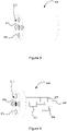
control device 200 may use one or more permanent magnets or one or more electromagnets in order to operate thecontroller 120 via themagnetic sensor 130. Thecontrol device 200 may also comprise one or more light detectors (e.g. photodiodes) in order to receive optical signals from thedisplay panel 102, thereby enabling two-way communication between thecontrol device 200 and thecontroller 120. For the purposes of explanation, two examples ofcontrol device 200 will now be described. It is appreciated that features described with reference to either example may be applied to the other example, and vice-versa. -
Figure 3 shows a first example of acontrol device 200. In this example, the control device comprises at least onepermanent magnet 201. The permanent magnet(s) 201 may be housed in a body for the user to hold. - The
control device 200 in this example generates a constant magnetic field due to the permanent magnet(s) 201. The user can move thecontrol device 200 to a location where the magnetic field of the permanent magnet(s) 201 is sensed by themagnetic sensor 130. For example, the user may position thecontrol device 200 on or near the front surface of the display panel 102 (e.g. at a location on the front surface of thedisplay panel 102 corresponding to the location of themagnetic sensor 130 on the back of the display panel 102), where the magnetic field of the at least onemagnet 201 can be detected by themagnetic sensor 130. In doing so, the user may place theexternal surface 210 of the control device 200 (i.e. the "front" of the control device 200) against the front surface of thedisplay panel 102. In some examples, thecontrol device 200 comprises a cushioning on thisexternal surface 210 for contacting the front surface of thedisplay panel 102. This can help prevent damage to thedisplay panel 102. The cushioning may be, for example, a rubber or felt cushioning, or some other soft material. - The
controller 120 controls thedisplay panel 102 based on the magnetic field sensed by themagnetic sensor 120. In this example, the magnetic field from thecontrol device 200 may be a simple "trigger" to cause thecontroller 120 to control thedisplay panel 120 in some predetermined manner (e.g. to enter the test mode as explained above). - In order to avoid the
controller 120 acting on background magnetic fields (e.g. the magnetic field of the Earth), thecontroller 120 may be configured to apply a threshold to the magnetic field sensed by themagnetic sensor 130 such that thecontroller 120 only controls thedisplay panel 102 based on magnetic fields having a signal strength above a threshold magnetic field strength. In other words, thecontroller 120 may be configured to ignore weak magnetic fields (having a strength below the threshold magnetic field strength). The threshold magnetic field strength may be set, for example, to slightly above the magnetic field strength experienced by themagnetic sensor 130 due to the magnetic field of the Earth at the location of thedisplay panel 102. In another example, the threshold magnetic field strength may be set, for example, to be slightly below the magnetic field strength experienced at themagnetic sensor 130 when thecontrol device 200 is placed on thedisplay panel 102 in the manner described above (and optionally activated, in the case of an electromagnet - seeFigure 4 below). -
Figure 4 shows a second example of acontrol device 200. In this example, thecontrol device 200 comprises at least oneelectromagnet 201, at least onelight detector 202, acontrol module 203, apower source 204, and auser interface 205. Thecontrol module 203 is operatively coupled to the electromagnet(s) 201, the light detector(s) 202, thepower source 204 and theuser interface 205. The user may position thecontrol device 200 on or near the front surface of thedisplay panel 102 in a similar manner to described above in relation toFigure 3 . Thepower source 204 is preferably an internal power source e.g. a battery. - In this example, the
control device 200 comprises a "head" and a "body". The external surface is the "front" surface of the head of thecontrol device 200. The at least oneelectromagnet magnet 201 and at least onelight detector 202 are located on the front surface of the head of thecontrol device 200. Again, there may be a cushioning provided on the external surface of thecontrol device 200 designed to contact thedisplay panel 102 in order to protect thedisplay panel 102 and thecontrol device 200. - The at least one
light detector 202 may be for example, at least one photodetector. Thelight detector 202 allows thecontrol device 200 to receive optical signals from the display panel 102 (e.g. OWC signals). - In this example, the magnetic field output by the
control device 200 is controllable by activation of the electromagnet(s) 201. Thecontrol device 200 may control the electromagnet(s) 201 to modulate one or more properties of the magnet field in order to encode a signal. For example, thecontrol device 200 may send the signals using pulse width modulation of the intensity of the magnetic field generated by the electromagnet(s) 201. Hence, thecontrol device 200 may be able to send two or more different signals to thecontroller 120 via themagnetic sensor 130. Thecontroller 120 may be configured to control thedisplay panel 102 in accordance with the specific signal received via themagnetic sensor 130. For example, thecontroller 120 may be configured to perform a first action in response to receiving a first type of signal from thecontrol device 200 and to perform a second action in response to receiving a second type of signal from thecontrol device 200. - The user may specify a particular signal to be sent to the
controller 120 by providing user input to thecontrol device 200 via theuser interface 205. Theuser interface 205 may be, for example, one or more buttons, a touch screen, etc. In response, thecontrol module 203 may control theelectromagnet 201 accordingly to output that particular signal. This means, for example, that the user can control thedisplay panel 102 to perform a desired one of many actions. E.g. the user may specify to thecontroller 120 which test image to display. - In some examples, the
controller 120 may apply a filter to the magnetic field (magnetic signals) sensed by themagnetic sensor 130 such that thecontroller 120 does not control thedisplay panel 102 based on magnetic fields having a constant magnetic field strength. That is, thecontroller 120 may only control thedisplay panel 102 in accordance with the received magnetic field if a magnetic field strength of the magnetic field (as sensed by the magnetic sensor 130) changes or has changed. An advantage of this is that constant magnetic fields are ignored, regardless of their strength. Such constant magnetic fields may result from, for example, magnets used to attach thedisplay panels 102 to one another. - Similarly to above, the
controller 120 may be configured to apply a threshold to the magnetic field (magnetic signal) sensed by themagnetic sensor 130 in order to avoid thecontroller 120 acting on background magnetic fields (e.g. the magnetic field of the Earth). In general, it is appreciated that any one or more features described in relation toFigure 3 may be applied to the examiner ofFigure 4 (and vice-versa). -
Figure 5 shows schematically aPCBA 500 of adisplay panel 102. In this example there are four layers of PCB. In order starting from the front of the display panel 102 (the top inFigure 5 ), these are: a first PCB layer 502, asecond PCB layer 504, athird PCB layer 506, and afourth PCB layer 508. The PCB layers 502, 504, 506 and 508 are insulated from one another by insulatinglayers layers - In this example, the first PCB layer 502 and
fourth PCB layer 508 are signal layers comprising one or more electronic components. A front plating build up 501 is provided on the top of the first PCB layer 502 and a rear plating build up 509 is provided on the bottom of thefourth PCB layer 508. The front plating build up 501 and rear plating build up 509 are made of a conducting material (e.g. metal, such as copper) which is to be etched to configure the first PCB layer 502 andfourth PCT layer 508 accordingly. - The
aforementioned display elements 103 may be located on the first PCB layer 502. - The aforementioned
magnetic sensor 130 may be located on thefourth PCB layer 508. Hence, as illustrated by a dotted arrow inFigure 5 , a magnetic field generated at the front of thedisplay panel 102 needs to permeate through all thePCBA 500 located above thefourth PCB layer 508 in order to be detected by themagnetic sensor 130, i.e. through the front plating build up 501, the first PCB layer 502, the first insulatinglayer 503, thesecond PCB layer 504, the second insulatinglayer 506, thethird PCB layer 506, and the third insulatinglayer 507. This is why, for example, many other, non-magnetic types of signal can be blocked from reaching the rear of thedisplay panel 102 and why a magnetic signal is advantageously used in the present invention. - It will be understood that the processor or processing system or circuitry referred to herein may in practice be provided by a single chip or integrated circuit or plural chips or integrated circuits, optionally provided as a chipset, an application-specific integrated circuit (ASIC), field-programmable gate array (FPGA), digital signal processor (DSP), graphics processing units (GPUs), etc. The chip or chips may comprise circuitry (as well as possibly firmware) for embodying at least one or more of a data processor or processors, a digital signal processor or processors, baseband circuitry and radio frequency circuitry, which are configurable so as to operate in accordance with the exemplary embodiments. In this regard, the exemplary embodiments may be implemented at least in part by computer software stored in (non-transitory) memory and executable by the processor, or by hardware, or by a combination of tangibly stored software and hardware (and tangibly stored firmware).
- Reference is made herein to data storage for storing data. This may be provided by a single device or by plural devices. Suitable devices include for example a hard disk and non-volatile semiconductor memory (including for example a solid-state drive or SSD).
- Although at least some aspects of the embodiments described herein with reference to the drawings comprise computer processes performed in processing systems or processors, the invention also extends to computer programs, particularly computer programs on or in a carrier, adapted for putting the invention into practice. The program may be in the form of non-transitory source code, object code, a code intermediate source and object code such as in partially compiled form, or in any other non-transitory form suitable for use in the implementation of processes according to the invention. The carrier may be any entity or device capable of carrying the program. For example, the carrier may comprise a storage medium, such as a solid-state drive (SSD) or other semiconductor-based RAM; a ROM, for example a CD ROM or a semiconductor ROM; a magnetic recording medium, for example a floppy disk or hard disk; optical memory devices in general; etc.
- The examples described herein are to be understood as illustrative examples of embodiments of the invention. Further embodiments and examples are envisaged. Any feature described in relation to any one example or embodiment may be used alone or in combination with other features. In addition, any feature described in relation to any one example or embodiment may also be used in combination with one or more features of any other of the examples or embodiments, or any combination of any other of the examples or embodiments. Furthermore, equivalents and modifications not described herein may also be employed within the scope of the invention, which is defined in the claims.
Claims (15)
- A display panel (102), the display panel (102) having a front surface and an opposed rear surface, the display panel comprising:a display screen at the front surface for displaying images, the display screen comprising a plurality of display elements (103);a magnetic sensor (130) located behind the front surface, the magnetic sensor (130) being constructed and arranged to sense a magnetic field through the front surface of the display panel (102); anda controller (120), behind the front surface, configured to control the display panel (102) based on the magnetic field sensed by the magnetic sensor (130) through the front surface of the display panel (102).
- A display panel (102) according to claim 1, wherein the controller is configured to control the display panel (102) to enter a test mode based on the magnetic field sensed by the magnetic sensor (130) through the front surface of the display panel (102).
- A display panel (102) according to claim 2, wherein said test mode comprises controlling the display panel (102) to display a predetermined image via the display screen.
- A display panel (102) according to claim 2 or claim 3, wherein said test mode comprises controlling at least one of the display elements (103) to output the current value of a one or more operating parameters of the display panel (102) via an optical wireless communication, OWC, signal.
- A display panel (102) according to any of claims 2 to 4, wherein said test mode comprises one or more of a debug procedure, or a restart of the display panel (102).
- A display panel (102) according to any of claims 1 to 5, wherein the magnetic sensor is a Hall effect sensor.
- A display panel (102) according to any of claims 1 to 6, wherein the controller (120) is configured to apply a threshold to the magnetic field sensed by the magnetic sensor (130) such that the controller (120) only controls the display panel (102) based on a magnetic field having a magnetic field strength above a threshold magnetic field strength.
- A display panel (102) according any of claims 1 to 7, wherein the controller (120) is configured to apply a filter to the magnetic field sensed by the magnetic sensor (130) such that the controller (120) does not control the display panel (102) based on a magnetic field having a constant magnetic field strength.
- A display panel (102) according to any of claims 1 to 8, wherein the display panel (102) is a bezel-less display having no bezel at the front surface.
- A display panel (102) according to any of claims 1 to 9, wherein the display panel (102) is an LED panel in which the plurality of display elements (130) is a plurality of LEDs.
- A display wall (100) comprising a plurality of display panels, at least one of the display panels being the display panel (102) of any of claims 1 to 10.
- A method of controlling a display panel (102), the display panel (102) having a front surface for displaying images, and an opposed rear surface, the method comprising:sensing, by a magnetic sensor (130) located behind the front surface of the display panel (102), a magnetic field transmitted through the front surface of the display panel (102); andcontrolling the display panel (102) in accordance with the magnetic field sensed by the magnetic sensor (130).
- A control device (200) for controlling a display panel (102), the control device (200) comprising:at least one magnet (201) for transmitting a magnetic field through a front surface of the display panel (102) for detection by a magnetic sensor (130) located behind the front surface of the display panel (102); andat least one light detector (202) for detecting optical signals output at the front surface of the display panel (102).
- A control device (200) according to claim 13, wherein the at least one magnet (201) is an electromagnet, and the control device (200) is configured to control the electromagnetic (201) to output magnetic field signals via pulse width modulation.
- A control device (200) according to claim 13 or claim 14, comprising a cushioning on at least one external surface (210) of the control device (200) for contacting the front surface of a said display panel (102).
Priority Applications (1)
| Application Number | Priority Date | Filing Date | Title |
|---|---|---|---|
| EP21189915.8A EP4131227A1 (en) | 2021-08-05 | 2021-08-05 | Display panel control |
Applications Claiming Priority (1)
| Application Number | Priority Date | Filing Date | Title |
|---|---|---|---|
| EP21189915.8A EP4131227A1 (en) | 2021-08-05 | 2021-08-05 | Display panel control |
Publications (1)
| Publication Number | Publication Date |
|---|---|
| EP4131227A1 true EP4131227A1 (en) | 2023-02-08 |
Family
ID=77226725
Family Applications (1)
| Application Number | Title | Priority Date | Filing Date |
|---|---|---|---|
| EP21189915.8A Withdrawn EP4131227A1 (en) | 2021-08-05 | 2021-08-05 | Display panel control |
Country Status (1)
| Country | Link |
|---|---|
| EP (1) | EP4131227A1 (en) |
Cited By (1)
| Publication number | Priority date | Publication date | Assignee | Title |
|---|---|---|---|---|
| WO2024203693A1 (en) * | 2023-03-30 | 2024-10-03 | Sony Group Corporation | Display system |
Citations (1)
| Publication number | Priority date | Publication date | Assignee | Title |
|---|---|---|---|---|
| US20100259375A1 (en) * | 2009-04-13 | 2010-10-14 | Bran Ferren | Customizable and reconfigurable virtual instrument panel |
-
2021
- 2021-08-05 EP EP21189915.8A patent/EP4131227A1/en not_active Withdrawn
Patent Citations (1)
| Publication number | Priority date | Publication date | Assignee | Title |
|---|---|---|---|---|
| US20100259375A1 (en) * | 2009-04-13 | 2010-10-14 | Bran Ferren | Customizable and reconfigurable virtual instrument panel |
Cited By (1)
| Publication number | Priority date | Publication date | Assignee | Title |
|---|---|---|---|---|
| WO2024203693A1 (en) * | 2023-03-30 | 2024-10-03 | Sony Group Corporation | Display system |
Similar Documents
| Publication | Publication Date | Title |
|---|---|---|
| EP3089001B1 (en) | Screen assembly of mobile device and mobile device | |
| US10712992B2 (en) | Modular display apparatus and method for controlling thereof | |
| KR101703856B1 (en) | Integrated visual notification system in an accessory device | |
| EP2660710B1 (en) | Automatic detection method of video wall arrangement and video wall system using the same | |
| US20220188059A1 (en) | Display apparatus and method for controlling thereof | |
| US9760156B2 (en) | Display apparatus, display system having plural display apparatuses, and method for controlling the display system | |
| EP1837742A2 (en) | Display device, sensor panel, position-detecting device position-inputting device and computer system. | |
| US8576183B2 (en) | Devices and methods for controlling both LED and touch sense elements via a single IC package pin | |
| US10685608B2 (en) | Display device and displaying method | |
| EP2256597B1 (en) | Information input device, information input method, information input-output device, storage medium, and electronic unit | |
| CN107979771B (en) | Electronic apparatus and method of controlling the same | |
| KR102382049B1 (en) | Modular display appatus and method for controlling thereof | |
| KR20190068123A (en) | Display apparatus and controlling method thereof | |
| US10303285B2 (en) | Sensor device for a display | |
| EP4095673A1 (en) | Display apparatus and method for controlling thereof | |
| CN108733196A (en) | Display base plate, display device and its operating method | |
| CN108334228B (en) | Touch screen, driving method thereof and touch device | |
| US20220244901A1 (en) | Tiling Display System | |
| CN110580879A (en) | A terminal device and display control method | |
| EP2192573A2 (en) | Display apparatus using external device connection unit and method of determining format of input image thereof | |
| CN108965536A (en) | Mobile terminal | |
| CN106095206A (en) | Interference mitigation in capacitance sensing apparatus | |
| KR20190033407A (en) | Electronic device and method for preventing deterioration of pixel | |
| CN104238836A (en) | Touch display device and driving and sensing method thereof | |
| TR2021012400A2 (en) | IMAGING PANEL CONTROL |
Legal Events
| Date | Code | Title | Description |
|---|---|---|---|
| PUAI | Public reference made under article 153(3) epc to a published international application that has entered the european phase |
Free format text: ORIGINAL CODE: 0009012 |
|
| STAA | Information on the status of an ep patent application or granted ep patent |
Free format text: STATUS: THE APPLICATION HAS BEEN PUBLISHED |
|
| AK | Designated contracting states |
Kind code of ref document: A1 Designated state(s): AL AT BE BG CH CY CZ DE DK EE ES FI FR GB GR HR HU IE IS IT LI LT LU LV MC MK MT NL NO PL PT RO RS SE SI SK SM TR |
|
| STAA | Information on the status of an ep patent application or granted ep patent |
Free format text: STATUS: THE APPLICATION IS DEEMED TO BE WITHDRAWN |
|
| 18D | Application deemed to be withdrawn |
Effective date: 20230809 |