EP4131218A1 - Display apparatus and display device - Google Patents
Display apparatus and display device Download PDFInfo
- Publication number
- EP4131218A1 EP4131218A1 EP20750155.2A EP20750155A EP4131218A1 EP 4131218 A1 EP4131218 A1 EP 4131218A1 EP 20750155 A EP20750155 A EP 20750155A EP 4131218 A1 EP4131218 A1 EP 4131218A1
- Authority
- EP
- European Patent Office
- Prior art keywords
- scroll
- flexible screen
- display device
- frame
- sliding block
- Prior art date
- Legal status (The legal status is an assumption and is not a legal conclusion. Google has not performed a legal analysis and makes no representation as to the accuracy of the status listed.)
- Granted
Links
Images




Classifications
-
- G—PHYSICS
- G09—EDUCATION; CRYPTOGRAPHY; DISPLAY; ADVERTISING; SEALS
- G09F—DISPLAYING; ADVERTISING; SIGNS; LABELS OR NAME-PLATES; SEALS
- G09F9/00—Indicating arrangements for variable information in which the information is built-up on a support by selection or combination of individual elements
- G09F9/30—Indicating arrangements for variable information in which the information is built-up on a support by selection or combination of individual elements in which the desired character or characters are formed by combining individual elements
- G09F9/301—Indicating arrangements for variable information in which the information is built-up on a support by selection or combination of individual elements in which the desired character or characters are formed by combining individual elements flexible foldable or roll-able electronic displays, e.g. thin LCD, OLED
-
- G—PHYSICS
- G09—EDUCATION; CRYPTOGRAPHY; DISPLAY; ADVERTISING; SEALS
- G09F—DISPLAYING; ADVERTISING; SIGNS; LABELS OR NAME-PLATES; SEALS
- G09F9/00—Indicating arrangements for variable information in which the information is built-up on a support by selection or combination of individual elements
- G09F9/30—Indicating arrangements for variable information in which the information is built-up on a support by selection or combination of individual elements in which the desired character or characters are formed by combining individual elements
- G09F9/33—Indicating arrangements for variable information in which the information is built-up on a support by selection or combination of individual elements in which the desired character or characters are formed by combining individual elements being semiconductor devices, e.g. diodes
- G09F9/335—Indicating arrangements for variable information in which the information is built-up on a support by selection or combination of individual elements in which the desired character or characters are formed by combining individual elements being semiconductor devices, e.g. diodes being organic light emitting diodes [OLED]
-
- G—PHYSICS
- G06—COMPUTING OR CALCULATING; COUNTING
- G06F—ELECTRIC DIGITAL DATA PROCESSING
- G06F3/00—Input arrangements for transferring data to be processed into a form capable of being handled by the computer; Output arrangements for transferring data from processing unit to output unit, e.g. interface arrangements
- G06F3/01—Input arrangements or combined input and output arrangements for interaction between user and computer
- G06F3/03—Arrangements for converting the position or the displacement of a member into a coded form
- G06F3/041—Digitisers, e.g. for touch screens or touch pads, characterised by the transducing means
- G06F3/0412—Digitisers structurally integrated in a display
-
- G—PHYSICS
- G06—COMPUTING OR CALCULATING; COUNTING
- G06F—ELECTRIC DIGITAL DATA PROCESSING
- G06F3/00—Input arrangements for transferring data to be processed into a form capable of being handled by the computer; Output arrangements for transferring data from processing unit to output unit, e.g. interface arrangements
- G06F3/01—Input arrangements or combined input and output arrangements for interaction between user and computer
- G06F3/048—Interaction techniques based on graphical user interfaces [GUI]
- G06F3/0487—Interaction techniques based on graphical user interfaces [GUI] using specific features provided by the input device, e.g. functions controlled by the rotation of a mouse with dual sensing arrangements, or of the nature of the input device, e.g. tap gestures based on pressure sensed by a digitiser
- G06F3/0488—Interaction techniques based on graphical user interfaces [GUI] using specific features provided by the input device, e.g. functions controlled by the rotation of a mouse with dual sensing arrangements, or of the nature of the input device, e.g. tap gestures based on pressure sensed by a digitiser using a touch-screen or digitiser, e.g. input of commands through traced gestures
- G06F3/04886—Interaction techniques based on graphical user interfaces [GUI] using specific features provided by the input device, e.g. functions controlled by the rotation of a mouse with dual sensing arrangements, or of the nature of the input device, e.g. tap gestures based on pressure sensed by a digitiser using a touch-screen or digitiser, e.g. input of commands through traced gestures by partitioning the display area of the touch-screen or the surface of the digitising tablet into independently controllable areas, e.g. virtual keyboards or menus
-
- H—ELECTRICITY
- H05—ELECTRIC TECHNIQUES NOT OTHERWISE PROVIDED FOR
- H05K—PRINTED CIRCUITS; CASINGS OR CONSTRUCTIONAL DETAILS OF ELECTRIC APPARATUS; MANUFACTURE OF ASSEMBLAGES OF ELECTRICAL COMPONENTS
- H05K5/00—Casings, cabinets or drawers for electric apparatus
- H05K5/0017—Casings, cabinets or drawers for electric apparatus with operator interface units
-
- H—ELECTRICITY
- H05—ELECTRIC TECHNIQUES NOT OTHERWISE PROVIDED FOR
- H05K—PRINTED CIRCUITS; CASINGS OR CONSTRUCTIONAL DETAILS OF ELECTRIC APPARATUS; MANUFACTURE OF ASSEMBLAGES OF ELECTRICAL COMPONENTS
- H05K5/00—Casings, cabinets or drawers for electric apparatus
- H05K5/02—Details
- H05K5/0217—Mechanical details of casings
-
- H—ELECTRICITY
- H05—ELECTRIC TECHNIQUES NOT OTHERWISE PROVIDED FOR
- H05K—PRINTED CIRCUITS; CASINGS OR CONSTRUCTIONAL DETAILS OF ELECTRIC APPARATUS; MANUFACTURE OF ASSEMBLAGES OF ELECTRICAL COMPONENTS
- H05K7/00—Constructional details common to different types of electric apparatus
- H05K7/14—Mounting supporting structure in casing or on frame or rack
-
- H—ELECTRICITY
- H10—SEMICONDUCTOR DEVICES; ELECTRIC SOLID-STATE DEVICES NOT OTHERWISE PROVIDED FOR
- H10K—ORGANIC ELECTRIC SOLID-STATE DEVICES
- H10K2102/00—Constructional details relating to the organic devices covered by this subclass
- H10K2102/301—Details of OLEDs
- H10K2102/311—Flexible OLED
-
- H—ELECTRICITY
- H10—SEMICONDUCTOR DEVICES; ELECTRIC SOLID-STATE DEVICES NOT OTHERWISE PROVIDED FOR
- H10K—ORGANIC ELECTRIC SOLID-STATE DEVICES
- H10K50/00—Organic light-emitting devices
- H10K50/80—Constructional details
- H10K50/84—Passivation; Containers; Encapsulations
- H10K50/841—Self-supporting sealing arrangements
Definitions
- the present disclosure relates to the field of displays, in particular to a display device and a display equipment.
- OLEDs organic light emitting diodes
- the present disclosure provides a display device and a display equipment for solving technical problems that a foldable device and a flexible device in the prior art cannot reduce a space occupied by the foldable device and the flexible device when realizing a large-size screen.
- An embodiment of the present disclosure provides a display device including a frame and a flexible screen.
- a width of the frame is adjustable.
- the flexible screen is installed on the frame, and a width of the flexible screen is adjustable.
- the frame includes a case, a first bracket, and a second bracket.
- the case is formed with a plurality of sliding chutes parallel to each other.
- Each sliding chute includes a first chute mouth and a second chute mouth opposite to the first chute mouth.
- the first bracket includes a first sliding block, and the first sliding block is slidably inserted into at least one sliding chute, and the first sliding block passes through the first chute mouth of the sliding chute.
- the second bracket includes a second sliding block, and the second sliding block is slidably inserted into at least one sliding chute, and the second sliding block passes through the second chute mouth of the sliding chute.
- the first bracket includes a first box and a first scroll rotatably connected to two opposite inner walls of the first box, and a central axis of the first scroll is perpendicular to an extending direction of the sliding chutes.
- the second bracket includes a second box and a second scroll rotatably connected to two opposite inner walls of the second box, and a central axis of the second scroll is parallel to the central axis of the first scroll.
- the display device further includes a first motor and a second motor.
- a rotor of the first motor is connected to the first scroll, and a rotor of the second motor is connected to the second scroll.
- the flexible screen includes a central display area, a first extension area, and a second extension area, which are formed integrally.
- the central display area includes a first side and a second side opposite to the first side.
- One end of the first extension area is connected to the first side of the central display area, and another end of the first extension area is spirally sleeved on an outer wall of the first scroll and is connected to the first scroll.
- One end of the second extension area is connected to the second side of the central display area, and another end of the second extension area is spirally sleeved on an outer wall of the second scroll and is connected to the second scroll.
- the present disclosure also provides a display equipment including the display device as mentioned above.
- the display equipment further includes a first display device and a second display device.
- the first display device includes a first frame and a first flexible screen.
- the second display device includes a second frame and a second flexible screen, and the first flexible screen and the second flexible screen are formed integrally.
- the display equipment further includes a connecting section, and two ends of the connecting section are rotatably connected to the first frame and the second frame, respectively.
- the connecting section includes a shaft, a first connecting piece, and a second connecting piece.
- One end of the first connecting piece is rotatably connected to the shaft, and another end of the first connecting piece is fixedly connected to the first frame.
- One end of the second connecting piece is rotatably connected to the shaft, and another end of the second connecting piece is fixedly connected to the second frame.
- the display equipment further includes a third flexible screen disposed on a surface of the connecting section, and the third flexible screen is formed integrally with the first flexible screen and the second flexible screen.
- placing a part of the flexible screen inside the sliding block can reduce a size of the display device and is easy to carry.
- the flexible screen can be fully opened, which increases a display area and improves the user's visual experience.
- Two display devices are connected through the connecting section to make them into a display equipment with an inverted "H" shape.
- one of the display devices realizes a display function of the display panel, and the other display device realizes a function of a touchable keyboard, so as to realize a transformation of a mobile phone and a notebook computer.
- a structure in which a first feature is "on" or “below” a second feature may include an embodiment in which the first feature is in direct contact with the second feature, and may also include an embodiment in which the first feature and the second feature are not in direct contact with each other, but are contacted via an additional feature formed therebetween.
- a first feature "on,” “above,” or “on top of” a second feature may include an embodiment in which the first feature is right or obliquely “on,” “above,” or “on top of” the second feature, or just means that the first feature is at a height higher than that of the second feature; while a first feature “below,” “under,” or “on bottom of' a second feature may include an embodiment in which the first feature is right or obliquely “below,” “under,” or “on bottom of” the second feature, or just means that the first feature is at a height lower than that of the second feature.
- FIG. 2 is schematic diagram showing a display device in a collapsed state of the first embodiment
- FIG. 3 is schematic diagram showing the display device in an extended state of the first embodiment
- FIG. 4 is a cross-sectional view of the display device of the first embodiment.
- a display device 10 includes a frame 100 and a flexible screen 200.
- a width of the frame 100 is adjustable.
- the flexible screen 200 is installed on the frame 100, and a width of the flexible screen 200 may change as the width of the frame changes.
- FIG. 1 is a schematic diagram of the frame of the first embodiment.
- the frame 100 includes a case 101, a first bracket 102, and a second bracket 103.
- the case 101 is provided with a plurality sliding chutes 1011 parallel to each other. Two ends of each sliding chutes 1011 include a first chute mouth 1012 and a second chute mouth 1013. A direction of the openings of the first chute mouth 1012 and the second chute mouth 1013 is a width adjustment direction of the frame 100.
- the first bracket 102 includes a first sliding block 1021 and a first box 1022.
- the first sliding block 1021 is an elongated sliding block, one end of which is connected to one side of the first box 1022, and the other end of which is slidably inserted into the sliding chute 1011 through the first chute mouth 1012.
- distances between two adjacent first sliding blocks 1021 are equal, and the two adjacent first sliding blocks 1021 are separated by at least one sliding chute 1011.
- the first sliding block 1021 is connected to the side of the first box 1022. When the first box 1022 moves away from the case 101, the first sliding block 1021 slides in a direction toward the first chute mouth 1012 of the sliding chutes 1011.
- a brake locking mechanism is provided between the first sliding block 1021 and the corresponding sliding chute 1011 to limit a distance that the first sliding block 1021 slides out of the sliding chute 1011 and a position of the first sliding block 1021 so that it is in a stable state.
- FIG. 6 is a schematic view of a flexible lock in a braking position of the first embodiment
- FIG. 7 is a schematic view of a flexible lock in a return position of the first embodiment
- FIG. 8 is a schematic view of a flexible lock in a retracted position of the first embodiment.
- the flexible lock 300 serves as a braking device of first sliding block 1021 and sliding chute 1011.
- the flexible lock 300 includes a lock tongue 301 and a latch 302.
- the lock tongue 301 is a flexible lock tongue and is elastically arranged inside the first sliding block 1021.
- a shape of the lock tongue 301 is a fan-shaped protruding structure, including a plane 3011 and a curved surface 3012.
- the lock tongue 301 overcomes an elastic force and is completely disposed on an inside of the first sliding block 1021.
- One side of the curved surface 3012 of the lock tongue 301 faces the sliding chute 1011 and is always tangent to an inner wall of the sliding chute 1011.
- the lock tongue 301 pops out from the inside of the first sliding block 1021, and one side of the plane 3011 of the lock tongue 301 pops out from the inside of the first sliding block 1021 and abuts a side wall of the latch 302, thereby achieving a purpose of braking the first sliding block 1021.
- a relative position of the lock tongue 301 and the latch 302 changes as the first sliding block 1021 slides on the sliding chute 1011.
- a side wall of the latch 302 away from the plane 3011 abuts the curved surface 3012. Due to a curvature of the curved surface 3012, the lock tongue 301 will be retracted into the first sliding block 1021 under an external force of the latch 302 to overcome an elastic modulus.
- the latch 302 is located at the sliding chute 1011 near the first chute mouth 1012. In order to ensure that the first sliding block 1021 can slide freely within the sliding chute 1011, there is a safe distance between the latch 302 and the first chute mouth 1012, thereby preventing the first sliding block 1021 from completely separating from the sliding chute 1011 during the sliding process.
- the first box 1022 includes a first opening 10221 and a first chamber 10222 corresponding to the first opening 10221.
- An outer wall of the first box 10221 is fixedly connected to the first sliding block 1021, so that a position of the first box 10221 relative to the first chute mouth 1012 can change as the first sliding block 1021 moves within the sliding chute 1011.
- the first bracket 103 also includes a first scroll 1023.
- the first scroll 1023 is rotatably connected to the first chamber 10222. Specifically, both ends of an axial of the first scroll 1023 are rotatably connected to side walls of the first chamber 10222 corresponding to the first chute mouth 1012. There is a gap between an outer wall of the first scroll 1023 and an inner wall of the first chamber 1022.
- the flexible screen 300 includes a central display area 301, a first extension area 302, and a second extension area 303.
- the central display area 301 is disposed directly above the case 101.
- the sliding chute 1011 adopts a U-shaped sliding chute, that is, the sliding chute 1011 has an opening 1014 in addition to the first chute mouth 1012 and the second chute mouth 1013.
- a direction of the opening 1014 is a direct direction when a user uses the display device 10, that is, the case 101 is near the central display area 301.
- the central display area 301 also includes a first side 3011 and a second side 3012.
- the first side 3011 is connected to one end of the first extension area 302.
- the connection between the first extension area 302 and the first side 3011 is always under tension.
- the second side 3012 is connected to one end of the second extension area 303.
- the connection between the second extension area 303 and the second side 3012 is always under tension, and the central display area 301 is always under tension.
- One end of the first extension area 302 away from the first side 3011 passes through the first opening 10221 and is spirally sleeved on an outer wall of the first scroll 1023 and connected to the outer wall of the first scroll 1023.
- the first extension area 302 spirals away from an inside of the first chamber 10222 and gradually flattens on the first sliding block 1021 exposed outside the sliding chute 1011 until the first sliding block 1021 reaches a braking distance.
- the first extension area 302 is spirally sleeved on the scroll 1023 with the rotation direction of the scroll 1023 and placed in the first chamber 10222.
- the second bracket 103 includes a second sliding block 1031 and a second box 1032.
- the second sliding block 1031 is an elongated sliding block, one end of which is connected to one side of the second box 1032 and the other end of which is slidably inserted into the sliding chute 1011 through the second chute mouth 1032.
- the same device as the flexible lock 300 is also arranged between the second sliding block 1031 and the sliding chute 1011.
- the latch corresponding to the lock tongue set on the second sliding block 1031 is disposed near the second chute mouth 1032 of the sliding chute 1011.
- a sliding direction of the first sliding block 1021 is opposite to that of the second sliding block 1031.
- the first sliding block 1021 and the second sliding block 1031 are alternatively inserted into the sliding chutes 1011. It is beneficial for the first bracket 102 and the second bracket 103 to be evenly stressed, thereby improving a lifespan of the display device 10.
- the display device 10 further includes a first motor and a second motor.
- the first motor has a first rotor.
- the first rotor is connected to the first scroll 1023 to control a rotation of the first scroll 1023.
- a rotation direction of the first rotor includes a first direction and a second direction.
- the second motor has a second rotor.
- the second rotor is connected to the second scroll 1033 to control a rotation of the second scroll 1033.
- a rotation direction of the second rotor includes a third direction and a fourth direction.
- the first direction and the third direction are parallel to each other and opposite directions.
- the second direction and the fourth direction are parallel to each other and opposite directions.
- FIG. 9 is a partial schematic diagram of a display equipment of a second embodiment
- FIG. 10 is schematic diagram showing the display equipment in a collapsed state of the second embodiment
- FIG. 11 is schematic diagram showing the display equipment in an extended state of the second embodiment.
- the display equipment includes a first display device 11, a second display device 12, and a connecting section 13.
- the connecting section 13 includes a central axis.
- the first display device 11 and the second display device 12 are symmetrical about the central axis.
- the first display device 11 has the same structure as the display device 10 in the first embodiment.
- FIG. 12 is schematic diagram of a connecting section of the second embodiment and FIG. 13 is cross-sectional view of the connecting section of the second embodiment.
- the connecting section 13 includes a shaft 131, a first connecting piece 132, and a second connecting piece 133. An axis of the shaft 131 coincides with the central axis of the connecting section 13.
- the first connecting piece 132 includes a first connection body 1321 and a first connecting bracket 1322.
- a shape of the first connection body 1321 is a hollow cylinder.
- An inner diameter of the first connection body 1321 matches an outer diameter of the shaft 132.
- the first connection body 1321 is sleeved on the shaft 132.
- a flat key is also provided between the first connection body 1321 and the shaft 132 to axially fix the first connection body 1321 and the shaft 132, thereby achieving a function of transmitting torque.
- One end of the first connecting bracket 1322 is connected to an outer wall of the first connection body 1321, and the other end of which is connected to one end of the case 101 of the first display device 11. Specifically, the end is connected to a side of the case 101 parallel to a sliding direction of the sliding chute 1011.
- the second connecting piece 133 includes a second connection body and a second connecting bracket 1332.
- the second connection body includes a first connection cavity 13311 and a second connection cavity 13312. Openings of the first connection cavity 13311 and the second connection cavity 13312 are oppositely arranged. A distance between the first connection cavity 13311 and the second connection cavity 13312 is greater than an axial distance of the first connection body 1321 on the connecting shaft 131.
- a rotation mode of the shaft 131 includes a gear rotation, a belt drive, or motor rotation, which is not limited here.
- One end of the second connecting bracket 1332 is connected to the second connection body 1331, and the other end of which is connected to the second display device 12.
- the second flexible screen 1301 is formed integrally with the flexible screen 100 of the first display device 11.
- the other end of the second flexible screen 1301 is formed integrally with the flexible screen 100 of the second display device 12, thereby ensuring a display quality of the display equipment 1.
Landscapes
- Engineering & Computer Science (AREA)
- Physics & Mathematics (AREA)
- Theoretical Computer Science (AREA)
- General Physics & Mathematics (AREA)
- Microelectronics & Electronic Packaging (AREA)
- General Engineering & Computer Science (AREA)
- Human Computer Interaction (AREA)
- Optics & Photonics (AREA)
- Devices For Indicating Variable Information By Combining Individual Elements (AREA)
Abstract
Description
- The present disclosure relates to the field of displays, in particular to a display device and a display equipment.
- At present, organic light emitting diodes (OLEDs) have attracted extensive attention due to their bendable and flexible properties. By folding or rolling up the OLED, a space occupied by a large-sized screen can be reduced, making it more portable. Therefore, foldable display equipment and flexible display equipment are main research directions of the flexible OLED.
- The present disclosure provides a display device and a display equipment for solving technical problems that a foldable device and a flexible device in the prior art cannot reduce a space occupied by the foldable device and the flexible device when realizing a large-size screen.
- An embodiment of the present disclosure provides a display device including a frame and a flexible screen. A width of the frame is adjustable. The flexible screen is installed on the frame, and a width of the flexible screen is adjustable.
- Furthermore, the frame includes a case, a first bracket, and a second bracket. The case is formed with a plurality of sliding chutes parallel to each other. Each sliding chute includes a first chute mouth and a second chute mouth opposite to the first chute mouth. The first bracket includes a first sliding block, and the first sliding block is slidably inserted into at least one sliding chute, and the first sliding block passes through the first chute mouth of the sliding chute. The second bracket includes a second sliding block, and the second sliding block is slidably inserted into at least one sliding chute, and the second sliding block passes through the second chute mouth of the sliding chute.
- Furthermore, the first bracket includes a first box and a first scroll rotatably connected to two opposite inner walls of the first box, and a central axis of the first scroll is perpendicular to an extending direction of the sliding chutes. The second bracket includes a second box and a second scroll rotatably connected to two opposite inner walls of the second box, and a central axis of the second scroll is parallel to the central axis of the first scroll.
- Furthermore, the display device further includes a first motor and a second motor. A rotor of the first motor is connected to the first scroll, and a rotor of the second motor is connected to the second scroll.
- Furthermore, the flexible screen includes a central display area, a first extension area, and a second extension area, which are formed integrally. The central display area includes a first side and a second side opposite to the first side. One end of the first extension area is connected to the first side of the central display area, and another end of the first extension area is spirally sleeved on an outer wall of the first scroll and is connected to the first scroll. One end of the second extension area is connected to the second side of the central display area, and another end of the second extension area is spirally sleeved on an outer wall of the second scroll and is connected to the second scroll.
- The present disclosure also provides a display equipment including the display device as mentioned above.
- Furthermore, the display equipment further includes a first display device and a second display device. The first display device includes a first frame and a first flexible screen. The second display device includes a second frame and a second flexible screen, and the first flexible screen and the second flexible screen are formed integrally.
- Furthermore, the display equipment further includes a connecting section, and two ends of the connecting section are rotatably connected to the first frame and the second frame, respectively.
- Furthermore, the connecting section includes a shaft, a first connecting piece, and a second connecting piece. One end of the first connecting piece is rotatably connected to the shaft, and another end of the first connecting piece is fixedly connected to the first frame. One end of the second connecting piece is rotatably connected to the shaft, and another end of the second connecting piece is fixedly connected to the second frame.
- Furthermore, the display equipment further includes a third flexible screen disposed on a surface of the connecting section, and the third flexible screen is formed integrally with the first flexible screen and the second flexible screen.
- In the display device and the display equipment of the present disclosure, placing a part of the flexible screen inside the sliding block can reduce a size of the display device and is easy to carry. When in use, the flexible screen can be fully opened, which increases a display area and improves the user's visual experience. Two display devices are connected through the connecting section to make them into a display equipment with an inverted "H" shape. Moreover, by fully extending the flexible screen, one of the display devices realizes a display function of the display panel, and the other display device realizes a function of a touchable keyboard, so as to realize a transformation of a mobile phone and a notebook computer.
- The following describes the specific embodiments of the present disclosure in detail with reference to the accompanying drawings, which will make the technical solutions of the present disclosure and other beneficial effects obvious.
-
FIG. 1 is a schematic diagram of a frame of a first embodiment. -
FIG. 2 is schematic diagram showing a display device in a collapsed state of the first embodiment. -
FIG. 3 is schematic diagram showing the display device in an extended state of the first embodiment. -
FIG. 4 is a cross-sectional view of the display device of the first embodiment. -
FIG. 5 is a side view of the display device of the first embodiment. -
FIG. 6 is a schematic view of a flexible lock in a braking position of the first embodiment. -
FIG. 7 is a schematic view of a flexible lock in a return position of the first embodiment. -
FIG. 8 is a schematic view of a flexible lock in a retracted position of the first embodiment. -
FIG. 9 is a partial schematic diagram of a display equipment of a second embodiment. -
FIG. 10 is schematic diagram showing the display equipment in a collapsed state of the second embodiment. -
FIG. 11 is schematic diagram showing the display equipment in an extended state of the second embodiment. -
FIG. 12 is schematic diagram of a connecting section of the second embodiment. -
FIG. 13 is cross-sectional view of the connecting section of the second embodiment. - In the drawings:
- 10 display device; 100 frame;
- 200 flexible screen; 101 case;
- 102 first bracket; 103 second bracket;
- 1011 sliding chutes; 1012 first chute mouth;
- 1013 second chute mouth; 1021 first sliding block;
- 1022 first box; 300 flexible lock;
- 301 lock tongue; 302 latch;
- 3011 plane; 3012 curved surface;
- 1032 second box; 10221 first opening;
- 10222 first chamber; 1023 first scroll;
- 10321 second opening; 10322 second chamber;
- 1033 second scroll; 301 central display area;
- 302 first extension area; 303 second extension area;
- 11 first display device; 12 second display device;
- 131 shaft; 132 first connecting piece;
- 133 second connecting piece; 13 connecting section;
- 1321 first connection body; 1322 first connecting bracket;
- 1332 second connecting bracket; 13311 first connection cavity;
- 13312 second connection cavity
- In order to more clearly describe the technical solutions of the embodiments of the present disclosure, accompanying drawings to be used in the detailed description of the disclosure will be briefly described hereinbelow. Obviously, the accompanying drawings described hereinbelow only illustrate some of the embodiments of the present disclosure, and those of ordinary skill in the art can also obtain other accompanying drawings therefrom without the need of making inventive efforts.
- In the present disclosure, unless specified or limited otherwise, a structure in which a first feature is "on" or "below" a second feature may include an embodiment in which the first feature is in direct contact with the second feature, and may also include an embodiment in which the first feature and the second feature are not in direct contact with each other, but are contacted via an additional feature formed therebetween. Furthermore, a first feature "on," "above," or "on top of" a second feature may include an embodiment in which the first feature is right or obliquely "on," "above," or "on top of" the second feature, or just means that the first feature is at a height higher than that of the second feature; while a first feature "below," "under," or "on bottom of' a second feature may include an embodiment in which the first feature is right or obliquely "below," "under," or "on bottom of" the second feature, or just means that the first feature is at a height lower than that of the second feature.
- Referring to
FIG. 2 ,fig. 3, and FIG. 4 ,FIG. 2 is schematic diagram showing a display device in a collapsed state of the first embodiment,FIG. 3 is schematic diagram showing the display device in an extended state of the first embodiment, andFIG. 4 is a cross-sectional view of the display device of the first embodiment. - A
display device 10 includes a frame 100 and aflexible screen 200. A width of the frame 100 is adjustable. Theflexible screen 200 is installed on the frame 100, and a width of theflexible screen 200 may change as the width of the frame changes. - As shown in
FIG. 1 , which is a schematic diagram of the frame of the first embodiment. - The frame 100 includes a
case 101, afirst bracket 102, and asecond bracket 103. - The
case 101 is provided with aplurality sliding chutes 1011 parallel to each other. Two ends of each slidingchutes 1011 include afirst chute mouth 1012 and asecond chute mouth 1013. A direction of the openings of thefirst chute mouth 1012 and thesecond chute mouth 1013 is a width adjustment direction of the frame 100. - The
first bracket 102 includes a first slidingblock 1021 and afirst box 1022. The first slidingblock 1021 is an elongated sliding block, one end of which is connected to one side of thefirst box 1022, and the other end of which is slidably inserted into the slidingchute 1011 through thefirst chute mouth 1012. In order to make the first slidingblock 1021 sliding smoothly in the corresponding slidingchute 1011, distances between two adjacent first slidingblocks 1021 are equal, and the two adjacent first slidingblocks 1021 are separated by at least one slidingchute 1011. - The first sliding
block 1021 is connected to the side of thefirst box 1022. When thefirst box 1022 moves away from thecase 101, the first slidingblock 1021 slides in a direction toward thefirst chute mouth 1012 of the slidingchutes 1011. A brake locking mechanism is provided between the first slidingblock 1021 and the corresponding slidingchute 1011 to limit a distance that the first slidingblock 1021 slides out of the slidingchute 1011 and a position of the first slidingblock 1021 so that it is in a stable state. - Referring to
FIG. 6. FIG. 7, and FIG. 8, FIG. 6 is a schematic view of a flexible lock in a braking position of the first embodiment,FIG. 7 is a schematic view of a flexible lock in a return position of the first embodiment, andFIG. 8 is a schematic view of a flexible lock in a retracted position of the first embodiment. - In this embodiment, the
flexible lock 300 serves as a braking device of first slidingblock 1021 and slidingchute 1011. Specifically, theflexible lock 300 includes alock tongue 301 and alatch 302. Thelock tongue 301 is a flexible lock tongue and is elastically arranged inside the first slidingblock 1021. A shape of thelock tongue 301 is a fan-shaped protruding structure, including aplane 3011 and acurved surface 3012. When thelock tongue 301 and thelatch 302 are "misaligned", thelock tongue 301 overcomes an elastic force and is completely disposed on an inside of the first slidingblock 1021. One side of thecurved surface 3012 of thelock tongue 301 faces the slidingchute 1011 and is always tangent to an inner wall of the slidingchute 1011. When thelock tongue 301 and thelatch 302 face each other, thelock tongue 301 pops out from the inside of the first slidingblock 1021, and one side of theplane 3011 of thelock tongue 301 pops out from the inside of the first slidingblock 1021 and abuts a side wall of thelatch 302, thereby achieving a purpose of braking the first slidingblock 1021. - A relative position of the
lock tongue 301 and thelatch 302 changes as the first slidingblock 1021 slides on the slidingchute 1011. When the first slidingblock 1021 moves back from the braking position, a side wall of thelatch 302 away from theplane 3011 abuts thecurved surface 3012. Due to a curvature of thecurved surface 3012, thelock tongue 301 will be retracted into the first slidingblock 1021 under an external force of thelatch 302 to overcome an elastic modulus. - The
latch 302 is located at the slidingchute 1011 near thefirst chute mouth 1012. In order to ensure that the first slidingblock 1021 can slide freely within the slidingchute 1011, there is a safe distance between thelatch 302 and thefirst chute mouth 1012, thereby preventing the first slidingblock 1021 from completely separating from the slidingchute 1011 during the sliding process. - The
first box 1022 includes afirst opening 10221 and afirst chamber 10222 corresponding to thefirst opening 10221. An outer wall of thefirst box 10221 is fixedly connected to the first slidingblock 1021, so that a position of thefirst box 10221 relative to thefirst chute mouth 1012 can change as the first slidingblock 1021 moves within the slidingchute 1011. - The
first bracket 103 also includes afirst scroll 1023. Thefirst scroll 1023 is rotatably connected to thefirst chamber 10222. Specifically, both ends of an axial of thefirst scroll 1023 are rotatably connected to side walls of thefirst chamber 10222 corresponding to thefirst chute mouth 1012. There is a gap between an outer wall of thefirst scroll 1023 and an inner wall of thefirst chamber 1022. - The
flexible screen 300 includes acentral display area 301, afirst extension area 302, and asecond extension area 303. - The
central display area 301 is disposed directly above thecase 101. In an embodiment of the present disclosure, since the slidingchute 1011 adopts a U-shaped sliding chute, that is, the slidingchute 1011 has an opening 1014 in addition to thefirst chute mouth 1012 and thesecond chute mouth 1013. For ease of processing, a direction of the opening 1014 is a direct direction when a user uses thedisplay device 10, that is, thecase 101 is near thecentral display area 301. - As shown in
FIG. 5 , which is a side view of the display device of the first embodiment. Thecentral display area 301 also includes afirst side 3011 and asecond side 3012. Thefirst side 3011 is connected to one end of thefirst extension area 302. The connection between thefirst extension area 302 and thefirst side 3011 is always under tension. Thesecond side 3012 is connected to one end of thesecond extension area 303. The connection between thesecond extension area 303 and thesecond side 3012 is always under tension, and thecentral display area 301 is always under tension. - One end of the
first extension area 302 away from thefirst side 3011 passes through thefirst opening 10221 and is spirally sleeved on an outer wall of thefirst scroll 1023 and connected to the outer wall of thefirst scroll 1023. When a rotation direction of thescroll 1023 faces away from thecase 101, thefirst extension area 302 spirals away from an inside of thefirst chamber 10222 and gradually flattens on the first slidingblock 1021 exposed outside the slidingchute 1011 until the first slidingblock 1021 reaches a braking distance. When the rotation direction of thescroll 1023 is toward thecase 101, thefirst extension area 302 is spirally sleeved on thescroll 1023 with the rotation direction of thescroll 1023 and placed in thefirst chamber 10222. - The
second bracket 103 includes a second slidingblock 1031 and asecond box 1032. The second slidingblock 1031 is an elongated sliding block, one end of which is connected to one side of thesecond box 1032 and the other end of which is slidably inserted into the slidingchute 1011 through thesecond chute mouth 1032. - The same device as the
flexible lock 300 is also arranged between the second slidingblock 1031 and the slidingchute 1011. The latch corresponding to the lock tongue set on the second slidingblock 1031 is disposed near thesecond chute mouth 1032 of the slidingchute 1011. - A sliding direction of the first sliding
block 1021 is opposite to that of the second slidingblock 1031. The first slidingblock 1021 and the second slidingblock 1031 are alternatively inserted into the slidingchutes 1011. It is beneficial for thefirst bracket 102 and thesecond bracket 103 to be evenly stressed, thereby improving a lifespan of thedisplay device 10. - In order to enable the
first scroll 1023 and thesecond scroll 1033 to rotate autonomously, thedisplay device 10 further includes a first motor and a second motor. The first motor has a first rotor. The first rotor is connected to thefirst scroll 1023 to control a rotation of thefirst scroll 1023. Specifically, a rotation direction of the first rotor includes a first direction and a second direction. - The second motor has a second rotor. The second rotor is connected to the
second scroll 1033 to control a rotation of thesecond scroll 1033. Specifically, a rotation direction of the second rotor includes a third direction and a fourth direction. The first direction and the third direction are parallel to each other and opposite directions. The second direction and the fourth direction are parallel to each other and opposite directions. - Referring to
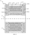
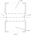
FIG. 9 ,FIG. 10 , andFIG. 11 ,FIG. 9 is a partial schematic diagram of a display equipment of a second embodiment,FIG. 10 is schematic diagram showing the display equipment in a collapsed state of the second embodiment, andFIG. 11 is schematic diagram showing the display equipment in an extended state of the second embodiment. - In this embodiment, the display equipment includes a
first display device 11, asecond display device 12, and a connectingsection 13. The connectingsection 13 includes a central axis. Thefirst display device 11 and thesecond display device 12 are symmetrical about the central axis. - The
first display device 11 has the same structure as thedisplay device 10 in the first embodiment. - Referring to
FIG. 12 andFIG. 13 ,FIG. 12 is schematic diagram of a connecting section of the second embodiment andFIG. 13 is cross-sectional view of the connecting section of the second embodiment. The connectingsection 13 includes ashaft 131, a first connecting piece 132, and a second connectingpiece 133. An axis of theshaft 131 coincides with the central axis of the connectingsection 13. - The first connecting piece 132 includes a
first connection body 1321 and a first connectingbracket 1322. A shape of thefirst connection body 1321 is a hollow cylinder. An inner diameter of thefirst connection body 1321 matches an outer diameter of the shaft 132. Thefirst connection body 1321 is sleeved on the shaft 132. A flat key is also provided between thefirst connection body 1321 and the shaft 132 to axially fix thefirst connection body 1321 and the shaft 132, thereby achieving a function of transmitting torque. - One end of the first connecting
bracket 1322 is connected to an outer wall of thefirst connection body 1321, and the other end of which is connected to one end of thecase 101 of thefirst display device 11. Specifically, the end is connected to a side of thecase 101 parallel to a sliding direction of the slidingchute 1011. - The second connecting
piece 133 includes a second connection body and a second connectingbracket 1332. The second connection body includes afirst connection cavity 13311 and asecond connection cavity 13312. Openings of thefirst connection cavity 13311 and thesecond connection cavity 13312 are oppositely arranged. A distance between thefirst connection cavity 13311 and thesecond connection cavity 13312 is greater than an axial distance of thefirst connection body 1321 on the connectingshaft 131. After theshaft 131 is sleeved within thefirst connection body 1321, axial ends of theshaft 131 are rotatably inserted into thefirst connection cavity 13311 and thesecond connection cavity 13312. A rotation mode of theshaft 131 includes a gear rotation, a belt drive, or motor rotation, which is not limited here. - One end of the second connecting
bracket 1332 is connected to the second connection body 1331, and the other end of which is connected to thesecond display device 12. - There is a second
flexible screen 1301 on one side of the connectingsection 13. One end of the secondflexible screen 1301 is formed integrally with the flexible screen 100 of thefirst display device 11. The other end of the secondflexible screen 1301 is formed integrally with the flexible screen 100 of thesecond display device 12, thereby ensuring a display quality of the display equipment 1. - The description about the embodiments is merely provided to help understand the technical solutions and core ideas of the present disclosure. Those of ordinary skill in the art should understand that they can still modify the technical solutions described in the foregoing embodiments, or equivalently replace some of the technical features. These modifications or replacements do not deviate the essence of the corresponding technical solutions from the scope of the technical solutions of the embodiments of the present disclosure.
Claims (10)
- A display device, comprising:a frame, wherein a width of the frame is adjustable; anda flexible screen installed on the frame, wherein a width of the flexible screen is adjustable.
- The display device as claimed in claim 1, wherein the frame comprises:a case formed with a plurality of sliding chutes parallel to each other, wherein each sliding chute comprises a first chute mouth and a second chute mouth opposite to the first chute mouth;a first bracket comprising a first sliding block, wherein the first sliding block is slidably inserted into at least one sliding chute, and the first sliding block passes through the first chute mouth of the sliding chute; anda second bracket comprising a second sliding block, wherein the second sliding block is slidably inserted into at least one sliding chute, and the second sliding block passes through the second chute mouth of the sliding chute.
- The display device as claimed in claim 2, wherein the first bracket comprises a first box and a first scroll rotatably connected to two opposite inner walls of the first box, wherein a central axis of the first scroll is perpendicular to an extending direction of the sliding chutes; and
wherein the second bracket comprises a second box and a second scroll rotatably connected to two opposite inner walls of the second box, wherein a central axis of the second scroll is parallel to the central axis of the first scroll. - The display device as claimed in claim 3, further comprising:a first motor, wherein a rotor of the first motor is connected to the first scroll; anda second motor, wherein a rotor of the second motor is connected to the second scroll.
- The display device as claimed in claim 1, wherein the flexible screen comprises a central display area, a first extension area, and a second extension area, which are formed integrally;wherein the central display area comprises a first side and a second side opposite to the first side;wherein one end of the first extension area is connected to the first side of the central display area, and another end of the first extension area is spirally sleeved on an outer wall of the first scroll and is connected to the first scroll; andwherein one end of the second extension area is connected to the second side of the central display area, and another end of the second extension area is spirally sleeved on an outer wall of the second scroll and is connected to the second scroll.
- A display equipment, comprising two display devices as claimed in claim 1.
- The display equipment as claimed in claim 6, further comprising:a first display device comprising a first frame and a first flexible screen; anda second display device comprising a second frame and a second flexible screen, wherein the first flexible screen and the second flexible screen are formed integrally.
- The display equipment as claimed in claim 7, further comprising a connecting section, wherein two ends of the connecting section are rotatably connected to the first frame and the second frame, respectively.
- The display equipment as claimed in claim 8, wherein the connecting section comprises:a shaft;a first connecting piece, wherein one end of the first connecting piece is rotatably connected to the shaft, and another end of the first connecting piece is fixedly connected to the first frame; anda second connecting piece, wherein one end of the second connecting piece is rotatably connected to the shaft, and another end of the second connecting piece is fixedly connected to the second frame.
- The display equipment as claimed in claim 7, further comprising a third flexible screen disposed on a surface of the connecting section, wherein the third flexible screen is formed integrally with the first flexible screen and the second flexible screen.
Applications Claiming Priority (2)
| Application Number | Priority Date | Filing Date | Title |
|---|---|---|---|
| CN202010220511.XA CN111402731B (en) | 2020-03-25 | 2020-03-25 | Display device and display apparatus |
| PCT/CN2020/084088 WO2021189543A1 (en) | 2020-03-25 | 2020-04-10 | Display apparatus and display device |
Publications (3)
| Publication Number | Publication Date |
|---|---|
| EP4131218A1 true EP4131218A1 (en) | 2023-02-08 |
| EP4131218A4 EP4131218A4 (en) | 2024-04-24 |
| EP4131218B1 EP4131218B1 (en) | 2025-01-01 |
Family
ID=77857619
Family Applications (1)
| Application Number | Title | Priority Date | Filing Date |
|---|---|---|---|
| EP20750155.2A Active EP4131218B1 (en) | 2020-03-25 | 2020-04-10 | Display device and display equipment |
Country Status (2)
| Country | Link |
|---|---|
| US (1) | US11259427B2 (en) |
| EP (1) | EP4131218B1 (en) |
Families Citing this family (4)
| Publication number | Priority date | Publication date | Assignee | Title |
|---|---|---|---|---|
| US11423810B2 (en) * | 2020-05-15 | 2022-08-23 | Wuhan China Star Optoelectronics Semiconductor Display Technology Co., Ltd. | Flexible display device |
| CN113496656B (en) * | 2021-07-28 | 2022-05-31 | 武汉华星光电技术有限公司 | Curling flexible display device and terminal equipment |
| CN117460186A (en) * | 2022-07-18 | 2024-01-26 | 维沃移动通信有限公司 | Electronic equipment |
| CN115359718B (en) * | 2022-07-18 | 2024-06-28 | 西安中诺通讯有限公司 | Scroll structure, scroll screen terminal and screen display area switching method |
Family Cites Families (17)
| Publication number | Priority date | Publication date | Assignee | Title |
|---|---|---|---|---|
| US9164538B2 (en) * | 2002-06-13 | 2015-10-20 | Jerry Moscovitch | Graphics and monitor controller assemblies in multi-screen display systems |
| US7830333B2 (en) * | 2006-12-13 | 2010-11-09 | Palo Alto Research Center Incorporated | Slide-out information display |
| WO2009089105A1 (en) | 2008-01-04 | 2009-07-16 | Nanolumens | Flexible display |
| US9330589B2 (en) | 2011-11-16 | 2016-05-03 | Nanolumens Acquisition, Inc. | Systems for facilitating virtual presence |
| US8379377B2 (en) * | 2010-01-20 | 2013-02-19 | Creator Technology B.V. | Electronic device with at least one extendable display section |
| CN103839493A (en) | 2014-01-07 | 2014-06-04 | 罗盛 | Soft and hard combined large outdoor LED display screen and manufacturing method thereof |
| CN104075276B (en) | 2014-07-03 | 2017-03-08 | 深圳市华星光电技术有限公司 | The backboard of curvature-adjustable section and the liquid crystal indicator with this backboard |
| US9280010B2 (en) | 2014-07-03 | 2016-03-08 | Shenzhen China Star Optoelectronics Technology Co., Ltd | Curvature-adjustable backplane and liquid crystal display device having same |
| CN104851366B (en) | 2015-05-29 | 2018-02-06 | 京东方科技集团股份有限公司 | A kind of flexible display apparatus |
| CN106847103B (en) * | 2016-12-28 | 2019-05-31 | 上海天马微电子有限公司 | Flexible display device |
| KR102471116B1 (en) * | 2016-05-12 | 2022-11-28 | 삼성디스플레이 주식회사 | Rollable display |
| CN106157816B (en) | 2016-07-08 | 2017-11-17 | 广东欧珀移动通信有限公司 | A kind of flexible display apparatus |
| KR102631840B1 (en) * | 2016-10-06 | 2024-01-31 | 삼성디스플레이 주식회사 | Expandable display device |
| KR102627801B1 (en) * | 2016-10-10 | 2024-01-22 | 삼성디스플레이 주식회사 | Expandable display device |
| CN107331303B (en) | 2017-08-17 | 2019-10-25 | 深圳市华星光电技术有限公司 | Curved-surface display device and its curvature regulating mechanism |
| TWM582287U (en) * | 2019-05-16 | 2019-08-11 | 和碩聯合科技股份有限公司 | Protection case |
| CN110706600B (en) * | 2019-10-29 | 2021-12-03 | 武汉华星光电半导体显示技术有限公司 | Flexible display device |
-
2020
- 2020-04-10 US US16/957,769 patent/US11259427B2/en active Active
- 2020-04-10 EP EP20750155.2A patent/EP4131218B1/en active Active
Also Published As
| Publication number | Publication date |
|---|---|
| EP4131218A4 (en) | 2024-04-24 |
| EP4131218B1 (en) | 2025-01-01 |
| US20210307182A1 (en) | 2021-09-30 |
| US11259427B2 (en) | 2022-02-22 |
Similar Documents
| Publication | Publication Date | Title |
|---|---|---|
| US11259427B2 (en) | Display device and display equipment | |
| CN110166591A (en) | Folding device, flexible display and mobile terminal | |
| CN1493950A (en) | Input device with rollable display and foldable keyboard and personal computer equipped with same | |
| US20160047156A1 (en) | Transmission device applied to pivot shaft mechanism | |
| WO2021189543A1 (en) | Display apparatus and display device | |
| WO2021218368A1 (en) | Electronic assembly and electronic device | |
| WO2016123871A1 (en) | Hinge providing cushioning effect and apparatus provided with the hinge | |
| CN218671330U (en) | Curved surface adjusting device and LED display screen | |
| CN116074415A (en) | Folding mechanism and foldable electronic device | |
| CN103813678A (en) | Locking device | |
| EP4210178A1 (en) | Power adapter and electronic device assembly | |
| CN211669892U (en) | Information display device in transportation equipment | |
| CN113596224A (en) | Electronic device | |
| CN205876951U (en) | Synchronous transmission structure with double rotating shafts | |
| CN217902667U (en) | Propaganda device | |
| CN218569384U (en) | Data transmission device | |
| CN110535374A (en) | An auxiliary placement device for a magnetic levitation system | |
| TWI525895B (en) | Pull out structure and device of rod | |
| CN215521597U (en) | Rotating shaft structure of notebook computer | |
| CN209692745U (en) | Angle Adjustable Industrial Portable Machine | |
| CN115988377A (en) | Charging box and earphone equipment | |
| KR20230107813A (en) | Charging device, electronic device assembly | |
| CN203867291U (en) | Sliding door lock | |
| CN116412199A (en) | Hinge mechanism and mobile terminal | |
| WO2022001306A1 (en) | Folding apparatus and electronic device |
Legal Events
| Date | Code | Title | Description |
|---|---|---|---|
| STAA | Information on the status of an ep patent application or granted ep patent |
Free format text: STATUS: UNKNOWN |
|
| STAA | Information on the status of an ep patent application or granted ep patent |
Free format text: STATUS: THE INTERNATIONAL PUBLICATION HAS BEEN MADE |
|
| PUAI | Public reference made under article 153(3) epc to a published international application that has entered the european phase |
Free format text: ORIGINAL CODE: 0009012 |
|
| STAA | Information on the status of an ep patent application or granted ep patent |
Free format text: STATUS: REQUEST FOR EXAMINATION WAS MADE |
|
| 17P | Request for examination filed |
Effective date: 20200811 |
|
| AK | Designated contracting states |
Kind code of ref document: A1 Designated state(s): AL AT BE BG CH CY CZ DE DK EE ES FI FR GB GR HR HU IE IS IT LI LT LU LV MC MK MT NL NO PL PT RO RS SE SI SK SM TR |
|
| DAV | Request for validation of the european patent (deleted) | ||
| DAX | Request for extension of the european patent (deleted) | ||
| A4 | Supplementary search report drawn up and despatched |
Effective date: 20240325 |
|
| RIC1 | Information provided on ipc code assigned before grant |
Ipc: H05K 7/14 20060101ALI20240319BHEP Ipc: H05K 5/00 20060101ALI20240319BHEP Ipc: G09F 9/30 20060101AFI20240319BHEP |
|
| GRAP | Despatch of communication of intention to grant a patent |
Free format text: ORIGINAL CODE: EPIDOSNIGR1 |
|
| STAA | Information on the status of an ep patent application or granted ep patent |
Free format text: STATUS: GRANT OF PATENT IS INTENDED |
|
| INTG | Intention to grant announced |
Effective date: 20241009 |
|
| GRAS | Grant fee paid |
Free format text: ORIGINAL CODE: EPIDOSNIGR3 |
|
| GRAA | (expected) grant |
Free format text: ORIGINAL CODE: 0009210 |
|
| STAA | Information on the status of an ep patent application or granted ep patent |
Free format text: STATUS: THE PATENT HAS BEEN GRANTED |
|
| P01 | Opt-out of the competence of the unified patent court (upc) registered |
Free format text: CASE NUMBER: APP_58066/2024 Effective date: 20241024 |
|
| AK | Designated contracting states |
Kind code of ref document: B1 Designated state(s): AL AT BE BG CH CY CZ DE DK EE ES FI FR GB GR HR HU IE IS IT LI LT LU LV MC MK MT NL NO PL PT RO RS SE SI SK SM TR |
|
| REG | Reference to a national code |
Ref country code: GB Ref legal event code: FG4D |
|
| REG | Reference to a national code |
Ref country code: CH Ref legal event code: EP |
|
| REG | Reference to a national code |
Ref country code: DE Ref legal event code: R096 Ref document number: 602020044063 Country of ref document: DE |
|
| REG | Reference to a national code |
Ref country code: IE Ref legal event code: FG4D |
|
| REG | Reference to a national code |
Ref country code: LT Ref legal event code: MG9D |
|
| REG | Reference to a national code |
Ref country code: NL Ref legal event code: MP Effective date: 20250101 |
|
| REG | Reference to a national code |
Ref country code: AT Ref legal event code: MK05 Ref document number: 1757120 Country of ref document: AT Kind code of ref document: T Effective date: 20250101 |
|
| PG25 | Lapsed in a contracting state [announced via postgrant information from national office to epo] |
Ref country code: NL Free format text: LAPSE BECAUSE OF FAILURE TO SUBMIT A TRANSLATION OF THE DESCRIPTION OR TO PAY THE FEE WITHIN THE PRESCRIBED TIME-LIMIT Effective date: 20250101 |
|
| PG25 | Lapsed in a contracting state [announced via postgrant information from national office to epo] |
Ref country code: FI Free format text: LAPSE BECAUSE OF FAILURE TO SUBMIT A TRANSLATION OF THE DESCRIPTION OR TO PAY THE FEE WITHIN THE PRESCRIBED TIME-LIMIT Effective date: 20250101 |
|
| PG25 | Lapsed in a contracting state [announced via postgrant information from national office to epo] |
Ref country code: PL Free format text: LAPSE BECAUSE OF FAILURE TO SUBMIT A TRANSLATION OF THE DESCRIPTION OR TO PAY THE FEE WITHIN THE PRESCRIBED TIME-LIMIT Effective date: 20250101 |
|
| PGFP | Annual fee paid to national office [announced via postgrant information from national office to epo] |
Ref country code: DE Payment date: 20250422 Year of fee payment: 6 |
|
| PG25 | Lapsed in a contracting state [announced via postgrant information from national office to epo] |
Ref country code: ES Free format text: LAPSE BECAUSE OF FAILURE TO SUBMIT A TRANSLATION OF THE DESCRIPTION OR TO PAY THE FEE WITHIN THE PRESCRIBED TIME-LIMIT Effective date: 20250101 |
|
| PG25 | Lapsed in a contracting state [announced via postgrant information from national office to epo] |
Ref country code: IS Free format text: LAPSE BECAUSE OF FAILURE TO SUBMIT A TRANSLATION OF THE DESCRIPTION OR TO PAY THE FEE WITHIN THE PRESCRIBED TIME-LIMIT Effective date: 20250501 Ref country code: NO Free format text: LAPSE BECAUSE OF FAILURE TO SUBMIT A TRANSLATION OF THE DESCRIPTION OR TO PAY THE FEE WITHIN THE PRESCRIBED TIME-LIMIT Effective date: 20250401 |
|
| PG25 | Lapsed in a contracting state [announced via postgrant information from national office to epo] |
Ref country code: HR Free format text: LAPSE BECAUSE OF FAILURE TO SUBMIT A TRANSLATION OF THE DESCRIPTION OR TO PAY THE FEE WITHIN THE PRESCRIBED TIME-LIMIT Effective date: 20250101 |
|
| PG25 | Lapsed in a contracting state [announced via postgrant information from national office to epo] |
Ref country code: LV Free format text: LAPSE BECAUSE OF FAILURE TO SUBMIT A TRANSLATION OF THE DESCRIPTION OR TO PAY THE FEE WITHIN THE PRESCRIBED TIME-LIMIT Effective date: 20250101 Ref country code: PT Free format text: LAPSE BECAUSE OF FAILURE TO SUBMIT A TRANSLATION OF THE DESCRIPTION OR TO PAY THE FEE WITHIN THE PRESCRIBED TIME-LIMIT Effective date: 20250502 |
|
| PG25 | Lapsed in a contracting state [announced via postgrant information from national office to epo] |
Ref country code: GR Free format text: LAPSE BECAUSE OF FAILURE TO SUBMIT A TRANSLATION OF THE DESCRIPTION OR TO PAY THE FEE WITHIN THE PRESCRIBED TIME-LIMIT Effective date: 20250402 Ref country code: BG Free format text: LAPSE BECAUSE OF FAILURE TO SUBMIT A TRANSLATION OF THE DESCRIPTION OR TO PAY THE FEE WITHIN THE PRESCRIBED TIME-LIMIT Effective date: 20250101 |
|
| PG25 | Lapsed in a contracting state [announced via postgrant information from national office to epo] |
Ref country code: AT Free format text: LAPSE BECAUSE OF FAILURE TO SUBMIT A TRANSLATION OF THE DESCRIPTION OR TO PAY THE FEE WITHIN THE PRESCRIBED TIME-LIMIT Effective date: 20250101 |
|
| PG25 | Lapsed in a contracting state [announced via postgrant information from national office to epo] |
Ref country code: CZ Free format text: LAPSE BECAUSE OF FAILURE TO SUBMIT A TRANSLATION OF THE DESCRIPTION OR TO PAY THE FEE WITHIN THE PRESCRIBED TIME-LIMIT Effective date: 20250101 |
|
| PG25 | Lapsed in a contracting state [announced via postgrant information from national office to epo] |
Ref country code: SE Free format text: LAPSE BECAUSE OF FAILURE TO SUBMIT A TRANSLATION OF THE DESCRIPTION OR TO PAY THE FEE WITHIN THE PRESCRIBED TIME-LIMIT Effective date: 20250101 |
|
| REG | Reference to a national code |
Ref country code: DE Ref legal event code: R097 Ref document number: 602020044063 Country of ref document: DE |
|
| PG25 | Lapsed in a contracting state [announced via postgrant information from national office to epo] |
Ref country code: SM Free format text: LAPSE BECAUSE OF FAILURE TO SUBMIT A TRANSLATION OF THE DESCRIPTION OR TO PAY THE FEE WITHIN THE PRESCRIBED TIME-LIMIT Effective date: 20250101 |
|
| PG25 | Lapsed in a contracting state [announced via postgrant information from national office to epo] |
Ref country code: DK Free format text: LAPSE BECAUSE OF FAILURE TO SUBMIT A TRANSLATION OF THE DESCRIPTION OR TO PAY THE FEE WITHIN THE PRESCRIBED TIME-LIMIT Effective date: 20250101 |
|
| PG25 | Lapsed in a contracting state [announced via postgrant information from national office to epo] |
Ref country code: IT Free format text: LAPSE BECAUSE OF FAILURE TO SUBMIT A TRANSLATION OF THE DESCRIPTION OR TO PAY THE FEE WITHIN THE PRESCRIBED TIME-LIMIT Effective date: 20250101 |
|
| PG25 | Lapsed in a contracting state [announced via postgrant information from national office to epo] |
Ref country code: EE Free format text: LAPSE BECAUSE OF FAILURE TO SUBMIT A TRANSLATION OF THE DESCRIPTION OR TO PAY THE FEE WITHIN THE PRESCRIBED TIME-LIMIT Effective date: 20250101 |
|
| PG25 | Lapsed in a contracting state [announced via postgrant information from national office to epo] |
Ref country code: RO Free format text: LAPSE BECAUSE OF FAILURE TO SUBMIT A TRANSLATION OF THE DESCRIPTION OR TO PAY THE FEE WITHIN THE PRESCRIBED TIME-LIMIT Effective date: 20250101 |
|
| PG25 | Lapsed in a contracting state [announced via postgrant information from national office to epo] |
Ref country code: SK Free format text: LAPSE BECAUSE OF FAILURE TO SUBMIT A TRANSLATION OF THE DESCRIPTION OR TO PAY THE FEE WITHIN THE PRESCRIBED TIME-LIMIT Effective date: 20250101 |
|
| PLBE | No opposition filed within time limit |
Free format text: ORIGINAL CODE: 0009261 |
|
| STAA | Information on the status of an ep patent application or granted ep patent |
Free format text: STATUS: NO OPPOSITION FILED WITHIN TIME LIMIT |
|
| REG | Reference to a national code |
Ref country code: CH Ref legal event code: L10 Free format text: ST27 STATUS EVENT CODE: U-0-0-L10-L00 (AS PROVIDED BY THE NATIONAL OFFICE) Effective date: 20251112 |
|
| REG | Reference to a national code |
Ref country code: CH Ref legal event code: H13 Free format text: ST27 STATUS EVENT CODE: U-0-0-H10-H13 (AS PROVIDED BY THE NATIONAL OFFICE) Effective date: 20251125 |
|
| 26N | No opposition filed |
Effective date: 20251002 |
|
| PG25 | Lapsed in a contracting state [announced via postgrant information from national office to epo] |
Ref country code: LU Free format text: LAPSE BECAUSE OF NON-PAYMENT OF DUE FEES Effective date: 20250410 |
|
| PG25 | Lapsed in a contracting state [announced via postgrant information from national office to epo] |
Ref country code: MC Free format text: LAPSE BECAUSE OF FAILURE TO SUBMIT A TRANSLATION OF THE DESCRIPTION OR TO PAY THE FEE WITHIN THE PRESCRIBED TIME-LIMIT Effective date: 20250101 |
|
| GBPC | Gb: european patent ceased through non-payment of renewal fee |
Effective date: 20250410 |
|
| REG | Reference to a national code |
Ref country code: BE Ref legal event code: MM Effective date: 20250430 |
|
| PG25 | Lapsed in a contracting state [announced via postgrant information from national office to epo] |
Ref country code: GB Free format text: LAPSE BECAUSE OF NON-PAYMENT OF DUE FEES Effective date: 20250410 |
|
| PG25 | Lapsed in a contracting state [announced via postgrant information from national office to epo] |
Ref country code: FR Free format text: LAPSE BECAUSE OF NON-PAYMENT OF DUE FEES Effective date: 20250430 |
|
| PG25 | Lapsed in a contracting state [announced via postgrant information from national office to epo] |
Ref country code: BE Free format text: LAPSE BECAUSE OF NON-PAYMENT OF DUE FEES Effective date: 20250430 |
|
| PG25 | Lapsed in a contracting state [announced via postgrant information from national office to epo] |
Ref country code: CH Free format text: LAPSE BECAUSE OF NON-PAYMENT OF DUE FEES Effective date: 20250430 |
|
| PG25 | Lapsed in a contracting state [announced via postgrant information from national office to epo] |
Ref country code: IE Free format text: LAPSE BECAUSE OF NON-PAYMENT OF DUE FEES Effective date: 20250410 |