EP4131215A1 - Movement assistance device and movement assistance method - Google Patents
Movement assistance device and movement assistance method Download PDFInfo
- Publication number
- EP4131215A1 EP4131215A1 EP21777926.3A EP21777926A EP4131215A1 EP 4131215 A1 EP4131215 A1 EP 4131215A1 EP 21777926 A EP21777926 A EP 21777926A EP 4131215 A1 EP4131215 A1 EP 4131215A1
- Authority
- EP
- European Patent Office
- Prior art keywords
- user
- route
- required time
- time
- routes
- Prior art date
- Legal status (The legal status is an assumption and is not a legal conclusion. Google has not performed a legal analysis and makes no representation as to the accuracy of the status listed.)
- Granted
Links
Images


Classifications
-
- G—PHYSICS
- G01—MEASURING; TESTING
- G01C—MEASURING DISTANCES, LEVELS OR BEARINGS; SURVEYING; NAVIGATION; GYROSCOPIC INSTRUMENTS; PHOTOGRAMMETRY OR VIDEOGRAMMETRY
- G01C21/00—Navigation; Navigational instruments not provided for in groups G01C1/00 - G01C19/00
- G01C21/26—Navigation; Navigational instruments not provided for in groups G01C1/00 - G01C19/00 specially adapted for navigation in a road network
- G01C21/34—Route searching; Route guidance
- G01C21/3453—Special cost functions, i.e. other than distance or default speed limit of road segments
- G01C21/3461—Preferred or disfavoured areas, e.g. dangerous zones, toll or emission zones, intersections, manoeuvre types or segments such as motorways, toll roads or ferries
-
- G—PHYSICS
- G09—EDUCATION; CRYPTOGRAPHY; DISPLAY; ADVERTISING; SEALS
- G09B—EDUCATIONAL OR DEMONSTRATION APPLIANCES; APPLIANCES FOR TEACHING, OR COMMUNICATING WITH, THE BLIND, DEAF OR MUTE; MODELS; PLANETARIA; GLOBES; MAPS; DIAGRAMS
- G09B29/00—Maps; Plans; Charts; Diagrams, e.g. route diagram
- G09B29/10—Map spot or coordinate position indicators; Map reading aids
- G09B29/106—Map spot or coordinate position indicators; Map reading aids using electronic means
-
- G—PHYSICS
- G01—MEASURING; TESTING
- G01C—MEASURING DISTANCES, LEVELS OR BEARINGS; SURVEYING; NAVIGATION; GYROSCOPIC INSTRUMENTS; PHOTOGRAMMETRY OR VIDEOGRAMMETRY
- G01C21/00—Navigation; Navigational instruments not provided for in groups G01C1/00 - G01C19/00
- G01C21/26—Navigation; Navigational instruments not provided for in groups G01C1/00 - G01C19/00 specially adapted for navigation in a road network
- G01C21/34—Route searching; Route guidance
- G01C21/3407—Route searching; Route guidance specially adapted for specific applications
- G01C21/3423—Multimodal routing
-
- G—PHYSICS
- G01—MEASURING; TESTING
- G01C—MEASURING DISTANCES, LEVELS OR BEARINGS; SURVEYING; NAVIGATION; GYROSCOPIC INSTRUMENTS; PHOTOGRAMMETRY OR VIDEOGRAMMETRY
- G01C21/00—Navigation; Navigational instruments not provided for in groups G01C1/00 - G01C19/00
- G01C21/26—Navigation; Navigational instruments not provided for in groups G01C1/00 - G01C19/00 specially adapted for navigation in a road network
- G01C21/34—Route searching; Route guidance
- G01C21/3407—Route searching; Route guidance specially adapted for specific applications
- G01C21/3438—Rendezvous; Ride sharing
-
- G—PHYSICS
- G01—MEASURING; TESTING
- G01C—MEASURING DISTANCES, LEVELS OR BEARINGS; SURVEYING; NAVIGATION; GYROSCOPIC INSTRUMENTS; PHOTOGRAMMETRY OR VIDEOGRAMMETRY
- G01C21/00—Navigation; Navigational instruments not provided for in groups G01C1/00 - G01C19/00
- G01C21/26—Navigation; Navigational instruments not provided for in groups G01C1/00 - G01C19/00 specially adapted for navigation in a road network
- G01C21/34—Route searching; Route guidance
- G01C21/36—Input/output arrangements for on-board computers
- G01C21/3667—Display of a road map
- G01C21/3676—Overview of the route on the road map
-
- G—PHYSICS
- G01—MEASURING; TESTING
- G01C—MEASURING DISTANCES, LEVELS OR BEARINGS; SURVEYING; NAVIGATION; GYROSCOPIC INSTRUMENTS; PHOTOGRAMMETRY OR VIDEOGRAMMETRY
- G01C21/00—Navigation; Navigational instruments not provided for in groups G01C1/00 - G01C19/00
- G01C21/26—Navigation; Navigational instruments not provided for in groups G01C1/00 - G01C19/00 specially adapted for navigation in a road network
- G01C21/34—Route searching; Route guidance
- G01C21/36—Input/output arrangements for on-board computers
- G01C21/3679—Retrieval, searching and output of POI information, e.g. hotels, restaurants, shops, filling stations, parking facilities
- G01C21/3682—Retrieval, searching and output of POI information, e.g. hotels, restaurants, shops, filling stations, parking facilities output of POI information on a road map
-
- G—PHYSICS
- G06—COMPUTING OR CALCULATING; COUNTING
- G06Q—INFORMATION AND COMMUNICATION TECHNOLOGY [ICT] SPECIALLY ADAPTED FOR ADMINISTRATIVE, COMMERCIAL, FINANCIAL, MANAGERIAL OR SUPERVISORY PURPOSES; SYSTEMS OR METHODS SPECIALLY ADAPTED FOR ADMINISTRATIVE, COMMERCIAL, FINANCIAL, MANAGERIAL OR SUPERVISORY PURPOSES, NOT OTHERWISE PROVIDED FOR
- G06Q10/00—Administration; Management
- G06Q10/02—Reservations, e.g. for tickets, services or events
-
- G—PHYSICS
- G06—COMPUTING OR CALCULATING; COUNTING
- G06Q—INFORMATION AND COMMUNICATION TECHNOLOGY [ICT] SPECIALLY ADAPTED FOR ADMINISTRATIVE, COMMERCIAL, FINANCIAL, MANAGERIAL OR SUPERVISORY PURPOSES; SYSTEMS OR METHODS SPECIALLY ADAPTED FOR ADMINISTRATIVE, COMMERCIAL, FINANCIAL, MANAGERIAL OR SUPERVISORY PURPOSES, NOT OTHERWISE PROVIDED FOR
- G06Q10/00—Administration; Management
- G06Q10/04—Forecasting or optimisation specially adapted for administrative or management purposes, e.g. linear programming or "cutting stock problem"
- G06Q10/047—Optimisation of routes or paths, e.g. travelling salesman problem
-
- G—PHYSICS
- G06—COMPUTING OR CALCULATING; COUNTING
- G06Q—INFORMATION AND COMMUNICATION TECHNOLOGY [ICT] SPECIALLY ADAPTED FOR ADMINISTRATIVE, COMMERCIAL, FINANCIAL, MANAGERIAL OR SUPERVISORY PURPOSES; SYSTEMS OR METHODS SPECIALLY ADAPTED FOR ADMINISTRATIVE, COMMERCIAL, FINANCIAL, MANAGERIAL OR SUPERVISORY PURPOSES, NOT OTHERWISE PROVIDED FOR
- G06Q10/00—Administration; Management
- G06Q10/06—Resources, workflows, human or project management; Enterprise or organisation planning; Enterprise or organisation modelling
- G06Q10/063—Operations research, analysis or management
-
- G—PHYSICS
- G08—SIGNALLING
- G08G—TRAFFIC CONTROL SYSTEMS
- G08G1/00—Traffic control systems for road vehicles
- G08G1/005—Traffic control systems for road vehicles including pedestrian guidance indicator
-
- G—PHYSICS
- G08—SIGNALLING
- G08G—TRAFFIC CONTROL SYSTEMS
- G08G1/00—Traffic control systems for road vehicles
- G08G1/20—Monitoring the location of vehicles belonging to a group, e.g. fleet of vehicles, countable or determined number of vehicles
- G08G1/202—Dispatching vehicles on the basis of a location, e.g. taxi dispatching
Definitions
- the present invention relates to a movement assistance device and a movement assistance method.
- Patent Document 1 A technology for guiding a user to a meeting location where the user is to meet a vehicle is known from the prior art (Patent Document 1).
- Patent Document 1 Japanese Laid-Open Patent Application No. 2013-130544
- Patent Document 1 only presents the user with one route. The user cannot select a route other than the presented route, and thus has few options regarding movement.
- an object of the present invention is to provide a movement assistance device and a movement assistance method that present at least one route to a meeting location.
- a movement assistance device that acquires location information of a communication device in the possession of a user and location information of a vehicle dispatched in accordance with the user's dispatch request calculates, based on the location information of the vehicle, a first required time, which is the time required for the vehicle to arrive at a meeting location where the user who made the dispatch request is to board the vehicle; calculates, based on the location information of the communication device, a plurality of routes from a current location of the user to the meeting location; calculates a second required time, which is the time required to arrive at the meeting location from the current location of the user, for each of the plurality of calculated routes; determines that if the second required times are the same as or shorter than the first required time, the routes associated with the second required times are routes via which the vehicle could be met on time; and causes the communication device to output information that indicates the route or routes determined to be the route or routes via which the vehicle could be met on time.
- the movement assistance system 10 includes a management server 20, a communication network 30, taxis 40 to 42, a user 70, and a communication device 60 in the possession of the user 70.
- the movement assistance system 10 may include four or more taxis.
- the management server 20 communicates with the taxis 40 to 42 and the communication device 60 via the communication network 30.
- the management server 20 is a general-purpose computer equipped with a CPU (Central Processing Unit) 21, a memory 22, a communication I/F 23, and a storage device 24; these constituent elements are electrically connected via a bus, etc., not shown in the figure.
- the management server 20 is used in a dispatch service for the taxis 40 to 42.
- the installation location of the management server 20 is not particularly limited, the management server 20 is installed, for example, in the control center of the business that operates the taxis 40 to 42.
- the CPU 21 reads various programs stored in the storage device 24, etc., into the memory 22 and executes various instructions contained in the programs.
- the memory 22 is a storage medium such as a ROM (Read Only Memory), RAM (Random Access Memory), etc.
- the storage device 24 is a storage medium such as an HDD (Hard Disk Drive).
- the communication I/F 23 is implemented as hardware, such as a network adapter, various types of communication software, or a combination thereof, and is configured to realize wired or wireless communication via the communication network 30, etc. Further, the communication I/F 23 functions as an input/output unit for sending and receiving data.
- the communication network 30 may be configured by a wireless and/or wired method, and the communication network 30 may include the Internet.
- the management server 20, the taxis 40 to 42, and the communication device 60 are connected to the communication network 30 by using a wireless communication method.
- the taxis 40 to 42 are described as autonomous driving vehicles without a driver. Therefore, the taxis 40 to 42 may be described as robot taxis or unmanned taxis. However, the taxis 40 to 42 are not limited to autonomous driving vehicles without drivers. The taxis 40 to 42 may be ordinary vehicles with drivers.
- the user 70 requests (reserves) a taxi using the communication device 60.
- a vehicle dispatch application (hereinafter referred to simply as a vehicle dispatch app) used for reserving taxis is installed in the communication device 60, and the user 70 requests a taxi using the vehicle dispatch app.
- the communication device 60 comprises a communication I/F 601, a vehicle dispatch app 602, a GPS receiver 603, and a display 604.
- the communication I/F 601 has the same configuration as the communication I/F 23 (refer to Figure 1 ) and communicates with the management server 20 via the communication network 30.
- the communication device 60 is a portable device such as a smartphone or a tablet.
- the communication device 60 may also be a wearable device.
- the communication device 60 comprises a CPU (controller), memory, storage device, etc., in the same manner as the management server 20.
- the vehicle dispatch app 602 is used for requesting a taxi, as described above.
- the vehicle dispatch app 602 functions as a user interface when the user 70 requests a taxi.
- the vehicle dispatch app 602 is realized by the CPU provided in the communication device 60 reading and executing a dedicated application program from a storage device provided in the communication device 60.
- the user 70 inputs a desired boarding location, boarding time, deboarding location, etc., into the vehicle dispatch app 602 to request a taxi.
- the vehicle dispatch app 602 transmits a dispatch request to the management server 20 in accordance with the input from the user 70.
- the communication device 60 displays on the display 604 various types of information (dispatch request receipt, scheduled arrival time, scheduled travel route, etc.) included in the signal returned from the management server 20 in response to the dispatch request.
- the method of realizing the vehicle dispatch app 602 is not limited in this way.
- the communication device 60 may access a server that provides the functions of the vehicle dispatch app 602, receive the functions provided, and display the results of executing the functions transmitted from the server in a browser.
- the location information of the communication device 60 acquired by the GPS receiver 603 is transmitted to the management server 20 at any given time.
- the taxi 40 is equipped with a communication I/F 401, a vehicle ECU (Electronic Control Unit) 402, and a GPS receiver 403.
- the communication I/F 401 has the same configuration as the communication I/F 23 and the communication I/F 601, and communicates with the management server 20 via the communication network 30.
- the vehicle ECU 402 is a computer for controlling the taxi 40.
- the vehicle ECU 402 controls various actuators (brake actuator, accelerator pedal actuator, steering actuator, etc.) based on the commands received from the management server 20.
- the location information of the taxi 40 acquired by the GPS receiver 403 is transmitted to the management server 20 at any given time.
- the CPU 21 (the controller) of the management server 20 is provided with, as examples of the plurality of functions, a vehicle dispatch acceptance unit 211, an assignment unit 212, a location information acquisition unit 213, a required time calculation unit 214, a walking route calculation unit 215, a determination unit 216, and a walking route setting unit 217.
- a map database 241 and a client database 242 are stored in the storage device 24 of the management server 20.
- the map information required for route guidance is stored in the map database 241.
- the map information includes the number of lanes on a road, road width information, and road undulation information.
- the map information also includes road signs indicating the speed limit, one-way streets, etc., as well as road markings indicating pedestrian crossings, lane markings, etc.
- the map information may also include information related to road structures (for example, traffic signals and telephone poles), buildings, and other facilities.
- the client database 242 stores account information, such as the ID of the user 70, taxi usage history, and attributes of the user 70.
- the dispatch acceptance unit 211 accepts a dispatch request from the user 70 entered into the communication device 60.
- the dispatch acceptance unit 211 has the function of notifying the communication device 60 of the acceptance of the dispatch request from the user 70, as well as of the scheduled arrival time to the boarding location, the scheduled travel route to the boarding location, etc.
- the assignment unit 212 assigns a suitable taxi from among the plurality of taxis 40 to 42 (refer to Figure 1 ) based on the accepted dispatch request. For example, for reasons of efficiency, the dispatch acceptance unit 211 can assign the unoccupied taxi that, of the plurality of taxis 40 to 42, is closest to the boarding location desired by the user 70. In the present embodiment, it is assumed that the taxi 40 has been assigned.
- the assignment unit 212 also sets a travel route from the current location of the taxi 40 to the boarding location desired by the user 70 by referencing the map database 241 and sends an instruction to the taxi 40 to travel to the boarding location desired by the user 70 via the set travel route.
- the travel route calculated by the assignment unit 212 is, for example, the route via which the boarding location desired by the user 70 can be reached from the current location of the taxi 40 in the shortest amount of time.
- the assignment unit 212 outputs the set travel route to the required time calculation unit 214.
- the location information acquisition unit 213 acquires the location information of the user 70 from the communication device 60 and acquires location information of the taxi 40 from the taxi 40.
- the location information of the user 70 means the location information of the communication device 60 in the possession of the user 70.
- the location information acquisition unit 213 outputs the acquired location information to the required time calculation unit 214.
- the required time calculation unit 214 uses the travel route acquired from the assignment unit 212 and the location information of the taxi 40 acquired from the location information acquisition unit 213 to calculate a first required time or time required for the taxi 40 to arrive at the boarding location desired by the user 70 from its current location
- the required time calculation unit 214 outputs this calculated first required time to the determination unit 216.
- the walking route calculation unit 215 uses the map database 241 and the location information of the user 70 acquired from the location information acquisition unit 213 to calculate walking routes.
- a walking route is a route that the user 70 can take on foot from the current location of the user 70 to the boarding location.
- the walking route calculation unit 215 calculates a plurality of walking routes to the boarding location.
- the required time calculation unit 214 also calculates a second required time, which is the time required for the user 70 to arrive at the boarding location from his or her current location, for each of the plurality of walking routes calculated by the walking route calculation unit 215.
- the required time calculation unit 214 outputs these calculated second required times to the determination unit 216. Each second required time is associated with the corresponding walking route.
- the determination unit 216 determines whether the user 70 can be on time to meet the taxi 40 using the first required time and the second required times obtained from the required time calculation unit 214. For example, if a second required time is shorter than the first required time, the determination unit 216 determines that the user 70 can be on time to meet the taxi 40. Further, if a second required time and the first required time are the same, the determination unit 216 determines that the user 70 can be on time to meet the taxi 40.
- “a second required time and the first required time are the same” does not imply an exact equivalence.
- a second required time and the first required time are the same means that the times are essentially the same (i.e., approximately the same) and that a difference of several seconds is negligible.
- the user 70 can be on time to meet the taxi 40 means that the user 70 can arrive at the boarding location ahead of the taxi 40.
- the user 70 can be on time to meet the taxi 40 can mean that the user 70 and the taxi 40 may arrive at the boarding location at the same time (or approximately the same time).
- the determination unit 216 If it is determined that the user 70 can be on time to meet the taxi 40, the determination unit 216 outputs the walking routes associated with the second required times used to arrive at this determination to the walking route setting unit 217.
- the walking route setting unit 217 sets the walking routes acquired from the determination unit 216 as the walking routes to be presented to the user 70 and transmits a signal indicating the set walking routes to the communication device 60 in the possession of the user 70 via the communication I/F 23.
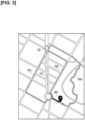
- Reference numeral 80 in Figure 3 indicates the boarding location desired by the user 70. That is, reference numeral 80 indicates the location where the user 70 is to meet the taxi 40. Reference numeral 80 is hereafter designated as meeting location 80.
- the taxi 40 travels to the meeting location 80 in order to board the user 70 based on a command received from the management server 20.
- the taxi 40 is omitted in Figure 3 .
- the required time calculation unit 214 uses the travel route acquired from the assignment unit 212 and the location information of the taxi 40 acquired from the location information acquisition unit 213 to calculate a first required time, which is the time required for the taxi 40 to arrive at the meeting location 80 from its current location. In the following description, it is assumed that the first required time has been calculated as 8 minutes.
- the walking route calculation unit 215 uses the map database 241 and the location information of the user 70 acquired from the location information acquisition unit 213 to calculate walking routes R1 to R4.
- Walking routes R1 to R4 are routes that the user 70 can take on foot from the current location of the user 70 to the meeting location 80.
- the required time calculation unit 214 calculates a second required time, which is the time required to arrive at the meeting location 80 from the current location of the user 70, for each of the walking routes R1 to R4 calculated by the walking route calculation unit 215. It is assumed only in Figure 3 that the second required times for traversing the walking routes are calculated as 5 minutes for the walking route R1, 6 minutes for the walking route R2, 7 minutes for the walking route R3, and 9 minutes for the walking route R4.
- the determination unit 216 determines whether the user 70 can be on time to meet the taxi 40 using the first required time (8 minutes) and the second required times (R1: 5 minutes, R2: 6 minutes, R3: 7 minutes, R4: 9 minutes) acquired from the required time calculation unit 214. Since the taxi 40 will arrive at the meeting location 80 in 8 minutes, if the user 70 can arrive at the meeting location 80 within 8 minutes, the user can meet the taxi 40 on time.
- the determination unit 216 determines whether there is a walking route via which the meeting location 80 can be reached within the first required time. For example, the determination unit 216 compares the first required time and a second required time, and if this second required time is shorter than the first required time, determines that the walking route associated with this second required time is a walking route via which the meeting location 80 can be reached within the first required time.
- the determination unit 216 determines that the walking routes R1 to R3 are the walking routes via which the meeting location 80 can be reached within the first required time. Since the second required time (9 minutes) associated with the walking route R4 is longer than the first required time (8 minutes), on the other hand, the determination unit 216 determines that the walking route R4 cannot be used to arrive at the meeting location 80 within the first required time.
- the determination unit 216 outputs the walking routes R1 to R3 (the walking routes via which the user 70 can meet the taxi 40 on time) to the walking route setting unit 217. Walking route R4, on the other hand, is deleted since it cannot be used to arrive at the meeting location 80 within the first required time.
- the walking route setting unit 217 sets the walking routes R1 to R3 acquired from the determination unit 216 as the walking routes to be presented to the user 70 and transmits a signal indicating the set walking routes R1 to R3 to the communication device 60 in the possession of the user 70 via the communication I/F 23.
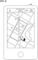
- walking routes R1 to R3 acquired from the management server 20 are displayed on the display 604 of the communication device 60. Regardless of which walking route of the walking routes R1 to R3 the user 70 selects, the user 70 can be on time to meet the taxi 40.
- a plurality of the walking routes R1 to R3 can be presented to the user 70 via which the taxi 40 can be met on time; thus, the user 70 can select his or her preferred route from the plurality of the walking routes R1 to R3. This increases the number of options that the user 70 can choose from when he/she departs for the meeting location 80.
- the user 70 selects his/her preferred route the user is guided along this route to the meeting location 80, as with a well-known navigation system.
- Step S101 the user 70 requests a taxi using the vehicle dispatch app 602.
- the process proceeds to Step S103, in which the dispatch acceptance unit 211 accepts the dispatch request of the user 70.
- the process proceeds to Step S105, in which the assignment unit 212 assigns an appropriate taxi from among the plurality of taxis 40 to 42 (refer to Figure 1 ) based on the accepted dispatch request.
- the process proceeds to Step S107, in which the assignment unit 212 references the map database 241 and sets the travel route from the current location of the taxi 40 to the boarding location desired by the user 70 (meeting location 80).
- Step S109 in which the management server 20 transmits the set travel route to the taxi 40.
- Step S111 in which the taxi 40 travels to the meeting location 80 desired by the user 70 via the acquired travel route.
- Step S113 the communication device 60 transmits the location information of the communication device 60 acquired by the GPS receiver 603 to the management server 20.
- Step S115 the taxi 40 transmits the location information of the taxi 40 acquired by the GPS receiver 403 to the management server 20.
- Step S117 the management server 20 receives the location information transmitted from the communication device 60 and the taxi 40. The process of Step S115 is repeated until the taxi 40 arrives at the meeting location 80 (Step S119).
- Step S121 in which the required time calculation unit 214 calculates the first required time, i.e., the time required for the taxi 40 to arrive at the meeting location 80 from its current location.
- the process proceeds to Step S123, in which the walking route calculation unit 215 calculates the walking routes R1 to R4 (refer to Figure 3 ) using the map database 241 and the location information of the user 70 acquired in Step S117.
- Step S125 the determination unit 216 determines whether any of the walking routes R1 to R4 calculated in Step S123 cannot be used to arrive at the meeting location 80 within the first required time. If there is a walking route R4, as is shown in Figure 3 , via which it is not possible to arrive at the meeting location 80 within the first required time (YES in Step S125), the process proceeds to Step S127, and the walking route R4 is deleted. If, on the other hand, there are the walking routes R1 to R3 via which the meeting location 80 can be reached within the first required time (NO in Step S125), the walking route setting unit 217 sets the walking routes R1 to R3 as the walking routes to be presented to the user 70 (Step S129). The process proceeds to Step S131, in which the walking route setting unit 217 transmits a signal indicating the set walking routes R1 to R3 to the communication device 60 in the possession of the user 70 via the communication I/F 23.
- Step S133 in which the communication device 60 receives a signal indicating the walking routes R1 to R3 transmitted from the management server 20.
- the process proceeds to Step S135, in which walking routes R1 to R3 are displayed on the display 604, as shown in Figure 4 .
- the process of Step S113 is repeated until the user 70 arrives at the meeting location 80 (Step S137).
- the management server 20 is equipped with the location information acquisition unit 213, the first required time calculation unit (the required time calculation unit 214), the route calculation unit (the walking route calculation unit 215), the second required time calculation unit (the required time calculation unit 214), the determination unit 216, and the output unit (the communication I/F 23).
- the location information acquisition unit 213 acquires the location information of the communication device 60 in the possession of the user 70 as well as the location information of the taxi 40 dispatched in accordance with the dispatch request of the user 70.
- the first required time calculation unit calculates, based on the location information of the taxi 40, the first required time or time required for the taxi 40 to arrive at the meeting location 80 where the user 70 who requested the dispatch is to board.
- the route calculation unit calculates, based on the location information of the communication device 60, a plurality of routes from the current location of the user 70 to the meeting location 80.
- the second required time calculation unit calculates a second required time, which is the time required to arrive at the meeting location from the current location of the user, for each of the plurality of routes calculated by the route calculation unit.
- the determination unit 216 determines that the route associated with the second required time is a route via which the taxi 40 could be met on time.
- the output unit causes the communication device 60 to output information indicating the route or routes determined by the determination unit 216 to be thee route or routes via which the taxi 40 could be met on time.
- the user 70 can be presented with the plurality of the walking routes R1 to R3 via which the taxi 40 could be met on time, thereby allowing the user 70 to select a preferred route from the plurality of the walking routes R1 to R3. This increases the number of options that the user 70 can choose from when the user departs for the meeting location 80.
- the management server 20 when the management server 20 transmits a signal indicating the walking routes R1 to R4 to the communication device 60, the management server may also transmit a signal indicating the second required times associated with the walking routes R1 to R4 to the communication device 60.
- the walking routes R1 to R4 acquired from the management server 20 and the second required times associated with the walking routes R1 to R4 are displayed on the display 604 of the communication device 60.
- the second required times for traversing the walking routes have been calculated as 5 minutes for the walking route R1, 6 minutes for the walking route R2, 7 minutes for the walking route R3, and 8 minutes for the walking route R4.
- the walking routes R1 to R3 are walking routes via which the meeting location 80 can be reached within the first required time.
- walking route R4 is also a walking route via which the meeting location 80 can be reached within the first required time. Because the second required time (8 minutes) associated with the walking route R4 is the same as the first required time (8 minutes), the determination unit 216 determines that walking route R4 is a walking route via which the meeting location 80 can be reached within the first required time.
- walking routes R1 to R4 and the second required times associated with the walking routes R1 to R4 are displayed on the display 604, the user 70, when choosing between the walking routes, can ascertain at a glance the associated walking times. The user 70 can select his or her preferred route from the walking routes R1 to R4 in consideration of the walking time.
- the required time calculation unit 214 calculates a margin time.
- the margin time is the time in minutes that indicates how much longer it will take the taxi 40 to arrive at the meeting location 80 after the user 70 has arrived at the meeting location 80.
- the margin time is calculated by subtracting the second required time from the first required time (8 minutes). Since the second required times to traverse the walking routes are 5 minutes for the walking route R1, 6 minutes for the walking route R2, 7 minutes for the walking route R3, and 8 minutes for the walking route R4, as shown in Figure 7 , the margin times associated with traversing the walking routes are 3 minutes for the walking route R1, 2 minutes for the walking route R2, 1 minute for the walking route R3, and 0 minutes for the walking route R4. The margin times are associated with the corresponding walking routes in the same manner as are the second required times.
- the margin time is 0 minutes, as is the case with the walking route R4, the user 70 understands that there is no time to waste; the user 70 may therefore avoid selecting the walking route R4, or may decide to select walking route R4 and set out immediately, moving quickly, not stopping along the way, heeding the time, etc., as he/she moves toward the meeting location 80.
- the management server 20 when the management server 20 transmits a signal indicating the walking routes R1 to R4 to the communication device 60, the management server also transmits a signal indicating the margin times associated with the walking routes R1 to R4 to the communication device 60.
- the walking routes R1 to R4 acquired from the management server 20 and the margin times associated with the walking routes R1 to R4 are displayed on the display 604 of the communication device 60.
- the display allows the user 70 to ascertain at a glance the margin time for each walking route that may be selected.
- the user 70 can base their selection of walking routes R1 to R4 on the margin time.
- Reference numerals 90, 91 shown in Figure 8 are arrows that indicate the directions that can be taken at side roads and branch roads.
- arrow 91 indicates that it would be possible to take the walking route R1 to the walking route R3, or the walking route R3 to the walking route R1. More specifically, arrow 91 indicates that whether the user were to take the walking route R1 to the walking route R3 or the walking route R3 to the walking route R1, it would be possible to meet the taxi 40 on time.
- arrows 90 indicate that it is possible to take the walking route R3 to the walking route R1, but not the walking route R1 to the walking route R3. More specifically, arrows 90 indicate that if the user were to take the walking route R3 to the walking route R1, it would be possible to meet the taxi 40 on time, but if the user were to take the walking route R1 to the walking route R3, it would not be possible to meet the taxi 40 on time.
- the management server 20 when transmitting a signal indicating the walking routes R1 to R4 to the communication device 60, the management server 20 also transmits a signal indicating the arrows that indicate the directions that can be taken at the side roads and branch roads.
- the walking routes R1 to R4 acquired from the management server 20 and arrows 90, 91 that indicate the directions that can be taken at the side roads and branch roads are displayed on the display 604 of the communication device 60.
- the display allows the user 70 to ascertain at a glance the direction to take at the side roads and branch roads, and how to proceed on the preferred side roads and branch roads. This gives the user more movement-related options when the user 70 departs for the meeting location 80.
- Roads available to the user 70 may be hilly, have stairs, pedestrian crossing bridges, etc.
- Hills, stairs, pedestrian crossing bridges, etc. are elements that impose a greater burden of movement compared with flat routes.
- such a need may arise for a user 70 who uses a wheelchair.
- a walking route set by the walking route setting unit 217 includes hills, stairs, pedestrian crossing bridges, etc.
- the management server 20 transmits a signal indicating the walking routes R1 to R4 to the communication device 60
- a signal indicating that the presence of the hills, stairs, pedestrian crossing bridges, etc. is also transmitted to the communication device 60.
- the management server 20 when transmitting the signal indicating the walking routes R1 to R4 to the communication device 60, the management server 20 also transmits a signal indicating that there are stairs on the walking route R4 to the communication device 60.
- the walking routes R1 to R3 are displayed as ordinary lines, whereas the walking route R4 is displayed as a dotted line on the display 604. If it is set in advance, as a display rule, that walking routes indicated by dotted lines mean that there are stairs, the user 70 can ascertain at a glance that there are stairs on the walking route R4. As described above, in the case that the user 70 uses a wheelchair, the user 70 can avoid stairs by selecting the walking routes R1 to R3.
- the walking route on which there are stairs is indicated by the dotted line in Figure 9 , but the display example is not limited in this way.
- Walking routes on which there are stairs may be displayed with a thick line or a one-dotted chain line.
- Walking routes on which there are stairs and flat walking routes may be distinguished by color. As an example, walking routes with stairs may be displayed in red, while flat walking routes are displayed in green. Further, the display may be different for hills, stairs, and pedestrian crossing bridges.
- the management server 20 (the determination unit 216) can refer to the map database 241 in order to determines whether there are hills, stairs, pedestrian crossing bridges, etc., on the walking routes R1 to R4.
- the means of transportation of the user 70 includes walking, use of a wheelchair, bicycling, and running (running).
- the management server 20 may compare the heights of the walking routes R1 to R4 (plurality of routes) with respect to a horizontal plane in order to determine if there is an element that imposes a high burden of movement. Specifically, the management server 20 may determine that there is an element that imposes a high burden of movement when the height of a certain route (the walking route R4 of Figure 9 ) with respect to a horizontal plane is higher or lower than that of another route (the walking routes R1 to R3 of Figure 9 ).
- the walking route R4 is displayed using a dotted line.
- the method of presenting to the user 70 that the walking route R4 has stairs is not limited in this way.
- a balloon indicating the walking route R4 may display the words "with stairs.” By use of this display, the user 70 can ascertain at a glance that there are stairs on the walking route R4.
- the management server 20 when transmitting the signal indicating the walking routes R1 to R4 to the communication device 60, the management server 20 also transmits a signal (signals for displaying a balloon) indicating that there are stairs on the walking route R4 to the communication device 60.
- Roads available to the user 70 include sidewalks, roads in parks, station yards, etc. There are cases in which stores such as convenience stores are present, or events such as product exhibits and festivals taking place in such areas. For example, as shown in Figure 11 , it is assumed that a convenience store is present on the walking route R3, that a product exhibition is taking place on the walking route R1, and that a festival is being held on the walking route R4.
- the management server 20 when transmitting the signal indicating the walking routes R1 to R4 to the communication device 60, the management server 20 also transmits a signal indicating store information and event information on the walking routes R1 to R4 to the communication device 60.
- a signal indicating store information and event information on the walking routes R1 to R4 By means of the communication device 60 receiving these signals, as shown in Figure 11 , balloons indicating that a convenience store is present on the walking route R3, that a product exhibition is taking place on the walking route R1, and that a festival is being held on the walking route R4, are displayed on the display 604.
- walking route R1 Users who like to purchase local specialty goods at product exhibitions can satisfy their needs by selecting walking route R1.
- walking route R4 users who like to see festivals would be able to do so as they travel toward the meeting location 80.
- store and event information associated with these walking routes can also be displayed, thereby providing the user 70 with a wide range of options.
- the management server 20 can obtain information pertaining to stores, such as convenience stores, by referring to the map database 241. Further, with regard to event information such as product exhibitions and festivals, the management server 20 (information acquisition unit) can use the location information of the user 70 to search for and obtain event information on the Internet for the area where the user 70 is located. Both store information and event information may be displayed, as shown in Figure 11 , or only one may be displayed.
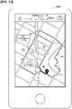
- the margin time described above may also be displayed, as shown in Figure 12 .
- the management server 20 when transmitting the signal indicating the walking routes R1 to R4 to the communication device 60, the management server 20 also transmits a signal indicating store information and event information associated with the walking routes R1 to R4, as well as the signal indicating the margin times associated with the walking routes R1 to R4, to the communication device 60.
- the display may exclude the display of store and event information on the walking route.
- store and event information on the walking route may be displayed only when the margin time is greater than or equal to a prescribed time.
- the management server 20 when transmitting a signal indicating the walking routes R1 to R4 to the communication device 60, the management server 20 also transmits a signal indicating store and event information on the walking routes R1 to R4, as well as a signal indicating the margin times associated with the walking routes R1 to R4 to the communication device 60.
- the management server 20 also transmits to the communication device 60 a signal indicating whether the margin time is shorter than the prescribed time to the communication device 60.
- the prescribed time is not particularly limited, but may be 30 seconds, for example.
- the processing circuits include programmed processing devices, such as processing devices including electronic circuits.
- the processing circuits also include such devices as application-specific integrated circuits (ASIC) and electronic components arranged to execute the described functions.
- ASIC application-specific integrated circuits
- the walking routes may be set from time to time in accordance with the current location of the user 70, rather than being established once in a final form. As shown in Figure 14 , the current location of the user 70 changes from one time to the next as the user advances from the state at time T to the state at time T+1.
- the walking route setting unit 217 may set the walking route in accordance with the current location of the user 70, which changes from time to time. The user 70 can thereby select a walking route that is different from the walking route that was initially selected.
- the entity that transmits to the communication device 60 prescribed signals for causing the communication device 60 to output (display) the plurality of walking routes, the margin times, etc. is described as the management server 20, but no limitation is implied thereby.
- the entity that transmits to the communication device 60 prescribed signals for causing the communication device 60 to output the plurality of walking routes, the margin times, etc. may be the communication device 60 itself or the taxi 40.
- a computer 607 installed in the communication device 60 may function as a location information acquisition unit 610, a required time calculation unit 611, a walking route calculation unit 612, a determination unit 613, and a walking route setting unit 614.
- the communication device 60 can be said to be a device that outputs to the communication device 60 prescribed signals for causing the communication device 60 to output the plurality of walking routes, the margin times, etc.
- a computer 404 installed in the taxi 40 may function as a location information acquisition unit 410, a required time calculation unit 411, a walking route calculation unit 412, a determination unit 413, and a walking route setting unit 414.
- the management server 20 the computer 607 installed in the communication device 60, and the computer 404 installed in the taxi 40 correspond to the movement assistance device.
Landscapes
- Engineering & Computer Science (AREA)
- Remote Sensing (AREA)
- Radar, Positioning & Navigation (AREA)
- Physics & Mathematics (AREA)
- General Physics & Mathematics (AREA)
- Business, Economics & Management (AREA)
- Human Resources & Organizations (AREA)
- Automation & Control Theory (AREA)
- Economics (AREA)
- Theoretical Computer Science (AREA)
- Strategic Management (AREA)
- Tourism & Hospitality (AREA)
- Entrepreneurship & Innovation (AREA)
- Development Economics (AREA)
- General Business, Economics & Management (AREA)
- Marketing (AREA)
- Operations Research (AREA)
- Quality & Reliability (AREA)
- Game Theory and Decision Science (AREA)
- Educational Administration (AREA)
- Mathematical Physics (AREA)
- Educational Technology (AREA)
- Traffic Control Systems (AREA)
- Navigation (AREA)
- Instructional Devices (AREA)
Abstract
Description
- The present invention relates to a movement assistance device and a movement assistance method.
- A technology for guiding a user to a meeting location where the user is to meet a vehicle is known from the prior art (Patent Document 1).
- Patent Document 1:
Japanese Laid-Open Patent Application No. 2013-130544 - However, the invention disclosed in
Patent Document 1 only presents the user with one route. The user cannot select a route other than the presented route, and thus has few options regarding movement. - In view of the problem described above, an object of the present invention is to provide a movement assistance device and a movement assistance method that present at least one route to a meeting location.
- A movement assistance device according to an embodiment of the present invention that acquires location information of a communication device in the possession of a user and location information of a vehicle dispatched in accordance with the user's dispatch request calculates, based on the location information of the vehicle, a first required time, which is the time required for the vehicle to arrive at a meeting location where the user who made the dispatch request is to board the vehicle; calculates, based on the location information of the communication device, a plurality of routes from a current location of the user to the meeting location; calculates a second required time, which is the time required to arrive at the meeting location from the current location of the user, for each of the plurality of calculated routes; determines that if the second required times are the same as or shorter than the first required time, the routes associated with the second required times are routes via which the vehicle could be met on time; and causes the communication device to output information that indicates the route or routes determined to be the route or routes via which the vehicle could be met on time.
- With the present invention, it is possible to present at least one route to a meeting location to the user.
-
-
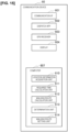
Figure 1 is an overall schematic view of amovement assistance system 10 according to an embodiment of the present invention. -
Figure 2 is a functional block diagram of amanagement server 20, acommunication device 60, and ataxi 40 according to the embodiment of the present invention. -
Figure 3 is a diagram describing a walking route according to the embodiment of the present invention. -
Figure 4 is a diagram explaining an example of a walking route displayed on adisplay 604. -
Figure 5A is a sequence diagram explaining one operation example of themovement assistance system 10 according to the embodiment of the present invention. -
Figure 5B is a sequence diagram explaining one operation example of themovement assistance system 10 according to the embodiment of the present invention. -
Figure 6 is a diagram explaining a first modified example of a walking route displayed on adisplay 604. -
Figure 7 is a diagram explaining a second modified example of a walking route displayed on adisplay 604. -
Figure 8 is a diagram explaining a third modified example of a walking route displayed on adisplay 604. -
Figure 9 is a diagram explaining a fourth modified example of a walking route displayed on adisplay 604. -
Figure 10 is a diagram explaining a fifth modified example of a walking route displayed on adisplay 604. -
Figure 11 is a diagram explaining a sixth modified example of a walking route displayed on adisplay 604. -
Figure 12 is a diagram explaining the sixth modified example of a walking route displayed on adisplay 604. -
Figure 13 is a diagram explaining the sixth modified example of a walking route displayed on adisplay 604. -
Figure 14 is a diagram explaining another example of a walking route displayed on adisplay 604. -
Figure 15 is a functional block diagram of a modified example of thecommunication device 60. -
Figure 16 is a functional block diagram of a modified example of a computer mounted on thetaxi 40. - An embodiment of the present invention is described below with reference to the figures. In the descriptions of the figures, identical parts have been assigned the same reference numerals, and their descriptions have been omitted.
- A configuration example of a
movement assistance system 10 according to the present embodiment will be described with reference toFigures 1 to 2 . As shown inFigure 1 , themovement assistance system 10 includes amanagement server 20, acommunication network 30,taxis 40 to 42, auser 70, and acommunication device 60 in the possession of theuser 70. InFigure 1 , there are three taxis, but no limitation is implied thereby. Themovement assistance system 10 may include four or more taxis. - The
management server 20 communicates with thetaxis 40 to 42 and thecommunication device 60 via thecommunication network 30. Themanagement server 20 is a general-purpose computer equipped with a CPU (Central Processing Unit) 21, amemory 22, a communication I/F 23, and astorage device 24; these constituent elements are electrically connected via a bus, etc., not shown in the figure. Themanagement server 20 is used in a dispatch service for thetaxis 40 to 42. Although the installation location of themanagement server 20 is not particularly limited, themanagement server 20 is installed, for example, in the control center of the business that operates thetaxis 40 to 42. - The
CPU 21 reads various programs stored in thestorage device 24, etc., into thememory 22 and executes various instructions contained in the programs. Thememory 22 is a storage medium such as a ROM (Read Only Memory), RAM (Random Access Memory), etc. Thestorage device 24 is a storage medium such as an HDD (Hard Disk Drive). Some (or all) of themovement assistance system 10, including the functions of themanagement server 20 described below may be provided by means of an application (Software as a Service (SaaS), etc.) located on thecommunication network 30. - The communication I/F 23 is implemented as hardware, such as a network adapter, various types of communication software, or a combination thereof, and is configured to realize wired or wireless communication via the
communication network 30, etc. Further, the communication I/F 23 functions as an input/output unit for sending and receiving data. - The
communication network 30 may be configured by a wireless and/or wired method, and thecommunication network 30 may include the Internet. In this embodiment, themanagement server 20, thetaxis 40 to 42, and thecommunication device 60 are connected to thecommunication network 30 by using a wireless communication method. - In this embodiment, the
taxis 40 to 42 are described as autonomous driving vehicles without a driver. Therefore, thetaxis 40 to 42 may be described as robot taxis or unmanned taxis. However, thetaxis 40 to 42 are not limited to autonomous driving vehicles without drivers. Thetaxis 40 to 42 may be ordinary vehicles with drivers. - The
user 70 requests (reserves) a taxi using thecommunication device 60. A vehicle dispatch application (hereinafter referred to simply as a vehicle dispatch app) used for reserving taxis is installed in thecommunication device 60, and theuser 70 requests a taxi using the vehicle dispatch app. - Next, with reference to
Figure 2 , detailed configurations of themanagement server 20, thetaxi 40, and thecommunication device 60 will be described. Although thetaxis Figure 2 , thetaxis taxi 40. - The
communication device 60 comprises a communication I/F 601, avehicle dispatch app 602, aGPS receiver 603, and adisplay 604. The communication I/F 601 has the same configuration as the communication I/F 23 (refer toFigure 1 ) and communicates with themanagement server 20 via thecommunication network 30. Thecommunication device 60 is a portable device such as a smartphone or a tablet. Thecommunication device 60 may also be a wearable device. Although not shown in the figure, thecommunication device 60 comprises a CPU (controller), memory, storage device, etc., in the same manner as themanagement server 20. - The
vehicle dispatch app 602 is used for requesting a taxi, as described above. Thevehicle dispatch app 602 functions as a user interface when theuser 70 requests a taxi. Thevehicle dispatch app 602 is realized by the CPU provided in thecommunication device 60 reading and executing a dedicated application program from a storage device provided in thecommunication device 60. When theuser 70 requests a taxi, theuser 70 inputs a desired boarding location, boarding time, deboarding location, etc., into thevehicle dispatch app 602 to request a taxi. Thevehicle dispatch app 602 transmits a dispatch request to themanagement server 20 in accordance with the input from theuser 70. Further, thecommunication device 60 displays on thedisplay 604 various types of information (dispatch request receipt, scheduled arrival time, scheduled travel route, etc.) included in the signal returned from themanagement server 20 in response to the dispatch request. However, the method of realizing thevehicle dispatch app 602 is not limited in this way. For example, thecommunication device 60 may access a server that provides the functions of thevehicle dispatch app 602, receive the functions provided, and display the results of executing the functions transmitted from the server in a browser. - The location information of the
communication device 60 acquired by theGPS receiver 603 is transmitted to themanagement server 20 at any given time. - The
taxi 40 is equipped with a communication I/F 401, a vehicle ECU (Electronic Control Unit) 402, and aGPS receiver 403. The communication I/F 401 has the same configuration as the communication I/F 23 and the communication I/F 601, and communicates with themanagement server 20 via thecommunication network 30. Thevehicle ECU 402 is a computer for controlling thetaxi 40. Thevehicle ECU 402 controls various actuators (brake actuator, accelerator pedal actuator, steering actuator, etc.) based on the commands received from themanagement server 20. The location information of thetaxi 40 acquired by theGPS receiver 403 is transmitted to themanagement server 20 at any given time. - As shown in the block diagram of
Figure 2 , the CPU 21 (the controller) of themanagement server 20 is provided with, as examples of the plurality of functions, a vehicledispatch acceptance unit 211, anassignment unit 212, a locationinformation acquisition unit 213, a requiredtime calculation unit 214, a walkingroute calculation unit 215, adetermination unit 216, and a walkingroute setting unit 217. As shown inFigure 2 , amap database 241 and aclient database 242 are stored in thestorage device 24 of themanagement server 20. - The map information required for route guidance, such as road information and facility information, is stored in the
map database 241. The map information includes the number of lanes on a road, road width information, and road undulation information. The map information also includes road signs indicating the speed limit, one-way streets, etc., as well as road markings indicating pedestrian crossings, lane markings, etc. The map information may also include information related to road structures (for example, traffic signals and telephone poles), buildings, and other facilities. - The
client database 242 stores account information, such as the ID of theuser 70, taxi usage history, and attributes of theuser 70. - The
dispatch acceptance unit 211 accepts a dispatch request from theuser 70 entered into thecommunication device 60. Thedispatch acceptance unit 211 has the function of notifying thecommunication device 60 of the acceptance of the dispatch request from theuser 70, as well as of the scheduled arrival time to the boarding location, the scheduled travel route to the boarding location, etc. - The
assignment unit 212 assigns a suitable taxi from among the plurality oftaxis 40 to 42 (refer toFigure 1 ) based on the accepted dispatch request. For example, for reasons of efficiency, thedispatch acceptance unit 211 can assign the unoccupied taxi that, of the plurality oftaxis 40 to 42, is closest to the boarding location desired by theuser 70. In the present embodiment, it is assumed that thetaxi 40 has been assigned. - The
assignment unit 212 also sets a travel route from the current location of thetaxi 40 to the boarding location desired by theuser 70 by referencing themap database 241 and sends an instruction to thetaxi 40 to travel to the boarding location desired by theuser 70 via the set travel route. The travel route calculated by theassignment unit 212 is, for example, the route via which the boarding location desired by theuser 70 can be reached from the current location of thetaxi 40 in the shortest amount of time. Theassignment unit 212 outputs the set travel route to the requiredtime calculation unit 214. - The location
information acquisition unit 213 acquires the location information of theuser 70 from thecommunication device 60 and acquires location information of thetaxi 40 from thetaxi 40. The location information of theuser 70 means the location information of thecommunication device 60 in the possession of theuser 70. The locationinformation acquisition unit 213 outputs the acquired location information to the requiredtime calculation unit 214. - The required time calculation unit 214 (the first required time calculation unit, the second required time calculation unit) uses the travel route acquired from the
assignment unit 212 and the location information of thetaxi 40 acquired from the locationinformation acquisition unit 213 to calculate a first required time or time required for thetaxi 40 to arrive at the boarding location desired by theuser 70 from its current location The requiredtime calculation unit 214 outputs this calculated first required time to thedetermination unit 216. - The walking
route calculation unit 215 uses themap database 241 and the location information of theuser 70 acquired from the locationinformation acquisition unit 213 to calculate walking routes. In the present embodiment, a walking route is a route that theuser 70 can take on foot from the current location of theuser 70 to the boarding location. The walkingroute calculation unit 215 calculates a plurality of walking routes to the boarding location. The requiredtime calculation unit 214 also calculates a second required time, which is the time required for theuser 70 to arrive at the boarding location from his or her current location, for each of the plurality of walking routes calculated by the walkingroute calculation unit 215. The requiredtime calculation unit 214 outputs these calculated second required times to thedetermination unit 216. Each second required time is associated with the corresponding walking route. - The
determination unit 216 determines whether theuser 70 can be on time to meet thetaxi 40 using the first required time and the second required times obtained from the requiredtime calculation unit 214. For example, if a second required time is shorter than the first required time, thedetermination unit 216 determines that theuser 70 can be on time to meet thetaxi 40. Further, if a second required time and the first required time are the same, thedetermination unit 216 determines that theuser 70 can be on time to meet thetaxi 40. Here, "a second required time and the first required time are the same" does not imply an exact equivalence. "A second required time and the first required time are the same" means that the times are essentially the same (i.e., approximately the same) and that a difference of several seconds is negligible. - In the present embodiment, "the
user 70 can be on time to meet thetaxi 40" means that theuser 70 can arrive at the boarding location ahead of thetaxi 40. Alternatively, "theuser 70 can be on time to meet thetaxi 40" can mean that theuser 70 and thetaxi 40 may arrive at the boarding location at the same time (or approximately the same time). - If it is determined that the
user 70 can be on time to meet thetaxi 40, thedetermination unit 216 outputs the walking routes associated with the second required times used to arrive at this determination to the walkingroute setting unit 217. - The walking
route setting unit 217 sets the walking routes acquired from thedetermination unit 216 as the walking routes to be presented to theuser 70 and transmits a signal indicating the set walking routes to thecommunication device 60 in the possession of theuser 70 via the communication I/F 23. - Details of the walking route will now be described with reference to
Figure 3 . - It is assumed that the
user 70 shown inFigure 3 requests a taxi using thevehicle dispatch app 602.Reference numeral 80 inFigure 3 indicates the boarding location desired by theuser 70. That is,reference numeral 80 indicates the location where theuser 70 is to meet thetaxi 40.Reference numeral 80 is hereafter designated as meetinglocation 80. Thetaxi 40 travels to themeeting location 80 in order to board theuser 70 based on a command received from themanagement server 20. Thetaxi 40 is omitted inFigure 3 . - As described above, the required
time calculation unit 214 uses the travel route acquired from theassignment unit 212 and the location information of thetaxi 40 acquired from the locationinformation acquisition unit 213 to calculate a first required time, which is the time required for thetaxi 40 to arrive at themeeting location 80 from its current location. In the following description, it is assumed that the first required time has been calculated as 8 minutes. - As shown in
Figure 3 , the walkingroute calculation unit 215 uses themap database 241 and the location information of theuser 70 acquired from the locationinformation acquisition unit 213 to calculate walking routes R1 to R4. Walking routes R1 to R4 are routes that theuser 70 can take on foot from the current location of theuser 70 to themeeting location 80. - The required
time calculation unit 214 calculates a second required time, which is the time required to arrive at themeeting location 80 from the current location of theuser 70, for each of the walking routes R1 to R4 calculated by the walkingroute calculation unit 215. It is assumed only inFigure 3 that the second required times for traversing the walking routes are calculated as 5 minutes for the walking route R1, 6 minutes for the walking route R2, 7 minutes for the walking route R3, and 9 minutes for the walking route R4. - The
determination unit 216 determines whether theuser 70 can be on time to meet thetaxi 40 using the first required time (8 minutes) and the second required times (R1: 5 minutes, R2: 6 minutes, R3: 7 minutes, R4: 9 minutes) acquired from the requiredtime calculation unit 214. Since thetaxi 40 will arrive at themeeting location 80 in 8 minutes, if theuser 70 can arrive at themeeting location 80 within 8 minutes, the user can meet thetaxi 40 on time. - Thus, the
determination unit 216 determines whether there is a walking route via which themeeting location 80 can be reached within the first required time. For example, thedetermination unit 216 compares the first required time and a second required time, and if this second required time is shorter than the first required time, determines that the walking route associated with this second required time is a walking route via which themeeting location 80 can be reached within the first required time. - In
Figure 3 , since the second required times (R1: 5 minutes, R2: 6 minutes, R3: 7 minutes) associated with the walking routes R1 to R3 are shorter than the first required time (8 minutes), thedetermination unit 216 determines that the walking routes R1 to R3 are the walking routes via which themeeting location 80 can be reached within the first required time. Since the second required time (9 minutes) associated with the walking route R4 is longer than the first required time (8 minutes), on the other hand, thedetermination unit 216 determines that the walking route R4 cannot be used to arrive at themeeting location 80 within the first required time. Thedetermination unit 216 outputs the walking routes R1 to R3 (the walking routes via which theuser 70 can meet thetaxi 40 on time) to the walkingroute setting unit 217. Walking route R4, on the other hand, is deleted since it cannot be used to arrive at themeeting location 80 within the first required time. - The walking
route setting unit 217 then sets the walking routes R1 to R3 acquired from thedetermination unit 216 as the walking routes to be presented to theuser 70 and transmits a signal indicating the set walking routes R1 to R3 to thecommunication device 60 in the possession of theuser 70 via the communication I/F 23. - As shown in
Figure 4 , walking routes R1 to R3 acquired from themanagement server 20 are displayed on thedisplay 604 of thecommunication device 60. Regardless of which walking route of the walking routes R1 to R3 theuser 70 selects, theuser 70 can be on time to meet thetaxi 40. By means of the present embodiment, a plurality of the walking routes R1 to R3 can be presented to theuser 70 via which thetaxi 40 can be met on time; thus, theuser 70 can select his or her preferred route from the plurality of the walking routes R1 to R3. This increases the number of options that theuser 70 can choose from when he/she departs for themeeting location 80. When theuser 70 selects his/her preferred route, the user is guided along this route to themeeting location 80, as with a well-known navigation system. - An example of the operation of the
movement assistance system 10 will now be explained with reference to the sequence charts ofFigures 5A-5B . - In Step S101, the
user 70 requests a taxi using thevehicle dispatch app 602. The process proceeds to Step S103, in which thedispatch acceptance unit 211 accepts the dispatch request of theuser 70. The process proceeds to Step S105, in which theassignment unit 212 assigns an appropriate taxi from among the plurality oftaxis 40 to 42 (refer toFigure 1 ) based on the accepted dispatch request. The process proceeds to Step S107, in which theassignment unit 212 references themap database 241 and sets the travel route from the current location of thetaxi 40 to the boarding location desired by the user 70 (meeting location 80). - The process proceeds to Step S109, in which the
management server 20 transmits the set travel route to thetaxi 40. The process then proceeds to Step S111, in which thetaxi 40 travels to themeeting location 80 desired by theuser 70 via the acquired travel route. - In Step S113, the
communication device 60 transmits the location information of thecommunication device 60 acquired by theGPS receiver 603 to themanagement server 20. In Step S115, thetaxi 40 transmits the location information of thetaxi 40 acquired by theGPS receiver 403 to themanagement server 20. In Step S117, themanagement server 20 receives the location information transmitted from thecommunication device 60 and thetaxi 40. The process of Step S115 is repeated until thetaxi 40 arrives at the meeting location 80 (Step S119). - The process proceeds to Step S121, in which the required
time calculation unit 214 calculates the first required time, i.e., the time required for thetaxi 40 to arrive at themeeting location 80 from its current location. The process proceeds to Step S123, in which the walkingroute calculation unit 215 calculates the walking routes R1 to R4 (refer toFigure 3 ) using themap database 241 and the location information of theuser 70 acquired in Step S117. - The process proceeds to Step S125, in which the
determination unit 216 determines whether any of the walking routes R1 to R4 calculated in Step S123 cannot be used to arrive at themeeting location 80 within the first required time. If there is a walking route R4, as is shown inFigure 3 , via which it is not possible to arrive at themeeting location 80 within the first required time (YES in Step S125), the process proceeds to Step S127, and the walking route R4 is deleted. If, on the other hand, there are the walking routes R1 to R3 via which themeeting location 80 can be reached within the first required time (NO in Step S125), the walkingroute setting unit 217 sets the walking routes R1 to R3 as the walking routes to be presented to the user 70 (Step S129). The process proceeds to Step S131, in which the walkingroute setting unit 217 transmits a signal indicating the set walking routes R1 to R3 to thecommunication device 60 in the possession of theuser 70 via the communication I/F 23. - The process proceeds to Step S133, in which the
communication device 60 receives a signal indicating the walking routes R1 to R3 transmitted from themanagement server 20. The process proceeds to Step S135, in which walking routes R1 to R3 are displayed on thedisplay 604, as shown inFigure 4 . The process of Step S113 is repeated until theuser 70 arrives at the meeting location 80 (Step S137). - As described above, the following actions and effects can be achieved by means of the
management server 20 according to the present embodiment. - The
management server 20 is equipped with the locationinformation acquisition unit 213, the first required time calculation unit (the required time calculation unit 214), the route calculation unit (the walking route calculation unit 215), the second required time calculation unit (the required time calculation unit 214), thedetermination unit 216, and the output unit (the communication I/F 23). - The location
information acquisition unit 213 acquires the location information of thecommunication device 60 in the possession of theuser 70 as well as the location information of thetaxi 40 dispatched in accordance with the dispatch request of theuser 70. The first required time calculation unit calculates, based on the location information of thetaxi 40, the first required time or time required for thetaxi 40 to arrive at themeeting location 80 where theuser 70 who requested the dispatch is to board. - The route calculation unit calculates, based on the location information of the
communication device 60, a plurality of routes from the current location of theuser 70 to themeeting location 80. The second required time calculation unit calculates a second required time, which is the time required to arrive at the meeting location from the current location of the user, for each of the plurality of routes calculated by the route calculation unit. - If a second required time is the same as or shorter than the first required time, the
determination unit 216 determines that the route associated with the second required time is a route via which thetaxi 40 could be met on time. The output unit causes thecommunication device 60 to output information indicating the route or routes determined by thedetermination unit 216 to be thee route or routes via which thetaxi 40 could be met on time. - As a result, as shown in
Figure 4 , theuser 70 can be presented with the plurality of the walking routes R1 to R3 via which thetaxi 40 could be met on time, thereby allowing theuser 70 to select a preferred route from the plurality of the walking routes R1 to R3. This increases the number of options that theuser 70 can choose from when the user departs for themeeting location 80. - The first modified example of the present embodiment will now be described with reference to
Figure 6 . - As shown in
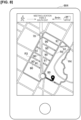
Figure 6 , when themanagement server 20 transmits a signal indicating the walking routes R1 to R4 to thecommunication device 60, the management server may also transmit a signal indicating the second required times associated with the walking routes R1 to R4 to thecommunication device 60. - As a result, as shown in
Figure 6 , the walking routes R1 to R4 acquired from themanagement server 20 and the second required times associated with the walking routes R1 to R4 are displayed on thedisplay 604 of thecommunication device 60. In the following description, it is assumed that the second required times for traversing the walking routes have been calculated as 5 minutes for the walking route R1, 6 minutes for the walking route R2, 7 minutes for the walking route R3, and 8 minutes for the walking route R4. - In the same manner as the example shown in
Figure 3 , the walking routes R1 to R3 are walking routes via which themeeting location 80 can be reached within the first required time. Further, inFigure 6 onwards, walking route R4 is also a walking route via which themeeting location 80 can be reached within the first required time. Because the second required time (8 minutes) associated with the walking route R4 is the same as the first required time (8 minutes), thedetermination unit 216 determines that walking route R4 is a walking route via which themeeting location 80 can be reached within the first required time. - As shown in
Figure 6 , because walking routes R1 to R4 and the second required times associated with the walking routes R1 to R4 are displayed on thedisplay 604, theuser 70, when choosing between the walking routes, can ascertain at a glance the associated walking times. Theuser 70 can select his or her preferred route from the walking routes R1 to R4 in consideration of the walking time. - The second modified example of the present embodiment will now be described with reference to
Figure 7 . - In the second modified example, the required
time calculation unit 214 calculates a margin time. The margin time is the time in minutes that indicates how much longer it will take thetaxi 40 to arrive at themeeting location 80 after theuser 70 has arrived at themeeting location 80. The margin time is calculated by subtracting the second required time from the first required time (8 minutes). Since the second required times to traverse the walking routes are 5 minutes for the walking route R1, 6 minutes for the walking route R2, 7 minutes for the walking route R3, and 8 minutes for the walking route R4, as shown inFigure 7 , the margin times associated with traversing the walking routes are 3 minutes for the walking route R1, 2 minutes for the walking route R2, 1 minute for the walking route R3, and 0 minutes for the walking route R4. The margin times are associated with the corresponding walking routes in the same manner as are the second required times. - The longer the margin time, the less hurried the pace of the
user 70 as he/she moves toward themeeting location 80. The shorter the margin time, on the other hand, the less extra time available to theuser 70. For example, if the margin time is 0 minutes, as is the case with the walking route R4, theuser 70 understands that there is no time to waste; theuser 70 may therefore avoid selecting the walking route R4, or may decide to select walking route R4 and set out immediately, moving quickly, not stopping along the way, heeding the time, etc., as he/she moves toward themeeting location 80. - In the second modified example, when the
management server 20 transmits a signal indicating the walking routes R1 to R4 to thecommunication device 60, the management server also transmits a signal indicating the margin times associated with the walking routes R1 to R4 to thecommunication device 60. - As a result, as shown in
Figure 7 , the walking routes R1 to R4 acquired from themanagement server 20 and the margin times associated with the walking routes R1 to R4 are displayed on thedisplay 604 of thecommunication device 60. The display allows theuser 70 to ascertain at a glance the margin time for each walking route that may be selected. Thus, theuser 70 can base their selection of walking routes R1 to R4 on the margin time. - The third modified example of the present embodiment will now be described with reference to
Figure 8 . - When the
user 70 departs for themeeting location 80, the user may be able to take side roads, branch roads, etc., depending the condition of the roads.Reference numerals Figure 8 are arrows that indicate the directions that can be taken at side roads and branch roads. Consider the walking routes R1 and R3, for example. At the side and branch roads between the walking routes R1 and R3,arrow 91 indicates that it would be possible to take the walking route R1 to the walking route R3, or the walking route R3 to the walking route R1. More specifically,arrow 91 indicates that whether the user were to take the walking route R1 to the walking route R3 or the walking route R3 to the walking route R1, it would be possible to meet thetaxi 40 on time. - In contrast,
arrows 90 indicate that it is possible to take the walking route R3 to the walking route R1, but not the walking route R1 to the walking route R3. More specifically,arrows 90 indicate that if the user were to take the walking route R3 to the walking route R1, it would be possible to meet thetaxi 40 on time, but if the user were to take the walking route R1 to the walking route R3, it would not be possible to meet thetaxi 40 on time. - The same applies to
arrows arrows - In the third modified example, when transmitting a signal indicating the walking routes R1 to R4 to the
communication device 60, themanagement server 20 also transmits a signal indicating the arrows that indicate the directions that can be taken at the side roads and branch roads. - As a result, as shown in
Figure 8 , the walking routes R1 to R4 acquired from themanagement server 20 andarrows display 604 of thecommunication device 60. The display allows theuser 70 to ascertain at a glance the direction to take at the side roads and branch roads, and how to proceed on the preferred side roads and branch roads. This gives the user more movement-related options when theuser 70 departs for themeeting location 80. - The fourth modified example of the present embodiment will now be described with reference to
Figure 9 . - Roads available to the
user 70 may be hilly, have stairs, pedestrian crossing bridges, etc. Hills, stairs, pedestrian crossing bridges, etc., are elements that impose a greater burden of movement compared with flat routes. Depending on theuser 70, there may be a need to avoid traversing hills, stairs, pedestrian crossing bridges, etc. As an example, such a need may arise for auser 70 who uses a wheelchair. In Fourth Modified example, if a walking route set by the walkingroute setting unit 217 includes hills, stairs, pedestrian crossing bridges, etc., when themanagement server 20 transmits a signal indicating the walking routes R1 to R4 to thecommunication device 60, a signal indicating that the presence of the hills, stairs, pedestrian crossing bridges, etc., is also transmitted to thecommunication device 60. - The particulars will be described with reference to
Figure 9 . It is assumed that there are stairs on the walking route R4 shown inFigure 9 . In this case, when transmitting the signal indicating the walking routes R1 to R4 to thecommunication device 60, themanagement server 20 also transmits a signal indicating that there are stairs on the walking route R4 to thecommunication device 60. When thecommunication device 60 receives these signals, as shown inFigure 9 , the walking routes R1 to R3 are displayed as ordinary lines, whereas the walking route R4 is displayed as a dotted line on thedisplay 604. If it is set in advance, as a display rule, that walking routes indicated by dotted lines mean that there are stairs, theuser 70 can ascertain at a glance that there are stairs on the walking route R4. As described above, in the case that theuser 70 uses a wheelchair, theuser 70 can avoid stairs by selecting the walking routes R1 to R3. - The walking route on which there are stairs is indicated by the dotted line in
Figure 9 , but the display example is not limited in this way. Walking routes on which there are stairs may be displayed with a thick line or a one-dotted chain line. Walking routes on which there are stairs and flat walking routes may be distinguished by color. As an example, walking routes with stairs may be displayed in red, while flat walking routes are displayed in green. Further, the display may be different for hills, stairs, and pedestrian crossing bridges. - Further, the management server 20 (the determination unit 216) can refer to the
map database 241 in order to determines whether there are hills, stairs, pedestrian crossing bridges, etc., on the walking routes R1 to R4. The means of transportation of theuser 70 includes walking, use of a wheelchair, bicycling, and running (running). - The
management server 20 may compare the heights of the walking routes R1 to R4 (plurality of routes) with respect to a horizontal plane in order to determine if there is an element that imposes a high burden of movement. Specifically, themanagement server 20 may determine that there is an element that imposes a high burden of movement when the height of a certain route (the walking route R4 ofFigure 9 ) with respect to a horizontal plane is higher or lower than that of another route (the walking routes R1 to R3 ofFigure 9 ). - The fifth modified example of the present embodiment will now be described with reference to
Figure 10 . - In the fourth modified example described above, if there are stairs on the walking route R4, the walking route R4 is displayed using a dotted line. The method of presenting to the
user 70 that the walking route R4 has stairs is not limited in this way. As shown inFigure 10 , a balloon indicating the walking route R4 may display the words "with stairs." By use of this display, theuser 70 can ascertain at a glance that there are stairs on the walking route R4. - As an operation example of the
management server 20 in the fifth modified example, when transmitting the signal indicating the walking routes R1 to R4 to thecommunication device 60, themanagement server 20 also transmits a signal (signals for displaying a balloon) indicating that there are stairs on the walking route R4 to thecommunication device 60. - The sixth modified example of the present embodiment will now be described with reference to
Figure 11 . - Roads available to the
user 70 include sidewalks, roads in parks, station yards, etc. There are cases in which stores such as convenience stores are present, or events such as product exhibits and festivals taking place in such areas. For example, as shown inFigure 11 , it is assumed that a convenience store is present on the walking route R3, that a product exhibition is taking place on the walking route R1, and that a festival is being held on the walking route R4. - In this case, when transmitting the signal indicating the walking routes R1 to R4 to the
communication device 60, themanagement server 20 also transmits a signal indicating store information and event information on the walking routes R1 to R4 to thecommunication device 60. By means of thecommunication device 60 receiving these signals, as shown inFigure 11 , balloons indicating that a convenience store is present on the walking route R3, that a product exhibition is taking place on the walking route R1, and that a festival is being held on the walking route R4, are displayed on thedisplay 604. - Users who like to purchase local specialty goods at product exhibitions can satisfy their needs by selecting walking route R1. Alternatively, by selecting walking route R4, users who like to see festivals would be able to do so as they travel toward the
meeting location 80. In this manner, when a plurality of the walking routes R1 to R4 is displayed, store and event information associated with these walking routes can also be displayed, thereby providing theuser 70 with a wide range of options. - The management server 20 (information acquisition unit) can obtain information pertaining to stores, such as convenience stores, by referring to the
map database 241. Further, with regard to event information such as product exhibitions and festivals, the management server 20 (information acquisition unit) can use the location information of theuser 70 to search for and obtain event information on the Internet for the area where theuser 70 is located. Both store information and event information may be displayed, as shown inFigure 11 , or only one may be displayed. - Further, when store information and event information is displayed on the walking routes using balloons, the margin time described above may also be displayed, as shown in
Figure 12 . This makes it easier for theuser 70 to arrive at such decisions as, "I can't stop at the convenience store on the walking route R3 since it only gives me one extra minute, but I can stop at the product exhibition on the walking route R1 since it gives me three extra minutes." Note that. As an operation example of themanagement server 20 in this case, when transmitting the signal indicating the walking routes R1 to R4 to thecommunication device 60, themanagement server 20 also transmits a signal indicating store information and event information associated with the walking routes R1 to R4, as well as the signal indicating the margin times associated with the walking routes R1 to R4, to thecommunication device 60. - In the display example of
Figure 12 , a festival is being held along walking route R4, but the margin time here is 0 minutes, so that even if theuser 70 were to select walking route R4 to see the festival, there would be no time to do so. Therefore, as shown inFigure 13 , if the margin time is shorter than a prescribed time, the display may exclude the display of store and event information on the walking route. In other words, store and event information on the walking route may be displayed only when the margin time is greater than or equal to a prescribed time. As an operation example of themanagement server 20 in this case, when transmitting a signal indicating the walking routes R1 to R4 to thecommunication device 60, themanagement server 20 also transmits a signal indicating store and event information on the walking routes R1 to R4, as well as a signal indicating the margin times associated with the walking routes R1 to R4 to thecommunication device 60. Themanagement server 20 also transmits to the communication device 60 a signal indicating whether the margin time is shorter than the prescribed time to thecommunication device 60. The prescribed time is not particularly limited, but may be 30 seconds, for example. - Each of the functions described in the embodiments above may be implemented by means of one or more processing circuits. The processing circuits include programmed processing devices, such as processing devices including electronic circuits. The processing circuits also include such devices as application-specific integrated circuits (ASIC) and electronic components arranged to execute the described functions.
- Embodiments of the present invention have been described above, but the descriptions and figures that form part of this disclosure should not be understood as limiting the present invention. From this disclosure, various alternative embodiments, examples, and operating techniques should be apparent to those skilled in the art.
- The walking routes may be set from time to time in accordance with the current location of the
user 70, rather than being established once in a final form. As shown inFigure 14 , the current location of theuser 70 changes from one time to the next as the user advances from the state at time T to the state attime T+ 1. The walkingroute setting unit 217 may set the walking route in accordance with the current location of theuser 70, which changes from time to time. Theuser 70 can thereby select a walking route that is different from the walking route that was initially selected. - Further, in the embodiment described above, the entity that transmits to the
communication device 60 prescribed signals for causing thecommunication device 60 to output (display) the plurality of walking routes, the margin times, etc., is described as themanagement server 20, but no limitation is implied thereby. The entity that transmits to thecommunication device 60 prescribed signals for causing thecommunication device 60 to output the plurality of walking routes, the margin times, etc., may be thecommunication device 60 itself or thetaxi 40. - When the
communication device 60 is set as the entity that transmits to thecommunication device 60 prescribed signals for causing thecommunication device 60 to output the plurality of walking routes, the margin times, etc., as shown inFigure 15 , acomputer 607 installed in thecommunication device 60 may function as a locationinformation acquisition unit 610, a requiredtime calculation unit 611, a walkingroute calculation unit 612, adetermination unit 613, and a walkingroute setting unit 614. These functions of the locationinformation acquisition unit 610, the requiredtime calculation unit 611, the walkingroute calculation unit 612, thedetermination unit 613, and the walkingroute setting unit 614 are the same as those of the locationinformation acquisition unit 213, the requiredtime calculation unit 214, the walkingroute calculation unit 215, thedetermination unit 216, and the walkingroute setting unit 217 shown inFigure 2 . In this case, thecommunication device 60 can be said to be a device that outputs to thecommunication device 60 prescribed signals for causing thecommunication device 60 to output the plurality of walking routes, the margin times, etc. - On the other hand, when the
taxi 40 is set as the entity that transmits to thecommunication device 60 prescribed signals for causing thecommunication device 60 to output the plurality of walking routes, the margin times, etc., as shown inFigure 16 , acomputer 404 installed in thetaxi 40 may function as a locationinformation acquisition unit 410, a requiredtime calculation unit 411, a walkingroute calculation unit 412, adetermination unit 413, and a walkingroute setting unit 414. These functions of the locationinformation acquisition unit 410, the requiredtime calculation unit 411, the walkingroute calculation unit 412, thedetermination unit 413, and the walkingroute setting unit 414 are the same as those of the locationinformation acquisition unit 213, the requiredtime calculation unit 214, the walkingroute calculation unit 215, thedetermination unit 216, and the walkingroute setting unit 217 shown inFigure 2 . Themanagement server 20, thecomputer 607 installed in thecommunication device 60, and thecomputer 404 installed in thetaxi 40 correspond to the movement assistance device. - The entire contents of
Japanese Patent Application No. 2020-060535 (Filing date: March 30, 2020 -
- 10
- Movement assistance system
- 20
- Management server
- 30
- Communication network
- 40-42
- Taxis
- 60
- Communication device
- 70
- User
- 211
- Dispatch acceptance unit
- 212
- Assignment unit
- 213
- Location information acquisition unit
- 214
- Required time calculation unit
- 215
- Walking route calculation unit
- 216
- Determination unit
- 217
- Walking route setting unit
- 241
- Map database
Claims (6)
- A movement assistance device comprising:a location information acquisition unit configured to acquire location information of a communication device possessed by a user and location information of a vehicle dispatched in accordance with a dispatch request by the user;a first required time calculation unit configured to calculate, based on location information of the vehicle, a first required time until the vehicle arrives at a meeting location where the user who made the dispatch request is to board;a route calculation unit configured to calculate, based on the location information of the communication device, a plurality of routes from a current location of the user to the meeting location;a second required time calculation unit configured to calculate a second required time from the current location of the user to the meeting location, for each of the plurality of routes calculated by the route calculation unit;a determination unit configured to determine the route associated with the second required time is a route in which the vehicle could be met on time when the second required time is the same as or shorter than the first required time; andan output unit configured to cause the communication device to output information indicating the route or routes determined by the determination unit to be the route or routes via which the vehicle could be met on time.
- The movement assistance device according to claim 1, whereinthe determination unit is configured to determine whether the route via which the vehicle could be met on time includes an element that imposes a high burden of movement, andthe output unit is configured to cause the communication device to output information indicating the element with the high burden of movement upon the determination unit determining a presence of the element that imposes a high burden of movement.
- The movement assistance device according to claim 1 or 2, further comprisingan information acquisition unit is configured to acquire store information or event information associated with the route via which the vehicle could be met on time, whereinthe output unit is configured to cause the communication device to output the store information or the event information acquired by the information acquisition unit.
- The movement assistance device according to claim 3, whereinthe first required time calculation unit is configured to subtract the second required time from the first required time to calculate a margin time, andthe output unit is configured to cause the communication device to output information indicating the margin time calculated by the first required time calculation unit.
- The movement assistance device according to claim 4, wherein
the output unit is configured to cause the communication device to output the store information or the event information pertaining to a route associated with the margin time only if the margin time is greater than or equal to a prescribed time. - A movement assistance method comprising:acquiring location information of a communication device in possessed by a user and location information of a vehicle dispatched in accordance with dispatch request by the user;calculating, based on the location information of the vehicle, a first required time until the vehicle arrives at a meeting location where the user who made the dispatch request is to board the vehicle;calculating, based on the location information of the communication device, a plurality of routes from a current location of the user to the meeting location;calculating a second required time from the current location of the user to the meeting location, for each of the plurality of calculated routes;determining the route associated with the second required time is a route in which the vehicle could be met on time when the second required time is the same as or shorter than the first required time; andcausing the communication device to output information that indicates the route or routes determined to be the route or routes in which the vehicle could be met on time.
Applications Claiming Priority (2)
| Application Number | Priority Date | Filing Date | Title |
|---|---|---|---|
| JP2020060535 | 2020-03-30 | ||
| PCT/IB2021/000168 WO2021198767A1 (en) | 2020-03-30 | 2021-03-22 | Movement assistance device and movement assistance method |
Publications (3)
| Publication Number | Publication Date |
|---|---|
| EP4131215A1 true EP4131215A1 (en) | 2023-02-08 |
| EP4131215A4 EP4131215A4 (en) | 2023-10-18 |
| EP4131215B1 EP4131215B1 (en) | 2024-09-04 |
Family
ID=77928148
Family Applications (1)
| Application Number | Title | Priority Date | Filing Date |
|---|---|---|---|
| EP21777926.3A Active EP4131215B1 (en) | 2020-03-30 | 2021-03-22 | Movement assistance device and movement assistance method |
Country Status (5)
| Country | Link |
|---|---|
| US (1) | US12140440B2 (en) |
| EP (1) | EP4131215B1 (en) |
| JP (1) | JP7327655B2 (en) |
| CN (1) | CN115335883B (en) |
| WO (1) | WO2021198767A1 (en) |
Families Citing this family (1)
| Publication number | Priority date | Publication date | Assignee | Title |
|---|---|---|---|---|
| JP2023179913A (en) * | 2022-06-08 | 2023-12-20 | 株式会社ゼンリン | Control system and program |
Family Cites Families (42)
| Publication number | Priority date | Publication date | Assignee | Title |
|---|---|---|---|---|
| JP3384172B2 (en) * | 1995-02-28 | 2003-03-10 | 株式会社デンソー | Travel guide device for vehicles |
| JP2002107161A (en) * | 2000-10-03 | 2002-04-10 | Matsushita Electric Ind Co Ltd | Route guidance device for moving objects |
| JP2005275678A (en) | 2004-03-24 | 2005-10-06 | Hitachi Software Eng Co Ltd | Vehicle dispatching service support method, and device |
| JP2006003169A (en) * | 2004-06-16 | 2006-01-05 | Aisin Aw Co Ltd | Route guidance system and program for route guidance method |
| JP4161969B2 (en) * | 2005-01-24 | 2008-10-08 | 株式会社デンソー | Navigation device and program |
| JP2007163274A (en) * | 2005-12-13 | 2007-06-28 | Denso Corp | Navigation device |
| JP2007322155A (en) | 2006-05-30 | 2007-12-13 | Denso Corp | Navigation device and program |
| JP4450028B2 (en) * | 2007-07-23 | 2010-04-14 | 株式会社デンソー | Route guidance device |
| JP2009257991A (en) * | 2008-04-18 | 2009-11-05 | Denso Corp | Car navigation system |
| KR101314308B1 (en) * | 2010-02-26 | 2013-10-02 | 한국전자통신연구원 | Apparatus for managing traffic using previous navigational preference patterns based navigational situation and method thereof |
| US8700327B2 (en) * | 2010-04-27 | 2014-04-15 | Honda Motor Co., Ltd. | Method of determining routes for use in navigation |
| JP2013130544A (en) | 2011-12-22 | 2013-07-04 | Aisin Aw Co Ltd | Information providing-system, information providing-device, information providing-method, and computer program |
| EP2927847A1 (en) * | 2014-03-31 | 2015-10-07 | Amadeus S.A.S. | Journey planning method and system |
| US20160320195A1 (en) * | 2015-04-29 | 2016-11-03 | Ford Global Technologies, Llc | Ride-sharing long-term ride-share groups |
| CN105575104B (en) * | 2015-12-17 | 2018-03-02 | 小米科技有限责任公司 | Taxi-hailing software processing method and processing device |
| US20170176192A1 (en) * | 2015-12-22 | 2017-06-22 | Veniam, Inc. | Systems and methods to extrapolate high-value data from a network of moving things, for example including a network of autonomous vehicles |
| US10380509B2 (en) * | 2016-02-03 | 2019-08-13 | Operr Technologies, Inc. | Method and system for providing an individualized ETA in the transportation industry |
| JP6365602B2 (en) | 2016-07-14 | 2018-08-01 | トヨタ自動車株式会社 | Schedule management device |
| US9739627B1 (en) * | 2016-10-18 | 2017-08-22 | Allstate Insurance Company | Road frustration index risk mapping and mitigation |
| US10489721B2 (en) * | 2017-05-23 | 2019-11-26 | Uatc, Llc | Path segment risk regression system for on-demand transportation services |
| CN108986446A (en) * | 2017-06-01 | 2018-12-11 | 北京嘀嘀无限科技发展有限公司 | It gets on the bus an acquisition methods, driver passenger's interconnected method and device, system |
| JP6851402B2 (en) * | 2017-06-01 | 2021-03-31 | ベイジン ディディ インフィニティ テクノロジー アンド ディベロップメント カンパニー リミティッド | Methods and systems for providing transportation services |
| JP2019016290A (en) | 2017-07-10 | 2019-01-31 | 富士通株式会社 | Traveling management method, traveling management device and traveling management program |
| CN107403560B (en) * | 2017-08-17 | 2019-11-19 | 北京经纬恒润科技有限公司 | A kind of method and device for recommending Entrucking Point |
| WO2019079750A1 (en) * | 2017-10-19 | 2019-04-25 | Gerard Dirk Smits | Methods and systems for navigating a vehicle including a novel fiducial marker system |
| US20190120640A1 (en) * | 2017-10-19 | 2019-04-25 | rideOS | Autonomous vehicle routing |
| US20190156254A1 (en) * | 2017-11-21 | 2019-05-23 | GM Global Technology Operations LLC | Systems and methods for dynamically managing a shuttle fleet |
| JP6731006B2 (en) * | 2018-01-22 | 2020-07-29 | 株式会社Subaru | Vehicle calling system |
| JP2019196103A (en) * | 2018-05-10 | 2019-11-14 | 古野電気株式会社 | Automatic steering device, automatic steering method, and automatic steering program |
| JP7140849B2 (en) * | 2018-05-31 | 2022-09-21 | ニッサン ノース アメリカ,インク | Probabilistic Object Tracking and Prediction Framework |
| US20190390971A1 (en) * | 2018-06-25 | 2019-12-26 | Uber Technologies, Inc. | Determining cumulative estimated time for requested services |
| US11231280B2 (en) * | 2018-07-06 | 2022-01-25 | Inrix Inc. | Probabilistic parking routes |
| JP6836565B2 (en) | 2018-10-12 | 2021-03-03 | アンリツ株式会社 | Antenna device and measurement method |
| US11099020B2 (en) * | 2019-05-28 | 2021-08-24 | Here Global B.V. | Method and apparatus for optimizing intermodal route computations |
| US11994396B2 (en) * | 2019-05-29 | 2024-05-28 | Here Global B.V. | Method and apparatus for providing drop-off locations for passengers of a vehicle to reach different destinations via a multimodal route |
| US11692845B2 (en) * | 2019-05-30 | 2023-07-04 | Speedgauge, Inc. | Predictive annotation of relevant road information based on vehicle location and identity |
| US20220276066A1 (en) * | 2021-02-26 | 2022-09-01 | Here Global B.V. | Method and apparatus for providing comparative routing associated with origin-destination pairs |
| JP7711761B2 (en) * | 2021-09-22 | 2025-07-23 | 日本電気株式会社 | Route search device, route search system, route search method and computer program |
| CN116074736A (en) * | 2021-10-30 | 2023-05-05 | 华为技术有限公司 | A method for obtaining a location and related equipment |
| US12091049B2 (en) * | 2022-02-10 | 2024-09-17 | Waymo Llc | Methods and systems for automatic problematic maneuver detection and adapted motion planning |
| US20230296388A1 (en) * | 2022-03-18 | 2023-09-21 | Toyota Motor North America, Inc. | Predictive routes for vehicles |
| CN116358584B (en) * | 2023-03-22 | 2026-01-02 | 新石器慧通(北京)科技有限公司 | A method, apparatus, device, and medium for path planning of autonomous vehicles. |
-
2021
- 2021-03-22 US US17/910,389 patent/US12140440B2/en active Active
- 2021-03-22 CN CN202180022973.3A patent/CN115335883B/en active Active
- 2021-03-22 JP JP2022512488A patent/JP7327655B2/en active Active
- 2021-03-22 WO PCT/IB2021/000168 patent/WO2021198767A1/en not_active Ceased
- 2021-03-22 EP EP21777926.3A patent/EP4131215B1/en active Active
Non-Patent Citations (4)
| Title |
|---|
| ANONYMOUS: "Directions Service - Maps JavaScript API", 18 February 2020 (2020-02-18), pages 1 - 33, XP093073196, Retrieved from the Internet <URL:https://web.archive.org/web/20200218195944/https://developers.google.com/maps/documentation/javascript/directions> [retrieved on 20230811] * |
| ANONYMOUS: "How do I remove uber from maps? - Google Maps Community", 9 December 2019 (2019-12-09), pages 1 - 11, XP093079726, Retrieved from the Internet <URL:https://support.google.com/maps/thread/22368394/how-do-i-remove-uber-from-maps?hl=en> [retrieved on 20230907] * |
| JONNALAGADDA HARISH: "How to book an Uber using Google Maps", 9 March 2017 (2017-03-09), XP093073199, Retrieved from the Internet <URL:https://www.androidcentral.com/how-book-uber-using-google-maps> [retrieved on 20230811] * |
| See also references of WO2021198767A1 * |
Also Published As
| Publication number | Publication date |
|---|---|
| CN115335883A (en) | 2022-11-11 |
| US20230221130A1 (en) | 2023-07-13 |
| CN115335883B (en) | 2024-03-01 |
| US12140440B2 (en) | 2024-11-12 |
| JPWO2021198767A1 (en) | 2021-10-07 |
| WO2021198767A1 (en) | 2021-10-07 |
| EP4131215B1 (en) | 2024-09-04 |
| EP4131215A4 (en) | 2023-10-18 |
| JP7327655B2 (en) | 2023-08-16 |
Similar Documents
| Publication | Publication Date | Title |
|---|---|---|
| US12434766B2 (en) | Methods and systems for lane changes using a multi-corridor representation of local route regions | |
| US20230060762A1 (en) | Methods for executing autonomous rideshare requests | |
| JP7020586B2 (en) | Vehicle dispatch service boarding location determination method and vehicle dispatch service boarding location determination device | |
| US20200104964A1 (en) | Pick-up/drop-off management device, pick-up/drop-off management method, and program | |
| US7860647B2 (en) | Guide report device, system thereof, method thereof, program for executing the method, and recording medium containing the program | |
| JP7125982B2 (en) | Boarding/alighting position determining method, boarding/alighting position determining device, and boarding/alighting position determining system | |
| WO2020142548A1 (en) | Autonomous routing system based on object ai and machine learning models | |
| CN104298236A (en) | Travel route planning and managing method of intelligent bus system | |
| WO2022085320A1 (en) | Driving assistance device and computer program | |
| US11821738B2 (en) | Methodology for establishing time of response to map discrepancy detection event | |
| EP4131215B1 (en) | Movement assistance device and movement assistance method | |
| JP2025106591A (en) | AUTONOMOUS DRIVE CONTROL DEVICE, AUTONOMOUS DRIVE CONTROL METHOD, PROGRAM, AND STORAGE MEDIUM | |
| JP7631116B2 (en) | Information providing device and information providing method | |
| US11941549B2 (en) | Management device of autonomous driving vehicle | |
| JP6333433B1 (en) | Information processing apparatus, vehicle search method, and program | |
| JP7567575B2 (en) | Autonomous vehicle management device | |
| US11869362B2 (en) | Vehicle control method, vehicle control device, and vehicle control system | |
| JP2024033222A (en) | Driving support equipment and computer programs | |
| JP7611776B2 (en) | Ride assistance device, ride assistance method, program, and ride assistance system | |
| US12412130B1 (en) | Arranging tour trips using autonomous vehicles | |
| JP7725323B2 (en) | Driving management device, driving management system, and driving management method | |
| JP6898272B2 (en) | Selection device, selection method and selection program | |
| JP2024118046A (en) | Parking lot information system | |
| JP6362665B2 (en) | Selection device, selection method, and selection program | |
| WO2024048074A1 (en) | Driving assistance device and computer program |
Legal Events
| Date | Code | Title | Description |
|---|---|---|---|
| STAA | Information on the status of an ep patent application or granted ep patent |
Free format text: STATUS: UNKNOWN |
|
| STAA | Information on the status of an ep patent application or granted ep patent |
Free format text: STATUS: THE INTERNATIONAL PUBLICATION HAS BEEN MADE |
|
| PUAI | Public reference made under article 153(3) epc to a published international application that has entered the european phase |
Free format text: ORIGINAL CODE: 0009012 |
|
| STAA | Information on the status of an ep patent application or granted ep patent |
Free format text: STATUS: REQUEST FOR EXAMINATION WAS MADE |
|
| 17P | Request for examination filed |
Effective date: 20221027 |
|
| AK | Designated contracting states |
Kind code of ref document: A1 Designated state(s): AL AT BE BG CH CY CZ DE DK EE ES FI FR GB GR HR HU IE IS IT LI LT LU LV MC MK MT NL NO PL PT RO RS SE SI SK SM TR |
|
| DAV | Request for validation of the european patent (deleted) | ||
| DAX | Request for extension of the european patent (deleted) | ||
| A4 | Supplementary search report drawn up and despatched |
Effective date: 20230915 |
|
| RIC1 | Information provided on ipc code assigned before grant |
Ipc: G06Q 10/047 20230101ALI20230911BHEP Ipc: G08G 1/00 20060101ALI20230911BHEP Ipc: G06Q 50/30 20120101ALI20230911BHEP Ipc: G06Q 10/063 20230101ALI20230911BHEP Ipc: G06Q 10/02 20120101ALI20230911BHEP Ipc: G01C 21/36 20060101ALI20230911BHEP Ipc: G01C 21/34 20060101ALI20230911BHEP Ipc: G01C 21/26 20060101ALI20230911BHEP Ipc: G08G 1/123 20060101ALI20230911BHEP Ipc: G08G 1/005 20060101ALI20230911BHEP Ipc: G09B 29/10 20060101ALI20230911BHEP Ipc: G09B 29/00 20060101AFI20230911BHEP |
|
| GRAP | Despatch of communication of intention to grant a patent |
Free format text: ORIGINAL CODE: EPIDOSNIGR1 |
|
| STAA | Information on the status of an ep patent application or granted ep patent |
Free format text: STATUS: GRANT OF PATENT IS INTENDED |
|
| RIC1 | Information provided on ipc code assigned before grant |
Ipc: G06Q 10/047 20230101ALI20240404BHEP Ipc: G08G 1/00 20060101ALI20240404BHEP Ipc: G06Q 10/063 20230101ALI20240404BHEP Ipc: G06Q 10/02 20120101ALI20240404BHEP Ipc: G01C 21/36 20060101ALI20240404BHEP Ipc: G01C 21/34 20060101ALI20240404BHEP Ipc: G01C 21/26 20060101ALI20240404BHEP Ipc: G08G 1/123 20060101ALI20240404BHEP Ipc: G08G 1/005 20060101ALI20240404BHEP Ipc: G09B 29/10 20060101ALI20240404BHEP Ipc: G09B 29/00 20060101AFI20240404BHEP |
|
| INTG | Intention to grant announced |
Effective date: 20240424 |
|
| GRAS | Grant fee paid |
Free format text: ORIGINAL CODE: EPIDOSNIGR3 |
|
| GRAA | (expected) grant |
Free format text: ORIGINAL CODE: 0009210 |
|
| STAA | Information on the status of an ep patent application or granted ep patent |
Free format text: STATUS: THE PATENT HAS BEEN GRANTED |
|
| AK | Designated contracting states |
Kind code of ref document: B1 Designated state(s): AL AT BE BG CH CY CZ DE DK EE ES FI FR GB GR HR HU IE IS IT LI LT LU LV MC MK MT NL NO PL PT RO RS SE SI SK SM TR |
|
| REG | Reference to a national code |
Ref country code: GB Ref legal event code: FG4D |
|
| REG | Reference to a national code |
Ref country code: CH Ref legal event code: EP |
|
| REG | Reference to a national code |
Ref country code: IE Ref legal event code: FG4D |
|
| REG | Reference to a national code |
Ref country code: DE Ref legal event code: R096 Ref document number: 602021018417 Country of ref document: DE |
|
| REG | Reference to a national code |
Ref country code: LT Ref legal event code: MG9D |
|
| REG | Reference to a national code |
Ref country code: NL Ref legal event code: MP Effective date: 20240904 |
|
| PG25 | Lapsed in a contracting state [announced via postgrant information from national office to epo] |
Ref country code: NO Free format text: LAPSE BECAUSE OF FAILURE TO SUBMIT A TRANSLATION OF THE DESCRIPTION OR TO PAY THE FEE WITHIN THE PRESCRIBED TIME-LIMIT Effective date: 20241204 |
|
| PG25 | Lapsed in a contracting state [announced via postgrant information from national office to epo] |
Ref country code: GR Free format text: LAPSE BECAUSE OF FAILURE TO SUBMIT A TRANSLATION OF THE DESCRIPTION OR TO PAY THE FEE WITHIN THE PRESCRIBED TIME-LIMIT Effective date: 20241205 Ref country code: PL Free format text: LAPSE BECAUSE OF FAILURE TO SUBMIT A TRANSLATION OF THE DESCRIPTION OR TO PAY THE FEE WITHIN THE PRESCRIBED TIME-LIMIT Effective date: 20240904 Ref country code: FI Free format text: LAPSE BECAUSE OF FAILURE TO SUBMIT A TRANSLATION OF THE DESCRIPTION OR TO PAY THE FEE WITHIN THE PRESCRIBED TIME-LIMIT Effective date: 20240904 |
|
| PG25 | Lapsed in a contracting state [announced via postgrant information from national office to epo] |
Ref country code: BG Free format text: LAPSE BECAUSE OF FAILURE TO SUBMIT A TRANSLATION OF THE DESCRIPTION OR TO PAY THE FEE WITHIN THE PRESCRIBED TIME-LIMIT Effective date: 20240904 |
|
| PG25 | Lapsed in a contracting state [announced via postgrant information from national office to epo] |
Ref country code: LV Free format text: LAPSE BECAUSE OF FAILURE TO SUBMIT A TRANSLATION OF THE DESCRIPTION OR TO PAY THE FEE WITHIN THE PRESCRIBED TIME-LIMIT Effective date: 20240904 |
|
| PG25 | Lapsed in a contracting state [announced via postgrant information from national office to epo] |
Ref country code: HR Free format text: LAPSE BECAUSE OF FAILURE TO SUBMIT A TRANSLATION OF THE DESCRIPTION OR TO PAY THE FEE WITHIN THE PRESCRIBED TIME-LIMIT Effective date: 20240904 |
|
| PG25 | Lapsed in a contracting state [announced via postgrant information from national office to epo] |
Ref country code: ES Free format text: LAPSE BECAUSE OF FAILURE TO SUBMIT A TRANSLATION OF THE DESCRIPTION OR TO PAY THE FEE WITHIN THE PRESCRIBED TIME-LIMIT Effective date: 20240904 Ref country code: RS Free format text: LAPSE BECAUSE OF FAILURE TO SUBMIT A TRANSLATION OF THE DESCRIPTION OR TO PAY THE FEE WITHIN THE PRESCRIBED TIME-LIMIT Effective date: 20241204 |
|
| PG25 | Lapsed in a contracting state [announced via postgrant information from national office to epo] |
Ref country code: RS Free format text: LAPSE BECAUSE OF FAILURE TO SUBMIT A TRANSLATION OF THE DESCRIPTION OR TO PAY THE FEE WITHIN THE PRESCRIBED TIME-LIMIT Effective date: 20241204 Ref country code: PL Free format text: LAPSE BECAUSE OF FAILURE TO SUBMIT A TRANSLATION OF THE DESCRIPTION OR TO PAY THE FEE WITHIN THE PRESCRIBED TIME-LIMIT Effective date: 20240904 Ref country code: NO Free format text: LAPSE BECAUSE OF FAILURE TO SUBMIT A TRANSLATION OF THE DESCRIPTION OR TO PAY THE FEE WITHIN THE PRESCRIBED TIME-LIMIT Effective date: 20241204 Ref country code: LV Free format text: LAPSE BECAUSE OF FAILURE TO SUBMIT A TRANSLATION OF THE DESCRIPTION OR TO PAY THE FEE WITHIN THE PRESCRIBED TIME-LIMIT Effective date: 20240904 Ref country code: HR Free format text: LAPSE BECAUSE OF FAILURE TO SUBMIT A TRANSLATION OF THE DESCRIPTION OR TO PAY THE FEE WITHIN THE PRESCRIBED TIME-LIMIT Effective date: 20240904 Ref country code: GR Free format text: LAPSE BECAUSE OF FAILURE TO SUBMIT A TRANSLATION OF THE DESCRIPTION OR TO PAY THE FEE WITHIN THE PRESCRIBED TIME-LIMIT Effective date: 20241205 Ref country code: FI Free format text: LAPSE BECAUSE OF FAILURE TO SUBMIT A TRANSLATION OF THE DESCRIPTION OR TO PAY THE FEE WITHIN THE PRESCRIBED TIME-LIMIT Effective date: 20240904 Ref country code: ES Free format text: LAPSE BECAUSE OF FAILURE TO SUBMIT A TRANSLATION OF THE DESCRIPTION OR TO PAY THE FEE WITHIN THE PRESCRIBED TIME-LIMIT Effective date: 20240904 Ref country code: BG Free format text: LAPSE BECAUSE OF FAILURE TO SUBMIT A TRANSLATION OF THE DESCRIPTION OR TO PAY THE FEE WITHIN THE PRESCRIBED TIME-LIMIT Effective date: 20240904 |
|
| REG | Reference to a national code |
Ref country code: AT Ref legal event code: MK05 Ref document number: 1721259 Country of ref document: AT Kind code of ref document: T Effective date: 20240904 |
|
| PG25 | Lapsed in a contracting state [announced via postgrant information from national office to epo] |
Ref country code: NL Free format text: LAPSE BECAUSE OF FAILURE TO SUBMIT A TRANSLATION OF THE DESCRIPTION OR TO PAY THE FEE WITHIN THE PRESCRIBED TIME-LIMIT Effective date: 20240904 |
|
| PG25 | Lapsed in a contracting state [announced via postgrant information from national office to epo] |
Ref country code: IS Free format text: LAPSE BECAUSE OF FAILURE TO SUBMIT A TRANSLATION OF THE DESCRIPTION OR TO PAY THE FEE WITHIN THE PRESCRIBED TIME-LIMIT Effective date: 20250104 Ref country code: PT Free format text: LAPSE BECAUSE OF FAILURE TO SUBMIT A TRANSLATION OF THE DESCRIPTION OR TO PAY THE FEE WITHIN THE PRESCRIBED TIME-LIMIT Effective date: 20250106 |
|
| PG25 | Lapsed in a contracting state [announced via postgrant information from national office to epo] |
Ref country code: SM Free format text: LAPSE BECAUSE OF FAILURE TO SUBMIT A TRANSLATION OF THE DESCRIPTION OR TO PAY THE FEE WITHIN THE PRESCRIBED TIME-LIMIT Effective date: 20240904 Ref country code: RO Free format text: LAPSE BECAUSE OF FAILURE TO SUBMIT A TRANSLATION OF THE DESCRIPTION OR TO PAY THE FEE WITHIN THE PRESCRIBED TIME-LIMIT Effective date: 20240904 |
|
| PG25 | Lapsed in a contracting state [announced via postgrant information from national office to epo] |
Ref country code: AT Free format text: LAPSE BECAUSE OF FAILURE TO SUBMIT A TRANSLATION OF THE DESCRIPTION OR TO PAY THE FEE WITHIN THE PRESCRIBED TIME-LIMIT Effective date: 20240904 Ref country code: EE Free format text: LAPSE BECAUSE OF FAILURE TO SUBMIT A TRANSLATION OF THE DESCRIPTION OR TO PAY THE FEE WITHIN THE PRESCRIBED TIME-LIMIT Effective date: 20240904 |
|
| PG25 | Lapsed in a contracting state [announced via postgrant information from national office to epo] |
Ref country code: CZ Free format text: LAPSE BECAUSE OF FAILURE TO SUBMIT A TRANSLATION OF THE DESCRIPTION OR TO PAY THE FEE WITHIN THE PRESCRIBED TIME-LIMIT Effective date: 20240904 |
|
| PG25 | Lapsed in a contracting state [announced via postgrant information from national office to epo] |
Ref country code: IT Free format text: LAPSE BECAUSE OF FAILURE TO SUBMIT A TRANSLATION OF THE DESCRIPTION OR TO PAY THE FEE WITHIN THE PRESCRIBED TIME-LIMIT Effective date: 20240904 Ref country code: SK Free format text: LAPSE BECAUSE OF FAILURE TO SUBMIT A TRANSLATION OF THE DESCRIPTION OR TO PAY THE FEE WITHIN THE PRESCRIBED TIME-LIMIT Effective date: 20240904 |
|
| REG | Reference to a national code |
Ref country code: DE Ref legal event code: R097 Ref document number: 602021018417 Country of ref document: DE |
|
| PG25 | Lapsed in a contracting state [announced via postgrant information from national office to epo] |
Ref country code: DK Free format text: LAPSE BECAUSE OF FAILURE TO SUBMIT A TRANSLATION OF THE DESCRIPTION OR TO PAY THE FEE WITHIN THE PRESCRIBED TIME-LIMIT Effective date: 20240904 |
|
| PLBE | No opposition filed within time limit |
Free format text: ORIGINAL CODE: 0009261 |
|
| STAA | Information on the status of an ep patent application or granted ep patent |
Free format text: STATUS: NO OPPOSITION FILED WITHIN TIME LIMIT |
|
| 26N | No opposition filed |
Effective date: 20250605 |
|
| PG25 | Lapsed in a contracting state [announced via postgrant information from national office to epo] |
Ref country code: SE Free format text: LAPSE BECAUSE OF FAILURE TO SUBMIT A TRANSLATION OF THE DESCRIPTION OR TO PAY THE FEE WITHIN THE PRESCRIBED TIME-LIMIT Effective date: 20240904 |
|
| PG25 | Lapsed in a contracting state [announced via postgrant information from national office to epo] |
Ref country code: MC Free format text: LAPSE BECAUSE OF FAILURE TO SUBMIT A TRANSLATION OF THE DESCRIPTION OR TO PAY THE FEE WITHIN THE PRESCRIBED TIME-LIMIT Effective date: 20240904 |
|
| REG | Reference to a national code |
Ref country code: CH Ref legal event code: H13 Free format text: ST27 STATUS EVENT CODE: U-0-0-H10-H13 (AS PROVIDED BY THE NATIONAL OFFICE) Effective date: 20251024 |
|
| PG25 | Lapsed in a contracting state [announced via postgrant information from national office to epo] |
Ref country code: LU Free format text: LAPSE BECAUSE OF NON-PAYMENT OF DUE FEES Effective date: 20250322 |
|
| REG | Reference to a national code |
Ref country code: BE Ref legal event code: MM Effective date: 20250331 |
|
| PG25 | Lapsed in a contracting state [announced via postgrant information from national office to epo] |
Ref country code: BE Free format text: LAPSE BECAUSE OF NON-PAYMENT OF DUE FEES Effective date: 20250331 |
|
| PG25 | Lapsed in a contracting state [announced via postgrant information from national office to epo] |
Ref country code: CH Free format text: LAPSE BECAUSE OF NON-PAYMENT OF DUE FEES Effective date: 20250331 |
|
| PG25 | Lapsed in a contracting state [announced via postgrant information from national office to epo] |
Ref country code: IE Free format text: LAPSE BECAUSE OF NON-PAYMENT OF DUE FEES Effective date: 20250322 |
|
| PGFP | Annual fee paid to national office [announced via postgrant information from national office to epo] |
Ref country code: GB Payment date: 20260220 Year of fee payment: 6 |
|
| PGFP | Annual fee paid to national office [announced via postgrant information from national office to epo] |
Ref country code: DE Payment date: 20260219 Year of fee payment: 6 |
|
| PGFP | Annual fee paid to national office [announced via postgrant information from national office to epo] |
Ref country code: FR Payment date: 20260219 Year of fee payment: 6 |