EP4130780A1 - Resin sheet and radar system - Google Patents
Resin sheet and radar system Download PDFInfo
- Publication number
- EP4130780A1 EP4130780A1 EP21781705.5A EP21781705A EP4130780A1 EP 4130780 A1 EP4130780 A1 EP 4130780A1 EP 21781705 A EP21781705 A EP 21781705A EP 4130780 A1 EP4130780 A1 EP 4130780A1
- Authority
- EP
- European Patent Office
- Prior art keywords
- resin sheet
- porous structure
- relative permittivity
- end portions
- sheet according
- Prior art date
- Legal status (The legal status is an assumption and is not a legal conclusion. Google has not performed a legal analysis and makes no representation as to the accuracy of the status listed.)
- Withdrawn
Links
- 239000011347 resin Substances 0.000 title claims abstract description 140
- 229920005989 resin Polymers 0.000 title claims abstract description 140
- 230000005540 biological transmission Effects 0.000 claims abstract description 25
- 239000011148 porous material Substances 0.000 claims description 48
- 230000007423 decrease Effects 0.000 claims description 7
- 230000001965 increasing effect Effects 0.000 description 22
- 238000002834 transmittance Methods 0.000 description 13
- 238000005187 foaming Methods 0.000 description 12
- -1 polyethylene Polymers 0.000 description 10
- 230000000052 comparative effect Effects 0.000 description 9
- IJGRMHOSHXDMSA-UHFFFAOYSA-N Atomic nitrogen Chemical compound N#N IJGRMHOSHXDMSA-UHFFFAOYSA-N 0.000 description 8
- 239000004743 Polypropylene Substances 0.000 description 8
- 239000000463 material Substances 0.000 description 8
- 229920001155 polypropylene Polymers 0.000 description 8
- 238000001746 injection moulding Methods 0.000 description 7
- 239000000203 mixture Substances 0.000 description 7
- 239000007787 solid Substances 0.000 description 7
- 238000002347 injection Methods 0.000 description 6
- 239000007924 injection Substances 0.000 description 6
- 238000005259 measurement Methods 0.000 description 6
- CURLTUGMZLYLDI-UHFFFAOYSA-N Carbon dioxide Chemical compound O=C=O CURLTUGMZLYLDI-UHFFFAOYSA-N 0.000 description 4
- 229910052757 nitrogen Inorganic materials 0.000 description 4
- 239000000126 substance Substances 0.000 description 4
- 238000002591 computed tomography Methods 0.000 description 3
- 238000000034 method Methods 0.000 description 3
- 238000010146 3D printing Methods 0.000 description 2
- 229920002292 Nylon 6 Polymers 0.000 description 2
- 239000004698 Polyethylene Substances 0.000 description 2
- 239000001569 carbon dioxide Substances 0.000 description 2
- 229910002092 carbon dioxide Inorganic materials 0.000 description 2
- 230000000694 effects Effects 0.000 description 2
- 239000006260 foam Substances 0.000 description 2
- 229920000573 polyethylene Polymers 0.000 description 2
- 238000009774 resonance method Methods 0.000 description 2
- QLZJUIZVJLSNDD-UHFFFAOYSA-N 2-(2-methylidenebutanoyloxy)ethyl 2-methylidenebutanoate Chemical compound CCC(=C)C(=O)OCCOC(=O)C(=C)CC QLZJUIZVJLSNDD-UHFFFAOYSA-N 0.000 description 1
- 239000004925 Acrylic resin Substances 0.000 description 1
- 229920000178 Acrylic resin Polymers 0.000 description 1
- 229910001369 Brass Inorganic materials 0.000 description 1
- YCKRFDGAMUMZLT-UHFFFAOYSA-N Fluorine atom Chemical compound [F] YCKRFDGAMUMZLT-UHFFFAOYSA-N 0.000 description 1
- 239000004696 Poly ether ether ketone Substances 0.000 description 1
- 229930182556 Polyacetal Natural products 0.000 description 1
- 239000004952 Polyamide Substances 0.000 description 1
- 239000004962 Polyamide-imide Substances 0.000 description 1
- 239000004695 Polyether sulfone Substances 0.000 description 1
- 239000004642 Polyimide Substances 0.000 description 1
- 239000004721 Polyphenylene oxide Substances 0.000 description 1
- 239000004793 Polystyrene Substances 0.000 description 1
- 229920001328 Polyvinylidene chloride Polymers 0.000 description 1
- 239000000956 alloy Substances 0.000 description 1
- 229910045601 alloy Inorganic materials 0.000 description 1
- 239000010951 brass Substances 0.000 description 1
- 239000002131 composite material Substances 0.000 description 1
- 230000002708 enhancing effect Effects 0.000 description 1
- 239000003822 epoxy resin Substances 0.000 description 1
- HQQADJVZYDDRJT-UHFFFAOYSA-N ethene;prop-1-ene Chemical group C=C.CC=C HQQADJVZYDDRJT-UHFFFAOYSA-N 0.000 description 1
- 239000005042 ethylene-ethyl acrylate Substances 0.000 description 1
- 229920006244 ethylene-ethyl acrylate Polymers 0.000 description 1
- 238000011156 evaluation Methods 0.000 description 1
- 239000000945 filler Substances 0.000 description 1
- 229910052731 fluorine Inorganic materials 0.000 description 1
- 239000011737 fluorine Substances 0.000 description 1
- 150000003949 imides Chemical class 0.000 description 1
- 238000010030 laminating Methods 0.000 description 1
- 239000011159 matrix material Substances 0.000 description 1
- 239000003094 microcapsule Substances 0.000 description 1
- 239000004005 microsphere Substances 0.000 description 1
- JFNLZVQOOSMTJK-KNVOCYPGSA-N norbornene Chemical compound C1[C@@H]2CC[C@H]1C=C2 JFNLZVQOOSMTJK-KNVOCYPGSA-N 0.000 description 1
- 229920001643 poly(ether ketone) Polymers 0.000 description 1
- 229920003229 poly(methyl methacrylate) Polymers 0.000 description 1
- 229920002492 poly(sulfone) Polymers 0.000 description 1
- 229920002647 polyamide Polymers 0.000 description 1
- 229920002312 polyamide-imide Polymers 0.000 description 1
- 229920001230 polyarylate Polymers 0.000 description 1
- 229920001083 polybutene Polymers 0.000 description 1
- 229920000515 polycarbonate Polymers 0.000 description 1
- 239000004417 polycarbonate Substances 0.000 description 1
- 229920000647 polyepoxide Polymers 0.000 description 1
- 229920000728 polyester Polymers 0.000 description 1
- 229920006393 polyether sulfone Polymers 0.000 description 1
- 229920002530 polyetherether ketone Polymers 0.000 description 1
- 229920001721 polyimide Polymers 0.000 description 1
- 229920000642 polymer Polymers 0.000 description 1
- 239000004926 polymethyl methacrylate Substances 0.000 description 1
- 229920006324 polyoxymethylene Polymers 0.000 description 1
- 229920006380 polyphenylene oxide Polymers 0.000 description 1
- 229920002223 polystyrene Polymers 0.000 description 1
- 239000004800 polyvinyl chloride Substances 0.000 description 1
- 229920000915 polyvinyl chloride Polymers 0.000 description 1
- 239000005033 polyvinylidene chloride Substances 0.000 description 1
- 239000000243 solution Substances 0.000 description 1
- 125000006850 spacer group Chemical group 0.000 description 1
- 239000000758 substrate Substances 0.000 description 1
- 229920002803 thermoplastic polyurethane Polymers 0.000 description 1
- 239000003981 vehicle Substances 0.000 description 1
Images


Classifications
-
- C—CHEMISTRY; METALLURGY
- C08—ORGANIC MACROMOLECULAR COMPOUNDS; THEIR PREPARATION OR CHEMICAL WORKING-UP; COMPOSITIONS BASED THEREON
- C08J—WORKING-UP; GENERAL PROCESSES OF COMPOUNDING; AFTER-TREATMENT NOT COVERED BY SUBCLASSES C08B, C08C, C08F, C08G or C08H
- C08J5/00—Manufacture of articles or shaped materials containing macromolecular substances
- C08J5/18—Manufacture of films or sheets
-
- G—PHYSICS
- G01—MEASURING; TESTING
- G01S—RADIO DIRECTION-FINDING; RADIO NAVIGATION; DETERMINING DISTANCE OR VELOCITY BY USE OF RADIO WAVES; LOCATING OR PRESENCE-DETECTING BY USE OF THE REFLECTION OR RERADIATION OF RADIO WAVES; ANALOGOUS ARRANGEMENTS USING OTHER WAVES
- G01S7/00—Details of systems according to groups G01S13/00, G01S15/00, G01S17/00
- G01S7/02—Details of systems according to groups G01S13/00, G01S15/00, G01S17/00 of systems according to group G01S13/00
- G01S7/03—Details of HF subsystems specially adapted therefor, e.g. common to transmitter and receiver
-
- C—CHEMISTRY; METALLURGY
- C08—ORGANIC MACROMOLECULAR COMPOUNDS; THEIR PREPARATION OR CHEMICAL WORKING-UP; COMPOSITIONS BASED THEREON
- C08J—WORKING-UP; GENERAL PROCESSES OF COMPOUNDING; AFTER-TREATMENT NOT COVERED BY SUBCLASSES C08B, C08C, C08F, C08G or C08H
- C08J9/00—Working-up of macromolecular substances to porous or cellular articles or materials; After-treatment thereof
- C08J9/04—Working-up of macromolecular substances to porous or cellular articles or materials; After-treatment thereof using blowing gases generated by a previously added blowing agent
- C08J9/12—Working-up of macromolecular substances to porous or cellular articles or materials; After-treatment thereof using blowing gases generated by a previously added blowing agent by a physical blowing agent
- C08J9/122—Hydrogen, oxygen, CO2, nitrogen or noble gases
-
- C—CHEMISTRY; METALLURGY
- C08—ORGANIC MACROMOLECULAR COMPOUNDS; THEIR PREPARATION OR CHEMICAL WORKING-UP; COMPOSITIONS BASED THEREON
- C08J—WORKING-UP; GENERAL PROCESSES OF COMPOUNDING; AFTER-TREATMENT NOT COVERED BY SUBCLASSES C08B, C08C, C08F, C08G or C08H
- C08J9/00—Working-up of macromolecular substances to porous or cellular articles or materials; After-treatment thereof
- C08J9/32—Working-up of macromolecular substances to porous or cellular articles or materials; After-treatment thereof from compositions containing microballoons, e.g. syntactic foams
-
- C—CHEMISTRY; METALLURGY
- C08—ORGANIC MACROMOLECULAR COMPOUNDS; THEIR PREPARATION OR CHEMICAL WORKING-UP; COMPOSITIONS BASED THEREON
- C08J—WORKING-UP; GENERAL PROCESSES OF COMPOUNDING; AFTER-TREATMENT NOT COVERED BY SUBCLASSES C08B, C08C, C08F, C08G or C08H
- C08J9/00—Working-up of macromolecular substances to porous or cellular articles or materials; After-treatment thereof
- C08J9/34—Chemical features in the manufacture of articles consisting of a foamed macromolecular core and a macromolecular surface layer having a higher density than the core
-
- G—PHYSICS
- G01—MEASURING; TESTING
- G01S—RADIO DIRECTION-FINDING; RADIO NAVIGATION; DETERMINING DISTANCE OR VELOCITY BY USE OF RADIO WAVES; LOCATING OR PRESENCE-DETECTING BY USE OF THE REFLECTION OR RERADIATION OF RADIO WAVES; ANALOGOUS ARRANGEMENTS USING OTHER WAVES
- G01S7/00—Details of systems according to groups G01S13/00, G01S15/00, G01S17/00
- G01S7/02—Details of systems according to groups G01S13/00, G01S15/00, G01S17/00 of systems according to group G01S13/00
- G01S7/027—Constructional details of housings, e.g. form, type, material or ruggedness
-
- H—ELECTRICITY
- H01—ELECTRIC ELEMENTS
- H01Q—ANTENNAS, i.e. RADIO AERIALS
- H01Q1/00—Details of, or arrangements associated with, antennas
- H01Q1/27—Adaptation for use in or on movable bodies
- H01Q1/32—Adaptation for use in or on road or rail vehicles
- H01Q1/3208—Adaptation for use in or on road or rail vehicles characterised by the application wherein the antenna is used
- H01Q1/3233—Adaptation for use in or on road or rail vehicles characterised by the application wherein the antenna is used particular used as part of a sensor or in a security system, e.g. for automotive radar, navigation systems
-
- H—ELECTRICITY
- H01—ELECTRIC ELEMENTS
- H01Q—ANTENNAS, i.e. RADIO AERIALS
- H01Q1/00—Details of, or arrangements associated with, antennas
- H01Q1/42—Housings not intimately mechanically associated with radiating elements, e.g. radome
-
- H—ELECTRICITY
- H01—ELECTRIC ELEMENTS
- H01Q—ANTENNAS, i.e. RADIO AERIALS
- H01Q15/00—Devices for reflection, refraction, diffraction or polarisation of waves radiated from an antenna, e.g. quasi-optical devices
- H01Q15/02—Refracting or diffracting devices, e.g. lens, prism
- H01Q15/06—Refracting or diffracting devices, e.g. lens, prism comprising plurality of wave-guiding channels of different length
-
- C—CHEMISTRY; METALLURGY
- C08—ORGANIC MACROMOLECULAR COMPOUNDS; THEIR PREPARATION OR CHEMICAL WORKING-UP; COMPOSITIONS BASED THEREON
- C08J—WORKING-UP; GENERAL PROCESSES OF COMPOUNDING; AFTER-TREATMENT NOT COVERED BY SUBCLASSES C08B, C08C, C08F, C08G or C08H
- C08J2203/00—Foams characterized by the expanding agent
- C08J2203/06—CO2, N2 or noble gases
-
- C—CHEMISTRY; METALLURGY
- C08—ORGANIC MACROMOLECULAR COMPOUNDS; THEIR PREPARATION OR CHEMICAL WORKING-UP; COMPOSITIONS BASED THEREON
- C08J—WORKING-UP; GENERAL PROCESSES OF COMPOUNDING; AFTER-TREATMENT NOT COVERED BY SUBCLASSES C08B, C08C, C08F, C08G or C08H
- C08J2203/00—Foams characterized by the expanding agent
- C08J2203/08—Supercritical fluid
-
- C—CHEMISTRY; METALLURGY
- C08—ORGANIC MACROMOLECULAR COMPOUNDS; THEIR PREPARATION OR CHEMICAL WORKING-UP; COMPOSITIONS BASED THEREON
- C08J—WORKING-UP; GENERAL PROCESSES OF COMPOUNDING; AFTER-TREATMENT NOT COVERED BY SUBCLASSES C08B, C08C, C08F, C08G or C08H
- C08J2203/00—Foams characterized by the expanding agent
- C08J2203/22—Expandable microspheres, e.g. Expancel®
-
- C—CHEMISTRY; METALLURGY
- C08—ORGANIC MACROMOLECULAR COMPOUNDS; THEIR PREPARATION OR CHEMICAL WORKING-UP; COMPOSITIONS BASED THEREON
- C08J—WORKING-UP; GENERAL PROCESSES OF COMPOUNDING; AFTER-TREATMENT NOT COVERED BY SUBCLASSES C08B, C08C, C08F, C08G or C08H
- C08J2205/00—Foams characterised by their properties
- C08J2205/04—Foams characterised by their properties characterised by the foam pores
-
- C—CHEMISTRY; METALLURGY
- C08—ORGANIC MACROMOLECULAR COMPOUNDS; THEIR PREPARATION OR CHEMICAL WORKING-UP; COMPOSITIONS BASED THEREON
- C08J—WORKING-UP; GENERAL PROCESSES OF COMPOUNDING; AFTER-TREATMENT NOT COVERED BY SUBCLASSES C08B, C08C, C08F, C08G or C08H
- C08J2205/00—Foams characterised by their properties
- C08J2205/04—Foams characterised by their properties characterised by the foam pores
- C08J2205/044—Micropores, i.e. average diameter being between 0,1 micrometer and 0,1 millimeter
-
- C—CHEMISTRY; METALLURGY
- C08—ORGANIC MACROMOLECULAR COMPOUNDS; THEIR PREPARATION OR CHEMICAL WORKING-UP; COMPOSITIONS BASED THEREON
- C08J—WORKING-UP; GENERAL PROCESSES OF COMPOUNDING; AFTER-TREATMENT NOT COVERED BY SUBCLASSES C08B, C08C, C08F, C08G or C08H
- C08J2323/00—Characterised by the use of homopolymers or copolymers of unsaturated aliphatic hydrocarbons having only one carbon-to-carbon double bond; Derivatives of such polymers
- C08J2323/02—Characterised by the use of homopolymers or copolymers of unsaturated aliphatic hydrocarbons having only one carbon-to-carbon double bond; Derivatives of such polymers not modified by chemical after treatment
- C08J2323/10—Homopolymers or copolymers of propene
- C08J2323/12—Polypropene
-
- C—CHEMISTRY; METALLURGY
- C08—ORGANIC MACROMOLECULAR COMPOUNDS; THEIR PREPARATION OR CHEMICAL WORKING-UP; COMPOSITIONS BASED THEREON
- C08J—WORKING-UP; GENERAL PROCESSES OF COMPOUNDING; AFTER-TREATMENT NOT COVERED BY SUBCLASSES C08B, C08C, C08F, C08G or C08H
- C08J2377/00—Characterised by the use of polyamides obtained by reactions forming a carboxylic amide link in the main chain; Derivatives of such polymers
- C08J2377/02—Polyamides derived from omega-amino carboxylic acids or from lactams thereof
-
- G—PHYSICS
- G01—MEASURING; TESTING
- G01S—RADIO DIRECTION-FINDING; RADIO NAVIGATION; DETERMINING DISTANCE OR VELOCITY BY USE OF RADIO WAVES; LOCATING OR PRESENCE-DETECTING BY USE OF THE REFLECTION OR RERADIATION OF RADIO WAVES; ANALOGOUS ARRANGEMENTS USING OTHER WAVES
- G01S7/00—Details of systems according to groups G01S13/00, G01S15/00, G01S17/00
- G01S7/02—Details of systems according to groups G01S13/00, G01S15/00, G01S17/00 of systems according to group G01S13/00
- G01S7/35—Details of non-pulse systems
Definitions
- the present invention relates to a resin sheet and a radar system.
- Radars have been used to detect objects. Adjusting members allowing transmission of radio waves from radars therethrough have been known.
- Patent Literature 1 a system including a radar sensor and an adjusting member is described in Patent Literature 1.
- This system is to be mounted on a motor vehicle so that the adjusting member will allow transmission of a radio wave from the radar sensor therethrough.
- the adjusting member includes at least one layer that reflects a portion of the radio wave.
- the adjusting member includes an additional layer configured based on a thickness and a permittivity suitable for reducing reflection of the radio wave.
- the adjusting member is a bumper.
- the radar sensor is, for example, a 77-GHz radar.
- Patent Literature 1 US 2015/0109162 A1
- the adjusting member includes the additional layer configured to reduce reflection of the radio wave.
- FMCW frequency-modulated continuous wave
- the present invention provides a resin sheet that is advantageous in view of adjusting transmission of a millimeter wave from a millimeter-wave radar using an FMCW.
- the present invention provides a resin sheet including:
- the present invention also provides a radar system including:
- the above resin sheet is advantageous in view of adjusting transmission of a millimeter wave from a millimeter-wave radar using an FMCW.
- transmission of a millimeter wave from a millimeter-wave radar using an FMCW can be adjusted to a desired state.
- a millimeter-wave radar using an FMCW.
- a given structure such as a housing may be needed to be disposed in a transmission-reception path of a millimeter wave to protect the millimeter-wave radar.
- widening a frequency range of a millimeter wave used for sensing an object using the above millimeter-wave radar is advantageous in improving the accuracy of object sensing. Therefore, the present inventors conducted intensive studies to invent a sheet capable of being included in a structure disposed in a transmission-reception path to protect a millimeter-wave radar, the sheet being capable of improving transmission of a millimeter wave in a wide frequency range. Through much trial and error, the present inventors have newly found that a resin sheet having a given porous structure is advantageous in enhancing transmission of a millimeter wave in a wide frequency range and have completed the present invention.
- a resin sheet 1a includes a porous structure 10.
- the porous structure 10 is configured to adjust transmission of a millimeter wave.
- the porous structure 10 has a relative permittivity varying in a thickness direction of the resin sheet 1a such that a difference ⁇ between average relative permittivities ⁇ L in two adjacent layer portions 11 is a predetermined value Ve or less, the layer portions 11 each having a particular thickness t L smaller than a wavelength of the millimeter wave.
- the porous structure 10 includes a boundary portion 11b.
- the boundary portion 11b is one of the layer portions 11 and has a maximum average relative permittivity ⁇ A .
- the relative permittivity increases in stages from end portions 12 of the porous structure 10 toward the boundary portion 11b, the end portions 12 being defined in the thickness direction of the resin sheet 1a.
- a relative permittivity variation rapid enough to affect millimeter-wave propagation can be prevented at an interface between the porous structure 10 and another substance such as air and inside the porous structure 10. Consequently, the resin sheet 1a can reduce reflection of the millimeter wave and can have an increased millimeter-wave transmittance.
- the resin sheet 1a can have an increased transmittance of a wideband millimeter wave from a millimeter-wave radar using an FMCW.
- a transmission loss [dB] of a perpendicularly incident millimeter wave in a bandwidth of 60 to 80 GHz can be reduced by, for example, 35% or more, desirably 40% or more, more desirably 45% or more, even more desirably 50% or more, compared to the case without the resin sheet 1a.
- the boundary portion 11b may be one of the layer portions 11 and has a minimum average relative permittivity ⁇ A .
- the relative permittivity decreases in stages from the end portions 12 of the porous structure 10 toward the boundary portion 11b, the end portions 12 being defined in the thickness direction of the resin sheet 1a.
- the entire porous structure 10 satisfies the requirement that the difference ⁇ between average relative permittivities in each two adjacent layer portions 11 is the predetermined value Ve or less.
- the end portions 12 of the porous structure 10 include one end portion 12f and the other end portion 12s.
- a distance T from the one end portion 12f corresponds to the thickness of the porous structure 10.
- the end portions 12 of the porous structure 10 are assumed to be in contact with air.
- ⁇ air represents a relative permittivity of air
- ⁇ M represents the largest value of the average relative permittivities ⁇ L .
- a boundary between each two layer portions 11 may be real or imaginary.
- the relative permittivity of the porous structure 10 can be adjusted as described above by varying the porosity in stages in the thickness direction of the porous structure 10.
- An average relative permittivity ⁇ L in each layer portion 11 of the porous structure 10 can be determined, for example, by the following equation (1).
- ⁇ K is a relative permittivity of the material of a skeleton of the porous structure 10
- ⁇ air is the relative permittivity of air
- p is a porosity (0 ⁇ p ⁇ 1) in the layer portion 11.
- the porosity p in each layer portion 11 can be determined, for example, based on the X-ray CT measurement result for the porous structure 10.
- the relative permittivity of the material of the skeleton of the porous structure 10 is, for example, a relative permittivity measured at 10 GHz by a cavity resonance method.
- ⁇ L p ⁇ air + 1 ⁇ p ⁇ K
- the particular thickness t L is not limited to a particular value as long as the particular thickness t L is smaller than the wavelength of a millimeter wave.
- the particular thickness t L is, for example, 100 ⁇ m.
- the predetermined value Ve is not limited to a particular value as long as the resin sheet 1a can have an increased transmittance of a millimeter wave.
- the predetermined value Ve is, for example, 0.3.
- the predetermined value Ve is desirably 0.25.
- the largest value of ⁇ in the porous structure 10 is not limited to a particular value.
- the largest value of ⁇ is, for example, 0.1 or more and 0.3 or less. This prevents an increase of the thickness of the porous structure 10 when the porous structure 10 is formed such that the relative permittivity increases or decreases in stages in the thickness direction of the resin sheet 1a from the end portions 12 of the porous structure 10 toward the boundary portion 11b.
- the thickness of the porous structure 10 is not limited to a particular value as long as the resin sheet 1a can have an increased transmittance of a millimeter wave.
- the porous structure 10 has a thickness of, for example, 1 mm or more.
- the resin sheet 1a can have an increased transmittance of a millimeter wave and can protect a millimeter-wave radar as appropriate.
- the thickness of the porous structure 10 is desirably 2 mm or more, and more desirably 3 mm or more.
- the thickness of the porous structure 10 is, for example, 10 mm or less. This makes it easy to reduce the weight of the resin sheet 1a.
- the relative permittivity of the porous structure 10 is not limited to a particular value as long as ⁇ is 0.3 or less and the relative permittivity increases or decreases in stages from the end portions 12 of the porous structure 10 toward the boundary portion 11b.
- the porous structure 10 has a relative permittivity of, for example, 1.01 or more and 4.99 or less.
- the resin sheet 1a can have an increased transmittance of a millimeter wave more reliably.
- the relative permittivity ⁇ K of the material of the skeleton of the porous structure 10 is not limited to a particular value as long as the resin sheet 1a can have an increased transmittance of a millimeter wave.
- the relative permittivity ⁇ K is, for example, 2.2 to 5.0.
- the material of the skeleton of the porous structure 10 is not limited to a particular material as long as the resin sheet 1a can have an increased transmittance of a millimeter wave.
- the material include polyethylene, polypropylene, polystyrene, polyester, polyamide, polyvinyl chloride, polyvinylidene chloride, polybutene, polyacetal, polyphenylene oxide, polymethylmethacrylate, polysulfone, polyethersulfone, polyetherketone, polyetheretherketone, polyamide-imide, polycarbonate, polyarylate, polyimide, fluorine resin, ethylene-propylene resin, ethylene-ethylacrylate, epoxy resin, urethane resin, imide resin, acrylic resin, and norbornene resin.
- the skeleton of the porous structure 10 may include only one resin material or may include a plurality of resin materials.
- the skeleton of the porous structure 10 may be formed of a polymer alloy or may be formed of a composite material of a resin matrix and a filler.
- the relative permittivity in each of the end portions 12 of the porous structure 10 is not limited to a particular value as long as ⁇ is 0.3 or less and the relative permittivity increases or decreases in stages from the end portions 12 of the porous structure 10 toward the boundary portion 11b.
- the relative permittivity in each of the end portions 12 of the porous structure 10 is, for example, 1.8 or less.
- the resin sheet 1a can reduce reflection of a millimeter wave and can have an increased millimeter-wave transmittance, for example, when the resin sheet 1a is used such that the end portions 12 of the porous structure 10 is in contact a substance, such as air, having a relatively low relative permittivity.
- the relative permittivity in each of the end portions 12 of the porous structure 10 may be 1.75 or less, 1.7 or less, or 1.65 or less.
- the porous structure 10 has pores 13.
- the pore diameter of each pore 13 is not limited to a particular value as long as ⁇ is 0.3 or less and the relative permittivity increases or decreases in stages from the end portions 12 of the porous structure 10 toward the boundary portion 11b.
- Each pore 13 has a pore diameter equal to or less than 10% of the wavelength of a millimeter wave.
- the resin sheet 1a can more reliably reduce reflection of a millimeter wave and can have an increased millimeter-wave transmittance.
- the pore diameter of each pore 13 refers to, for example, the maximum diameter thereof observed in a scanning electron microscope (SEM) image of a cross-section of the porous structure 10.
- SEM scanning electron microscope
- the pore diameter of each pore 13 is desirably equal to or less than 7% of the wavelength of a millimeter wave.
- a ratio of the number of pores 13 having a pore diameter equal to or less than 10% of the wavelength of a millimeter wave to the number of pores 13 included in the porous structure 10 is, for example, 80% or more, desirably 85% or more, more desirably 90% or more, even more desirably 95% or more, and particularly desirably 98% or more.
- the porous structure 10 may have, as pores, only the pores 13 each having a pore diameter equal to or less than 10% of the wavelength of a millimeter wave.
- the porous structure 10 has, for example, the pores 13 each having a pore diameter of 20 to 500 ⁇ m.
- the resin sheet 1a can more reliably reduce reflection of a millimeter wave and can have an increased millimeter-wave transmittance.
- the pore diameter of each pore 13 may be 450 ⁇ m or less, 400 ⁇ m or less, or 350 ⁇ m or less.
- the porous structure 10 may have, for example, the pores 13 each having a pore diameter of 20 to 550 ⁇ m.
- a ratio of the number of pores 13 having a pore diameter of 20 to 500 ⁇ m to the number of pores 13 included in the porous structure 10 is, for example, 80% or more, desirably 85% or more, more desirably 90% or more, even more desirably 95% or more, and particularly desirably 98% or more.
- the porous structure 10 may have, as pores, only the pores 13 each having a pore diameter of 20 to 500 ⁇ m.
- the porous structure 10 may have, as pores, only the pores 13 each having a pore diameter of 20 to 550 ⁇ m.
- the relative permittivity of the porous structure 10 varies, for example, in the thickness direction of the resin sheet 1a in a way that can be regarded as discrete.
- a porous structure 10 can be formed, for example, by laminating a plurality of homogeneous porous layers having different porosities.
- such a porous structure 10 may be formed by 3D printing.
- the resin sheet 1a may include, for example, a skin layer (not illustrated), and the resin sheet 1a may have one surface formed by the skin layer or may have two surfaces each formed by the skin layer.
- the skin layer has a thickness, for example, equal to or less than 10% of the wavelength of a millimeter wave.
- the skin layer having a thickness equal to or less than 10% of the wavelength of a millimeter wave is likely to have a reduced effect on transmission of a millimeter wave even when the skin layer has a relatively high relative permittivity.
- the skin layer 20 is typically a solid layer.
- the thickness of the skin layer 20 is, for example, 550 ⁇ m or less, desirably 500 ⁇ m or less, more desirably 450 ⁇ m or less, even more desirably 400 ⁇ m or less.
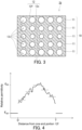
- a resin sheet 1b shown in FIG. 3 can also be provided.
- the resin sheet 1b is configured in the same manner as the resin sheet 1a, unless otherwise described.
- the components of the resin sheet 1b that are the same as or correspond to those of the resin sheet 1a are denoted by the same reference characters, and detailed descriptions of such components are omitted.
- the description given for the resin sheet 1a can apply to the resin sheet 1b, unless there is technical inconsistency.
- FIG. 4 shows a relation between the distance from the one end portion 12f in the thickness direction of the resin sheet 1b and the relative permittivity.
- the relative permittivity of the porous structure 10 varies, for example, in the thickness direction of the resin sheet 1b in a way that can be regarded as continuous.
- Such a porous structure 10 can be formed, for example, by foam injection molding. Alternatively, such a porous structure 10 may be formed by 3D printing.
- a radar system 100 can be provided using the resin sheets 1a and 1b.
- the radar system 100 includes a millimeter-wave radar 50 and the resin sheet 1a.
- the millimeter-wave radar 50 uses an FMCW.
- the resin sheet 1a allows transmission of a millimeter wave emitted from the millimeter-wave radar 50 through the resin sheet 1a.
- the resin sheet 1a can increase the transmittance of a wideband millimeter wave. Because of this, the radar system 100 tends to have a high accuracy of object sensing.
- the radar system 100 includes, for example, a housing 30.
- the housing 30 protects the millimeter-wave radar 50.
- the housing 30 is formed at least partly of the resin sheet 1a.
- the end portions 12 of the porous structure 10 are in contact with, for example, air.
- the average relative permittivity ⁇ A is maximum in the boundary portion 11b.
- the radar system 100 may include the resin sheet 1b instead of the resin sheet 1a.
- a transmission coefficient S 21 obtained by allowing a millimeter wave with a frequency of 60 to 80 GHz to be perpendicularly incident on each of resin sheets according to Examples and Comparative Examples was measured according to a horn antenna method defined in Japanese Industrial Standards (JIS) R 1679: 2007, and an average transmission loss T A S [dB] in the frequency range of 60 to 80 GHz was determined.
- a transmission coefficient S 21 obtained by allowing a millimeter wave with a frequency of 60 to 80 GHz to be perpendicularly incident on another resin substrate A to which no resin sheet was adhered was measured, and an average transmission loss T A R [dB] in the frequency range of 60 to 80 GHz was determined.
- a transmission loss improvement rate R of each resin sheet was determined by the following equation (2).
- Table 1 shows the results. It should be noted that the wavelength of a millimeter wave with a frequency of 60 Hz is 5 mm, and the wavelength of a millimeter wave with a frequency of 80 GHz is 3.75 mm.
- Cross-sections of each of the resin sheets according to Examples and Comparative Examples were measured by X-ray CT scanning using an X-ray CT scanner SKYSCAN 1272 manufactured by Bruker Corporation.
- the image analysis software Image J provided by the National Institutes of Health, USA, was used for reconstruction from cross-sectional images of the porous structure of each resin sheet, and a smallest pore diameter and a largest pore diameter were calculated.
- the average of the diameters of inscribed circles of pores in cross-sectional images taken between an interface and a position was determined as the smallest pore diameter, the interface being between one skin layer of the resin sheet and the porous structure, the position being 200 ⁇ m away from the interface in the thickness direction of the resin sheet toward the other skin layer of the resin sheet.
- the average of the diameters of inscribed circles of pores in cross-sectional images was determined as the largest pore diameter, the cross-sectional images being taken between a position being 250 ⁇ m away in the thickness direction of the resin sheet from a center defined in the thickness direction of the resin sheet toward one principal surface of the resin sheet and a position being 250 ⁇ m away in the thickness direction of the resin sheet from the center toward the other principal surface of the resin sheet.
- Table 1 shows the results.
- a relative permittivity of a resin forming the skeleton of the porous structure of each of the resin sheets according to Examples and Comparative Examples was measured at 10 GHz by a cavity resonance method. Table 1 shows the results.
- Each of the resin sheets according to Examples and Comparative Examples was measured by X-ray CT scanning using an X-ray CT scanner SKYSCAN 1272 manufactured by Bruker Corporation. On the basis of this measurement result, the porosity p in each of a plurality of 100- ⁇ m-thick layer portions forming the porous structure and arranged in the thickness direction of the resin sheet was determined.
- the difference ⁇ between average relative permittivities ⁇ L in each two adjacent layer portions of the plurality of layer portions was calculated. Table 1 shows the results. Table 1 also shows an average relative permittivity in two of the plurality of layer portions, the two layer portions forming the end portions of the porous structure.
- Thicknesses of the resin sheets according to Examples and Comparative Examples were measured using a micrometer. Table 1 shows the results.
- a mixture of supercritical nitrogen and polypropylene was molded by foaming and injection using a MuCell foaming injection molding apparatus to obtain a resin sheet according to Example 1.
- the resin sheet according to Example 1 had two principal surfaces each formed by a 350-pm-thick solid skin layer.
- a portion of the resin sheet according to Example 1 excluding the skin layers had a porous structure.
- the porous structure had a relative permittivity increasing in stages from the end portions toward a middle portion defined in the thickness direction of the resin sheet.
- the porous structure had a relative permittivity increasing in stages from one principal surface toward the other principal surface.
- FIG. 6 shows an example of an X-ray CT scan image of the resin sheet according to Example 1.
- a mixture of supercritical nitrogen and polypropylene was molded by foaming and injection using a MuCell foaming injection molding apparatus to obtain a resin sheet according to Example 2.
- the polypropylene had a relative permittivity of 2.2.
- the resin sheet according to Example 2 had two principal surfaces each formed by a 300-pm-thick solid skin layer.
- a portion of the resin sheet according to Example 2 excluding the skin layers had a porous structure.
- the porous structure had a relative permittivity increasing in stages from the end portions toward the middle portion defined in the thickness direction of the resin sheet.
- a mixture of supercritical nitrogen and polypropylene was molded by foaming and injection using a MuCell foaming injection molding apparatus to obtain a resin sheet according to Example 3.
- the resin sheet according to Example 3 had two principal surfaces each formed by a 150-pm-thick solid skin layer.
- a portion of the resin sheet according to Example 3 excluding the skin layers had a porous structure.
- the porous structure had a relative permittivity increasing in stages from the end portions toward the middle portion defined in the thickness direction of the resin sheet.
- a mixture of supercritical nitrogen and polyamide 6 was molded by foaming and injection using a MuCell foaming injection molding apparatus to obtain a resin sheet according to Example 4.
- the polyamide 6 had a relative permittivity of 4.9.
- the resin sheet according to Example 4 had two principal surfaces each formed by a 400-pm-thick solid skin layer.
- a portion of the resin sheet according to Example 4 excluding the skin layers had a porous structure.
- the porous structure had a relative permittivity increasing in stages from the end portions toward the middle portion defined in the thickness direction of the resin sheet.
- a mixture of supercritical carbon dioxide and polypropylene was molded by foaming and injection using a MuCell foaming injection molding apparatus to obtain a resin sheet according to Example 5.
- the resin sheet according to Example 5 had two principal surfaces each formed by a 510- ⁇ m-thick solid skin layer.
- a portion of the resin sheet according to Example 5 excluding the skin layers had a porous structure.
- the porous structure had a relative permittivity increasing in stages from the end portions toward the middle portion defined in the thickness direction of the resin sheet.
- a polypropylene resin ABSORTOMER EP1001 manufactured by Mitsui Chemicals, Inc. and a thermo-expandable microcapsule Matsumoto Microsphere FN-180S manufactured by Matsumoto Yushi-Seiyaku Co., Ltd. were mixed using Labo Plastomill at 100°C for 15 minutes to obtain a mixture, which was heat-pressed using a hot plate adjusted at 100°C to produce a 1000- ⁇ m-thick sheet having 50-square-millimeter principal surfaces.
- Labo Plastomill is a registered trademark of Toyo Seiki Seisaku-sho, Ltd. Then, the sheet was expanded at 150°C for 10 minutes to a thickness of 2000 ⁇ m to obtain a resin sheet according to Example 6.
- the thickness of the resin sheet was adjusted using a brass spacer having a dimension of 2000 ⁇ m.
- a portion of the resin sheet according to Example 6 excluding skin layers had a porous structure.
- the porous structure had a relative permittivity increasing in stages from the end portions toward the middle portion defined in the thickness direction of the resin sheet.
- a mixture of supercritical carbon dioxide and polypropylene was molded by foaming and injection using a MuCell foaming injection molding apparatus to obtain a resin sheet according to Example 7.
- the resin sheet according to Example 7 had two principal surfaces each formed by a 320-pm-thick solid skin layer.
- a portion of the resin sheet according to Example 7 excluding the skin layers had a porous structure.
- the porous structure had a relative permittivity increasing in stages from the end portions toward the middle portion defined in the thickness direction of the resin sheet.
- a homogeneous polyethylene foam was cut to a given size to obtain a resin sheet according to Comparative Example 1.
- the resin sheet according to Comparative Example 1 had a relative permittivity being constant from one principal surface to the other principal surface.
- the resin sheets according to Examples had an improvement rate R of 35% or more.
- the resin sheet according to Comparative Example 1 had an improvement rate R of less than 35%.
Landscapes
- Chemical & Material Sciences (AREA)
- Engineering & Computer Science (AREA)
- Medicinal Chemistry (AREA)
- Organic Chemistry (AREA)
- Materials Engineering (AREA)
- Health & Medical Sciences (AREA)
- Chemical Kinetics & Catalysis (AREA)
- Polymers & Plastics (AREA)
- Radar, Positioning & Navigation (AREA)
- Remote Sensing (AREA)
- Manufacturing & Machinery (AREA)
- Computer Networks & Wireless Communication (AREA)
- Physics & Mathematics (AREA)
- General Physics & Mathematics (AREA)
- Computer Security & Cryptography (AREA)
- Manufacture Of Porous Articles, And Recovery And Treatment Of Waste Products (AREA)
- Laminated Bodies (AREA)
- Details Of Aerials (AREA)
- Radar Systems Or Details Thereof (AREA)
Abstract
Description
- The present invention relates to a resin sheet and a radar system.
- Radars have been used to detect objects. Adjusting members allowing transmission of radio waves from radars therethrough have been known.
- For example, a system including a radar sensor and an adjusting member is described in Patent Literature 1. This system is to be mounted on a motor vehicle so that the adjusting member will allow transmission of a radio wave from the radar sensor therethrough. The adjusting member includes at least one layer that reflects a portion of the radio wave. The adjusting member includes an additional layer configured based on a thickness and a permittivity suitable for reducing reflection of the radio wave. The adjusting member is a bumper. The radar sensor is, for example, a 77-GHz radar.
- Patent Literature 1:
US 2015/0109162 A1 - In the technique described in Patent Literature 1, the adjusting member includes the additional layer configured to reduce reflection of the radio wave. However, in Patent Literature 1, adjustment of transmission of a millimeter wave from a millimeter-wave radar using a frequency-modulated continuous wave (FMCW) is not taken into consideration.
- Therefore, the present invention provides a resin sheet that is advantageous in view of adjusting transmission of a millimeter wave from a millimeter-wave radar using an FMCW.
- The present invention provides a resin sheet including:
- a porous structure configured to adjust transmission of a millimeter wave, wherein
- the porous structure has a relative permittivity varying in a thickness direction of the resin sheet such that a difference between average relative permittivities in two adjacent layer portions is a predetermined value or less, the layer portions each having a particular thickness smaller than a wavelength of the millimeter wave,
- the porous structure includes a boundary portion being one of the layer portions, the boundary portion having a maximum or minimum average relative permittivity, and
- the relative permittivity increases or decreases in stages from end portions of the porous structure toward the boundary portion, the end portions being defined in the thickness direction of the resin sheet.
- The present invention also provides a radar system including:
- a millimeter-wave radar using a frequency-modulated continuous wave; and
- the above resin sheet allowing transmission of a millimeter wave emitted from the millimeter-wave radar through the resin sheet.
- The above resin sheet is advantageous in view of adjusting transmission of a millimeter wave from a millimeter-wave radar using an FMCW. With the use of the above radar system, transmission of a millimeter wave from a millimeter-wave radar using an FMCW can be adjusted to a desired state.
-
-
FIG. 1 is a cross-sectional view showing an example of the resin sheet according to the present invention. -
FIG. 2 is a graph showing a varying relative permittivity of a porous structure. -
FIG. 3 is a cross-sectional view showing another example of the resin sheet according to the present invention. -
FIG. 4 is a graph showing a varying relative permittivity of a porous structure. -
FIG. 5 shows an example of the radar system according to the present invention. -
FIG. 6 is an X-ray CT image showing an example of a cross-section of a resin sheet according to Example 1. - It is conceivable to use, for sensing a given object, a millimeter-wave radar using an FMCW. In this case, a given structure such as a housing may be needed to be disposed in a transmission-reception path of a millimeter wave to protect the millimeter-wave radar. It is thought that widening a frequency range of a millimeter wave used for sensing an object using the above millimeter-wave radar is advantageous in improving the accuracy of object sensing. Therefore, the present inventors conducted intensive studies to invent a sheet capable of being included in a structure disposed in a transmission-reception path to protect a millimeter-wave radar, the sheet being capable of improving transmission of a millimeter wave in a wide frequency range. Through much trial and error, the present inventors have newly found that a resin sheet having a given porous structure is advantageous in enhancing transmission of a millimeter wave in a wide frequency range and have completed the present invention.
- Hereinafter, embodiments of the present invention will be described with reference to the drawings. The following description describes examples of the present invention, and the present invention is not limited to the following embodiments.
- As shown in
FIG. 1 , aresin sheet 1a includes aporous structure 10. Theporous structure 10 is configured to adjust transmission of a millimeter wave. As shown inFIG. 2 , theporous structure 10 has a relative permittivity varying in a thickness direction of theresin sheet 1a such that a difference Δε between average relative permittivities εL in twoadjacent layer portions 11 is a predetermined value Ve or less, thelayer portions 11 each having a particular thickness tL smaller than a wavelength of the millimeter wave. Additionally, theporous structure 10 includes aboundary portion 11b. Theboundary portion 11b is one of thelayer portions 11 and has a maximum average relative permittivity εA. In theporous structure 10, the relative permittivity increases in stages fromend portions 12 of theporous structure 10 toward theboundary portion 11b, theend portions 12 being defined in the thickness direction of theresin sheet 1a. With such structural features, in theporous structure 10, a relative permittivity variation rapid enough to affect millimeter-wave propagation can be prevented at an interface between theporous structure 10 and another substance such as air and inside theporous structure 10. Consequently, theresin sheet 1a can reduce reflection of the millimeter wave and can have an increased millimeter-wave transmittance. In particular, theresin sheet 1a can have an increased transmittance of a wideband millimeter wave from a millimeter-wave radar using an FMCW. With theresin sheet 1a, a transmission loss [dB] of a perpendicularly incident millimeter wave in a bandwidth of 60 to 80 GHz can be reduced by, for example, 35% or more, desirably 40% or more, more desirably 45% or more, even more desirably 50% or more, compared to the case without theresin sheet 1a. - The
boundary portion 11b may be one of thelayer portions 11 and has a minimum average relative permittivity εA. In this case, in theporous structure 10, the relative permittivity decreases in stages from theend portions 12 of theporous structure 10 toward theboundary portion 11b, theend portions 12 being defined in the thickness direction of theresin sheet 1a. With such structural features, a relative permittivity variation rapid enough to affect millimeter-wave propagation can be prevented even when theend portions 12 of theresin sheet 1a are in contact with a substance having a relatively high relative permittivity. Consequently, theresin sheet 1a can reduce reflection of a millimeter wave and can have an increased millimeter-wave transmittance. - Typically, the entire
porous structure 10 satisfies the requirement that the difference Δε between average relative permittivities in each twoadjacent layer portions 11 is the predetermined value Ve or less. - As shown in
FIG. 1 , theend portions 12 of theporous structure 10 include oneend portion 12f and theother end portion 12s. InFIG. 2 , a distance T from the oneend portion 12f corresponds to the thickness of theporous structure 10. InFIG. 2 , theend portions 12 of theporous structure 10 are assumed to be in contact with air. InFIG. 2 , εair represents a relative permittivity of air, and εM represents the largest value of the average relative permittivities εL. A boundary between each twolayer portions 11 may be real or imaginary. - For example, the relative permittivity of the
porous structure 10 can be adjusted as described above by varying the porosity in stages in the thickness direction of theporous structure 10. - An average relative permittivity εL in each
layer portion 11 of theporous structure 10 can be determined, for example, by the following equation (1). In the equation (1), εK is a relative permittivity of the material of a skeleton of theporous structure 10, εair is the relative permittivity of air, and p is a porosity (0 < p < 1) in thelayer portion 11. The porosity p in eachlayer portion 11 can be determined, for example, based on the X-ray CT measurement result for theporous structure 10. The relative permittivity of the material of the skeleton of theporous structure 10 is, for example, a relative permittivity measured at 10 GHz by a cavity resonance method.
- The particular thickness tL is not limited to a particular value as long as the particular thickness tL is smaller than the wavelength of a millimeter wave. The particular thickness tL is, for example, 100 µm. The predetermined value Ve is not limited to a particular value as long as the
resin sheet 1a can have an increased transmittance of a millimeter wave. The predetermined value Ve is, for example, 0.3. The predetermined value Ve is desirably 0.25. - The largest value of Δε in the
porous structure 10 is not limited to a particular value. The largest value of Δε is, for example, 0.1 or more and 0.3 or less. This prevents an increase of the thickness of theporous structure 10 when theporous structure 10 is formed such that the relative permittivity increases or decreases in stages in the thickness direction of theresin sheet 1a from theend portions 12 of theporous structure 10 toward theboundary portion 11b. - The thickness of the
porous structure 10 is not limited to a particular value as long as theresin sheet 1a can have an increased transmittance of a millimeter wave. Theporous structure 10 has a thickness of, for example, 1 mm or more. In this case, theresin sheet 1a can have an increased transmittance of a millimeter wave and can protect a millimeter-wave radar as appropriate. - The thickness of the
porous structure 10 is desirably 2 mm or more, and more desirably 3 mm or more. The thickness of theporous structure 10 is, for example, 10 mm or less. This makes it easy to reduce the weight of theresin sheet 1a. - The relative permittivity of the
porous structure 10 is not limited to a particular value as long as Δε is 0.3 or less and the relative permittivity increases or decreases in stages from theend portions 12 of theporous structure 10 toward theboundary portion 11b. Theporous structure 10 has a relative permittivity of, for example, 1.01 or more and 4.99 or less. In this case, theresin sheet 1a can have an increased transmittance of a millimeter wave more reliably. - The relative permittivity εK of the material of the skeleton of the
porous structure 10 is not limited to a particular value as long as theresin sheet 1a can have an increased transmittance of a millimeter wave. The relative permittivity εK is, for example, 2.2 to 5.0. - The material of the skeleton of the
porous structure 10 is not limited to a particular material as long as theresin sheet 1a can have an increased transmittance of a millimeter wave. Examples of the material include polyethylene, polypropylene, polystyrene, polyester, polyamide, polyvinyl chloride, polyvinylidene chloride, polybutene, polyacetal, polyphenylene oxide, polymethylmethacrylate, polysulfone, polyethersulfone, polyetherketone, polyetheretherketone, polyamide-imide, polycarbonate, polyarylate, polyimide, fluorine resin, ethylene-propylene resin, ethylene-ethylacrylate, epoxy resin, urethane resin, imide resin, acrylic resin, and norbornene resin. The skeleton of theporous structure 10 may include only one resin material or may include a plurality of resin materials. The skeleton of theporous structure 10 may be formed of a polymer alloy or may be formed of a composite material of a resin matrix and a filler. - The relative permittivity in each of the
end portions 12 of theporous structure 10 is not limited to a particular value as long as Δε is 0.3 or less and the relative permittivity increases or decreases in stages from theend portions 12 of theporous structure 10 toward theboundary portion 11b. When the relative permittivity increases in stages from theend portions 12 of theporous structure 10 toward theboundary portion 11b, the relative permittivity in each of theend portions 12 of theporous structure 10 is, for example, 1.8 or less. In this case, theresin sheet 1a can reduce reflection of a millimeter wave and can have an increased millimeter-wave transmittance, for example, when theresin sheet 1a is used such that theend portions 12 of theporous structure 10 is in contact a substance, such as air, having a relatively low relative permittivity. The relative permittivity in each of theend portions 12 of theporous structure 10 may be 1.75 or less, 1.7 or less, or 1.65 or less. - As shown in
FIG. 1 , theporous structure 10 has pores 13. The pore diameter of eachpore 13 is not limited to a particular value as long as Δε is 0.3 or less and the relative permittivity increases or decreases in stages from theend portions 12 of theporous structure 10 toward theboundary portion 11b. Eachpore 13 has a pore diameter equal to or less than 10% of the wavelength of a millimeter wave. In this case, theresin sheet 1a can more reliably reduce reflection of a millimeter wave and can have an increased millimeter-wave transmittance. The pore diameter of eachpore 13 refers to, for example, the maximum diameter thereof observed in a scanning electron microscope (SEM) image of a cross-section of theporous structure 10. The pore diameter of eachpore 13 may be determined based on the X-ray CT measurement result for theporous structure 10. - The pore diameter of each
pore 13 is desirably equal to or less than 7% of the wavelength of a millimeter wave. - A ratio of the number of
pores 13 having a pore diameter equal to or less than 10% of the wavelength of a millimeter wave to the number ofpores 13 included in theporous structure 10 is, for example, 80% or more, desirably 85% or more, more desirably 90% or more, even more desirably 95% or more, and particularly desirably 98% or more. Theporous structure 10 may have, as pores, only thepores 13 each having a pore diameter equal to or less than 10% of the wavelength of a millimeter wave. - The
porous structure 10 has, for example, thepores 13 each having a pore diameter of 20 to 500 µm. In this case, theresin sheet 1a can more reliably reduce reflection of a millimeter wave and can have an increased millimeter-wave transmittance. The pore diameter of eachpore 13 may be 450 µm or less, 400 µm or less, or 350 µm or less. Theporous structure 10 may have, for example, thepores 13 each having a pore diameter of 20 to 550 µm. - A ratio of the number of
pores 13 having a pore diameter of 20 to 500 µm to the number ofpores 13 included in theporous structure 10 is, for example, 80% or more, desirably 85% or more, more desirably 90% or more, even more desirably 95% or more, and particularly desirably 98% or more. Theporous structure 10 may have, as pores, only thepores 13 each having a pore diameter of 20 to 500 µm. Theporous structure 10 may have, as pores, only thepores 13 each having a pore diameter of 20 to 550 µm. - As shown in
FIG. 2 , the relative permittivity of theporous structure 10 varies, for example, in the thickness direction of theresin sheet 1a in a way that can be regarded as discrete. Such aporous structure 10 can be formed, for example, by laminating a plurality of homogeneous porous layers having different porosities. Alternatively, such aporous structure 10 may be formed by 3D printing. - The
resin sheet 1a may include, for example, a skin layer (not illustrated), and theresin sheet 1a may have one surface formed by the skin layer or may have two surfaces each formed by the skin layer. The skin layer has a thickness, for example, equal to or less than 10% of the wavelength of a millimeter wave. The skin layer having a thickness equal to or less than 10% of the wavelength of a millimeter wave is likely to have a reduced effect on transmission of a millimeter wave even when the skin layer has a relatively high relative permittivity. - The skin layer 20 is typically a solid layer. The thickness of the skin layer 20 is, for example, 550 µm or less, desirably 500 µm or less, more desirably 450 µm or less, even more desirably 400 µm or less.
- A
resin sheet 1b shown inFIG. 3 can also be provided. Theresin sheet 1b is configured in the same manner as theresin sheet 1a, unless otherwise described. The components of theresin sheet 1b that are the same as or correspond to those of theresin sheet 1a are denoted by the same reference characters, and detailed descriptions of such components are omitted. The description given for theresin sheet 1a can apply to theresin sheet 1b, unless there is technical inconsistency. -
FIG. 4 shows a relation between the distance from the oneend portion 12f in the thickness direction of theresin sheet 1b and the relative permittivity. In theresin sheet 1b, the relative permittivity of theporous structure 10 varies, for example, in the thickness direction of theresin sheet 1b in a way that can be regarded as continuous. Such aporous structure 10 can be formed, for example, by foam injection molding.
Alternatively, such aporous structure 10 may be formed by 3D printing. - For example, a
radar system 100 can be provided using theresin sheets FIG. 5 , theradar system 100 includes a millimeter-wave radar 50 and theresin sheet 1a. The millimeter-wave radar 50 uses an FMCW. Theresin sheet 1a allows transmission of a millimeter wave emitted from the millimeter-wave radar 50 through theresin sheet 1a. As described above, theresin sheet 1a can increase the transmittance of a wideband millimeter wave. Because of this, theradar system 100 tends to have a high accuracy of object sensing. - As shown in
FIG. 5 , theradar system 100 includes, for example, ahousing 30. Thehousing 30 protects the millimeter-wave radar 50. For example, thehousing 30 is formed at least partly of theresin sheet 1a. - As shown in
FIG. 5 , in theradar system 100, theend portions 12 of theporous structure 10 are in contact with, for example, air. In this case, the average relative permittivity εA is maximum in theboundary portion 11b. - The
radar system 100 may include theresin sheet 1b instead of theresin sheet 1a. - The present invention will be described in more detail by examples. The present invention is not limited to the examples given below. First, methods for evaluation of examples will be described.
- A transmission coefficient S21 obtained by allowing a millimeter wave with a frequency of 60 to 80 GHz to be perpendicularly incident on each of resin sheets according to Examples and Comparative Examples was measured according to a horn antenna method defined in Japanese Industrial Standards (JIS) R 1679: 2007, and an average transmission loss TA S [dB] in the frequency range of 60 to 80 GHz was determined. Moreover, a transmission coefficient S21 obtained by allowing a millimeter wave with a frequency of 60 to 80 GHz to be perpendicularly incident on another resin substrate A to which no resin sheet was adhered was measured, and an average transmission loss TA R [dB] in the frequency range of 60 to 80 GHz was determined. A transmission loss improvement rate R of each resin sheet was determined by the following equation (2). Table 1 shows the results. It should be noted that the wavelength of a millimeter wave with a frequency of 60 Hz is 5 mm, and the wavelength of a millimeter wave with a frequency of 80 GHz is 3.75 mm. As a measurement apparatus was used a millimeterwave-microwave transmission loss measurement system, Model No. RTS01, manufactured by KEYCOM Corporation or a 30 mmΦ transmission loss-return loss measurement system for millimeter waves, Model No. RTS06, manufactured by KEYCOM Corporation.

- Cross-sections of each of the resin sheets according to Examples and Comparative Examples were measured by X-ray CT scanning using an X-ray CT scanner SKYSCAN 1272 manufactured by Bruker Corporation. The image analysis software Image J provided by the National Institutes of Health, USA, was used for reconstruction from cross-sectional images of the porous structure of each resin sheet, and a smallest pore diameter and a largest pore diameter were calculated. The average of the diameters of inscribed circles of pores in cross-sectional images taken between an interface and a position was determined as the smallest pore diameter, the interface being between one skin layer of the resin sheet and the porous structure, the position being 200 µm away from the interface in the thickness direction of the resin sheet toward the other skin layer of the resin sheet. On the other hand, the average of the diameters of inscribed circles of pores in cross-sectional images was determined as the largest pore diameter, the cross-sectional images being taken between a position being 250 µm away in the thickness direction of the resin sheet from a center defined in the thickness direction of the resin sheet toward one principal surface of the resin sheet and a position being 250 µm away in the thickness direction of the resin sheet from the center toward the other principal surface of the resin sheet. Table 1 shows the results.
- A relative permittivity of a resin forming the skeleton of the porous structure of each of the resin sheets according to Examples and Comparative Examples was measured at 10 GHz by a cavity resonance method. Table 1 shows the results. Each of the resin sheets according to Examples and Comparative Examples was measured by X-ray CT scanning using an X-ray CT scanner SKYSCAN 1272 manufactured by Bruker Corporation. On the basis of this measurement result, the porosity p in each of a plurality of 100-µm-thick layer portions forming the porous structure and arranged in the thickness direction of the resin sheet was determined. The average relative permittivity εL of each of the layer portions was calculated by the above equation (1) from the thus-determined porosity p, the relative permittivity εK of the resin measured as described above, and the relative permittivity εair (= 1.0) of air. The difference Δε between average relative permittivities εL in each two adjacent layer portions of the plurality of layer portions was calculated. Table 1 shows the results. Table 1 also shows an average relative permittivity in two of the plurality of layer portions, the two layer portions forming the end portions of the porous structure.
- Thicknesses of the resin sheets according to Examples and Comparative Examples were measured using a micrometer. Table 1 shows the results.
- A mixture of supercritical nitrogen and polypropylene was molded by foaming and injection using a MuCell foaming injection molding apparatus to obtain a resin sheet according to Example 1. The resin sheet according to Example 1 had two principal surfaces each formed by a 350-pm-thick solid skin layer. A portion of the resin sheet according to Example 1 excluding the skin layers had a porous structure. The porous structure had a relative permittivity increasing in stages from the end portions toward a middle portion defined in the thickness direction of the resin sheet. The porous structure had a relative permittivity increasing in stages from one principal surface toward the other principal surface.
FIG. 6 shows an example of an X-ray CT scan image of the resin sheet according to Example 1. - A mixture of supercritical nitrogen and polypropylene was molded by foaming and injection using a MuCell foaming injection molding apparatus to obtain a resin sheet according to Example 2. The polypropylene had a relative permittivity of 2.2. The resin sheet according to Example 2 had two principal surfaces each formed by a 300-pm-thick solid skin layer. A portion of the resin sheet according to Example 2 excluding the skin layers had a porous structure. The porous structure had a relative permittivity increasing in stages from the end portions toward the middle portion defined in the thickness direction of the resin sheet.
- A mixture of supercritical nitrogen and polypropylene was molded by foaming and injection using a MuCell foaming injection molding apparatus to obtain a resin sheet according to Example 3. The resin sheet according to Example 3 had two principal surfaces each formed by a 150-pm-thick solid skin layer. A portion of the resin sheet according to Example 3 excluding the skin layers had a porous structure. The porous structure had a relative permittivity increasing in stages from the end portions toward the middle portion defined in the thickness direction of the resin sheet.
- A mixture of supercritical nitrogen and polyamide 6 was molded by foaming and injection using a MuCell foaming injection molding apparatus to obtain a resin sheet according to Example 4. The polyamide 6 had a relative permittivity of 4.9. The resin sheet according to Example 4 had two principal surfaces each formed by a 400-pm-thick solid skin layer. A portion of the resin sheet according to Example 4 excluding the skin layers had a porous structure. The porous structure had a relative permittivity increasing in stages from the end portions toward the middle portion defined in the thickness direction of the resin sheet.
- A mixture of supercritical carbon dioxide and polypropylene was molded by foaming and injection using a MuCell foaming injection molding apparatus to obtain a resin sheet according to Example 5. The resin sheet according to Example 5 had two principal surfaces each formed by a 510-µm-thick solid skin layer. A portion of the resin sheet according to Example 5 excluding the skin layers had a porous structure. The porous structure had a relative permittivity increasing in stages from the end portions toward the middle portion defined in the thickness direction of the resin sheet.
- A polypropylene resin ABSORTOMER EP1001 manufactured by Mitsui Chemicals, Inc. and a thermo-expandable microcapsule Matsumoto Microsphere FN-180S manufactured by Matsumoto Yushi-Seiyaku Co., Ltd. were mixed using Labo Plastomill at 100°C for 15 minutes to obtain a mixture, which was heat-pressed using a hot plate adjusted at 100°C to produce a 1000-µm-thick sheet having 50-square-millimeter principal surfaces. Labo Plastomill is a registered trademark of Toyo Seiki Seisaku-sho, Ltd. Then, the sheet was expanded at 150°C for 10 minutes to a thickness of 2000 µm to obtain a resin sheet according to Example 6. The thickness of the resin sheet was adjusted using a brass spacer having a dimension of 2000 µm. A portion of the resin sheet according to Example 6 excluding skin layers had a porous structure. The porous structure had a relative permittivity increasing in stages from the end portions toward the middle portion defined in the thickness direction of the resin sheet.
- A mixture of supercritical carbon dioxide and polypropylene was molded by foaming and injection using a MuCell foaming injection molding apparatus to obtain a resin sheet according to Example 7. The resin sheet according to Example 7 had two principal surfaces each formed by a 320-pm-thick solid skin layer. A portion of the resin sheet according to Example 7 excluding the skin layers had a porous structure. The porous structure had a relative permittivity increasing in stages from the end portions toward the middle portion defined in the thickness direction of the resin sheet.
- A homogeneous polyethylene foam was cut to a given size to obtain a resin sheet according to Comparative Example 1. The resin sheet according to Comparative Example 1 had a relative permittivity being constant from one principal surface to the other principal surface.
- As shown in Table 1, the resin sheets according to Examples had an improvement rate R of 35% or more. On the other hand, the resin sheet according to Comparative Example 1 had an improvement rate R of less than 35%. These indicate that it is advantageous for the porous structure of the resin sheet to have a relative permittivity increasing in stages from the end portions toward the middle portion defined in the thickness direction of the resin sheet, the relative permittivity increasing such that Δε is 0.3 or less.
[Table 1] Ex. 1 Ex. 2 Ex. 3 Ex. 4 Ex. 5 Ex. 6 Ex. 7 Comp. Ex. 1 Difference Δε between average relative permittivities 0.09 to 0.30 0.01 to 0.30 0.01 to 0.30 0.01 to 0.30 0.01 to 0.30 0.01 to 0.12 0.01 to 0.09 - Pore diameters [µm] of pores 20 to 300 30 to 150 30 to 200 30 to 150 20 to 300 40 to 80 450 to 550 300 Thickness [mm] 10 6 3 10 2 2 3 1 Relative permittivity of resin in porous structure - 2.2 2.2 4.9 2.2 2.6 2.2 2.2 Thickness [µm] of skin layer 350 300 150 400 510 100 320 100 Average relative permittivity in each end portion of porous structure 1.19 1.48 1.60 1.62 1.7 1.8 1.6 1.18 Improvement rate R [%] 89 85 82 85 37 43 41 30
Claims (13)
- A resin sheet comprising:a porous structure configured to adjust transmission of a millimeter wave, whereinthe porous structure has a relative permittivity varying in a thickness direction of the resin sheet such that a difference between average relative permittivities in two adjacent layer portions is a predetermined value or less, the layer portions each having a particular thickness smaller than a wavelength of the millimeter wave,the porous structure includes a boundary portion being one of the layer portions, the boundary portion having a maximum or minimum average relative permittivity, andthe relative permittivity increases or decreases in stages from end portions of the porous structure toward the boundary portion, the end portions being defined in the thickness direction of the resin sheet.
- The resin sheet according to claim 1, whereinthe average relative permittivity is maximum in the boundary portion, andthe relative permittivity increases in stages from the end portions of the porous structure toward the boundary portion, the end portions being defined in the thickness direction of the resin sheet.
- The resin sheet according to claim 2, wherein the relative permittivity is 1.8 or less at the end portions.
- The resin sheet according to claim 2, wherein the relative permittivity is 1.75 or less at the end portions.
- The resin sheet according to any one of claims 1 to 4, wherein the particular thickness is 100 µm and the predetermined value is 0.3.
- The resin sheet according to any one of claims 1 to 5, wherein the porous structure has a thickness of 1 mm or more.
- The resin sheet according to any one of claims 1 to 6, wherein the porous structure has a relative permittivity of 1.01 or more and 4.99 or less.
- The resin sheet according to any one of claims 1 to 7, wherein the porous structure has pores each having a pore diameter equal to or less than 10% of the wavelength of the millimeter wave.
- The resin sheet according to any one of claims 1 to 8, wherein the porous structure has pores each having a pore diameter of 20 to 550 µm.
- The resin sheet according to any one of claims 1 to 9, wherein the porous structure has pores each having a pore diameter of 20 to 500 µm.
- A radar system comprising:a millimeter-wave radar using a frequency-modulated continuous wave; andthe resin sheet according to any one of claims 1 to 10 allowing transmission of a millimeter wave emitted from the millimeter-wave radar through the resin sheet.
- The radar system according to claim 11, further comprising a housing formed at least partly of the resin sheet.
- The radar system according to claim 11 or 12, wherein the end portions of the porous structure in the resin sheet are in contact with air.
Applications Claiming Priority (2)
| Application Number | Priority Date | Filing Date | Title |
|---|---|---|---|
| JP2020064891 | 2020-03-31 | ||
| PCT/JP2021/008001 WO2021199857A1 (en) | 2020-03-31 | 2021-03-02 | Resin sheet and radar system |
Publications (1)
| Publication Number | Publication Date |
|---|---|
| EP4130780A1 true EP4130780A1 (en) | 2023-02-08 |
Family
ID=77930282
Family Applications (1)
| Application Number | Title | Priority Date | Filing Date |
|---|---|---|---|
| EP21781705.5A Withdrawn EP4130780A1 (en) | 2020-03-31 | 2021-03-02 | Resin sheet and radar system |
Country Status (6)
| Country | Link |
|---|---|
| US (1) | US20230129032A1 (en) |
| EP (1) | EP4130780A1 (en) |
| JP (1) | JP2021162576A (en) |
| CN (1) | CN115210597A (en) |
| TW (1) | TW202146548A (en) |
| WO (1) | WO2021199857A1 (en) |
Family Cites Families (10)
| Publication number | Priority date | Publication date | Assignee | Title |
|---|---|---|---|---|
| JPS54107655A (en) * | 1978-02-13 | 1979-08-23 | Nippon Telegr & Teleph Corp <Ntt> | Radome for antenna installed indoor |
| US4629563B1 (en) * | 1980-03-14 | 1997-06-03 | Memtec North America | Asymmetric membranes |
| JPS63316904A (en) * | 1987-06-19 | 1988-12-26 | Sumitomo Electric Ind Ltd | Membrane material for metal space frame radome |
| JPH10150316A (en) * | 1996-11-20 | 1998-06-02 | Furukawa Electric Co Ltd:The | Planar antenna device |
| JP2003078325A (en) * | 2001-08-30 | 2003-03-14 | Hitachi Cable Ltd | Antenna cover and antenna |
| WO2011033935A1 (en) * | 2009-09-17 | 2011-03-24 | 三菱電機株式会社 | Radome equipment |
| DE102013221055A1 (en) | 2013-10-17 | 2015-04-23 | Robert Bosch Gmbh | Combination of radar sensor and cowling for a motor vehicle |
| US20170008251A1 (en) * | 2015-07-08 | 2017-01-12 | Raytheon Company | High performance plastic radome |
| WO2017104715A1 (en) * | 2015-12-16 | 2017-06-22 | テクノポリマー株式会社 | Resin component disposed in path of beam emitted by radar equipment, radome, and radar equipment |
| JP7159049B2 (en) * | 2016-09-08 | 2022-10-24 | Nok株式会社 | Cover for millimeter wave radar |
-
2021
- 2021-03-02 JP JP2021032915A patent/JP2021162576A/en active Pending
- 2021-03-02 US US17/915,273 patent/US20230129032A1/en not_active Abandoned
- 2021-03-02 EP EP21781705.5A patent/EP4130780A1/en not_active Withdrawn
- 2021-03-02 WO PCT/JP2021/008001 patent/WO2021199857A1/en not_active Ceased
- 2021-03-02 CN CN202180018205.0A patent/CN115210597A/en active Pending
- 2021-03-26 TW TW110111077A patent/TW202146548A/en unknown
Also Published As
| Publication number | Publication date |
|---|---|
| CN115210597A (en) | 2022-10-18 |
| US20230129032A1 (en) | 2023-04-27 |
| JP2021162576A (en) | 2021-10-11 |
| WO2021199857A1 (en) | 2021-10-07 |
| TW202146548A (en) | 2021-12-16 |
Similar Documents
| Publication | Publication Date | Title |
|---|---|---|
| EP4130117A1 (en) | Resin sheet, layered body, and radar system | |
| US20200295452A1 (en) | Millimeter-wave radar cover | |
| US9761933B2 (en) | Millimeter wave antenna and radar apparatus for vehicle | |
| US10048355B2 (en) | Method and radar apparatus for detecting target object | |
| EP1635187B1 (en) | Millimeter wave radar with side-lobe absorbing radome | |
| EP3569990B1 (en) | Attachment assembly for a radar fill level measuring device | |
| Vohra et al. | K-and W-band free-space characterizations of highly conductive radar absorbing materials | |
| US12216225B2 (en) | Facia supporting an ultra-wide radar field-of-view | |
| EP2035790A1 (en) | Apparatus for determining and/or monitoring the level of a medium | |
| EP4130780A1 (en) | Resin sheet and radar system | |
| US7999738B2 (en) | Systems and methods for tracking a remote source and orientation control | |
| Kim et al. | Impact damage and antenna performance of conformal load-bearing antenna structures | |
| US20260103574A1 (en) | Plate-shaped composite material | |
| DE102010042443B4 (en) | Device and method for non-destructive measurement of the bending stiffness of fuel cells | |
| RU2500704C2 (en) | Electromagnetic wave absorber and radar absorbent material for production thereof | |
| DE102018101798B4 (en) | Horn antenna for a radar gauge and radar gauge | |
| DE102009027725B4 (en) | Headrest with microwave sensor | |
| KR102622965B1 (en) | Sandwich-shaped structure for absorbing electromagnetic wave in the uhf-band | |
| JP2009047633A (en) | Radar equipment | |
| She et al. | Autofocus for ISAR imaging using higher order statistics | |
| Futatsumori et al. | Ground reflection power measurements of thin high-voltage power lines using 76 GHz helicopter forward-looking low-transmitting power millimeter-wave radar | |
| GB2607394A (en) | Polarization direction measuring device, method of acquiring intensity ratio tables, polarization direction measuring method, and computer-readable storage me | |
| US20250228465A1 (en) | Biological information detection device and vehicle including same | |
| US20240266719A1 (en) | Satellite platform having improved characteristics in respect of electromagnetic decoupling between radiating elements and corresponding construction process | |
| EP1891420A1 (en) | Testing of components or semifinished products with an expanded metallic layer |
Legal Events
| Date | Code | Title | Description |
|---|---|---|---|
| STAA | Information on the status of an ep patent application or granted ep patent |
Free format text: STATUS: THE INTERNATIONAL PUBLICATION HAS BEEN MADE |
|
| PUAI | Public reference made under article 153(3) epc to a published international application that has entered the european phase |
Free format text: ORIGINAL CODE: 0009012 |
|
| STAA | Information on the status of an ep patent application or granted ep patent |
Free format text: STATUS: REQUEST FOR EXAMINATION WAS MADE |
|
| 17P | Request for examination filed |
Effective date: 20221017 |
|
| AK | Designated contracting states |
Kind code of ref document: A1 Designated state(s): AL AT BE BG CH CY CZ DE DK EE ES FI FR GB GR HR HU IE IS IT LI LT LU LV MC MK MT NL NO PL PT RO RS SE SI SK SM TR |
|
| STAA | Information on the status of an ep patent application or granted ep patent |
Free format text: STATUS: THE APPLICATION HAS BEEN WITHDRAWN |
|
| 18W | Application withdrawn |
Effective date: 20230208 |