EP4130756B1 - A snap-on current sensor design - Google Patents
A snap-on current sensor design Download PDFInfo
- Publication number
- EP4130756B1 EP4130756B1 EP22185310.4A EP22185310A EP4130756B1 EP 4130756 B1 EP4130756 B1 EP 4130756B1 EP 22185310 A EP22185310 A EP 22185310A EP 4130756 B1 EP4130756 B1 EP 4130756B1
- Authority
- EP
- European Patent Office
- Prior art keywords
- snap
- insert
- assembly
- housing
- extension
- Prior art date
- Legal status (The legal status is an assumption and is not a legal conclusion. Google has not performed a legal analysis and makes no representation as to the accuracy of the status listed.)
- Active
Links
Images



Classifications
-
- G—PHYSICS
- G01—MEASURING; TESTING
- G01R—MEASURING ELECTRIC VARIABLES; MEASURING MAGNETIC VARIABLES
- G01R1/00—Details of instruments or arrangements of the types included in groups G01R5/00 - G01R13/00 and G01R31/00
- G01R1/02—General constructional details
- G01R1/04—Housings; Supporting members; Arrangements of terminals
-
- G—PHYSICS
- G01—MEASURING; TESTING
- G01R—MEASURING ELECTRIC VARIABLES; MEASURING MAGNETIC VARIABLES
- G01R19/00—Arrangements for measuring currents or voltages or for indicating presence or sign thereof
- G01R19/0092—Measuring current only
-
- G—PHYSICS
- G01—MEASURING; TESTING
- G01R—MEASURING ELECTRIC VARIABLES; MEASURING MAGNETIC VARIABLES
- G01R33/00—Arrangements or instruments for measuring magnetic variables
- G01R33/0047—Housings or packaging of magnetic sensors ; Holders
-
- G—PHYSICS
- G01—MEASURING; TESTING
- G01R—MEASURING ELECTRIC VARIABLES; MEASURING MAGNETIC VARIABLES
- G01R15/00—Details of measuring arrangements of the types provided for in groups G01R17/00 - G01R29/00, G01R33/00 - G01R33/26 or G01R35/00
- G01R15/14—Adaptations providing voltage or current isolation, e.g. for high-voltage or high-current networks
- G01R15/20—Adaptations providing voltage or current isolation, e.g. for high-voltage or high-current networks using galvano-magnetic devices, e.g. Hall-effect devices, i.e. measuring a magnetic field via the interaction between a current and a magnetic field, e.g. magneto resistive or Hall effect devices
-
- G—PHYSICS
- G01—MEASURING; TESTING
- G01R—MEASURING ELECTRIC VARIABLES; MEASURING MAGNETIC VARIABLES
- G01R15/00—Details of measuring arrangements of the types provided for in groups G01R17/00 - G01R29/00, G01R33/00 - G01R33/26 or G01R35/00
- G01R15/14—Adaptations providing voltage or current isolation, e.g. for high-voltage or high-current networks
- G01R15/20—Adaptations providing voltage or current isolation, e.g. for high-voltage or high-current networks using galvano-magnetic devices, e.g. Hall-effect devices, i.e. measuring a magnetic field via the interaction between a current and a magnetic field, e.g. magneto resistive or Hall effect devices
- G01R15/202—Adaptations providing voltage or current isolation, e.g. for high-voltage or high-current networks using galvano-magnetic devices, e.g. Hall-effect devices, i.e. measuring a magnetic field via the interaction between a current and a magnetic field, e.g. magneto resistive or Hall effect devices using Hall-effect devices
-
- G—PHYSICS
- G01—MEASURING; TESTING
- G01R—MEASURING ELECTRIC VARIABLES; MEASURING MAGNETIC VARIABLES
- G01R15/00—Details of measuring arrangements of the types provided for in groups G01R17/00 - G01R29/00, G01R33/00 - G01R33/26 or G01R35/00
- G01R15/14—Adaptations providing voltage or current isolation, e.g. for high-voltage or high-current networks
- G01R15/20—Adaptations providing voltage or current isolation, e.g. for high-voltage or high-current networks using galvano-magnetic devices, e.g. Hall-effect devices, i.e. measuring a magnetic field via the interaction between a current and a magnetic field, e.g. magneto resistive or Hall effect devices
- G01R15/207—Constructional details independent of the type of device used
-
- G—PHYSICS
- G01—MEASURING; TESTING
- G01R—MEASURING ELECTRIC VARIABLES; MEASURING MAGNETIC VARIABLES
- G01R33/00—Arrangements or instruments for measuring magnetic variables
- G01R33/02—Measuring direction or magnitude of magnetic fields or magnetic flux
- G01R33/06—Measuring direction or magnitude of magnetic fields or magnetic flux using galvano-magnetic devices
- G01R33/07—Hall effect devices
- G01R33/072—Constructional adaptation of the sensor to specific applications
-
- G—PHYSICS
- G01—MEASURING; TESTING
- G01R—MEASURING ELECTRIC VARIABLES; MEASURING MAGNETIC VARIABLES
- G01R33/00—Arrangements or instruments for measuring magnetic variables
- G01R33/02—Measuring direction or magnitude of magnetic fields or magnetic flux
- G01R33/06—Measuring direction or magnitude of magnetic fields or magnetic flux using galvano-magnetic devices
- G01R33/09—Magnetoresistive devices
- G01R33/091—Constructional adaptation of the sensor to specific applications
-
- G—PHYSICS
- G01—MEASURING; TESTING
- G01R—MEASURING ELECTRIC VARIABLES; MEASURING MAGNETIC VARIABLES
- G01R33/00—Arrangements or instruments for measuring magnetic variables
- G01R33/02—Measuring direction or magnitude of magnetic fields or magnetic flux
- G01R33/06—Measuring direction or magnitude of magnetic fields or magnetic flux using galvano-magnetic devices
- G01R33/09—Magnetoresistive devices
- G01R33/096—Magnetoresistive devices anisotropic magnetoresistance sensors
-
- G—PHYSICS
- G01—MEASURING; TESTING
- G01R—MEASURING ELECTRIC VARIABLES; MEASURING MAGNETIC VARIABLES
- G01R33/00—Arrangements or instruments for measuring magnetic variables
- G01R33/02—Measuring direction or magnitude of magnetic fields or magnetic flux
- G01R33/06—Measuring direction or magnitude of magnetic fields or magnetic flux using galvano-magnetic devices
- G01R33/09—Magnetoresistive devices
- G01R33/098—Magnetoresistive devices comprising tunnel junctions, e.g. tunnel magnetoresistance sensors
Definitions
- Embodiments of the present disclosure relate to current sensors and, more particularly, to magnetic field-based current sensors.
- Current sensing is any one of several techniques used to measure electric current.
- Current sensors can measure current passively without interrupting the circuit by using the magnetic field to detect the current and generate an output that is proportional to the current.
- the current sensors are placed around the conductor of current, such as a cable or busbar, to perform the measurement.
- the current sensors are kept in place using a mechanical fastener, such as a screw with a nut to fix the sensor onto the busbar or cable. If one or more portions of the mechanical fastener becomes loose or lost, the current sensor becomes loose on the conductor, resulting in unreliable results or even loss of function.
- a mechanical fastener such as a screw with a nut to fix the sensor onto the busbar or cable. If one or more portions of the mechanical fastener becomes loose or lost, the current sensor becomes loose on the conductor, resulting in unreliable results or even loss of function.
- Different ways of securing conductors in current sensors can be seen in US 2013/257469 A1 , US 2015/309080 A1 , US 2010/237853 A1 or EP 3 106 884 A1 .
- An exemplary embodiment of a snap-on assembly in accordance with the present disclosure may include a housing that holds an integrated circuit (IC) with a sensor.
- a connector supplies power to the IC and transmits a signal from the IC to an electronic circuit.
- An insert fits into an opening of the housing and secures a conductor in the housing without a mechanical fastener.
- the insert comprises a plurality of legs extending from a back surface of the insert, the plurality of legs comprising a first leg and a second leg to be placed on one side of the conductor as the insert is inserted into the opening of the housing, and a third leg and a fourth leg to be placed on an opposing side of the conductor as the insert is inserted into the opening of the housing.
- the sensor measures a magnetic field resulting from a current traveling through the conductor.
- a snap-on assembly in accordance with the present disclosure may include a housing, an insert to fit into an opening of the housing, and two wire ties.
- the housing includes an IC with a sensor that measures a magnetic field resulting from a current traveling through a conductor.
- the insert secures the conductor in the housing without a mechanical fastener and includes a first extension to be placed on a first side of the housing and a second extension to be placed on a second, opposing side of the housing, the second side being opposite and parallel to the first side.
- the two extensions each include grooves.
- the first wire tie is to be looped around the first extension at the first groove and tightened.
- the second wire tie is to be looped around the second extension at the second groove and tightened.
- the conductor is inserted through the first extensions, through the insert, and through the second extension.
- the first and second wire ties secure the conductor in the housing.
- a snap-on assembly for sensing current on a conductor, is disclosed for fitting onto a cable or busbar.
- the snap-on assembly is affixed to the cable or busbar without need of a mechanical fastener.
- a single housing is used for either the cable or the busbar.
- the housing of the snap-on assembly is used with one (busbar) or two (cable) plastic inserts which may be customized for different cable or busbar designs.
- the plastic inserts include features to prevent movement of the cable or busbar once the snap-on assembly is in place.
- the housing of the snap-on assembly optionally includes extensions to hold wire ties for additional security against movement.
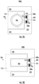
- FIGs. 1A and 1B are representative drawings of a snap-on assembly for sensing current across a conductor, such as a cable or busbar, according to exemplary embodiments.
- FIG. 1A is an overhead view of snap-on assembly 100A for affixation on a cable
- FIG. 1B is an overhead view of snap-on assembly 100B for affixation on a busbar (collectively, "snap-on assembly 100").
- the snap-on assembly 100 features a housing 102 with a first side 130, a second side 132, and a third side 134, with first side 130 being connected at one end to second side 132, first side 130 being perpendicular to second side 132, second side 132 being connected at an opposing end to third side 134, third side 134 being perpendicular to second side 132 at the opposing end, such that first side 130 and third side 134 are parallel to one another. From the overhead view, the first side 130, second side 132, and third side 134 look like a backwards letter "C" or a sideways letter "U".
- the snap-on assembly 100A of FIG. 1A measures the current across a cable 104.
- An inner insert 110 is placed in an opening 136 of the housing 102, followed by the cable 104, and an outer insert 112 is then placed in the housing.
- the inner insert 110 and the outer insert 112 surround the cable 104, holding the cable in place inside the opening 136 of the housing 102.
- the inner insert 110 and the outer insert 112 are made of a non-conductive material, such as plastic. The disclosed embodiments are not limiting in this regard.
- the snap-on assembly 100B of FIG. 1B measures the current across a busbar 106.
- one insert 114 is placed in the opening 136 to hold the busbar 106 in place.
- the insert 114 is shaped to surround the busbar 106, holding the busbar in place inside the opening 136 of the housing 102.
- the insert 114 is made of a non-conductive material, such as plastic. The disclosed embodiments are not limiting in this regard.
- the housing 102 of snap-on assembly 100A is not different from the housing of snap-on assembly 100B. Put another way, the housing 102 is interchangeable, whether the application is to perform current sensing of the cable 104 or of the busbar 106. By simply removing the inner insert 110 and the outer insert 112 and replacing them with insert 114, the application of the snap-on assembly 100 can change from the cable 104 to the busbar 106, and vice-versa.
- the outer insert 112 of the snap-on assembly 100A does not sit outside the threshold of the housing 102, while the insert 114 of the snap-on assembly 100B does sit outside the threshold of the housing. Because the busbar 106 has a width, w 1 , that is slightly smaller than the width, w 2 , of the opening 136, the insert 114 extends beyond the threshold of the housing 102. For a smaller busbar, this may not be the case. In exemplary embodiments, the insert 114 is also customizable to fit the dimensions of the busbar 106. Further, for a larger cable than the cable 104, the outer insert 112 may extend beyond the threshold of the housing 102.
- the outer insert 112 and the inner insert 110 are customizable to fit the circumferential dimension of the cable 104. In some embodiments, if the cable 104 is not circular, but is oval or some other shape, the outer insert 112 and the inner insert 110 are modified to fit with the shape of the cable. Further, for very large cables or busbars, that is, those that exceed the dimensions of the opening 136, the housing 102 of the snap-on assembly 100 is scaled to fit around the cables or busbars, in exemplary embodiments.
- the inserts may be modified to support different sizes and shapes of the conductor, whether a cable or a busbar.
- the busbar may be rectangular in shape or be a rounded rectangular shape, for example. Or, the busbar may have an atypical shape, such as a busbar that is custom-made to support a particular application.
- the cable may be isolated, such as with a sheath covering the copper cable. Or, the cable may be without isolation, such as for applications in which an increased current level is desired.
- the snap-on assembly 100 may feature modified inserts to facilitate the size and shape of the conductor.
- Sensors 108a and 108b are disposed in the first side 130 and third side 134, respectively, of the housing 102.
- the sensors 108 are Hall sensors, anisotropic magneto-resistive (AMR) sensors, or tunnel magnetoresistance (TMR) sensors. Magnetic field strength vectors B1 and B2 are shown for each sensor 108.
- the sensor 108b is optional, as the snap-on assembly 100 may operate with a single sensor 108a (non-compensated output signal) or may operate with both sensors (compensated output signal).
- each sensor 108 is an integrated circuits (IC) including a magnet to perform current sensing based on the magnetic field formed around the cable or busbar.
- IC integrated circuits
- two sensors are used so that stray magnetic fields can be detected and subtracted from the measured magnetic field of the current through the cable 104 or busbar 106.
- the sensors 108 send signals to an electronic circuit (not shown), for interpreting the measured current.
- the ICs can be placed on the top or bottom of the cable or busbar or placed on one side to share with the same printed circuit board assembly.
- FIGs. 2A and 2B are representative drawings of a second snap-on assembly for sensing current across a conductor, such as a cable or busbar, according to exemplary embodiments.
- FIG. 2A is an overhead view of snap-on assembly 200A for affixation on a cable
- FIG. 2B is an overhead view of snap-on assembly 200B for affixation on a busbar (collectively, "snap-on assembly 200").
- the snap-on assembly 200 features a housing 202 with first side 230, second side 232, and third side 234, with first side 230 being connected at one end and perpendicular to second side 232, second side 232 being connected at one end and perpendicular to first side 230 and at the other end and perpendicular to third side 234, such that first side 230 and third side 234 are parallel to on another.
- First side 230 and third side 234 may also be referred to herein as opposing sides. From the overhead view, the first side 230, second side 232, and third side 234 look like a backwards letter "C" or a sideways letter "U".
- the snap-on assembly 200A of FIG. 2A measures the current across a cable 204.
- An inner insert 210 is placed in an opening 236 of the housing 102, followed by the cable 204, and an outer insert 212 is then placed in the housing.
- the inner insert 210 and the outer insert 212 surround the cable 204, holding the cable in place inside the opening 236 of the housing 202.
- the inner insert 210 and the outer insert 212 are made of a non-conductive material, such as plastic. The disclosed embodiments are not limiting in this regard.
- the housing 202 of snap-on assembly 200A is not different from the housing of snap-on assembly 200B. As with the examples of FIGs. 1A and 1B , the housing 202 is interchangeable, whether the application is to perform current sensing of the cable 204 or of the busbar 206. By simply removing the insert 214 and replacing it with the inner insert 210 and the outer insert 212, the application of the snap-on assembly 200 can change from the busbar 206 to the cable 204, and vice-versa.
- the snap-on assembly 200B of FIG. 2B measures the current across a busbar 206.
- a single insert 214 is placed in the opening 236 to hold the busbar 206 in place.
- the insert 214 is shaped to surround the busbar 206, holding the busbar in place inside the opening 236 of the housing 202.
- the insert 214 is made of a non-conductive material, such as plastic. The disclosed embodiments are not limiting in this regard.
- Sensors 208a and 208b are disposed adjacent to one another in the second side 232 of the housing 202, with a concentrator 216 disposed against each sensor.
- the sensors 208 are Hall sensors, anisotropic magneto-resistive (AMR) sensors, or tunnel magnetoresistance (TMR) sensors. Magnetic field strength vectors B1 and B2 are shown for each sensor 208.
- the sensor 208b is optional, as the snap-on assembly 200 may operate with a single sensor 208a.
- each sensor 208 is an integrated circuits (IC) including a magnet to perform current sensing based on the magnetic field formed around the cable or busbar.
- IC integrated circuits
- two sensors are used so that stray magnetic fields can be detected and subtracted from the measured magnetic field of the current through the cable 204 or busbar 206.
- the sensors 208 send signals to an electronic circuit (not shown), for interpreting the measured current.
- FIGs. 3A and 3B are representative drawings of a snap-on assembly for sensing current across a conductor, such as a cable or busbar, according to exemplary embodiments.
- FIG. 3A is a perspective view of snap-on assembly 300A for affixation on a cable
- FIG. 3B is a perspective view of snap-on assembly 300B for affixation on a busbar (collectively, "snap-on assembly 300").
- the snap-on assembly 300A may include the features of either the snap-on assembly 100A or 200A
- the snap-on assembly 300B may include the features of either the snap-on assembly 100B or 200B.
- the snap-on assembly 300 features a housing 302 with first side 330, second side 332, and third side 334.
- the housing 302 may be configured with the ICs disposed as in FIGs. 1A-1B or as in FIGs. 2A-2B .
- cable 304 is shown disposed between the inner insert 310 and the outer insert 312, with the inner insert connected to the outer insert within the housing 302.
- the inner insert 310 and the outer insert 312 surround the cable 304, holding the cable in place inside the housing 302.
- a back surface 336 of the outer insert 312 mates with the first side 330 and third side 334 of the housing, thus forming a rectangular cube structure.
- busbar 306 is shown surrounded by insert 314.
- the insert 314 is shaped to surround the busbar 306, holding the busbar in place inside the housing 302.
- the inner insert 310, outer insert 312, and insert 314 are made of a non-conductive material, such as plastic. The disclosed embodiments are not limiting in this regard.
- a back surface 338 of the insert 314 mates with the first side 330 and third side 334 of the housing, thus forming a rectangular cube structure.
- the back surface 338 includes an opening 340 with depressions 342a and 342b (collectively, “depressions”).
- the depressions 342 are designed to press against the surface of the busbar 306, so as to prevent axial or longitudinal movement of the busbar. Axial movement or longitudinal movement of the busbar would be along its length, that is, to either side of the housing 302.
- the depressions 342 are described in more detail in conjunction with FIG. 4B , below.
- a connector 318 is disposed at the top of the housing, for connecting the sensors inside the housing (not shown) to a power source.
- the connector 318 in addition to supplying power to the snap-on assembly 300, further includes a dedicated pin for communicating the current signal sensed by the sensor ICs to an electrical circuit (not shown).
- FIGs. 4A and 4B are representative drawings of the snap-on assembly 300 of FIGs. 3A and 3B , according to exemplary embodiments.
- FIG. 4A is an exploded perspective view of the snap-on assembly 300A for affixation on the cable 304;
- FIG. 4B is an exploded perspective view of the snap-on assembly 300B for affixation on the busbar 306.
- the housing 302 includes the connector 318, as before, for connecting the snap-on assembly 300 to a power source and for communicating the sensed current signal to an electrical circuit.
- the cable 304 is shown disposed between the inner insert 310 and the outer insert 312, with the inside portion of the inner insert being exposed.
- the inner insert 310 include a cylindrical receptacle 422a including ribs 420 for receiving the cable 304 on one side.
- the outer insert 312 includes a cylindrical receptacle 422b including ribs (not shown) for receiving the cable 304 on the other side (collectively, "cylindrical receptacles 422").
- the ribs 420 protrude somewhat from respective cylindrical receptacles 422 so that, when the cable 304 is pressed against the inner insert 310 and the outer insert 312 is pressed against the cable, the ribs 420 are pressed against the cable.
- the inner insert 310 and the outer insert 312 secure the cable 304 in the housing 302 of the snap-on assembly 300A.
- the cylindrical receptacles 422 and the ribs 420 substantially prevent either rotational movement or axial movement of the cable 304 once the inner insert 310 and outer insert 312 are in place in the housing 302 of the snap-on assembly 300A.
- the inner insert 310 further includes arms 424a and 424b (collectively, “arms 424") and the outer insert 312 includes receiving sleeves 426a and 426b (collectively, 'receiving sleeves 426"), where arm 424a fits into receiving sleeve 426a and arm 424b fits into receiving sleeve 426b.
- the arm 424a is disposed on one side of the cable 304 (e.g., over the cable in FIG. 4A ) while the arm 424b is disposed on the other side of the cable (e.g., under the cable).
- the busbar 306 is shown inserted into the opening (e.g., opening 136 of snap-on assembly 100 or opening 236 of snap-on assembly 200, above) of the housing 302.
- the insert 314 includes a first leg 428a, a second leg 428b, a third leg 428c, and a fourth leg 428d (collectively, "legs 428"), which extend from the back surface 338 of the insert.
- the back surface 338 of the insert 314 includes an opening 340 with depressions 342.
- the depressions 342 are designed to press against the surface of the busbar 306, so as to prevent axial movement (e.g., to either side of the housing 302) of the busbar.
- the opening 340 and optional depressions 342 are not featured on the back surface 336 of insert 312 ( FIGs. 3A or 4A ). This is because the ribs 420 in the cylindrical receptacles 422 work to control rotation of the cable 304. Cable jackets tend to be elastic, which makes the ribs 420 stick to them quite well.
- Busbars on the other hand, are rigid and so the depressions 342 are pushed against the busbar 306 when the insert 314 is pressed into the housing 302.
- the snap-on assembly 300B has additional features to control movement of the busbar 306.
- legs 428a and 428c are disposed on one side of the busbar 306 (e.g., above the busbar in FIG. 4B ) while the legs 428b and 428d are disposed on the other side of the busbar (e.g., below the busbar).
- the legs 428a and 428b are disposed approximately a distance, w 3 , which corresponds to the width of the busbar 306.
- the legs 428c and 428d are disposed approximately a distance, w 3 , apart. This distance ensures that the legs 428 fit snugly around the busbar 306.
- the legs 428 prevent up-and-down movement of the busbar 306.
- the insert 314 secures the busbar 306 in the housing 302 of the snap-on assembly 300B. Further, in exemplary embodiments, the legs 428 of the insert 314 substantially prevent axial movement of the busbar 306 once the insert is in place in the housing 302 of the snap-on assembly 300B.
- the legs 428 further include features to ensure that the busbar 306 does not move.
- Dimples three of which are shown as dimple 430a on leg 428b and dimples 430b and 430c on leg 428d (collectively, "dimples 430"), help to provide clamping force onto the busbar, to secure the busbar 306 in place axially, much as the ribs 420 do for the cable 304 ( FIG. 3A ).
- Orthogonal protrusions two of which are shown, enhance the capacity of respective legs to grip the busbar 306 by giving support in another direction, that is, cross-wise, or along the shorter side of the busbar.
- orthogonal protrusions 432 thus provide another of control over the movement of the busbar 306 than the depressions 342.
- Orthogonal protrusion 432a is disposed at the end of leg 428a (opposite the back surface 338) and orthogonal protrusion 432b is disposed at the end of leg 428d (collectively, "orthogonal protrusions 432").
- the orthogonal protrusions 432 are oriented 90° from the respective legs 428.
- the orthogonal protrusions 432 are oriented out of plane from the respective legs 428 by some non-zero degree.
- the dimples 430 and orthogonal protrusions 432 help the legs 428 of the insert 314 to prevent axial movement of the busbar 306, in some embodiments.
- the depressions 342 of the opening 340 are pushed against the busbar 306, in some embodiments, which also controls axial movement.
- Exemplary embodiments of the snap-on assembly 300B may include one or more of these features to control movement of the busbar in the housing 302 in axial, cross-wise, and up-and-down movement. Put another way, these features control movement in the X-, Y-, and Z-directions.
- the snap-on assemblies 100, 200, and 300 can be secured to a conductor, such as a cable or busbar, without the use of a mechanical fasteners.
- mechanical fasteners are defined as hardware objects made of steel, iron, or other metal material, and may include bolts and nuts, screws, rivets, anchor fasteners, and the like.
- Legacy current sensors depend on a mechanical fastener to secure the sensor to the conductor. This dependence on mechanical fasteners can become problematic. For example, if the current sensor is secured to the conductor using a bolt and nut, and the nut becomes loose, the current sensor may move from its intended position on the conductor.
- a loose nut is more likely to be lost, such as in an automotive environment where the system itself, the vehicle, is designed to move. Once the nut is lost, it may not be long before the bolt is lost as well. Without its mechanical fastener, the reliability of the current sensor is thus compromised and may even be nonexistent.
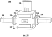
- FIGs. 5A and 5B are representative drawings of a snap-on assembly for sensing current across a conductor, such as a cable or busbar, according to exemplary embodiments.
- FIG. 5A is a perspective view of snap-on assembly 500A for affixation on a cable
- FIG. 5B is a perspective view of snap-on assembly 500B for affixation on a busbar (collectively, "snap-on assembly 500").
- the snap-on assembly 500A may include the features, such as the IC arrangement, of either the snap-on assembly 100A or 200A
- the snap-on assembly 500B may include the features of either the snap-on assembly 100B or 200B.
- the snap-on assembly 500 features material, known generally as extensions, added to the insert(s) for gripping the cable or busbar, such that it is secure inside the housing.
- the snap-on assembly 500A is much like the snap-on assemblies 100, 200, and 300 shown and described above.
- the snap-on assembly 500A includes a C- or U-shaped housing 502 and a connector 518, and an outer insert 512 is visible.
- the housing 502 features a cylindrical extension 528a connected to one side of the housing, and a cylindrical extension 528b connected to the opposing side of the housing (collectively, "cylindrical extensions 528").
- the cylindrical extensions are made of the same non-conductive material as the outer insert 512, such as plastic.
- the cylindrical extensions 528 are formed separately from the outer insert 512 and inner insert (not shown) but are fit into the outer and inner inserts. In other embodiments, the cylindrical extensions 528 are formed along with the outer insert 512 and the inner insert. In this case, the cylindrical extensions 528 would be made as two separate semi-circular structures on each side of the inner and outer inserts, with one semi-circular structure on each side of the inner insert being part of, and an extension of, the inner insert and molded as a unitary structure, while the other semi-circular structure on each side being part of, and an extension of, the outer insert 512 and molded as a unitary structure.
- the snap-on assembly 500A also includes wire ties 526a and 526b (collectively, “wire ties 526”), also known colloquially as “zip ties” or “flex cuffs”.
- the wire ties 526 fit into grooves 532 of the cylindrical extensions 528 and are wrapped around the cylindrical extensions.
- the wire ties 526 is a strip of plastic material that is somewhat flat, with a rectangular cross-section.
- Each wire tie 526 features a rectangular opening at one end that is usually not much larger than the dimension of the rectangular cross-section.
- One-way teeth are disposed along the surface of the wire tie 526. At the end opposite the rectangular opening is a somewhat flat, smooth lip.
- the lip end of the wire tie 526 is threaded through the rectangular opening, with the wire tie being positioned around an object to be secured, which is, in this example, one of the cylindrical extensions 528. Once the wire tie 526 is pulled taut (tightened) against the cylindrical extension 528, the one-way teeth prevent the wire tie from being loosened.
- the wire tie 526 is thus designed to be easy to fasten but difficult to release.
- the wire ties 526 are looped and tightened, as described above, to fixably secure the cylindrical extensions 528 to the cable 504. Because the cylindrical extensions 528 are connected to (or part of) the inserts 510 and 512, and the inserts are disposed within the opening of the housing 502, the cable will be secured within the housing of the snap-on assembly 500A. In contrast to mechanical fasteners such as nuts and bolts, the wire ties 526 are very reliable once secured around the cable 504, and do not loosen or break, even in extreme environments, such as when used in an operating vehicle. In exemplary embodiments, the wire ties 526, once secured to the cylindrical extensions 528, prevent both rotational and axial movement of the cable 504 inside the housing 502.
- snap-on assembly 500B is much like the snap-on assemblies 100, 200, and 300 shown and described above.
- the snap-on assembly 500B includes a C- or U-shaped housing 502 and a connector 518, and an insert 514 is visible.
- the housing 502 features a rectangular extension 530a connected to one side of the housing, and a rectangular extension 530b connected to the opposing side of the housing (collectively, "rectangular extensions 530").
- the rectangular extensions are made of the same non-conductive material as the insert 514, such as plastic.
- the rectangular extensions 530 are formed separately from the insert 514 but are fit into the insert.
- the rectangular extensions 530 are formed along with the insert 514.
- the rectangular extensions 530 would be disposed to the left and to the right of the insert 514 and molded as a unitary structure.
- the busbar 506 would be threaded through one rectangular extension 530a, through the opening of the insert 514, and through the rectangular extension 530b, or vice-versa, before being inserted into the opening of the housing 502.
- the rectangular extensions 530 include grooves 532, for receiving wire ties 526, in exemplary embodiments.
- the wire ties 526 fit into grooves 532 of the rectangular extensions 530 and are looped and tightened, as described above, to fixably secure the busbar 506 to the housing 502 of the snap-on assembly 500B.
- the wire ties 526 once secured to the rectangular extensions 530, prevent axial movement of the busbar 506 inside the housing 502.
- a novel snap-on assembly flexibly supports a conductor, such as a cable or busbar.
- the snap-on assembly is affixed to the conductor without need of mechanical fasteners, such as a screw and nuts, as in prior art current sensors.
- the snap-on assembly supports one sensor IC, for non-compensated signal outputs, or two sensor ICs, for compensated signal outputs.
- the inserts feature ribs, cylindrical receptacles, arms, and receiving sleeves to facilitate secure affixation, preventing rotational, axial, and up-and-down movement of the cable.
- the insert features legs, dimples, and orthogonal protrusions to facilitate secure affixation, preventing axial movement of the busbar.
- the inserts may be modified to support different sizes and shapes of both cables and busbars.
- the inserts may optionally be coupled with extensions for use with wire ties, for additional security of the cable or busbar.
Landscapes
- Physics & Mathematics (AREA)
- General Physics & Mathematics (AREA)
- Condensed Matter Physics & Semiconductors (AREA)
- Details Of Connecting Devices For Male And Female Coupling (AREA)
- Measuring Instrument Details And Bridges, And Automatic Balancing Devices (AREA)
Description
- Embodiments of the present disclosure relate to current sensors and, more particularly, to magnetic field-based current sensors.
- Current sensing is any one of several techniques used to measure electric current. Current sensors can measure current passively without interrupting the circuit by using the magnetic field to detect the current and generate an output that is proportional to the current.
- The current sensors are placed around the conductor of current, such as a cable or busbar, to perform the measurement. The current sensors are kept in place using a mechanical fastener, such as a screw with a nut to fix the sensor onto the busbar or cable. If one or more portions of the mechanical fastener becomes loose or lost, the current sensor becomes loose on the conductor, resulting in unreliable results or even loss of function. Different ways of securing conductors in current sensors can be seen in
US 2013/257469 A1 ,US 2015/309080 A1 ,US 2010/237853 A1 orEP 3 106 884 A1 . - It is with respect to these and other considerations that the present improvements may be useful.
- This Summary is provided to introduce a selection of concepts in a simplified form that are further described below in the Detailed Description. This Summary is not intended to identify key or essential features of the claimed subject matter, nor is it intended as an aid in determining the scope of the claimed subject matter.
- An exemplary embodiment of a snap-on assembly in accordance with the present disclosure may include a housing that holds an integrated circuit (IC) with a sensor. A connector supplies power to the IC and transmits a signal from the IC to an electronic circuit. An insert fits into an opening of the housing and secures a conductor in the housing without a mechanical fastener. The insert comprises a plurality of legs extending from a back surface of the insert, the plurality of legs comprising a first leg and a second leg to be placed on one side of the conductor as the insert is inserted into the opening of the housing, and a third leg and a fourth leg to be placed on an opposing side of the conductor as the insert is inserted into the opening of the housing.
- The sensor measures a magnetic field resulting from a current traveling through the conductor.
- Another exemplary embodiment of a snap-on assembly in accordance with the present disclosure may include a housing, an insert to fit into an opening of the housing, and two wire ties. The housing includes an IC with a sensor that measures a magnetic field resulting from a current traveling through a conductor. The insert secures the conductor in the housing without a mechanical fastener and includes a first extension to be placed on a first side of the housing and a second extension to be placed on a second, opposing side of the housing, the second side being opposite and parallel to the first side. The two extensions each include grooves. The first wire tie is to be looped around the first extension at the first groove and tightened. The second wire tie is to be looped around the second extension at the second groove and tightened. The conductor is inserted through the first extensions, through the insert, and through the second extension. The first and second wire ties secure the conductor in the housing.
-
-
FIGs. 1A-B are diagrams illustrating a snap-on assembly, in accordance with exemplary embodiments; -
FIGs. 2A-B are diagrams illustrating a snap-on assembly, in accordance with exemplary embodiments; -
FIGs. 3A-3B are diagrams illustrating a snap-on assembly, in accordance with exemplary embodiments; -
FIGs. 4A-4B are diagrams illustrating a snap-on assembly, in accordance with exemplary embodiments; and -
FIGs. 5A-5B are diagrams illustrating a snap-on assembly, in accordance with exemplary embodiments. - A snap-on assembly, for sensing current on a conductor, is disclosed for fitting onto a cable or busbar. The snap-on assembly is affixed to the cable or busbar without need of a mechanical fastener. A single housing is used for either the cable or the busbar. The housing of the snap-on assembly is used with one (busbar) or two (cable) plastic inserts which may be customized for different cable or busbar designs. The plastic inserts include features to prevent movement of the cable or busbar once the snap-on assembly is in place. The housing of the snap-on assembly optionally includes extensions to hold wire ties for additional security against movement.
- For the sake of convenience and clarity, terms such as "top", "bottom", "upper", "lower", "vertical", "horizontal", "lateral", "transverse", "radial", "inner", "outer", "left", and "right" may be used herein to describe the relative placement and orientation of the features and components of the electrical box, each with respect to the geometry and orientation of other features and components of the electrical box appearing in the perspective, exploded perspective, and cross-sectional views provided herein. Said terminology is not intended to be limiting and includes the words specifically mentioned, derivatives therein, and words of similar import.
-
FIGs. 1A and 1B are representative drawings of a snap-on assembly for sensing current across a conductor, such as a cable or busbar, according to exemplary embodiments.FIG. 1A is an overhead view of snap-onassembly 100A for affixation on a cable;FIG. 1B is an overhead view of snap-onassembly 100B for affixation on a busbar (collectively, "snap-on assembly 100"). The snap-on assembly 100 features ahousing 102 with afirst side 130, asecond side 132, and athird side 134, withfirst side 130 being connected at one end tosecond side 132,first side 130 being perpendicular tosecond side 132,second side 132 being connected at an opposing end tothird side 134,third side 134 being perpendicular tosecond side 132 at the opposing end, such thatfirst side 130 andthird side 134 are parallel to one another. From the overhead view, thefirst side 130,second side 132, andthird side 134 look like a backwards letter "C" or a sideways letter "U". - The snap-on
assembly 100A ofFIG. 1A measures the current across acable 104. Aninner insert 110 is placed in anopening 136 of thehousing 102, followed by thecable 104, and anouter insert 112 is then placed in the housing. In exemplary embodiments, theinner insert 110 and theouter insert 112 surround thecable 104, holding the cable in place inside theopening 136 of thehousing 102. In exemplary embodiments, theinner insert 110 and theouter insert 112 are made of a non-conductive material, such as plastic. The disclosed embodiments are not limiting in this regard. - The snap-on
assembly 100B ofFIG. 1B measures the current across abusbar 106. In contrast to the two-insert embodiment ofFIG. 1A , oneinsert 114 is placed in theopening 136 to hold thebusbar 106 in place. In exemplary embodiments, theinsert 114 is shaped to surround thebusbar 106, holding the busbar in place inside theopening 136 of thehousing 102. In exemplary embodiments, theinsert 114 is made of a non-conductive material, such as plastic. The disclosed embodiments are not limiting in this regard. - The
housing 102 of snap-onassembly 100A is not different from the housing of snap-onassembly 100B. Put another way, thehousing 102 is interchangeable, whether the application is to perform current sensing of thecable 104 or of thebusbar 106. By simply removing theinner insert 110 and theouter insert 112 and replacing them withinsert 114, the application of the snap-on assembly 100 can change from thecable 104 to thebusbar 106, and vice-versa. - In exemplary embodiments, the
outer insert 112 of the snap-onassembly 100A does not sit outside the threshold of thehousing 102, while theinsert 114 of the snap-onassembly 100B does sit outside the threshold of the housing. Because thebusbar 106 has a width, w1 , that is slightly smaller than the width, w2 , of theopening 136, theinsert 114 extends beyond the threshold of thehousing 102. For a smaller busbar, this may not be the case. In exemplary embodiments, theinsert 114 is also customizable to fit the dimensions of thebusbar 106. Further, for a larger cable than thecable 104, theouter insert 112 may extend beyond the threshold of thehousing 102. In exemplary embodiments, theouter insert 112 and theinner insert 110 are customizable to fit the circumferential dimension of thecable 104. In some embodiments, if thecable 104 is not circular, but is oval or some other shape, theouter insert 112 and theinner insert 110 are modified to fit with the shape of the cable. Further, for very large cables or busbars, that is, those that exceed the dimensions of theopening 136, thehousing 102 of the snap-on assembly 100 is scaled to fit around the cables or busbars, in exemplary embodiments. - The inserts may be modified to support different sizes and shapes of the conductor, whether a cable or a busbar. The busbar may be rectangular in shape or be a rounded rectangular shape, for example. Or, the busbar may have an atypical shape, such as a busbar that is custom-made to support a particular application. Further, the cable may be isolated, such as with a sheath covering the copper cable. Or, the cable may be without isolation, such as for applications in which an increased current level is desired. As long as the cross-section of the cable or the busbar is able to be fit within the
housing 102, the snap-on assembly 100 may feature modified inserts to facilitate the size and shape of the conductor. -
Sensors first side 130 andthird side 134, respectively, of thehousing 102. In some embodiments, the sensors 108 are Hall sensors, anisotropic magneto-resistive (AMR) sensors, or tunnel magnetoresistance (TMR) sensors. Magnetic field strength vectors B1 and B2 are shown for each sensor 108. In one embodiment, thesensor 108b is optional, as the snap-on assembly 100 may operate with asingle sensor 108a (non-compensated output signal) or may operate with both sensors (compensated output signal). - In exemplary embodiments, each sensor 108 is an integrated circuits (IC) including a magnet to perform current sensing based on the magnetic field formed around the cable or busbar. In exemplary embodiments, two sensors are used so that stray magnetic fields can be detected and subtracted from the measured magnetic field of the current through the
cable 104 orbusbar 106. In exemplary embodiments, the sensors 108 send signals to an electronic circuit (not shown), for interpreting the measured current. In exemplary embodiments, the ICs can be placed on the top or bottom of the cable or busbar or placed on one side to share with the same printed circuit board assembly. -
FIGs. 2A and 2B are representative drawings of a second snap-on assembly for sensing current across a conductor, such as a cable or busbar, according to exemplary embodiments.FIG. 2A is an overhead view of snap-onassembly 200A for affixation on a cable;FIG. 2B is an overhead view of snap-onassembly 200B for affixation on a busbar (collectively, "snap-on assembly 200"). The snap-on assembly 200 features ahousing 202 withfirst side 230,second side 232, andthird side 234, withfirst side 230 being connected at one end and perpendicular tosecond side 232,second side 232 being connected at one end and perpendicular tofirst side 230 and at the other end and perpendicular tothird side 234, such thatfirst side 230 andthird side 234 are parallel to on another.First side 230 andthird side 234 may also be referred to herein as opposing sides. From the overhead view, thefirst side 230,second side 232, andthird side 234 look like a backwards letter "C" or a sideways letter "U". - The snap-on
assembly 200A ofFIG. 2A measures the current across acable 204. Aninner insert 210 is placed in anopening 236 of thehousing 102, followed by thecable 204, and anouter insert 212 is then placed in the housing. In exemplary embodiments, theinner insert 210 and theouter insert 212 surround thecable 204, holding the cable in place inside theopening 236 of thehousing 202. In exemplary embodiments, theinner insert 210 and theouter insert 212 are made of a non-conductive material, such as plastic. The disclosed embodiments are not limiting in this regard. - The
housing 202 of snap-onassembly 200A is not different from the housing of snap-onassembly 200B. As with the examples ofFIGs. 1A and 1B , thehousing 202 is interchangeable, whether the application is to perform current sensing of thecable 204 or of thebusbar 206. By simply removing theinsert 214 and replacing it with theinner insert 210 and theouter insert 212, the application of the snap-on assembly 200 can change from thebusbar 206 to thecable 204, and vice-versa. - The snap-on
assembly 200B ofFIG. 2B measures the current across abusbar 206. Asingle insert 214 is placed in theopening 236 to hold thebusbar 206 in place. In exemplary embodiments, theinsert 214 is shaped to surround thebusbar 206, holding the busbar in place inside theopening 236 of thehousing 202. In exemplary embodiments, theinsert 214 is made of a non-conductive material, such as plastic. The disclosed embodiments are not limiting in this regard. -
Sensors second side 232 of thehousing 202, with aconcentrator 216 disposed against each sensor. In some embodiments, the sensors 208 are Hall sensors, anisotropic magneto-resistive (AMR) sensors, or tunnel magnetoresistance (TMR) sensors. Magnetic field strength vectors B1 and B2 are shown for each sensor 208. In one embodiment, thesensor 208b is optional, as the snap-on assembly 200 may operate with asingle sensor 208a. In exemplary embodiments, each sensor 208 is an integrated circuits (IC) including a magnet to perform current sensing based on the magnetic field formed around the cable or busbar. In exemplary embodiments, two sensors are used so that stray magnetic fields can be detected and subtracted from the measured magnetic field of the current through thecable 204 orbusbar 206. In exemplary embodiments, the sensors 208 send signals to an electronic circuit (not shown), for interpreting the measured current. -
FIGs. 3A and3B are representative drawings of a snap-on assembly for sensing current across a conductor, such as a cable or busbar, according to exemplary embodiments.FIG. 3A is a perspective view of snap-onassembly 300A for affixation on a cable;FIG. 3B is a perspective view of snap-onassembly 300B for affixation on a busbar (collectively, "snap-on assembly 300"). The snap-onassembly 300A may include the features of either the snap-onassembly assembly 300B may include the features of either the snap-onassembly - The snap-on assembly 300 features a
housing 302 withfirst side 330,second side 332, andthird side 334. Thehousing 302 may be configured with the ICs disposed as inFIGs. 1A-1B or as inFIGs. 2A-2B . InFIG. 3A ,cable 304 is shown disposed between theinner insert 310 and theouter insert 312, with the inner insert connected to the outer insert within thehousing 302. In exemplary embodiments, theinner insert 310 and theouter insert 312 surround thecable 304, holding the cable in place inside thehousing 302. Aback surface 336 of theouter insert 312 mates with thefirst side 330 andthird side 334 of the housing, thus forming a rectangular cube structure. - In
FIG. 3B ,busbar 306 is shown surrounded byinsert 314. In exemplary embodiments, theinsert 314 is shaped to surround thebusbar 306, holding the busbar in place inside thehousing 302. In exemplary embodiments, theinner insert 310,outer insert 312, and insert 314 are made of a non-conductive material, such as plastic. The disclosed embodiments are not limiting in this regard. Aback surface 338 of theinsert 314 mates with thefirst side 330 andthird side 334 of the housing, thus forming a rectangular cube structure. - In exemplary embodiments, the
back surface 338 includes anopening 340 withdepressions busbar 306, so as to prevent axial or longitudinal movement of the busbar. Axial movement or longitudinal movement of the busbar would be along its length, that is, to either side of thehousing 302. The depressions 342 are described in more detail in conjunction withFIG. 4B , below. - A
connector 318 is disposed at the top of the housing, for connecting the sensors inside the housing (not shown) to a power source. In one embodiment, in addition to supplying power to the snap-on assembly 300, theconnector 318 further includes a dedicated pin for communicating the current signal sensed by the sensor ICs to an electrical circuit (not shown). -
FIGs. 4A and4B are representative drawings of the snap-on assembly 300 ofFIGs. 3A and3B , according to exemplary embodiments.FIG. 4A is an exploded perspective view of the snap-onassembly 300A for affixation on thecable 304;FIG. 4B is an exploded perspective view of the snap-onassembly 300B for affixation on thebusbar 306. Thehousing 302 includes theconnector 318, as before, for connecting the snap-on assembly 300 to a power source and for communicating the sensed current signal to an electrical circuit. - In
FIG. 4A , thecable 304 is shown disposed between theinner insert 310 and theouter insert 312, with the inside portion of the inner insert being exposed. In exemplary embodiments, theinner insert 310 include acylindrical receptacle 422a including ribs 420 for receiving thecable 304 on one side. Similarly, theouter insert 312 includes acylindrical receptacle 422b including ribs (not shown) for receiving thecable 304 on the other side (collectively, "cylindrical receptacles 422"). Theribs 420 protrude somewhat from respective cylindrical receptacles 422 so that, when thecable 304 is pressed against theinner insert 310 and theouter insert 312 is pressed against the cable, theribs 420 are pressed against the cable. In exemplary embodiments, theinner insert 310 and theouter insert 312 secure thecable 304 in thehousing 302 of the snap-onassembly 300A. Further, in exemplary embodiments, the cylindrical receptacles 422 and theribs 420 substantially prevent either rotational movement or axial movement of thecable 304 once theinner insert 310 andouter insert 312 are in place in thehousing 302 of the snap-onassembly 300A. - In exemplary embodiments, the
inner insert 310 further includesarms outer insert 312 includes receivingsleeves arm 424a fits into receivingsleeve 426a andarm 424b fits into receivingsleeve 426b. Further, thearm 424a is disposed on one side of the cable 304 (e.g., over the cable inFIG. 4A ) while thearm 424b is disposed on the other side of the cable (e.g., under the cable). - In
FIG. 4B , thebusbar 306 is shown inserted into the opening (e.g., opening 136 of snap-on assembly 100 or opening 236 of snap-on assembly 200, above) of thehousing 302. Theinsert 314 includes afirst leg 428a, asecond leg 428b, athird leg 428c, and afourth leg 428d (collectively, "legs 428"), which extend from theback surface 338 of the insert. - As shown in
FIG. 3B , theback surface 338 of theinsert 314 includes anopening 340 with depressions 342. The depressions 342 are designed to press against the surface of thebusbar 306, so as to prevent axial movement (e.g., to either side of the housing 302) of the busbar. Theopening 340 and optional depressions 342 are not featured on theback surface 336 of insert 312 (FIGs. 3A or4A ). This is because theribs 420 in the cylindrical receptacles 422 work to control rotation of thecable 304. Cable jackets tend to be elastic, which makes theribs 420 stick to them quite well. Busbars, on the other hand, are rigid and so the depressions 342 are pushed against thebusbar 306 when theinsert 314 is pressed into thehousing 302. - In exemplary embodiments, the snap-on
assembly 300B has additional features to control movement of thebusbar 306. For example,legs FIG. 4B ) while thelegs legs busbar 306. Similarly, thelegs busbar 306. In exemplary embodiments, the legs 428 prevent up-and-down movement of thebusbar 306. In exemplary embodiments, theinsert 314 secures thebusbar 306 in thehousing 302 of the snap-onassembly 300B. Further, in exemplary embodiments, the legs 428 of theinsert 314 substantially prevent axial movement of thebusbar 306 once the insert is in place in thehousing 302 of the snap-onassembly 300B. - In exemplary embodiments, the legs 428 further include features to ensure that the
busbar 306 does not move. Dimples, three of which are shown as dimple 430a onleg 428b anddimples leg 428d (collectively, "dimples 430"), help to provide clamping force onto the busbar, to secure thebusbar 306 in place axially, much as theribs 420 do for the cable 304 (FIG. 3A ). Orthogonal protrusions, two of which are shown, enhance the capacity of respective legs to grip thebusbar 306 by giving support in another direction, that is, cross-wise, or along the shorter side of the busbar. As defined herein, cross-wise movement is perpendicular to axial movement, and up-and-down movement is perpendicular to both cross-wise and axial movement. The orthogonal protrusions 432 thus provide another of control over the movement of thebusbar 306 than the depressions 342.Orthogonal protrusion 432a is disposed at the end ofleg 428a (opposite the back surface 338) andorthogonal protrusion 432b is disposed at the end ofleg 428d (collectively, "orthogonal protrusions 432"). In one embodiment, the orthogonal protrusions 432 are oriented 90° from the respective legs 428. In other embodiments, the orthogonal protrusions 432 are oriented out of plane from the respective legs 428 by some non-zero degree. The dimples 430 and orthogonal protrusions 432 help the legs 428 of theinsert 314 to prevent axial movement of thebusbar 306, in some embodiments. Further, the depressions 342 of theopening 340 are pushed against thebusbar 306, in some embodiments, which also controls axial movement. Exemplary embodiments of the snap-onassembly 300B may include one or more of these features to control movement of the busbar in thehousing 302 in axial, cross-wise, and up-and-down movement. Put another way, these features control movement in the X-, Y-, and Z-directions. - In exemplary embodiments, the snap-on assemblies 100, 200, and 300 can be secured to a conductor, such as a cable or busbar, without the use of a mechanical fasteners. As used herein, mechanical fasteners are defined as hardware objects made of steel, iron, or other metal material, and may include bolts and nuts, screws, rivets, anchor fasteners, and the like. Legacy current sensors depend on a mechanical fastener to secure the sensor to the conductor. This dependence on mechanical fasteners can become problematic. For example, if the current sensor is secured to the conductor using a bolt and nut, and the nut becomes loose, the current sensor may move from its intended position on the conductor. Further, a loose nut is more likely to be lost, such as in an automotive environment where the system itself, the vehicle, is designed to move. Once the nut is lost, it may not be long before the bolt is lost as well. Without its mechanical fastener, the reliability of the current sensor is thus compromised and may even be nonexistent.
-
FIGs. 5A and5B are representative drawings of a snap-on assembly for sensing current across a conductor, such as a cable or busbar, according to exemplary embodiments.FIG. 5A is a perspective view of snap-onassembly 500A for affixation on a cable;FIG. 5B is a perspective view of snap-onassembly 500B for affixation on a busbar (collectively, "snap-on assembly 500"). The snap-onassembly 500A may include the features, such as the IC arrangement, of either the snap-onassembly assembly 500B may include the features of either the snap-onassembly - Looking first at
FIG. 5A , the snap-onassembly 500A is much like the snap-on assemblies 100, 200, and 300 shown and described above. The snap-onassembly 500A includes a C- orU-shaped housing 502 and aconnector 518, and anouter insert 512 is visible. Further, in some embodiments, thehousing 502 features acylindrical extension 528a connected to one side of the housing, and acylindrical extension 528b connected to the opposing side of the housing (collectively, "cylindrical extensions 528"). In exemplary embodiments, the cylindrical extensions are made of the same non-conductive material as theouter insert 512, such as plastic. In some embodiments, the cylindrical extensions 528 are formed separately from theouter insert 512 and inner insert (not shown) but are fit into the outer and inner inserts. In other embodiments, the cylindrical extensions 528 are formed along with theouter insert 512 and the inner insert. In this case, the cylindrical extensions 528 would be made as two separate semi-circular structures on each side of the inner and outer inserts, with one semi-circular structure on each side of the inner insert being part of, and an extension of, the inner insert and molded as a unitary structure, while the other semi-circular structure on each side being part of, and an extension of, theouter insert 512 and molded as a unitary structure. - In exemplary embodiments, the snap-on
assembly 500A also includeswire ties grooves 532 of the cylindrical extensions 528 and are wrapped around the cylindrical extensions. The wire ties 526 is a strip of plastic material that is somewhat flat, with a rectangular cross-section. Each wire tie 526 features a rectangular opening at one end that is usually not much larger than the dimension of the rectangular cross-section. One-way teeth are disposed along the surface of the wire tie 526. At the end opposite the rectangular opening is a somewhat flat, smooth lip. The lip end of the wire tie 526 is threaded through the rectangular opening, with the wire tie being positioned around an object to be secured, which is, in this example, one of the cylindrical extensions 528. Once the wire tie 526 is pulled taut (tightened) against the cylindrical extension 528, the one-way teeth prevent the wire tie from being loosened. The wire tie 526 is thus designed to be easy to fasten but difficult to release. - In exemplary embodiments, the wire ties 526 are looped and tightened, as described above, to fixably secure the cylindrical extensions 528 to the
cable 504. Because the cylindrical extensions 528 are connected to (or part of) theinserts 510 and 512, and the inserts are disposed within the opening of thehousing 502, the cable will be secured within the housing of the snap-onassembly 500A. In contrast to mechanical fasteners such as nuts and bolts, the wire ties 526 are very reliable once secured around thecable 504, and do not loosen or break, even in extreme environments, such as when used in an operating vehicle. In exemplary embodiments, the wire ties 526, once secured to the cylindrical extensions 528, prevent both rotational and axial movement of thecable 504 inside thehousing 502. - As illustrated in
FIG. 5B , snap-onassembly 500B is much like the snap-on assemblies 100, 200, and 300 shown and described above. The snap-onassembly 500B includes a C- orU-shaped housing 502 and aconnector 518, and aninsert 514 is visible. Further, in some embodiments, thehousing 502 features arectangular extension 530a connected to one side of the housing, and arectangular extension 530b connected to the opposing side of the housing (collectively, "rectangular extensions 530"). In exemplary embodiments, the rectangular extensions are made of the same non-conductive material as theinsert 514, such as plastic. In some embodiments, the rectangular extensions 530 are formed separately from theinsert 514 but are fit into the insert. In other embodiments, the rectangular extensions 530 are formed along with theinsert 514. In this case, the rectangular extensions 530 would be disposed to the left and to the right of theinsert 514 and molded as a unitary structure. And thebusbar 506 would be threaded through onerectangular extension 530a, through the opening of theinsert 514, and through therectangular extension 530b, or vice-versa, before being inserted into the opening of thehousing 502. - As with the cylindrical extensions 528 (
FIG. 5A ), the rectangular extensions 530 includegrooves 532, for receiving wire ties 526, in exemplary embodiments. The wire ties 526 fit intogrooves 532 of the rectangular extensions 530 and are looped and tightened, as described above, to fixably secure thebusbar 506 to thehousing 502 of the snap-onassembly 500B. In exemplary embodiments, the wire ties 526, once secured to the rectangular extensions 530, prevent axial movement of thebusbar 506 inside thehousing 502. - Thus, a novel snap-on assembly flexibly supports a conductor, such as a cable or busbar. The snap-on assembly is affixed to the conductor without need of mechanical fasteners, such as a screw and nuts, as in prior art current sensors. The snap-on assembly supports one sensor IC, for non-compensated signal outputs, or two sensor ICs, for compensated signal outputs. For the cable assembly, the inserts feature ribs, cylindrical receptacles, arms, and receiving sleeves to facilitate secure affixation, preventing rotational, axial, and up-and-down movement of the cable. For the busbar assembly, the insert features legs, dimples, and orthogonal protrusions to facilitate secure affixation, preventing axial movement of the busbar. The inserts may be modified to support different sizes and shapes of both cables and busbars. The inserts may optionally be coupled with extensions for use with wire ties, for additional security of the cable or busbar.
- As used herein, an element or step recited in the singular and proceeded with the word "a" or "an" should be understood as not excluding plural elements or steps, unless such exclusion is explicitly recited. Furthermore, references to "one embodiment" of the present disclosure are not intended to be interpreted as excluding the existence of additional embodiments that also incorporate the recited features.
- The invention is defined by the appended claims.
Claims (14)
- A snap-on assembly (100a, 100b, 200a, 200b, 300a, 300b) comprising:a housing (102, 202, 302) comprising an integrated circuit, IC, the IC comprising a sensor;a connector (318) to supply power to the IC and to transmit a signal from the IC to an electronic circuit; andan insert (110, 210, 310) to fit into an opening of the housing, the insert to secure a conductor in the housing without a mechanical fastener, wherein the sensor measures a magnetic field resulting from a current travelling through the conductor,characterized in the insert further comprising a plurality of legs (428) extending from a back surface of the insert, the plurality of legs comprising:a first leg (428a) and a second leg (428b) to be placed on one side of the conductor as the insert is inserted into the opening of the housing; anda third leg (428c) and a fourth leg (428d) to be placed on an opposing side of the conductor as the insert is inserted into the opening of the housing.
- The snap-on assembly of claim 1, wherein the conductor is a cable.
- The snap-on assembly of claim 2, further comprising a second insert, wherein the second insert is placed the opening of the housing, followed by the cable, and followed by the insert.
- The snap-on assembly of claim 3, the insert and the second insert further comprising:a cylindrical receptacle; anda plurality of ribs, wherein the plurality of ribs fit against the cable once secured in the housing.
- The snap-on assembly of claim 3 or 4, wherein the insert and the second insert prevent rotational movement and/or axial movement of the cable.
- The snap-on assembly of any of the claims 3-5, wherein the insert and the second insert are made of a non-conductive plastic.
- The snap-on assembly of any of the preceding claims, wherein the conductor is a busbar.
- The snap-on assembly of claim 1, wherein a distance between the first leg and the third leg is approximately a width of the busbar.
- The snap-on assembly of claim 1 or 8 , further comprising:dimples disposed on one or more of the plurality of legs; andorthogonal protrusions disposed on one or more of the plurality of legs, preferably wherein the dimples and orthogonal protrusions prevent axial movement of the busbar in the housing.
- The snap-on assembly of any of the preceding claims, further comprising a second IC, the second IC comprising a second sensor, wherein the IC and the second IC generate compensated signals.
- The snap-on assembly of any of the preceding claims, the housing further comprising a first side, a second side, and a third side, the first side being coupled to the second side, the first side being perpendicular to the second side, the second side being coupled to the third side, the second side being perpendicular to the third side, wherein the first side is parallel to the third side, preferably wherein the IC is disposed on the first side and the second IC is disposed on the third side, preferably wherein the IC and the second IC are disposed on the second side.
- The snap-on assembly of claim 1, further comprising:a first extension to be disposed on a first side of the housing, the first extension comprising a first groove; anda second extension to be disposed on a second side of the housing, the second side being opposite the first side, wherein the first side is parallel to the second side, the second extension comprising a second groove;a first wire tie to be looped around the first extension at the first groove and tightened; anda second wire tie to be looped around the second extension at the second groove and tightened;
wherein the conductor is inserted through the first extension, through the insert, and through the second extension and the first wire tie and the second wire tie secure the conductor in the housing. - The snap-on assembly of claim 12, further comprising a second IC, the second IC comprising a second sensor, wherein the IC and the second IC generate non-compensated signals.
- The snap-on assembly of claim 12 or 13, wherein the conductor is a cable, the first extension is a first cylindrical extension, and the second extension is a second cylindrical extension, preferably wherein the conductor is a busbar, the first extension is a first rectangular extension, and the second extension is a second rectangular extension.
Priority Applications (1)
| Application Number | Priority Date | Filing Date | Title |
|---|---|---|---|
| EP25181272.3A EP4589318A3 (en) | 2021-08-06 | 2022-07-15 | A snap-on current sensor design |
Applications Claiming Priority (1)
| Application Number | Priority Date | Filing Date | Title |
|---|---|---|---|
| CN202110900035.0A CN115902303A (en) | 2021-08-06 | 2021-08-06 | Buckle type current sensor design |
Related Child Applications (1)
| Application Number | Title | Priority Date | Filing Date |
|---|---|---|---|
| EP25181272.3A Division EP4589318A3 (en) | 2021-08-06 | 2022-07-15 | A snap-on current sensor design |
Publications (2)
| Publication Number | Publication Date |
|---|---|
| EP4130756A1 EP4130756A1 (en) | 2023-02-08 |
| EP4130756B1 true EP4130756B1 (en) | 2025-06-11 |
Family
ID=82608067
Family Applications (2)
| Application Number | Title | Priority Date | Filing Date |
|---|---|---|---|
| EP22185310.4A Active EP4130756B1 (en) | 2021-08-06 | 2022-07-15 | A snap-on current sensor design |
| EP25181272.3A Pending EP4589318A3 (en) | 2021-08-06 | 2022-07-15 | A snap-on current sensor design |
Family Applications After (1)
| Application Number | Title | Priority Date | Filing Date |
|---|---|---|---|
| EP25181272.3A Pending EP4589318A3 (en) | 2021-08-06 | 2022-07-15 | A snap-on current sensor design |
Country Status (4)
| Country | Link |
|---|---|
| US (2) | US12313656B2 (en) |
| EP (2) | EP4130756B1 (en) |
| JP (1) | JP2023024309A (en) |
| CN (1) | CN115902303A (en) |
Families Citing this family (4)
| Publication number | Priority date | Publication date | Assignee | Title |
|---|---|---|---|---|
| JP7234880B2 (en) * | 2019-09-20 | 2023-03-08 | 株式会社三洋物産 | game machine |
| JP7234877B2 (en) * | 2019-09-20 | 2023-03-08 | 株式会社三洋物産 | game machine |
| TWI908190B (en) * | 2023-07-13 | 2025-12-11 | 美商莫仕有限公司 | Hall effect electrical flux detector connector and method thereof |
| US12598708B2 (en) | 2023-11-30 | 2026-04-07 | Caterpillar Inc. | Detachable sensor assembly for an elongate conductor |
Family Cites Families (15)
| Publication number | Priority date | Publication date | Assignee | Title |
|---|---|---|---|---|
| JP2000088889A (en) * | 1998-09-10 | 2000-03-31 | Tokin Corp | Current transformer and equipment using it |
| WO2008033527A2 (en) * | 2006-09-14 | 2008-03-20 | Ambient Corporation | Housing for inductive coupler for power line communications |
| JP4629644B2 (en) * | 2006-10-31 | 2011-02-09 | 株式会社東海理化電機製作所 | Current detector |
| JP5222542B2 (en) * | 2007-12-07 | 2013-06-26 | 矢崎総業株式会社 | Current sensor |
| JP5047919B2 (en) * | 2008-10-03 | 2012-10-10 | 矢崎総業株式会社 | Current sensor |
| US8193803B2 (en) * | 2009-03-23 | 2012-06-05 | Consolidated Edison Company Of New York, Inc. | Current measuring device |
| JP2013142623A (en) * | 2012-01-11 | 2013-07-22 | Toyota Industries Corp | Current sensor |
| JP5935019B2 (en) * | 2012-03-29 | 2016-06-15 | アルプス・グリーンデバイス株式会社 | Current sensor |
| KR200471248Y1 (en) * | 2012-12-07 | 2014-02-11 | 김용현 | Current Transformer |
| US20140312893A1 (en) * | 2013-03-14 | 2014-10-23 | Don Burkart | Intelligent electronic sensors for monitoring electrical circuits |
| WO2015029736A1 (en) * | 2013-08-29 | 2015-03-05 | アルプス・グリーンデバイス株式会社 | Current sensor |
| WO2015122064A1 (en) * | 2014-02-13 | 2015-08-20 | アルプス・グリーンデバイス株式会社 | Current sensor |
| EP2942631B1 (en) * | 2014-04-28 | 2024-03-06 | TYCO ELECTRONICS AMP KOREA Co., Ltd. | Hybrid current sensor assembly |
| JP2018054588A (en) * | 2016-09-26 | 2018-04-05 | 甲神電機株式会社 | Current sensor |
| JP6495364B2 (en) * | 2017-03-27 | 2019-04-03 | 株式会社タムラ製作所 | Current detector |
-
2021
- 2021-08-06 CN CN202110900035.0A patent/CN115902303A/en active Pending
-
2022
- 2022-07-15 EP EP22185310.4A patent/EP4130756B1/en active Active
- 2022-07-15 EP EP25181272.3A patent/EP4589318A3/en active Pending
- 2022-07-19 JP JP2022114498A patent/JP2023024309A/en active Pending
- 2022-07-29 US US17/816,027 patent/US12313656B2/en active Active
-
2025
- 2025-04-25 US US19/189,467 patent/US20250251426A1/en active Pending
Also Published As
| Publication number | Publication date |
|---|---|
| JP2023024309A (en) | 2023-02-16 |
| US20230042505A1 (en) | 2023-02-09 |
| EP4130756A1 (en) | 2023-02-08 |
| CN115902303A (en) | 2023-04-04 |
| EP4589318A2 (en) | 2025-07-23 |
| US20250251426A1 (en) | 2025-08-07 |
| EP4589318A3 (en) | 2025-10-22 |
| US12313656B2 (en) | 2025-05-27 |
Similar Documents
| Publication | Publication Date | Title |
|---|---|---|
| EP4130756A1 (en) | A snap-on current sensor design | |
| EP2619598B1 (en) | Current detecting device and attaching structure thereof | |
| KR101395383B1 (en) | Apparatus for measuring an electric current flowing through an electrical conductor | |
| TWI260370B (en) | Sensor attachment mechanism for fluid pressure cylinder | |
| US7583072B2 (en) | Current sensor for measuring current flowing through bus bar | |
| US9557352B2 (en) | Current detection structure | |
| EP2963428A1 (en) | Current sensor and electronic device containing same | |
| US6781359B2 (en) | Integrated current sensor | |
| JP7842535B2 (en) | Non-contact voltage measurement using an adjustable-size Rogowski coil | |
| JP2000321309A (en) | Fixed type current detector | |
| US12044708B2 (en) | Differential signal current sensor | |
| KR102955264B1 (en) | Electrical device for receiving a magnetic field measurement sensor | |
| EP3306325A1 (en) | A current measuring device | |
| RU2717397C1 (en) | Device and method for measuring current strength of one separate wire of multi-wire system | |
| JP4798141B2 (en) | Current sensor mounting structure | |
| MX2010001276A (en) | Method and apparatus for measuring current output of low-voltage pad-mount distribution power transformers. | |
| JP2014055791A (en) | Current sensor | |
| KR101908606B1 (en) | Apparatus for sensing of load of cable | |
| EP2921864B1 (en) | Current Sensor | |
| KR20220073693A (en) | Electrical device for measuring a magnetic field in order to perform a current measurement | |
| JP5683511B2 (en) | Current sensor | |
| JP6019423B2 (en) | Adapter for current measurement | |
| US8057251B2 (en) | Stay-tight mechanism for coaxial gradient coil terminals | |
| KR101623727B1 (en) | A power quality measurement device and power per load | |
| US20250264493A1 (en) | Sensor for detecting a rotational speed and/or direction of rotation of a wheel of a vehicle, system comprising such a sensor, and vehicle comprising such a system |
Legal Events
| Date | Code | Title | Description |
|---|---|---|---|
| PUAI | Public reference made under article 153(3) epc to a published international application that has entered the european phase |
Free format text: ORIGINAL CODE: 0009012 |
|
| STAA | Information on the status of an ep patent application or granted ep patent |
Free format text: STATUS: THE APPLICATION HAS BEEN PUBLISHED |
|
| AK | Designated contracting states |
Kind code of ref document: A1 Designated state(s): AL AT BE BG CH CY CZ DE DK EE ES FI FR GB GR HR HU IE IS IT LI LT LU LV MC MK MT NL NO PL PT RO RS SE SI SK SM TR |
|
| STAA | Information on the status of an ep patent application or granted ep patent |
Free format text: STATUS: REQUEST FOR EXAMINATION WAS MADE |
|
| 17P | Request for examination filed |
Effective date: 20230804 |
|
| RBV | Designated contracting states (corrected) |
Designated state(s): AL AT BE BG CH CY CZ DE DK EE ES FI FR GB GR HR HU IE IS IT LI LT LU LV MC MK MT NL NO PL PT RO RS SE SI SK SM TR |
|
| REG | Reference to a national code |
Ref country code: DE Ref country code: DE Ref legal event code: R079 Ref document number: 602022015740 Country of ref document: DE Free format text: PREVIOUS MAIN CLASS: G01R0001040000 Ipc: G01R0033000000 |
|
| RIC1 | Information provided on ipc code assigned before grant |
Ipc: G01R 33/07 20060101ALI20241217BHEP Ipc: G01R 15/20 20060101ALI20241217BHEP Ipc: G01R 1/04 20060101ALI20241217BHEP Ipc: G01R 33/09 20060101ALI20241217BHEP Ipc: G01R 33/00 20060101AFI20241217BHEP |
|
| GRAP | Despatch of communication of intention to grant a patent |
Free format text: ORIGINAL CODE: EPIDOSNIGR1 |
|
| STAA | Information on the status of an ep patent application or granted ep patent |
Free format text: STATUS: GRANT OF PATENT IS INTENDED |
|
| INTG | Intention to grant announced |
Effective date: 20250228 |
|
| GRAS | Grant fee paid |
Free format text: ORIGINAL CODE: EPIDOSNIGR3 |
|
| P01 | Opt-out of the competence of the unified patent court (upc) registered |
Free format text: CASE NUMBER: APP_15611/2025 Effective date: 20250331 |
|
| GRAA | (expected) grant |
Free format text: ORIGINAL CODE: 0009210 |
|
| STAA | Information on the status of an ep patent application or granted ep patent |
Free format text: STATUS: THE PATENT HAS BEEN GRANTED |
|
| AK | Designated contracting states |
Kind code of ref document: B1 Designated state(s): AL AT BE BG CH CY CZ DE DK EE ES FI FR GB GR HR HU IE IS IT LI LT LU LV MC MK MT NL NO PL PT RO RS SE SI SK SM TR |
|
| REG | Reference to a national code |
Ref country code: GB Ref legal event code: FG4D |
|
| REG | Reference to a national code |
Ref country code: CH Ref legal event code: EP |
|
| REG | Reference to a national code |
Ref country code: IE Ref legal event code: FG4D |
|
| REG | Reference to a national code |
Ref country code: DE Ref legal event code: R096 Ref document number: 602022015740 Country of ref document: DE |
|
| PG25 | Lapsed in a contracting state [announced via postgrant information from national office to epo] |
Ref country code: ES Free format text: LAPSE BECAUSE OF FAILURE TO SUBMIT A TRANSLATION OF THE DESCRIPTION OR TO PAY THE FEE WITHIN THE PRESCRIBED TIME-LIMIT Effective date: 20250611 Ref country code: FI Free format text: LAPSE BECAUSE OF FAILURE TO SUBMIT A TRANSLATION OF THE DESCRIPTION OR TO PAY THE FEE WITHIN THE PRESCRIBED TIME-LIMIT Effective date: 20250611 |
|
| PGFP | Annual fee paid to national office [announced via postgrant information from national office to epo] |
Ref country code: DE Payment date: 20250708 Year of fee payment: 4 |
|
| REG | Reference to a national code |
Ref country code: LT Ref legal event code: MG9D |
|
| PG25 | Lapsed in a contracting state [announced via postgrant information from national office to epo] |
Ref country code: NO Free format text: LAPSE BECAUSE OF FAILURE TO SUBMIT A TRANSLATION OF THE DESCRIPTION OR TO PAY THE FEE WITHIN THE PRESCRIBED TIME-LIMIT Effective date: 20250911 Ref country code: GR Free format text: LAPSE BECAUSE OF FAILURE TO SUBMIT A TRANSLATION OF THE DESCRIPTION OR TO PAY THE FEE WITHIN THE PRESCRIBED TIME-LIMIT Effective date: 20250912 |
|
| PGFP | Annual fee paid to national office [announced via postgrant information from national office to epo] |
Ref country code: IT Payment date: 20250731 Year of fee payment: 4 |
|
| REG | Reference to a national code |
Ref country code: NL Ref legal event code: MP Effective date: 20250611 |
|
| PG25 | Lapsed in a contracting state [announced via postgrant information from national office to epo] |
Ref country code: BG Free format text: LAPSE BECAUSE OF FAILURE TO SUBMIT A TRANSLATION OF THE DESCRIPTION OR TO PAY THE FEE WITHIN THE PRESCRIBED TIME-LIMIT Effective date: 20250611 |
|
| PG25 | Lapsed in a contracting state [announced via postgrant information from national office to epo] |
Ref country code: HR Free format text: LAPSE BECAUSE OF FAILURE TO SUBMIT A TRANSLATION OF THE DESCRIPTION OR TO PAY THE FEE WITHIN THE PRESCRIBED TIME-LIMIT Effective date: 20250611 |
|
| PGFP | Annual fee paid to national office [announced via postgrant information from national office to epo] |
Ref country code: AT Payment date: 20251020 Year of fee payment: 4 Ref country code: FR Payment date: 20250708 Year of fee payment: 4 |
|
| PG25 | Lapsed in a contracting state [announced via postgrant information from national office to epo] |
Ref country code: RS Free format text: LAPSE BECAUSE OF FAILURE TO SUBMIT A TRANSLATION OF THE DESCRIPTION OR TO PAY THE FEE WITHIN THE PRESCRIBED TIME-LIMIT Effective date: 20250911 |
|
| PG25 | Lapsed in a contracting state [announced via postgrant information from national office to epo] |
Ref country code: LV Free format text: LAPSE BECAUSE OF FAILURE TO SUBMIT A TRANSLATION OF THE DESCRIPTION OR TO PAY THE FEE WITHIN THE PRESCRIBED TIME-LIMIT Effective date: 20250611 |
|
| PG25 | Lapsed in a contracting state [announced via postgrant information from national office to epo] |
Ref country code: NL Free format text: LAPSE BECAUSE OF FAILURE TO SUBMIT A TRANSLATION OF THE DESCRIPTION OR TO PAY THE FEE WITHIN THE PRESCRIBED TIME-LIMIT Effective date: 20250611 |
|
| PG25 | Lapsed in a contracting state [announced via postgrant information from national office to epo] |
Ref country code: PT Free format text: LAPSE BECAUSE OF FAILURE TO SUBMIT A TRANSLATION OF THE DESCRIPTION OR TO PAY THE FEE WITHIN THE PRESCRIBED TIME-LIMIT Effective date: 20251013 |
|
| REG | Reference to a national code |
Ref country code: AT Ref legal event code: MK05 Ref document number: 1802678 Country of ref document: AT Kind code of ref document: T Effective date: 20250611 |
|
| PG25 | Lapsed in a contracting state [announced via postgrant information from national office to epo] |
Ref country code: IS Free format text: LAPSE BECAUSE OF FAILURE TO SUBMIT A TRANSLATION OF THE DESCRIPTION OR TO PAY THE FEE WITHIN THE PRESCRIBED TIME-LIMIT Effective date: 20251011 |
|
| PG25 | Lapsed in a contracting state [announced via postgrant information from national office to epo] |
Ref country code: AT Free format text: LAPSE BECAUSE OF FAILURE TO SUBMIT A TRANSLATION OF THE DESCRIPTION OR TO PAY THE FEE WITHIN THE PRESCRIBED TIME-LIMIT Effective date: 20250611 Ref country code: SM Free format text: LAPSE BECAUSE OF FAILURE TO SUBMIT A TRANSLATION OF THE DESCRIPTION OR TO PAY THE FEE WITHIN THE PRESCRIBED TIME-LIMIT Effective date: 20250611 |
|
| PG25 | Lapsed in a contracting state [announced via postgrant information from national office to epo] |
Ref country code: CZ Free format text: LAPSE BECAUSE OF FAILURE TO SUBMIT A TRANSLATION OF THE DESCRIPTION OR TO PAY THE FEE WITHIN THE PRESCRIBED TIME-LIMIT Effective date: 20250611 |
|
| PG25 | Lapsed in a contracting state [announced via postgrant information from national office to epo] |
Ref country code: PL Free format text: LAPSE BECAUSE OF FAILURE TO SUBMIT A TRANSLATION OF THE DESCRIPTION OR TO PAY THE FEE WITHIN THE PRESCRIBED TIME-LIMIT Effective date: 20250611 |
|
| PG25 | Lapsed in a contracting state [announced via postgrant information from national office to epo] |
Ref country code: EE Free format text: LAPSE BECAUSE OF FAILURE TO SUBMIT A TRANSLATION OF THE DESCRIPTION OR TO PAY THE FEE WITHIN THE PRESCRIBED TIME-LIMIT Effective date: 20250611 |
|
| PG25 | Lapsed in a contracting state [announced via postgrant information from national office to epo] |
Ref country code: SK Free format text: LAPSE BECAUSE OF FAILURE TO SUBMIT A TRANSLATION OF THE DESCRIPTION OR TO PAY THE FEE WITHIN THE PRESCRIBED TIME-LIMIT Effective date: 20250611 |
|
| PG25 | Lapsed in a contracting state [announced via postgrant information from national office to epo] |
Ref country code: RO Free format text: LAPSE BECAUSE OF FAILURE TO SUBMIT A TRANSLATION OF THE DESCRIPTION OR TO PAY THE FEE WITHIN THE PRESCRIBED TIME-LIMIT Effective date: 20250611 |
|
| REG | Reference to a national code |
Ref country code: CH Ref legal event code: H13 Free format text: ST27 STATUS EVENT CODE: U-0-0-H10-H13 (AS PROVIDED BY THE NATIONAL OFFICE) Effective date: 20260224 |
|
| REG | Reference to a national code |
Ref country code: DE Ref legal event code: R097 Ref document number: 602022015740 Country of ref document: DE |
|
| PG25 | Lapsed in a contracting state [announced via postgrant information from national office to epo] |
Ref country code: LU Free format text: LAPSE BECAUSE OF NON-PAYMENT OF DUE FEES Effective date: 20250715 |
|
| REG | Reference to a national code |
Ref country code: BE Ref legal event code: MM Effective date: 20250731 |
|
| PG25 | Lapsed in a contracting state [announced via postgrant information from national office to epo] |
Ref country code: MC Free format text: LAPSE BECAUSE OF FAILURE TO SUBMIT A TRANSLATION OF THE DESCRIPTION OR TO PAY THE FEE WITHIN THE PRESCRIBED TIME-LIMIT Effective date: 20250611 |
|
| PG25 | Lapsed in a contracting state [announced via postgrant information from national office to epo] |
Ref country code: DK Free format text: LAPSE BECAUSE OF FAILURE TO SUBMIT A TRANSLATION OF THE DESCRIPTION OR TO PAY THE FEE WITHIN THE PRESCRIBED TIME-LIMIT Effective date: 20250611 |
|
| PG25 | Lapsed in a contracting state [announced via postgrant information from national office to epo] |
Ref country code: BE Free format text: LAPSE BECAUSE OF NON-PAYMENT OF DUE FEES Effective date: 20250731 |
|
| PLBE | No opposition filed within time limit |
Free format text: ORIGINAL CODE: 0009261 |
|
| STAA | Information on the status of an ep patent application or granted ep patent |
Free format text: STATUS: NO OPPOSITION FILED WITHIN TIME LIMIT |
|
| PG25 | Lapsed in a contracting state [announced via postgrant information from national office to epo] |
Ref country code: CH Free format text: LAPSE BECAUSE OF NON-PAYMENT OF DUE FEES Effective date: 20250731 |
|
| REG | Reference to a national code |
Ref country code: CH Ref legal event code: L10 Free format text: ST27 STATUS EVENT CODE: U-0-0-L10-L00 (AS PROVIDED BY THE NATIONAL OFFICE) Effective date: 20260423 |