EP4130738A1 - Optical measurement device and optical measurement method - Google Patents
Optical measurement device and optical measurement method Download PDFInfo
- Publication number
- EP4130738A1 EP4130738A1 EP21774544.7A EP21774544A EP4130738A1 EP 4130738 A1 EP4130738 A1 EP 4130738A1 EP 21774544 A EP21774544 A EP 21774544A EP 4130738 A1 EP4130738 A1 EP 4130738A1
- Authority
- EP
- European Patent Office
- Prior art keywords
- measurement
- value
- threshold value
- sample
- test strip
- Prior art date
- Legal status (The legal status is an assumption and is not a legal conclusion. Google has not performed a legal analysis and makes no representation as to the accuracy of the status listed.)
- Granted
Links
Images



Classifications
-
- G—PHYSICS
- G01—MEASURING; TESTING
- G01N—INVESTIGATING OR ANALYSING MATERIALS BY DETERMINING THEIR CHEMICAL OR PHYSICAL PROPERTIES
- G01N21/00—Investigating or analysing materials by the use of optical means, i.e. using sub-millimetre waves, infrared, visible or ultraviolet light
- G01N21/75—Systems in which material is subjected to a chemical reaction, the progress or the result of the reaction being investigated
- G01N21/77—Systems in which material is subjected to a chemical reaction, the progress or the result of the reaction being investigated by observing the effect on a chemical indicator
- G01N21/78—Systems in which material is subjected to a chemical reaction, the progress or the result of the reaction being investigated by observing the effect on a chemical indicator producing a change of colour
-
- G—PHYSICS
- G01—MEASURING; TESTING
- G01N—INVESTIGATING OR ANALYSING MATERIALS BY DETERMINING THEIR CHEMICAL OR PHYSICAL PROPERTIES
- G01N21/00—Investigating or analysing materials by the use of optical means, i.e. using sub-millimetre waves, infrared, visible or ultraviolet light
- G01N21/17—Systems in which incident light is modified in accordance with the properties of the material investigated
- G01N21/25—Colour; Spectral properties, i.e. comparison of effect of material on the light at two or more different wavelengths or wavelength bands
- G01N21/27—Colour; Spectral properties, i.e. comparison of effect of material on the light at two or more different wavelengths or wavelength bands using photo-electric detection ; circuits for computing concentration
-
- G—PHYSICS
- G01—MEASURING; TESTING
- G01N—INVESTIGATING OR ANALYSING MATERIALS BY DETERMINING THEIR CHEMICAL OR PHYSICAL PROPERTIES
- G01N21/00—Investigating or analysing materials by the use of optical means, i.e. using sub-millimetre waves, infrared, visible or ultraviolet light
- G01N21/17—Systems in which incident light is modified in accordance with the properties of the material investigated
- G01N21/25—Colour; Spectral properties, i.e. comparison of effect of material on the light at two or more different wavelengths or wavelength bands
- G01N21/255—Details, e.g. use of specially adapted sources, lighting or optical systems
-
- G—PHYSICS
- G01—MEASURING; TESTING
- G01N—INVESTIGATING OR ANALYSING MATERIALS BY DETERMINING THEIR CHEMICAL OR PHYSICAL PROPERTIES
- G01N21/00—Investigating or analysing materials by the use of optical means, i.e. using sub-millimetre waves, infrared, visible or ultraviolet light
- G01N21/84—Systems specially adapted for particular applications
- G01N21/8483—Investigating reagent band
-
- G—PHYSICS
- G01—MEASURING; TESTING
- G01N—INVESTIGATING OR ANALYSING MATERIALS BY DETERMINING THEIR CHEMICAL OR PHYSICAL PROPERTIES
- G01N21/00—Investigating or analysing materials by the use of optical means, i.e. using sub-millimetre waves, infrared, visible or ultraviolet light
- G01N21/17—Systems in which incident light is modified in accordance with the properties of the material investigated
- G01N21/47—Scattering, i.e. diffuse reflection
- G01N21/4738—Diffuse reflection, e.g. also for testing fluids, fibrous materials
- G01N2021/4776—Miscellaneous in diffuse reflection devices
- G01N2021/478—Application in testing analytical test strips
-
- G—PHYSICS
- G01—MEASURING; TESTING
- G01N—INVESTIGATING OR ANALYSING MATERIALS BY DETERMINING THEIR CHEMICAL OR PHYSICAL PROPERTIES
- G01N33/00—Investigating or analysing materials by specific methods not covered by groups G01N1/00 - G01N31/00
- G01N33/48—Biological material, e.g. blood, urine; Haemocytometers
- G01N33/483—Physical analysis of biological material
- G01N33/487—Physical analysis of biological material of liquid biological material
- G01N33/4875—Details of handling test elements, e.g. dispensing or storage, not specific to a particular test method
Definitions
- the present disclosure relates to an optical measurement device and an optical measurement method.
- the adhesion of a foreign substance to the lateral flow test strip becomes a problem.
- a foreign substance for example, powder of a constituent substance or the like of the lateral flow test strip is assumed.
- the foreign substance rarely affects the determination.
- the coloration state of the test line is optically read by using the lateral flow test strip to which the foreign substance adheres, it is conceivable that a measurement value exceeds a threshold value caused by the adhesion of the foreign substance and an originally negative sample is determined as positive.
- the reaction of the reagent proceeds over time after the sample is dropped onto the lateral flow test strip K.
- the reagent reaction usually continues to proceed unless the sample flowing with the reagent dries and sticks to the lateral flow test strip K.
- the coloration of the test line TL changes with time.
- the graph A of FIG. 5(a) shows a behavior of the measurement value when the foreign substance does not adhere to the detection area 16 of the lateral flow test strip K and the sample is positive.
- the measurement value is the first threshold value or less at the initial measurement and the measurement value exceeds the first threshold value at the latter measurement.
- the initial measurement value is the first threshold value Va or less at the measurement end time.
- the determination unit 4 does not calculate the difference value and determines that the sample is positive.
- FIG. 7 is a flowchart showing a sample determination step.
- the sample determination step is performed after the reaction of the lateral flow test strip K is completed.
- it is first determined whether or not the measurement value exceeds the first threshold value (step S 11).
- the routine proceeds to step S16 and when the measurement value is the first threshold value or less, the sample is determined as negative.
- the measurement value exceeds the first threshold value
- the routine proceeds to step S 15 and the sample is determined as positive.
Landscapes
- Physics & Mathematics (AREA)
- Chemical & Material Sciences (AREA)
- Health & Medical Sciences (AREA)
- Life Sciences & Earth Sciences (AREA)
- Pathology (AREA)
- Biochemistry (AREA)
- General Health & Medical Sciences (AREA)
- General Physics & Mathematics (AREA)
- Immunology (AREA)
- Analytical Chemistry (AREA)
- Spectroscopy & Molecular Physics (AREA)
- Engineering & Computer Science (AREA)
- Theoretical Computer Science (AREA)
- Mathematical Physics (AREA)
- Molecular Biology (AREA)
- Chemical Kinetics & Catalysis (AREA)
- Plasma & Fusion (AREA)
- Investigating Or Analysing Materials By The Use Of Chemical Reactions (AREA)
- Investigating Or Analysing Biological Materials (AREA)
- Investigating Or Analysing Materials By Optical Means (AREA)
Abstract
Description
- The present disclosure relates to an optical measurement device and an optical measurement method.
- As a method of detecting a measurement target substance in a sample, a lateral flow membrane assay is known. The lateral flow membrane assay is a method of detecting a measurement target substance in a sample by using a test strip (lateral flow test strip) including a labeling substance holding unit which holds a labeling substance binding to the measurement target substance to be eluted and a detection area which fixes a substance binding to the measurement target substance. Examples of lateral flow membrane assays include immunochromatography and nucleic acid chromatography. When the measurement target substance in the sample binds to the labeling substance to form a complex and the complex develops to the detection area, the complex is trapped by a binding substance fixed in a band shape and a signal from the labeling substance is generated on a test line. Thus, it is possible to qualitatively or quantitatively analyze the measurement target substance in the sample by optically measuring a signal on the test line in the lateral flow test strip using an optical measurement device.
- As the optical measurement device used in the lateral flow membrane assay, for example, optical measurement devices described in
Patent Literatures -
- Patent Literature 1:
Japanese Unexamined Patent Publication No. 2009-133813 - Patent Literature 2: International Publication
WO2010/58472 - However, in the inspection using the above-described optical measurement device, the adhesion of a foreign substance to the lateral flow test strip becomes a problem. As such a foreign substance, for example, powder of a constituent substance or the like of the lateral flow test strip is assumed. When visually checking the coloration state of the test line, the foreign substance rarely affects the determination. On the other hand, when the coloration state of the test line is optically read by using the lateral flow test strip to which the foreign substance adheres, it is conceivable that a measurement value exceeds a threshold value caused by the adhesion of the foreign substance and an originally negative sample is determined as positive.
- The present disclosure has been made to solve the above-described problems and an object thereof is to provide an optical measurement device and an optical measurement method capable of ensuring sample determination accuracy even when a foreign substance adheres to a lateral flow test strip.
- An optical measurement device according to an aspect of the present disclosure includes: a measurement unit which emits measurement light to a detection area of a lateral flow test strip and measures light obtained from the detection area by the emission of the measurement light for a predetermined period; and a determination unit which determines whether or not a sample held in the lateral flow test strip is negative or positive on the basis of a comparison between a measurement value obtained by the measurement unit and a first threshold value set in advance, wherein the determination unit calculates a difference value between an initial measurement value and a latter measurement value when the measurement value exceeds the first threshold value after the sample is held by the lateral flow test strip, determines that the sample is positive when the difference value exceeds a second threshold value set in advance, and determines that the sample is negative when the difference value is the second threshold value or less.
- In this optical measurement device, it is determined whether or not the sample held by the lateral flow test strip is negative or positive on the basis of the comparison between the measurement value of the light obtained from the detection area by the emission of the measurement light and the first threshold value set in advance. When the sample is positive, the measurement value gradually increases as the measurement period elapses and exceeds the first threshold value. When the sample is negative, the measurement value does not increase as the measurement period elapses and becomes the first threshold value or less. On the other hand, when the foreign substance adheres to the detection area of the lateral flow test strip, the measurement value caused by the adhesion of the foreign substance tends to have a constant value over the entire measurement period. Therefore, it is conceivable that an originally negative sample is determined positive when the measurement value caused by the adhesion of the foreign substance exceeds the first threshold value. On the other hand, in this optical measurement device, the difference value between the initial measurement value and the latter measurement value is calculated when the measurement value exceeds the first threshold value. It is possible to distinguish whether or not the measurement value exceeding the first threshold value is caused by the adhesion of the foreign substance by comparing this difference value with the second threshold value. Thus, it is possible to ensure the sample determination accuracy even when the foreign substance adheres to the lateral flow test strip.
- The first threshold value may be set to gradually decrease as a measurement period elapses, and the determination unit may calculate the difference value when the measurement value exceeds the first threshold value and the initial measurement value exceeds the first threshold value at the latter measurement. It is possible to improve the sample determination accuracy by setting the first threshold value to gradually decrease as the measurement period elapses. Further, it is possible to accurately distinguish whether or not the measurement value exceeding the first threshold value is caused by the adhesion of the foreign substance even when the first threshold value is set to gradually decrease as the measurement period elapses by comparing the initial measurement value with the first threshold value at the latter measurement.
- The determination unit may calculate the difference value when the measurement value exceeds the first threshold value at a reaction completion time point of the lateral flow test strip. The reaction completion time point is, for example, a time point at which a predetermined time for determining negative elapses. It is possible to more accurately distinguish whether or not the measurement value exceeding the first threshold value is caused by the adhesion of the foreign substance by calculating the difference value when the measurement value exceeds the first threshold value after the reaction of the lateral flow test strip is completed.
- An optical measurement method according to an aspect of the present disclosure includes: a measurement step of emitting measurement light to a detection area of a lateral flow test strip and measuring light obtained from the detection area by the emission of the measurement light for a predetermined period; and a determination step of determining whether or not a sample held by the lateral flow test strip is negative or positive on the basis of a comparison between a measurement value obtained by the measurement step and a first threshold value set in advance, wherein the determination step calculates a difference value between the initial measurement value and the latter measurement value when the measurement value exceeds the first threshold value after the sample is held by the lateral flow test strip, determines that the sample is positive when the difference value exceeds a second threshold value set in advance, and determines that the sample is negative when the difference value is the second threshold value or less.
- In this optical measurement method, the difference value between the initial measurement value and the measurement value at the latter measurement is calculated when the measurement value exceeds the first threshold value. It is possible to distinguish whether or not the measurement value exceeding the first threshold value is caused by the adhesion of the foreign substance by comparing this difference value with the second threshold value. Thus, it is possible to ensure the sample determination accuracy even when the foreign substance adheres to the lateral flow test strip.
- The first threshold value may be set to gradually decrease as a measurement period elapses, and the determination step may calculate the difference value when the measurement value exceeds the first threshold value and the initial measurement value exceeds the first threshold value at the latter measurement. It is possible to improve the sample determination accuracy by setting the first threshold value to gradually decrease as the measurement period elapses. Further, it is possible to accurately distinguish whether or not the measurement value exceeding the first threshold value is caused by the adhesion of the foreign substance even when the first threshold value is set to gradually decrease as the measurement period elapses by comparing the initial measurement value with the first threshold value at the latter measurement.
- The determination step may calculate the difference value when the measurement value exceeds the first threshold value at a reaction completion time point of the lateral flow test strip. It is possible to more accurately distinguish whether or not the measurement value exceeding the first threshold value is caused by the adhesion of the foreign substance by calculating the difference value when the measurement value exceeds the first threshold value after the reaction of the lateral flow test strip is completed.
- According to the present disclosure, it is possible to ensure sample determination accuracy even when a foreign substance adheres to a lateral flow test strip.
-
-
FIG. 1 is a perspective view showing an embodiment of an optical measurement device. -
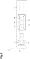
FIG. 2 is a plan view showing a configuration of a lateral flow test strip. -
FIG. 3 is a schematic diagram showing a sample determination example when no foreign substance adheres to a detection area. -
FIG. 4 is a schematic diagram showing a sample determination example when a foreign substance adheres to the detection area. -
FIG. 5 is a schematic diagram showing a sample determination example of this embodiment. -
FIG. 6 is a flowchart showing an overall operation of the optical measurement device. -
FIG. 7 is a flowchart showing a sample determination step. - Hereinafter, a preferred embodiment of an optical measurement device and an optical measurement method according to an aspect of the present invention will be described in detail with reference to the drawings.
-
FIG. 1 is a diagram showing an embodiment of the optical measurement device. Anoptical measurement device 1 shown in the same drawing is a device which determines the reactivity of an antibody-antigen reaction or the like in a sample dropped on a lateral flow test strip K by measuring the coloration of a test line TL of the lateral flow test strip K. - As shown in
FIG. 1 , theoptical measurement device 1 includes an optical head (measurement unit) 2 which emits measurement light and measures reflection light, a placement plate which places the lateral flow test strip K thereon, and a drive mechanism (not shown) which relatively moves the placement plate with respect to theoptical head 2. Further, theoptical measurement device 1 includes a control unit (measurement unit) 3 which controls theoptical head 2, adetermination unit 4 which makes a determination on the lateral flow test strip K on the basis of the measurement result of the reflection light, and adisplay unit 5 which displays a determination result of thedetermination unit 4 as functional elements. These functional elements are realized by, for example, a computer system including a storage device such as a CPU, a RAM, and a ROM, an input device such as a keyboard and a mouse, and an auxiliary storage device such as a hard disk. - The lateral flow test strip K includes, as shown in
FIG. 2 , acasing 11 which has a rectangular shape in the plan view and atest strip body 12 which is held inside the casing. Thecasing 11 is provided with asample application window 13 which drops a sample to one end portion of thetest strip body 12 and anobservation window 14 which exposes the substantially center portion of thetest strip body 12 along the long side thereof. - The
test strip body 12 is formed in a rectangular shape by, for example, a nitrocellulose membrane or a filter paper. Thetest strip body 12 includes asample application portion 15 which is provided at a position corresponding to thesample application window 13 and adetection area 16 which is provided at a position corresponding to theobservation window 14. In thetest strip body 12, the sample developing direction is the direction from thesample application portion 15 to thedetection area 16. - The
detection area 16 is provided with the test line TL for determining the test result and a control line CL for determining whether or not the test is performed effectively in order from the front side of the sample developing direction at a predetermined interval. Both the test line TL and the control line CL are provided in a band shape in a direction intersecting the sample developing direction. - The sample is dropped from the
sample application window 13 onto thesample application portion 15. The measurement target substance in the sample binds to a labeling substance such as gold colloid contained in a reagent and develops over time in the long side direction of thetest strip body 12 together with the complex of the measurement target substance and the labeling substance in the sample and the unreacted labeling substance. When the sample reaches thedetection area 16 as the sample is developed, the measurement target substance in the sample specifically reacts with the binding substance fixed to the test line TL and the control line CL and a line-shaped pattern (coloration line) colored by the labeling substance is formed. The coloration line can be observed through theobservation window 14. - The reaction of the reagent proceeds over time after the sample is dropped onto the lateral flow test strip K. The reagent reaction usually continues to proceed unless the sample flowing with the reagent dries and sticks to the lateral flow test strip K. Thus, the coloration of the test line TL changes with time.
- The
optical head 2 includes, as shown inFIG. 1 , alight emitting element 21, alight detection element 22, a luminousflux shaping member 23, and alens 24. As thelight emitting element 21, for example, a semiconductor light emitting element called a light emitting diode (LED) is used. As thelight detection element 22, for example, a semiconductor light detection element called a silicon (Si) photodiode is used. Thelight emitting element 21 emits measurement light toward thetest strip body 12. The optical axis of thelight emitting element 21 is substantially perpendicular to the surface of the lateral flow test strip K. Thelight detection element 22 outputs an output signal corresponding to the intensity of the reflection light from thetest strip body 12 to thedetermination unit 4. The optical axis of thelight detection element 22 is inclined with respect to the optical axis of thelight emitting element 21. - The luminous
flux shaping member 23 is a plate-shaped member that shapes measurement light emitted from thelight emitting element 21. Aslit 23a extending in the same direction as those of the test line TL and the control line CL is provided at the center portion of the luminousflux shaping member 23. When the measurement light emitted from thelight emitting element 21 passes through theslit 23a, the measurement light is shaped to have a band-shaped luminous flux cross-section extending in the same direction as those of the test line TL and the control line CL. Further, thelens 24 is disposed on the optical axis of the measurement light emitted from thelight emitting element 21. Thelens 24 forms an image of the measurement light having passed through the luminousflux shaping member 23 on thetest strip body 12. - The
control unit 3 is a part that controls the drive of the placement plate by the drive mechanism, controls the on/off state of the measurement light by thelight emitting element 21, and processes the output signal of thelight detection element 22. Thecontrol unit 3 drives the placement plate in the long side direction of the lateral flow test strip K with respect to theoptical head 2. Accordingly, thedetection area 16 of the lateral flow test strip K is scanned by the measurement light. The time required for one scan is sufficiently shorter than the measurement interval in the interval measurement described later. - The
determination unit 4 is a part that makes a determination on the sample from the reaction between the measurement target substance in the sample and the binding substance. Thedetermination unit 4 acquires the reflection light intensity on the basis of the output signal from thelight detection element 22 and calculates the absorbance measurement value from the reflection light intensity. Thedetermination unit 4 determines whether or not the sample held by the lateral flow test strip K is positive or negative on the basis of the comparison between the measurement value and the first threshold value set in advance. Thedetermination unit 4 outputs information indicating a determination result to thedisplay unit 5 and thedisplay unit 5 displays the determination result on the basis of the information received from thedetermination unit 4. -
FIG. 3 is a schematic diagram showing an example of a behavior of the measurement value. In the same drawing, the horizontal axis indicates the time, the vertical axis indicates the measurement value (absorbance), and the first threshold value is indicated by the dashed line. Here, the first threshold value used to determine whether or not the sample is positive or negative is constant over the entire measurement period. When the sample is positive, for example, as shown inFIG. 3(a) , the measurement value gradually increases as the measurement period elapses and the measurement value exceeds the first threshold value at any point from the start to the end of measurement. On the other hand, when the sample is negative, for example, as shown inFIG. 3(b) , the measurement value does not increase as the measurement period elapses and the measurement value becomes the first threshold value or less over the entire measurement period. - Incidentally, in the inspection using the
optical measurement device 1, the adhesion of the foreign substance to thedetection area 16 of the lateral flow test strip K becomes a problem. As such a foreign substance, for example, powder of a constituent substance of the lateral flow test strip K is assumed. If such a foreign substance is transparent or white, it may be difficult to visually determine the presence or absence of adhesion. When the coloration state of the test line is optically read by using the lateral flow test strip K to which the foreign substance adheres, it is conceivable that the measurement value exceeds the first threshold value caused by the adhesion of the foreign substance and an originally negative sample is determined as positive. - When the foreign substance adheres to the
detection area 16 of the lateral flow test strip K, the measurement value caused by the adhesion of the foreign substance tends to have a constant value over the entire measurement period. Therefore, the measurement value may be a value obtained by adding the value caused by the adhesion of the foreign substance to the value caused by the reactivity between the measurement target substance in the sample and the binding substance. When the foreign substance adheres to thedetection area 16 of the lateral flow test strip K and the sample is positive, for example, as shown inFIG. 4(a) , the measurement value exceeds the first threshold value at the measurement start time point and the measurement value gradually increases as the measurement period elapses. In this case, since the measurement value exceeds the first threshold value over the entire measurement period, thedetermination unit 4 determines that the sample is positive. Thus, the adhesion of the foreign substance does not affect the sample determination result by thedetermination unit 4. - On the other hand, when the foreign substance adheres to the
detection area 16 of the lateral flow test strip K and the sample is negative, for example, as shown inFIG. 4(b) , the measurement value becomes a constant value exceeding the first threshold value over the entire measurement period. In this case, since the measurement value exceeds the first threshold value over the entire measurement period, thedetermination unit 4 determines that the sample is positive despite the fact that the sample is originally negative. Thus, the adhesion of the foreign substance affects the sample determination result by thedetermination unit 4. - On the other hand, the
determination unit 4 of theoptical measurement device 1 calculates the difference value between the initial measurement value and the latter measurement value when the measurement value exceeds the first threshold value. Thedetermination unit 4 holds the second threshold value set in advance for the difference value. Thedetermination unit 4 determines that the sample is positive when the difference value exceeds the second threshold value set in advance. Thedetermination unit 4 determines that the sample is negative even when the measurement value exceeds the first threshold value when the difference value is the second threshold value or less. - The
determination unit 4 may be configured to calculate the difference value when the measurement value exceeds the first threshold value at the reaction completion time point of the lateral flow test strip K or may be configured to calculate the difference value at a time point at which the measurement value exceeds the first threshold value (measurement times). In the description below, an embodiment is shown in which thedetermination unit 4 calculates the difference value when the measurement value exceeds the first threshold value at the reaction completion time point of the lateral flow test strip K. -
FIG. 5 is a schematic diagram showing a sample determination example of this embodiment. In the example of the same drawing, similarly toFIGS. 3 and4 , the horizontal axis indicates the time, the vertical axis indicates the measurement value (absorbance), and the first threshold value is indicated by the dashed line. In the embodiment ofFIG. 5 , the first threshold value used to determine whether or not the sample is positive or negative is set to gradually decrease as the measurement period elapses. In this case, thedetermination unit 4 calculates the difference value when the measurement value exceeds the first threshold value and the initial measurement value exceeds the first threshold value at the latter measurement. Here, the initial measurement value is set as the measurement value at the measurement start time point and the latter measurement value is set as the measurement value at the reaction completion time point. The reaction completion time point is, for example, a time point at which a predetermined time for determining negative elapses. Further, the first threshold value at the latter measurement is set as the first threshold value (Va) at the measurement end time point. - The graph A of
FIG. 5(a) shows a behavior of the measurement value when the foreign substance does not adhere to thedetection area 16 of the lateral flow test strip K and the sample is positive. In the graph A, the measurement value is the first threshold value or less at the initial measurement and the measurement value exceeds the first threshold value at the latter measurement. Further, in the graph A, the initial measurement value is the first threshold value Va or less at the measurement end time. Thus, thedetermination unit 4 does not calculate the difference value and determines that the sample is positive. - The graph B of
FIG. 5(a) shows a behavior of the measurement value when the foreign substance adheres to thedetection area 16 of the lateral flow test strip K and the sample is positive. In the graph B, the measurement value is the first threshold value or less at the initial measurement, but the measurement value exceeds the first threshold value at the latter measurement. Further, in the graph B, the initial measurement value exceeds the first threshold value Va at the latter measurement. Therefore, thedetermination unit 4 calculates a difference value Db between the initial measurement value and the latter measurement value. In the graph B, since the difference value is sufficiently larger than the second threshold value (not shown), thedetermination unit 4 determines that the sample is positive. - The graph C of
FIG. 5(b) shows a behavior of the measurement value when the foreign substance does not adhere to thedetection area 16 of the lateral flow test strip K and the sample is negative. In the graph C, the measurement value is the first threshold value or less over the entire measurement period. Thus, thedetermination unit 4 determines that the sample is negative. - The graph D of
FIG. 5(b) shows a behavior of the measurement value when the foreign substance adheres to thedetection area 16 of the lateral flow test strip K and the sample is negative. In the graph D, the measurement value is the first threshold value or less at the initial measurement, but the measurement value exceeds the first threshold value at the latter measurement. Further, in the graph D, the initial measurement value exceeds the first threshold value Va at the latter measurement. Therefore, thedetermination unit 4 calculates a difference value Dd between the initial measurement value and the latter measurement value. In the graph D, since the difference value is sufficiently smaller than the second threshold value (not shown), thedetermination unit 4 determines that the sample is negative. - Next, the operation of the
optical measurement device 1 will be described. -
FIG. 6 is a flowchart showing an overall operation of the optical measurement device. As shown in the same drawing, the measurement step by theoptical measurement device 1 includes a pre-measurement and an interval measurement. First, the lateral flow test strip K is set to the placement plate of the optical measurement device 1 (step S01). A measurer drops a sample onto thesample application window 13 of the lateral flow test strip K, for example, immediately before the placement on the placement plate. When a start operation (an operation of pressing a start button or the like) is input after the lateral flow test strip K is placed on the placement plate, the measurement of the lateral flow test strip K is started and the pre-measurement is performed (step S02). - In the pre-measurement, in order to check the reaction of the lateral flow test strip K to the control line CL at the initial measurement, the coloration of the control line CL is determined by the comparison between the measurement value of the light obtained from the control line CL and the threshold value set in advance. Based on this determination, it is checked whether or not the lateral flow test strip K set on the placement plate is in an appropriate state for measurement.
- After the pre-measurement is performed, the interval measurement is performed (step S03). The interval measurement is a measurement in which the light obtained from the test line TL is measured at predetermined time intervals. The interval measurement may be continued until the reaction completion time of the reagent in the lateral flow test strip K or may be ended at a time point at which a determination is made before the reaction completion time. The reaction completion time is set in advance for each lateral flow test strip K (the combination of the material of the
test strip body 12 and the type of reagent). As an example, when the reaction completion time is ten minutes, the interval measurement is performed up to ten times at one minute interval. In this case, the tenth interval measurement is a regular measurement corresponding to the reaction completion time. At the reaction completion time point, it is determined whether or not the sample is positive or negative on the basis of the comparison between the measurement value of the light obtained from the test line TL and the threshold value set in advance. -
FIG. 7 is a flowchart showing a sample determination step. In this embodiment, the sample determination step is performed after the reaction of the lateral flow test strip K is completed. As shown in the same drawing, in the sample determination step, it is first determined whether or not the measurement value exceeds the first threshold value (step S 11). The routine proceeds to step S16 and when the measurement value is the first threshold value or less, the sample is determined as negative. When the measurement value exceeds the first threshold value, it is determined whether or not the initial measurement value exceeds the first threshold value at the latter measurement (step S12). When the initial measurement value is the first threshold value or less at the latter measurement, the routine proceeds to stepS 15 and the sample is determined as positive. - When the initial measurement value exceeds the first threshold value at the latter measurement, the difference value between the initial measurement value and the latter measurement value is calculated (step S13). After the calculation of the difference value, it is determined whether or not the difference value exceeds the second threshold value (step S14). When the difference value exceeds the second threshold value, it is determined that the sample is positive (step S15). When the difference value is the second threshold value or less, it is determined that the sample is negative (step S16).
- As described above, in the
optical measurement device 1, it is determined whether or not the sample held by the lateral flow test strip K is negative or positive on the basis of the comparison between the measurement value of the light obtained from thedetection area 16 by the emission of the measurement light and the first threshold value set in advance. In thisoptical measurement device 1, the difference value between the initial measurement value and the latter measurement value is calculated when the measurement value exceeds the first threshold value. It is possible to distinguish whether or not the measurement value exceeding the first threshold value is caused by the adhesion of the foreign substance by comparing the difference value with the second threshold value. Thus, it is possible to ensure the sample determination accuracy even when the foreign substance adheres to the lateral flow test strip K. - In this embodiment, the first threshold value is set to gradually decrease as the measurement period elapses and the
determination unit 4 calculates the difference value when the measurement value exceeds the first threshold value and the initial measurement value exceeds the first threshold value at the latter measurement. It is possible to improve the sample determination accuracy by setting the first threshold value to gradually decrease as the measurement period elapses. For example, it is possible to prevent the sample from being determined as positive by mistake when the coloration of the test line TL is temporarily increased due to the influence of the labeling substance unrelated to the test line TL (the labeling substance unrelated to the reaction related to the coloration of the test line TL) immediately after the sample is dropped. Further, it is possible to accurately distinguish whether or not the measurement value exceeding the first threshold value is caused by the adhesion of the foreign substance even when the first threshold value is set to gradually decrease as the measurement period elapses by comparing the initial measurement value with the first threshold value at the latter measurement. - Further, in this embodiment, the
determination unit 4 calculates the difference value when the measurement value exceeds the first threshold value at the reaction completion time point of the lateral flow test strip K. In this way, it is possible to more accurately distinguish whether or not the measurement value exceeding the first threshold value is caused by the adhesion of the foreign substance by calculating the difference value when the measurement value exceeds the first threshold value after the reaction of the lateral flow test strip K is completed. - The present disclosure is not limited to the above-described embodiment. For example, in the above-described embodiment, the first threshold value is set to gradually decrease as the measurement period elapses, but the threshold value may be set to a constant value over the entire measurement period. Further, in the above-described embodiment, the lateral flow test strip K provided with one test line TL is illustrated, but a plurality of the test lines TL may be provided in the lateral flow test strip K. Further, in the above-described embodiment, both the measurement step and the determination step are performed by the
optical measurement device 1. However, the optical measurement device may perform only the measurement step and the measurer may perform the determination step on the basis of the acquired measurement value. - Further, in the above-described embodiment, the absorbance calculated from the reflection light intensity of the measurement light is the measurement value, but as the measurement value, any other measurement value may be used as long as the measurement value is obtained on the basis of the light obtained from the
detection area 16 by the emission of the measurement light. For example, an embodiment may be used in which the intensity of fluorescence excited by the emission of measurement light is used as a measurement value. - 1: optical measurement device, 2: optical head (measurement unit), 3: control unit (measurement unit), 4: determination unit, 16: detection area, K: lateral flow test strip.
Claims (6)
- An optical measurement device comprising:a measurement unit which emits measurement light to a detection area of a lateral flow test strip and measures light obtained from the detection area by the emission of the measurement light for a predetermined period; anda determination unit which determines whether or not a sample held in the lateral flow test strip is negative or positive on the basis of a comparison between a measurement value obtained by the measurement unit and a first threshold value set in advance,wherein the determination unit calculates a difference value between an initial measurement value and a latter measurement value when the measurement value exceeds the first threshold value after the sample is held by the lateral flow test strip, determines that the sample is positive when the difference value exceeds a second threshold value set in advance, and determines that the sample is negative when the difference value is the second threshold value or less.
- The optical measurement device according to claim 1,wherein the first threshold value is set to gradually decrease as a measurement period elapses, andwherein the determination unit calculates the difference value when the measurement value exceeds the first threshold value and the initial measurement value exceeds the first threshold value at the latter measurement.
- The optical measurement device according to claim 1 or 2,
wherein the determination unit calculates the difference value when the measurement value exceeds the first threshold value at a reaction completion time point of the lateral flow test strip. - An optical measurement method comprising:a measurement step of emitting measurement light to a detection area of a lateral flow test strip and measuring light obtained from the detection area by the emission of the measurement light for a predetermined period; anda determination step of determining whether or not a sample held by the lateral flow test strip is negative or positive on the basis of a comparison between a measurement value obtained by the measurement step and a first threshold value set in advance,wherein the determination step calculates a difference value between the initial measurement value and the latter measurement value when the measurement value exceeds the first threshold value after the sample is held by the lateral flow test strip, determines that the sample is positive when the difference value exceeds a second threshold value set in advance, and determines that the sample is negative when the difference value is the second threshold value or less.
- The optical measurement method according to claim 4,wherein the first threshold value is set to gradually decrease as a measurement period elapses, andwherein the determination step calculates the difference value when the measurement value exceeds the first threshold value and the initial measurement value exceeds the first threshold value at the latter measurement.
- The optical measurement method according to claim 4 or 5,
wherein the determination step calculates the difference value when the measurement value exceeds the first threshold value at a reaction completion time point of the lateral flow test strip.
Applications Claiming Priority (2)
| Application Number | Priority Date | Filing Date | Title |
|---|---|---|---|
| JP2020052380A JP7300414B2 (en) | 2020-03-24 | 2020-03-24 | Optical measuring device and optical measuring method |
| PCT/JP2021/012057 WO2021193660A1 (en) | 2020-03-24 | 2021-03-23 | Optical measurement device and optical measurement method |
Publications (3)
| Publication Number | Publication Date |
|---|---|
| EP4130738A1 true EP4130738A1 (en) | 2023-02-08 |
| EP4130738A4 EP4130738A4 (en) | 2024-04-24 |
| EP4130738B1 EP4130738B1 (en) | 2025-12-03 |
Family
ID=77886480
Family Applications (1)
| Application Number | Title | Priority Date | Filing Date |
|---|---|---|---|
| EP21774544.7A Active EP4130738B1 (en) | 2020-03-24 | 2021-03-23 | Optical measurement device and optical measurement method |
Country Status (5)
| Country | Link |
|---|---|
| US (1) | US12345628B2 (en) |
| EP (1) | EP4130738B1 (en) |
| JP (1) | JP7300414B2 (en) |
| CN (1) | CN115335699A (en) |
| WO (1) | WO2021193660A1 (en) |
Family Cites Families (14)
| Publication number | Priority date | Publication date | Assignee | Title |
|---|---|---|---|---|
| US9891217B2 (en) * | 2005-04-22 | 2018-02-13 | Alverix, Inc. | Assay test strips with multiple labels and reading same |
| US7625763B2 (en) * | 2006-09-11 | 2009-12-01 | Alverix, Inc. | Rapid diagnostic test systems and methods |
| JP4860489B2 (en) | 2007-01-09 | 2012-01-25 | 浜松ホトニクス株式会社 | Method for measuring immunochromatographic test strip |
| JP5184962B2 (en) | 2007-10-31 | 2013-04-17 | アークレイ株式会社 | Immunochromatography equipment |
| WO2009145250A1 (en) | 2008-05-29 | 2009-12-03 | アークレイ株式会社 | Immunoassay analyzer and immunoassay method |
| US9417235B2 (en) | 2008-11-20 | 2016-08-16 | Arkray, Inc. | Optical measurement apparatus |
| JP5244834B2 (en) | 2010-02-25 | 2013-07-24 | 富士フイルム株式会社 | Color measuring device and method |
| US8828329B2 (en) * | 2010-10-01 | 2014-09-09 | Church & Dwight, Co., Inc. | Electronic analyte assaying device |
| US9939385B2 (en) * | 2011-09-09 | 2018-04-10 | Church & Dwight Co., Inc. | Systems, methods, and test kits for analyte variation detection |
| EP2901151B1 (en) * | 2012-09-27 | 2018-05-16 | Ellume Pty Ltd. | Diagnostic devices and methods |
| TWI485391B (en) * | 2012-11-12 | 2015-05-21 | Taidoc Technology Corp | Electronic assay apparatus, method and kit thereof |
| US20140271362A1 (en) * | 2013-03-12 | 2014-09-18 | Robert J. Markovsky | Recognition test strips |
| CN108139331B (en) * | 2015-10-09 | 2021-03-16 | 浜松光子学株式会社 | Optical measuring device |
| AU2018295562A1 (en) | 2017-07-04 | 2020-01-16 | Ellume Limited | Methods and apparatus for sample analysis using lateral flow |
-
2020
- 2020-03-24 JP JP2020052380A patent/JP7300414B2/en active Active
-
2021
- 2021-03-23 CN CN202180022995.XA patent/CN115335699A/en active Pending
- 2021-03-23 US US17/912,578 patent/US12345628B2/en active Active
- 2021-03-23 EP EP21774544.7A patent/EP4130738B1/en active Active
- 2021-03-23 WO PCT/JP2021/012057 patent/WO2021193660A1/en not_active Ceased
Also Published As
| Publication number | Publication date |
|---|---|
| WO2021193660A1 (en) | 2021-09-30 |
| EP4130738B1 (en) | 2025-12-03 |
| JP7300414B2 (en) | 2023-06-29 |
| EP4130738A4 (en) | 2024-04-24 |
| CN115335699A (en) | 2022-11-11 |
| US12345628B2 (en) | 2025-07-01 |
| US20230136517A1 (en) | 2023-05-04 |
| JP2021152459A (en) | 2021-09-30 |
Similar Documents
| Publication | Publication Date | Title |
|---|---|---|
| US10921260B2 (en) | Optical measuring device | |
| EP2594919B1 (en) | Assay detection judgment apparatus and method | |
| CN101044402B (en) | Method for measuring dynamic internally calibrated true-value dose-response curves | |
| US12025617B2 (en) | Method of using differential measurement in two or more channels to improve sensitivity | |
| CN115038956A (en) | Chromatography inspection apparatus and control method thereof | |
| EP4130738B1 (en) | Optical measurement device and optical measurement method | |
| JP5244834B2 (en) | Color measuring device and method | |
| KR101701072B1 (en) | Method and device for determining sample application | |
| JPH10332582A (en) | Measuring apparatus for turbidity | |
| JP7617893B2 (en) | Component measuring device, component measuring device set, and information processing method | |
| US20190195842A1 (en) | Testing apparatus and control method thereof | |
| US20220034877A1 (en) | Diagnostic testing device and diagnostic testing method | |
| JPH1031011A (en) | Test strip analyzer and analysis method using test strip | |
| CN101772703B (en) | Assay method using biosensor | |
| JP7617896B2 (en) | Component measuring device, component measuring device set, and information processing method | |
| EP3889585A1 (en) | Reference cassette for fluorescence immunoassay diagnostic device | |
| WO2024185672A1 (en) | Test determination device and test determination method | |
| JPS62116204A (en) | Method and apparatus for measuring contact area | |
| KR20170113159A (en) | Ultrasensitive biomarker quantification method using photooxidation-induced amplification |
Legal Events
| Date | Code | Title | Description |
|---|---|---|---|
| STAA | Information on the status of an ep patent application or granted ep patent |
Free format text: STATUS: THE INTERNATIONAL PUBLICATION HAS BEEN MADE |
|
| PUAI | Public reference made under article 153(3) epc to a published international application that has entered the european phase |
Free format text: ORIGINAL CODE: 0009012 |
|
| STAA | Information on the status of an ep patent application or granted ep patent |
Free format text: STATUS: REQUEST FOR EXAMINATION WAS MADE |
|
| 17P | Request for examination filed |
Effective date: 20221012 |
|
| AK | Designated contracting states |
Kind code of ref document: A1 Designated state(s): AL AT BE BG CH CY CZ DE DK EE ES FI FR GB GR HR HU IE IS IT LI LT LU LV MC MK MT NL NO PL PT RO RS SE SI SK SM TR |
|
| DAV | Request for validation of the european patent (deleted) | ||
| DAX | Request for extension of the european patent (deleted) | ||
| A4 | Supplementary search report drawn up and despatched |
Effective date: 20240321 |
|
| RIC1 | Information provided on ipc code assigned before grant |
Ipc: G01N 21/78 20060101ALI20240315BHEP Ipc: G01N 21/84 20060101ALI20240315BHEP Ipc: G01N 21/27 20060101ALI20240315BHEP Ipc: G01N 33/543 20060101ALI20240315BHEP Ipc: G01N 33/483 20060101AFI20240315BHEP |
|
| GRAP | Despatch of communication of intention to grant a patent |
Free format text: ORIGINAL CODE: EPIDOSNIGR1 |
|
| STAA | Information on the status of an ep patent application or granted ep patent |
Free format text: STATUS: GRANT OF PATENT IS INTENDED |
|
| INTG | Intention to grant announced |
Effective date: 20250721 |
|
| GRAS | Grant fee paid |
Free format text: ORIGINAL CODE: EPIDOSNIGR3 |
|
| GRAA | (expected) grant |
Free format text: ORIGINAL CODE: 0009210 |
|
| STAA | Information on the status of an ep patent application or granted ep patent |
Free format text: STATUS: THE PATENT HAS BEEN GRANTED |
|
| AK | Designated contracting states |
Kind code of ref document: B1 Designated state(s): AL AT BE BG CH CY CZ DE DK EE ES FI FR GB GR HR HU IE IS IT LI LT LU LV MC MK MT NL NO PL PT RO RS SE SI SK SM TR |
|
| P01 | Opt-out of the competence of the unified patent court (upc) registered |
Free format text: CASE NUMBER: UPC_APP_0011339_4130738/2025 Effective date: 20251028 |
|
| REG | Reference to a national code |
Ref country code: CH Ref legal event code: F10 Free format text: ST27 STATUS EVENT CODE: U-0-0-F10-F00 (AS PROVIDED BY THE NATIONAL OFFICE) Effective date: 20251203 Ref country code: GB Ref legal event code: FG4D |
|
| REG | Reference to a national code |
Ref country code: DE Ref legal event code: R096 Ref document number: 602021043675 Country of ref document: DE |
|
| REG | Reference to a national code |
Ref country code: IE Ref legal event code: FG4D |
|
| REG | Reference to a national code |
Ref country code: NL Ref legal event code: MP Effective date: 20251203 |
|
| PGFP | Annual fee paid to national office [announced via postgrant information from national office to epo] |
Ref country code: GB Payment date: 20260202 Year of fee payment: 6 |
|
| PG25 | Lapsed in a contracting state [announced via postgrant information from national office to epo] |
Ref country code: ES Free format text: LAPSE BECAUSE OF FAILURE TO SUBMIT A TRANSLATION OF THE DESCRIPTION OR TO PAY THE FEE WITHIN THE PRESCRIBED TIME-LIMIT Effective date: 20251203 |
|
| REG | Reference to a national code |
Ref country code: LT Ref legal event code: MG9D |
|
| PG25 | Lapsed in a contracting state [announced via postgrant information from national office to epo] |
Ref country code: NO Free format text: LAPSE BECAUSE OF FAILURE TO SUBMIT A TRANSLATION OF THE DESCRIPTION OR TO PAY THE FEE WITHIN THE PRESCRIBED TIME-LIMIT Effective date: 20260303 |
|
| PGFP | Annual fee paid to national office [announced via postgrant information from national office to epo] |
Ref country code: DE Payment date: 20260128 Year of fee payment: 6 |
|
| PG25 | Lapsed in a contracting state [announced via postgrant information from national office to epo] |
Ref country code: FI Free format text: LAPSE BECAUSE OF FAILURE TO SUBMIT A TRANSLATION OF THE DESCRIPTION OR TO PAY THE FEE WITHIN THE PRESCRIBED TIME-LIMIT Effective date: 20251203 Ref country code: HR Free format text: LAPSE BECAUSE OF FAILURE TO SUBMIT A TRANSLATION OF THE DESCRIPTION OR TO PAY THE FEE WITHIN THE PRESCRIBED TIME-LIMIT Effective date: 20251203 |
|
| PG25 | Lapsed in a contracting state [announced via postgrant information from national office to epo] |
Ref country code: RS Free format text: LAPSE BECAUSE OF FAILURE TO SUBMIT A TRANSLATION OF THE DESCRIPTION OR TO PAY THE FEE WITHIN THE PRESCRIBED TIME-LIMIT Effective date: 20260303 |
|
| PGFP | Annual fee paid to national office [announced via postgrant information from national office to epo] |
Ref country code: FR Payment date: 20260209 Year of fee payment: 6 |
|
| PG25 | Lapsed in a contracting state [announced via postgrant information from national office to epo] |
Ref country code: PL Free format text: LAPSE BECAUSE OF FAILURE TO SUBMIT A TRANSLATION OF THE DESCRIPTION OR TO PAY THE FEE WITHIN THE PRESCRIBED TIME-LIMIT Effective date: 20251203 |
|
| PG25 | Lapsed in a contracting state [announced via postgrant information from national office to epo] |
Ref country code: LV Free format text: LAPSE BECAUSE OF FAILURE TO SUBMIT A TRANSLATION OF THE DESCRIPTION OR TO PAY THE FEE WITHIN THE PRESCRIBED TIME-LIMIT Effective date: 20251203 |
|
| PG25 | Lapsed in a contracting state [announced via postgrant information from national office to epo] |
Ref country code: BG Free format text: LAPSE BECAUSE OF FAILURE TO SUBMIT A TRANSLATION OF THE DESCRIPTION OR TO PAY THE FEE WITHIN THE PRESCRIBED TIME-LIMIT Effective date: 20251203 |