EP4130695A1 - Measurement device - Google Patents
Measurement device Download PDFInfo
- Publication number
- EP4130695A1 EP4130695A1 EP20926423.3A EP20926423A EP4130695A1 EP 4130695 A1 EP4130695 A1 EP 4130695A1 EP 20926423 A EP20926423 A EP 20926423A EP 4130695 A1 EP4130695 A1 EP 4130695A1
- Authority
- EP
- European Patent Office
- Prior art keywords
- strain
- measurement
- optical fiber
- temperature
- fiber sensor
- Prior art date
- Legal status (The legal status is an assumption and is not a legal conclusion. Google has not performed a legal analysis and makes no representation as to the accuracy of the status listed.)
- Withdrawn
Links
Images



Classifications
-
- G—PHYSICS
- G01—MEASURING; TESTING
- G01K—MEASURING TEMPERATURE; MEASURING QUANTITY OF HEAT; THERMALLY-SENSITIVE ELEMENTS NOT OTHERWISE PROVIDED FOR
- G01K11/00—Measuring temperature based upon physical or chemical changes not covered by groups G01K3/00, G01K5/00, G01K7/00 or G01K9/00
- G01K11/32—Measuring temperature based upon physical or chemical changes not covered by groups G01K3/00, G01K5/00, G01K7/00 or G01K9/00 using changes in transmittance, scattering or luminescence in optical fibres
- G01K11/3206—Measuring temperature based upon physical or chemical changes not covered by groups G01K3/00, G01K5/00, G01K7/00 or G01K9/00 using changes in transmittance, scattering or luminescence in optical fibres at discrete locations in the fibre, e.g. using Bragg scattering
-
- G—PHYSICS
- G01—MEASURING; TESTING
- G01B—MEASURING LENGTH, THICKNESS OR SIMILAR LINEAR DIMENSIONS; MEASURING ANGLES; MEASURING AREAS; MEASURING IRREGULARITIES OF SURFACES OR CONTOURS
- G01B11/00—Measuring arrangements characterised by the use of optical techniques
- G01B11/16—Measuring arrangements characterised by the use of optical techniques for measuring the deformation in a solid, e.g. optical strain gauge
-
- G—PHYSICS
- G01—MEASURING; TESTING
- G01B—MEASURING LENGTH, THICKNESS OR SIMILAR LINEAR DIMENSIONS; MEASURING ANGLES; MEASURING AREAS; MEASURING IRREGULARITIES OF SURFACES OR CONTOURS
- G01B11/00—Measuring arrangements characterised by the use of optical techniques
- G01B11/16—Measuring arrangements characterised by the use of optical techniques for measuring the deformation in a solid, e.g. optical strain gauge
- G01B11/165—Measuring arrangements characterised by the use of optical techniques for measuring the deformation in a solid, e.g. optical strain gauge by means of a grating deformed by the object
-
- G—PHYSICS
- G01—MEASURING; TESTING
- G01B—MEASURING LENGTH, THICKNESS OR SIMILAR LINEAR DIMENSIONS; MEASURING ANGLES; MEASURING AREAS; MEASURING IRREGULARITIES OF SURFACES OR CONTOURS
- G01B5/00—Measuring arrangements characterised by the use of mechanical techniques
- G01B5/0011—Arrangements for eliminating or compensation of measuring errors due to temperature or weight
- G01B5/0014—Arrangements for eliminating or compensation of measuring errors due to temperature or weight due to temperature
-
- G—PHYSICS
- G01—MEASURING; TESTING
- G01K—MEASURING TEMPERATURE; MEASURING QUANTITY OF HEAT; THERMALLY-SENSITIVE ELEMENTS NOT OTHERWISE PROVIDED FOR
- G01K1/00—Details of thermometers not specially adapted for particular types of thermometer
- G01K1/14—Supports; Fastening devices; Arrangements for mounting thermometers in particular locations
-
- G—PHYSICS
- G01—MEASURING; TESTING
- G01K—MEASURING TEMPERATURE; MEASURING QUANTITY OF HEAT; THERMALLY-SENSITIVE ELEMENTS NOT OTHERWISE PROVIDED FOR
- G01K1/00—Details of thermometers not specially adapted for particular types of thermometer
- G01K1/14—Supports; Fastening devices; Arrangements for mounting thermometers in particular locations
- G01K1/143—Supports; Fastening devices; Arrangements for mounting thermometers in particular locations for measuring surface temperatures
-
- G—PHYSICS
- G01—MEASURING; TESTING
- G01L—MEASURING FORCE, STRESS, TORQUE, WORK, MECHANICAL POWER, MECHANICAL EFFICIENCY, OR FLUID PRESSURE
- G01L1/00—Measuring force or stress, in general
- G01L1/24—Measuring force or stress, in general by measuring variations of optical properties of material when it is stressed, e.g. by photoelastic stress analysis using infrared, visible light, ultraviolet
- G01L1/242—Measuring force or stress, in general by measuring variations of optical properties of material when it is stressed, e.g. by photoelastic stress analysis using infrared, visible light, ultraviolet the material being an optical fibre
- G01L1/246—Measuring force or stress, in general by measuring variations of optical properties of material when it is stressed, e.g. by photoelastic stress analysis using infrared, visible light, ultraviolet the material being an optical fibre using integrated gratings, e.g. Bragg gratings
Definitions
- the FBG sensor portion 12 is employed when measuring a temperature with using a relationship between a Bragg wavelength and a temperature, and when measuring a strain with using a relationship between the Bragg wavelength and the strain.
- the FBG sensor portion 12 is arranged inside the core 11.
- Examples of a material that forms the cover portion 14 include, for example, an acrylate resin and a polyimide resin.
- the strain portion 25 is a plate spring.
- the strain portion 25 which is a plate spring is attached to the moving portion 24 such that a distal end portion 251 is pressed against the cam portion 22 and that a base portion 252 through to a middle portion 253 are in contact with the measurement target 110.
- a strain of the plate spring near the distal end portion 251 is changed by the cam portion 22.
- the distal end 222 of the attaching tool 221 is formed into a hook-like shape.
- the attaching tool 221 draws the hook-like distal end 222 with a spring 223 toward a handle 224 side.
- the attaching device 21 can be attached either to a large measurement target 110 as illustrated on a left side of Fig. 9 , or to a small measurement target 110 as illustrated on a right side of Fig. 9 .
- a lever 225 may be pulled toward the measurement target 110 side to open wide the hook-like distal end 222, and the measurement target 110 may be pinched between the hook-like distal end 222 and the handle 224.
- the optical fiber sensor 10 provided with the FBG sensor portion 12 is employed.
- the optical fiber sensor 10 is not limited to one provided with an FBG sensor portion 12, but can be another multi-point optical fiber sensor or a distributed optical fiber.
Landscapes
- Physics & Mathematics (AREA)
- General Physics & Mathematics (AREA)
- Length Measuring Devices By Optical Means (AREA)
- Optical Transform (AREA)
- Measuring Temperature Or Quantity Of Heat (AREA)
Abstract
Description
- The present disclosure relates to a technique of measuring a temperature and strain of a measurement target using an optical fiber sensor.
- Patent Literature 1 describes a measurement method with which a multi-point optical fiber sensor which utilizes Fiber Bragg Grating (FBG) is covered with a protective material made of fiber, a resultant structure is integrated by solidification with a resin, and then the integrated structure is fixed to a measurement target such as a pipe with using a fastening band. According to this measurement method, since the optical fiber sensor is firmly fixed to the measurement target, the optical fiber sensor can follow behavior of the measurement target well and measure the temperature and strain accurately.
- Patent Literature 1:
JP 2013-104700 A - According to the measurement method described in Patent Literature 1, it is necessary to form the optical fiber and the protective material into a shape of the measurement target in advance while positioning the sensor. Therefore, it is difficult to mount the resultant optical fiber sensor on a measurement target having a complicated shape such as a pipe in a refrigeration cycle or the like.
- An objective of the present invention is to make it possible to easily detect a temperature and strain of even a measurement target having a complicated shape with an optical fiber sensor.
- A measurement device according to the present disclosure includes:
- a cam portion attached to a first position on a measurement target;
- a moving portion attached to a second position on the measurement target and movable with respect to the cam portion in an expanding/contracting direction of the measurement target;
- a strain portion attached to the moving portion so as to fit along the measurement target, and pressed against the cam portion, the strain portion having a strain that changes when the measurement target expands or contracts and the moving portion moves accordingly;
- a temperature-detection optical fiber sensor having a temperature measurement portion for measuring a temperature and attached to the strain portion; and
- a strain-detection optical fiber sensor having a strain measurement portion for measuring a strain and attached to the strain portion.
- In the present disclosure, an optical fiber sensor is attached to a strain portion which is attached to a moving portion movable in an expanding/contracting direction of a measurement target and which is pressed against a cam portion. As a result, a temperature and strain of even a measurement target having a complicated shape can be easily detected with the optical fiber sensor.
-
-
Fig. 1 is a configuration diagram of anoptical fiber sensor 10 according to Embodiment 1. -
Fig. 2 is an explanatory diagram of anFBG sensor portion 12 according to Embodiment 1. -
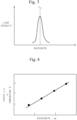
Fig. 3 is a graph illustrating characteristics of a reflection spectrum obtained in theFBG sensor portion 12 according to Embodiment 1. -
Fig. 4 is a diagram illustrating an example of a calibration curve of a temperature and wavelength according to Embodiment 1, and an example of a calibration curve of a strain and wavelength according to Embodiment 1. -
Fig. 5 is a configuration diagram of ameasurement system 100 according to Embodiment 1. -
Fig. 6 is a configuration diagram of ameasurement device 20 according to Embodiment 1. -
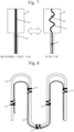
Fig. 7 is an explanatory diagram of how to arrange theoptical fiber sensor 10 on astrain portion 25 according to Embodiment 1. -
Fig. 8 is an explanatory diagram of how to attach themeasurement device 20 according to Embodiment 1. -
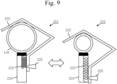
Fig. 9 is an explanatory diagram of an attachingtool 221 and an attachingtool 241 according to Embodiment 1. -
Fig. 10 is an explanatory diagram of operations of themeasurement device 20 according to Embodiment 1. - A configuration of an
optical fiber sensor 10 according to Embodiment 1 will be described with referring toFigs. 1 to 4 . - Optical fiber sensors include multi-point optical fiber sensors and distributed optical fiber sensors. A multi-point optical fiber sensor can perform measurement at a plurality of points which are set on one optical fiber. A distributed optical fiber sensor can perform measurement with one optical fiber consecutively. Measurement with an optical fiber uses light having a wide-band frequency or scattered light. Examples of the scattered light include, for example, Rayleigh scattered light, Brillouin scattered light, and Raman scattered light.
- In Embodiment 1, the
optical fiber sensor 10 is an optical fiber sensor in which Fiber Bragg Gratings (FBG) are used as a sensor portion. - As illustrated in
Fig. 1 , theoptical fiber sensor 10 is provided with acore 11, anFBG sensor portion 12 formed in thecore 11, acladding 13 which covers a circumferential surface of the core, and acover portion 14 which covers a circumferential surface of thecladding 13. - The
FBG sensor portion 12 is employed when measuring a temperature with using a relationship between a Bragg wavelength and a temperature, and when measuring a strain with using a relationship between the Bragg wavelength and the strain. TheFBG sensor portion 12 is arranged inside thecore 11. Examples of a material that forms thecover portion 14 include, for example, an acrylate resin and a polyimide resin. - A cover-removed
portion 15 where the circumferential surface of thecladding 13 is exposed is formed in thecover portion 14. The cover-removedportion 15 is formed in a region of thecover portion 14 that corresponds to theFBG sensor portion 12, in a direction of diameter of theoptical fiber sensor 10. Therefore, that portion of theoptical fiber sensor 10 where theFBG sensor portion 12 is arranged has a smaller size in the direction of diameter as compared to other portions of theoptical fiber sensor 10. - An example of a size in the direction of diameter of a portion of the
optical fiber sensor 10 where thecover portion 14 is present is 250 µm (micrometers). An example of a size in the direction of diameter of thecladding 13 is 125 µm. An example of a size in the direction of diameter of thecore 11 is 10 µm. TheFBG sensor portion 12 is arranged to extend in a range of about 5 mm (millimeters) of thecore 11 in a longitudinal direction of theoptical fiber sensor 10. - As illustrated in
Fig. 2 , theFBG sensor portion 12 is a modulating portion formed in thecore 11 to have a periodic inflection index. Hence, a steep reflection spectrum characteristic can be obtained in theFBG sensor portion 12. In theFBG sensor portion 12, a refractive index of thecore 11 changes with a period A. - As illustrated in
Fig. 3 , a steep reflection spectrum is obtained in theFBG sensor portion 12. A light intensity is maximum at a central wavelength of the obtained refection spectrum. InFig. 3 , the central wavelength of the reflection spectrum is Bragg wavelength λb. - A relationship among the Bragg wavelength λb, the period A, and a refractive index n is expressed by following Formula 1.

- The refractive index n changes depending on a temperature of an optical fiber. The period A changes depending on the temperature and strain of the optical fiber.
- Therefore, when measuring a temperature, a strain of the measurement target should not be transmitted to the optical fiber, and a relationship between a change in Bragg wavelength λb and a change in temperature is measured in advance as illustrated in
Fig. 4 , so that a temperature of a measurement target can be measured. On the other hand, when measuring a strain, a temperature of a vicinity of the measurement target is obtained, and a wavelength change caused by the temperature is subtracted from the change in Bragg wavelength λb. As a result, a change in Bragg wavelength λb that corresponds to only a change in strain can be obtained, so that the strain of the measurement target can be measured. - A configuration of a
measurement system 100 according to Embodiment 1 will be described with referring toFig. 5 . - The
measurement system 100 is provided with ameasurement device 20 having theoptical fiber sensor 10, anoptical circulator 30, an Amplified Spontaneous Emission (ASE)light source 40, and aspectrum analyzer 50. - The
measurement device 20 is provided with theoptical fiber sensor 10 and attaches theoptical fiber sensor 10 to a measurement target. Theoptical circulator 30 is connected to a longitudinal-direction end portion of theoptical fiber sensor 10. Theoptical circulator 30 transforms an optical path. The ASElight source 40 emits light having a frequency in a relatively wide band. The ASElight source 40 is connected to theoptical circulator 30. Light emitted from the ASElight source 40 enters theoptical circulator 30. Thespectrum analyzer 50 is a wavelength measurement device. Thespectrum analyzer 50 is connected to theoptical circulator 30. Light enters thespectrum analyzer 50 via theoptical circulator 30. - The
measurement system 100 converts the Bragg wavelength λb obtained with thespectrum analyzer 50 into a temperature and a strain. Hence, the temperature and strain of the measurement target are identified. - A configuration of the
measurement device 20 according to Embodiment 1 will be described with referring toFigs. 6 through 9 . - The
measurement device 20 is provided with theoptical fiber sensor 10 and an attachingdevice 21. The attachingdevice 21 is a device that attaches theoptical fiber sensor 10 to ameasurement target 110. The attachingdevice 21 is provided with acam portion 22, arail portion 23, a movingportion 24, and astrain portion 25. - In Embodiment 1, the
measurement target 110 is a pipe employed in an apparatus such as a refrigeration cycle and an artificial satellite. Themeasurement target 110 is not limited to a pipe but can be anything that is a target whose temperature and strain are to be measured. In Embodiment 1, there is a possibility that a strain occurs in themeasurement target 110 in the longitudinal direction, that is, there is a possibility that themeasurement target 110 expands and contracts in the longitudinal direction. - The
cam portion 22 is attached to afirst position 111 on themeasurement target 110. InFig. 6 , thecam portion 22 is attached to thefirst position 111 by an attachingtool 221. As that surface of thecam portion 22 against which thestrain portion 25 to be described later is pressed separates from themeasurement target 110, thecam portion 22 moves away from the movingportion 24. In Embodiment 1, the surface against which thestrain portion 25 is pressed is a curved surface. - The
rail portion 23 is attached to thecam portion 22 so as to be parallel to the longitudinal direction of themeasurement target 110. - The moving
portion 24 is attached to asecond position 112 on themeasurement target 110, and is attached to therail portion 23 so as to be movable along therail portion 23. As being attached be movable along therail portion 23, the movingportion 24 is movable with respect to thecam portion 22 in an expanding/contracting direction of the measurement target. - In
Fig. 6 , the movingportion 24 is attached to thesecond position 112 by an attachingtool 241. InFig. 6 , the movingportion 24 is attached to therail portion 23 via arotating portion 242. InFig. 6 , when themeasurement target 110 expands or contracts and therotating portion 242 rotates accordingly, the movingportion 24 moves along therail portion 23. The movingportion 24 may have another structure such that it moves by sliding as being guided by therail portion 23. - The
strain portion 25 is attached to the movingportion 24 so as to fit along themeasurement target 110, and is pressed against thecam portion 22. A strain of thestrain portion 25 changes when themeasurement target 110 expands or contracts and the movingportion 24 moves accordingly. - In Embodiment 1, the
strain portion 25 is a plate spring. In Embodiment 1, thestrain portion 25 which is a plate spring is attached to the movingportion 24 such that adistal end portion 251 is pressed against thecam portion 22 and that abase portion 252 through to amiddle portion 253 are in contact with themeasurement target 110. Hence, when themeasurement target 110 expands or contracts and the movingportion 24 moves accordingly, a strain of the plate spring near thedistal end portion 251 is changed by thecam portion 22. - In Embodiment 1, the
optical fiber sensor 10 is formed of one optical fiber. Theoptical fiber sensor 10 has two types ofFBG sensor portions 12 which are atemperature measurement portion 16 for measuring a temperature and astrain measurement portion 17 for measuring a strain. That is, in Embodiment 1, oneoptical fiber sensor 10 serves as a temperature-detection optical fiber sensor having thetemperature measurement portion 16, and as a strain-detection optical fiber sensor having thestrain measurement portion 17. - The
optical fiber sensor 10 is attached to thestrain portion 25 such that thetemperature measurement portion 16 is located between thebase portion 252 and themiddle portion 253 of thestrain portion 25 and that thestrain measurement portion 17 is located between themiddle portion 253 and thedistal end portion 251. In this attaching, as illustrated inFig. 7 , theoptical fiber sensor 10 is attached to thestrain portion 25 such that a portion near thetemperature measurement portion 16 is deflected. Also, theoptical fiber sensor 10 is attached to thestrain portion 25 such that a portion near thestrain measurement portion 17 is not deflected and that thestrain measurement portion 17 is in contact with thestrain portion 25. - The
optical fiber sensor 10 may be deflected near thetemperature measurement portion 16 to form waves, or to be circular. When theoptical fiber sensor 10 is deflected, thetemperature measurement portion 16 may separate apart from themeasurement target 110, and cannot measure the temperature accurately. In view of this, it is desired to apply grease or the like near thetemperature measurement portion 16 to fill a gap between thetemperature measurement portion 16 and thestrain portion 25. In this case, an adhesive or the like should not be applied so thetemperature measurement portion 16 will not be completely fixed to thestrain portion 25. - A strain is identified by subtracting a wavelength change caused by temperature from a change in Bragg wavelength λb detected by the
strain measurement portion 17. For this purpose, it is necessary to identify a temperature in a vicinity of thestrain measurement portion 17. Therefore, thestrain measurement portion 17 is arranged in a vicinity of thetemperature measurement portion 16. - The strain occurring in the
strain portion 25 which is a plate spring must be transmitted to thestrain measurement portion 17. Therefore, thestrain measurement portion 17 is completely fixed to thestrain portion 25 with an adhesive or the like. However, thestrain measurement portion 17 is fixed to thestrain portion 25 and not directly to themeasurement target 110. Hence, theoptical fiber sensor 10 can be used repeatedly by removing themeasurement device 20 from themeasurement target 110 and attaching it to anothermeasurement target 110. - The
strain portion 25 is formed of a material of high thermal conductivity in order to prevent heat conducted to thestrain portion 25 from dissipating. Meanwhile, elements provided to the attachingdevice 21, excluding thestrain portion 25, are formed of a material of low thermal conductivity. In Embodiment 1, thestrain portion 25 has a thermal conductivity of 200 W/m·K (watt/meter·kelvin) or more, and the elements provided to the attachingdevice 21, excluding thestrain portion 25, have a thermal conductivity of 20 W/m·K or less. An example of the material of high thermal conductivity is copper. Examples of the material of low conductivity are a fiber reinforced plastic, a ceramic, and wood. - The
strain portion 25 has a high rigidity in its part between thebase portion 252 andmiddle portion 253 where thetemperature measurement portion 16 is arranged, and a low rigidity in its part between themiddle portion 253 anddistal end portion 251 where thestrain measurement portion 17 is arranged. Hence, the portion where thetemperature measurement portion 16 is arranged does not separate from themeasurement target 110 easily, and a strain occurs easily in the portion where thestrain measurement portion 17 is arranged. - To raise the rigidity, the width may be increased, as illustrated in
Fig. 7 . Alternatively, the thickness may be increased. Inversely, to lower the rigidity, the width may be decreased, as illustrated inFig. 7 . Alternatively, the thickness may be decreased. - Alternatively, the
strain portion 25 which is a plate spring may be warped toward themeasurement target 110 in advance. Then, when themeasurement device 20 is attached to themeasurement target 110, thestrain portion 25 which is a plate spring is automatically pressed against themeasurement target 110, and the portion in thestrain portion 25 where thetemperature measurement portion 16 is arranged comes into contact with themeasurement target 110 easily. - As illustrated in
Fig. 6 , theoptical fiber sensor 10 is arranged to extend from a start-point side along therail portion 23 and the movingportion 24. Subsequently, as illustrated inFigs. 6 and7 , theoptical fiber sensor 10 is arranged to extend from the movingportion 24 along an outer side of thestrain portion 25. When arranging theoptical fiber sensor 10, thetemperature measurement portion 16 is arranged between thebase portion 252 and themiddle portion 253 on the outer side of thestrain portion 25, and thestrain measurement portion 17 is arranged between themiddle portion 253 and thedistal end portion 251 on the outer side of thestrain portion 25. Subsequently, theoptical fiber sensor 10 is arranged to go around from thedistal end portion 251 of thestrain portion 25 to themeasurement target 110 side of thestrain portion 25, and then to extend via themeasurement target 110 side of thestrain portion 25 as far as to the movingportion 24. Then, theoptical fiber sensor 10 is arranged along the movingportion 24 and therail portion 23. After that, theoptical fiber sensor 10 is arranged to extend from a start-point side of a next attachingdevice 21 along arail portion 23 and a movingportion 24. - When arranging the
optical fiber sensor 10 along therail portion 23, the movingportion 24, and thestrain portion 25, theoptical fiber sensor 10 must be bent. In this bending, the bend is desirably rounded so that a radius of curvature of theoptical fiber sensor 10 does not become excessively small. - As illustrated in
Fig. 8 , themeasurement device 20 is attached to a complicatedly bent pipe which is themeasurement target 110. - In
Fig. 8 , ameasurement device 20 is provided with a plurality of attachingdevices 21. Anoptical fiber sensor 10 has a plurality of pairs each consisting of atemperature measurement portion 16 and astrain measurement portion 17. The plurality of pairs each consisting of thetemperature measurement portion 16 and thestrain measurement portion 17 are attached to strainportions 25 of the plurality of attachingdevices 21 individually. Then, each of the plurality of attachingdevices 21 is attached to themeasurement target 110. - Thus, a temperature and strain at a plurality of locations of the
measurement target 110 can be measured with oneoptical fiber sensor 10. - In Embodiment 1, when the
measurement device 20 is attached to themeasurement target 110, thetemperature measurement portion 16 and thestrain measurement portion 17 are arranged on a surface opposite to themeasurement target 110 so as not to damage theoptical fiber sensor 10. - In Embodiment 1, the
optical fiber sensor 10 extends also on themeasurement target 110 side of thestrain portion 25. Agroove 113 is formed in a measurement target 110-side surface of thestrain portion 25, and the optical fiber is placed to run in thegroove 113. Therefore, theoptical fiber sensor 10 will not be damaged even on themeasurement target 110 side of thestrain portion 25. - A single
optical fiber sensor 10 can be fractured easily. Therefore, it is desirable to attach theoptical fiber sensor 10 to the attachingdevice 21 after taking measures such as coating a circumferential surface of theoptical fiber sensor 10 or putting theoptical fiber sensor 10 in a protection tube. - A configuration of the attaching
tool 221 and a configuration of the attachingtool 241 which are according to Embodiment 1 will be described with referring toFig. 9 . - The attaching
tool 221 and the attachingtool 241 are devices for attaching the attachingdevice 21 to themeasurement target 110.Fig. 9 illustrates the configuration of the attachingtool 221. The attachingtool 241 has the same configuration as that of the attachingtool 221. The attachingtool 221 will be described hereinbelow. - The
distal end 222 of the attachingtool 221 is formed into a hook-like shape. The attachingtool 221 draws the hook-likedistal end 222 with aspring 223 toward ahandle 224 side. Thus, the attachingdevice 21 can be attached either to alarge measurement target 110 as illustrated on a left side ofFig. 9 , or to asmall measurement target 110 as illustrated on a right side ofFig. 9 . When attaching the attachingdevice 21, alever 225 may be pulled toward themeasurement target 110 side to open wide the hook-likedistal end 222, and themeasurement target 110 may be pinched between the hook-likedistal end 222 and thehandle 224. - If a size of the
measurement target 110 is almost constant, the attachingtool 221 may have a clothespin-like shape. - Operations of the
measurement device 20 according to Embodiment 1 will be described with referring toFig. 10 . - Assume that at the time point the
measurement device 20 is attached to themeasurement target 110, themeasurement device 20 is in a state on the left side ofFig. 10 . Assume that a portion between thefirst position 111 and thesecond position 112 of themeasurement target 110 then expands. - Now the
measurement device 20 is in a state on the right side ofFig. 10 . That is, as themeasurement target 110 expands, the movingportion 24 attached to thesecond position 112 moves accordingly in a direction to separate from thecam portion 22. This changes a strain of thestrain portion 25 which is a plate spring. As a result, a Bragg wavelength λb detected by thestrain measurement portion 17 changes. Themeasurement system 100 subtracts a wavelength change caused by a temperature detected by thetemperature measurement portion 16 from a change in Bragg wavelength λb, thereby identifying the strain of themeasurement target 110. - The
temperature measurement portion 16 detects a change in Bragg wavelength λb caused by a change in temperature of themeasurement target 110. - The
optical fiber sensor 10 is arranged to be deflected near thetemperature measurement portion 16. Therefore, when the portion between thefirst position 111 andsecond position 112 of themeasurement target 110 expands to show a state on the right side ofFig. 10 , deflection of theoptical fiber sensor 10 is straightened in accordance with the expansion of themeasurement target 110, so thetemperature measurement portion 16 is prevented from separating from thestrain portion 25. That is, near thetemperature measurement portion 16, the deflection prevents theoptical fiber sensor 10 from following a change in strain. As a result, even in the state on the right side ofFig. 10 , appropriate temperature measurement can be performed. -
Fig. 10 illustrates a case where themeasurement target 110 expands. However, the temperature and strain can be measured even when themeasurement target 110 contracts. - Specifically, when the
measurement target 110 contracts, the movingportion 24 attached to thesecond position 112 moves in a direction to come close to thecam portion 22 in accordance with the contraction of themeasurement target 110. Hence, the strain of thestrain portion 25 which is a plate spring changes. Consequently, a Bragg wavelength λb detected by thestrain measurement portion 17 changes. Themeasurement system 100 subtracts a wavelength change caused by the temperature detected by thetemperature measurement portion 16 from the change in Bragg wavelength λb, thereby identifying the strain of themeasurement target 110. - As described above, in the
measurement device 20 according to Embodiment 1, theoptical fiber sensor 10 is attached to thestrain portion 25 which is attached to the movingportion 24 and pressed against thecam portion 22, the movingportion 24 being movable in the expanding/contracting direction of themeasurement target 110. Hence, a temperature and strain at a plurality of locations of even ameasurement target 110 having a complicated shape can be easily measured with theoptical fiber sensor 10. - Also, in the
measurement device 20 according to Embodiment 1, thetemperature measurement portion 16 and thestrain measurement portion 17 are arranged near to each other, so that the temperature and the strain can be measured separately. - In particular, in the
measurement device 20 according to Embodiment 1, theoptical fiber sensor 10 is arranged to be deflected near thetemperature measurement portion 16. This prevents thetemperature measurement portion 16 from being influenced by the strain, so that thetemperature measurement portion 16 can measure the temperature appropriately. As a result, the strain can be measured appropriately. - For example, pipes are loaded in various types of products ranging from artificial satellites to consumer products such as air-conditioners. To design heat and structure of a product, a temperature and strain of a pipe must be measured at a high density. However, a conventional thermocouple and a strain gauge can perform measurement only at a single point. When measurement points increase, wiring becomes complicated, and man-hours due to attaching and detaching increase. In contrast to this, the
measurement device 20 according to Embodiment 1 can measure the temperature and strain at a plurality of locations of even a complicated-shape measurement target 110 such as a pipe, easily and accurately. - In Embodiment 1, a pipe is employed as the
measurement target 110. However, themeasurement target 110 is not limited to a pipe, and may be another thing whose temperature and strain need be measured. - In Embodiment 1, the
optical fiber sensor 10 provided with theFBG sensor portion 12 is employed. However, theoptical fiber sensor 10 is not limited to one provided with anFBG sensor portion 12, but can be another multi-point optical fiber sensor or a distributed optical fiber. - In Embodiment 1, one
optical fiber sensor 10 serves as a temperature-detection optical fiber sensor having thetemperature measurement portion 16 and as a strain-detection optical fiber sensor having thestrain measurement portion 17. However, the temperature-detection optical fiber sensor having thetemperature measurement portion 16 and the strain-detection optical fiber sensor having thestrain measurement portion 17 may be separate optical fiber sensors. - With referring to
Fig. 8 , a case has been described where a temperature and strain at a plurality of locations of onemeasurement target 110 are measured with using oneoptical fiber sensor 10. However, a temperature and strain at a plurality of locations of onemeasurement target 110 may be measured with using a plurality ofoptical fiber sensors 10. For example, a temperature-measurementoptical fiber sensor 10 and a strain-measurementoptical fiber sensor 10 may be prepared separately, as has been described in Modification 3. Also, a certainoptical fiber sensor 10 may be arranged at some section of ameasurement target 110, and otheroptical fiber sensors 10 may be arranged at remaining sections of themeasurement target 110. - 10: optical fiber sensor; 11: core; 12: FBG sensor portion; 13: cladding; 14: cover portion; 15: cover-removed portion; 16: temperature measurement portion; 17: strain measurement portion; 20: measurement device; 21: attaching device; 22: cam portion; 221: attaching tool; 222: distal end; 223: spring; 224: handle; 225: lever; 23: rail portion; 24: moving portion; 241: attaching tool; 25: strain portion; 251: distal end portion; 252: base portion; 253: middle portion; 30: optical circulator; 40: ASE light source; 50: spectrum analyzer; 100: measurement system; 110: measurement target; 111: first position; 112: second position; 113: groove.
Claims (8)
- A measurement device comprising:a cam portion attached to a first position on a measurement target;a moving portion attached to a second position on the measurement target and movable with respect to the cam portion in an expanding/contracting direction of the measurement target;a strain portion attached to the moving portion so as to fit along the measurement target, and pressed against the cam portion, the strain portion having a strain that changes when the measurement target expands or contracts and the moving portion moves accordingly;a temperature-detection optical fiber sensor having a temperature measurement portion for measuring a temperature and attached to the strain portion; anda strain-detection optical fiber sensor having a strain measurement portion for measuring a strain and attached to the strain portion.
- The measurement device according to claim 1,
wherein the temperature-detection optical fiber sensor is attached to the strain portion so as to be deflected near the temperature measurement portion. - The measurement device according to claim 1 or 2,
wherein the strain-detection optical fiber sensor is attached to the strain portion such that the strain measurement portion is in contact with the strain portion. - The measurement device according to any one of claims 1 to 3,wherein the strain portion is a plate spring in which a distal end portion is pressed against the cam portion and a base portion through to a middle portion are in contact with the measurement target,wherein the temperature-detection optical fiber sensor is attached such that the temperature measurement portion is located between the base portion and the middle portion, andwherein the strain-detection optical fiber is attached such that the strain measurement portion is located between the middle portion and the distal end portion.
- The measurement device according to claim 4,
wherein the plate spring has a rigidity that is low between the middle portion and the distal end portion as compared to a rigidity between the base portion and the middle portion. - The measurement device according to any one of claims 1 to 5,
wherein the strain portion has a higher thermal conductivity compared to the cam portion and the moving portion. - The measurement device according to any one of claims 1 to 6, further comprisinga rail portion attached to the cam portion so as to be parallel to the measurement target,wherein the moving portion is attached to the second position on the measurement target, and is attached to the rail portion so as to be movable along the rail portion.
- The measurement device according to any one of claims 1 to 7, comprising a plurality of attaching devices each having the cam portion, the moving portion, and the strain portion,wherein one optical fiber sensor forms the temperature-detection optical fiber sensor and the strain-detection optical fiber sensor, andwherein said one optical fiber sensor has a plurality of pairs each consisting of the temperature measurement portion and the strain measurement portion, and the plurality of pairs are attached to the strain portions of the plurality of attaching devices individually.
Applications Claiming Priority (1)
| Application Number | Priority Date | Filing Date | Title |
|---|---|---|---|
| PCT/JP2020/013451 WO2021192116A1 (en) | 2020-03-25 | 2020-03-25 | Measurement device |
Publications (2)
| Publication Number | Publication Date |
|---|---|
| EP4130695A1 true EP4130695A1 (en) | 2023-02-08 |
| EP4130695A4 EP4130695A4 (en) | 2023-04-19 |
Family
ID=77891640
Family Applications (1)
| Application Number | Title | Priority Date | Filing Date |
|---|---|---|---|
| EP20926423.3A Withdrawn EP4130695A4 (en) | 2020-03-25 | 2020-03-25 | MEASUREMENT DEVICE |
Country Status (4)
| Country | Link |
|---|---|
| US (1) | US20230048107A1 (en) |
| EP (1) | EP4130695A4 (en) |
| JP (1) | JP7233603B2 (en) |
| WO (1) | WO2021192116A1 (en) |
Family Cites Families (11)
| Publication number | Priority date | Publication date | Assignee | Title |
|---|---|---|---|---|
| CN1329722A (en) * | 1998-12-04 | 2002-01-02 | 塞德拉公司 | Compression-tuned bragg grating and laser |
| JP3519333B2 (en) * | 2000-02-10 | 2004-04-12 | エヌ・ティ・ティ・アドバンステクノロジ株式会社 | Optical fiber sensor |
| JP2002162211A (en) * | 2000-11-22 | 2002-06-07 | Mitsubishi Heavy Ind Ltd | Strain measuring device and its installing method |
| JP3711905B2 (en) * | 2001-08-23 | 2005-11-02 | 日立電線株式会社 | Optical fiber grating strain sensor and strain measurement method |
| WO2007043716A1 (en) * | 2005-10-07 | 2007-04-19 | Hyun Soo Park | Optical fiber bragg grating unit and apparatus and method of measuring deformation of structure having the same |
| WO2010123566A1 (en) * | 2009-04-22 | 2010-10-28 | Lxdata Inc. | Pressure sensor arrangement using an optical fiber and methodologies for performing an analysis of a subterranean formation |
| JP2012088155A (en) * | 2010-10-19 | 2012-05-10 | Hitachi Ltd | Measuring method using fbg sensor, and device thereof |
| US8805137B2 (en) * | 2011-08-12 | 2014-08-12 | The Cleveland Electric Laboratories Company | Position sensor using fiber bragg gratings to measure axial and rotational movement |
| JP2013104700A (en) | 2011-11-11 | 2013-05-30 | Japan Atomic Energy Agency | Optical fiber sensor and measurement method using the same |
| US9113904B2 (en) * | 2012-07-19 | 2015-08-25 | Covidien Lp | Surgical instrument with fiber bragg grating |
| US11585706B2 (en) * | 2020-10-14 | 2023-02-21 | Lake Region Manufacturing, Inc. | Guidewire with fiber Bragg grating strain sensors |
-
2020
- 2020-03-25 EP EP20926423.3A patent/EP4130695A4/en not_active Withdrawn
- 2020-03-25 WO PCT/JP2020/013451 patent/WO2021192116A1/en not_active Ceased
- 2020-03-25 US US17/795,231 patent/US20230048107A1/en not_active Abandoned
- 2020-03-25 JP JP2022510236A patent/JP7233603B2/en active Active
Also Published As
| Publication number | Publication date |
|---|---|
| JP7233603B2 (en) | 2023-03-06 |
| WO2021192116A1 (en) | 2021-09-30 |
| JPWO2021192116A1 (en) | 2021-09-30 |
| US20230048107A1 (en) | 2023-02-16 |
| EP4130695A4 (en) | 2023-04-19 |
Similar Documents
| Publication | Publication Date | Title |
|---|---|---|
| JP6105763B2 (en) | Fiber optic sensing spring configuration that is self-pretensioned and fully covered by the spring | |
| US7215416B2 (en) | Method for measuring using optical fiber distributed sensor | |
| CN112368554B (en) | Fiber optic sensing system and method | |
| US9429480B2 (en) | Optical fibre distributed LHD with SMA element for discrete alarm | |
| US10365167B2 (en) | Fiber grating temperature sensor | |
| US10620018B2 (en) | Method for measuring the displacement profile of buildings and sensor therefor | |
| US20140375980A1 (en) | Fiber sensing system based on a bragg grating and optical time domain reflectometry | |
| US20020159499A1 (en) | System and method for determining the temperature to which a structure is subjected | |
| EP2990756B1 (en) | Strain sensor and strain sensor installation method | |
| WO2007106827A1 (en) | Dual source calibration for distributed temperature systems | |
| JP2012088155A (en) | Measuring method using fbg sensor, and device thereof | |
| KR102122946B1 (en) | Temperature compensative fiber-optic hydrogen sensor | |
| EP1615011A1 (en) | Method and system for obtaining physical data by means of a distributed fiber optical sensing cable | |
| EP4130695A1 (en) | Measurement device | |
| EP3096117A1 (en) | A temperature sensor | |
| JP4897445B2 (en) | Optical fiber strain gauge | |
| EP3298366B1 (en) | A temperature sensor | |
| JP2001272213A (en) | Distortion evaluator | |
| RU163305U1 (en) | FIBER OPTICAL DEFORMATION SENSOR (LONGITUDINAL TENSION / COMPRESSION) | |
| Zhang et al. | Experimental investigation on optical spectral deformation of embedded FBG sensors | |
| JP6397369B2 (en) | Displacement measuring system and displacement measuring method | |
| US20210156673A1 (en) | Optical fibre sensor for measuring deformation, said sensor operating in a harsh environment | |
| Vikulov et al. | Selection of the optimal FBG length for use in stress–strain state diagnostic systems | |
| Ghazali et al. | Characterization of fiber Bragg grating as optical temperature sensor for pipeline water leakage inspection | |
| EP4006514B1 (en) | Temperature measuring system and method for manufacturing same |
Legal Events
| Date | Code | Title | Description |
|---|---|---|---|
| STAA | Information on the status of an ep patent application or granted ep patent |
Free format text: STATUS: THE INTERNATIONAL PUBLICATION HAS BEEN MADE |
|
| PUAI | Public reference made under article 153(3) epc to a published international application that has entered the european phase |
Free format text: ORIGINAL CODE: 0009012 |
|
| STAA | Information on the status of an ep patent application or granted ep patent |
Free format text: STATUS: REQUEST FOR EXAMINATION WAS MADE |
|
| 17P | Request for examination filed |
Effective date: 20220823 |
|
| AK | Designated contracting states |
Kind code of ref document: A1 Designated state(s): AL AT BE BG CH CY CZ DE DK EE ES FI FR GB GR HR HU IE IS IT LI LT LU LV MC MK MT NL NO PL PT RO RS SE SI SK SM TR |
|
| A4 | Supplementary search report drawn up and despatched |
Effective date: 20230316 |
|
| RIC1 | Information provided on ipc code assigned before grant |
Ipc: G01K 11/3206 20210101ALI20230310BHEP Ipc: G01L 1/24 20060101ALI20230310BHEP Ipc: G01K 1/143 20210101ALI20230310BHEP Ipc: G01K 1/14 20210101ALI20230310BHEP Ipc: G01B 11/16 20060101ALI20230310BHEP Ipc: G01K 11/32 20210101AFI20230310BHEP |
|
| DAV | Request for validation of the european patent (deleted) | ||
| DAX | Request for extension of the european patent (deleted) | ||
| REG | Reference to a national code |
Ref country code: DE Ref legal event code: R079 Free format text: PREVIOUS MAIN CLASS: G01K0011320000 Ipc: G01B0005000000 |
|
| GRAP | Despatch of communication of intention to grant a patent |
Free format text: ORIGINAL CODE: EPIDOSNIGR1 |
|
| STAA | Information on the status of an ep patent application or granted ep patent |
Free format text: STATUS: GRANT OF PATENT IS INTENDED |
|
| RIC1 | Information provided on ipc code assigned before grant |
Ipc: G01K 11/3206 20210101ALI20240614BHEP Ipc: G01B 11/16 20060101ALI20240614BHEP Ipc: G01L 1/24 20060101ALI20240614BHEP Ipc: G01K 1/143 20210101ALI20240614BHEP Ipc: G01K 1/14 20210101ALI20240614BHEP Ipc: G01B 5/00 20060101AFI20240614BHEP |
|
| INTG | Intention to grant announced |
Effective date: 20240710 |
|
| STAA | Information on the status of an ep patent application or granted ep patent |
Free format text: STATUS: THE APPLICATION IS DEEMED TO BE WITHDRAWN |
|
| 18D | Application deemed to be withdrawn |
Effective date: 20241112 |