EP4130556B1 - Vehicle lamp optical assembly, vehicle lamp module, vehicle lamp, and vehicle - Google Patents
Vehicle lamp optical assembly, vehicle lamp module, vehicle lamp, and vehicle Download PDFInfo
- Publication number
- EP4130556B1 EP4130556B1 EP21832908.4A EP21832908A EP4130556B1 EP 4130556 B1 EP4130556 B1 EP 4130556B1 EP 21832908 A EP21832908 A EP 21832908A EP 4130556 B1 EP4130556 B1 EP 4130556B1
- Authority
- EP
- European Patent Office
- Prior art keywords
- low
- light
- guide portion
- optical unit
- light guide
- Prior art date
- Legal status (The legal status is an assumption and is not a legal conclusion. Google has not performed a legal analysis and makes no representation as to the accuracy of the status listed.)
- Active
Links
Images



Classifications
-
- F—MECHANICAL ENGINEERING; LIGHTING; HEATING; WEAPONS; BLASTING
- F21—LIGHTING
- F21S—NON-PORTABLE LIGHTING DEVICES; SYSTEMS THEREOF; VEHICLE LIGHTING DEVICES SPECIALLY ADAPTED FOR VEHICLE EXTERIORS
- F21S41/00—Illuminating devices specially adapted for vehicle exteriors, e.g. headlamps
- F21S41/10—Illuminating devices specially adapted for vehicle exteriors, e.g. headlamps characterised by the light source
- F21S41/14—Illuminating devices specially adapted for vehicle exteriors, e.g. headlamps characterised by the light source characterised by the type of light source
- F21S41/141—Light emitting diodes [LED]
- F21S41/143—Light emitting diodes [LED] the main emission direction of the LED being parallel to the optical axis of the illuminating device
-
- F—MECHANICAL ENGINEERING; LIGHTING; HEATING; WEAPONS; BLASTING
- F21—LIGHTING
- F21S—NON-PORTABLE LIGHTING DEVICES; SYSTEMS THEREOF; VEHICLE LIGHTING DEVICES SPECIALLY ADAPTED FOR VEHICLE EXTERIORS
- F21S41/00—Illuminating devices specially adapted for vehicle exteriors, e.g. headlamps
- F21S41/10—Illuminating devices specially adapted for vehicle exteriors, e.g. headlamps characterised by the light source
- F21S41/14—Illuminating devices specially adapted for vehicle exteriors, e.g. headlamps characterised by the light source characterised by the type of light source
- F21S41/141—Light emitting diodes [LED]
- F21S41/151—Light emitting diodes [LED] arranged in one or more lines
-
- F—MECHANICAL ENGINEERING; LIGHTING; HEATING; WEAPONS; BLASTING
- F21—LIGHTING
- F21S—NON-PORTABLE LIGHTING DEVICES; SYSTEMS THEREOF; VEHICLE LIGHTING DEVICES SPECIALLY ADAPTED FOR VEHICLE EXTERIORS
- F21S41/00—Illuminating devices specially adapted for vehicle exteriors, e.g. headlamps
- F21S41/20—Illuminating devices specially adapted for vehicle exteriors, e.g. headlamps characterised by refractors, transparent cover plates, light guides or filters
- F21S41/24—Light guides
-
- F—MECHANICAL ENGINEERING; LIGHTING; HEATING; WEAPONS; BLASTING
- F21—LIGHTING
- F21S—NON-PORTABLE LIGHTING DEVICES; SYSTEMS THEREOF; VEHICLE LIGHTING DEVICES SPECIALLY ADAPTED FOR VEHICLE EXTERIORS
- F21S41/00—Illuminating devices specially adapted for vehicle exteriors, e.g. headlamps
- F21S41/20—Illuminating devices specially adapted for vehicle exteriors, e.g. headlamps characterised by refractors, transparent cover plates, light guides or filters
- F21S41/25—Projection lenses
- F21S41/255—Lenses with a front view of circular or truncated circular outline
-
- F—MECHANICAL ENGINEERING; LIGHTING; HEATING; WEAPONS; BLASTING
- F21—LIGHTING
- F21S—NON-PORTABLE LIGHTING DEVICES; SYSTEMS THEREOF; VEHICLE LIGHTING DEVICES SPECIALLY ADAPTED FOR VEHICLE EXTERIORS
- F21S41/00—Illuminating devices specially adapted for vehicle exteriors, e.g. headlamps
- F21S41/20—Illuminating devices specially adapted for vehicle exteriors, e.g. headlamps characterised by refractors, transparent cover plates, light guides or filters
- F21S41/25—Projection lenses
- F21S41/26—Elongated lenses
-
- F—MECHANICAL ENGINEERING; LIGHTING; HEATING; WEAPONS; BLASTING
- F21—LIGHTING
- F21S—NON-PORTABLE LIGHTING DEVICES; SYSTEMS THEREOF; VEHICLE LIGHTING DEVICES SPECIALLY ADAPTED FOR VEHICLE EXTERIORS
- F21S41/00—Illuminating devices specially adapted for vehicle exteriors, e.g. headlamps
- F21S41/20—Illuminating devices specially adapted for vehicle exteriors, e.g. headlamps characterised by refractors, transparent cover plates, light guides or filters
- F21S41/25—Projection lenses
- F21S41/265—Composite lenses; Lenses with a patch-like shape
-
- F—MECHANICAL ENGINEERING; LIGHTING; HEATING; WEAPONS; BLASTING
- F21—LIGHTING
- F21S—NON-PORTABLE LIGHTING DEVICES; SYSTEMS THEREOF; VEHICLE LIGHTING DEVICES SPECIALLY ADAPTED FOR VEHICLE EXTERIORS
- F21S41/00—Illuminating devices specially adapted for vehicle exteriors, e.g. headlamps
- F21S41/30—Illuminating devices specially adapted for vehicle exteriors, e.g. headlamps characterised by reflectors
- F21S41/32—Optical layout thereof
- F21S41/322—Optical layout thereof the reflector using total internal reflection
-
- F—MECHANICAL ENGINEERING; LIGHTING; HEATING; WEAPONS; BLASTING
- F21—LIGHTING
- F21S—NON-PORTABLE LIGHTING DEVICES; SYSTEMS THEREOF; VEHICLE LIGHTING DEVICES SPECIALLY ADAPTED FOR VEHICLE EXTERIORS
- F21S41/00—Illuminating devices specially adapted for vehicle exteriors, e.g. headlamps
- F21S41/40—Illuminating devices specially adapted for vehicle exteriors, e.g. headlamps characterised by screens, non-reflecting members, light-shielding members or fixed shades
- F21S41/43—Illuminating devices specially adapted for vehicle exteriors, e.g. headlamps characterised by screens, non-reflecting members, light-shielding members or fixed shades characterised by the shape thereof
-
- F—MECHANICAL ENGINEERING; LIGHTING; HEATING; WEAPONS; BLASTING
- F21—LIGHTING
- F21S—NON-PORTABLE LIGHTING DEVICES; SYSTEMS THEREOF; VEHICLE LIGHTING DEVICES SPECIALLY ADAPTED FOR VEHICLE EXTERIORS
- F21S41/00—Illuminating devices specially adapted for vehicle exteriors, e.g. headlamps
- F21S41/60—Illuminating devices specially adapted for vehicle exteriors, e.g. headlamps characterised by a variable light distribution
- F21S41/65—Illuminating devices specially adapted for vehicle exteriors, e.g. headlamps characterised by a variable light distribution by acting on light sources
- F21S41/663—Illuminating devices specially adapted for vehicle exteriors, e.g. headlamps characterised by a variable light distribution by acting on light sources by switching light sources
-
- F—MECHANICAL ENGINEERING; LIGHTING; HEATING; WEAPONS; BLASTING
- F21—LIGHTING
- F21W—INDEXING SCHEME ASSOCIATED WITH SUBCLASSES F21K, F21L, F21S and F21V, RELATING TO USES OR APPLICATIONS OF LIGHTING DEVICES OR SYSTEMS
- F21W2102/00—Exterior vehicle lighting devices for illuminating purposes
- F21W2102/10—Arrangement or contour of the emitted light
- F21W2102/13—Arrangement or contour of the emitted light for high-beam region or low-beam region
- F21W2102/135—Arrangement or contour of the emitted light for high-beam region or low-beam region the light having cut-off lines, i.e. clear borderlines between emitted regions and dark regions
Definitions
- the present invention relates to a vehicle lamp, and particularly to a vehicle lamp optical assembly.
- the present invention further relates to a vehicle lamp module, a vehicle lamp and a vehicle.
- a reflection-type illumination system includes a light source and a reflector, wherein light emitted by the light source directly passes through an external lens to form illumination light of a vehicle after reflected by the reflector;
- a lens-type illumination system includes a light source, a reflector and a lens, wherein light emitted by the light source is reflected by the reflector, then is imaged by the lens and finally forms the high and low beams required by vehicle illumination by an external lens.
- the above lens-type or reflection-type illumination system has a single form and is limited by the size of the lens or the reflector, and it is quite difficult for a vehicle-lamp high and low beam module thereof to have a quite small opening (the opening of the vehicle-lamp high and low beam module refers to the height of a light emission side of the module), such that more miniaturized and diversified design of the vehicle lamp in size and shape cannot be realized.
- the technical problem to be solved by the present invention is to provide a vehicle lamp optical assembly, which can realize the design of miniaturization and shape diversification.
- the present invention provides a vehicle lamp optical assembly as defined in independent claim 1.
- the vehicle lamp optical assembly can have a quite small overall vertical height, thereby realizing a miniaturization design in size of a small opening; the secondary light emission surface has various shapes and high adaptability, so that shape requirements of different vehicle lamps may be met, and a diversification design in shaping is realized.
- low-beam inflection-point primary optical unit 11 low-beam light guide portion 111 low-beam primary light emission surface 12 low-beam inflection-point cut-off line structure 121 left-hand-driving cut-off line structure 122 right-hand-driving cut-off line structure 2 low-beam widening primary optical unit 21 low-beam widening light guide portion 3 high-beam primary optical unit 31 high-beam light guide portion 311 high-beam primary light emission surface 4 secondary optical unit 41 secondary light emission surface 42 secondary light entrance surface 421 low-beam secondary light entrance surface 422 high-beam secondary light entrance surface 5 light entrance portion 6 III-region structure 61 III-region light entrance surface 611 concave-convex structure 7 groove 8 light converging structure a low-beam central region light shape a1 low-beam inflection-point cut-off line b high-beam light shape c low-beam widening region light shape c1 low-beam widening cut-off line
- orientations or positional relationships indicated by terms “upper”, “lower”, “front”, “rear”, “left”, “right” etc. are based on orientations or positional relationships shown in FIG. 2 , and they are only used to facilitate the description of the present invention and simplify the description, but do not indicate or imply that an indicated device or element must have a specific orientation or be constructed and operated in a specific orientation. Therefore, it cannot be understood as a limitation on the present invention.
- the present invention provides a vehicle lamp optical assembly, comprising: a primary optical unit or a primary optical unit group having a plurality of primary optical units arranged side by side, wherein the primary optical unit includes a light entrance portion 5 and a light guide portion, the light guide portion has a light entrance portion mounting surface and a primary light emission surface, the light entrance portion mounting surface is provided with at least one light entrance portion 5, the light entrance portion 5 is configured to enable incident light to be converged and emitted to the light guide portion, and the light guide portion is configured to guide the incident light to be emitted from the primary light emission surface; and a secondary optical unit 4, wherein the secondary optical unit 4 has a secondary light emission surface 41 and a secondary light entrance surface 42 corresponding to the primary light emission surface, and the secondary light emission surface 41 is a narrow and long smooth curved surface.
- the secondary light emission surface 41 of the secondary optical unit 4 is a light emission surface of the whole vehicle lamp optical assembly; by configuring the secondary light emission surface 41 to be a narrow and long smooth curved surface without a section difference, and arranging the light entrance portion 5 and the light guide portion, a better converging effect can be achieved for light in the up-down direction, such that the up-down height of the secondary light emission surface 41 may be in the millimeter order, and the up-down heights of the light entrance portion 5 and the light guide portion may also be quite small, therefore, the overall up-down height of the vehicle lamp optical assembly can be quite small, so as to realize a miniaturization design of a small opening.
- the secondary light emission surface 41 may be a columnar curved surface. That is, a longitudinal sectional line of the secondary light emission surface 41 is an arc line protruding forwards, and a transverse sectional line of the secondary light emission surface 41 is a straight line extending in the left-right direction; or a transverse sectional line of the secondary light emission surface 41 is a curve extending in the left-right direction, and the secondary light emission surface 41 is formed by sweeping the longitudinal sectional line along the transverse sectional line thereof.
- the secondary light emission surface 41 has various shapes, high adaptability, so that shape requirements of different vehicle lamps may be met, and diversification design in shaping is realized.
- the primary optical unit is a low-beam inflection-point primary optical unit 1, a low-beam widening primary optical unit 2 or a high-beam primary optical unit 3, and the primary optical unit group includes at least one or more of the low-beam inflection-point primary optical unit 1, the low-beam widening primary optical unit 2 and the high-beam primary optical unit 3.
- the low-beam inflection-point primary optical unit 1 and the secondary optical unit 4 can be fitted to form a low-beam central region light shape a with a low-beam inflection-point cut-off line; the low-beam widening primary optical unit 2 and the secondary optical unit 4 can be fitted to form a low-beam widening region light shape c with a low-beam widening cut-off line; and the high-beam primary optical unit 3 and the secondary optical unit 4 can be fitted to form a high-beam light shape b, thereby achieving plural illumination functions independently or simultaneously to meet diversified design requirements of a vehicle lamp.
- the vehicle lamp optical assembly includes: a primary optical unit group composed of a low-beam inflection-point primary optical unit 1, a low-beam widening primary optical unit 2 and a high-beam primary optical unit 3; and one secondary optical unit 4.
- the low-beam widening primary optical unit 2 is provided between the low-beam inflection-point primary optical unit 1 and the high-beam primary optical unit 3.
- the vehicle lamp optical assembly can form three light shapes as shown in FIG.
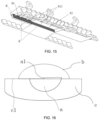
- the low-beam inflection-point primary optical unit 1 and the secondary optical unit 4 are fitted to form a low-beam central region light shape a, and a1 in the drawing is a low-beam inflection-point cut-off line of the low-beam central region light shape a, which has an inflection point;
- the low-beam widening primary optical unit 2 and the secondary optical unit 4 are fitted to form a low-beam widening region light shape c, and c1 in the drawing is a low-beam widening cut-off line of the low-beam widening region light shape c, which is preferably a horizontal line;
- the high-beam primary optical unit 3 and the secondary optical unit 4 are fitted to form a high-beam light shape b.
- the plurality of primary optical units are of different structures, and correspondingly, the secondary light entrance surfaces 42 corresponding to the primary optical units are also of different structures. Specific structures of the primary optical units will be described in detail below, and incidentally, the structure of the secondary light entrance surface 42 of the secondary optical unit 4 is described.
- the light guide portion of the low-beam inflection-point primary optical unit 1 is a low-beam light guide portion 11, the primary light emission surface thereof is a low-beam primary light emission surface 111, the secondary light entrance surface 42 corresponding to the low-beam primary light emission surface 111 includes four low-beam secondary light entrance surface 421, the low-beam secondary light entrance surface 421 is a curved surface protruding backwards, the low-beam secondary light entrance surfaces 421 are in one-to-one correspondence to the light entrance portions 5, and a low-beam inflection-point cut-off line structure 12 for forming a low-beam inflection-point cut-off line is provided on a front boundary of a lower surface of the low-beam light guide portion 11.
- the low-beam inflection-point cut-off line structure 12 on the low-beam light guide portion 11, there is no need to additionally use a light screen to block and form a cut-off line, and meanwhile, there is no need to arrange a driving mechanism to drive the light screen to achieve switch of high and low beams, thus eliminating mechanical failure, reducing components and parts, simplifying the structure, achieving a small occupied space, and a higher space utilization efficiency and light distribution efficiency.
- the shape of the low-beam secondary light entrance surface 421 may be obtained using a light refraction law and a curved surface fitting method according to parameters, such as the given secondary light emission surface 41, a focus, and the direction of emission light of the specific secondary light emission surface 41.
- the low-beam secondary light entrance surface 421 and a corresponding part of the secondary light emission surface 41 form a single focus together, so as to converge the light emitted from the low-beam primary light emission surface 111 in the up-down and left-right directions to form a low-beam inflection-point cut-off line with an inflection point.
- low-beam inflection-point cut-off line structures 12 in different forms may be provided; for example, the low-beam inflection-point cut-off line structure 12 includes at least one left-hand-driving cut-off line structure 121 and at least one right-hand-driving cut-off line structure 122, and the left-hand-driving cut-off line structures 121 and the right-hand-driving cut-off line structures 122 are in one-to-one correspondence to the light entrance portions 5, as shown specifically in FIGS. 9 and 10 .
- the low-beam inflection-point cut-off line structure 12 includes two left-hand-driving cut-off line structures 121 and two right-hand-driving cut-off line structures 122 connected in sequence.
- light is emitted from a part of the low-beam primary light emission surface 111 corresponding to the left-hand-driving cut-off line structure 121, it will be intercepted by the left-hand-driving cut-off line structure 121, such that all the light is emitted above the left-hand-driving cut-off line structure 121, and then emitted by the secondary optical unit 4 to form a left-hand-driving low-beam central region light shape with a left-hand-driving low-beam inflection-point cut-off line; when the light is emitted from a part of the low-beam primary light emission surface 111 corresponding to the right-hand-driving cut-off line structure 122, it will be intercepted by the right-hand-driving
- left-hand-driving cut-off line structure 121 and the right-hand-driving cut-off line structure 122 are provided in one vehicle lamp optical assembly, operations, such as dimming and light source switching, are performed according to actual requirements, such that a switch of left-hand driving and right-hand driving may be achieved, so as to meet the use of the vehicle lamp optical assembly for vehicle lamps in different regions around the world, and reduce redevelopment and design of the lamps.
- the number of the left-hand-driving cut-off line structure 121 and the number of the right-hand-driving cut-off line structure 122 may be set to one respectively, or may be set to a plurality according to the illuminance requirement of a low-beam central region, and they are preferably arranged at corresponding focuses thereof.
- a plurality of identical left-hand-driving cut-off line structures 121 or right-hand-driving cut-off line structures 122 may be sequentially arranged in the left-right direction, and each of light source switches corresponding to the left-hand-driving cut-off line structures 121 or right-hand-driving cut-off line structures 122 is independently controlled to realize horizontal movement of the low-beam inflection-point cut-off line, i.e., movement of a low-beam inflection point, for implementing an adaptive front lighting system (AFS).
- AFS adaptive front lighting system
- the 11 includes four left-hand-driving cut-off line structures 121 connected in sequence, four light entrance portions 5 corresponding to the left-hand-driving cut-off line structures 121 are provided on the light entrance portion mounting surface of the low-beam light guide portion 11, light sources are provided at light entrance ends of the respective light entrance portions 5, and adaptive front lighting is realized by independently controlling each of the light sources to be turned on or off.
- the 12 includes four right-hand-driving cut-off line structures 122 connected in sequence, and similarly, four light entrance portions 5 corresponding to the right-hand-driving cut-off line structures 122 are provided on the light entrance portion mounting surface of the low-beam light guide portion 11, light sources are provided at light entrance ends of the respective light entrance portions 5, and adaptive front lighting is realized by independently controlling the light sources to be turned on or off.
- a III-region structure 6 for forming a low-beam III-region light shape is provided at a lower portion of a front end of the low-beam light guide portion 11.
- the III-region structure 6, a lower surface of the low-beam light guide portion 11 and a rear end of the low-beam light guide portion 11 form an upwardly concave groove 7, and the low-beam inflection-point cut-off line structure 12 is formed at a junction between the III-region structure 6 and a top of the groove 7.
- a part of light emitted by the light entrance portion 5 enters the low-beam light guide portion 11 and is intercepted by the low-beam inflection-point cut-off line structure 12, then is projected by the secondary optical unit 4 again to form the low-beam central region light shape a with the low-beam inflection-point cut-off line; the other part of the light emitted by the light entrance portion 5 directly enters the III-region structure 6 through the groove 7 and is projected by the secondary optical unit 4 to form the low-beam III-region light shape.
- the light guide portion of the low-beam widening primary optical unit 2 is a low-beam widening light guide portion 21.
- the low-beam widening cut-off line of the low-beam widening region light shape c is a horizontal line without an inflection point, and a corresponding part of the secondary optical unit 4 may not have a single focus, but have a focal line composed of several focuses, that is, it is not required to provide the secondary light entrance surface 42 protruding rearwards, and therefore, in order to facilitate mounting of the vehicle lamp optical assembly and to make the structure more compact
- the low-beam widening light guide portion 21 and the secondary optical unit 4 are preferably connected into a whole, a low-beam widening cut-off line structure for forming the low-beam widening cut-off line is provided on a lower surface of the low-beam widening light guide portion 21, and the low-beam widening cut-off line structure is preferably
- a III-region structure 6 for forming a low-beam III-region light shape is provided at a lower portion of a front end of the low-beam widening light guide portion 21.
- the III-region structure 6, a lower surface of the low-beam widening light guide portion 21 and a rear end of the low-beam widening light guide portion 21 form an upwardly concave groove 7, and the low-beam widening cut-off line structure is formed at a junction between the III-region structure 6 and a top of the groove 7.
- a part of light emitted by the light entrance portion 5 enters the low-beam widening light guide portion 21 and is intercepted by the low-beam widening cut-off line structure, then is projected by the secondary optical unit 4 again to form the low-beam widening region light shape c with the low-beam widening cut-off line; the other part of the light emitted by the light entrance portion 5 directly enters the III-region structure 6 through the groove 7 and is projected by the secondary optical unit 4 to form the low-beam III-region light shape.
- the light guide portion of the high-beam primary optical unit 3 is a high-beam light guide portion 31, the primary light emission surface thereof is a high-beam primary light emission surface 311, the secondary light entrance surface 42 corresponding to the high-beam primary light emission surface 311 includes six high-beam secondary light entrance surfaces 422, the high-beam secondary light entrance surfaces 422 are curved surfaces protruding backwards, and the high-beam secondary light entrance surfaces 422 are in one-to-one correspondence to the light entrance portions 5.
- the light emitted from the light entrance portion 5 enters the high-beam light guide portion 31 and is projected by the secondary optical unit 4 to form the high-beam light shape.
- an irradiation region of the vehicle lamp may be controlled by controlling the respective light sources to be turned on or off, so as to avoid a region where a facing movement vehicle is located, and a dazzling problem is avoided, thereby achieving an intelligent anti-dazzling effect, that is, realizing an adaptive driving beam (ADB), wherein the number of the light sources is determined by pixels of the ADB required to be implemented.
- ADB adaptive driving beam
- the shape of the high-beam secondary light entrance surface 422 may be obtained using a light refraction law and a curved surface fitting method according to parameters, such as the given secondary light emission surface 41, a focus, and the direction of emission light of the specific secondary light emission surface 41.
- the high-beam light guide portion 31 is different from the low-beam light guide portion 11 in that emission light of the primary light emission surfaces thereof has different directions to form corresponding light shapes, and since the low-beam light shape should be located below the high-beam light shape on a light distribution screen, in the present embodiment, the low-beam inflection-point cut-off line structure 12 is provided on the front boundary of the lower surface of the low-beam light guide portion 11, such that all the emission light of the light entrance portion 5 may be emitted above the low-beam inflection-point cut-off line structure 12, and projected by the secondary optical unit 4 to form the low-beam central region light shape a located below the high-beam light shape b.
- the above-mentioned low-beam inflection-point primary optical unit 1, the low-beam widening primary optical unit 2, and the high-beam primary optical unit 3 may be arranged separately or integrally by connecting.
- the separate arrangement facilitates dimming among the primary optical units
- the integral arrangement facilitates an improvement of positioning and mounting precision among the primary optical units.
- the light guide portions of the plurality of primary optical units in the primary optical unit group are connected into a whole, an auxiliary light source is provided on at least one side of the primary optical unit or the primary optical unit group in the left-right direction of the light guide portion, and when the auxiliary light source is turned on, light emitted by the auxiliary light source enters from a side surface of the light guide portion and is emitted from the primary light emission surface, finally is emitted through the secondary light emission surface 41.
- the auxiliary light source may be provided to achieve a daytime running light function or a low-beam III-region function by adjusting the luminous flux of the auxiliary light source.
- the auxiliary light source is turned on, and the secondary light emission surface 41 emits light when viewed from the outside; that is, the secondary light emission surface 41 is overall lightened, so as to realize a whole lamp lightening effect to achieve the daytime running light function.
- the auxiliary light source and the light source corresponding to the light entrance portion 5 are turned on simultaneously, and the emission light of the auxiliary light source may, independently or jointly with light incident from a III-region light entrance surface 61, realize the illuminance and angle of the low-beam III-region light shape which meet regulatory requirements.
- the vehicle lamp optical assembly includes: a primary optical unit group composed of a low-beam inflection-point primary optical unit 1, a low-beam widening primary optical unit 2, and a high-beam primary optical unit 3I and one secondary optical unit 4, wherein the low-beam widening primary optical unit 2 is provided between the low-beam inflection-point primary optical unit 1 and the high-beam primary optical unit 3, the light guide portions of the low-beam inflection-point primary optical unit 1, the low-beam widening primary optical unit 2 and the high-beam primary optical unit 3 are connected into a whole, auxiliary light sources are provided on two sides of the integrally connected light guide portions in the left-right direction respectively, a light converging structure 8 is provided between the auxiliary light source and the light guide portion.
- a primary optical unit group composed of a low-beam inflection-point primary optical unit 1, a low-beam widening primary optical unit 2, and a high-beam primary optical unit 3I and one secondary optical unit 4, where
- the light converging structure 8 By providing the light converging structure 8, more light can enter from the side surface of the light guide portion thereby improving a light utilization rate of the light sources on the two sides.
- the light converging structure 8 may be a light converging cup structure or a convex structure protruding towards the direction of the auxiliary light source.
- the auxiliary light source is provided on one side of the III-region structure 6 of the low-beam light guide portion 11
- concave-convex structures 611 are provided on the III-region light entrance surfaces 61 of the low-beam light guide portion 11 and the low-beam widening light guide portion 21, and the concave-convex structure 611 may be a striped concave-convex structure as shown in FIGS. 12 and 13 , a grid-shaped concave-convex structure, or a zigzag concave-convex structure.
- the concave-convex structure 611 may diffuse the light emitted from the III-region light entrance surface 61, so as to improve uniformity of the low-beam III-region light shape; on the other hand, when the auxiliary light sources on two sides are turned on, the light emitted by the auxiliary light sources enters from the side surfaces of the light guide portions and is reflected by the III-region light entrance surface 61, then is emitted from the primary light emission surface.
- the arrangement of the concave-convex structure 611 may enable more light emitted by the auxiliary light sources to be fully reflected, emitted from the primary light emission surface, and uniformly emitted to the secondary light emission surface 41, so as to achieve effects of uniform illumination and an improved light utilization ratio.
- the light entrance portion 5 is preferably of a light converging cup structure, and may better converge light in the up-down and left-right directions.
- An outer contour surface of the light entrance portion 5 is a curved surface with a diameter gradually increased from rear to front, and is a solid body having a light entrance surface and a light emission surface located at the front and rear ends thereof.
- the light entrance surface and the light emission surface may be flat surfaces or curved surfaces; or, the outer contour surface of the light entrance portion 5 is a curved surface with the diameter gradually increased from rear to front, the interior of which is provided with a cavity structure recessed forwards, and a protrusion protruding backwards is provided within the cavity; or, the light entrance portion 5 is of a convex structure protruding backwards.
- each of an upper surface and a lower surface of the light guide portion is provided with a concave or convex pattern structure, such that more light emitted from the light guide portion may be reflected to the primary light emission surface by the upper surface and the lower surface of the light guide portion, thus improving a light utilization efficiency; or the whole or part of the upper surface and the lower surface of the light guide portion is provided with a plated film, so as to improve reflectivity of the light inside the light guide portion.
- the plated film may be aluminum plated or silver plated.
- a refraction condition of the light refracted by the groove 7 may be improved by adjusting the vertical height of the above-mentioned groove 7 and the inclination directions and gradients of front and back sidewalls.
- a second aspect of the present invention further provides a vehicle lamp module, including the vehicle lamp optical assembly according to the first aspect and at least one light source, wherein the light sources are in one-to-one correspondence to the light entrance portions 5.
- optical axis of the light source coincides with optical axis of the light entrance portion 5 or there is a horizontal included angle between, wherein the horizontal included angle is preferably 0° to 15°.
- the horizontal deflection angle of 0° to 15° between the optical axis of the light source and the optical axis of the light entrance portion 5 the emission light of the light source is emitted to the left side and the right side of the vehicle lamp module, thus achieving the effect of light shape extension in the horizontal direction.
- each of the light sources can be independently controlled to be turned on or off, such that during high beam illumination, an irradiation region of the vehicle lamp is controlled by controlling the light sources to be turned on or off, so as to avoid a region where a facing movement vehicle is located, and a dazzling problem is avoided, thereby achieving an intelligent anti-dazzling effect.
- the arrangement of the vehicle lamp optical assembly can realize the design of size miniaturization and shape diversification.
- a third aspect of the present invention further provides a vehicle lamp, including the vehicle lamp module according to the second aspect.
- the vehicle lamp can realize the design of size miniaturization and shape diversification.
- a fourth aspect of the present invention further provides a vehicle, including the vehicle lamp according to the third aspect.
- the vehicle By arranging the vehicle lamp, the vehicle can realize the design of shape diversification, which is favorable to an improvement of the overall visual effect and attractiveness of a vehicle body.
- the design of miniaturization and diversification in size and shape can be realized by arranging the narrow and long secondary light emission surface 41;
- the present invention may realize low beam illumination and high beam illumination, has the functions of ADB (adaptive driving beam), AFS (adaptive front lighting system) and daytime running light, and has the characteristics of a simple structure and diversified functions;
- the low-beam inflection-point cut-off line structure 12 may meet the left-hand-driving and right-hand-driving requirements independently or simultaneously, such that it is realized that vehicles in different regions around the world share the same lamp system, thus avoiding repeated development and design of lamps.
- the vehicle lamp optical assembly according to the present invention may be directly applied to the vehicle body without an external lens, thus improving an optical efficiency, improving the visual effect in shape, and meeting the requirements of miniaturization, a high efficiency and a novel shape of a current vehicle lamp.
Landscapes
- Engineering & Computer Science (AREA)
- General Engineering & Computer Science (AREA)
- Physics & Mathematics (AREA)
- Microelectronics & Electronic Packaging (AREA)
- Optics & Photonics (AREA)
- Non-Portable Lighting Devices Or Systems Thereof (AREA)
- Lighting Device Outwards From Vehicle And Optical Signal (AREA)
Description
- The present application claims benefits of
Chinese Patent Application No. 202010633980.4, filed on July 02, 2020 - The present invention relates to a vehicle lamp, and particularly to a vehicle lamp optical assembly. In addition, the present invention further relates to a vehicle lamp module, a vehicle lamp and a vehicle.
- Currently, in an illumination optical system of a vehicle lamp of a vehicle, there are mainly two types of implementation for high and low beams called lens-type and reflection-type. A reflection-type illumination system includes a light source and a reflector, wherein light emitted by the light source directly passes through an external lens to form illumination light of a vehicle after reflected by the reflector; a lens-type illumination system includes a light source, a reflector and a lens, wherein light emitted by the light source is reflected by the reflector, then is imaged by the lens and finally forms the high and low beams required by vehicle illumination by an external lens.
- The above lens-type or reflection-type illumination system has a single form and is limited by the size of the lens or the reflector, and it is quite difficult for a vehicle-lamp high and low beam module thereof to have a quite small opening (the opening of the vehicle-lamp high and low beam module refers to the height of a light emission side of the module), such that more miniaturized and diversified design of the vehicle lamp in size and shape cannot be realized.
- Known vehicle lamps are disclosed in
WO 2019/229191 A andEP 3299703 A . - The technical problem to be solved by the present invention is to provide a vehicle lamp optical assembly, which can realize the design of miniaturization and shape diversification.
- In order to solve the above technical problem, the present invention provides a vehicle lamp optical assembly as defined in
independent claim 1. - Preferred embodiments are defined in the dependent claims.
- In the present invention, by configuring the secondary light emission surface as a narrow and long smooth curved surface without a section difference and arranging the light entrance portion and the light guide portion, the vehicle lamp optical assembly can have a quite small overall vertical height, thereby realizing a miniaturization design in size of a small opening; the secondary light emission surface has various shapes and high adaptability, so that shape requirements of different vehicle lamps may be met, and a diversification design in shaping is realized.
- Other features and advantages of the present invention will be described in detail in the following detailed description.
-
-
FIG. 1 is a schematic front perspective structural diagram according to an embodiment; -
FIG. 2 is a first schematic back perspective structural diagram according to an embodiment; -
FIG. 3 is a second schematic back perspective structural diagram according to an embodiment; -
FIG. 4 is a third schematic back perspective structural diagram according to an embodiment; -
FIG. 5 is a bottom view ofFIG. 1 ; -
FIG. 6 is a sectional view taken along A-A ofFIG. 5 . -
FIG. 7 is a sectional view taken along B-B ofFIG. 5 . -
FIG. 8 is a sectional view taken along C-C ofFIG. 5 . -
FIG. 9 is a fourth schematic back perspective structural diagram according to an embodiment; -
FIG. 10 is a schematic structural diagram of a corresponding low-beam inflection-point cut-off line structure at D inFIG. 9 ; -
FIG. 11 is a schematic diagram of a low-beam inflection-point cut-off line structure of a low-beam inflection-point primary optical unit in an embodiment; -
FIG. 12 is a schematic diagram of another low-beam inflection-point cut-off line structure of a low-beam inflection-point primary optical unit in an embodiment; -
FIG. 13 is a schematic enlarged structural diagram at E inFIG. 12 ; -
FIG. 14 is a first schematic structural diagram according to an embodiment of the present invention; -
FIG. 15 is a second schematic structural diagram according to another embodiment of the present invention; and -
FIG. 16 is a schematic diagram of a light shape according to an embodiment. -
1 low-beam inflection-point primary optical unit 11 low-beam light guide portion 111 low-beam primary light emission surface 12 low-beam inflection-point cut-off line structure 121 left-hand-driving cut-off line structure 122 right-hand-driving cut-off line structure 2 low-beam widening primary optical unit 21 low-beam widening light guide portion 3 high-beam primary optical unit 31 high-beam light guide portion 311 high-beam primary light emission surface 4 secondary optical unit 41 secondary light emission surface 42 secondary light entrance surface 421 low-beam secondary light entrance surface 422 high-beam secondary light entrance surface 5 light entrance portion 6 III- region structure 61 III-region light entrance surface 611 concave- convex structure 7 groove 8 light converging structure a low-beam central region light shape a1 low-beam inflection-point cut-off line b high-beam light shape c low-beam widening region light shape c1 low-beam widening cut-off line - In descriptions of the present invention, it should be understood that, orientations or positional relationships indicated by terms "upper", "lower", "front", "rear", "left", "right" etc. are based on orientations or positional relationships shown in
FIG. 2 , and they are only used to facilitate the description of the present invention and simplify the description, but do not indicate or imply that an indicated device or element must have a specific orientation or be constructed and operated in a specific orientation. Therefore, it cannot be understood as a limitation on the present invention. - Embodiments of the present invention will be described in detail below with reference to the accompanying drawings. It should be understood that the specific embodiments described herein are merely for illustrating and explaining the present invention and are not intended to limit the present invention.
- As shown in
FIGS. 1 to 16 , the present invention provides a vehicle lamp optical assembly, comprising: a primary optical unit or a primary optical unit group having a plurality of primary optical units arranged side by side, wherein the primary optical unit includes alight entrance portion 5 and a light guide portion, the light guide portion has a light entrance portion mounting surface and a primary light emission surface, the light entrance portion mounting surface is provided with at least onelight entrance portion 5, thelight entrance portion 5 is configured to enable incident light to be converged and emitted to the light guide portion, and the light guide portion is configured to guide the incident light to be emitted from the primary light emission surface; and a secondaryoptical unit 4, wherein the secondaryoptical unit 4 has a secondarylight emission surface 41 and a secondarylight entrance surface 42 corresponding to the primary light emission surface, and the secondarylight emission surface 41 is a narrow and long smooth curved surface. - Since the secondary
optical unit 4 may be fitted with one or more primary optical units, the secondarylight emission surface 41 of the secondaryoptical unit 4 is a light emission surface of the whole vehicle lamp optical assembly; by configuring the secondarylight emission surface 41 to be a narrow and long smooth curved surface without a section difference, and arranging thelight entrance portion 5 and the light guide portion, a better converging effect can be achieved for light in the up-down direction, such that the up-down height of the secondarylight emission surface 41 may be in the millimeter order, and the up-down heights of thelight entrance portion 5 and the light guide portion may also be quite small, therefore, the overall up-down height of the vehicle lamp optical assembly can be quite small, so as to realize a miniaturization design of a small opening. - Wherein, the secondary
light emission surface 41 may be a columnar curved surface. that is, a longitudinal sectional line of the secondarylight emission surface 41 is an arc line protruding forwards, and a transverse sectional line of the secondarylight emission surface 41 is a straight line extending in the left-right direction; or a transverse sectional line of the secondarylight emission surface 41 is a curve extending in the left-right direction, and the secondarylight emission surface 41 is formed by sweeping the longitudinal sectional line along the transverse sectional line thereof. The secondarylight emission surface 41 has various shapes, high adaptability, so that shape requirements of different vehicle lamps may be met, and diversification design in shaping is realized. - Specifically, the primary optical unit is a low-beam inflection-point primary
optical unit 1, a low-beam widening primaryoptical unit 2 or a high-beam primaryoptical unit 3, and the primary optical unit group includes at least one or more of the low-beam inflection-point primaryoptical unit 1, the low-beam widening primaryoptical unit 2 and the high-beam primaryoptical unit 3. The low-beam inflection-point primaryoptical unit 1 and the secondaryoptical unit 4 can be fitted to form a low-beam central region light shape a with a low-beam inflection-point cut-off line; the low-beam widening primaryoptical unit 2 and the secondaryoptical unit 4 can be fitted to form a low-beam widening region light shape c with a low-beam widening cut-off line; and the high-beam primaryoptical unit 3 and the secondaryoptical unit 4 can be fitted to form a high-beam light shape b, thereby achieving plural illumination functions independently or simultaneously to meet diversified design requirements of a vehicle lamp. - As a specific embodiment, as shown in
FIGS. 1 to 10 , the vehicle lamp optical assembly includes: a primary optical unit group composed of a low-beam inflection-point primaryoptical unit 1, a low-beam widening primaryoptical unit 2 and a high-beam primaryoptical unit 3; and one secondaryoptical unit 4. The low-beam widening primaryoptical unit 2 is provided between the low-beam inflection-point primaryoptical unit 1 and the high-beam primaryoptical unit 3. The vehicle lamp optical assembly can form three light shapes as shown inFIG. 16 , wherein the low-beam inflection-point primaryoptical unit 1 and the secondaryoptical unit 4 are fitted to form a low-beam central region light shape a, and a1 in the drawing is a low-beam inflection-point cut-off line of the low-beam central region light shape a, which has an inflection point; the low-beam widening primaryoptical unit 2 and the secondaryoptical unit 4 are fitted to form a low-beam widening region light shape c, and c1 in the drawing is a low-beam widening cut-off line of the low-beam widening region light shape c, which is preferably a horizontal line; and the high-beam primaryoptical unit 3 and the secondaryoptical unit 4 are fitted to form a high-beam light shape b. - Since the functions to be achieved are different, the plurality of primary optical units are of different structures, and correspondingly, the secondary
light entrance surfaces 42 corresponding to the primary optical units are also of different structures. Specific structures of the primary optical units will be described in detail below, and incidentally, the structure of the secondarylight entrance surface 42 of the secondaryoptical unit 4 is described. - Specifically, the light guide portion of the low-beam inflection-point primary
optical unit 1 is a low-beamlight guide portion 11, the primary light emission surface thereof is a low-beam primarylight emission surface 111, the secondarylight entrance surface 42 corresponding to the low-beam primarylight emission surface 111 includes four low-beam secondarylight entrance surface 421, the low-beam secondarylight entrance surface 421 is a curved surface protruding backwards, the low-beam secondarylight entrance surfaces 421 are in one-to-one correspondence to thelight entrance portions 5, and a low-beam inflection-point cut-offline structure 12 for forming a low-beam inflection-point cut-off line is provided on a front boundary of a lower surface of the low-beamlight guide portion 11. By providing the low-beam inflection-point cut-offline structure 12 on the low-beamlight guide portion 11, there is no need to additionally use a light screen to block and form a cut-off line, and meanwhile, there is no need to arrange a driving mechanism to drive the light screen to achieve switch of high and low beams, thus eliminating mechanical failure, reducing components and parts, simplifying the structure, achieving a small occupied space, and a higher space utilization efficiency and light distribution efficiency. - The shape of the low-beam secondary
light entrance surface 421 may be obtained using a light refraction law and a curved surface fitting method according to parameters, such as the given secondarylight emission surface 41, a focus, and the direction of emission light of the specific secondarylight emission surface 41. The low-beam secondarylight entrance surface 421 and a corresponding part of the secondarylight emission surface 41 form a single focus together, so as to converge the light emitted from the low-beam primarylight emission surface 111 in the up-down and left-right directions to form a low-beam inflection-point cut-off line with an inflection point. - In order to meet different driving requirements, i.e., to achieve left-hand driving or right-hand driving requirements, low-beam inflection-point cut-off
line structures 12 in different forms may be provided; for example, the low-beam inflection-point cut-offline structure 12 includes at least one left-hand-driving cut-offline structure 121 and at least one right-hand-driving cut-offline structure 122, and the left-hand-driving cut-offline structures 121 and the right-hand-driving cut-offline structures 122 are in one-to-one correspondence to thelight entrance portions 5, as shown specifically inFIGS. 9 and 10 . The low-beam inflection-point cut-offline structure 12 includes two left-hand-driving cut-offline structures 121 and two right-hand-driving cut-offline structures 122 connected in sequence. When light is emitted from a part of the low-beam primarylight emission surface 111 corresponding to the left-hand-driving cut-offline structure 121, it will be intercepted by the left-hand-driving cut-offline structure 121, such that all the light is emitted above the left-hand-driving cut-offline structure 121, and then emitted by the secondaryoptical unit 4 to form a left-hand-driving low-beam central region light shape with a left-hand-driving low-beam inflection-point cut-off line; when the light is emitted from a part of the low-beam primarylight emission surface 111 corresponding to the right-hand-driving cut-offline structure 122, it will be intercepted by the right-hand-driving cut-offline structure 122, such that all the light is emitted above the right-hand-driving cut-offline structure 122, and then emitted from the secondaryoptical unit 4 to form a right-hand-driving low-beam central region light shape with a right-hand-driving low-beam inflection-point cut-off line. Thus, by providing the left-hand-driving cut-offline structure 121 and the right-hand-driving cut-offline structure 122 in one vehicle lamp optical assembly, operations, such as dimming and light source switching, are performed according to actual requirements, such that a switch of left-hand driving and right-hand driving may be achieved, so as to meet the use of the vehicle lamp optical assembly for vehicle lamps in different regions around the world, and reduce redevelopment and design of the lamps. The number of the left-hand-driving cut-offline structure 121 and the number of the right-hand-driving cut-offline structure 122 may be set to one respectively, or may be set to a plurality according to the illuminance requirement of a low-beam central region, and they are preferably arranged at corresponding focuses thereof. - In addition, a plurality of identical left-hand-driving cut-off
line structures 121 or right-hand-driving cut-offline structures 122 may be sequentially arranged in the left-right direction, and each of light source switches corresponding to the left-hand-driving cut-offline structures 121 or right-hand-driving cut-offline structures 122 is independently controlled to realize horizontal movement of the low-beam inflection-point cut-off line, i.e., movement of a low-beam inflection point, for implementing an adaptive front lighting system (AFS). Specifically, as shown inFIGS. 11 and 12 , the low-beam inflection-point cut-offline structure 12 inFIG. 11 includes four left-hand-driving cut-offline structures 121 connected in sequence, fourlight entrance portions 5 corresponding to the left-hand-driving cut-offline structures 121 are provided on the light entrance portion mounting surface of the low-beamlight guide portion 11, light sources are provided at light entrance ends of the respectivelight entrance portions 5, and adaptive front lighting is realized by independently controlling each of the light sources to be turned on or off. The low-beam inflection-point cut-offline structure 12 inFIG. 12 includes four right-hand-driving cut-offline structures 122 connected in sequence, and similarly, fourlight entrance portions 5 corresponding to the right-hand-driving cut-offline structures 122 are provided on the light entrance portion mounting surface of the low-beamlight guide portion 11, light sources are provided at light entrance ends of the respectivelight entrance portions 5, and adaptive front lighting is realized by independently controlling the light sources to be turned on or off. - More specifically, as shown in
FIGS. 5 and6 , a III-region structure 6 for forming a low-beam III-region light shape is provided at a lower portion of a front end of the low-beamlight guide portion 11. The III-region structure 6, a lower surface of the low-beamlight guide portion 11 and a rear end of the low-beamlight guide portion 11 form an upwardlyconcave groove 7, and the low-beam inflection-point cut-offline structure 12 is formed at a junction between the III-region structure 6 and a top of thegroove 7. Thus, a part of light emitted by thelight entrance portion 5 enters the low-beamlight guide portion 11 and is intercepted by the low-beam inflection-point cut-offline structure 12, then is projected by the secondaryoptical unit 4 again to form the low-beam central region light shape a with the low-beam inflection-point cut-off line; the other part of the light emitted by thelight entrance portion 5 directly enters the III-region structure 6 through thegroove 7 and is projected by the secondaryoptical unit 4 to form the low-beam III-region light shape. - Specifically, as shown in
FIGS. 5 and7 , the light guide portion of the low-beam widening primaryoptical unit 2 is a low-beam wideninglight guide portion 21. Since the low-beam widening cut-off line of the low-beam widening region light shape c is a horizontal line without an inflection point, and a corresponding part of the secondaryoptical unit 4 may not have a single focus, but have a focal line composed of several focuses, that is, it is not required to provide the secondarylight entrance surface 42 protruding rearwards, and therefore, in order to facilitate mounting of the vehicle lamp optical assembly and to make the structure more compact, the low-beam wideninglight guide portion 21 and the secondaryoptical unit 4 are preferably connected into a whole, a low-beam widening cut-off line structure for forming the low-beam widening cut-off line is provided on a lower surface of the low-beam wideninglight guide portion 21, and the low-beam widening cut-off line structure is preferably provided on the above-mentioned focal line. - Similarly, a III-
region structure 6 for forming a low-beam III-region light shape is provided at a lower portion of a front end of the low-beam wideninglight guide portion 21. The III-region structure 6, a lower surface of the low-beam wideninglight guide portion 21 and a rear end of the low-beam wideninglight guide portion 21 form an upwardlyconcave groove 7, and the low-beam widening cut-off line structure is formed at a junction between the III-region structure 6 and a top of thegroove 7. Thus, a part of light emitted by thelight entrance portion 5 enters the low-beam wideninglight guide portion 21 and is intercepted by the low-beam widening cut-off line structure, then is projected by the secondaryoptical unit 4 again to form the low-beam widening region light shape c with the low-beam widening cut-off line; the other part of the light emitted by thelight entrance portion 5 directly enters the III-region structure 6 through thegroove 7 and is projected by the secondaryoptical unit 4 to form the low-beam III-region light shape. - Specifically, the light guide portion of the high-beam primary
optical unit 3 is a high-beamlight guide portion 31, the primary light emission surface thereof is a high-beam primarylight emission surface 311, the secondarylight entrance surface 42 corresponding to the high-beam primarylight emission surface 311 includes six high-beam secondary light entrance surfaces 422, the high-beam secondary light entrance surfaces 422 are curved surfaces protruding backwards, and the high-beam secondary light entrance surfaces 422 are in one-to-one correspondence to thelight entrance portions 5. Thus, the light emitted from thelight entrance portion 5 enters the high-beamlight guide portion 31 and is projected by the secondaryoptical unit 4 to form the high-beam light shape. In high beam illumination, road surface condition, and whether pedestrians or vehicles exist in a lane ahead or on the other side may be sensed by automobile sensors. Since the high-beam primaryoptical unit 3 is provided with the plurality oflight entrance portions 5, and correspondingly, the light entrance ends of thelight entrance portions 5 are correspondingly provided with the light sources, and light emitted by the light sources has different irradiation regions, an irradiation region of the vehicle lamp may be controlled by controlling the respective light sources to be turned on or off, so as to avoid a region where a facing movement vehicle is located, and a dazzling problem is avoided, thereby achieving an intelligent anti-dazzling effect, that is, realizing an adaptive driving beam (ADB), wherein the number of the light sources is determined by pixels of the ADB required to be implemented. - The shape of the high-beam secondary
light entrance surface 422 may be obtained using a light refraction law and a curved surface fitting method according to parameters, such as the given secondarylight emission surface 41, a focus, and the direction of emission light of the specific secondarylight emission surface 41. In addition, it should be noted that the high-beamlight guide portion 31 is different from the low-beamlight guide portion 11 in that emission light of the primary light emission surfaces thereof has different directions to form corresponding light shapes, and since the low-beam light shape should be located below the high-beam light shape on a light distribution screen, in the present embodiment, the low-beam inflection-point cut-offline structure 12 is provided on the front boundary of the lower surface of the low-beamlight guide portion 11, such that all the emission light of thelight entrance portion 5 may be emitted above the low-beam inflection-point cut-offline structure 12, and projected by the secondaryoptical unit 4 to form the low-beam central region light shape a located below the high-beam light shape b. - The above-mentioned low-beam inflection-point primary
optical unit 1, the low-beam widening primaryoptical unit 2, and the high-beam primaryoptical unit 3 may be arranged separately or integrally by connecting. The separate arrangement facilitates dimming among the primary optical units, and the integral arrangement facilitates an improvement of positioning and mounting precision among the primary optical units. - The light guide portions of the plurality of primary optical units in the primary optical unit group are connected into a whole, an auxiliary light source is provided on at least one side of the primary optical unit or the primary optical unit group in the left-right direction of the light guide portion, and when the auxiliary light source is turned on, light emitted by the auxiliary light source enters from a side surface of the light guide portion and is emitted from the primary light emission surface, finally is emitted through the secondary
light emission surface 41. The auxiliary light source may be provided to achieve a daytime running light function or a low-beam III-region function by adjusting the luminous flux of the auxiliary light source. During the application to the daytime running light function, only the auxiliary light source is turned on, and the secondarylight emission surface 41 emits light when viewed from the outside; that is, the secondarylight emission surface 41 is overall lightened, so as to realize a whole lamp lightening effect to achieve the daytime running light function. During the application to the low-beam III-region function, the auxiliary light source and the light source corresponding to thelight entrance portion 5 are turned on simultaneously, and the emission light of the auxiliary light source may, independently or jointly with light incident from a III-regionlight entrance surface 61, realize the illuminance and angle of the low-beam III-region light shape which meet regulatory requirements. - Specifically, as shown in
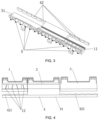
FIGS. 14 and15 , the vehicle lamp optical assembly includes: a primary optical unit group composed of a low-beam inflection-point primaryoptical unit 1, a low-beam widening primaryoptical unit 2, and a high-beam primary optical unit 3I and one secondaryoptical unit 4, wherein the low-beam widening primaryoptical unit 2 is provided between the low-beam inflection-point primaryoptical unit 1 and the high-beam primaryoptical unit 3, the light guide portions of the low-beam inflection-point primaryoptical unit 1, the low-beam widening primaryoptical unit 2 and the high-beam primaryoptical unit 3 are connected into a whole, auxiliary light sources are provided on two sides of the integrally connected light guide portions in the left-right direction respectively, alight converging structure 8 is provided between the auxiliary light source and the light guide portion. By providing thelight converging structure 8, more light can enter from the side surface of the light guide portion thereby improving a light utilization rate of the light sources on the two sides. Thelight converging structure 8 may be a light converging cup structure or a convex structure protruding towards the direction of the auxiliary light source. - Preferably, the auxiliary light source is provided on one side of the III-
region structure 6 of the low-beamlight guide portion 11, concave-convex structures 611 are provided on the III-region light entrance surfaces 61 of the low-beamlight guide portion 11 and the low-beam wideninglight guide portion 21, and the concave-convex structure 611 may be a striped concave-convex structure as shown inFIGS. 12 and13 , a grid-shaped concave-convex structure, or a zigzag concave-convex structure. On the one hand, the concave-convex structure 611 may diffuse the light emitted from the III-regionlight entrance surface 61, so as to improve uniformity of the low-beam III-region light shape; on the other hand, when the auxiliary light sources on two sides are turned on, the light emitted by the auxiliary light sources enters from the side surfaces of the light guide portions and is reflected by the III-regionlight entrance surface 61, then is emitted from the primary light emission surface. The arrangement of the concave-convex structure 611 may enable more light emitted by the auxiliary light sources to be fully reflected, emitted from the primary light emission surface, and uniformly emitted to the secondarylight emission surface 41, so as to achieve effects of uniform illumination and an improved light utilization ratio. - On the basis of the above embodiments, the
light entrance portion 5 is preferably of a light converging cup structure, and may better converge light in the up-down and left-right directions. An outer contour surface of thelight entrance portion 5 is a curved surface with a diameter gradually increased from rear to front, and is a solid body having a light entrance surface and a light emission surface located at the front and rear ends thereof. The light entrance surface and the light emission surface may be flat surfaces or curved surfaces; or, the outer contour surface of thelight entrance portion 5 is a curved surface with the diameter gradually increased from rear to front, the interior of which is provided with a cavity structure recessed forwards, and a protrusion protruding backwards is provided within the cavity; or, thelight entrance portion 5 is of a convex structure protruding backwards. - Preferably, each of an upper surface and a lower surface of the light guide portion is provided with a concave or convex pattern structure, such that more light emitted from the light guide portion may be reflected to the primary light emission surface by the upper surface and the lower surface of the light guide portion, thus improving a light utilization efficiency; or the whole or part of the upper surface and the lower surface of the light guide portion is provided with a plated film, so as to improve reflectivity of the light inside the light guide portion. The plated film may be aluminum plated or silver plated. Furthermore, a refraction condition of the light refracted by the
groove 7 may be improved by adjusting the vertical height of the above-mentionedgroove 7 and the inclination directions and gradients of front and back sidewalls. - A second aspect of the present invention further provides a vehicle lamp module, including the vehicle lamp optical assembly according to the first aspect and at least one light source, wherein the light sources are in one-to-one correspondence to the
light entrance portions 5. - Preferably, optical axis of the light source coincides with optical axis of the
light entrance portion 5 or there is a horizontal included angle between, wherein the horizontal included angle is preferably 0° to 15°. By forming the horizontal deflection angle of 0° to 15° between the optical axis of the light source and the optical axis of thelight entrance portion 5, the emission light of the light source is emitted to the left side and the right side of the vehicle lamp module, thus achieving the effect of light shape extension in the horizontal direction. - Preferably, each of the light sources can be independently controlled to be turned on or off, such that during high beam illumination, an irradiation region of the vehicle lamp is controlled by controlling the light sources to be turned on or off, so as to avoid a region where a facing movement vehicle is located, and a dazzling problem is avoided, thereby achieving an intelligent anti-dazzling effect.
- The arrangement of the vehicle lamp optical assembly can realize the design of size miniaturization and shape diversification.
- A third aspect of the present invention further provides a vehicle lamp, including the vehicle lamp module according to the second aspect.
- By arranging the vehicle lamp module, the vehicle lamp can realize the design of size miniaturization and shape diversification.
- A fourth aspect of the present invention further provides a vehicle, including the vehicle lamp according to the third aspect.
- By arranging the vehicle lamp, the vehicle can realize the design of shape diversification, which is favorable to an improvement of the overall visual effect and attractiveness of a vehicle body.
- In summary, in the present invention, the design of miniaturization and diversification in size and shape can be realized by arranging the narrow and long secondary
light emission surface 41; the present invention may realize low beam illumination and high beam illumination, has the functions of ADB (adaptive driving beam), AFS (adaptive front lighting system) and daytime running light, and has the characteristics of a simple structure and diversified functions; the low-beam inflection-point cut-offline structure 12 may meet the left-hand-driving and right-hand-driving requirements independently or simultaneously, such that it is realized that vehicles in different regions around the world share the same lamp system, thus avoiding repeated development and design of lamps. The vehicle lamp optical assembly according to the present invention may be directly applied to the vehicle body without an external lens, thus improving an optical efficiency, improving the visual effect in shape, and meeting the requirements of miniaturization, a high efficiency and a novel shape of a current vehicle lamp. - The preferred embodiments of the present invention have been described in detail with reference to the accompanying drawings; however, the present invention is not limited to the specific details of the above embodiments, and various simple modifications may be made to the technical solutions of the present invention within the technical idea of the present invention, and these simple modifications all fall within the protection scope of the present invention as defined by the appended claims.
Claims (14)
- A vehicle lamp optical assembly, comprisinga primary optical unit group having a plurality of primary optical units (1, 2, 3) arranged side by side, wherein the primary optical unit (1, 2, 3) comprises a light entrance portion and a light guide portion (11, 21, 31), the light guide portion has a light entrance portion mounting surface and a primary light emission surface (111, 311), the light entrance portion mounting surface is provided with at least one light entrance portion (5), the light entrance portion (5) is configured to enable incident light to be converged and emitted in a forwards direction to the light guide portion, and the light guide portion is configured to be capable of guiding the incident light to be emitted in the forwards direction from the primary light emission surface; anda secondary optical unit (4), wherein the secondary optical unit (4) has a secondary light emission surface (41) and a secondary light entrance surface (42) corresponding to the primary light emission surface (111, 311), and the secondary light emission surface (41) is a narrow and long smooth curved surface;characterised in thatthe light guide portions of the plurality of primary optical units in the primary optical unit group are connected into a whole, an auxiliary light source is provided on at least one side of the primary optical unit group in a left-right direction of the light guide portion, wherein the left-right direction is transverse to the forwards direction, and light emitted by the auxiliary light source enters from a side surface of the light guide portion and is emitted from the primary light emission surface; a light converging structure (8) being provided between the auxiliary light source and the light guide portion.
- The vehicle lamp optical assembly according to claim 1, wherein a longitudinal sectional line of the secondary light emission surface (41) is an arc line protruding forwards, and a transverse sectional line of the secondary light emission surface (41) is a straight line or a curve extending in left-right direction.
- The vehicle lamp optical assembly according to claim 1, wherein the light entrance portion (5) is of a light converging cup structure, and an outer contour surface of the light entrance portion (5) is a curved surface with a diameter gradually increased from rear to front in the forwards direction.
- The vehicle lamp optical assembly according to claim 1, wherein each of an upper surface and a lower surface of the light guide portion is provided with a pattern structure or a plated film.
- The vehicle lamp optical assembly according to any one of claims 1 to 4, wherein the primary optical unit is a low-beam inflection-point primary optical unit (1), a low-beam widening primary optical unit (2) or a high-beam primary optical unit (3), and the primary optical unit group comprises at least one or more of the low-beam inflection-point primary optical units (1), the low-beam widening primary optical units (2) and the high-beam primary optical units (3).
- The vehicle lamp optical assembly according to claim 5, wherein the primary optical unit group comprises a low-beam inflection-point primary optical unit (1), a low-beam widening primary optical unit (2), and a high-beam primary optical unit (3), and the low-beam widening primary optical unit (2) is provided between the low-beam inflection-point primary optical unit (1) and the high-beam primary optical unit (3).
- The vehicle lamp optical assembly according to claim 5, wherein the light guide portion of the low-beam inflection-point primary optical unit (1) is a low-beam light guide portion (11), the primary light emission surface of the low-beam light guide portion (11) is a low-beam primary light emission surface (111), the secondary light entrance surface (42) corresponding to the low-beam primary light emission surface (111) comprises at least one low-beam secondary light entrance surface (421), the low-beam secondary light entrance surface (421) is a curved surface protruding backwards, the low-beam secondary light entrance surfaces (421) are in one-to-one correspondence to the light entrance portions (5), and a low-beam inflection-point cut-off line structure (12) for forming a low-beam inflection-point cut-off line is provided on a front boundary of a lower surface of the low-beam light guide portion (11); preferably, the low-beam inflection-point cut-off line structure (12) comprises at least one left-hand-driving cut-off line structure (121), or at least one right-hand-driving cut-off line structure (122), or at least one left-hand-driving cut-off line structure (121) and at least one right-hand-driving cut-off line structure (122), and the left-hand-driving cut-off line structures (121) and the right-hand-driving cut-off line structures (122) are in one-to-one correspondence to the light entrance portions (5); and preferably, a III-region structure (6) for forming a low-beam III-region light shape is provided at a lower portion of a front end of the low-beam light guide portion (11), the III-region structure (6), a lower surface of the low-beam light guide portion (11) and a rear end of the low-beam light guide portion (11) form an upwardly concave groove (7), and the low-beam inflection-point cut-off line structure (12) is formed at a junction between the III-region structure (6) and a top of the groove (7).
- The vehicle lamp optical assembly according to claim 5, wherein the light guide portion of the low-beam widening primary optical unit (2) is a low-beam widening light guide portion (21), the low-beam widening light guide portion (21) and the secondary optical unit (4) are connected into a whole, and a low-beam widening cut-off line structure for forming a low-beam widening cut-off line is provided on a lower surface of the low-beam widening light guide portion (21); preferably, a III-region structure (6) for forming a low-beam III-region light shape is provided at a lower portion of a front end of the low-beam widening light guide portion (21), the III-region structure (6), a lower surface of the low-beam widening light guide portion (21) and a rear end of the low-beam widening light guide portion (21) form an upwardly concave groove (7), and the low-beam widening cut-off line structure is formed at a junction between the III-region structure (6) and a top of the groove (7).
- The vehicle lamp optical assembly according to claim 5, wherein the light guide portion of the high-beam primary optical unit (3) is a high-beam light guide portion (31), the primary light emission surface of the high-beam light guide portion (31) is a high-beam primary light emission surface (311), the secondary light entrance surface (42) corresponding to the high-beam primary light emission surface (311) comprises at least one high-beam secondary light entrance surface (422), the high-beam secondary light entrance surface (422) is a curved surface protruding backwards, and the high-beam secondary light entrance surfaces (422) are in one-to-one correspondence to the light entrance portions (5).
- The vehicle lamp optical assembly according to any one of claims 1 to 4, wherein the primary optical unit is a low-beam inflection-point primary optical unit (1), a low-beam widening primary optical unit (2) or a high-beam primary optical unit (3), and the primary optical unit group comprises at least one or more of the low-beam inflection-point primary optical units (1), the low-beam widening primary optical units (2) and the high-beam primary optical units (3); the light guide portion of the low-beam inflection-point primary optical unit (1) is a low-beam light guide portion (11), the light guide portion of the low-beam widening primary optical unit (2) is a low-beam widening light guide portion (21), a III-region structure (6) for forming a low-beam III-region light shape is provided at each of lower portions of front ends of the low-beam light guide portion (11) and the low-beam widening light guide portion (21), and a concave-convex structure (611) is provided on a III-region light entrance surface (61) of the III-region structure (6); preferably, an auxiliary light source is provided on a side surface of the III-region structure (6) of the low-beam light guide portion (11) or the low-beam widening light guide portion (21).
- A vehicle lamp module, characterized by comprising the vehicle lamp optical assembly according to any one of claims 1 to 10 and at least one light source, wherein the light sources are in one-to-one correspondence to the light entrance portions (5).
- The vehicle lamp module according to claim 11, wherein each of the light sources can be independently controlled to be turned on or off.
- A vehicle lamp, characterized by comprising the vehicle lamp module according to any one of claims 11 to 12.
- A vehicle, characterized by comprising the vehicle lamp according to claim 13.
Applications Claiming Priority (2)
| Application Number | Priority Date | Filing Date | Title |
|---|---|---|---|
| CN202010633980.4A CN113883468B (en) | 2020-07-02 | 2020-07-02 | Car light optical component, car light module, car light and vehicle |
| PCT/CN2021/083317 WO2022001239A1 (en) | 2020-07-02 | 2021-03-26 | Vehicle lamp optical assembly, vehicle lamp module, vehicle lamp, and vehicle |
Publications (4)
| Publication Number | Publication Date |
|---|---|
| EP4130556A1 EP4130556A1 (en) | 2023-02-08 |
| EP4130556A4 EP4130556A4 (en) | 2023-07-05 |
| EP4130556C0 EP4130556C0 (en) | 2025-02-26 |
| EP4130556B1 true EP4130556B1 (en) | 2025-02-26 |
Family
ID=79012713
Family Applications (1)
| Application Number | Title | Priority Date | Filing Date |
|---|---|---|---|
| EP21832908.4A Active EP4130556B1 (en) | 2020-07-02 | 2021-03-26 | Vehicle lamp optical assembly, vehicle lamp module, vehicle lamp, and vehicle |
Country Status (4)
| Country | Link |
|---|---|
| US (1) | US11898714B2 (en) |
| EP (1) | EP4130556B1 (en) |
| CN (1) | CN113883468B (en) |
| WO (1) | WO2022001239A1 (en) |
Families Citing this family (4)
| Publication number | Priority date | Publication date | Assignee | Title |
|---|---|---|---|---|
| KR20230166689A (en) * | 2022-05-31 | 2023-12-07 | 에스엘 주식회사 | Lamp for vehicle |
| CN120092152A (en) * | 2022-10-31 | 2025-06-03 | 海拉有限双合股份公司 | Headlights for motor vehicles |
| CN116379374B (en) * | 2023-03-16 | 2026-04-21 | 马瑞利汽车零部件(芜湖)有限公司 | Dual-function module and vehicle lighting system |
| DE102023124128A1 (en) * | 2023-09-07 | 2025-03-13 | HELLA GmbH & Co. KGaA | Headlight for a motor vehicle |
Family Cites Families (18)
| Publication number | Priority date | Publication date | Assignee | Title |
|---|---|---|---|---|
| US5438485A (en) * | 1993-01-07 | 1995-08-01 | Ford Motor Company | Illuminator for use with a remote light source |
| JP4323468B2 (en) * | 1998-06-16 | 2009-09-02 | スタンレー電気株式会社 | Automotive headlamps |
| FR2889288B1 (en) * | 2005-07-26 | 2015-07-31 | Valeo Vision | LIGHTING DEVICE WITH MULTIPLE OPTICAL MODULES FOR MOTOR VEHICLE |
| DE102015104514A1 (en) * | 2015-03-25 | 2016-09-29 | Hella Kgaa Hueck & Co. | Lighting device for vehicles |
| FR3041738B1 (en) * | 2015-09-28 | 2020-01-17 | Valeo Vision | PRIMARY OPTICAL ELEMENT FOR LIGHT MODULE OF MOTOR VEHICLE |
| FR3056688B1 (en) * | 2016-09-26 | 2018-11-02 | Valeo Vision | BI-FUNCTION LIGHTING MODULE IN TRANSPARENT MATERIAL |
| FR3081969B1 (en) * | 2018-06-01 | 2021-12-31 | Valeo Vision | LIGHT MODULE FOR A MOTOR VEHICLE, AND LIGHTING AND/OR SIGNALING DEVICE PROVIDED WITH SUCH A MODULE |
| WO2020021825A1 (en) * | 2018-07-24 | 2020-01-30 | マクセル株式会社 | Headlight device |
| FR3084728B1 (en) | 2018-07-31 | 2021-03-19 | Valeo Vision | LIGHT MODULE IMAGING THE ILLUMINATED SURFACE OF A COLLECTOR |
| MX2021002797A (en) * | 2018-10-25 | 2021-05-12 | Hasco Vision Tech Co Ltd | Lighting module, vehicle lamp and vehicle. |
| CN209484477U (en) * | 2019-02-22 | 2019-10-11 | 华域视觉科技(上海)有限公司 | Car light mould group |
| CN210637967U (en) * | 2019-05-20 | 2020-05-29 | 华域视觉科技(上海)有限公司 | Vehicle lighting module, car light and car |
| CN210179517U (en) * | 2019-06-21 | 2020-03-24 | 华域视觉科技(上海)有限公司 | Optical element of car lamp |
| CN210601445U (en) | 2019-10-25 | 2020-05-22 | 华域视觉科技(上海)有限公司 | Optical element of car lamp |
| CN210740266U (en) * | 2019-10-25 | 2020-06-12 | 华域视觉科技(上海)有限公司 | car light optics |
| CN210568143U (en) * | 2019-11-01 | 2020-05-19 | 华域视觉科技(上海)有限公司 | Headlamp lighting module and vehicle |
| CN210740267U (en) * | 2019-11-13 | 2020-06-12 | 华域视觉科技(上海)有限公司 | Primary optical element, headlamp module, car lamp and vehicle |
| CN212618082U (en) * | 2020-07-02 | 2021-02-26 | 华域视觉科技(上海)有限公司 | Car light optical assembly, car light module, car light and vehicle |
-
2020
- 2020-07-02 CN CN202010633980.4A patent/CN113883468B/en active Active
-
2021
- 2021-03-26 WO PCT/CN2021/083317 patent/WO2022001239A1/en not_active Ceased
- 2021-03-26 EP EP21832908.4A patent/EP4130556B1/en active Active
- 2021-03-26 US US17/928,430 patent/US11898714B2/en active Active
Also Published As
| Publication number | Publication date |
|---|---|
| EP4130556A1 (en) | 2023-02-08 |
| EP4130556C0 (en) | 2025-02-26 |
| US20230213161A1 (en) | 2023-07-06 |
| WO2022001239A1 (en) | 2022-01-06 |
| EP4130556A4 (en) | 2023-07-05 |
| US11898714B2 (en) | 2024-02-13 |
| CN113883468A (en) | 2022-01-04 |
| CN113883468B (en) | 2025-09-19 |
Similar Documents
| Publication | Publication Date | Title |
|---|---|---|
| US11898714B2 (en) | Vehicle lamp optical assembly with primary and secondary optical units | |
| US20140321147A1 (en) | Lamp unit | |
| CN214700545U (en) | Integrative module of far and near light, car light and vehicle | |
| CN210740267U (en) | Primary optical element, headlamp module, car lamp and vehicle | |
| JP2019153577A (en) | Light module comprising primary optical element equipped with two forming layers | |
| CN113405064B (en) | Car light optical system, car light module, car light and vehicle | |
| WO2022068267A1 (en) | Adb high beam module and vehicle lamp | |
| US6527426B2 (en) | Vehicle lamp | |
| CN215372308U (en) | High beam lighting module, car light and vehicle | |
| CN210141546U (en) | car light module | |
| CN214064805U (en) | High-low beam integrated car lamp module, headlamp and car | |
| CN113503516B (en) | Headlight module, headlight and vehicle | |
| CN214222983U (en) | ADB car light module, car light and vehicle | |
| CN212339144U (en) | Multi-pixel far-light system, car lamp and car | |
| WO2022105251A1 (en) | High beam and low beam integrated vehicle lamp module, headlamp, and vehicle | |
| CN212618082U (en) | Car light optical assembly, car light module, car light and vehicle | |
| CN210373267U (en) | Car light module, car light and vehicle | |
| WO2022134456A1 (en) | Adb vehicle light module, vehicle light and vehicle | |
| CN212746311U (en) | ADB high beam module and car light | |
| CN212987096U (en) | Vehicle high beam module, vehicle headlamp and vehicle | |
| CN214222986U (en) | Car lamp module, car lamp and vehicle | |
| EP4170230B1 (en) | VEHICLE HIGH LIGHT MODULE, VEHICLE HEADLIGHTS AND VEHICLE | |
| CN212132312U (en) | Primary optical element assembly, vehicle lighting device, vehicle lamp and vehicle | |
| CN116241822A (en) | Narrow opening vehicle lamp configuration and method of adjusting the same | |
| CN213513720U (en) | Spotlight structure, high beam module, car light and vehicle |
Legal Events
| Date | Code | Title | Description |
|---|---|---|---|
| STAA | Information on the status of an ep patent application or granted ep patent |
Free format text: STATUS: THE INTERNATIONAL PUBLICATION HAS BEEN MADE |
|
| PUAI | Public reference made under article 153(3) epc to a published international application that has entered the european phase |
Free format text: ORIGINAL CODE: 0009012 |
|
| STAA | Information on the status of an ep patent application or granted ep patent |
Free format text: STATUS: REQUEST FOR EXAMINATION WAS MADE |
|
| 17P | Request for examination filed |
Effective date: 20221104 |
|
| AK | Designated contracting states |
Kind code of ref document: A1 Designated state(s): AL AT BE BG CH CY CZ DE DK EE ES FI FR GB GR HR HU IE IS IT LI LT LU LV MC MK MT NL NO PL PT RO RS SE SI SK SM TR |
|
| STAA | Information on the status of an ep patent application or granted ep patent |
Free format text: STATUS: EXAMINATION IS IN PROGRESS |
|
| A4 | Supplementary search report drawn up and despatched |
Effective date: 20230602 |
|
| RIC1 | Information provided on ipc code assigned before grant |
Ipc: F21S 41/26 20180101ALI20230529BHEP Ipc: F21S 41/151 20180101ALI20230529BHEP Ipc: F21S 41/43 20180101ALI20230529BHEP Ipc: F21S 41/32 20180101ALI20230529BHEP Ipc: F21S 41/255 20180101ALI20230529BHEP Ipc: F21S 41/663 20180101ALI20230529BHEP Ipc: F21S 41/143 20180101ALI20230529BHEP Ipc: F21S 41/24 20180101AFI20230529BHEP |
|
| 17Q | First examination report despatched |
Effective date: 20230614 |
|
| DAV | Request for validation of the european patent (deleted) | ||
| DAX | Request for extension of the european patent (deleted) | ||
| GRAP | Despatch of communication of intention to grant a patent |
Free format text: ORIGINAL CODE: EPIDOSNIGR1 |
|
| STAA | Information on the status of an ep patent application or granted ep patent |
Free format text: STATUS: GRANT OF PATENT IS INTENDED |
|
| INTG | Intention to grant announced |
Effective date: 20240923 |
|
| GRAS | Grant fee paid |
Free format text: ORIGINAL CODE: EPIDOSNIGR3 |
|
| GRAA | (expected) grant |
Free format text: ORIGINAL CODE: 0009210 |
|
| STAA | Information on the status of an ep patent application or granted ep patent |
Free format text: STATUS: THE PATENT HAS BEEN GRANTED |
|
| AK | Designated contracting states |
Kind code of ref document: B1 Designated state(s): AL AT BE BG CH CY CZ DE DK EE ES FI FR GB GR HR HU IE IS IT LI LT LU LV MC MK MT NL NO PL PT RO RS SE SI SK SM TR |
|
| REG | Reference to a national code |
Ref country code: GB Ref legal event code: FG4D |
|
| REG | Reference to a national code |
Ref country code: CH Ref legal event code: EP |
|
| REG | Reference to a national code |
Ref country code: DE Ref legal event code: R096 Ref document number: 602021026889 Country of ref document: DE |
|
| REG | Reference to a national code |
Ref country code: IE Ref legal event code: FG4D |
|
| PGFP | Annual fee paid to national office [announced via postgrant information from national office to epo] |
Ref country code: AT Payment date: 20250417 Year of fee payment: 5 |
|
| U01 | Request for unitary effect filed |
Effective date: 20250321 |
|
| U07 | Unitary effect registered |
Designated state(s): AT BE BG DE DK EE FI FR IT LT LU LV MT NL PT RO SE SI Effective date: 20250327 |
|
| PG25 | Lapsed in a contracting state [announced via postgrant information from national office to epo] |
Ref country code: RS Free format text: LAPSE BECAUSE OF FAILURE TO SUBMIT A TRANSLATION OF THE DESCRIPTION OR TO PAY THE FEE WITHIN THE PRESCRIBED TIME-LIMIT Effective date: 20250526 |
|
| PG25 | Lapsed in a contracting state [announced via postgrant information from national office to epo] |
Ref country code: PL Free format text: LAPSE BECAUSE OF FAILURE TO SUBMIT A TRANSLATION OF THE DESCRIPTION OR TO PAY THE FEE WITHIN THE PRESCRIBED TIME-LIMIT Effective date: 20250226 |
|
| PG25 | Lapsed in a contracting state [announced via postgrant information from national office to epo] |
Ref country code: ES Free format text: LAPSE BECAUSE OF FAILURE TO SUBMIT A TRANSLATION OF THE DESCRIPTION OR TO PAY THE FEE WITHIN THE PRESCRIBED TIME-LIMIT Effective date: 20250226 |
|
| PG25 | Lapsed in a contracting state [announced via postgrant information from national office to epo] |
Ref country code: IS Free format text: LAPSE BECAUSE OF FAILURE TO SUBMIT A TRANSLATION OF THE DESCRIPTION OR TO PAY THE FEE WITHIN THE PRESCRIBED TIME-LIMIT Effective date: 20250626 Ref country code: NO Free format text: LAPSE BECAUSE OF FAILURE TO SUBMIT A TRANSLATION OF THE DESCRIPTION OR TO PAY THE FEE WITHIN THE PRESCRIBED TIME-LIMIT Effective date: 20250526 |
|
| PG25 | Lapsed in a contracting state [announced via postgrant information from national office to epo] |
Ref country code: HR Free format text: LAPSE BECAUSE OF FAILURE TO SUBMIT A TRANSLATION OF THE DESCRIPTION OR TO PAY THE FEE WITHIN THE PRESCRIBED TIME-LIMIT Effective date: 20250226 |
|
| U20 | Renewal fee for the european patent with unitary effect paid |
Year of fee payment: 5 Effective date: 20250606 |
|
| PG25 | Lapsed in a contracting state [announced via postgrant information from national office to epo] |
Ref country code: GR Free format text: LAPSE BECAUSE OF FAILURE TO SUBMIT A TRANSLATION OF THE DESCRIPTION OR TO PAY THE FEE WITHIN THE PRESCRIBED TIME-LIMIT Effective date: 20250527 |
|
| PG25 | Lapsed in a contracting state [announced via postgrant information from national office to epo] |
Ref country code: SM Free format text: LAPSE BECAUSE OF FAILURE TO SUBMIT A TRANSLATION OF THE DESCRIPTION OR TO PAY THE FEE WITHIN THE PRESCRIBED TIME-LIMIT Effective date: 20250226 |
|
| PG25 | Lapsed in a contracting state [announced via postgrant information from national office to epo] |
Ref country code: CZ Free format text: LAPSE BECAUSE OF FAILURE TO SUBMIT A TRANSLATION OF THE DESCRIPTION OR TO PAY THE FEE WITHIN THE PRESCRIBED TIME-LIMIT Effective date: 20250226 |
|
| REG | Reference to a national code |
Ref country code: CH Ref legal event code: H13 Free format text: ST27 STATUS EVENT CODE: U-0-0-H10-H13 (AS PROVIDED BY THE NATIONAL OFFICE) Effective date: 20251024 |
|
| PG25 | Lapsed in a contracting state [announced via postgrant information from national office to epo] |
Ref country code: SK Free format text: LAPSE BECAUSE OF FAILURE TO SUBMIT A TRANSLATION OF THE DESCRIPTION OR TO PAY THE FEE WITHIN THE PRESCRIBED TIME-LIMIT Effective date: 20250226 |
|
| PG25 | Lapsed in a contracting state [announced via postgrant information from national office to epo] |
Ref country code: MC Free format text: LAPSE BECAUSE OF FAILURE TO SUBMIT A TRANSLATION OF THE DESCRIPTION OR TO PAY THE FEE WITHIN THE PRESCRIBED TIME-LIMIT Effective date: 20250226 |
|
| PLBE | No opposition filed within time limit |
Free format text: ORIGINAL CODE: 0009261 |
|
| STAA | Information on the status of an ep patent application or granted ep patent |
Free format text: STATUS: NO OPPOSITION FILED WITHIN TIME LIMIT |
|
| PG25 | Lapsed in a contracting state [announced via postgrant information from national office to epo] |
Ref country code: CH Free format text: LAPSE BECAUSE OF NON-PAYMENT OF DUE FEES Effective date: 20250331 |
|
| PG25 | Lapsed in a contracting state [announced via postgrant information from national office to epo] |
Ref country code: IE Free format text: LAPSE BECAUSE OF NON-PAYMENT OF DUE FEES Effective date: 20250326 |
|
| GBPC | Gb: european patent ceased through non-payment of renewal fee |
Effective date: 20250526 |
|
| 26N | No opposition filed |
Effective date: 20251127 |
|
| U20 | Renewal fee for the european patent with unitary effect paid |
Year of fee payment: 6 Effective date: 20260108 |
|
| PG25 | Lapsed in a contracting state [announced via postgrant information from national office to epo] |
Ref country code: GB Free format text: LAPSE BECAUSE OF NON-PAYMENT OF DUE FEES Effective date: 20250526 |