EP4130506A1 - Coil spring device - Google Patents
Coil spring device Download PDFInfo
- Publication number
- EP4130506A1 EP4130506A1 EP21778935.3A EP21778935A EP4130506A1 EP 4130506 A1 EP4130506 A1 EP 4130506A1 EP 21778935 A EP21778935 A EP 21778935A EP 4130506 A1 EP4130506 A1 EP 4130506A1
- Authority
- EP
- European Patent Office
- Prior art keywords
- support groove
- adjacent
- open end
- side wall
- end edge
- Prior art date
- Legal status (The legal status is an assumption and is not a legal conclusion. Google has not performed a legal analysis and makes no representation as to the accuracy of the status listed.)
- Granted
Links
Images


Classifications
-
- F—MECHANICAL ENGINEERING; LIGHTING; HEATING; WEAPONS; BLASTING
- F16—ENGINEERING ELEMENTS AND UNITS; GENERAL MEASURES FOR PRODUCING AND MAINTAINING EFFECTIVE FUNCTIONING OF MACHINES OR INSTALLATIONS; THERMAL INSULATION IN GENERAL
- F16F—SPRINGS; SHOCK-ABSORBERS; MEANS FOR DAMPING VIBRATION
- F16F1/00—Springs
- F16F1/02—Springs made of steel or other material having low internal friction; Wound, torsion, leaf, cup, ring or the like springs, the material of the spring not being relevant
- F16F1/04—Wound springs
- F16F1/12—Attachments or mountings
- F16F1/126—Attachments or mountings comprising an element between the end coil of the spring and the support proper, e.g. an elastomeric annulus
-
- F—MECHANICAL ENGINEERING; LIGHTING; HEATING; WEAPONS; BLASTING
- F16—ENGINEERING ELEMENTS AND UNITS; GENERAL MEASURES FOR PRODUCING AND MAINTAINING EFFECTIVE FUNCTIONING OF MACHINES OR INSTALLATIONS; THERMAL INSULATION IN GENERAL
- F16F—SPRINGS; SHOCK-ABSORBERS; MEANS FOR DAMPING VIBRATION
- F16F15/00—Suppression of vibrations in systems; Means or arrangements for avoiding or reducing out-of-balance forces, e.g. due to motion
- F16F15/02—Suppression of vibrations of non-rotating, e.g. reciprocating systems; Suppression of vibrations of rotating systems by use of members not moving with the rotating systems
- F16F15/04—Suppression of vibrations of non-rotating, e.g. reciprocating systems; Suppression of vibrations of rotating systems by use of members not moving with the rotating systems using elastic means
- F16F15/06—Suppression of vibrations of non-rotating, e.g. reciprocating systems; Suppression of vibrations of rotating systems by use of members not moving with the rotating systems using elastic means with metal springs
- F16F15/067—Suppression of vibrations of non-rotating, e.g. reciprocating systems; Suppression of vibrations of rotating systems by use of members not moving with the rotating systems using elastic means with metal springs using only wound springs
-
- F—MECHANICAL ENGINEERING; LIGHTING; HEATING; WEAPONS; BLASTING
- F16—ENGINEERING ELEMENTS AND UNITS; GENERAL MEASURES FOR PRODUCING AND MAINTAINING EFFECTIVE FUNCTIONING OF MACHINES OR INSTALLATIONS; THERMAL INSULATION IN GENERAL
- F16F—SPRINGS; SHOCK-ABSORBERS; MEANS FOR DAMPING VIBRATION
- F16F2226/00—Manufacturing; Treatments
- F16F2226/04—Assembly or fixing methods; methods to form or fashion parts
- F16F2226/042—Gluing
-
- F—MECHANICAL ENGINEERING; LIGHTING; HEATING; WEAPONS; BLASTING
- F16—ENGINEERING ELEMENTS AND UNITS; GENERAL MEASURES FOR PRODUCING AND MAINTAINING EFFECTIVE FUNCTIONING OF MACHINES OR INSTALLATIONS; THERMAL INSULATION IN GENERAL
- F16F—SPRINGS; SHOCK-ABSORBERS; MEANS FOR DAMPING VIBRATION
- F16F2230/00—Purpose; Design features
- F16F2230/0023—Purpose; Design features protective
-
- F—MECHANICAL ENGINEERING; LIGHTING; HEATING; WEAPONS; BLASTING
- F16—ENGINEERING ELEMENTS AND UNITS; GENERAL MEASURES FOR PRODUCING AND MAINTAINING EFFECTIVE FUNCTIONING OF MACHINES OR INSTALLATIONS; THERMAL INSULATION IN GENERAL
- F16F—SPRINGS; SHOCK-ABSORBERS; MEANS FOR DAMPING VIBRATION
- F16F2230/00—Purpose; Design features
- F16F2230/02—Surface features, e.g. notches or protuberances
Definitions
- the present invention relates to a coil spring device.
- a coil spring device including a main body spring in which a wire rod extends vertically in a spiral shape around a coil axis and an insulator which supports a lower end portion of the main body spring from below the main body spring is known.
- the insulator is provided with a support groove which extends around a coil axis and into which the lower end portion of the main body spring is fitted, the lower end portion of the main body spring adheres to an inner surface of the support groove, and the inner surface of the support groove is provided with a plurality of spacer protrusions supporting an outer peripheral surface of the wire rod.
- Patent Document 1 Japanese Unexamined Patent Application, First Publication No. 2017-15249
- the present invention is made in view of the above-described circumstances and an object of the present invention is to provide a coil spring device capable of suppressing a weld line from being generated on an outer surface of an adhesive layer between a lower end portion of a main body spring and an inner surface of a support groove.
- a coil spring device includes: a main body spring in which a wire rod extends vertically in a spiral shape around a coil axis; and an insulator which supports a lower end portion of the main body spring from below the main body spring, wherein the insulator is provided with a support groove which extends around the coil axis and into which the lower end portion of the main body spring is fitted, wherein the lower end portion of the main body spring adheres to an inner surface of the support groove, wherein the inner surface of the support groove is provided with a plurality of spacer protrusions which support an outer peripheral surface of the wire rod, wherein a plurality of adj acent spacer protrusions adjacent to an open end edge of the support groove of the plurality of spacer protrusions each includes a pair of side wall surfaces extending toward the open end edge and are provided at intervals therebetween in an extension direction of the open end edge in a plan view of
- the direction or speed of the flow of the adhesive can be made different between one side wall surface and the other side wall surface defining the interval in the process in which the adhesive placed on the side opposite to the open end edge of the support groove with the adjacent spacer protrusion therebetween in the inner surface of the support groove flows toward the open end edge of the support groove while passing through the interval when the lower end portion of the main body spring adheres to the inner surface of the support groove.
- the momentum of the flows can be weakened by causing two branch flows to interfere with each other as one branch flow flowing along one side wall surface divides the other branch flow flowing along the other side wall surface at the time of merging.
- the adhesive flowing through the interval is suppressed from reaching the open end edge of the support groove in the rectified state and it is possible to suppress the generation of the weld line to be exposed that straddles a part of the open end edge of the support groove in the orthogonal direction on the outer surface of the adhesive layer between the lower end portion of the main body spring and the inner surface of the support groove.
- a second aspect of the present invention is a coil spring device, wherein in the coil spring device of the first aspect, at least one of the two adjacent spacer protrusions adjacent to each other in the extension direction is formed so that a width of the one of the two adjacent spacer protrusions in the extension direction becomes narrower as it becomes closer to the open end edge and inclination angles of the pair of side wall surfaces of the one of the two adjacent spacer protrusions with respect to the orthogonal direction are different from each other in the plan view.
- At least one of the two adjacent spacer protrusions adjacent to each other in the extension direction is formed so that the width of the one of the two adjacent spacer protrusions in the extension direction becomes narrower as it becomes closer to the open end edge and the inclination angles of the pair of side wall surfaces of the one of the two adjacent spacer protrusions with respect to the orthogonal direction are different from each other in the plan view.
- the momentum of flows can be weakened by causing two branch flows generated by branching a flow of the adhesive by the adjacent spacer protrusion to interfere with each other as one branch flow of the two branch flows divides the other branch flow of the two branch flows at the time of merging, for example, in the process in which the adhesive placed on the opposite side to the open end edge of the support groove with the adjacent spacer protrusion therebetween in the inner surface of the support groove flows toward the open end edge of the support groove between the inner surface of the support groove and the outer peripheral surface of the wire rod forming the lower end portion of the main body spring.
- a third aspect of the present invention is a coil spring device, wherein, in the coil spring device of the first or second aspect, at least one of the two adjacent spacer protrusions adjacent to each other in the extension direction is formed so that a width of the one of the two adjacent spacer protrusions in the extension direction becomes narrower as it becomes closer to the open end edge, and includes a front wall surface connecting end portions of the pair of side wall surfaces on the side of the open end edge and facing the open end edge, and an intersection of extension lines of the pair of side wall surfaces of the one of the two adjacent spacer protrusions is located on the inner surface of the support groove in the plan view.
- a fourth aspect of the present invention is a coil spring device, wherein, in the coil spring device of any one of the first to third aspects, at least one of the two intervals adjacent to each other in the extension direction becomes narrower as it becomes closer to the open end edge, and wherein an intersection of the extension lines of the side wall surfaces adjacent to each other in the extension direction with the interval therebetween in the plan view is located on the inner surface of the support groove.
- one adhesive flow flowing along one side wall surface defining the interval and the other adhesive flow flowing the other side wall surface defining the interval can be merged at a position separated to the rear side in the flow direction from the open end edge of the support groove when the lower end portion of the main body spring adheres to the inner surface of the support groove. Accordingly, the momentum of the flows when these two flows reach the open end edge of the support groove is suppressed and the generation of the weld line on the outer surface of the adhesive layer can then be reliably suppressed.
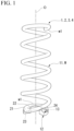
- a coil spring device 1 includes a main body spring 11 in which a wire rod W extends vertically in a spiral shape around a coil axis O and an insulator 12 which supports a lower end portion of the main body spring 11 from below the main body spring 11. That is, the vertical direction is the direction of the coil axis O.
- the coil spring device 1 is used by being mounted on, for example, a shock absorber inserted into the main body spring 11 and a suspension device having a strut mount mounted on the upper end of the shock absorber.
- the main body spring 11 is an open-end coil spring in which a terminated end portion w1 of the wire rod W is vertically separated from the wire rod W adjacent to the terminated end portion w1 on the inside of the direction of the coil axis O.
- the cross-sectional shape of the wire rod W is the same over the entire length including the terminated end portion w1. In the example shown in the drawings, the cross-sectional shape of the wire rod W is a circular shape.
- a closed-end coil spring in which the terminated end portion w1 of the wire rod W contacts and overlaps the wire rod W adjacent to the terminated end portion w1 on the inside of the direction of the coil axis O may be adopted as the main body spring 11.
- the terminated end portion w1 of the wire rod W may be subjected to, for example, grinding to form a flat surface extending in the horizontal direction orthogonal to the vertical direction and facing outward in the vertical direction.
- the cross-sectional shape of the wire rod W may be, for example, a rectangular shape or the like.
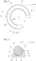
- the insulator 12 is made of an elastic material such as rubber. As shown in Fig. 2 , the insulator 12 has an arc shape extending around the coil axis O when viewed from the vertical direction. The insulator 12 extends over an angle range of 180° or more and 360° or less with respect to the coil axis O.
- the insulator 12 is provided with a support groove 13 which extends around the coil axis O and into which the lower end portion of the main body spring 11 is fitted.
- the support groove 13 extends over an angle range of 180° or more and 360° or less with respect to the coil axis O.
- an adhesive layer 16 is provided between an inner surface 13a of the support groove 13 and the lower end portion of the main body spring 11 and the lower end portion of the main body spring 11 adheres to the inner surface 13a of the support groove 13.
- the inner surface 13a of the support groove 13 is formed in a concave curved shape curved along the outer peripheral surface of the wire rod W.
- the support groove 13 integrally opens toward one side in the circumferential direction around the coil axis O, upward, and outward in the radial direction (direction orthogonal to the direction of the coil axis O).
- the support groove 13 for example, a configuration in which the support groove opens toward both circumferential sides, a configuration in which the radial outside of the support groove is closed, or the like may be adopted.
- Open end edges 21 to 24 of the support groove 13 include an outer peripheral edge 21 which is located at the radially outer end edge of the support groove 13 and extends around the coil axis O, an inner peripheral edge 22 which is located at the radially inner end edge of the support groove 13 and extends around the coil axis O, one end edge 23 which connects one end edges in the circumferential direction of the outer peripheral edge 21 and the inner peripheral edge 22, and the other end edge 24 which extends outward in the radial direction from the other end edge in the circumferential direction of the inner peripheral edge 22.
- the outer peripheral edge 21 is located below the inner peripheral edge 22.
- One end edge 23 has a concave curved shape curved along the outer peripheral surface of the wire rod W when viewed from one side in the circumferential direction.
- the inner surface 13a of the support groove 13 is provided with a plurality of spacer protrusions 14 and 15 which support the outer peripheral surface of the wire rod W.
- the plurality of spacer protrusions 14 and 15 are provided on the inner surface 13a of the support groove 13 at intervals therebetween in the circumferential direction and the radial direction.
- the plurality of spacer protrusions 14 and 15 are provided over the entire area of the inner surface 13a of the support groove 13.
- the ratio of the volume of the spacer protrusions 14 and 15 occupying a gap between the inner surface 13a of the support groove 13 and the outer peripheral surface of the wire rod W exceeds 10% and the ratio of the volume of the adhesive layer 16 occupying the gap is smaller than 90%.
- the adjacent spacer protrusion 14, which is adjacent to the open end edges 21 to 24 of the support groove 13, of the plurality of spacer protrusions 14 and 15 includes a pair of side wall surfaces 14a and 14b which extends toward the open end edges 21 to 24.
- the adjacent spacer protrusion 14 is adjacent to the outer peripheral edge 21 of the support groove 13 and the pair of side wall surfaces 14a and 14b of the adjacent spacer protrusion 14 extends toward the outer peripheral edge 21 of the support groove 13.
- the adjacent spacer protrusion 14 a configuration may be adopted in which the side wall surfaces 14a and 14b of the adjacent spacer protrusion 14 extend toward the other open end edges 22 to 24 of the support groove 13 to be adjacent to the other open end edges 22 to 24 other than the outer peripheral edge 21 in the open end edges 21 to 24 of the support groove 13.
- the spacer protrusion 15 other than the adjacent spacer protrusion 14 may be formed in, for example, a columnar shape or the like which does not include the pair of side wall surfaces 14a and 14b.
- a plurality of the adjacent spacer protrusions 14 are provided at intervals A in the extension direction of the outer peripheral edge 21 of the support groove 13 in the plan view (in a view in the direction of the coil axis O) of the part including the outer peripheral edge 21 of the support groove 13 in the inner surface 13a of the support groove 13.
- the extension direction is same as the circumferential direction.
- At least one of two adjacent spacer protrusions 14 adjacent to each other in the circumferential direction is formed so that the width of the one of two adjacent spacer protrusions 14 in the circumferential direction becomes narrower as it becomes closer to the outer peripheral edge 21 of the support groove 13 and the inclination angles ⁇ 1 and ⁇ 2 of the pair of side wall surfaces 14a and 14b of the one of two adjacent spacer protrusions 14 with respect to the orthogonal direction orthogonal to the outer peripheral edge 21 of the support groove 13 in the plan view are different from each other.
- the orthogonal direction is same as the radial direction.
- At least one of two adjacent spacer protrusions 14 adjacent to each other in the circumferential direction is formed so that the circumferential width of the one of two adjacent spacer protrusions 14 becomes narrower as it becomes closer to the outer peripheral edge 21 of the support groove 13, and includes a front wall surface 14c connecting the end portions of the pair of side wall surfaces 14a and 14b on the side of the outer peripheral edge 21 of the support groove 13 and facing the outer peripheral edge 21 of the support groove 13, and an intersection P1 of the extension lines L1 and L2 of the pair of side wall surfaces 14a and 14b are located on the inner surface 13a of the support groove 13 in the plan view. That is, the intersection P1 is located between the front wall surface 14c and the outer peripheral edge 21 of the support groove 13. Additionally, in the plan view, the intersection P1 may be located on the outside of the support groove 13.
- the plurality of adjacent spacer protrusions 14 are formed to have the same size and the same shape.
- the adjacent spacer protrusion 14 has a trapezoidal shape in which the front wall surface 14c forms an upper base and the pair of side wall surfaces 14a and 14b forms feet in the plan view.
- one side wall surface 14a of the pair of side wall surfaces 14a and 14b of each adjacent spacer protrusion 14 extends in a direction in which the one side wall surface 14a becomes closer to the other side wall surface 14b of the pair of side wall surfaces 14a and 14b as it becomes closer to the outer peripheral edge 21 of the support groove 13 and the other side wall surface 14b extends in a direction in which the other side wall surface 14b becomes farther from the one side wall surface 14a as it becomes closer to the outer peripheral edge 21 of the support groove 13.
- each adjacent spacer protrusion 14 may extend in a direction in which the side wall surfaces 14a and 14b become closer to each other in the circumferential direction as they become closer to the outer peripheral edge 21 of the support groove 13 in the plan view.
- the inclination angles ⁇ 1 and ⁇ 2 of the side wall surfaces 14a and 14b adjacent to each other in the circumferential direction with the interval A therebetween with respect to the radial direction are different from each other.
- the width of the interval A (the size in the circumferential direction) becomes wider as it becomes closer to the outer peripheral edge 21 of the support groove 13.
- the pair of side wall surfaces 14a and 14b extends straight in the plan view.
- the inclination angles ⁇ 1 and ⁇ 2 of the side wall surfaces 14a and 14b adjacent to each other in the circumferential direction with the interval A therebetween with respect to the radial direction in the plan view are different.
- the direction or speed of the flows of the adhesive can be made different between a side of the one side wall surface 14a and a side of the other side wall surface 14b defining the interval A in the process in which the adhesive placed on the side opposite to the outer peripheral edge 21 of the support groove 13 with the adjacent spacer protrusion 14 therebetween in the inner surface 13a of the support groove 13 flows toward the outer peripheral edge 21 of the support groove 13 while passing through the interval A.
- the adhesive flowing through the interval A is suppressed from reaching the outer peripheral edge 21 of the support groove 13 in a rectified state and it is possible to suppress the generation of the weld line on the outer surface of the adhesive layer 16 between the lower end portion of the main body spring 11 and the inner surface 13a of the support groove 13.
- At least one of two adjacent spacer protrusions 14 adjacent to each other in the circumferential direction is formed so that the width of the one of two adjacent spacer protrusions 14 becomes narrower as it becomes closer to the outer peripheral edge 21 of the support groove 13 and the inclination angles ⁇ 1 and ⁇ 2 of the pair of side wall surfaces 14a and 14b of the one of two adjacent spacer protrusions 14 with respect to the radial direction are different from each other in the plan view.
- the momentum of the flows can be weakened by causing two branch flows, that are generated by branching a flow by the adjacent spacer protrusion 14, to interfere with each other as one branch flow of the two branch flows divides the other branch flow of the two branch flows at the time of merging, for example, in the process in which the adhesive placed on the side opposite to the outer peripheral edge 21 of the support groove 13 with the adjacent spacer protrusion 14 therebetween in the inner surface 13a of the support groove 13 flows toward the outer peripheral edge 21 of the support groove 13 between the inner surface 13a of the support groove 13 and the outer peripheral surface of the wire rod W forming the lower end portion of the main body spring 11.
- two branch flows merge after merging are suppressed from reaching the outer peripheral edge 21 of the support groove 13 in the rectified state and it is possible to suppress the generation of the weld line, exposing a part of the outer peripheral edge 21 of the support groove 13 to straddle the radial direction, on the outer surface of the adhesive layer 16 between the lower end portion of the main body spring 11 and the inner surface 13a of the support groove 13.
- At least one of two adjacent spacer protrusions 14 adjacent to each other in the circumferential direction is formed so that the width of the one of two adjacent spacer protrusions 14 becomes narrower as it becomes closer to the outer peripheral edge 21 of the support groove 13, and includes the front wall surface 14c connecting the end portions of the pair of side wall surfaces 14a and 14b on the side of the outer peripheral edge 21 of the support groove 13 and facing the outer peripheral edge 21 of the support groove 13, and the intersection P1 between the extension lines L1 and L2 of the pair of side wall surfaces 14a and 14b are located on the inner surface 13a of the support groove 13 in the plan view.
- At least one of the two intervals A adjacent to each other in the circumferential direction becomes narrower as it becomes closer to the outer peripheral edge 21 of the support groove 13, and in the plan view, an intersection P2 of extension lines L2 of the side wall surfaces 14b adjacent to each other in the circumferential direction with the interval A therebetween is located on the inner surface 13a of the support groove 13. That is, the intersection P2 is located between the outer peripheral edge 21 of the support groove 13 and the front wall surface 14c.
- the adjacent spacer protrusions 14 adjacent to each other in the circumferential direction have a symmetrical shape with respect to a line extending in the radial direction through the center portion in the circumferential direction at the interval A in the plan view.
- the inclination angles ⁇ 1 of the side wall surfaces 14a adjacent to each other in the circumferential direction with the interval A therebetween with respect to the radial direction are the same as each other, and the inclination angles ⁇ 2 of the side wall surfaces 14b adjacent to each other in the circumferential direction with the interval A therebetween with respect to the radial direction are the same as each other.
- the interval A in which the width thereof becomes narrower as it becomes closer to the outer peripheral edge 21 of the support groove 13 and the interval A in which the width thereof becomes wider as it becomes closer to the outer peripheral edge 21 of the support groove 13 are alternately provided in the circumferential direction with the adjacent spacer protrusion 14 therebetween.
- the intersection P2 of the extension lines L2 of the side wall surfaces 14b defining the former interval A is located on the inner surface 13a of the support groove 13.
- the intersection P2 coincides with the intersection P1 of each of the adjacent spacer protrusions 14 sandwiching the former interval A in the circumferential direction in the plan view.
- the intersection P2 may be located on the outside of the support groove 13 or may be located away from the intersection P1. Further, the inclination angles ⁇ 1 of the side wall surfaces 14a adjacent to each other in the circumferential direction with the interval A therebetween with respect to the radial direction may be different from each other in the plan view, and the inclination angles ⁇ 2 of the side wall surfaces 14b adjacent to each other in the circumferential direction with the interval A therebetween with respect to the radial direction may be different from each other in the plan view.
- the intersection P2 of the extension lines L2 of the side wall surfaces 14b adjacent to each other in the circumferential direction with the interval A, becoming narrower as it becomes closer to the outer peripheral edge 21 of the support groove 13, therebetween is located on the inner surface 13a of the support groove 13 in the plan view.
- one adhesive flow flowing along one side wall surface 14b defining the interval A and the other adhesive flow flowing along the other side wall surface 14b defining the interval A can be merged at a position separated to the rear side in the flow direction from the outer peripheral edge 21 of the support groove 13 (a position separated to inside in the radial direction from the outer peripheral edge 21).
- the momentum of the flows when these two flows reach the outer peripheral edge 21 of the support groove 13 is suppressed and the generation of the weld line on the outer surface of the adhesive layer 16 can be reliably suppressed.
- the same parts as the components in the first embodiment are designated by the same reference numerals, the description thereof is omitted, and only the different points are described.
- the adjacent spacer protrusion 14 does not include the front wall surface 14c and has a triangular shape sharpened toward the outer peripheral edge 21 side of the support groove 13 in the plan view.
- the pair of side wall surfaces 14a and 14b of each adjacent spacer protrusion 14 extend in a direction in which the pair of side wall surfaces 14a and 14b become closer to each other in the circumferential direction as it becomes closer to the outer peripheral edge 21 of the support groove 13 in the plan view.
- the operation and effect are almost the same as the coil spring device 1 of the first embodiment.
- the inclination angles ⁇ 1 and ⁇ 2 of the side wall surfaces 14a and 14b adjacent to each other in the circumferential direction with the interval A therebetween with respect to the radial direction are different from each other in the plan view.
- each adjacent spacer protrusion 14 has a parallel quadrilateral shape in the plan view.
- planar shape of the adjacent spacer protrusion 14 is not limited to the parallel quadrilateral shape and may be appropriately changed. Further, the inclination angles ⁇ 1 or ⁇ 2 of the pair of side wall surfaces 14a and 14b of each adjacent spacer protrusion 14 with respect to the radial direction may be different from each other in the plan view.
- At least one of the two intervals A adjacent to each other in the circumferential direction becomes narrower as it becomes closer to the outer peripheral edge 21 of the support groove 13.
- the interval A in which the width thereof becomes narrower as it becomes closer to the outer peripheral edge 21 of the support groove 13 and the interval A in which the width thereof becomes wider as it becomes closer to the outer peripheral edge 21 of the support groove 13 are alternately provided in the circumferential direction with the adjacent spacer protrusion 14 therebetween.
- the intersection P2 of the extension lines L1 and L2 of the side wall surfaces 14a and 14b defining the former interval A is located on the inner surface 13a of the support groove 13. That is, the intersection P2 is located between the outer peripheral edge 21 of the support groove 13 and the front wall surface 14c. Additionally, the intersection P2 may be located on the outside of the support groove 13 in the plan view.
- the inclination angles ⁇ 1 and ⁇ 2 of the side wall surfaces 14a and 14b adjacent to each other in the circumferential direction with the interval A therebetween with respect to the radial direction are different from each other in the plan view.
- the direction or speed of the flows of the adhesive can be made different between a side of one side wall surface 14a and a side of the other side wall surface 14b defining the interval A in the process in which the adhesive on the inner surface 13a of the support groove 13 flows toward the outer peripheral edge 21 of the support groove 13 while passing through the interval A.
- the momentum of the flows can be weakened by causing two branch flows to interfere with each other as one branch flow flowing along one side wall surface 14a divides the other branch flow flowing along the other side wall surface 14b at the time of merging.
- one adhesive flow flowing along one side wall surface 14a defining the interval A and the other adhesive flow flowing along the other side wall surface 14b defining the interval A can be merged at a position separated to the rear side in the flow direction from the outer peripheral edge 21 of the support groove 13 (a position separated to inside in the radial direction from the outer peripheral edge 21) when the lower end portion of the main body spring 11 adheres to the inner surface 13a of the support groove 13. Accordingly, the momentum of the flows when these two flows reach the outer peripheral edge 21 of the support groove 13 is suppressed and the generation of the weld line on the outer surface of the adhesive layer 16 can be reliably suppressed.
- the pair of side wall surfaces 14a and 14b may be curved in the plan view and the planar shape of the adjacent spacer protrusion 14 may be a shape with chamfered corners, an oval shape, or the like.
- the adjacent spacer protrusion 14 may be provided over the entire length of the inner surface 13a of the support groove 13 in the radial direction.
- one of the two adjacent spacer protrusions 14 adjacent to each other in the circumferential direction may be provided in a direction rotating about the center of the figure thereof by 180° in the plan view so that the width of the one of the two adjacent spacer protrusions 14 becomes wider as it becomes closer to the outer peripheral edge 21 of the support groove 13.
- the side wall surfaces 14a adjacent to each other in the circumferential direction with the interval A therebetween may be made parallel to each other in the plan view
- the side wall surfaces 14b adjacent to each other in the circumferential direction with the interval A therebetween may be made parallel to each other in the plan view.
- the inclination angles ⁇ 1 of the side wall surfaces 14a with the interval A therebetween with respect to the radial direction may be the same as each other, and the inclination angles ⁇ 2 of the side wall surfaces 14b with the interval A therebetween with respect to the radial direction may be the same as each other.
- the present invention can be used in a coil spring device including a main body spring and an insulator including a support groove provided with a plurality of spacer protrusions.
Landscapes
- Engineering & Computer Science (AREA)
- General Engineering & Computer Science (AREA)
- Mechanical Engineering (AREA)
- Physics & Mathematics (AREA)
- Acoustics & Sound (AREA)
- Aviation & Aerospace Engineering (AREA)
- Springs (AREA)
- Fluid-Damping Devices (AREA)
Abstract
Description
- The present invention relates to a coil spring device.
- Priority is claimed on
Japanese Patent Application No. 2020-064890, filed March 31, 2020 - As a coil spring device that is used by being mounted on a suspension device, conventionally, a coil spring device including a main body spring in which a wire rod extends vertically in a spiral shape around a coil axis and an insulator which supports a lower end portion of the main body spring from below the main body spring is known. Here, the insulator is provided with a support groove which extends around a coil axis and into which the lower end portion of the main body spring is fitted, the lower end portion of the main body spring adheres to an inner surface of the support groove, and the inner surface of the support groove is provided with a plurality of spacer protrusions supporting an outer peripheral surface of the wire rod.
- When the lower end portion of the main body spring adheres to the inner surface of the support groove, an adhesive is first placed on the inner surface of the support groove and then the lower end portion of the main body spring is pressed into the support groove to spread the adhesive on the inner surface of the support groove.
- [Patent Document 1]
Japanese Unexamined Patent Application, First Publication No. 2017-15249 - However, in the conventional coil spring device, in the process in which the adhesive on the inner surface of the support groove is pressed into the lower end portion of the main body spring to flow toward the open end edge of the support groove, the flow is merged after branching by the spacer protrusion and reaches the open end edge of the support groove in the rectified state. Accordingly, there is a possibility that a weld line to be exposed that straddles a part of the open end edge of the support groove may be generated on the outer surface of the adhesive layer between the lower end portion of the main body spring and the inner surface of the support groove. In this case, since a part of the open end portion continuous to the open end edge in the inner surface of the support groove is exposed, there is a possibility that foreign substances such as small stones may enter this portion.
- The present invention is made in view of the above-described circumstances and an object of the present invention is to provide a coil spring device capable of suppressing a weld line from being generated on an outer surface of an adhesive layer between a lower end portion of a main body spring and an inner surface of a support groove.
- In order to solve the above-described problems and achieve such an object, a coil spring device according to a first aspect of the present invention includes: a main body spring in which a wire rod extends vertically in a spiral shape around a coil axis; and an insulator which supports a lower end portion of the main body spring from below the main body spring, wherein the insulator is provided with a support groove which extends around the coil axis and into which the lower end portion of the main body spring is fitted, wherein the lower end portion of the main body spring adheres to an inner surface of the support groove, wherein the inner surface of the support groove is provided with a plurality of spacer protrusions which support an outer peripheral surface of the wire rod, wherein a plurality of adj acent spacer protrusions adjacent to an open end edge of the support groove of the plurality of spacer protrusions each includes a pair of side wall surfaces extending toward the open end edge and are provided at intervals therebetween in an extension direction of the open end edge in a plan view of a part including the open end edge in the inner surface of the support groove, and wherein inclination angles of the side wall surfaces adjacent to each other in the extension direction with the interval therebetween with respect to an orthogonal direction orthogonal to the open end edge are different from each other in the plan view.
- According to the present invention, since the inclination angles of the side wall surfaces adjacent to each other in the extension direction with the interval therebetween with respect to the orthogonal direction are different from each other in the plan view, for example, the direction or speed of the flow of the adhesive can be made different between one side wall surface and the other side wall surface defining the interval in the process in which the adhesive placed on the side opposite to the open end edge of the support groove with the adjacent spacer protrusion therebetween in the inner surface of the support groove flows toward the open end edge of the support groove while passing through the interval when the lower end portion of the main body spring adheres to the inner surface of the support groove. Further, when the interval becomes narrower as it becomes closer to the open end edge, the momentum of the flows can be weakened by causing two branch flows to interfere with each other as one branch flow flowing along one side wall surface divides the other branch flow flowing along the other side wall surface at the time of merging.
- With the above-described configuration, the adhesive flowing through the interval is suppressed from reaching the open end edge of the support groove in the rectified state and it is possible to suppress the generation of the weld line to be exposed that straddles a part of the open end edge of the support groove in the orthogonal direction on the outer surface of the adhesive layer between the lower end portion of the main body spring and the inner surface of the support groove.
- A second aspect of the present invention is a coil spring device, wherein in the coil spring device of the first aspect, at least one of the two adjacent spacer protrusions adjacent to each other in the extension direction is formed so that a width of the one of the two adjacent spacer protrusions in the extension direction becomes narrower as it becomes closer to the open end edge and inclination angles of the pair of side wall surfaces of the one of the two adjacent spacer protrusions with respect to the orthogonal direction are different from each other in the plan view.
- In this case, at least one of the two adjacent spacer protrusions adjacent to each other in the extension direction is formed so that the width of the one of the two adjacent spacer protrusions in the extension direction becomes narrower as it becomes closer to the open end edge and the inclination angles of the pair of side wall surfaces of the one of the two adjacent spacer protrusions with respect to the orthogonal direction are different from each other in the plan view.
- Thus, when the lower end portion of the main body spring adheres to the inner surface of the support groove, the momentum of flows can be weakened by causing two branch flows generated by branching a flow of the adhesive by the adjacent spacer protrusion to interfere with each other as one branch flow of the two branch flows divides the other branch flow of the two branch flows at the time of merging, for example, in the process in which the adhesive placed on the opposite side to the open end edge of the support groove with the adjacent spacer protrusion therebetween in the inner surface of the support groove flows toward the open end edge of the support groove between the inner surface of the support groove and the outer peripheral surface of the wire rod forming the lower end portion of the main body spring. Accordingly, two branch flows after merging are suppressed from reaching the open end edge of the support groove in the rectified state and it is possible to suppress the generation of the weld line to be exposed that straddles a part of the open end edge of the support groove in the orthogonal direction, on the outer surface of the adhesive layer between the lower end portion of the main body spring and the inner surface of the support groove.
- A third aspect of the present invention is a coil spring device, wherein, in the coil spring device of the first or second aspect, at least one of the two adjacent spacer protrusions adjacent to each other in the extension direction is formed so that a width of the one of the two adjacent spacer protrusions in the extension direction becomes narrower as it becomes closer to the open end edge, and includes a front wall surface connecting end portions of the pair of side wall surfaces on the side of the open end edge and facing the open end edge, and an intersection of extension lines of the pair of side wall surfaces of the one of the two adjacent spacer protrusions is located on the inner surface of the support groove in the plan view.
- In this case, when the lower end portion of the main body spring adheres to the inner surface of the support groove, two adhesive branch flows generated by branching a flow of the adhesive by the adjacent spacer protrusion as described above can be merged at a position separated to the rear side in the flow direction from the open end edge of the support groove. Accordingly, the momentum of the flows when these two branch flows reach the open end edge of the support groove is suppressed, and the generation of the weld line on the outer surface of the adhesive layer can then be reliably suppressed.
- A fourth aspect of the present invention is a coil spring device, wherein, in the coil spring device of any one of the first to third aspects, at least one of the two intervals adjacent to each other in the extension direction becomes narrower as it becomes closer to the open end edge, and wherein an intersection of the extension lines of the side wall surfaces adjacent to each other in the extension direction with the interval therebetween in the plan view is located on the inner surface of the support groove.
- In this case, since the intersection of the extension lines of the side wall surfaces adjacent to each other in the extension direction with the interval therebetween becoming narrower as it becomes closer to the open end edge is located on the inner surface of the support groove in the plan view, one adhesive flow flowing along one side wall surface defining the interval and the other adhesive flow flowing the other side wall surface defining the interval can be merged at a position separated to the rear side in the flow direction from the open end edge of the support groove when the lower end portion of the main body spring adheres to the inner surface of the support groove. Accordingly, the momentum of the flows when these two flows reach the open end edge of the support groove is suppressed and the generation of the weld line on the outer surface of the adhesive layer can then be reliably suppressed.
- According to the present invention, it is possible to suppress a weld line from being generated on an outer surface of an adhesive layer between a lower end portion of a main body spring and an inner surface of a support groove.
-
-
Fig. 1 is a perspective view of a coil spring device according to an embodiment of the present invention. -
Fig. 2 is a plan view showing a part of the coil spring device ofFig. 1 . -
Fig. 3 is a cross-sectional view taken along a line III-III of the coil spring device shown inFig. 2 . -
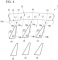
Fig. 4 is a plan view of a part including an outer peripheral edge of a support groove in an inner surface of the support groove shown as a first embodiment according to the present invention. -
Fig. 5 is a plan view of a part including an outer peripheral edge of a support groove in an inner surface of the support groove shown as a second embodiment according to the present invention. -
Fig. 6 is a plan view of a part including an outer peripheral edge of a support groove in an inner surface of the support groove shown as a third embodiment according to the present invention. -
Fig. 7 is a plan view of a part including an outer peripheral edge of a support groove in an inner surface of the support groove shown as a fourth embodiment according to the present invention. -
Fig. 8 is a plan view of a part including an outer peripheral edge of a support groove in an inner surface of the support groove shown as modified examples of the first embodiment and the third embodiment according to the present invention. - Hereinafter, a first embodiment of a coil spring device according to the present invention is described with reference to
Figs. 1 to 4 . - A
coil spring device 1 includes amain body spring 11 in which a wire rod W extends vertically in a spiral shape around a coil axis O and aninsulator 12 which supports a lower end portion of themain body spring 11 from below themain body spring 11. That is, the vertical direction is the direction of the coil axis O. Thecoil spring device 1 is used by being mounted on, for example, a shock absorber inserted into themain body spring 11 and a suspension device having a strut mount mounted on the upper end of the shock absorber. - The
main body spring 11 is an open-end coil spring in which a terminated end portion w1 of the wire rod W is vertically separated from the wire rod W adjacent to the terminated end portion w1 on the inside of the direction of the coil axis O. The cross-sectional shape of the wire rod W is the same over the entire length including the terminated end portion w1. In the example shown in the drawings, the cross-sectional shape of the wire rod W is a circular shape. - Additionally, a closed-end coil spring in which the terminated end portion w1 of the wire rod W contacts and overlaps the wire rod W adjacent to the terminated end portion w1 on the inside of the direction of the coil axis O may be adopted as the
main body spring 11. In this configuration, the terminated end portion w1 of the wire rod W may be subjected to, for example, grinding to form a flat surface extending in the horizontal direction orthogonal to the vertical direction and facing outward in the vertical direction. The cross-sectional shape of the wire rod W may be, for example, a rectangular shape or the like. - The
insulator 12 is made of an elastic material such as rubber. As shown inFig. 2 , theinsulator 12 has an arc shape extending around the coil axis O when viewed from the vertical direction. Theinsulator 12 extends over an angle range of 180° or more and 360° or less with respect to the coil axis O. - The
insulator 12 is provided with asupport groove 13 which extends around the coil axis O and into which the lower end portion of themain body spring 11 is fitted. Thesupport groove 13 extends over an angle range of 180° or more and 360° or less with respect to the coil axis O. As shown inFig. 3 , anadhesive layer 16 is provided between aninner surface 13a of thesupport groove 13 and the lower end portion of themain body spring 11 and the lower end portion of themain body spring 11 adheres to theinner surface 13a of thesupport groove 13. - The
inner surface 13a of thesupport groove 13 is formed in a concave curved shape curved along the outer peripheral surface of the wire rod W. Thesupport groove 13 integrally opens toward one side in the circumferential direction around the coil axis O, upward, and outward in the radial direction (direction orthogonal to the direction of the coil axis O). - Additionally, as the
support groove 13, for example, a configuration in which the support groove opens toward both circumferential sides, a configuration in which the radial outside of the support groove is closed, or the like may be adopted. -
Open end edges 21 to 24 of thesupport groove 13 include an outerperipheral edge 21 which is located at the radially outer end edge of thesupport groove 13 and extends around the coil axis O, an innerperipheral edge 22 which is located at the radially inner end edge of thesupport groove 13 and extends around the coil axis O, oneend edge 23 which connects one end edges in the circumferential direction of the outerperipheral edge 21 and the innerperipheral edge 22, and theother end edge 24 which extends outward in the radial direction from the other end edge in the circumferential direction of the innerperipheral edge 22. - The outer
peripheral edge 21 is located below the innerperipheral edge 22. Oneend edge 23 has a concave curved shape curved along the outer peripheral surface of the wire rod W when viewed from one side in the circumferential direction. - The
inner surface 13a of thesupport groove 13 is provided with a plurality ofspacer protrusions - The plurality of
spacer protrusions inner surface 13a of thesupport groove 13 at intervals therebetween in the circumferential direction and the radial direction. The plurality ofspacer protrusions inner surface 13a of thesupport groove 13. The ratio of the volume of thespacer protrusions inner surface 13a of thesupport groove 13 and the outer peripheral surface of the wire rod W exceeds 10% and the ratio of the volume of theadhesive layer 16 occupying the gap is smaller than 90%. - As shown in
Fig. 4 , theadjacent spacer protrusion 14, which is adjacent to the open end edges 21 to 24 of thesupport groove 13, of the plurality ofspacer protrusions adjacent spacer protrusion 14 is adjacent to the outerperipheral edge 21 of thesupport groove 13 and the pair of side wall surfaces 14a and 14b of theadjacent spacer protrusion 14 extends toward the outerperipheral edge 21 of thesupport groove 13. - Additionally, as the
adjacent spacer protrusion 14, a configuration may be adopted in which the side wall surfaces 14a and 14b of theadjacent spacer protrusion 14 extend toward the other open end edges 22 to 24 of thesupport groove 13 to be adjacent to the other open end edges 22 to 24 other than the outerperipheral edge 21 in the open end edges 21 to 24 of thesupport groove 13. In the plurality ofspacer protrusions spacer protrusion 15 other than theadjacent spacer protrusion 14 may be formed in, for example, a columnar shape or the like which does not include the pair of side wall surfaces 14a and 14b. - As shown in
Fig. 4 , a plurality of theadjacent spacer protrusions 14 are provided at intervals A in the extension direction of the outerperipheral edge 21 of thesupport groove 13 in the plan view (in a view in the direction of the coil axis O) of the part including the outerperipheral edge 21 of thesupport groove 13 in theinner surface 13a of thesupport groove 13. - In the example shown in the drawing, the extension direction is same as the circumferential direction.
- Then, at least one of two
adjacent spacer protrusions 14 adjacent to each other in the circumferential direction is formed so that the width of the one of twoadjacent spacer protrusions 14 in the circumferential direction becomes narrower as it becomes closer to the outerperipheral edge 21 of thesupport groove 13 and the inclination angles θ1 and Θ2 of the pair of side wall surfaces 14a and 14b of the one of twoadjacent spacer protrusions 14 with respect to the orthogonal direction orthogonal to the outerperipheral edge 21 of thesupport groove 13 in the plan view are different from each other. - In the example shown in the drawing, the orthogonal direction is same as the radial direction.
- Further, at least one of two
adjacent spacer protrusions 14 adjacent to each other in the circumferential direction is formed so that the circumferential width of the one of twoadjacent spacer protrusions 14 becomes narrower as it becomes closer to the outerperipheral edge 21 of thesupport groove 13, and includes afront wall surface 14c connecting the end portions of the pair of side wall surfaces 14a and 14b on the side of the outerperipheral edge 21 of thesupport groove 13 and facing the outerperipheral edge 21 of thesupport groove 13, and an intersection P1 of the extension lines L1 and L2 of the pair of side wall surfaces 14a and 14b are located on theinner surface 13a of thesupport groove 13 in the plan view. That is, the intersection P1 is located between thefront wall surface 14c and the outerperipheral edge 21 of thesupport groove 13. Additionally, in the plan view, the intersection P1 may be located on the outside of thesupport groove 13. - In the example shown in the drawing, the plurality of
adjacent spacer protrusions 14 are formed to have the same size and the same shape. - The
adjacent spacer protrusion 14 has a trapezoidal shape in which thefront wall surface 14c forms an upper base and the pair of side wall surfaces 14a and 14b forms feet in the plan view. In the plan view, oneside wall surface 14a of the pair of side wall surfaces 14a and 14b of eachadjacent spacer protrusion 14 extends in a direction in which the oneside wall surface 14a becomes closer to the otherside wall surface 14b of the pair of side wall surfaces 14a and 14b as it becomes closer to the outerperipheral edge 21 of thesupport groove 13 and the otherside wall surface 14b extends in a direction in which the otherside wall surface 14b becomes farther from the oneside wall surface 14a as it becomes closer to the outerperipheral edge 21 of thesupport groove 13. - Additionally, the pair of side wall surfaces 14a and 14b of each
adjacent spacer protrusion 14 may extend in a direction in which the side wall surfaces 14a and 14b become closer to each other in the circumferential direction as they become closer to the outerperipheral edge 21 of thesupport groove 13 in the plan view. - In the plan view, the inclination angles θ1 and θ2 of the side wall surfaces 14a and 14b adjacent to each other in the circumferential direction with the interval A therebetween with respect to the radial direction are different from each other. The width of the interval A (the size in the circumferential direction) becomes wider as it becomes closer to the outer
peripheral edge 21 of thesupport groove 13. The pair of side wall surfaces 14a and 14b extends straight in the plan view. - As described above, according to the
coil spring device 1 of this embodiment, the inclination angles θ1 and θ2 of the side wall surfaces 14a and 14b adjacent to each other in the circumferential direction with the interval A therebetween with respect to the radial direction in the plan view are different. - Thus, when the lower end portion of the
main body spring 11 adheres to theinner surface 13a of thesupport groove 13, for example, the direction or speed of the flows of the adhesive can be made different between a side of the oneside wall surface 14a and a side of the otherside wall surface 14b defining the interval A in the process in which the adhesive placed on the side opposite to the outerperipheral edge 21 of thesupport groove 13 with theadjacent spacer protrusion 14 therebetween in theinner surface 13a of thesupport groove 13 flows toward the outerperipheral edge 21 of thesupport groove 13 while passing through the interval A. - Accordingly, the adhesive flowing through the interval A is suppressed from reaching the outer
peripheral edge 21 of thesupport groove 13 in a rectified state and it is possible to suppress the generation of the weld line on the outer surface of theadhesive layer 16 between the lower end portion of themain body spring 11 and theinner surface 13a of thesupport groove 13. - In this embodiment, at least one of two
adjacent spacer protrusions 14 adjacent to each other in the circumferential direction is formed so that the width of the one of twoadjacent spacer protrusions 14 becomes narrower as it becomes closer to the outerperipheral edge 21 of thesupport groove 13 and the inclination angles Θ1 and Θ2 of the pair of side wall surfaces 14a and 14b of the one of twoadjacent spacer protrusions 14 with respect to the radial direction are different from each other in the plan view. - Thus, when the lower end portion of the
main body spring 11 adheres to theinner surface 13a of thesupport groove 13, the momentum of the flows can be weakened by causing two branch flows, that are generated by branching a flow by theadjacent spacer protrusion 14, to interfere with each other as one branch flow of the two branch flows divides the other branch flow of the two branch flows at the time of merging, for example, in the process in which the adhesive placed on the side opposite to the outerperipheral edge 21 of thesupport groove 13 with theadjacent spacer protrusion 14 therebetween in theinner surface 13a of thesupport groove 13 flows toward the outerperipheral edge 21 of thesupport groove 13 between theinner surface 13a of thesupport groove 13 and the outer peripheral surface of the wire rod W forming the lower end portion of themain body spring 11. Accordingly, two branch flows merge after merging are suppressed from reaching the outerperipheral edge 21 of thesupport groove 13 in the rectified state and it is possible to suppress the generation of the weld line, exposing a part of the outerperipheral edge 21 of thesupport groove 13 to straddle the radial direction, on the outer surface of theadhesive layer 16 between the lower end portion of themain body spring 11 and theinner surface 13a of thesupport groove 13. - In this embodiment, at least one of two
adjacent spacer protrusions 14 adjacent to each other in the circumferential direction is formed so that the width of the one of twoadjacent spacer protrusions 14 becomes narrower as it becomes closer to the outerperipheral edge 21 of thesupport groove 13, and includes thefront wall surface 14c connecting the end portions of the pair of side wall surfaces 14a and 14b on the side of the outerperipheral edge 21 of thesupport groove 13 and facing the outerperipheral edge 21 of thesupport groove 13, and the intersection P1 between the extension lines L1 and L2 of the pair of side wall surfaces 14a and 14b are located on theinner surface 13a of thesupport groove 13 in the plan view. - Thus, when the lower end portion of the
main body spring 11 adheres to theinner surface 13a of thesupport groove 13, two adhesive branch flows generated by branching the flow by theadjacent spacer protrusion 14 as described above can be merged at a position separated towards the rear side in the flow direction from the outerperipheral edge 21 of the support groove 13 (a position separated to the inside in the radial direction from the outer peripheral edge 21). Accordingly, the momentum of the flows when these two branch flows reach the outerperipheral edge 21 of thesupport groove 13 is suppressed and the generation of the weld line on the outer surface of theadhesive layer 16 can be reliably suppressed. - Next, a
coil spring device 2 according to a second embodiment of the present invention is described with reference toFig. 5 . - Additionally, in the second embodiment, the same parts as the components in the first embodiment are designated by the same reference numerals, the description thereof is omitted, and only the different points are described.
- In the
coil spring device 2 of this embodiment, at least one of the two intervals A adjacent to each other in the circumferential direction becomes narrower as it becomes closer to the outerperipheral edge 21 of thesupport groove 13, and in the plan view, an intersection P2 of extension lines L2 of the side wall surfaces 14b adjacent to each other in the circumferential direction with the interval A therebetween is located on theinner surface 13a of thesupport groove 13. That is, the intersection P2 is located between the outerperipheral edge 21 of thesupport groove 13 and thefront wall surface 14c. - In the example shown in the drawing, the
adjacent spacer protrusions 14 adjacent to each other in the circumferential direction have a symmetrical shape with respect to a line extending in the radial direction through the center portion in the circumferential direction at the interval A in the plan view. In the plan view, the inclination angles θ1 of the side wall surfaces 14a adjacent to each other in the circumferential direction with the interval A therebetween with respect to the radial direction are the same as each other, and the inclination angles θ2 of the side wall surfaces 14b adjacent to each other in the circumferential direction with the interval A therebetween with respect to the radial direction are the same as each other. The interval A in which the width thereof becomes narrower as it becomes closer to the outerperipheral edge 21 of thesupport groove 13 and the interval A in which the width thereof becomes wider as it becomes closer to the outerperipheral edge 21 of thesupport groove 13 are alternately provided in the circumferential direction with theadjacent spacer protrusion 14 therebetween. In the plan view, the intersection P2 of the extension lines L2 of the side wall surfaces 14b defining the former interval A (the interval A having a width that becomes narrower as it becomes closer to the outerperipheral edge 21 of the support groove 13) is located on theinner surface 13a of thesupport groove 13. The intersection P2 coincides with the intersection P1 of each of theadjacent spacer protrusions 14 sandwiching the former interval A in the circumferential direction in the plan view. - Additionally, in the plan view, the intersection P2 may be located on the outside of the
support groove 13 or may be located away from the intersection P1. Further, the inclination angles θ1 of the side wall surfaces 14a adjacent to each other in the circumferential direction with the interval A therebetween with respect to the radial direction may be different from each other in the plan view, and the inclination angles Θ2 of the side wall surfaces 14b adjacent to each other in the circumferential direction with the interval A therebetween with respect to the radial direction may be different from each other in the plan view. - As described above, according to the
coil spring device 2 of this embodiment, the intersection P2 of the extension lines L2 of the side wall surfaces 14b adjacent to each other in the circumferential direction with the interval A, becoming narrower as it becomes closer to the outerperipheral edge 21 of thesupport groove 13, therebetween is located on theinner surface 13a of thesupport groove 13 in the plan view. Accordingly, when the lower end portion of themain body spring 11 adheres to theinner surface 13a of thesupport groove 13, one adhesive flow flowing along oneside wall surface 14b defining the interval A and the other adhesive flow flowing along the otherside wall surface 14b defining the interval A can be merged at a position separated to the rear side in the flow direction from the outerperipheral edge 21 of the support groove 13 (a position separated to inside in the radial direction from the outer peripheral edge 21). Thus, the momentum of the flows when these two flows reach the outerperipheral edge 21 of thesupport groove 13 is suppressed and the generation of the weld line on the outer surface of theadhesive layer 16 can be reliably suppressed. - Next, a
coil spring device 3 according to a third embodiment of the present invention is described with reference toFig. 6 . - Additionally, in the third embodiment, the same parts as the components in the first embodiment are designated by the same reference numerals, the description thereof is omitted, and only the different points are described.
- In the
coil spring device 3 of this embodiment, theadjacent spacer protrusion 14 does not include thefront wall surface 14c and has a triangular shape sharpened toward the outerperipheral edge 21 side of thesupport groove 13 in the plan view. In the example shown in the drawing, the pair of side wall surfaces 14a and 14b of eachadjacent spacer protrusion 14 extend in a direction in which the pair of side wall surfaces 14a and 14b become closer to each other in the circumferential direction as it becomes closer to the outerperipheral edge 21 of thesupport groove 13 in the plan view. - As described above, according to the
coil spring device 3 of this embodiment, the operation and effect are almost the same as thecoil spring device 1 of the first embodiment. - Next, a
coil spring device 4 according to a fourth embodiment of the present invention is described with reference toFig. 7 . - Additionally, in the fourth embodiment, the same parts as the components in the first embodiment are designated by the same reference numerals, the description thereof is omitted, and only the different points are described.
- In the
coil spring device 4 of this embodiment, the inclination angles Θ1 and Θ2 of the side wall surfaces 14a and 14b adjacent to each other in the circumferential direction with the interval A therebetween with respect to the radial direction are different from each other in the plan view. - The inclination angles Θ1 or Θ2 of the pair of side wall surfaces 14a and 14b of each
adjacent spacer protrusion 14 with respect to the radial direction are the same as each other in the plan view. In the example shown in the drawing, theadjacent spacer protrusion 14 has a parallel quadrilateral shape in the plan view. - Additionally, the planar shape of the
adjacent spacer protrusion 14 is not limited to the parallel quadrilateral shape and may be appropriately changed. Further, the inclination angles θ1 or θ2 of the pair of side wall surfaces 14a and 14b of eachadjacent spacer protrusion 14 with respect to the radial direction may be different from each other in the plan view. - At least one of the two intervals A adjacent to each other in the circumferential direction becomes narrower as it becomes closer to the outer
peripheral edge 21 of thesupport groove 13. In the example shown in the drawing, the interval A in which the width thereof becomes narrower as it becomes closer to the outerperipheral edge 21 of thesupport groove 13 and the interval A in which the width thereof becomes wider as it becomes closer to the outerperipheral edge 21 of thesupport groove 13 are alternately provided in the circumferential direction with theadjacent spacer protrusion 14 therebetween. In the plan view, the intersection P2 of the extension lines L1 and L2 of the side wall surfaces 14a and 14b defining the former interval A is located on theinner surface 13a of thesupport groove 13. That is, the intersection P2 is located between the outerperipheral edge 21 of thesupport groove 13 and thefront wall surface 14c. Additionally, the intersection P2 may be located on the outside of thesupport groove 13 in the plan view. - As described above, according to the
coil spring device 4 of this embodiment, the inclination angles θ1 and θ2 of the side wall surfaces 14a and 14b adjacent to each other in the circumferential direction with the interval A therebetween with respect to the radial direction are different from each other in the plan view. - Thus, when the lower end portion of the
main body spring 11 adheres to theinner surface 13a of thesupport groove 13, for example, the direction or speed of the flows of the adhesive can be made different between a side of oneside wall surface 14a and a side of the otherside wall surface 14b defining the interval A in the process in which the adhesive on theinner surface 13a of thesupport groove 13 flows toward the outerperipheral edge 21 of thesupport groove 13 while passing through the interval A. Further, when the interval A becomes narrower as it becomes closer to the outerperipheral edge 21 of thesupport groove 13, the momentum of the flows can be weakened by causing two branch flows to interfere with each other as one branch flow flowing along oneside wall surface 14a divides the other branch flow flowing along the otherside wall surface 14b at the time of merging. - With the above-described configuration, it is suppressed that the adhesive flowing through the interval A reaches the outer
peripheral edge 21 of thesupport groove 13 in the rectified state and it is possible to suppress the generation of the weld line on the outer surface of theadhesive layer 16. - Since the intersection P2 of the extension lines L1 and L2 of the side wall surfaces 14a and 14b adjacent to each other in the circumferential direction with the interval A, becoming narrower as it becomes closer to the outer
peripheral edge 21 of thesupport groove 13, therebetween is located on theinner surface 13a of thesupport groove 13 in the plan view, one adhesive flow flowing along oneside wall surface 14a defining the interval A and the other adhesive flow flowing along the otherside wall surface 14b defining the interval A can be merged at a position separated to the rear side in the flow direction from the outerperipheral edge 21 of the support groove 13 (a position separated to inside in the radial direction from the outer peripheral edge 21) when the lower end portion of themain body spring 11 adheres to theinner surface 13a of thesupport groove 13. Accordingly, the momentum of the flows when these two flows reach the outerperipheral edge 21 of thesupport groove 13 is suppressed and the generation of the weld line on the outer surface of theadhesive layer 16 can be reliably suppressed. - Additionally, the technical scope of the present invention is not limited to the embodiments described above, and various modifications can be made without departing from the objective of the present invention.
- For example, the pair of side wall surfaces 14a and 14b may be curved in the plan view and the planar shape of the
adjacent spacer protrusion 14 may be a shape with chamfered corners, an oval shape, or the like. - The
adjacent spacer protrusion 14 may be provided over the entire length of theinner surface 13a of thesupport groove 13 in the radial direction. - In the first embodiment or the third embodiment, for example, as shown in
Fig. 8 , one of the twoadjacent spacer protrusions 14 adjacent to each other in the circumferential direction may be provided in a direction rotating about the center of the figure thereof by 180° in the plan view so that the width of the one of the twoadjacent spacer protrusions 14 becomes wider as it becomes closer to the outerperipheral edge 21 of thesupport groove 13. In this case, the side wall surfaces 14a adjacent to each other in the circumferential direction with the interval A therebetween may be made parallel to each other in the plan view, and the side wall surfaces 14b adjacent to each other in the circumferential direction with the interval A therebetween may be made parallel to each other in the plan view. Also, in this case, the inclination angles Θ1 of the side wall surfaces 14a with the interval A therebetween with respect to the radial direction may be the same as each other, and the inclination angles Θ2 of the side wall surfaces 14b with the interval A therebetween with respect to the radial direction may be the same as each other. - In addition, the constituent elements in the above-described embodiment can be appropriately replaced with well-known constituent elements without departing from the objective of the present invention, and the embodiments described above, and modified example may be appropriately combined.
- The present invention can be used in a coil spring device including a main body spring and an insulator including a support groove provided with a plurality of spacer protrusions.
-
- 1, 2, 3, 4 Coil spring device
- 11 Main body spring
- 12 Insulator
- 13 Support groove
- 14 Adjacent spacer protrusion (spacer protrusion)
- 14a, 14b Side wall surface
- 14c Front wall surface
- 21 Outer peripheral edge (open end edge)
- A Interval
- L1, L2 Extension line
- O Coil axis
- P1, P2 Intersection
- W Wire rod
- θ1, θ2 Inclination angle
Claims (4)
- A coil spring device comprising:a main body spring in which a wire rod extends vertically in a spiral shape around a coil axis; andan insulator which supports a lower end portion of the main body spring from below the main body spring,wherein the insulator is provided with a support groove which extends around the coil axis and into which the lower end portion of the main body spring is fitted,wherein the lower end portion of the main body spring adheres to an inner surface of the support groove,wherein the inner surface of the support groove is provided with a plurality of spacer protrusions which support an outer peripheral surface of the wire rod,wherein a plurality of adjacent spacer protrusions adjacent to an open end edge of the support groove of the plurality of spacer protrusions each includes a pair of side wall surfaces extending toward the open end edge and are provided at intervals therebetween in an extension direction of the open end edge in a plan view of a part including the open end edge in the inner surface of the support groove, andwherein inclination angles of the side wall surfaces adjacent to each other in the extension direction with the interval therebetween with respect to an orthogonal direction orthogonal to the open end edge are different from each other in the plan view.
- The coil spring device according to claim 1,
wherein at least one of the two adjacent spacer protrusions adjacent to each other in the extension direction is formed so that a width of the one of the two adjacent spacer protrusions in the extension direction becomes narrower as it becomes closer to the open end edge and inclination angles of the pair of side wall surfaces of the one of the two adjacent spacer protrusions with respect to the orthogonal direction are different from each other in the plan view. - The coil spring device according to claim 1 or 2,
wherein at least one of the two adjacent spacer protrusions adjacent to each other in the extension direction is formed so that a width of the one of the two adjacent spacer protrusions in the extension direction becomes narrower as it becomes closer to the open end edge, and includes a front wall surface connecting end portions of the pair of side wall surfaces on the side of the open end edge and facing the open end edge, and an intersection of extension lines of the pair of side wall surfaces of the one of the two adjacent spacer protrusions is located on the inner surface of the support groove in the plan view. - The coil spring device according to any one of claims 1 to 3,wherein at least one of the two intervals adjacent to each other in the extension direction becomes narrower as it becomes closer to the open end edge, andwherein an intersection of the extension lines of the side wall surfaces adjacent to each other in the extension direction with the interval therebetween in the plan view is located on the inner surface of the support groove.
Applications Claiming Priority (2)
| Application Number | Priority Date | Filing Date | Title |
|---|---|---|---|
| JP2020064890A JP6937861B1 (en) | 2020-03-31 | 2020-03-31 | Coil spring device |
| PCT/JP2021/012165 WO2021200435A1 (en) | 2020-03-31 | 2021-03-24 | Coil spring device |
Publications (3)
| Publication Number | Publication Date |
|---|---|
| EP4130506A1 true EP4130506A1 (en) | 2023-02-08 |
| EP4130506A4 EP4130506A4 (en) | 2023-09-06 |
| EP4130506B1 EP4130506B1 (en) | 2025-07-02 |
Family
ID=77928640
Family Applications (1)
| Application Number | Title | Priority Date | Filing Date |
|---|---|---|---|
| EP21778935.3A Active EP4130506B1 (en) | 2020-03-31 | 2021-03-24 | Coil spring device |
Country Status (8)
| Country | Link |
|---|---|
| US (1) | US12473955B2 (en) |
| EP (1) | EP4130506B1 (en) |
| JP (1) | JP6937861B1 (en) |
| CN (1) | CN115362322B (en) |
| ES (1) | ES3036288T3 (en) |
| HU (1) | HUE073162T2 (en) |
| MX (1) | MX2022011919A (en) |
| WO (1) | WO2021200435A1 (en) |
Cited By (1)
| Publication number | Priority date | Publication date | Assignee | Title |
|---|---|---|---|---|
| EP4143040A1 (en) * | 2020-04-27 | 2023-03-08 | ThyssenKrupp Federn und Stabilisatoren GmbH | Spring assembly for a chassis, vehicle chassis comprising a spring assembly, method for producing a spring assembly for a vehicle chassis and use of a spring assembly |
Families Citing this family (1)
| Publication number | Priority date | Publication date | Assignee | Title |
|---|---|---|---|---|
| CN118224220A (en) * | 2024-03-25 | 2024-06-21 | 安徽中鼎密封件股份有限公司 | Cold bonding type spring pad for automobile |
Family Cites Families (12)
| Publication number | Priority date | Publication date | Assignee | Title |
|---|---|---|---|---|
| US3500272A (en) * | 1968-04-29 | 1970-03-10 | Westinghouse Electric Corp | Spacers for electrical winding structures |
| US5421565A (en) * | 1994-08-11 | 1995-06-06 | General Motors Corporation | Suspension spring insulator |
| JP3031149U (en) * | 1996-05-14 | 1996-11-22 | 株式会社モルテン | Spring seat member for automobile suspension system |
| FR2770271B1 (en) * | 1997-10-27 | 2002-01-04 | Renault | VIBRATION FILTRATION PAD FOR A MOTOR VEHICLE SUSPENSION |
| DE102011002065B4 (en) * | 2011-04-14 | 2022-04-28 | ThyssenKrupp Federn und Stabilisatoren GmbH | Bearing assembly for a spring of a vehicle chassis and method of forming a bearing assembly |
| JP6264724B2 (en) * | 2013-01-31 | 2018-01-24 | 三菱自動車工業株式会社 | Spring support structure |
| JP5981958B2 (en) * | 2014-05-28 | 2016-08-31 | 三菱製鋼株式会社 | Suspension coil spring and strut suspension system |
| DE102015208978B4 (en) * | 2015-05-15 | 2018-02-08 | Muhr Und Bender Kg | Spring arrangement and method for producing a spring arrangement |
| WO2017170833A1 (en) * | 2016-03-31 | 2017-10-05 | 日本発條株式会社 | Coil spring |
| JP7032172B2 (en) * | 2018-02-26 | 2022-03-08 | 中央発條株式会社 | Spring manufacturing method for suspension system |
| CN111566376B (en) | 2018-03-07 | 2022-03-29 | 中央发条株式会社 | Spring |
| JP6585799B1 (en) | 2018-10-15 | 2019-10-02 | 昭和電工株式会社 | Method for evaluating SiC substrate and method for producing SiC epitaxial wafer |
-
2020
- 2020-03-31 JP JP2020064890A patent/JP6937861B1/en active Active
-
2021
- 2021-03-24 WO PCT/JP2021/012165 patent/WO2021200435A1/en not_active Ceased
- 2021-03-24 CN CN202180024410.8A patent/CN115362322B/en active Active
- 2021-03-24 HU HUE21778935A patent/HUE073162T2/en unknown
- 2021-03-24 EP EP21778935.3A patent/EP4130506B1/en active Active
- 2021-03-24 ES ES21778935T patent/ES3036288T3/en active Active
- 2021-03-24 MX MX2022011919A patent/MX2022011919A/en unknown
-
2022
- 2022-09-26 US US17/952,932 patent/US12473955B2/en active Active
Cited By (2)
| Publication number | Priority date | Publication date | Assignee | Title |
|---|---|---|---|---|
| EP4143040A1 (en) * | 2020-04-27 | 2023-03-08 | ThyssenKrupp Federn und Stabilisatoren GmbH | Spring assembly for a chassis, vehicle chassis comprising a spring assembly, method for producing a spring assembly for a vehicle chassis and use of a spring assembly |
| US12409693B2 (en) | 2020-04-27 | 2025-09-09 | ThyssenKrupp Federn und Stabilisatoren GmbH | Spring assembly for a chassis, vehicle chassis comprising a spring assembly, method for producing a spring assembly for a vehicle chassis and use of a spring assembly |
Also Published As
| Publication number | Publication date |
|---|---|
| EP4130506B1 (en) | 2025-07-02 |
| WO2021200435A1 (en) | 2021-10-07 |
| JP6937861B1 (en) | 2021-09-22 |
| JP2021162104A (en) | 2021-10-11 |
| US20230026766A1 (en) | 2023-01-26 |
| EP4130506A4 (en) | 2023-09-06 |
| MX2022011919A (en) | 2023-01-04 |
| ES3036288T3 (en) | 2025-09-17 |
| HUE073162T2 (en) | 2026-01-28 |
| US12473955B2 (en) | 2025-11-18 |
| CN115362322A (en) | 2022-11-18 |
| CN115362322B (en) | 2025-07-04 |
Similar Documents
| Publication | Publication Date | Title |
|---|---|---|
| US12473955B2 (en) | Coil spring device | |
| US12287015B2 (en) | Brake carrier | |
| KR101861028B1 (en) | Squeeze film damper, bearing unit, and turbine | |
| US11202996B2 (en) | Filtration filter | |
| KR101974881B1 (en) | Metal seal | |
| US10995811B2 (en) | Coil spring | |
| JP2008509825A5 (en) | ||
| CN111511493B (en) | Cutting insert and cutting tool in which the cutting insert is mounted | |
| BR112015029600B1 (en) | TIP FINISHING ELEMENT | |
| JPH04266629A (en) | Oblique coil spring for receiving radial load in cavity | |
| US9217488B2 (en) | Hydro bush | |
| JPWO2015147220A1 (en) | Cutting insert and cutting tool for the cutting insert | |
| US9681594B2 (en) | Electromagnetic shielding member | |
| KR20160133419A (en) | Cutting insert | |
| CN207526919U (en) | Hourglass spring and the vehicle with hourglass spring | |
| KR20150036258A (en) | A construction and a tension element comprising a cable and one or more strakes | |
| US10368172B2 (en) | Diaphragm suspension for a loudspeaker | |
| EP3799085A1 (en) | Coil structure | |
| US9327568B1 (en) | Wheelhouse structure | |
| US20200393669A1 (en) | Light deflector | |
| JP2014044006A (en) | Oil separator and compression device | |
| EP4130507A1 (en) | Coil spring device | |
| EP4717943A1 (en) | Covering tube and spring member | |
| CN204659620U (en) | A kind of mounting screw block decorative cover | |
| JP7568596B2 (en) | Mounting Device |
Legal Events
| Date | Code | Title | Description |
|---|---|---|---|
| STAA | Information on the status of an ep patent application or granted ep patent |
Free format text: STATUS: THE INTERNATIONAL PUBLICATION HAS BEEN MADE |
|
| PUAI | Public reference made under article 153(3) epc to a published international application that has entered the european phase |
Free format text: ORIGINAL CODE: 0009012 |
|
| STAA | Information on the status of an ep patent application or granted ep patent |
Free format text: STATUS: REQUEST FOR EXAMINATION WAS MADE |
|
| 17P | Request for examination filed |
Effective date: 20220926 |
|
| AK | Designated contracting states |
Kind code of ref document: A1 Designated state(s): AL AT BE BG CH CY CZ DE DK EE ES FI FR GB GR HR HU IE IS IT LI LT LU LV MC MK MT NL NO PL PT RO RS SE SI SK SM TR |
|
| DAV | Request for validation of the european patent (deleted) | ||
| DAX | Request for extension of the european patent (deleted) | ||
| A4 | Supplementary search report drawn up and despatched |
Effective date: 20230804 |
|
| RIC1 | Information provided on ipc code assigned before grant |
Ipc: F16F 1/12 20060101AFI20230731BHEP |
|
| TPAC | Observations filed by third parties |
Free format text: ORIGINAL CODE: EPIDOSNTIPA |
|
| STAA | Information on the status of an ep patent application or granted ep patent |
Free format text: STATUS: EXAMINATION IS IN PROGRESS |
|
| 17Q | First examination report despatched |
Effective date: 20240703 |
|
| GRAP | Despatch of communication of intention to grant a patent |
Free format text: ORIGINAL CODE: EPIDOSNIGR1 |
|
| STAA | Information on the status of an ep patent application or granted ep patent |
Free format text: STATUS: GRANT OF PATENT IS INTENDED |
|
| INTG | Intention to grant announced |
Effective date: 20250214 |
|
| P01 | Opt-out of the competence of the unified patent court (upc) registered |
Free format text: CASE NUMBER: APP_16218/2025 Effective date: 20250403 |
|
| GRAS | Grant fee paid |
Free format text: ORIGINAL CODE: EPIDOSNIGR3 |
|
| GRAA | (expected) grant |
Free format text: ORIGINAL CODE: 0009210 |
|
| STAA | Information on the status of an ep patent application or granted ep patent |
Free format text: STATUS: THE PATENT HAS BEEN GRANTED |
|
| AK | Designated contracting states |
Kind code of ref document: B1 Designated state(s): AL AT BE BG CH CY CZ DE DK EE ES FI FR GB GR HR HU IE IS IT LI LT LU LV MC MK MT NL NO PL PT RO RS SE SI SK SM TR |
|
| REG | Reference to a national code |
Ref country code: GB Ref legal event code: FG4D |
|
| REG | Reference to a national code |
Ref country code: CH Ref legal event code: EP |
|
| REG | Reference to a national code |
Ref country code: DE Ref legal event code: R096 Ref document number: 602021033441 Country of ref document: DE |
|
| REG | Reference to a national code |
Ref country code: IE Ref legal event code: FG4D |
|
| REG | Reference to a national code |
Ref country code: ES Ref legal event code: FG2A Ref document number: 3036288 Country of ref document: ES Kind code of ref document: T3 Effective date: 20250917 |
|
| REG | Reference to a national code |
Ref country code: NL Ref legal event code: MP Effective date: 20250702 |
|
| PG25 | Lapsed in a contracting state [announced via postgrant information from national office to epo] |
Ref country code: PT Free format text: LAPSE BECAUSE OF FAILURE TO SUBMIT A TRANSLATION OF THE DESCRIPTION OR TO PAY THE FEE WITHIN THE PRESCRIBED TIME-LIMIT Effective date: 20251103 |
|
| PG25 | Lapsed in a contracting state [announced via postgrant information from national office to epo] |
Ref country code: NL Free format text: LAPSE BECAUSE OF FAILURE TO SUBMIT A TRANSLATION OF THE DESCRIPTION OR TO PAY THE FEE WITHIN THE PRESCRIBED TIME-LIMIT Effective date: 20250702 |
|
| REG | Reference to a national code |
Ref country code: AT Ref legal event code: MK05 Ref document number: 1809532 Country of ref document: AT Kind code of ref document: T Effective date: 20250702 |
|
| PG25 | Lapsed in a contracting state [announced via postgrant information from national office to epo] |
Ref country code: IS Free format text: LAPSE BECAUSE OF FAILURE TO SUBMIT A TRANSLATION OF THE DESCRIPTION OR TO PAY THE FEE WITHIN THE PRESCRIBED TIME-LIMIT Effective date: 20251102 |
|
| PG25 | Lapsed in a contracting state [announced via postgrant information from national office to epo] |
Ref country code: NO Free format text: LAPSE BECAUSE OF FAILURE TO SUBMIT A TRANSLATION OF THE DESCRIPTION OR TO PAY THE FEE WITHIN THE PRESCRIBED TIME-LIMIT Effective date: 20251002 |
|
| REG | Reference to a national code |
Ref country code: LT Ref legal event code: MG9D |
|
| PG25 | Lapsed in a contracting state [announced via postgrant information from national office to epo] |
Ref country code: AT Free format text: LAPSE BECAUSE OF FAILURE TO SUBMIT A TRANSLATION OF THE DESCRIPTION OR TO PAY THE FEE WITHIN THE PRESCRIBED TIME-LIMIT Effective date: 20250702 |
|
| PG25 | Lapsed in a contracting state [announced via postgrant information from national office to epo] |
Ref country code: FI Free format text: LAPSE BECAUSE OF FAILURE TO SUBMIT A TRANSLATION OF THE DESCRIPTION OR TO PAY THE FEE WITHIN THE PRESCRIBED TIME-LIMIT Effective date: 20250702 |
|
| PG25 | Lapsed in a contracting state [announced via postgrant information from national office to epo] |
Ref country code: HR Free format text: LAPSE BECAUSE OF FAILURE TO SUBMIT A TRANSLATION OF THE DESCRIPTION OR TO PAY THE FEE WITHIN THE PRESCRIBED TIME-LIMIT Effective date: 20250702 |
|
| PG25 | Lapsed in a contracting state [announced via postgrant information from national office to epo] |
Ref country code: GR Free format text: LAPSE BECAUSE OF FAILURE TO SUBMIT A TRANSLATION OF THE DESCRIPTION OR TO PAY THE FEE WITHIN THE PRESCRIBED TIME-LIMIT Effective date: 20251003 |
|
| PG25 | Lapsed in a contracting state [announced via postgrant information from national office to epo] |
Ref country code: SE Free format text: LAPSE BECAUSE OF FAILURE TO SUBMIT A TRANSLATION OF THE DESCRIPTION OR TO PAY THE FEE WITHIN THE PRESCRIBED TIME-LIMIT Effective date: 20250702 Ref country code: CZ Free format text: LAPSE BECAUSE OF FAILURE TO SUBMIT A TRANSLATION OF THE DESCRIPTION OR TO PAY THE FEE WITHIN THE PRESCRIBED TIME-LIMIT Effective date: 20250702 |
|
| PG25 | Lapsed in a contracting state [announced via postgrant information from national office to epo] |
Ref country code: LV Free format text: LAPSE BECAUSE OF FAILURE TO SUBMIT A TRANSLATION OF THE DESCRIPTION OR TO PAY THE FEE WITHIN THE PRESCRIBED TIME-LIMIT Effective date: 20250702 |
|
| PG25 | Lapsed in a contracting state [announced via postgrant information from national office to epo] |
Ref country code: PL Free format text: LAPSE BECAUSE OF FAILURE TO SUBMIT A TRANSLATION OF THE DESCRIPTION OR TO PAY THE FEE WITHIN THE PRESCRIBED TIME-LIMIT Effective date: 20250702 Ref country code: BG Free format text: LAPSE BECAUSE OF FAILURE TO SUBMIT A TRANSLATION OF THE DESCRIPTION OR TO PAY THE FEE WITHIN THE PRESCRIBED TIME-LIMIT Effective date: 20250702 |
|
| PG25 | Lapsed in a contracting state [announced via postgrant information from national office to epo] |
Ref country code: RS Free format text: LAPSE BECAUSE OF FAILURE TO SUBMIT A TRANSLATION OF THE DESCRIPTION OR TO PAY THE FEE WITHIN THE PRESCRIBED TIME-LIMIT Effective date: 20251002 |
|
| REG | Reference to a national code |
Ref country code: HU Ref legal event code: AG4A Ref document number: E073162 Country of ref document: HU |
|
| PG25 | Lapsed in a contracting state [announced via postgrant information from national office to epo] |
Ref country code: SM Free format text: LAPSE BECAUSE OF FAILURE TO SUBMIT A TRANSLATION OF THE DESCRIPTION OR TO PAY THE FEE WITHIN THE PRESCRIBED TIME-LIMIT Effective date: 20250702 |
|
| PG25 | Lapsed in a contracting state [announced via postgrant information from national office to epo] |
Ref country code: DK Free format text: LAPSE BECAUSE OF FAILURE TO SUBMIT A TRANSLATION OF THE DESCRIPTION OR TO PAY THE FEE WITHIN THE PRESCRIBED TIME-LIMIT Effective date: 20250702 |
|
| PGFP | Annual fee paid to national office [announced via postgrant information from national office to epo] |
Ref country code: DE Payment date: 20260319 Year of fee payment: 6 |
|
| PG25 | Lapsed in a contracting state [announced via postgrant information from national office to epo] |
Ref country code: IT Free format text: LAPSE BECAUSE OF FAILURE TO SUBMIT A TRANSLATION OF THE DESCRIPTION OR TO PAY THE FEE WITHIN THE PRESCRIBED TIME-LIMIT Effective date: 20250702 |
|
| PGFP | Annual fee paid to national office [announced via postgrant information from national office to epo] |
Ref country code: HU Payment date: 20260323 Year of fee payment: 6 |
|
| PGFP | Annual fee paid to national office [announced via postgrant information from national office to epo] |
Ref country code: FR Payment date: 20260323 Year of fee payment: 6 |
|
| PG25 | Lapsed in a contracting state [announced via postgrant information from national office to epo] |
Ref country code: EE Free format text: LAPSE BECAUSE OF FAILURE TO SUBMIT A TRANSLATION OF THE DESCRIPTION OR TO PAY THE FEE WITHIN THE PRESCRIBED TIME-LIMIT Effective date: 20250702 Ref country code: SK Free format text: LAPSE BECAUSE OF FAILURE TO SUBMIT A TRANSLATION OF THE DESCRIPTION OR TO PAY THE FEE WITHIN THE PRESCRIBED TIME-LIMIT Effective date: 20250702 |
|
| PLBE | No opposition filed within time limit |
Free format text: ORIGINAL CODE: 0009261 |
|
| STAA | Information on the status of an ep patent application or granted ep patent |
Free format text: STATUS: NO OPPOSITION FILED WITHIN TIME LIMIT |