EP4130491A1 - Unison ring for gas turbine engine - Google Patents
Unison ring for gas turbine engine Download PDFInfo
- Publication number
- EP4130491A1 EP4130491A1 EP21782424.2A EP21782424A EP4130491A1 EP 4130491 A1 EP4130491 A1 EP 4130491A1 EP 21782424 A EP21782424 A EP 21782424A EP 4130491 A1 EP4130491 A1 EP 4130491A1
- Authority
- EP
- European Patent Office
- Prior art keywords
- unison ring
- axial direction
- plate
- unison
- reinforced
- Prior art date
- Legal status (The legal status is an assumption and is not a legal conclusion. Google has not performed a legal analysis and makes no representation as to the accuracy of the status listed.)
- Granted
Links
Images




Classifications
-
- F—MECHANICAL ENGINEERING; LIGHTING; HEATING; WEAPONS; BLASTING
- F01—MACHINES OR ENGINES IN GENERAL; ENGINE PLANTS IN GENERAL; STEAM ENGINES
- F01D—NON-POSITIVE DISPLACEMENT MACHINES OR ENGINES, e.g. STEAM TURBINES
- F01D17/00—Regulating or controlling by varying flow
- F01D17/10—Final actuators
- F01D17/12—Final actuators arranged in stator parts
- F01D17/14—Final actuators arranged in stator parts varying effective cross-sectional area of nozzles or guide conduits
- F01D17/16—Final actuators arranged in stator parts varying effective cross-sectional area of nozzles or guide conduits by means of nozzle vanes
- F01D17/162—Final actuators arranged in stator parts varying effective cross-sectional area of nozzles or guide conduits by means of nozzle vanes for axial flow, i.e. the vanes turning around axes which are essentially perpendicular to the rotor centre line
-
- F—MECHANICAL ENGINEERING; LIGHTING; HEATING; WEAPONS; BLASTING
- F02—COMBUSTION ENGINES; HOT-GAS OR COMBUSTION-PRODUCT ENGINE PLANTS
- F02C—GAS-TURBINE PLANTS; AIR INTAKES FOR JET-PROPULSION PLANTS; CONTROLLING FUEL SUPPLY IN AIR-BREATHING JET-PROPULSION PLANTS
- F02C7/00—Features, components parts, details or accessories, not provided for in, or of interest apart form groups F02C1/00 - F02C6/00; Air intakes for jet-propulsion plants
- F02C7/04—Air intakes for gas-turbine plants or jet-propulsion plants
- F02C7/042—Air intakes for gas-turbine plants or jet-propulsion plants having variable geometry
-
- F—MECHANICAL ENGINEERING; LIGHTING; HEATING; WEAPONS; BLASTING
- F02—COMBUSTION ENGINES; HOT-GAS OR COMBUSTION-PRODUCT ENGINE PLANTS
- F02C—GAS-TURBINE PLANTS; AIR INTAKES FOR JET-PROPULSION PLANTS; CONTROLLING FUEL SUPPLY IN AIR-BREATHING JET-PROPULSION PLANTS
- F02C9/00—Controlling gas-turbine plants; Controlling fuel supply in air- breathing jet-propulsion plants
- F02C9/16—Control of working fluid flow
- F02C9/20—Control of working fluid flow by throttling; by adjusting vanes
-
- F—MECHANICAL ENGINEERING; LIGHTING; HEATING; WEAPONS; BLASTING
- F04—POSITIVE - DISPLACEMENT MACHINES FOR LIQUIDS; PUMPS FOR LIQUIDS OR ELASTIC FLUIDS
- F04D—NON-POSITIVE-DISPLACEMENT PUMPS
- F04D29/00—Details, component parts, or accessories
- F04D29/02—Selection of particular materials
- F04D29/023—Selection of particular materials especially adapted for elastic fluid pumps
-
- F—MECHANICAL ENGINEERING; LIGHTING; HEATING; WEAPONS; BLASTING
- F04—POSITIVE - DISPLACEMENT MACHINES FOR LIQUIDS; PUMPS FOR LIQUIDS OR ELASTIC FLUIDS
- F04D—NON-POSITIVE-DISPLACEMENT PUMPS
- F04D29/00—Details, component parts, or accessories
- F04D29/40—Casings; Connections of working fluid
- F04D29/52—Casings; Connections of working fluid for axial pumps
- F04D29/54—Fluid-guiding means, e.g. diffusers
- F04D29/56—Fluid-guiding means, e.g. diffusers adjustable
- F04D29/563—Fluid-guiding means, e.g. diffusers adjustable specially adapted for elastic fluid pumps
-
- F—MECHANICAL ENGINEERING; LIGHTING; HEATING; WEAPONS; BLASTING
- F05—INDEXING SCHEMES RELATING TO ENGINES OR PUMPS IN VARIOUS SUBCLASSES OF CLASSES F01-F04
- F05D—INDEXING SCHEME FOR ASPECTS RELATING TO NON-POSITIVE-DISPLACEMENT MACHINES OR ENGINES, GAS-TURBINES OR JET-PROPULSION PLANTS
- F05D2250/00—Geometry
- F05D2250/90—Variable geometry
-
- F—MECHANICAL ENGINEERING; LIGHTING; HEATING; WEAPONS; BLASTING
- F05—INDEXING SCHEMES RELATING TO ENGINES OR PUMPS IN VARIOUS SUBCLASSES OF CLASSES F01-F04
- F05D—INDEXING SCHEME FOR ASPECTS RELATING TO NON-POSITIVE-DISPLACEMENT MACHINES OR ENGINES, GAS-TURBINES OR JET-PROPULSION PLANTS
- F05D2300/00—Materials; Properties thereof
- F05D2300/40—Organic materials
- F05D2300/44—Resins
-
- F—MECHANICAL ENGINEERING; LIGHTING; HEATING; WEAPONS; BLASTING
- F05—INDEXING SCHEMES RELATING TO ENGINES OR PUMPS IN VARIOUS SUBCLASSES OF CLASSES F01-F04
- F05D—INDEXING SCHEME FOR ASPECTS RELATING TO NON-POSITIVE-DISPLACEMENT MACHINES OR ENGINES, GAS-TURBINES OR JET-PROPULSION PLANTS
- F05D2300/00—Materials; Properties thereof
- F05D2300/60—Properties or characteristics given to material by treatment or manufacturing
- F05D2300/603—Composites; e.g. fibre-reinforced
- F05D2300/6034—Orientation of fibres, weaving, ply angle
-
- Y—GENERAL TAGGING OF NEW TECHNOLOGICAL DEVELOPMENTS; GENERAL TAGGING OF CROSS-SECTIONAL TECHNOLOGIES SPANNING OVER SEVERAL SECTIONS OF THE IPC; TECHNICAL SUBJECTS COVERED BY FORMER USPC CROSS-REFERENCE ART COLLECTIONS [XRACs] AND DIGESTS
- Y02—TECHNOLOGIES OR APPLICATIONS FOR MITIGATION OR ADAPTATION AGAINST CLIMATE CHANGE
- Y02T—CLIMATE CHANGE MITIGATION TECHNOLOGIES RELATED TO TRANSPORTATION
- Y02T50/00—Aeronautics or air transport
- Y02T50/60—Efficient propulsion technologies, e.g. for aircraft
Definitions
- the present disclosure relates to a unison ring which is located along an outer periphery of a casing of a gas turbine engine including a compressor, a combustor, and a turbine and is coupled to variable stator vanes of the compressor.
- a gas turbine engine includes a compressor, a combustor, and a turbine which are lined up along a rotating shaft in a casing (see PTL 1, for example).
- the compressor includes: moving vanes connected to the rotating shaft; and variable stator vanes connected to the casing.
- a rotating shaft portion of the variable stator vane projects outside the casing.
- a unison ring is located at an outer periphery side of the casing.
- a pin in a pin hole of the unison ring is coupled to the rotating shaft portion of the variable stator vane through a lever.
- An object of the present disclosure is to devise a unison ring to prevent deteriorations of operation stability and efficiency of a compressor of a gas turbine engine.
- a unison ring of a gas turbine engine is a unison ring of a gas turbine engine including a compressor, a combustor, and a turbine.
- the unison ring is located along an outer periphery of a casing of the gas turbine engine and coupled to variable stator vanes of the compressor.
- the unison ring includes: an annular body including fiber-reinforced resin or circular-arc bodies including the fiber-reinforced resin, the fiber-reinforced resin including resin and reinforced fibers; and pin holes in which a pin is in a radial direction orthogonal to an axial direction of the unison ring.
- a main orientation of the reinforced fibers of the fiber-reinforced resin is directed in a circumferential direction of the unison ring.
- the unison ring includes the fiber-reinforced resin, and the main orientation of the reinforced fibers is directed in the circumferential direction of the unison ring. Therefore, the bending rigidity of the unison ring can be improved while reducing the weight of the unison ring. On this account, the error of the angle of the variable stator vane can be reduced, and the deteriorations of the operation stability and efficiency of the compressor of the gas turbine engine can be prevented.
- the present disclosure can improve the rigidity of the unison ring and prevent the deteriorations of the operation stability and efficiency of the compressor of the gas turbine engine.
- FIG. 1 is a schematic diagram showing a gas turbine according to the embodiment.
- a gas turbine engine 1 includes a casing 2.
- the casing 2 houses a compressor 3, a combustor 4, and a turbine 5.
- the compressor 3 and the turbine 5 are coupled to each other through a rotating shaft 6.
- the compressor 3 rotates in association with the turbine 5 to compress air and supplies the compressed air to the combustor 4.
- a combustion gas ejected from the combustor 4 rotates the turbine 5 and is discharged to an outside.
- the gas turbine engine 1 may be utilized as an aircraft engine.
- the compressor 3 includes plural pairs of moving vane rows and stator vane rows. At least one of the stator vane rows of the compressor 3 includes variable stator vanes 11 (see FIG. 5 ) lined up in a circumferential direction of the casing 2 such that angles of attack of the variable stator vanes 11 are adjustable.
- Unison rings 10 are externally fitted to the casing 2 so as to be lined up in an axial direction of the gas turbine engine 1. The unison rings 10 are rotatable relative to an outer peripheral surface of the casing 2 in the circumferential direction. When the unison rings 10 are angularly displaced in the the circumferential direction (rotational direction) along the outer peripheral surface of the casing 2, the angles of attack of the variable stator vanes 11 change.
- FIG. 2 is a front view of the unison ring 10 of the gas turbine engine 1 shown in FIG. 1 .
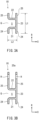
- FIG. 3A is a sectional view taken along line IIA-IIA of FIG. 2 .
- FIG. 3B is a sectional view taken along line IIB-IIB of FIG. 2 .
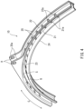
- FIG. 4 is a partial perspective view of the unison ring 10 shown in FIG. 2 .
- the unison ring 10 is an annular body made of fiber-reinforced resin by integral molding.
- the unison ring 10 may include separate circular-arc bodies located circumferentially and have a practically annular shape as a whole.
- An axis X of the unison ring 10 passes through a center of the unison ring 10 and is orthogonal to a radial direction R of the unison ring 10.
- a direction (hereinafter referred to as an "axial direction X") in which the axis X of the unison ring 10 extends is a direction orthogonal to the radial direction R of the unison ring 10.
- a circumferential direction C of the unison ring 10 is a direction along an outer peripheral surface of the unison ring 10. To be specific, when viewed in the axial direction X, the circumferential direction C of the unison ring 10 is a direction along a circle whose center is the axis X of the unison ring 10.
- the unison ring 10 may adopt various sectional shapes.
- the unison ring 10 includes an inner plate 21, an outer plate 22, a coupling plate 23, a pair of inner flange plates 24, and a pair of outer flange plates 25.
- Each of the inner plate 21 and the outer plate 22 has a cylindrical shape including main surfaces facing the radial direction R.
- the outer plate 22 is located concentrically with the inner plate 21 and away from the inner plate 21 outward in the radial direction R.
- the inner plate 21 includes pin holes 21a located at intervals in the circumferential direction
- the outer plate 22 includes pin holes 22a located at intervals in the circumferential direction.
- the pin holes 21a of the inner plate 21 and the pin holes 22a of the outer plate 22 coincide with each other when viewed in the radial direction R.
- the coupling plate 23 has an annular flat plate shape including main surfaces facing the axial direction X.
- the coupling plate 23 couples one end of the inner plate 21 in the axial direction X to one end of the outer plate 22 in the axial direction X.
- An intermediate space S between the inner plate 21 and the outer plate 22 is open toward a side in the axial direction X which is opposite to a side at which the coupling plate 23 is.
- the unison ring 10 includes an opening Q between the other end of the inner plate 21 in the axial direction X and the other end of the outer plate 22 in the axial direction X.
- Each of the pair of inner flange plates 24 has an annular flat plate shape including main surfaces facing the axial direction X.
- the pair of inner flange plates 24 are located away from each other in the axial direction X.
- the pair of inner flange plates 24 project inward in the radial direction R from both ends of the inner plate 21 in the axial direction X, respectively.
- Each of the pair of outer flange plates 25 has an annular flat plate shape including main surfaces facing the axial direction X.
- the pair of outer flange plates 25 are located away from each other in the axial direction X.
- the pair of outer flange plates 25 project outward in the radial direction R from both ends of the outer plate 22 in the axial direction X, respectively.
- Each of the pair of outer flange plates 25 includes a support 25a partially projecting in the radial direction R.
- the support 25a is integrally molded as a part of the outer flange plate 25.
- the support 25a includes a support hole H penetrating in the axial direction X.
- the support 25a is a portion to which driving power of a below-described actuator 18 is input to angularly displace the unison ring 10 relative to the casing 2 around the axis X.
- the section of the unison ring 10 orthogonal to the circumferential direction C has a ⁇ shape when the axial direction X is set to an upper-lower direction.
- the section of the unison ring 10 orthogonal to the circumferential direction C has such a shape that a dimension L1 of the unison ring 10 in the radial direction R is larger than a dimension L2 of the unison ring 10 in the axial direction X regardless of the position of the section in the circumferential direction C.
- "L1 > L2" is satisfied in not only the section shown in FIG. 3B but also the section shown in FIG. 3A .
- the unison ring 10 is made of fiber-reinforced resin containing resin and reinforced fibers.
- the resin is a resin material selected from bismaleimide, epoxy, polyimide, and the like.
- the reinforced fibers are fibrous materials selected from carbon fibers, glass fibers, aramid fibers, and the like.
- the unison ring 10 is manufactured by laminating prepregs and subjecting the prepregs to pressing. The prepregs are prepared by impregnating reinforced fiber sheets with the resin.
- the reinforced fiber sheets include, for example, a sheet made of a UD material in which reinforced fibers are oriented in one direction and a sheet made of a fabric material in which reinforced fibers are oriented in two directions.
- the orientation of the UD material extends in the circumferential direction C of the unison ring 10.
- One of the orientations of the fabric material extends in the circumferential direction C of the unison ring 10.
- a ratio of the reinforced fibers extending in the circumferential direction C of the unison ring 10 to all the reinforced fibers of the fabric material may be 50% or more.
- the most common orientations among all the orientations of the reinforced fibers in the entire unison ring 10 extend in the circumferential direction C of the unison ring 10.
- a main orientation of the reinforced fibers of the fiber-reinforced resin is directed in the circumferential direction C of the unison ring 10.
- the reinforced fiber sheets include first reinforced fiber sheets, second reinforced fiber sheet, and third reinforced fiber sheets. Two sheets among the first to third reinforced fiber sheets are partially laminated on each other. In the section of the unison ring 10 orthogonal to the circumferential direction C, the first to third reinforced fiber sheets are located so as to partially extend in different directions.
- a reinforced fiber filler impregnated with the resin is in the gap. Therefore, the decrease in strength due to the gap is prevented.
- a reinforced fiber sheet rounded in a tubular shape may be used as the reinforced fiber filler. It is preferable that the main orientation of the reinforced fibers of the reinforced fiber filler be directed in the circumferential direction C of the unison ring 10.
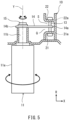
- FIG. 5 is a sectional view showing major components of the gas turbine engine 1 to which the unison ring 10 shown in FIG. 2 is applied.
- a pin 13 is in the pin holes 21a and 22a of the inner and outer plates 21 and 22 of the unison ring 10 in the radial direction R in a state where the pin 13 is prevented from coming out.
- the pin 13 is in a first end portion 14a of a lever 14 so as to be rotatable.
- the first end portion 14a of the lever 14 is in connection with the pin 13 in the intermediate space S of the unison ring 10 so as to be rotatable and extends through the opening Q of the unison ring 10 in the axial direction X to an outside of the intermediate space S.
- the variable stator vane 11 includes a stator vane main body 11a and a shaft 11b.
- the stator vane main body 11a is a blade that contacts and rectifies a fluid in the compressor 3.
- the shaft 11b projects from the stator vane main body 11a outward in the radial direction R to an outside of the casing 2.
- a second end portion 14b of the lever 14 is fixed to the shaft 11b of the variable stator vane 11 by a fastener 15 so as not to be rotatable.
- a rotation axis Y of the variable stator vane 11 is an axis of the shaft 11b.
- FIG. 6 is a diagram for explaining an operation trajectory T of the pin hole 22a of the unison ring 10 when the unison ring 10 and the like shown in FIG. 5 are viewed from an outside in the radial direction R.
- both end portions of a pin 16 are in the support holes H (also see FIG. 2 ) of the pair of outer flange plates 25 in a state where the pin 16 is prevented from coming out.
- the pin 16 is in a tip portion of a rod 17 so as to be rotatable.
- the rod 17 is driven by the actuator 18 so as to advance or retreat in the circumferential direction C along the outer peripheral surface of the unison ring 10.
- FIG. 2 shows that the actuator 18 is in direct connection with the rod 17.
- a crank structure (not shown) and the like may be located between the actuator 18 and the rod 17.
- the unison ring 10 When the rod 17 advances or retreats by the driving power of the actuator 18, the unison ring 10 is angularly displaced in the circumferential direction C around the axis X. With this, the pin 13 moves in the circumferential direction C, the lever 14 turns around the axis Y, and the variable stator vane 11 is angularly displaced around the axis Y At this time, the driving power of the actuator 18 is input to the supports 25a of the unison ring 10. Thus, a load is input to a part of the unison ring 10 in the circumferential direction C ( FIG. 2 shows two load input portions (supports 25a)). Therefore, stress that causes bending deformation in the radial direction R is generated in the unison ring 10.
- the lever 14 since the lever 14 has a fixed length, the pin 13 and the pin hole 22a move on the trajectory T having a circular-arc shape about the axis Y of the variable stator vane 11. Therefore, in accordance with the advancing or retreating of the rod 17, the unison ring 10 moves in the circumferential direction C and also moves slightly in the axial direction X. In this case, an advance-retreat direction of the rod 17 slightly deviates from the circumferential direction C of the unison ring 10. Therefore, stress that causes torsional deformation around the circumferential direction C is generated in the unison ring 10.
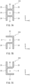
- FIG. 7A is a sectional view of a unison ring 110 of Modified Example 1.
- FIG. 7B is a sectional view of a unison ring 210 of Modified Example 2.
- FIG. 7C is a sectional view of a unison ring 310 of Modified Example 3.
- the same reference signs are used for components common to the components of the unison ring 10, and the repetition of the same explanation is avoided.
- the unison ring 110 of Modified Example 1 does not include the opening Q that opens the intermediate space S between the inner plate 21 and the outer plate 22.
- one of the pair of coupling plates 23 couples one end of the inner plate 21 in the axial direction X to one end of the outer plate 22 in the axial direction X
- the other of the pair of coupling plates 23 couples the other end of the inner plate 21 in the axial direction X to the other end of the outer plate 22 in the axial direction X. Since the other components are the same as those of the unison ring 10, explanations thereof are omitted.
- the unison ring 210 of Modified Example 2 does not include the outer flange plates 25. It is preferable that a dimension of the unison ring 210 in the radial direction R be larger than a dimension of the unison ring 210 in the axial direction X. Since the other components are the same as those of the unison ring 10, explanations thereof are omitted.
- the unison ring 310 of Modified Example 3 does not include the inner flange plates 24. It is preferable that a dimension of the unison ring 310 in the radial direction R be larger than a dimension of the unison ring 310 in the axial direction X. Since the other components are the same as those of the unison ring 10, explanations thereof are omitted.
- FIG. 8 is a graph showing the bending rigidity values of the unison rings having the respective sectional shapes.
- FIG. 9 is a graph showing the torsional rigidity values of the unison rings having the respective sectional shapes.
- the sectional shape of "Base” is a rectangular shape that is the sectional shape of a conventional unison ring.
- the sectional shape of "Case 1" is an annular shape.
- the sectional shape of "Case 2" is an I shape.
- the sectional shape of "Case 3" is a horseshoe shape.
- the sectional shape of "Case 4" is the sectional shape shown in FIG. 7A .
- the sectional shape of "Case 5" is the sectional shape shown in FIG. 3A .
- the sectional shape of "Case 6" is the sectional shape shown in FIG. 7B .
- the sectional shape of "Case 7" is the sectional shape of FIG. 7C .
- Each of vertical axes of the graphs of FIGS. 8 and 9 denotes a relative value based on a value of the sectional shape of Base.
- the unison ring 10 includes the fiber-reinforced resin, and the main orientation of the reinforced fibers is directed in the circumferential direction C of the unison ring 10. Therefore, the bending rigidity of the unison ring 10 can be improved while reducing the weight of the unison ring 10. On this account, the error of the angle of the variable stator vane 11 can be reduced, and the deteriorations of the operation stability and efficiency of the compressor 3 of the gas turbine engine 1 can be prevented.
- the section of the unison ring 10 orthogonal to the circumferential direction C has such a shape that the dimension L1 of the unison ring 10 in the radial direction R is larger than the dimension L2 of the unison ring 10 in the axial direction X. Therefore, the bending rigidity of the unison ring 10 in the radial direction R can be further improved.
- the torsional rigidity can be improved by the flange plate portions 24 and 25 while reducing the weight and improving the bending rigidity by the coupling plate 23.
- the intermediate space S between the inner plate 21 and the outer plate 22 is open toward a side in the axial direction X which is opposite to a side at which the coupling plate 23 is. Therefore, the lever 14 coupled to the variable stator vane 11 can be connected to the pin 13 in the intermediate space S between the inner plate 21 and the outer plate 22.
- the degree of freedom of the layout can be improved.
- the resin used in the unison ring 10 is selected from bismaleimide, epoxy, polyimide, and the like, and the reinforced fibers used in the unison ring 10 are selected from carbon fibers, glass fibers, aramid fibers, and the like. Therefore, the unison ring 10 having high specific strength and high heat resistance can be realized.
- the present disclosure is not limited to the above embodiment. Modifications, additions, and eliminations may be made with respect to the configuration of the embodiment.
- the sectional shape of the unison ring may be any shape as long as the unison ring is made of the fiber-reinforced resin, and the main orientation of the reinforced fibers is directed in the circumferential direction of the unison ring.
- the sectional shape of the unison ring may be any of the shapes shown in FIGS. 8 and 9 .
- the unison ring does not have to include the inner flange plates 24 and the outer flange plates 25.
- the lever 14 When the unison ring does not include the inner flange plates 24 and the outer flange plates 25, the lever 14 may be in connection with the pin 13 at an outside of the outer plate 22 in the radial direction R, or the lever 14 may be in connection with the pin 13 at an inside of the inner plate 21 in the radial direction R.
- the section of the unison ring 10 orthogonal to the circumferential direction C may have such a shape that the dimension of the unison ring 10 in the radial direction R is smaller than the dimension of the unison ring 10 in the axial direction X.
Landscapes
- Engineering & Computer Science (AREA)
- Chemical & Material Sciences (AREA)
- Combustion & Propulsion (AREA)
- Mechanical Engineering (AREA)
- General Engineering & Computer Science (AREA)
- Physics & Mathematics (AREA)
- Geometry (AREA)
- Fluid Mechanics (AREA)
- Structures Of Non-Positive Displacement Pumps (AREA)
Abstract
Description
- The present disclosure relates to a unison ring which is located along an outer periphery of a casing of a gas turbine engine including a compressor, a combustor, and a turbine and is coupled to variable stator vanes of the compressor.
- A gas turbine engine includes a compressor, a combustor, and a turbine which are lined up along a rotating shaft in a casing (see
PTL 1, for example). The compressor includes: moving vanes connected to the rotating shaft; and variable stator vanes connected to the casing. A rotating shaft portion of the variable stator vane projects outside the casing. A unison ring is located at an outer periphery side of the casing. A pin in a pin hole of the unison ring is coupled to the rotating shaft portion of the variable stator vane through a lever. When the unison ring is rotated by an actuator along an outer peripheral surface of the casing by a desired angle, this rotation is transmitted through the lever to the rotating shaft portion of the variable stator vane, and this changes an angle of the variable stator vane. - PTL 1:
Japanese Laid-Open Patent Application Publication No. 2014-47783 - When rotating the unison ring by the actuator, pressure received by the variable stator vane from compressed air in the compressor is applied as reaction force to the unison ring through the lever. Therefore, bending stress and torsional stress are generated in the unison ring, and this may deform the unison ring. When the unison ring is deformed, the angle of the variable stator vane deviates from a target angle. When there is an error in the angle of the variable stator vane, the operation of the compressor becomes unstable, and the deterioration of the efficiency of the compressor may occur.
- An object of the present disclosure is to devise a unison ring to prevent deteriorations of operation stability and efficiency of a compressor of a gas turbine engine.
- A unison ring of a gas turbine engine according to one aspect of the present disclosure is a unison ring of a gas turbine engine including a compressor, a combustor, and a turbine. The unison ring is located along an outer periphery of a casing of the gas turbine engine and coupled to variable stator vanes of the compressor. The unison ring includes: an annular body including fiber-reinforced resin or circular-arc bodies including the fiber-reinforced resin, the fiber-reinforced resin including resin and reinforced fibers; and pin holes in which a pin is in a radial direction orthogonal to an axial direction of the unison ring. A main orientation of the reinforced fibers of the fiber-reinforced resin is directed in a circumferential direction of the unison ring.
- According to the above configuration, the unison ring includes the fiber-reinforced resin, and the main orientation of the reinforced fibers is directed in the circumferential direction of the unison ring. Therefore, the bending rigidity of the unison ring can be improved while reducing the weight of the unison ring. On this account, the error of the angle of the variable stator vane can be reduced, and the deteriorations of the operation stability and efficiency of the compressor of the gas turbine engine can be prevented.
- The present disclosure can improve the rigidity of the unison ring and prevent the deteriorations of the operation stability and efficiency of the compressor of the gas turbine engine.
-
-
FIG. 1 is a schematic diagram showing a gas turbine according to an embodiment. -
FIG. 2 is a front view of a unison ring of the gas turbine engine shown inFIG. 1 . -
FIG. 3A is a sectional view taken along line IIA-IIA ofFIG. 2 .FIG. 3B is a sectional view taken along line IIB-IIB ofFIG. 2 . -
FIG. 4 is a partial perspective view of the unison ring shown inFIG. 2 . -
FIG. 5 is a sectional view of major components of the gas turbine engine to which the unison ring shown inFIG. 2 is applied. -
FIG. 6 is a diagram for explaining an operation trajectory of a pin hole of the unison ring when the unison ring and the like shown inFIG. 5 are viewed from an outside in a radial direction. -
FIG. 7A is a sectional view of the unison ring of Modified Example 1.FIG. 7B is a sectional view of the unison ring of Modified Example 2.FIG. 7C is a sectional view of the unison ring of Modified Example 3. -
FIG. 8 is a graph showing bending rigidity values of the unison rings having respective sectional shapes. -
FIG. 9 is a graph showing torsional rigidity values of the unison rings having the respective sectional shapes. - Hereinafter, an embodiment will be described with reference to the drawings.
-
FIG. 1 is a schematic diagram showing a gas turbine according to the embodiment. As shown inFIG. 1 , agas turbine engine 1 includes acasing 2. Thecasing 2 houses acompressor 3, acombustor 4, and aturbine 5. Thecompressor 3 and theturbine 5 are coupled to each other through a rotatingshaft 6. Thecompressor 3 rotates in association with theturbine 5 to compress air and supplies the compressed air to thecombustor 4. A combustion gas ejected from thecombustor 4 rotates theturbine 5 and is discharged to an outside. Thegas turbine engine 1 may be utilized as an aircraft engine. - The
compressor 3 includes plural pairs of moving vane rows and stator vane rows. At least one of the stator vane rows of thecompressor 3 includes variable stator vanes 11 (seeFIG. 5 ) lined up in a circumferential direction of thecasing 2 such that angles of attack of thevariable stator vanes 11 are adjustable.Unison rings 10 are externally fitted to thecasing 2 so as to be lined up in an axial direction of thegas turbine engine 1. Theunison rings 10 are rotatable relative to an outer peripheral surface of thecasing 2 in the circumferential direction. When theunison rings 10 are angularly displaced in the the circumferential direction (rotational direction) along the outer peripheral surface of thecasing 2, the angles of attack of the variable stator vanes 11 change. -
FIG. 2 is a front view of theunison ring 10 of thegas turbine engine 1 shown inFIG. 1 .FIG. 3A is a sectional view taken along line IIA-IIA ofFIG. 2 .FIG. 3B is a sectional view taken along line IIB-IIB ofFIG. 2 .FIG. 4 is a partial perspective view of theunison ring 10 shown inFIG. 2 . As shown inFIGS. 2 to 4 , theunison ring 10 is an annular body made of fiber-reinforced resin by integral molding. Theunison ring 10 may include separate circular-arc bodies located circumferentially and have a practically annular shape as a whole. - An axis X of the
unison ring 10 passes through a center of theunison ring 10 and is orthogonal to a radial direction R of theunison ring 10. A direction (hereinafter referred to as an "axial direction X") in which the axis X of theunison ring 10 extends is a direction orthogonal to the radial direction R of theunison ring 10. A circumferential direction C of theunison ring 10 is a direction along an outer peripheral surface of theunison ring 10. To be specific, when viewed in the axial direction X, the circumferential direction C of theunison ring 10 is a direction along a circle whose center is the axis X of theunison ring 10. - Regarding a section (section including the axis X of the unison ring 10) of the
unison ring 10 orthogonal to the circumferential direction C, theunison ring 10 may adopt various sectional shapes. As one example, theunison ring 10 includes aninner plate 21, anouter plate 22, acoupling plate 23, a pair ofinner flange plates 24, and a pair ofouter flange plates 25. Each of theinner plate 21 and theouter plate 22 has a cylindrical shape including main surfaces facing the radial direction R. Theouter plate 22 is located concentrically with theinner plate 21 and away from theinner plate 21 outward in the radial direction R. Theinner plate 21 includespin holes 21a located at intervals in the circumferential direction, and theouter plate 22 includespin holes 22a located at intervals in the circumferential direction. The pin holes 21a of theinner plate 21 and the pin holes 22a of theouter plate 22 coincide with each other when viewed in the radial direction R. - The
coupling plate 23 has an annular flat plate shape including main surfaces facing the axial direction X. Thecoupling plate 23 couples one end of theinner plate 21 in the axial direction X to one end of theouter plate 22 in the axial direction X. An intermediate space S between theinner plate 21 and theouter plate 22 is open toward a side in the axial direction X which is opposite to a side at which thecoupling plate 23 is. In other words, theunison ring 10 includes an opening Q between the other end of theinner plate 21 in the axial direction X and the other end of theouter plate 22 in the axial direction X. - Each of the pair of
inner flange plates 24 has an annular flat plate shape including main surfaces facing the axial direction X. The pair ofinner flange plates 24 are located away from each other in the axial direction X. The pair ofinner flange plates 24 project inward in the radial direction R from both ends of theinner plate 21 in the axial direction X, respectively. Each of the pair ofouter flange plates 25 has an annular flat plate shape including main surfaces facing the axial direction X. The pair ofouter flange plates 25 are located away from each other in the axial direction X. The pair ofouter flange plates 25 project outward in the radial direction R from both ends of theouter plate 22 in the axial direction X, respectively. - Each of the pair of
outer flange plates 25 includes asupport 25a partially projecting in the radial direction R. Thesupport 25a is integrally molded as a part of theouter flange plate 25. Thesupport 25a includes a support hole H penetrating in the axial direction X. Thesupport 25a is a portion to which driving power of a below-describedactuator 18 is input to angularly displace theunison ring 10 relative to thecasing 2 around the axis X. - In the present embodiment, the section of the
unison ring 10 orthogonal to the circumferential direction C has a π shape when the axial direction X is set to an upper-lower direction. The section of theunison ring 10 orthogonal to the circumferential direction C has such a shape that a dimension L1 of theunison ring 10 in the radial direction R is larger than a dimension L2 of theunison ring 10 in the axial direction X regardless of the position of the section in the circumferential direction C. To be specific, "L1 > L2" is satisfied in not only the section shown inFIG. 3B but also the section shown inFIG. 3A . - As described above, the
unison ring 10 is made of fiber-reinforced resin containing resin and reinforced fibers. The resin is a resin material selected from bismaleimide, epoxy, polyimide, and the like. The reinforced fibers are fibrous materials selected from carbon fibers, glass fibers, aramid fibers, and the like. Theunison ring 10 is manufactured by laminating prepregs and subjecting the prepregs to pressing. The prepregs are prepared by impregnating reinforced fiber sheets with the resin. - The reinforced fiber sheets include, for example, a sheet made of a UD material in which reinforced fibers are oriented in one direction and a sheet made of a fabric material in which reinforced fibers are oriented in two directions. The orientation of the UD material extends in the circumferential direction C of the
unison ring 10. One of the orientations of the fabric material extends in the circumferential direction C of theunison ring 10. For example, a ratio of the reinforced fibers extending in the circumferential direction C of theunison ring 10 to all the reinforced fibers of the fabric material may be 50% or more. - The most common orientations among all the orientations of the reinforced fibers in the
entire unison ring 10 extend in the circumferential direction C of theunison ring 10. To be specific, a main orientation of the reinforced fibers of the fiber-reinforced resin is directed in the circumferential direction C of theunison ring 10. - The reinforced fiber sheets include first reinforced fiber sheets, second reinforced fiber sheet, and third reinforced fiber sheets. Two sheets among the first to third reinforced fiber sheets are partially laminated on each other. In the section of the
unison ring 10 orthogonal to the circumferential direction C, the first to third reinforced fiber sheets are located so as to partially extend in different directions. - Therefore, there is a gap surrounded by the first to third reinforced fiber sheets. A reinforced fiber filler impregnated with the resin is in the gap. Therefore, the decrease in strength due to the gap is prevented. For example, a reinforced fiber sheet rounded in a tubular shape may be used as the reinforced fiber filler. It is preferable that the main orientation of the reinforced fibers of the reinforced fiber filler be directed in the circumferential direction C of the
unison ring 10. -
FIG. 5 is a sectional view showing major components of thegas turbine engine 1 to which theunison ring 10 shown inFIG. 2 is applied. As shown inFIG. 5 , apin 13 is in the pin holes 21a and 22a of the inner andouter plates unison ring 10 in the radial direction R in a state where thepin 13 is prevented from coming out. Thepin 13 is in afirst end portion 14a of alever 14 so as to be rotatable. Thefirst end portion 14a of thelever 14 is in connection with thepin 13 in the intermediate space S of theunison ring 10 so as to be rotatable and extends through the opening Q of theunison ring 10 in the axial direction X to an outside of the intermediate space S. - The
variable stator vane 11 includes a stator vanemain body 11a and ashaft 11b. The stator vanemain body 11a is a blade that contacts and rectifies a fluid in thecompressor 3. Theshaft 11b projects from the stator vanemain body 11a outward in the radial direction R to an outside of thecasing 2. Asecond end portion 14b of thelever 14 is fixed to theshaft 11b of thevariable stator vane 11 by afastener 15 so as not to be rotatable. A rotation axis Y of thevariable stator vane 11 is an axis of theshaft 11b. When thefirst end portion 14a of thelever 14 is displaced in the circumferential direction C, thesecond end portion 14b of thelever 14 angularly displaces thevariable stator vane 11 around the axis Y -
FIG. 6 is a diagram for explaining an operation trajectory T of thepin hole 22a of theunison ring 10 when theunison ring 10 and the like shown inFIG. 5 are viewed from an outside in the radial direction R. As shown inFIG. 6 , both end portions of apin 16 are in the support holes H (also seeFIG. 2 ) of the pair ofouter flange plates 25 in a state where thepin 16 is prevented from coming out. Thepin 16 is in a tip portion of arod 17 so as to be rotatable.
Therod 17 is driven by theactuator 18 so as to advance or retreat in the circumferential direction C along the outer peripheral surface of theunison ring 10. For simplicity,FIG. 2 shows that theactuator 18 is in direct connection with therod 17. However, as inPTL 1, a crank structure (not shown) and the like may be located between the actuator 18 and therod 17. - When the
rod 17 advances or retreats by the driving power of theactuator 18, theunison ring 10 is angularly displaced in the circumferential direction C around the axis X. With this, thepin 13 moves in the circumferential direction C, thelever 14 turns around the axis Y, and thevariable stator vane 11 is angularly displaced around the axis Y At this time, the driving power of theactuator 18 is input to thesupports 25a of theunison ring 10. Thus, a load is input to a part of theunison ring 10 in the circumferential direction C (FIG. 2 shows two load input portions (supports 25a)). Therefore, stress that causes bending deformation in the radial direction R is generated in theunison ring 10. - Moreover, since the
lever 14 has a fixed length, thepin 13 and thepin hole 22a move on the trajectory T having a circular-arc shape about the axis Y of thevariable stator vane 11. Therefore, in accordance with the advancing or retreating of therod 17, theunison ring 10 moves in the circumferential direction C and also moves slightly in the axial direction X. In this case, an advance-retreat direction of therod 17 slightly deviates from the circumferential direction C of theunison ring 10. Therefore, stress that causes torsional deformation around the circumferential direction C is generated in theunison ring 10. - The sectional shape of the
unison ring 10 is not limited to the above, and various sectional shapes may be adopted.FIG. 7A is a sectional view of aunison ring 110 of Modified Example 1.FIG. 7B is a sectional view of aunison ring 210 of Modified Example 2.FIG. 7C is a sectional view of aunison ring 310 of Modified Example 3. The same reference signs are used for components common to the components of theunison ring 10, and the repetition of the same explanation is avoided. - As shown in
FIG. 7A , unlike theunison ring 10 shown inFIG. 3A , theunison ring 110 of Modified Example 1 does not include the opening Q that opens the intermediate space S between theinner plate 21 and theouter plate 22. To be specific, in theunison ring 110, one of the pair ofcoupling plates 23 couples one end of theinner plate 21 in the axial direction X to one end of theouter plate 22 in the axial direction X, and the other of the pair ofcoupling plates 23 couples the other end of theinner plate 21 in the axial direction X to the other end of theouter plate 22 in the axial direction X. Since the other components are the same as those of theunison ring 10, explanations thereof are omitted. - As shown in
FIG. 7B , theunison ring 210 of Modified Example 2 does not include theouter flange plates 25. It is preferable that a dimension of theunison ring 210 in the radial direction R be larger than a dimension of theunison ring 210 in the axial direction X. Since the other components are the same as those of theunison ring 10, explanations thereof are omitted. - As shown in
FIG. 7C , theunison ring 310 of Modified Example 3 does not include theinner flange plates 24. It is preferable that a dimension of theunison ring 310 in the radial direction R be larger than a dimension of theunison ring 310 in the axial direction X. Since the other components are the same as those of theunison ring 10, explanations thereof are omitted. - Next, differences of bending rigidity and torsional rigidity between the unison rings having different sectional shapes will be discussed. Calculation results of bending rigidity values and torsional rigidity values of the unison rings having different sectional shapes were obtained by using computer simulation. In the present simulation, "Inspire" that is software produced by Altair Engineering was used. In the present simulation, conditions other than the sectional shape are set to be the same among the unison rings.
-
FIG. 8 is a graph showing the bending rigidity values of the unison rings having the respective sectional shapes.FIG. 9 is a graph showing the torsional rigidity values of the unison rings having the respective sectional shapes. The sectional shape of "Base" is a rectangular shape that is the sectional shape of a conventional unison ring. The sectional shape of "Case 1" is an annular shape. The sectional shape of "Case 2" is an I shape. The sectional shape of "Case 3" is a horseshoe shape. The sectional shape of "Case 4" is the sectional shape shown inFIG. 7A . The sectional shape of "Case 5" is the sectional shape shown inFIG. 3A . The sectional shape of "Case 6" is the sectional shape shown inFIG. 7B . The sectional shape of "Case 7" is the sectional shape ofFIG. 7C . Each of vertical axes of the graphs ofFIGS. 8 and 9 denotes a relative value based on a value of the sectional shape of Base. - It is clear from
FIG. 8 that the bending rigidity of the unison ring in each ofCases 2 to 7 is superior to the bending rigidity of the unison ring in each of Base andCase 1. Moreover, it is clear fromFIG. 9 that the torsional rigidity of the unison ring in each of Base andCases 4 to 7 is superior to the torsional rigidity of the unison ring in each ofCases Cases 4 to 7 are superior. - According to the above configuration, the
unison ring 10 includes the fiber-reinforced resin, and the main orientation of the reinforced fibers is directed in the circumferential direction C of theunison ring 10. Therefore, the bending rigidity of theunison ring 10 can be improved while reducing the weight of theunison ring 10. On this account, the error of the angle of thevariable stator vane 11 can be reduced, and the deteriorations of the operation stability and efficiency of thecompressor 3 of thegas turbine engine 1 can be prevented. - Moreover, the section of the
unison ring 10 orthogonal to the circumferential direction C has such a shape that the dimension L1 of theunison ring 10 in the radial direction R is larger than the dimension L2 of theunison ring 10 in the axial direction X. Therefore, the bending rigidity of theunison ring 10 in the radial direction R can be further improved. - Moreover, the torsional rigidity can be improved by the
flange plate portions coupling plate 23. Furthermore, the intermediate space S between theinner plate 21 and theouter plate 22 is open toward a side in the axial direction X which is opposite to a side at which thecoupling plate 23 is. Therefore, thelever 14 coupled to thevariable stator vane 11 can be connected to thepin 13 in the intermediate space S between theinner plate 21 and theouter plate 22. Thus, the degree of freedom of the layout can be improved. - Moreover, the resin used in the
unison ring 10 is selected from bismaleimide, epoxy, polyimide, and the like, and the reinforced fibers used in theunison ring 10 are selected from carbon fibers, glass fibers, aramid fibers, and the like. Therefore, theunison ring 10 having high specific strength and high heat resistance can be realized. - The present disclosure is not limited to the above embodiment. Modifications, additions, and eliminations may be made with respect to the configuration of the embodiment. The sectional shape of the unison ring may be any shape as long as the unison ring is made of the fiber-reinforced resin, and the main orientation of the reinforced fibers is directed in the circumferential direction of the unison ring. For example, the sectional shape of the unison ring may be any of the shapes shown in
FIGS. 8 and 9 . The unison ring does not have to include theinner flange plates 24 and theouter flange plates 25. When the unison ring does not include theinner flange plates 24 and theouter flange plates 25, thelever 14 may be in connection with thepin 13 at an outside of theouter plate 22 in the radial direction R, or thelever 14 may be in connection with thepin 13 at an inside of theinner plate 21 in the radial direction R. The section of theunison ring 10 orthogonal to the circumferential direction C may have such a shape that the dimension of theunison ring 10 in the radial direction R is smaller than the dimension of theunison ring 10 in the axial direction X. -
- 1
- gas turbine engine
- 2
- casing
- 3
- compressor
- 4
- combustor
- 5
- turbine
- 10, 110, 210, 310
- unison ring
- 11
- variable stator vane
- 21
- inner plate
- 21a
- pin hole
- 22
- outer plate
- 22a
- pin hole
- 23
- coupling plate
- 24
- inner flange plate
- 25
- outer flange plate
- C
- circumferential direction
- G
- gap
- Q
- opening
- R
- radial direction
- S
- intermediate space
- T
- trajectory
- X
- axial direction
- Y
- axis
Claims (7)
- A unison ring of a gas turbine engine including a compressor, a combustor, and a turbine,the unison ring being located along an outer periphery of a casing of the gas turbine engine and coupled to variable stator vanes of the compressor,the unison ring comprising:an annular body including fiber-reinforced resin or circular-arc bodies including the fiber-reinforced resin, the fiber-reinforced resin including resin and reinforced fibers; andpin holes in which a pin is in a radial direction orthogonal to an axial direction of the unison ring, whereina main orientation of the reinforced fibers of the fiber-reinforced resin is directed in a circumferential direction of the unison ring.
- The unison ring according to claim 1, wherein a section of the unison ring orthogonal to the circumferential direction has such a shape that a dimension of the unison ring in the radial direction is larger than a dimension of the unison ring in the axial direction.
- The unison ring according to claim 1 or 2, comprising:an inner plate including the pin hole and main surfaces facing the radial direction;an outer plate including the pin hole and main surfaces facing the radial direction, the inner plate and the outer plate being located concentrically;a coupling plate including main surfaces facing the axial direction, the coupling plate coupling the inner plate to the outer plate; andat least one flange plate portion including main surfaces facing the axial direction, the at least one flange plate projecting in the radial direction from at least one of an end of the inner plate in the axial direction or an end of the outer plate in the axial direction.
- The unison ring according to claim 3, wherein the at least one flange plate portion comprises:a pair of inner flange plates projecting inward in the radial direction from both ends of the inner plate in the axial direction; anda pair of outer flange plates projecting outward in the radial direction from both ends of the outer plate in the axial direction.
- The unison ring according to claim 3 or 4, wherein:the coupling plate couples one end of the inner plate in the axial direction to one end of the outer plate in the axial direction; anda space between the inner plate and the outer plate is open toward a side in the axial direction which is opposite to a side at which the coupling plate is.
- The unison ring according to any one of claims 1 to 5, wherein a section of the unison ring orthogonal to the circumferential direction has a π shape when the axial direction is set to an upper-lower direction.
- The unison ring according to any one of claims 1 to 6, wherein:the resin is selected from bismaleimide, epoxy, and polyimide; andthe reinforced fibers are selected from carbon fibers, glass fibers, and aramid fibers.
Applications Claiming Priority (2)
| Application Number | Priority Date | Filing Date | Title |
|---|---|---|---|
| JP2020061796A JP7431640B2 (en) | 2020-03-31 | 2020-03-31 | gas turbine engine unison ring |
| PCT/JP2021/009626 WO2021199995A1 (en) | 2020-03-31 | 2021-03-10 | Unison ring for gas turbine engine |
Publications (3)
| Publication Number | Publication Date |
|---|---|
| EP4130491A1 true EP4130491A1 (en) | 2023-02-08 |
| EP4130491A4 EP4130491A4 (en) | 2024-04-03 |
| EP4130491B1 EP4130491B1 (en) | 2025-01-22 |
Family
ID=77928674
Family Applications (1)
| Application Number | Title | Priority Date | Filing Date |
|---|---|---|---|
| EP21782424.2A Active EP4130491B1 (en) | 2020-03-31 | 2021-03-10 | Unison ring for gas turbine engine |
Country Status (4)
| Country | Link |
|---|---|
| US (1) | US11840959B2 (en) |
| EP (1) | EP4130491B1 (en) |
| JP (1) | JP7431640B2 (en) |
| WO (1) | WO2021199995A1 (en) |
Families Citing this family (1)
| Publication number | Priority date | Publication date | Assignee | Title |
|---|---|---|---|---|
| DE102021128979A1 (en) * | 2021-11-08 | 2023-05-11 | MTU Aero Engines AG | ADJUSTING LEVER FOR A HYDRAULIC MACHINE |
Family Cites Families (16)
| Publication number | Priority date | Publication date | Assignee | Title |
|---|---|---|---|---|
| US4307994A (en) * | 1979-10-15 | 1981-12-29 | General Motors Corporation | Variable vane position adjuster |
| DE19516382A1 (en) * | 1995-05-04 | 1996-11-07 | Deutsche Forsch Luft Raumfahrt | Adjustment ring |
| JP4211087B2 (en) * | 1998-05-27 | 2009-01-21 | 株式会社Ihi | Movable vane drive mechanism |
| US6984104B2 (en) * | 2002-12-16 | 2006-01-10 | United Technologies Corporation | Variable vane arm/unison ring attachment system |
| DE10352099B4 (en) * | 2003-11-08 | 2017-08-24 | MTU Aero Engines AG | Device for adjusting vanes |
| US7543992B2 (en) * | 2005-04-28 | 2009-06-09 | General Electric Company | High temperature rod end bearings |
| FR2902454A1 (en) * | 2006-06-16 | 2007-12-21 | Snecma Sa | TURBOMACHINE STATOR COMPRISING A FLOOR OF ADJUSTERS ADJUSTED BY A ROTATING CROWN WITH AUTOMATIC CENTERING |
| US7914256B2 (en) | 2007-04-17 | 2011-03-29 | General Electric Company | Articles made from composite materials having toughened and untoughened regions |
| FR2921100B1 (en) * | 2007-09-13 | 2009-12-04 | Snecma | ROTATIONAL DRIVE LEVER AROUND A VARIABLE TURBOMACHINE STATOR VANE PIVOT |
| CN102131847A (en) * | 2008-08-29 | 2011-07-20 | 纳幕尔杜邦公司 | Composite parts for airplane engines |
| US8262345B2 (en) * | 2009-02-06 | 2012-09-11 | General Electric Company | Ceramic matrix composite turbine engine |
| US8714916B2 (en) * | 2010-09-28 | 2014-05-06 | General Electric Company | Variable vane assembly for a turbine compressor |
| US20140064910A1 (en) | 2012-08-29 | 2014-03-06 | General Electric Company | Systems and Methods to Control Variable Stator Vanes in Gas Turbine Engines |
| US9822651B2 (en) * | 2012-09-28 | 2017-11-21 | United Technologies Corporation | Synchronization ring runner with cradle |
| JP5736443B1 (en) * | 2013-12-19 | 2015-06-17 | 川崎重工業株式会社 | Variable vane mechanism |
| DE102017124339B4 (en) * | 2017-10-18 | 2023-03-02 | Deutsches Zentrum für Luft- und Raumfahrt e.V. | Variable ring, compressor and method of operating a variable ring |
-
2020
- 2020-03-31 JP JP2020061796A patent/JP7431640B2/en active Active
-
2021
- 2021-03-10 US US17/916,287 patent/US11840959B2/en active Active
- 2021-03-10 EP EP21782424.2A patent/EP4130491B1/en active Active
- 2021-03-10 WO PCT/JP2021/009626 patent/WO2021199995A1/en not_active Ceased
Also Published As
| Publication number | Publication date |
|---|---|
| JP2021161885A (en) | 2021-10-11 |
| US11840959B2 (en) | 2023-12-12 |
| US20230147099A1 (en) | 2023-05-11 |
| WO2021199995A1 (en) | 2021-10-07 |
| EP4130491A4 (en) | 2024-04-03 |
| JP7431640B2 (en) | 2024-02-15 |
| EP4130491B1 (en) | 2025-01-22 |
Similar Documents
| Publication | Publication Date | Title |
|---|---|---|
| CN111075755B (en) | Platform equipment for propulsion of rotors | |
| EP2211026B1 (en) | A variable stator vane assembly in a gas turbine engine | |
| CN108457900B (en) | Fan with cooling device | |
| US6688846B2 (en) | Device for controlling variable-pitch blades | |
| US9903228B2 (en) | Composite casing for a compressor of an axial-flow turbomachine | |
| US6234756B1 (en) | Segmented ring blade retainer | |
| US10280758B2 (en) | Composite compressor blade for an axial-flow turbomachine | |
| US9121302B2 (en) | Radial compressor blade clearance control system | |
| US20150192140A1 (en) | Composite Housing with a Metallic Flange for the Compressor of an Axial Turbomachine | |
| US11773735B2 (en) | Vane ring assembly with ceramic matrix composite airfoils | |
| US10859268B2 (en) | Ceramic matrix composite turbine vanes and vane ring assemblies | |
| US11840959B2 (en) | Unison ring of gas turbine engine | |
| US12152633B2 (en) | Composite drive shafts | |
| CN105960521B (en) | The manufacture method of fan drum and fan drum | |
| EP2725192B1 (en) | Turbomachine blade reinforcement | |
| US11993365B2 (en) | Aircraft turbine engine comprising variable-pitch propeller blades | |
| US9951654B2 (en) | Stator blade sector for an axial turbomachine with a dual means of fixing | |
| US12372001B2 (en) | Secondary flow guide vane of a turbomachine and turbomachine provided therewith | |
| EP2895704B1 (en) | Gas turbine engine synchronizing ring with multi-axis joint | |
| US9896972B2 (en) | Faceted housing for axial turbomachine compressor | |
| US10590957B2 (en) | Turbine engine compressor, in particular for an aircraft turboprop engine or turbojet engine | |
| US20200300161A1 (en) | Position securement of an exhaust gas turbocharger housing | |
| US20040001754A1 (en) | Combined ball-and-damper device for a helicopter rotor | |
| EP3734017A1 (en) | Gas turbine engine with fan case having integrated stator vanes | |
| CN106574555A (en) | Cylindrical case |
Legal Events
| Date | Code | Title | Description |
|---|---|---|---|
| STAA | Information on the status of an ep patent application or granted ep patent |
Free format text: STATUS: THE INTERNATIONAL PUBLICATION HAS BEEN MADE |
|
| PUAI | Public reference made under article 153(3) epc to a published international application that has entered the european phase |
Free format text: ORIGINAL CODE: 0009012 |
|
| STAA | Information on the status of an ep patent application or granted ep patent |
Free format text: STATUS: REQUEST FOR EXAMINATION WAS MADE |
|
| 17P | Request for examination filed |
Effective date: 20221014 |
|
| AK | Designated contracting states |
Kind code of ref document: A1 Designated state(s): AL AT BE BG CH CY CZ DE DK EE ES FI FR GB GR HR HU IE IS IT LI LT LU LV MC MK MT NL NO PL PT RO RS SE SI SK SM TR |
|
| DAV | Request for validation of the european patent (deleted) | ||
| DAX | Request for extension of the european patent (deleted) | ||
| A4 | Supplementary search report drawn up and despatched |
Effective date: 20240229 |
|
| RIC1 | Information provided on ipc code assigned before grant |
Ipc: F01D 17/16 20060101ALI20240223BHEP Ipc: F02C 7/042 20060101ALI20240223BHEP Ipc: F04D 29/56 20060101AFI20240223BHEP |
|
| GRAP | Despatch of communication of intention to grant a patent |
Free format text: ORIGINAL CODE: EPIDOSNIGR1 |
|
| STAA | Information on the status of an ep patent application or granted ep patent |
Free format text: STATUS: GRANT OF PATENT IS INTENDED |
|
| INTG | Intention to grant announced |
Effective date: 20240925 |
|
| GRAS | Grant fee paid |
Free format text: ORIGINAL CODE: EPIDOSNIGR3 |
|
| GRAA | (expected) grant |
Free format text: ORIGINAL CODE: 0009210 |
|
| STAA | Information on the status of an ep patent application or granted ep patent |
Free format text: STATUS: THE PATENT HAS BEEN GRANTED |
|
| AK | Designated contracting states |
Kind code of ref document: B1 Designated state(s): AL AT BE BG CH CY CZ DE DK EE ES FI FR GB GR HR HU IE IS IT LI LT LU LV MC MK MT NL NO PL PT RO RS SE SI SK SM TR |
|
| REG | Reference to a national code |
Ref country code: GB Ref legal event code: FG4D |
|
| REG | Reference to a national code |
Ref country code: CH Ref legal event code: EP |
|
| REG | Reference to a national code |
Ref country code: IE Ref legal event code: FG4D |
|
| REG | Reference to a national code |
Ref country code: DE Ref legal event code: R096 Ref document number: 602021025163 Country of ref document: DE |
|
| PGFP | Annual fee paid to national office [announced via postgrant information from national office to epo] |
Ref country code: AT Payment date: 20250417 Year of fee payment: 5 |
|
| REG | Reference to a national code |
Ref country code: NL Ref legal event code: MP Effective date: 20250122 |
|
| PG25 | Lapsed in a contracting state [announced via postgrant information from national office to epo] |
Ref country code: NL Free format text: LAPSE BECAUSE OF FAILURE TO SUBMIT A TRANSLATION OF THE DESCRIPTION OR TO PAY THE FEE WITHIN THE PRESCRIBED TIME-LIMIT Effective date: 20250122 |
|
| PG25 | Lapsed in a contracting state [announced via postgrant information from national office to epo] |
Ref country code: RS Free format text: LAPSE BECAUSE OF FAILURE TO SUBMIT A TRANSLATION OF THE DESCRIPTION OR TO PAY THE FEE WITHIN THE PRESCRIBED TIME-LIMIT Effective date: 20250422 |
|
| PG25 | Lapsed in a contracting state [announced via postgrant information from national office to epo] |
Ref country code: FI Free format text: LAPSE BECAUSE OF FAILURE TO SUBMIT A TRANSLATION OF THE DESCRIPTION OR TO PAY THE FEE WITHIN THE PRESCRIBED TIME-LIMIT Effective date: 20250122 |
|
| PG25 | Lapsed in a contracting state [announced via postgrant information from national office to epo] |
Ref country code: PL Free format text: LAPSE BECAUSE OF FAILURE TO SUBMIT A TRANSLATION OF THE DESCRIPTION OR TO PAY THE FEE WITHIN THE PRESCRIBED TIME-LIMIT Effective date: 20250122 |
|
| PG25 | Lapsed in a contracting state [announced via postgrant information from national office to epo] |
Ref country code: ES Free format text: LAPSE BECAUSE OF FAILURE TO SUBMIT A TRANSLATION OF THE DESCRIPTION OR TO PAY THE FEE WITHIN THE PRESCRIBED TIME-LIMIT Effective date: 20250122 |
|
| REG | Reference to a national code |
Ref country code: LT Ref legal event code: MG9D |
|
| PG25 | Lapsed in a contracting state [announced via postgrant information from national office to epo] |
Ref country code: IS Free format text: LAPSE BECAUSE OF FAILURE TO SUBMIT A TRANSLATION OF THE DESCRIPTION OR TO PAY THE FEE WITHIN THE PRESCRIBED TIME-LIMIT Effective date: 20250522 Ref country code: NO Free format text: LAPSE BECAUSE OF FAILURE TO SUBMIT A TRANSLATION OF THE DESCRIPTION OR TO PAY THE FEE WITHIN THE PRESCRIBED TIME-LIMIT Effective date: 20250422 |
|
| REG | Reference to a national code |
Ref country code: AT Ref legal event code: MK05 Ref document number: 1761657 Country of ref document: AT Kind code of ref document: T Effective date: 20250122 |
|
| PG25 | Lapsed in a contracting state [announced via postgrant information from national office to epo] |
Ref country code: HR Free format text: LAPSE BECAUSE OF FAILURE TO SUBMIT A TRANSLATION OF THE DESCRIPTION OR TO PAY THE FEE WITHIN THE PRESCRIBED TIME-LIMIT Effective date: 20250122 |
|
| PG25 | Lapsed in a contracting state [announced via postgrant information from national office to epo] |
Ref country code: LV Free format text: LAPSE BECAUSE OF FAILURE TO SUBMIT A TRANSLATION OF THE DESCRIPTION OR TO PAY THE FEE WITHIN THE PRESCRIBED TIME-LIMIT Effective date: 20250122 Ref country code: PT Free format text: LAPSE BECAUSE OF FAILURE TO SUBMIT A TRANSLATION OF THE DESCRIPTION OR TO PAY THE FEE WITHIN THE PRESCRIBED TIME-LIMIT Effective date: 20250522 |
|
| PG25 | Lapsed in a contracting state [announced via postgrant information from national office to epo] |
Ref country code: BG Free format text: LAPSE BECAUSE OF FAILURE TO SUBMIT A TRANSLATION OF THE DESCRIPTION OR TO PAY THE FEE WITHIN THE PRESCRIBED TIME-LIMIT Effective date: 20250122 Ref country code: GR Free format text: LAPSE BECAUSE OF FAILURE TO SUBMIT A TRANSLATION OF THE DESCRIPTION OR TO PAY THE FEE WITHIN THE PRESCRIBED TIME-LIMIT Effective date: 20250423 |
|
| PG25 | Lapsed in a contracting state [announced via postgrant information from national office to epo] |
Ref country code: AT Free format text: LAPSE BECAUSE OF FAILURE TO SUBMIT A TRANSLATION OF THE DESCRIPTION OR TO PAY THE FEE WITHIN THE PRESCRIBED TIME-LIMIT Effective date: 20250122 |
|
| PG25 | Lapsed in a contracting state [announced via postgrant information from national office to epo] |
Ref country code: SE Free format text: LAPSE BECAUSE OF FAILURE TO SUBMIT A TRANSLATION OF THE DESCRIPTION OR TO PAY THE FEE WITHIN THE PRESCRIBED TIME-LIMIT Effective date: 20250122 |
|
| PG25 | Lapsed in a contracting state [announced via postgrant information from national office to epo] |
Ref country code: SM Free format text: LAPSE BECAUSE OF FAILURE TO SUBMIT A TRANSLATION OF THE DESCRIPTION OR TO PAY THE FEE WITHIN THE PRESCRIBED TIME-LIMIT Effective date: 20250122 |
|
| PG25 | Lapsed in a contracting state [announced via postgrant information from national office to epo] |
Ref country code: DK Free format text: LAPSE BECAUSE OF FAILURE TO SUBMIT A TRANSLATION OF THE DESCRIPTION OR TO PAY THE FEE WITHIN THE PRESCRIBED TIME-LIMIT Effective date: 20250122 |
|
| PG25 | Lapsed in a contracting state [announced via postgrant information from national office to epo] |
Ref country code: MC Free format text: LAPSE BECAUSE OF FAILURE TO SUBMIT A TRANSLATION OF THE DESCRIPTION OR TO PAY THE FEE WITHIN THE PRESCRIBED TIME-LIMIT Effective date: 20250122 |
|
| PG25 | Lapsed in a contracting state [announced via postgrant information from national office to epo] |
Ref country code: IT Free format text: LAPSE BECAUSE OF FAILURE TO SUBMIT A TRANSLATION OF THE DESCRIPTION OR TO PAY THE FEE WITHIN THE PRESCRIBED TIME-LIMIT Effective date: 20250122 |
|
| PG25 | Lapsed in a contracting state [announced via postgrant information from national office to epo] |
Ref country code: CZ Free format text: LAPSE BECAUSE OF FAILURE TO SUBMIT A TRANSLATION OF THE DESCRIPTION OR TO PAY THE FEE WITHIN THE PRESCRIBED TIME-LIMIT Effective date: 20250122 Ref country code: EE Free format text: LAPSE BECAUSE OF FAILURE TO SUBMIT A TRANSLATION OF THE DESCRIPTION OR TO PAY THE FEE WITHIN THE PRESCRIBED TIME-LIMIT Effective date: 20250122 |
|
| REG | Reference to a national code |
Ref country code: CH Ref legal event code: H13 Free format text: ST27 STATUS EVENT CODE: U-0-0-H10-H13 (AS PROVIDED BY THE NATIONAL OFFICE) Effective date: 20251023 Ref country code: DE Ref legal event code: R097 Ref document number: 602021025163 Country of ref document: DE |
|
| PG25 | Lapsed in a contracting state [announced via postgrant information from national office to epo] |
Ref country code: RO Free format text: LAPSE BECAUSE OF FAILURE TO SUBMIT A TRANSLATION OF THE DESCRIPTION OR TO PAY THE FEE WITHIN THE PRESCRIBED TIME-LIMIT Effective date: 20250122 |
|
| PG25 | Lapsed in a contracting state [announced via postgrant information from national office to epo] |
Ref country code: SK Free format text: LAPSE BECAUSE OF FAILURE TO SUBMIT A TRANSLATION OF THE DESCRIPTION OR TO PAY THE FEE WITHIN THE PRESCRIBED TIME-LIMIT Effective date: 20250122 |
|
| PG25 | Lapsed in a contracting state [announced via postgrant information from national office to epo] |
Ref country code: LU Free format text: LAPSE BECAUSE OF NON-PAYMENT OF DUE FEES Effective date: 20250310 |
|
| PLBE | No opposition filed within time limit |
Free format text: ORIGINAL CODE: 0009261 |
|
| STAA | Information on the status of an ep patent application or granted ep patent |
Free format text: STATUS: NO OPPOSITION FILED WITHIN TIME LIMIT |
|
| REG | Reference to a national code |
Ref country code: BE Ref legal event code: MM Effective date: 20250331 |
|
| 26N | No opposition filed |
Effective date: 20251023 |
|
| PG25 | Lapsed in a contracting state [announced via postgrant information from national office to epo] |
Ref country code: BE Free format text: LAPSE BECAUSE OF NON-PAYMENT OF DUE FEES Effective date: 20250331 |
|
| PG25 | Lapsed in a contracting state [announced via postgrant information from national office to epo] |
Ref country code: CH Free format text: LAPSE BECAUSE OF NON-PAYMENT OF DUE FEES Effective date: 20250331 |
|
| PG25 | Lapsed in a contracting state [announced via postgrant information from national office to epo] |
Ref country code: IE Free format text: LAPSE BECAUSE OF NON-PAYMENT OF DUE FEES Effective date: 20250310 |
|
| PGFP | Annual fee paid to national office [announced via postgrant information from national office to epo] |
Ref country code: GB Payment date: 20260218 Year of fee payment: 6 |
|
| PGFP | Annual fee paid to national office [announced via postgrant information from national office to epo] |
Ref country code: DE Payment date: 20260218 Year of fee payment: 6 |
|
| PGFP | Annual fee paid to national office [announced via postgrant information from national office to epo] |
Ref country code: FR Payment date: 20260218 Year of fee payment: 6 |
|
| PG25 | Lapsed in a contracting state [announced via postgrant information from national office to epo] |
Ref country code: CY Free format text: LAPSE BECAUSE OF FAILURE TO SUBMIT A TRANSLATION OF THE DESCRIPTION OR TO PAY THE FEE WITHIN THE PRESCRIBED TIME-LIMIT Effective date: 20250122 |
|
| PG25 | Lapsed in a contracting state [announced via postgrant information from national office to epo] |
Ref country code: LT Free format text: LAPSE BECAUSE OF FAILURE TO SUBMIT A TRANSLATION OF THE DESCRIPTION OR TO PAY THE FEE WITHIN THE PRESCRIBED TIME-LIMIT Effective date: 20250122 |
|
| PG25 | Lapsed in a contracting state [announced via postgrant information from national office to epo] |
Ref country code: TR Free format text: LAPSE BECAUSE OF FAILURE TO SUBMIT A TRANSLATION OF THE DESCRIPTION OR TO PAY THE FEE WITHIN THE PRESCRIBED TIME-LIMIT Effective date: 20250122 |