EP4130483A1 - Fan apparatus and air conditioner outdoor unit - Google Patents
Fan apparatus and air conditioner outdoor unit Download PDFInfo
- Publication number
- EP4130483A1 EP4130483A1 EP21876972.7A EP21876972A EP4130483A1 EP 4130483 A1 EP4130483 A1 EP 4130483A1 EP 21876972 A EP21876972 A EP 21876972A EP 4130483 A1 EP4130483 A1 EP 4130483A1
- Authority
- EP
- European Patent Office
- Prior art keywords
- wind wheel
- blades
- fan apparatus
- axial direction
- wind
- Prior art date
- Legal status (The legal status is an assumption and is not a legal conclusion. Google has not performed a legal analysis and makes no representation as to the accuracy of the status listed.)
- Granted
Links
Images






Classifications
-
- F—MECHANICAL ENGINEERING; LIGHTING; HEATING; WEAPONS; BLASTING
- F04—POSITIVE - DISPLACEMENT MACHINES FOR LIQUIDS; PUMPS FOR LIQUIDS OR ELASTIC FLUIDS
- F04D—NON-POSITIVE-DISPLACEMENT PUMPS
- F04D29/00—Details, component parts, or accessories
- F04D29/26—Rotors specially for elastic fluids
- F04D29/32—Rotors specially for elastic fluids for axial flow pumps
- F04D29/38—Blades
-
- F—MECHANICAL ENGINEERING; LIGHTING; HEATING; WEAPONS; BLASTING
- F04—POSITIVE - DISPLACEMENT MACHINES FOR LIQUIDS; PUMPS FOR LIQUIDS OR ELASTIC FLUIDS
- F04D—NON-POSITIVE-DISPLACEMENT PUMPS
- F04D25/00—Pumping installations or systems
- F04D25/02—Units comprising pumps and their driving means
- F04D25/08—Units comprising pumps and their driving means the working fluid being air, e.g. for ventilation
-
- F—MECHANICAL ENGINEERING; LIGHTING; HEATING; WEAPONS; BLASTING
- F04—POSITIVE - DISPLACEMENT MACHINES FOR LIQUIDS; PUMPS FOR LIQUIDS OR ELASTIC FLUIDS
- F04D—NON-POSITIVE-DISPLACEMENT PUMPS
- F04D25/00—Pumping installations or systems
- F04D25/16—Combinations of two or more pumps ; Producing two or more separate gas flows
- F04D25/166—Combinations of two or more pumps ; Producing two or more separate gas flows using fans
-
- F—MECHANICAL ENGINEERING; LIGHTING; HEATING; WEAPONS; BLASTING
- F04—POSITIVE - DISPLACEMENT MACHINES FOR LIQUIDS; PUMPS FOR LIQUIDS OR ELASTIC FLUIDS
- F04D—NON-POSITIVE-DISPLACEMENT PUMPS
- F04D29/00—Details, component parts, or accessories
- F04D29/40—Casings; Connections of working fluid
- F04D29/52—Casings; Connections of working fluid for axial pumps
- F04D29/54—Fluid-guiding means, e.g. diffusers
- F04D29/541—Specially adapted for elastic fluid pumps
-
- F—MECHANICAL ENGINEERING; LIGHTING; HEATING; WEAPONS; BLASTING
- F04—POSITIVE - DISPLACEMENT MACHINES FOR LIQUIDS; PUMPS FOR LIQUIDS OR ELASTIC FLUIDS
- F04D—NON-POSITIVE-DISPLACEMENT PUMPS
- F04D29/00—Details, component parts, or accessories
- F04D29/40—Casings; Connections of working fluid
- F04D29/52—Casings; Connections of working fluid for axial pumps
- F04D29/54—Fluid-guiding means, e.g. diffusers
- F04D29/541—Specially adapted for elastic fluid pumps
- F04D29/542—Bladed diffusers
-
- F—MECHANICAL ENGINEERING; LIGHTING; HEATING; WEAPONS; BLASTING
- F24—HEATING; RANGES; VENTILATING
- F24F—AIR-CONDITIONING; AIR-HUMIDIFICATION; VENTILATION; USE OF AIR CURRENTS FOR SCREENING
- F24F1/00—Room units for air-conditioning, e.g. separate or self-contained units or units receiving primary air from a central station
- F24F1/06—Separate outdoor units, e.g. outdoor unit to be linked to a separate room comprising a compressor and a heat exchanger
- F24F1/38—Fan details of outdoor units, e.g. bell-mouth shaped inlets or fan mountings
-
- F—MECHANICAL ENGINEERING; LIGHTING; HEATING; WEAPONS; BLASTING
- F01—MACHINES OR ENGINES IN GENERAL; ENGINE PLANTS IN GENERAL; STEAM ENGINES
- F01P—COOLING OF MACHINES OR ENGINES IN GENERAL; COOLING OF INTERNAL-COMBUSTION ENGINES
- F01P5/00—Pumping cooling-air or liquid coolants
- F01P5/02—Pumping cooling-air; Arrangements of cooling-air pumps, e.g. fans or blowers
- F01P2005/025—Pumping cooling-air; Arrangements of cooling-air pumps, e.g. fans or blowers using two or more air pumps
-
- F—MECHANICAL ENGINEERING; LIGHTING; HEATING; WEAPONS; BLASTING
- F04—POSITIVE - DISPLACEMENT MACHINES FOR LIQUIDS; PUMPS FOR LIQUIDS OR ELASTIC FLUIDS
- F04D—NON-POSITIVE-DISPLACEMENT PUMPS
- F04D19/00—Axial-flow pumps
- F04D19/007—Axial-flow pumps multistage fans
-
- F—MECHANICAL ENGINEERING; LIGHTING; HEATING; WEAPONS; BLASTING
- F04—POSITIVE - DISPLACEMENT MACHINES FOR LIQUIDS; PUMPS FOR LIQUIDS OR ELASTIC FLUIDS
- F04D—NON-POSITIVE-DISPLACEMENT PUMPS
- F04D19/00—Axial-flow pumps
- F04D19/02—Multi-stage pumps
- F04D19/024—Multi-stage pumps with contrarotating parts
-
- F—MECHANICAL ENGINEERING; LIGHTING; HEATING; WEAPONS; BLASTING
- F04—POSITIVE - DISPLACEMENT MACHINES FOR LIQUIDS; PUMPS FOR LIQUIDS OR ELASTIC FLUIDS
- F04D—NON-POSITIVE-DISPLACEMENT PUMPS
- F04D29/00—Details, component parts, or accessories
- F04D29/26—Rotors specially for elastic fluids
- F04D29/32—Rotors specially for elastic fluids for axial flow pumps
- F04D29/38—Blades
- F04D29/384—Blades characterised by form
Definitions
- the present application relates to the technology field of air conditioners, in particular to a fan apparatus and an air conditioner outdoor unit.
- Air conditioner is a kind of a necessary daily used appliance.
- the function and quality of air conditioners directly affect people's daily life.
- an axial flow fan system is usually adopted in air conditioners to provide circulating air for an outdoor unit to accelerating heat exchange.
- the volume of the circulating air is closely related to the performance of the outdoor unit.
- the present disclosure provides a fan apparatus and an air conditioner outdoor unit to solve the technical problem that the air volume and noise of a single wind wheel fan system of an air conditioner outdoor unit in the prior technology are difficult to be balanced.
- one technical solution adopted in the present disclosure is to provide a fan apparatus comprising: a first wind wheel and a second wind wheel.
- the first wind wheel and the second wind wheel are spaced apart axially.
- a relationship among a spacing S1 between the first wind wheel and the second wind wheel, a length H1 of the first wind wheel along the axial direction and a length H2 of the second wheel along the axial direction is configured as: S 1 ⁇ ( H 1 + H 2)/2.
- the spacing S 1 of the first wind wheel and the second wind wheel is configured as: 20 mm ⁇ S 1 ⁇ 70 mm.
- the fan apparatus further includes a deflector cover, arranged on the periphery of the first wind wheel and the second wind wheel, wherein the deflector cover include a body, wherein the first wind wheel is partially arranged in the body and near an inlet side of the body; the second wind wheel is at least partially arranged in the body and near an outlet side of the body; a relationship between a spacing S2 between an inlet side of the first wind wheel and the inlet side of the body as well as the length H1 of the first wind wheel along the axial direction is configured as: 0.4 ⁇ S 2/ H 1 ⁇ 0.7.
- a relationship between a spacing S3 between an outlet side of the second wind wheel and the outlet side of the body as well as the length H2 of the second wind wheel along the axial direction is configured as: 0 ⁇ S3 / H2 ⁇ 0.25.
- the body part has the same diameter in the axial direction.
- the deflector cover includes a first tapering portion connected to the inlet side of the body and a second tapering portion connected to the outlet side of the body; a relationship between a spacing S3 between the outlet of the second wind wheel and the outlet side of the body as well as a length H3 of the second tapering portion along the axial direction is configured as: S 3 ⁇ H 3.
- a relationship between a length H4 of the first tapering portion along the axial direction and an outer diameter D1 of the first wind wheel is configured as: 0.06 ⁇ H 4/ D 1 ⁇ 0.2.
- a pressure rising distribution ratio from 0.6 to 1 is defined between the first wind wheel and the second wind wheel.
- the fan apparatus further includes a guide lobe spaced axially from the first wind wheel and the second wind wheel, wherein a relationship among a length H5 of the guide lobe along the axial direction, the length H1 of the first wind wheel along the axial direction and the length H2 of the second wind wheel along the axial direction is configured as: 0.25( H 1 + H 2) ⁇ H 5 ⁇ 0.75( H 1 + H 2).
- the guide lobe is arranged on a side of the first wind wheel away from the second wind wheel; a relationship among a distance S4 between the guide lobe and the first wind wheel along the axial direction, the length H1 of the first wind wheel along the axial direction and the length H2 of the second wind wheel along the axial direction is configured as: 0.05( H 1 + H 2) ⁇ S 4 ⁇ 0.25( H 1 + H 2); or the guide lobe is arranged on a side of the second wind wheel away from the first wind wheel; a relationship among a distance S5 between the guide lobe and the second wind wheel along the axial direction, the length H1 of the first wind wheel along the axial direction and the length H2 of the second wind wheel along the axial direction is configured as: 0.05( H 1 + H 2) ⁇ S 5 ⁇ 0.25( H 1 + H 2).
- fan apparatus includes a guide lobe spaced axially from the first wind wheel and the second wind wheel, wherein a number of blades are included in the first wind wheel, the second wind wheel and the guide lobe; a relationship among the number of the blades n1 in the first wind wheel, the number of the blades n2 in the second wind wheel and the number of the blades n3 in the guide lobe is configured as: n 1 ⁇ n 2, n 2 ⁇ n 3 ⁇ 2 n 1; or n 2 ⁇ n 1, n 1 ⁇ n 3 ⁇ 2 n 2.
- the guide lobe is arranged on a side of the first wind wheel opposite to the second wind wheel; the bending direction of the blades in the guide lobe is opposite to the bending direction of the blades in the first wind wheel; the side of the first wind wheel opposite to the second wind wheel is an inlet side while the side of the second wind wheel opposite to the first wind wheel is an outlet side.
- the guide lobe is arranged on a side of the second wind wheel opposite to the first wind wheel; the bending direction of the blades in the guide lobe is opposite to the bending direction of the blades in the second wind wheel; the side of the first wind wheel opposite to the second wind wheel is an inlet side while the side of the second wind wheel opposite to the first wind wheel is an outlet side.
- the number of the blades in the first wind wheel, the number of the blades in the second wind wheel and the number of the blades in the guide lobe are mutually prime numbers.
- the number of the blades in the guide lobe 11 11.
- the difference between the number of the blades in the first wind wheel and the number of the blades in the second wheel is 2.
- the diameter of the first wind wheel and the diameter of the second wind wheel are both larger than or equal to a first threshold, and the larger of the number of the blades in the first wind wheel and the number of the blades in the second wind wheel is larger than or equal to a second threshold; or the diameter of the first wind wheel and the diameter of the second wind wheel are both smaller than or equal to a first threshold, and the larger of the number of the blades in the first wind wheel and the number of the blades in the second wind wheel is smaller than or equal to a third threshold; the second threshold is larger than the third threshold.
- the range of the first threshold is from 450mm to 800mm, the second threshold is 9, and the third threshold is 7.
- the side of the first wind wheel away from the second wind wheel is an inlet side while the side of the second wind wheel away from the first wind wheel is an outlet side; the number of the blades in the first wind wheel is larger the number of the blades in the second wind wheel.
- the side of the first wind wheel opposite to the second wind wheel is an inlet side while the side of the second wind wheel opposite to the first wind wheel is an outlet side; a relationship between the number of the blades n1 in the first wind wheel and the number of the blades n2 in the second wind wheel is configured as:
- the number of the blades in the first wind wheel and the number of the blades in the second wind wheel are each positively related to their respective diameters.
- the number of the blades in the first wind wheel and the number of the blades in the second wind wheel are each from 5 to 15.
- the first wind wheel rotates in an opposite direction to the second wind wheel.
- an air conditioner outdoor unit including a fan apparatus and a heat exchanger, the fan apparatus adopted to guide airflow through the heat exchanger.
- the fan apparatus includes a first wind wheel and a second wind wheel, defined in an axial space; wherein a relationship among a spacing S1 between the first wind wheel and the second wind wheel, a length H1 of the first wind wheel along the axial direction and a length H2 of the second wheel along the axial direction is configured as: S 1 ⁇ ( H 1 + H 2)/2.
- the present disclosure includes a first wind wheel and a second wind wheel spaced axially apart.
- the spacing S1 between the first wind wheel and the second wind wheel, the length H1 of the first wind wheel in the axial direction, and the length H2 of the second wind wheel in the axial direction satisfy the following relationship: S 1 ⁇ ( H 1 + H 2)/2, so that a better coordination relationship may be achieved between the first wind wheel and the second wind wheel, and noise is lower when a relatively large volume of air is generated at relatively low energy consumption.
- first and second in the present disclosure are applied for descriptive purposes only, and are not to be construed as indicating or implying relative importance or implicitly specifying the number of technical features indicated.
- a plurality of” and “multiple” means at least two, such as two, three, etc., unless otherwise expressly and specifically limited.
- the terms “include”, “comprise” and “have”, and any variations thereof, are intended to cover non-exclusive inclusion.
- a process, method, system, product or apparatus including a series of steps or units is not limited to the listed steps or units, but optionally further includes steps or units that are not listed, or optionally further includes other steps or units that are inherent to the processes, methods, products or apparatus mentioned above.
- At least two wind wheels and a heat exchanger 210 are included in an air conditioner outdoor unit 10 according to some embodiments of the present disclosure.
- the at least two wind wheels are axially spaced apart, and the heat exchanger 210 is arranged facing the at least two wind wheels.
- the ratio of a distance R1 between a first surface of a first wind wheel of the at least two wind wheels and a second surface of a second wind wheel of the at least two wind wheels in the axial direction and a length R2 of the heat exchanger 210 in the axial direction is from 0.1 to 0.4, such as 0.1, 0.2 or 0.4, etc.
- the first surface is arranged on a side of the first wind wheel away from the second wind wheel
- the second surface is arranged on a side of the second wind wheel away from the first wind wheel.
- a ratio of the distance R1 between the opposite surfaces of the at least two wind wheels in the axial direction and the length of the heat exchanger 210 in the axial direction is from 0.28 to 0.39, such as 0.28, 0.33 or 0.39, etc., which further enables the air volume generated by the at least two wind wheels to better match with the dimensions of the heat exchanger 210, thereby achieving better heat transfer, silent effect and vibration dissipation.
- a ratio of a circle area with an outer diameter of each of the at least two wind wheels to an area of an inlet side of the heat exchanger 210 is from 0.089 to 0.242, such as 0.089, 0.15 or 0.242, etc.
- a ratio of the outer diameter of at the least two wind wheels to the area of the inlet side of the heat exchanger 210 may be from 2.04 ⁇ 10 -4 mm -1 to 3.63 ⁇ 10 -4 mm -1 , such as 2.04 ⁇ 10 -4 mm -1 , 3.25 ⁇ 10 -4 mm -1 or 3.63 ⁇ 10 -4 mm -1 , etc.
- the air volume of an airflow generated by the at least two wind wheels may better match with a heat transfer capability of the heat exchanger 210, which enables the heat transfer efficiency of the air conditioner outdoor unit 10 to achieve a better comprehensive effect between heat transfer and energy consumption as well as noise reduction.
- the area of the inlet side of the heat exchanger 210 may be configured as an area of an inner surface of the heat exchanger 210.
- the outer diameter of the at least two wind wheels is 560mm to 850mm, such as 610mm to 750mm, specifically 560mm, 610mm, 700mm, 750mm or 850mm, so that the air volume and air speed of the airflow generated by the at least two wind wheels may match with the heat exchanger 210 to achieve better heat transfer, silent effect and vibration dissipation.
- the inlet area of the heat exchanger 210 is 2.34 ⁇ 10 6 mm 2 to 2.75 ⁇ 10 6 mm 2 , such as 2.34 ⁇ 10 6 mm 2 , 2.5 ⁇ 10 6 mm 2 or 2.75 ⁇ 10 6 mm 2 , etc., so that the heat transfer capacity of the heat exchanger 210 may match with the at least two wind wheels to achieve better heat transfer and silent effect.
- the air conditioner outdoor unit 10 is in the form of top air outlet, and in other embodiments, the air conditioner outdoor unit may be in the form of bottom air outlet or side air outlet, which is not limited here.
- the spacing S1 of two adjacent wind wheels is configured as: 20 mm ⁇ S 1 ⁇ 70mm, such as 20mm, 50mm or 70mm, which may avoid too much air loss from the lower wind wheel caused by a too large spacing of at the least two wind wheels, and may further avoid interference caused by the two adjacent wind wheels, which may lead to damage the wind wheel structure, caused by a too small spacing of at least two wind wheels.
- the at least two wind wheels are arranged in a fan apparatus 100.
- the at least two wind wheels include a first wind wheel 110 and a second wind wheel 120, and the second wind wheel 120 is arranged on a side of the first wind wheel 110 away from the heat exchanger 210.
- the first wind wheel 110 and the second wind wheel 120 are arranged coaxially, which means the central axes of the two wind wheels coincide.
- the rotation direction of the first wind wheel 110 is opposite to the rotation direction of the second wind wheel 120, and the bending direction of blades of the first wind wheel 110 is also opposite to the bending direction of blades of the second wind wheel 120, so that the rotation direction of the airflow generated by the first wind wheel 110 is opposite to the rotation direction of the airflow generated by the second wind wheel 120 (but the flow direction of the airflow generated by the first wind wheel 110 is the same as the flow direction of the airflow generated by the second wind wheel 120).
- the two wind wheels cancel each other's rotational velocity component of the airflow generated by each other in the circumferential direction, so that the airflow flows along the axial direction of the fan apparatus 100 as much as possible, and the two wind wheels cooperate with each other to produce the airflow along the axial direction of the fan apparatus 100, which is an axial airflow.
- a side of the first wind wheel 110 away from the second wind wheel 120 is an inlet side
- a side of the second wind wheel 120 away from the first wind wheel 110 is an outlet side.
- the airflow generated by the rotation of the first wind wheel 110 and the second wind wheel 120 passes through the first wind wheel 110 and the second wind wheel 120 in turn from the inlet side, and is then output through the outlet side.
- the overall air volume become greater, and the pressure difference distribution between the first wind wheel 110 and the second wind wheel 120 is also 1:1, which enables the transition of airflow from the first wind wheel 110 to the second wind wheel 120 to be smoother, leading to better noise reduction effect;
- the length H1 of the first wind wheel 110 in the axial direction to be less than the length H2 of the second wind wheel 120 in the axial direction, the pressure rising effect of the first wind wheel 110 may be weakened, such that the airflow may pre-spin better in the lower part of the first wind wheel 110.
- the pressure rising ratio of the first wind wheel 110 and the second wind wheel 120 may be matched.
- the pressure rising distribution ratio of the first wind wheel 110 to the second wind wheel 120 is from 0.6 to 1, for example 0.76 to 0.84, and may be specifically 0.6, 0.76, 0.8, 0.84, or 1, etc., making the air pressure between the first wind wheel 110 and the second wind wheel 120 less influential, thus the two wind wheels may be better operated.
- the air extraction capacities of the two wind wheels are the same, so that the two wind wheels may better match with each other and reduce the noise with large air volume generated.
- a relationship among the length H1 of the first wind wheel 110 in the axial direction, the length H2 of the second wind wheel 120 in the axial direction, and the spacing S1 between the first wind wheel 110 and the second wind wheel 120 is configured as: S 1 ⁇ ( H 1 + H 2)/2, for example, S1 may be specifically ( H 1 + H 2)/3, (H 1 + H 2)/4 or ( H 1 + H 2)/5, etc., which enables the first wind wheel 110 and the second wind wheel 120 to achieve a better cooperation relationship, thereby producing large air volume with low energy consumption and low noise.
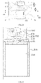
- the outdoor unit 10 may further include a deflector cover 130 arranged on a periphery of the first wind wheel 110 and the second wind wheel 120 to reduce the airflow leakage from the top of the second wind wheel 120 to achieve large air volume and lower noise at a same speed.
- the deflector cover 130 includes a body 131, a first tapering portion 132 connected to an inlet side of the body 131, and a second tapering portion 133 connected to an outlet side of the body 131.
- the body 131 is uniform with a certain diameter along the axial direction.
- the cross-sectional area of the first tapering portion 132 along a direction perpendicular to the axial direction gradually increases towards the heat exchanger 210, and the cross-sectional area of the second tapering portion 133 along a direction perpendicular to the axial direction gradually increases away from the heat exchanger 210 to facilitate the flow of air into and out of the deflector cover 130.
- the first wind wheel 110 is partially arranged in the body 131 and near the inlet side of the body 131, which facilitates the lateral inlet of the first wind wheel 110;
- the second wind wheel 120 is at least partially arranged in the body 131 and near the outlet side of the body 131, which enables the airflow generated by the first wind wheel 110 and the second wind wheel 120 to be channeled through the deflector cover 130.
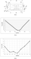
- a relationship between a spacing S2 between an inlet side of the first wind wheel and the inlet side of the body as well as the length H1 of the first wind wheel along the axial direction is configured as: 0.4 ⁇ S 2/ H 1 ⁇ 0.7, for example 0.57 ⁇ S 2/ H 1 ⁇ 0.62 , specifically S 2/ H 1 may be specifically 0.45, 0.5, 0.58, 0.6 or 0.65, etc., leading to the input air of the deflector cover 130 more smooth, with greater air volume and less noise.
- the inlet side of the body 131 is connected to the first tapering portion 132 (the lower end of the cylindrical section in FIG. 3 ), and the outlet side of the body 131 is connected to the second tapering portion 133 (the upper end of the cylindrical section in FIG. 3 ).
- the spacing S3 between the outlet side of the second wind wheel 120 and the outlet side of the body 131 is configured as positive when the air outlet side of the second wind wheel 120 is arranged above the air outlet side of the body 131; the spacing S3 between the air outlet side of the second wind wheel 120 and the air outlet side of the body 131 is configured as negative when the air outlet side of the second wind wheel 120 is arranged below the air outlet side of the body 131.
- a relationship between the spacing S3 between the outlet side of the second wind wheel 120 and the outlet side of the body 131 as well as the length H2 of the second wind wheel 120 along the axial direction is configured as: 0 ⁇
- a relationship between a spacing S3 between the side of the second wind wheel 120 away from the heat exchanger 210 and the side of the body 131 away from the heat exchanger 210, and the length H3 of the second tapering portion 133 in the axial direction is configured as: S 3 ⁇ H 3, so that the first wind wheel 110 and the second wind wheel 120 may achieve a better effect on airflow output and generate large air volume with less noise.
- a relationship between the length H4 of the first tapering portion 132 in the axial direction and the outer diameter D1 of the first wind wheel 110 is configured as: 0.06 ⁇ H 4/ D 1 ⁇ 0.2, for example, H 4/ D 1 may be specifically 0.08, 0.1 or 0.15, so that the first wind wheel 110 may achieve a better effect on airflow input and generate large air volume with low noise.
- a relationship between the distance R1 between the inlet side of the second wind wheel 120 and the outlet side of the first wind wheel 110 in the axial direction and the length R3 of the deflector cover 130 in the axial direction is configured as: 0.7 ⁇ R 1/ R 3 ⁇ 0.95, for example, R1/R3 may be specifically 0.75, 0.8 or 0.9, etc., so that the deflector cover 130 may achieve a better effect on airflow guidance for the airflow generated by the first wind wheel 110 and the second wind wheel 120 and a higher efficiency of the first wind wheel 110 and the second wind wheel 120, which is conductive to increasing the air volume and reducing the noise at the same time.
- the pressure rising distribution ratio between the first wind wheel 110 and the second wind wheel 120 is from 0.6 to 1, for example, 0.76 to 0.84, and can be specifically 0.6, 0.76, 0.8, 0.84 or 1, etc., which enables the air pressure between the first wind wheel 110 and the second wind wheel 120 to be less influential, thus the two wind wheels may operate better.
- the air conditioner outdoor unit 10 further includes a drive component 140 configured to drive the first wind wheel 110 and the second wind wheel 120 to rotate in opposite directions with a small wind speed and radial velocity at the outlet side, which is conducive to air output.
- a drive component 140 configured to drive the first wind wheel 110 and the second wind wheel 120 to rotate in opposite directions with a small wind speed and radial velocity at the outlet side, which is conducive to air output.
- air reversion is less likely to occur, and the air conditioner outdoor unit has strong pressure resistance, which may solve the problem of high pressure drop outside the unit during the installation of a multi-connected air conditioner outdoor unit.
- first wind wheel 110 and the second wind wheel 120 may be driven by two drive components to rotate respectively, without limitation herein.
- the air conditioner outdoor unit including two wind wheels in the present disclosure reaches the same air volume with less speed and power, which may reduce the hardware requirements of the drive component and reduce the noise value as well as improve the sound quality.
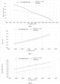
- Table 1 Single wind wheel fan Two wind wheels outdoor unit in the present disclosure Diameter (mm) 700 700 Rotational speed (rpm) 920 460 Air volume (m3/h) 12000 12000 Power (W) 604 561 Noise (dB) 64.2 59.6
- the air conditioner outdoor unit with two wind wheels in the present disclosure has a greater static pressure, transports a greater distance of air, requires less power, and generates less noise, when the same preset air volume is achieved. In addition, with the same rotational frequency, the noise generated is lower.
- the heat exchanger 210 is a U-shaped heat exchanger, and the heat exchanger 210 is formed with a first inlet surface 211, a second inlet surface 212, and a third inlet surface 213.
- the length L1 is arranged in the axial vertical direction on the first inlet surface 211 and in the extension direction of the first inlet surface 211.
- the length L2 is defined in the axial vertical direction on the second inlet surface 212 and in the extension direction of the second inlet surface.
- the length L3 is defined in the vertical direction of the axial direction on the third inlet surface 213 and in the extension direction of the third inlet surface 213.
- a relationship among the outer diameter D1 of the first wind wheel, the length L1 on the first inlet surface, the length L2 on the second inlet surface, and the length L3 on the third inlet surface is configured as: 0.85 D 1 ⁇ L 1 ⁇ L 2 ⁇ 1.5 D 1, 0.85 D 1 ⁇ L 3 ⁇ L 2 ⁇ 1.5 D 1, so that each air inlet surface of the heat exchanger 210 achieves a better effect on airflow input, thereby improving the heat transfer efficiency, and thus being able to cooperate with the first wind wheel 110 and the second wind wheel 120 to achieve a better noise reduction effect.
- the heat exchanger 210 includes multiple fins 214 spaced apart and multiple rows of heat exchanger tubes 215 arranged through the multiple fins 214.
- the multiple fins 214 may be formed with curved louvers (not shown in the figures).
- the number of rows of the heat exchanger tubes 210 is 2 to 3, for example 2, 2.5 (2 rows on one side and 3 rows on the other side) or 3.
- the tube diameter of heat exchanger tubes 215 is 5mm to 9.5mm, such as 6.2mm to 7.3mm, specifically 5mm, 6mm, 6.2mm, 7.3mm or 9.5mm.
- each two adjacent fins 214 is 1.3mm to 1.6mm, such as 1.34mm to 1.48mm, specifically 1.3mm, 1.34mm, 1.4mm, 1.48 mm or 1.6mm.
- the heat exchanger 210 may achieve better heat transfer, thus to cooperate with the first wind wheel 110 and the second wind wheel 120 to achieve better noise reduction.
- the tube diameter of the heat exchanger tube 215 is inversely related to the outer diameter of each two adjacent wind wheels.
- the heat transfer area is configured as the outer surface area of the heat exchanger tube 215 and the fins 214. Since the greater the tube diameter of the heat exchanger tube 215, the greater the heat transfer area of the heat exchanger 210, thereby configuring the tube diameter of the heat exchanger tube 215 in an inverse relationship with the outer diameter of each two adjacent wind wheels may keep a balance between the heat transfer area and the air volume to maintain a certain heat transfer efficiency.
- the number of rows of the heat exchanger tubes 215 is inversely related to the outer diameter of each two adjacent wind wheels. Since the more rows of heat exchanger tubes 215, the greater the heat transfer area of the heat exchanger 210, thereby configuring the number of rows of the heat exchanger tubes 215 in an inverse relationship with the outer diameter of each two adjacent wind wheels may keep a balance between the heat transfer area and the air volume to maintain a certain heat transfer efficiency.
- the spacing of two adjacent fins in multiple fins 214 is inversely related to the outer diameter of each two adjacent wind wheels. Since the greater the spacing of each two adjacent fins in multiple fins 214, the faster the heat transfer of fins 214, thereby configuring the spacing of each two adjacent fins in multiple fins 214 in an inverse relationship with the outer diameter of each two adjacent wind wheels may keep a balance between the heat transfer area and the air volume to maintain a certain heat transfer efficiency.
- the heat exchanger 220 may be a G-shaped heat exchanger, where the heat exchanger 220 is formed with four air inlet surfaces.
- the G shaped heat exchanger has a larger area of the air inlet surface leading to better heater transfer.
- the heat exchanger may be an I-shaped heat exchanger, a V-shaped heat exchanger, or a square-shaped heat exchanger, without limitation herein.
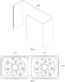
- the air conditioner outdoor unit 10 includes two sets of fan apparatuses 100, a heat exchanger 230, and a housing 320.
- the two sets of fan apparatus 100 and the heat exchanger 230 are arranged in the housing 320, each set of fan apparatus 100 includes a first wind wheel 110, a second wind wheel 120, a deflector cover 130, and a drive component 140.
- Air outlets 321 and 322 are defined on the housing 320.
- the air volume and air pressure may be increased, thereby improving fan efficiency. Further, since the low-frequency sound quality of the fan apparatus 100 with two wind wheels in the present disclosure is better than that of an existing fan apparatus with a single wind wheel, the application of the two sets of fan apparatus 100 may avoid the low-frequency beat vibration noise generated by the coupling of blades of two single wind wheels.
- the heat exchanger 230 is a G-shaped heat exchanger facing the two sets of fan apparatus 100.
- the ratio of the area of a circle, in which the outer diameter of the first wind wheel 110 or the second wind wheel 120 is located, to the area of the inlet surface of the heat exchanger 230 is from 0.052 to 0.089, such as 0.052, 0.06 or 0.089, etc.
- the ratio of the area of the at least two wind wheels to the inlet surface of the heat exchanger 210 may be specifically from 1.18 ⁇ 10 -4 mm -1 to 2.04 ⁇ 10 -4 mm -1 , such as 1.18 ⁇ 10 -4 mm -1 , 1.76 ⁇ 10 -4 mm -1 or 2.04 ⁇ 10 -4 mm -1 , etc., which enables the air volume of the airflow generated by the at least two wind wheels to cooperate better with the heat transfer capacity of the heat exchanger 230, thereby improving the heat transfer efficiency and reducing the noise as well as the energy consumption.
- the area of inlet surface of the heat exchanger 230 is 2.75 ⁇ 10 6 mm 2 to 4.76 ⁇ 10 6 mm 2 , such as 2.75 ⁇ 10 6 mm 2 , 3 ⁇ 10 6 mm 2 or 4.76 ⁇ 10 6 mm 2 , etc., enabling the heat transfer capacity of the heat exchanger 230 to cooperate with the first wind wheel 110 and the second wind wheel 120 to achieve better heat transfer and silent effect.
- the area of inlet surface of the heat exchanger 230 is 1.5 times to 2 times the area of inlet surface of the heat exchanger 210 or the heat exchanger 220 in the above embodiments, such as 1.74 times to 1.87 times, specifically 1.5 times, 1.74 times, 1.8 times, 1.87 times or 2 times.
- the dimensions of the two sets of fan apparatus 100 may be the same or different, for example, the dimensions of the fan apparatus 100 facing three inlet surfaces of the heat exchanger 230 on the right side shown in FIG.17 may be larger than the dimensions of the fan apparatus 100 facing two inlet surfaces of the heat exchanger 230 on the left side, so that the air extraction capacity of the fan apparatus 100 and the heat transfer capacity of the corresponding part of the heat exchanger 230 are matched, thereby improving the heat transfer efficiency and reducing the noise and the energy consumption.
- the two sets of fan apparatus 100 are arranged on a same level to match the heat exchanger 230 with a large area on the inlet side.
- the two sets of fan apparatus 100 may further be arranged coaxially, which may further increase the air pressure and be suitable for special occasions with high static pressure requirements.
- the air conditioner outdoor unit 10 includes a first wind wheel 110, a second wind wheel 120, and a guide lobe 150.
- the first wind wheel 110, the second wind wheel 120, and the guide lobe 150 are arranged axially apart with each other.
- the structures of the first wind wheel 110 and the second wind wheel 120 are mentioned in the above embodiments of the air conditioner outdoor unit 10, and will not be repeated here.
- the guide lobe 150 is arranged on a side of the first wind wheel 110 away from the second wind wheel 120, providing a pre-spin effect to rectify a complex airflow, which may reduce the energy loss of the airflow and improve the air volume.
- the guide lobe 160 may be arranged on a side of the second wind wheel 120 away from the first wind wheel 110.
- the second wind wheel 120 recovers the rotational velocity component of the airflow on the outlet side of the first wind wheel 110 in the circumferential direction by rotating in the opposite direction to the first wind wheel 110.
- the rotational velocity component of the airflow on the outlet side of the second wind wheel 120 is further recovered by the guide lobe 160, so that the airflow may flow out in the axial direction, thereby recovering the dynamic pressure and improving the static pressure, and thus improving the overall air volume and fan efficiency.
- the air conditioner outdoor unit 10 includes a first wind wheel 110, a second wind wheel 120, and a deflector cover 170.
- the structures of the first wind wheel 110 and the second wind wheel 120 are mentioned in above embodiments of the air conditioner outdoor unit 10, and will not be repeated here.
- the deflector cover 170 is configured as a cylindrical shape.
- a blade tip of the wind wheel is a main source of noise, and an outer side of the blade tip of the second wind wheel 120 generates vortex
- the airflow from the outer circumference of the first wind wheel 110 may blow away the vortex at the blade tip of the second wind wheel 120, thereby making a better effect on noise reduction and cooperatively achieving better heat exchange effect with the heat exchanger 210.
- the air conditioner outdoor unit includes a first wind wheel 110, a second wind wheel 120 and a deflector cover 180.
- the structures of the first wind wheel 110 and the second wind wheel 120 are mentioned in the above embodiments of the air conditioner outdoor unit 10, and will not be repeated here.
- a cross-section of a top of the deflector cover 180 along a direction perpendicular to the axial direction is elliptical, which may transform at least a part of the dynamic pressure of the airflow at the top of the deflector cover 180 into static pressure, thereby increasing the pressure difference between the first wind wheel 110 and the second wind wheel 120, and thus improving the overall air volume and reducing the energy consumption and the noise.
- the outer diameter D1 of the first wind wheel is configured as: 560 mm ⁇ D1 ⁇ 850 mm , for example, 630 mm ⁇ D 1 ⁇ 710 mm , which can be specifically 560mm, 630mm, 700mm, 710mm or 850mm, so that the air volume and the air speed of the airflow generated by the first wind wheel 110 may achieve better effect, a better heat exchange effect, silent effect and vibration dissipation effect.
- a relationship among the length H1 of the first wind wheel 110 in the axial direction, the length H2 of the second wind wheel 120 in the axial direction, and the spacing S1 between the first wind wheel 110 and the second wind wheel 120 is configured as: S 1 ⁇ ( H 1 + H 2)/2, for example, S1 can be specifically ( H 1 + H 2)/3, ( H 1 + H 2)/4 or ( H 1 + H 2)/5, etc., which may enable the first wind wheel 110 and the second wind wheel 120 to achieve a better coordination with each other, thereby generating large air volume while low noise.
- the pressure rising distribution ratio between the first wind wheel 110 and the second wind wheel 120 is from 0.6 to 1, for example 0.76 to 0.84, and may be specifically 0.6, 0.76, 0.8, 0.84 or 1, etc., which reduce the influence of air pressure between the first wind wheel 110 and the second wind wheel 120, thereby enabling better operation.
- the following is an example of the above embodiments of the fan apparatus 100 including the first wind wheel 110 and the second wind wheel 120.
- the number of blades of the first wind wheel 110 and the number of blades of the second wind wheel 120 are mutually prime numbers.
- the beat vibration noise generated by the operation of the first wind wheel 110 and the second wind wheel 120 may be reduced, and some of the harmonic noise may be reduced or eliminated to facilitate further noise reduction.
- FIG. 9 illustrates the comparison of the noise volume at different frequencies between the outdoor unit with two wind wheel of the present disclosure and a conventional single wind wheel fan.
- the fan apparatus 100 in the present disclosure has less noise. This is due to the fact that the airflow passing through the conventional single wind wheel fan will produce significant noise.
- the number of blades of the first wind wheel 110 and the number of blades of the second wind wheel 120 are reasonably matched, thereby effectively reducing the noise.
- the difference between the number of blades of the first wind wheel 110 and the number of blades of the second wind wheel 120 is 2.
- the noise produced by the tail flow action of the first wind wheel 110 on a leading edge (near the edge of the first wind wheel 110) of the second wind wheel 120 causes the noise produced by the second wind wheel 120 to be greater than the noise produced by the first wind wheel 110.
- the above design ensures that the number of blades of the second wind wheel 120 is less than that of the first wind wheel 110, which is conducive to reducing the noise produced by the second wind wheel 120, thereby facilitating to reducing the overall noise of the fan apparatus 100.
- the diameter of the first wind wheel 110 (as shown in D1 in FIG. 3 , which is the same below) and the diameter of the second wind wheel 120 (as shown in D2 in FIG. 3 , which is the same below) are both greater than or equal to a first threshold
- the greater between the number of blades of the first wind wheel 110 and the number of blades of the second wind wheel 120 is greater than or equal to a second threshold
- the diameter of the first wind wheel 110 and the diameter of the second wind wheel 120 are both less than the first threshold
- the greater of the number of blades of the first wind wheel 110 and the number of blades of the second wind wheel 120 is less than or equal to a third threshold.
- the second threshold is greater than the third threshold.
- the first threshold is taken in the range of 450 mm to 800 mm, in some embodiment 600 mm, etc.; the second threshold is preferably 9, etc.; and the third threshold is preferably 7, etc.
- the following two problems may be solved: in a first case where the diameter of the first wind wheel 110 and the diameter of the second wind wheel 120 are small while the number of blades of the first wind wheel 110 and the number of blades of the second wind wheel 120 are large, the thickening of the first wind wheel 110 and the second wind wheel 120 is so large that the performance of the first wind wheel 110 and the second wind wheel 120 is decreased; in a second case where the diameter of the first wind wheel 110 and the diameter of the second wind wheel 120 are large while the number of blades of the first wind wheel 110 and the number of blades of the second wind wheel 120 are small, the performance of the first wind wheel 110 and the second wind wheel 120 may not be fully utilized.
- FIG. 32 which including three parts (a), (b), and (c). Shown in (a), the number of blades of the first wind wheel 110 is 9 and the number of blades of the second wind wheel 120 is 7. Shown in (b), the number of blades of the first wind wheel 110 is 7 and the number of blades of the second wind wheel 120 is 9. Shown in (c), the number of blades of the first wind wheel 110 is 5 and the number of blades of the second wind wheel 120 is 7.
- the diameters of the first wind wheel 110 and the second wind wheel 120 in the embodiments may be the same or different, and the number of blades of both satisfy the above relationship.
- the vortex of the blade tip leakage is one of the main sources of the aerodynamic noise of the wind wheel, which means that the second wind wheel 120 is the main source of noise. Therefore, the number of blades of the first wind wheel 110 is greater than the number of blades of the second wind wheel 120, while ensuring the performance of the fan apparatus 100.
- the number of blades of the second wind wheel 120 is less, which may effectively reduce the aerodynamic noise caused by the second wind wheel 120, while the number of blades of the first wind wheel 110 is greater to ensure the performance of the fan apparatus 100 (including air volume, air output efficiency, etc.), which may enable the performance of the fan apparatus 100 to meet the requirements.
- a relationship between the number n1 of blades of the first wind wheel 110 and the number n2 of blades of the second wind wheel 120 is configured as:
- the number of blades of the first wind wheel 110 and the number of blades of the second wind wheel 120 are positively related to their respective diameters. Specifically, the greater the diameter of the first wind wheel 110, the greater the number of blades of the first wind wheel 110; the greater the diameter of the second wind wheel 120, the greater the number of blades of the second wind wheel 120.
- the number of blades of the first wind wheel 110 and the number of blades of the second wind wheel 120 in the embodiments are positively correlated with their respective diameters, so that the number of blades of the first wind wheel 110 and the number of blades of the second wind wheel 120 match with their respective diameters to improve the performance of the first wind wheel 110 and the second wind wheel 120.
- the number of blades of the first wind wheel 110 and the number of blades of the second wind wheel 120 are from 5 to 15. In this way, the production cost of the fan apparatus 100 and the performance of the first wind wheel 110 and the second wind wheel 120 may be optimized.
- the following is an example of the above embodiments of the fan apparatus 100 including the first wind wheel 110 and the second wind wheel 120.
- the fan apparatus 100 further includes a guide lobe 150, which is axially spaced from the first wind wheel 110 and the second wind wheel 120. Further, the guide lobe 150, the first wind wheel 110, and the second wind wheel 120 are arranged coaxially, which means the central axes of the guide lobe 150, the first wind wheel 110 and the second wind wheel 120 coincide.
- the effect of the guide lobe 150 is different depending on different position arranged on the fan apparatus.
- the guide lobe 150 when the guide lobe 150 is arranged on the inlet side, the bending direction of the blades of the guide lobe 150 is opposite to the bending direction of the blades of the first wind wheel 110, and the guide lobe 150 is configured to provide pre-spin, which means to provide pre-spin flow for the incoming airflow from the first wind wheel 110, so as to rectify the complex incoming airflow, thereby reducing energy consumption and increasing air volume; and when the guide lobe 150 is arranged on the outlet side, the bending direction of the blades of the guide lobe 150 is opposite to the bending direction of the blades of the second wind wheel 120, and the guide wheel 150 is configured to recover the rotational velocity component of the airflow passing through the second wind wheel 120, so that the airflow is output along the axial direction of the fan apparatus 100 as much as possible, which is conducive to increasing the static pressure as well as the airflow,
- the number of blades of the first wind wheel 110, the number of blades of the second wind wheel 120, and the number of blades of the guide lobe 150 are mutually prime numbers.
- the number of blades of the first wind wheel 110 is 9, the number of blades of the second wind wheel 120 is 7, the number of blades of the guide lobe 150 is 11, etc.
- the number of blades of the guide lobe 150 is related to the pressure rising effect of the fan apparatus 100, by the design that the number of blades of the first wind wheel 110, the number of blades of the second wind wheel 120 and the number of blades of the guide lobe 150 are mutually prime numbers, the number of blades of the first wind wheel 110, the number of blades of the second wind wheel 120 and the number of blades of the guide lobe 150 match with each other, so that the fan apparatus 100 achieves the best pressure rising effect.
- a relationship among the number n1 of blades of the first wind wheel 110, the number n2 of blades of the second wind wheel 120, and the number n3 of blades of the guide lobe 150 is configured as: n 1 ⁇ n 2, n 2 ⁇ n 3 ⁇ 2 n 1, or n 2 ⁇ n 1, n 1 ⁇ n 3 ⁇ 2 n 2.
- the number of blades of the first wind wheel 110, the number of the blades of the second wind wheel 120 and the number of the blades of the guide lobe satisfy the above relationship, which ensure that the guide lobe 150 has sufficient consistency to ensure that the guide lobe 150 has a good rectification and pressure rising effect.
- the arrangement satisfying the above relationship of the numbers of blades limits the number of new noise sources introduced, which may effectively control the overall noise of the fan apparatus 100.
- a relationship among the number n1 of blades of the first wind wheel 110, the number n2 of blades of the second wind wheel 120, and the number n3 of blades of the guide lobe 150 is configured as: n 2 ⁇ n 1, n 1 ⁇ n 3 ⁇ 2 n 2.
- the first wind wheel 110 is relatively close to the inlet side and the second wind wheel 120 is relatively close to the outlet side, considering that the second wind wheel 120 is the main source of aerodynamic noise, it is conducive to reducing the noise produced by the rotation of the second wind wheel 120 by configuring the number of blades of the second wind wheel 120 less than the number of blades of the first wind wheel 110.
- the performance of the first wind wheel 110 and the second wind wheel 120 are matched, thereby maximizing the performance of the first wind wheel 110 and the second wind wheel 120 while reducing the cost of the fan apparatus 100.
- the number of blades of the guide lobe 150 as shown above, maximizes the pressure rising effect and contributes to improving the performance of the fan apparatus 100.
- the number of blades of the guide lobe 150 is from 6 to 17. In this case, the production cost of the fan apparatus 100 and the performance of the guide lobe 150 may be optimized.
Landscapes
- Engineering & Computer Science (AREA)
- Mechanical Engineering (AREA)
- General Engineering & Computer Science (AREA)
- Chemical & Material Sciences (AREA)
- Combustion & Propulsion (AREA)
- Wind Motors (AREA)
- Other Air-Conditioning Systems (AREA)
Abstract
Description
- The present disclosure claims priority to
Chinese patent application No. 202011080566.1 filed on October 10, 2020 Chinese patent application No. 202022248414.X filed on October 10, 2020 - The present application relates to the technology field of air conditioners, in particular to a fan apparatus and an air conditioner outdoor unit.
- Air conditioner is a kind of a necessary daily used appliance. The function and quality of air conditioners directly affect people's daily life. At present, an axial flow fan system is usually adopted in air conditioners to provide circulating air for an outdoor unit to accelerating heat exchange. The volume of the circulating air is closely related to the performance of the outdoor unit.
- In long-term research, the applicant of the present disclosure finds that a single wind wheel fan system is usually adopted in the outdoor unit of the air conditioner. In the case, an output airflow has a large amount of the rotational speed component along the circumference and the static pressure efficiency is low, leading to more noise generated while air volume increasing. Therefore, the balance of air volume and noise is difficult to keep.
- The present disclosure provides a fan apparatus and an air conditioner outdoor unit to solve the technical problem that the air volume and noise of a single wind wheel fan system of an air conditioner outdoor unit in the prior technology are difficult to be balanced.
- To solve the above technical problems, one technical solution adopted in the present disclosure is to provide a fan apparatus comprising: a first wind wheel and a second wind wheel. The first wind wheel and the second wind wheel are spaced apart axially. A relationship among a spacing S1 between the first wind wheel and the second wind wheel, a length H1 of the first wind wheel along the axial direction and a length H2 of the second wheel along the axial direction is configured as: S1 < (H1 + H2)/2.
- In some embodiments, the spacing S1 of the first wind wheel and the second wind wheel is configured as: 20mm ≤ S1 ≤ 70mm.
- In some embodiments, the fan apparatus further includes a deflector cover, arranged on the periphery of the first wind wheel and the second wind wheel, wherein the deflector cover include a body, wherein the first wind wheel is partially arranged in the body and near an inlet side of the body; the second wind wheel is at least partially arranged in the body and near an outlet side of the body; a relationship between a spacing S2 between an inlet side of the first wind wheel and the inlet side of the body as well as the length H1 of the first wind wheel along the axial direction is configured as: 0.4 <S2/H1 <0.7.
- In some embodiments, a relationship between a spacing S3 between an outlet side of the second wind wheel and the outlet side of the body as well as the length H2 of the second wind wheel along the axial direction is configured as: 0 <S3/H2 <0.25.
- In some embodiments, the body part has the same diameter in the axial direction. The deflector cover includes a first tapering portion connected to the inlet side of the body and a second tapering portion connected to the outlet side of the body; a relationship between a spacing S3 between the outlet of the second wind wheel and the outlet side of the body as well as a length H3 of the second tapering portion along the axial direction is configured as: S3 < H3.
- In some embodiments, a relationship between a length H4 of the first tapering portion along the axial direction and an outer diameter D1 of the first wind wheel is configured as: 0.06 <H4/D1 <0.2.
- In some embodiments, a pressure rising distribution ratio from 0.6 to 1 is defined between the first wind wheel and the second wind wheel.
- In some embodiments, the fan apparatus further includes a guide lobe spaced axially from the first wind wheel and the second wind wheel, wherein a relationship among a length H5 of the guide lobe along the axial direction, the length H1 of the first wind wheel along the axial direction and the length H2 of the second wind wheel along the axial direction is configured as: 0.25(H1 + H2) ≤ H5 ≤ 0.75(H1 + H2).
- In some embodiments, the guide lobe is arranged on a side of the first wind wheel away from the second wind wheel; a relationship among a distance S4 between the guide lobe and the first wind wheel along the axial direction, the length H1 of the first wind wheel along the axial direction and the length H2 of the second wind wheel along the axial direction is configured as: 0.05(H1 + H2) ≤ S4 ≤ 0.25(H1 + H2); or the guide lobe is arranged on a side of the second wind wheel away from the first wind wheel; a relationship among a distance S5 between the guide lobe and the second wind wheel along the axial direction, the length H1 of the first wind wheel along the axial direction and the length H2 of the second wind wheel along the axial direction is configured as: 0.05(H1 + H2) ≤ S5 ≤ 0.25(H1 + H2).
- In some embodiments, fan apparatus includes a guide lobe spaced axially from the first wind wheel and the second wind wheel, wherein a number of blades are included in the first wind wheel, the second wind wheel and the guide lobe; a relationship among the number of the blades n1 in the first wind wheel, the number of the blades n2 in the second wind wheel and the number of the blades n3 in the guide lobe is configured as: n1 ≤ n2, n2 ≤ n3 ≤ 2n1; or n2 ≤ n1,n1 ≤ n3 ≤ 2n2.
- In some embodiments, the guide lobe is arranged on a side of the first wind wheel opposite to the second wind wheel; the bending direction of the blades in the guide lobe is opposite to the bending direction of the blades in the first wind wheel; the side of the first wind wheel opposite to the second wind wheel is an inlet side while the side of the second wind wheel opposite to the first wind wheel is an outlet side.
- In some embodiments, the guide lobe is arranged on a side of the second wind wheel opposite to the first wind wheel; the bending direction of the blades in the guide lobe is opposite to the bending direction of the blades in the second wind wheel; the side of the first wind wheel opposite to the second wind wheel is an inlet side while the side of the second wind wheel opposite to the first wind wheel is an outlet side.
- In some embodiments, the number of the blades in the first wind wheel, the number of the blades in the second wind wheel and the number of the blades in the guide lobe are mutually prime numbers.
- In some embodiments, the number of the blades in the guide lobe 11.
- In some embodiments, the difference between the number of the blades in the first wind wheel and the number of the blades in the second wheel is 2.
- In some embodiments, the diameter of the first wind wheel and the diameter of the second wind wheel are both larger than or equal to a first threshold, and the larger of the number of the blades in the first wind wheel and the number of the blades in the second wind wheel is larger than or equal to a second threshold; or the diameter of the first wind wheel and the diameter of the second wind wheel are both smaller than or equal to a first threshold, and the larger of the number of the blades in the first wind wheel and the number of the blades in the second wind wheel is smaller than or equal to a third threshold; the second threshold is larger than the third threshold.
- In some embodiments, the range of the first threshold is from 450mm to 800mm, the second threshold is 9, and the third threshold is 7.
- In some embodiments, the side of the first wind wheel away from the second wind wheel is an inlet side while the side of the second wind wheel away from the first wind wheel is an outlet side; the number of the blades in the first wind wheel is larger the number of the blades in the second wind wheel.
- In some embodiments, the side of the first wind wheel opposite to the second wind wheel is an inlet side while the side of the second wind wheel opposite to the first wind wheel is an outlet side; a relationship between the number of the blades n1 in the first wind wheel and the number of the blades n2 in the second wind wheel is configured as: |h ∗ n1 - s ∗ n2| ≥ 2, h, s ∈ (1,2,3).
- In some embodiments, the number of the blades in the first wind wheel and the number of the blades in the second wind wheel are each positively related to their respective diameters.
- In some embodiments, the number of the blades in the first wind wheel and the number of the blades in the second wind wheel are each from 5 to 15.
- In some embodiments, the first wind wheel rotates in an opposite direction to the second wind wheel.
- To solve the above technical problems, another technical solution adopted in the present disclosure is to provide an air conditioner outdoor unit, including a fan apparatus and a heat exchanger, the fan apparatus adopted to guide airflow through the heat exchanger. The fan apparatus includes a first wind wheel and a second wind wheel, defined in an axial space; wherein a relationship among a spacing S1 between the first wind wheel and the second wind wheel, a length H1 of the first wind wheel along the axial direction and a length H2 of the second wheel along the axial direction is configured as: S1 < (H1 + H2)/2.
- The present disclosure includes a first wind wheel and a second wind wheel spaced axially apart. The spacing S1 between the first wind wheel and the second wind wheel, the length H1 of the first wind wheel in the axial direction, and the length H2 of the second wind wheel in the axial direction satisfy the following relationship: S1 < (H1 + H2)/2, so that a better coordination relationship may be achieved between the first wind wheel and the second wind wheel, and noise is lower when a relatively large volume of air is generated at relatively low energy consumption.
- In order to more clearly illustrate the technical solutions in the embodiments of the present disclosure, a brief description of the accompanying drawings to be used in the description of the embodiments will be given below. It will be obvious that the accompanying drawings in the following description are only some embodiments of the present disclosure, and that other accompanying drawings may be obtained on the basis of these drawings without any creative effort for those skilled in the art.
-
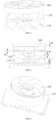
FIG. 1 is a perspective structural schematic view of an air conditioner outdoor unit according to some embodiments of the present disclosure. -
FIG. 2 is a structural cross-sectional schematic view of an air conditioner outdoor unit to some embodiments of the present disclosure. -
FIG. 3 is a partial structural cross-sectional schematic view of an air conditioner outdoor unit according to some embodiments of the present disclosure. -
FIG. 4 is a schematic diagram of a relationship between a position of a first wind wheel in a deflector cover and a change in noise for an air conditioner outdoor unit according to some embodiments of the present disclosure. -
FIG. 5 is a schematic diagram of a relationship between a position of a second wind wheel in the deflector cover and a change in noise for an air conditioner outdoor unit according to some embodiments of the present disclosure. -
FIG. 6 is a schematic diagram of a relationship between an air volume and a change of static pressure in a single wind wheel fan and an outdoor unit with at least two wind wheels according to some embodiments of the present disclosure. -
FIG. 7 is a schematic diagram, of a relationship between an air volume and a change of power in a single wind wheel fan and an air outdoor unit with two wind wheels according to some embodiments of the present disclosure. -
FIG. 8 is a schematic diagram of a relationship between an air volume and a change of noise in a single wind wheel fan and an air outdoor unit some embodiments with two wind wheels according to some embodiments of the present disclosure. -
FIG. 9 is a schematic diagram of the relationship between the frequency and the change of noise in a single wind wheel fan and an air conditioner outdoor unit comprised by two wind wheels according to some embodiments of the present disclosure. -
FIG. 10 is a perspective structural schematic view of a heat exchanger of an air conditioner outdoor unit according to some embodiments of the present disclosure. -
FIG. 11 is an elevated structural schematic view of a heat exchanger of an outdoor unit o according to some embodiments of the present disclosure. -
FIG. 12 is a perspective structural schematic view of a heat exchanger of an air conditioner outdoor unit according to other embodiments of the present disclosure. -
FIG. 13 is an elevated structural schematic view of a heat exchanger of an air conditioner outdoor unit according to other embodiments of the present disclosure. -
FIG. 14 is a perspective structural schematic view of an air conditioner outdoor unit according to other embodiments of the present disclosure. -
FIG. 15 is a structural cross-sectional schematic view of an air conditioner outdoor unit according to other embodiments of the present disclosure. -
FIG. 16 is a perspective structural schematic view of a heat exchanger of an air conditioner outdoor unit according to other embodiments of the present disclosure. -
FIG. 17 is an elevated structural schematic view of a heat exchanger of an air conditioner outdoor unit according to other embodiments of the present disclosure. -
FIG. 18 is a structural cross-sectional schematic view of an air conditioner outdoor unit according to other embodiments of the present disclosure. -
FIG. 19 is a perspective schematic view of a partial structure of an air conditioner outdoor unit according to other embodiments of the present disclosure. -
FIG. 20 is a cross-sectional schematic view of a partial structure of an air conditioner outdoor unit according to other embodiments of the present disclosure. -
FIG. 21 is a structural cross-sectional schematic view of an air conditioner outdoor unit according to other embodiments of the present disclosure. -
FIG. 22 is a perspective schematic view of a partial structure of an air conditioner outdoor unit according to other embodiments of the present disclosure. -
FIG. 23 is a cross-sectional schematic view of a partial structure of an air conditioner outdoor unit according to other embodiments of the present disclosure. -
FIG. 24 is a perspective schematic view of a partial structure of an air conditioner outdoor unit according to other embodiments of the present disclosure. -
FIG. 25 is a front schematic view of a partial structure of an air conditioner outdoor unit according to other embodiments of the present disclosure. -
FIG. 26 is a cross-sectional schematic view of a partial structure of an air conditioner outdoor unit according to other embodiments of the present disclosure. -
FIG. 27 is a top schematic view of a partial structure of an air conditioner outdoor unit according to other embodiments of the present disclosure. -
FIG. 28 is a perspective schematic view of a partial structure of an air conditioner outdoor unit according to other embodiments of the present disclosure. -
FIG. 29 is a front schematic view of a partial structure of an air conditioner outdoor unit according to other embodiments of the present disclosure. -
FIG. 30 is a cross-sectional schematic view of a partial structure of an air conditioner outdoor unit according to other embodiments of the present disclosure. -
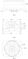
FIG. 31 is a top schematic view of a partial structure of an air conditioner outdoor unit according to other embodiments of the present disclosure. - FIG. 32 is a structural schematic view of a first wind wheel and a second wind wheel according to some embodiments of the present disclosure.
- The technical solutions in the embodiments of the present disclosure will be clearly and completely described below with reference to the specification and drawings in the embodiments of the present disclosure. Obviously, the described embodiments are only a part of the embodiments of the present disclosure, but not all of the embodiments. Based on the embodiments in the present disclosure, all other embodiments obtained by those skilled in the art without creative efforts shall fall within the scope of the present disclosure.
- The terms "first" and "second" in the present disclosure are applied for descriptive purposes only, and are not to be construed as indicating or implying relative importance or implicitly specifying the number of technical features indicated. In the description of the present disclosure, "a plurality of" and "multiple" means at least two, such as two, three, etc., unless otherwise expressly and specifically limited. In addition, the terms "include", "comprise" and "have", and any variations thereof, are intended to cover non-exclusive inclusion. For example, a process, method, system, product or apparatus including a series of steps or units is not limited to the listed steps or units, but optionally further includes steps or units that are not listed, or optionally further includes other steps or units that are inherent to the processes, methods, products or apparatus mentioned above. The term "and/or" is simply a description of the associated relationship of the associated objects, indicating that three relationships may exist, for example, A and/or B, which may mean: A alone, both A and B, and B alone. In addition, the character "/" in the present disclosure indicates that before or after the associated object is an "or" relationship.
- Referring to
FIGS. 1 and 2 , at least two wind wheels and aheat exchanger 210 are included in an air conditioneroutdoor unit 10 according to some embodiments of the present disclosure. The at least two wind wheels are axially spaced apart, and theheat exchanger 210 is arranged facing the at least two wind wheels. The ratio of a distance R1 between a first surface of a first wind wheel of the at least two wind wheels and a second surface of a second wind wheel of the at least two wind wheels in the axial direction and a length R2 of theheat exchanger 210 in the axial direction is from 0.1 to 0.4, such as 0.1, 0.2 or 0.4, etc. The first surface is arranged on a side of the first wind wheel away from the second wind wheel, and the second surface is arranged on a side of the second wind wheel away from the first wind wheel. By providing the at least two wind wheels, an air volume may be increased while keeping a noise within a preset range and a high static pressure efficiency, thereby enabling a fan efficiency to be improved. In addition, by limiting the ratio of the distance between opposite surfaces, of the at least two wind wheels in the axial direction and the length R2 of theheat exchanger 210 in the axial direction, the air volume generated by the at least two wind wheels may match with dimensions of theheat exchanger 210 to achieve better heat transfer, silent effect and vibration dissipation. - In some embodiments, a ratio of the distance R1 between the opposite surfaces of the at least two wind wheels in the axial direction and the length of the
heat exchanger 210 in the axial direction is from 0.28 to 0.39, such as 0.28, 0.33 or 0.39, etc., which further enables the air volume generated by the at least two wind wheels to better match with the dimensions of theheat exchanger 210, thereby achieving better heat transfer, silent effect and vibration dissipation. - In some embodiments, a ratio of a circle area with an outer diameter of each of the at least two wind wheels to an area of an inlet side of the
heat exchanger 210 is from 0.089 to 0.242, such as 0.089, 0.15 or 0.242, etc. A ratio of the outer diameter of at the least two wind wheels to the area of the inlet side of theheat exchanger 210 may be from 2.04 × 10⁻⁴ mm -1 to 3.63 × 10⁻⁴ mm -1, such as 2.04 × 10⁻⁴ mm -1, 3.25 × 10⁻⁴ mm -1 or 3.63 × 10⁻⁴ mm -1, etc. In this way, the air volume of an airflow generated by the at least two wind wheels may better match with a heat transfer capability of theheat exchanger 210, which enables the heat transfer efficiency of the air conditioneroutdoor unit 10 to achieve a better comprehensive effect between heat transfer and energy consumption as well as noise reduction. The area of the inlet side of theheat exchanger 210 may be configured as an area of an inner surface of theheat exchanger 210. - In some embodiments, the outer diameter of the at least two wind wheels is 560mm to 850mm, such as 610mm to 750mm, specifically 560mm, 610mm, 700mm, 750mm or 850mm, so that the air volume and air speed of the airflow generated by the at least two wind wheels may match with the
heat exchanger 210 to achieve better heat transfer, silent effect and vibration dissipation. - In some embodiments, the inlet area of the
heat exchanger 210 is 2.34 × 106 mm 2 to 2.75 × 106 mm 2, such as 2.34 × 106 mm 2, 2.5 × 106 mm 2 or 2.75 × 106 mm 2, etc., so that the heat transfer capacity of theheat exchanger 210 may match with the at least two wind wheels to achieve better heat transfer and silent effect. - In some embodiments, the air conditioner
outdoor unit 10 is in the form of top air outlet, and in other embodiments, the air conditioner outdoor unit may be in the form of bottom air outlet or side air outlet, which is not limited here. - In some embodiments, the spacing S1 of two adjacent wind wheels is configured as: 20mm ≤ S1 ≤ 70mm, such as 20mm, 50mm or 70mm, which may avoid too much air loss from the lower wind wheel caused by a too large spacing of at the least two wind wheels, and may further avoid interference caused by the two adjacent wind wheels, which may lead to damage the wind wheel structure, caused by a too small spacing of at least two wind wheels.
- Referring to
FIG.1, FIG.2 andFIG.3 , in some embodiments, the at least two wind wheels are arranged in afan apparatus 100. The at least two wind wheels include afirst wind wheel 110 and asecond wind wheel 120, and thesecond wind wheel 120 is arranged on a side of thefirst wind wheel 110 away from theheat exchanger 210. Thefirst wind wheel 110 and thesecond wind wheel 120 are arranged coaxially, which means the central axes of the two wind wheels coincide. The rotation direction of thefirst wind wheel 110 is opposite to the rotation direction of thesecond wind wheel 120, and the bending direction of blades of thefirst wind wheel 110 is also opposite to the bending direction of blades of thesecond wind wheel 120, so that the rotation direction of the airflow generated by thefirst wind wheel 110 is opposite to the rotation direction of the airflow generated by the second wind wheel 120 (but the flow direction of the airflow generated by thefirst wind wheel 110 is the same as the flow direction of the airflow generated by the second wind wheel 120). The two wind wheels cancel each other's rotational velocity component of the airflow generated by each other in the circumferential direction, so that the airflow flows along the axial direction of thefan apparatus 100 as much as possible, and the two wind wheels cooperate with each other to produce the airflow along the axial direction of thefan apparatus 100, which is an axial airflow. - In addition, a side of the
first wind wheel 110 away from thesecond wind wheel 120 is an inlet side, and a side of thesecond wind wheel 120 away from thefirst wind wheel 110 is an outlet side. The airflow generated by the rotation of thefirst wind wheel 110 and thesecond wind wheel 120 passes through thefirst wind wheel 110 and thesecond wind wheel 120 in turn from the inlet side, and is then output through the outlet side. - A relationship between the outer diameter D1 of the
first wind wheel 110 and the outer diameter D2 of thesecond wind wheel 120 is configured as: D2 ≥ 0.7D1, for example, D2 = 0.7D1, D2 = D1 or D2 = 1.2D1, so that thefirst wind wheel 110 and thesecond wind wheel 120 may cooperate to produce large volume of air and generate low noise. - When D1 = D2, a relationship between the length H1 of the
first wind wheel 110 in the axial direction and the length H2 of thesecond wind wheel 120 in the axial direction is configured as: 1 ≤ H2/H1 ≤ 1.2, for example, H2/H1 = 1, H2/H1 = 1.1, or H2/H1 = 1.2, etc. By configuring the length H1 of thefirst wind wheel 110 in the axial direction and the length H2 of thesecond wind wheel 120 in the axial direction to be equal, the overall air volume become greater, and the pressure difference distribution between thefirst wind wheel 110 and thesecond wind wheel 120 is also 1:1, which enables the transition of airflow from thefirst wind wheel 110 to thesecond wind wheel 120 to be smoother, leading to better noise reduction effect; by configuring the length H1 of thefirst wind wheel 110 in the axial direction to be less than the length H2 of thesecond wind wheel 120 in the axial direction, the pressure rising effect of thefirst wind wheel 110 may be weakened, such that the airflow may pre-spin better in the lower part of thefirst wind wheel 110. - In some embodiments, by arranging the length H1 of the
first wind wheel 110 in the axial direction and the length H2 of thesecond wind wheel 120 in the axial direction, the pressure rising ratio of thefirst wind wheel 110 and thesecond wind wheel 120 may be matched. The pressure rising distribution ratio of thefirst wind wheel 110 to thesecond wind wheel 120 is from 0.6 to 1, for example 0.76 to 0.84, and may be specifically 0.6, 0.76, 0.8, 0.84, or 1, etc., making the air pressure between thefirst wind wheel 110 and thesecond wind wheel 120 less influential, thus the two wind wheels may be better operated. - When D1 = D2, the spacing S1 between the
first wind wheel 110 and thesecond wind wheel 120 is configured as: 20mm ≤ S1 ≤ 40mm, for example, 26mm ≤ S1 ≤ 32mm, and may be specifically S1 = 20mm, S1 = 26mm, S1 = 30mm, S1 = 32mm or S1 = 40mm, etc., which enable thefirst wind wheel 110 and thesecond wind wheel 120 to achieve a better cooperation relationship, thereby reducing the noise while producing large air volume. - By configuring the outer diameter of the
first wind wheel 110 and thesecond wind wheel 120 to be equal, the air extraction capacities of the two wind wheels are the same, so that the two wind wheels may better match with each other and reduce the noise with large air volume generated. - In some embodiments, a relationship among the length H1 of the
first wind wheel 110 in the axial direction, the length H2 of thesecond wind wheel 120 in the axial direction, and the spacing S1 between thefirst wind wheel 110 and thesecond wind wheel 120 is configured as: S1 < (H1 + H2)/2, for example, S1 may be specifically (H1 + H2)/3, (H1 + H2)/4 or (H1 + H2)/5, etc., which enables thefirst wind wheel 110 and thesecond wind wheel 120 to achieve a better cooperation relationship, thereby producing large air volume with low energy consumption and low noise. - In some embodiments, the
outdoor unit 10 may further include adeflector cover 130 arranged on a periphery of thefirst wind wheel 110 and thesecond wind wheel 120 to reduce the airflow leakage from the top of thesecond wind wheel 120 to achieve large air volume and lower noise at a same speed. - In some embodiments, the
deflector cover 130 includes a body 131, afirst tapering portion 132 connected to an inlet side of the body 131, and asecond tapering portion 133 connected to an outlet side of the body 131.The body 131 is uniform with a certain diameter along the axial direction. The cross-sectional area of thefirst tapering portion 132 along a direction perpendicular to the axial direction gradually increases towards theheat exchanger 210, and the cross-sectional area of thesecond tapering portion 133 along a direction perpendicular to the axial direction gradually increases away from theheat exchanger 210 to facilitate the flow of air into and out of thedeflector cover 130. - In some embodiments, the
first wind wheel 110 is partially arranged in the body 131 and near the inlet side of the body 131, which facilitates the lateral inlet of thefirst wind wheel 110; thesecond wind wheel 120 is at least partially arranged in the body 131 and near the outlet side of the body 131, which enables the airflow generated by thefirst wind wheel 110 and thesecond wind wheel 120 to be channeled through thedeflector cover 130. - Referring further to
FIG. 4 , in some embodiments, a relationship between a spacing S2 between an inlet side of the first wind wheel and the inlet side of the body as well as the length H1 of the first wind wheel along the axial direction is configured as: 0.4 < S2/H1 < 0.7, for example 0.57 < S2/H1 < 0.62 , specifically S2/H1 may be specifically 0.45, 0.5, 0.58, 0.6 or 0.65, etc., leading to the input air of thedeflector cover 130 more smooth, with greater air volume and less noise. In this case, the inlet side of the body 131 is connected to the first tapering portion 132 (the lower end of the cylindrical section inFIG. 3 ), and the outlet side of the body 131 is connected to the second tapering portion 133 (the upper end of the cylindrical section inFIG. 3 ). - Referring further to
FIG. 5 , in some embodiments, the spacing S3 between the outlet side of thesecond wind wheel 120 and the outlet side of the body 131 is configured as positive when the air outlet side of thesecond wind wheel 120 is arranged above the air outlet side of the body 131; the spacing S3 between the air outlet side of thesecond wind wheel 120 and the air outlet side of the body 131 is configured as negative when the air outlet side of thesecond wind wheel 120 is arranged below the air outlet side of the body 131. A relationship between the spacing S3 between the outlet side of thesecond wind wheel 120 and the outlet side of the body 131 as well as the length H2 of thesecond wind wheel 120 along the axial direction is configured as: 0 < |S3/H2| < 0.25, such as, 0.1, 0.15 or 0.2, etc., so that thedeflector cover 130 may achieve a better effect on airflow guidance for the airflow generated by thefirst wind wheel 110 and thesecond wind wheel 120 and produce low noise. - In some embodiments, a relationship between a spacing S3 between the side of the
second wind wheel 120 away from theheat exchanger 210 and the side of the body 131 away from theheat exchanger 210, and the length H3 of thesecond tapering portion 133 in the axial direction is configured as: S3 < H3, so that thefirst wind wheel 110 and thesecond wind wheel 120 may achieve a better effect on airflow output and generate large air volume with less noise. - In some embodiments, a relationship between the length H4 of the
first tapering portion 132 in the axial direction and the outer diameter D1 of thefirst wind wheel 110 is configured as: 0.06 < H4/D1 < 0.2, for example, H4/D1 may be specifically 0.08, 0.1 or 0.15, so that thefirst wind wheel 110 may achieve a better effect on airflow input and generate large air volume with low noise. - In some embodiments, a relationship between the distance R1 between the inlet side of the
second wind wheel 120 and the outlet side of thefirst wind wheel 110 in the axial direction and the length R3 of thedeflector cover 130 in the axial direction is configured as: 0.7 < R1/R3 < 0.95, for example, R1/R3 may be specifically 0.75, 0.8 or 0.9, etc., so that thedeflector cover 130 may achieve a better effect on airflow guidance for the airflow generated by thefirst wind wheel 110 and thesecond wind wheel 120 and a higher efficiency of thefirst wind wheel 110 and thesecond wind wheel 120, which is conductive to increasing the air volume and reducing the noise at the same time. - In some embodiments, the pressure rising distribution ratio between the
first wind wheel 110 and thesecond wind wheel 120 is from 0.6 to 1, for example, 0.76 to 0.84, and can be specifically 0.6, 0.76, 0.8, 0.84 or 1, etc., which enables the air pressure between thefirst wind wheel 110 and thesecond wind wheel 120 to be less influential, thus the two wind wheels may operate better. - In some embodiments, the air conditioner
outdoor unit 10 further includes adrive component 140 configured to drive thefirst wind wheel 110 and thesecond wind wheel 120 to rotate in opposite directions with a small wind speed and radial velocity at the outlet side, which is conducive to air output. In addition, air reversion is less likely to occur, and the air conditioner outdoor unit has strong pressure resistance, which may solve the problem of high pressure drop outside the unit during the installation of a multi-connected air conditioner outdoor unit. - In other embodiments, the
first wind wheel 110 and thesecond wind wheel 120 may be driven by two drive components to rotate respectively, without limitation herein. - Referring to Table 1, assuming that a diameter of the
first wind wheel 110 and thesecond wind wheel 120 is 700mm, compared with a single wind wheel fan, the air conditioner outdoor unit including two wind wheels in the present disclosure reaches the same air volume with less speed and power, which may reduce the hardware requirements of the drive component and reduce the noise value as well as improve the sound quality.Table 1 Single wind wheel fan Two wind wheels outdoor unit in the present disclosure Diameter (mm) 700 700 Rotational speed (rpm) 920 460 Air volume (m3/h) 12000 12000 Power (W) 604 561 Noise (dB) 64.2 59.6 - Referring to
FIGS. 6 to 9 , compared with the single wind wheel fan, the air conditioner outdoor unit with two wind wheels in the present disclosure has a greater static pressure, transports a greater distance of air, requires less power, and generates less noise, when the same preset air volume is achieved. In addition, with the same rotational frequency, the noise generated is lower. - Referring together to
FIGS. 10 and11 , in some embodiments, theheat exchanger 210 is a U-shaped heat exchanger, and theheat exchanger 210 is formed with afirst inlet surface 211, asecond inlet surface 212, and athird inlet surface 213. The length L1 is arranged in the axial vertical direction on thefirst inlet surface 211 and in the extension direction of thefirst inlet surface 211. The length L2 is defined in the axial vertical direction on thesecond inlet surface 212 and in the extension direction of the second inlet surface. The length L3 is defined in the vertical direction of the axial direction on thethird inlet surface 213 and in the extension direction of thethird inlet surface 213. A relationship among the outer diameter D1 of the first wind wheel, the length L1 on the first inlet surface, the length L2 on the second inlet surface, and the length L3 on the third inlet surface is configured as: 0.85D1 < L1 < L2 < 1.5D1, 0.85D1 < L3 < L2 < 1.5D1, so that each air inlet surface of theheat exchanger 210 achieves a better effect on airflow input, thereby improving the heat transfer efficiency, and thus being able to cooperate with thefirst wind wheel 110 and thesecond wind wheel 120 to achieve a better noise reduction effect. - In some embodiments, the
heat exchanger 210 includesmultiple fins 214 spaced apart and multiple rows ofheat exchanger tubes 215 arranged through themultiple fins 214. Themultiple fins 214 may be formed with curved louvers (not shown in the figures). The number of rows of theheat exchanger tubes 210 is 2 to 3, for example 2, 2.5 (2 rows on one side and 3 rows on the other side) or 3. The tube diameter ofheat exchanger tubes 215 is 5mm to 9.5mm, such as 6.2mm to 7.3mm, specifically 5mm, 6mm, 6.2mm, 7.3mm or 9.5mm. The spacing of each twoadjacent fins 214 is 1.3mm to 1.6mm, such as 1.34mm to 1.48mm, specifically 1.3mm, 1.34mm, 1.4mm, 1.48 mm or 1.6mm. In this case, theheat exchanger 210 may achieve better heat transfer, thus to cooperate with thefirst wind wheel 110 and thesecond wind wheel 120 to achieve better noise reduction. - In some embodiments, the tube diameter of the
heat exchanger tube 215 is inversely related to the outer diameter of each two adjacent wind wheels. In addition, the heat transfer area is configured as the outer surface area of theheat exchanger tube 215 and thefins 214. Since the greater the tube diameter of theheat exchanger tube 215, the greater the heat transfer area of theheat exchanger 210, thereby configuring the tube diameter of theheat exchanger tube 215 in an inverse relationship with the outer diameter of each two adjacent wind wheels may keep a balance between the heat transfer area and the air volume to maintain a certain heat transfer efficiency. - In some embodiments, the number of rows of the
heat exchanger tubes 215 is inversely related to the outer diameter of each two adjacent wind wheels. Since the more rows ofheat exchanger tubes 215, the greater the heat transfer area of theheat exchanger 210, thereby configuring the number of rows of theheat exchanger tubes 215 in an inverse relationship with the outer diameter of each two adjacent wind wheels may keep a balance between the heat transfer area and the air volume to maintain a certain heat transfer efficiency. - In some embodiments, the spacing of two adjacent fins in
multiple fins 214 is inversely related to the outer diameter of each two adjacent wind wheels. Since the greater the spacing of each two adjacent fins inmultiple fins 214, the faster the heat transfer offins 214, thereby configuring the spacing of each two adjacent fins inmultiple fins 214 in an inverse relationship with the outer diameter of each two adjacent wind wheels may keep a balance between the heat transfer area and the air volume to maintain a certain heat transfer efficiency. - Referring to
FIGS. 12 and 13 , in other embodiment, theheat exchanger 220 may be a G-shaped heat exchanger, where theheat exchanger 220 is formed with four air inlet surfaces. The G shaped heat exchanger has a larger area of the air inlet surface leading to better heater transfer. - In other embodiments, the heat exchanger may be an I-shaped heat exchanger, a V-shaped heat exchanger, or a square-shaped heat exchanger, without limitation herein.
- Referring to
FIGS. 14 to 17 , in other embodiments of the present disclosure, the air conditioneroutdoor unit 10 includes two sets offan apparatuses 100, aheat exchanger 230, and ahousing 320. The two sets offan apparatus 100 and theheat exchanger 230 are arranged in thehousing 320, each set offan apparatus 100 includes afirst wind wheel 110, asecond wind wheel 120, adeflector cover 130, and adrive component 140.Air outlets housing 320. For the structures of thefirst wind wheel 110, thesecond wind wheel 120, thedeflector cover 130 and thedrive components 140, references may be made in the embodiments above, which will not be repeated here. By arranging the two sets offan apparatus 100 in the air conditioneroutdoor unit 10, the air volume and air pressure may be increased, thereby improving fan efficiency. Further, since the low-frequency sound quality of thefan apparatus 100 with two wind wheels in the present disclosure is better than that of an existing fan apparatus with a single wind wheel, the application of the two sets offan apparatus 100 may avoid the low-frequency beat vibration noise generated by the coupling of blades of two single wind wheels. - In some embodiments, the
heat exchanger 230 is a G-shaped heat exchanger facing the two sets offan apparatus 100. The ratio of the area of a circle, in which the outer diameter of thefirst wind wheel 110 or thesecond wind wheel 120 is located, to the area of the inlet surface of theheat exchanger 230 is from 0.052 to 0.089, such as 0.052, 0.06 or 0.089, etc. The ratio of the area of the at least two wind wheels to the inlet surface of theheat exchanger 210 may be specifically from 1.18 × 10⁻⁴ mm -1 to 2.04 × 10⁻⁴ mm -1, such as 1.18 × 10⁻⁴ mm -1, 1.76 × 10⁻⁴ mm -1 or 2.04 × 10⁻⁴ mm -1, etc., which enables the air volume of the airflow generated by the at least two wind wheels to cooperate better with the heat transfer capacity of theheat exchanger 230, thereby improving the heat transfer efficiency and reducing the noise as well as the energy consumption. - In some embodiments, the area of inlet surface of the
heat exchanger 230 is 2.75 × 106 mm 2 to 4.76 × 106 mm 2, such as 2.75 × 106 mm 2, 3 × 106 mm 2 or 4.76 × 106 mm 2, etc., enabling the heat transfer capacity of theheat exchanger 230 to cooperate with thefirst wind wheel 110 and thesecond wind wheel 120 to achieve better heat transfer and silent effect. - In some embodiments, the area of inlet surface of the
heat exchanger 230 is 1.5 times to 2 times the area of inlet surface of theheat exchanger 210 or theheat exchanger 220 in the above embodiments, such as 1.74 times to 1.87 times, specifically 1.5 times, 1.74 times, 1.8 times, 1.87 times or 2 times. - In some embodiments, the dimensions of the two sets of
fan apparatus 100 may be the same or different, for example, the dimensions of thefan apparatus 100 facing three inlet surfaces of theheat exchanger 230 on the right side shown inFIG.17 may be larger than the dimensions of thefan apparatus 100 facing two inlet surfaces of theheat exchanger 230 on the left side, so that the air extraction capacity of thefan apparatus 100 and the heat transfer capacity of the corresponding part of theheat exchanger 230 are matched, thereby improving the heat transfer efficiency and reducing the noise and the energy consumption. - In some embodiments, the two sets of
fan apparatus 100 are arranged on a same level to match theheat exchanger 230 with a large area on the inlet side. In other embodiments, the two sets offan apparatus 100 may further be arranged coaxially, which may further increase the air pressure and be suitable for special occasions with high static pressure requirements. - Referring to
FIGS 18 to 20 , in other embodiments of the present disclosure, the air conditioneroutdoor unit 10 includes afirst wind wheel 110, asecond wind wheel 120, and aguide lobe 150. Thefirst wind wheel 110, thesecond wind wheel 120, and theguide lobe 150 are arranged axially apart with each other. The structures of thefirst wind wheel 110 and thesecond wind wheel 120 are mentioned in the above embodiments of the air conditioneroutdoor unit 10, and will not be repeated here. - In some embodiments, a relationship among a length H5 of the
guide lobe 150 along the axial direction, the length H1 of thefirst wind wheel 110 along the axial direction, and the length H2 of thesecond wind wheel 120 along the axial direction is configured as: 0.25(H1 + H2) ≤ H5 ≤ 0.75(H1 + H2), for example, 0.48(H1 + H2) ≤ H5 ≤ 0.62(H1 + H2), which may be specifically H5 = 0.25 (H1 + H2), H5 = 0.48(H1 + H2), H5 = 0.5(H1 + H2), H5 = 0.25(H1 + H2) or H5 = 0.75(H1 + H2), thereby enabling theguide lobe 150 to match with thefirst wind wheel 110 and thesecond wind wheel 120 to achieve a better effect on airflow guidance, and thus achieve a better heat exchange effect, silent effect and vibration dissipation effect. - In some embodiments, the
guide lobe 150 is arranged on a side of thefirst wind wheel 110 away from thesecond wind wheel 120, providing a pre-spin effect to rectify a complex airflow, which may reduce the energy loss of the airflow and improve the air volume. - In some embodiments, a relationship among a distance S4 between the
guide lobe 150 and thefirst wind wheel 110 along the axial direction, the length H1 of thefirst wind wheel 110 along the axial direction, and the length H2 of thesecond wind wheel 120 along the axial direction is configured as: 0.05(H1 + H2) ≤ S4 ≤ 0.25(H1 + H2), for example, 0.11(H1 + H2) ≤ S4 ≤ 0.19(H1 + H2), which may be specifically S4 = 0.05(H1 + H2),S4 = 0.11(H1 + H2), S4 = 0.15(H1 + H2), S4 = 0.19(H1 + H2), or S4 = 0.25(H1 + H2), which may avoid poorer flow guidance due to the distance between theguide lobe 150 and thefirst wind wheel 110 being too far, or avoid damaging the structure of theguide lobe 150 or thefirst wind wheel 110 due to interference caused by the distance between theguide lobe 150 and thefirst wind wheel 110 being too close. - Referring to
FIGS. 21 to 23 , in other embodiments, theguide lobe 160 may be arranged on a side of thesecond wind wheel 120 away from thefirst wind wheel 110. Thesecond wind wheel 120 recovers the rotational velocity component of the airflow on the outlet side of thefirst wind wheel 110 in the circumferential direction by rotating in the opposite direction to thefirst wind wheel 110. The rotational velocity component of the airflow on the outlet side of thesecond wind wheel 120 is further recovered by theguide lobe 160, so that the airflow may flow out in the axial direction, thereby recovering the dynamic pressure and improving the static pressure, and thus improving the overall air volume and fan efficiency. - In some embodiments, a relationship among a distance S5 between the
guide lobe 160 and thesecond wind wheel 120 along the axial direction, the length H1 of thefirst wind wheel 110 along the axial direction, and the length H2 of thesecond wind wheel 120 along the axial direction is configured as: 0.05(H1 + H2) ≤ S5 ≤ 0.25(H1 + H2), for example, 0.11(H1 + H2) ≤ S5 ≤ 0.19(H1 + H2), which can be specifically S5 = 0.05(H1 + H2), S5 = 0.11(H1 + H2), S5 = 0.15(H1 + H2), S5 = 0.19(H1 + H2) or S5 = 0.25(H1 + H2), which may avoid poorer flow guidance due to the distance between theguide lobe 150 and thesecond wind wheel 120 being too far, or avoid damaging the structure of theguide lobe 150 or thesecond wind wheel 120 due to interference caused by the distance between theguide lobe 150 and thesecond wind wheel 120 being too close. - Referring to
FIGS. 24 to 27 , in other embodiments of the present disclosure, the air conditioneroutdoor unit 10 includes afirst wind wheel 110, asecond wind wheel 120, and adeflector cover 170. The structures of thefirst wind wheel 110 and thesecond wind wheel 120 are mentioned in above embodiments of the air conditioneroutdoor unit 10, and will not be repeated here. - In some embodiments, the
deflector cover 170 is configured as a cylindrical shape. A relationship among the outer diameter D1 of thefirst wind wheel 110, the outer diameter D2 of thesecond wind wheel 120, the length H1 of thefirst wind wheel 110 in the axial direction, and the length H2 of thesecond wind wheel 120 in the axial direction is configured as: 1.01 ≤ D1/D2 ≤ 1.03, 1 ≤ H2/H1 ≤ 1.15, such as D1/D2 = 1.01, D1/D2 = 1.02 or D1/D2 = 1.03, etc., and H2/H1 = 1, H2/H1 = 1.1 or H2/H1 = 1.15, etc. Since a blade tip of the wind wheel is a main source of noise, and an outer side of the blade tip of thesecond wind wheel 120 generates vortex, by configuring the outer diameter of thefirst wind wheel 110 to be greater than the outer diameter of thesecond wind wheel 120, the airflow from the outer circumference of thefirst wind wheel 110 may blow away the vortex at the blade tip of thesecond wind wheel 120, thereby making a better effect on noise reduction and cooperatively achieving better heat exchange effect with theheat exchanger 210. - Referring to
FIGS. 28 to 31 , in other embodiments of the present disclosure, the air conditioner outdoor unit includes afirst wind wheel 110, asecond wind wheel 120 and adeflector cover 180. The structures of thefirst wind wheel 110 and thesecond wind wheel 120 are mentioned in the above embodiments of the air conditioneroutdoor unit 10, and will not be repeated here. - In some embodiments, a cross-section of a top of the
deflector cover 180 along a direction perpendicular to the axial direction is elliptical, which may transform at least a part of the dynamic pressure of the airflow at the top of thedeflector cover 180 into static pressure, thereby increasing the pressure difference between thefirst wind wheel 110 and thesecond wind wheel 120, and thus improving the overall air volume and reducing the energy consumption and the noise. - In some embodiments, a relationship between the outer diameter D1 of the
first wind wheel 110 and the long axis D3 of thedeflector cover 180 is configured as: 1.04 ≤ D3/D1 ≤ 1.1, such as D3/D1 = 1.04, D3/D1 = 1.08 or D3/D1 = 1.1, etc., so that thedeflector cover 180 may better guide the airflow generated by thefirst wind wheel 110 and thesecond wind wheel 120, thus achieving a better heat transfer effect, silent effect and vibration dissipation effect. - In some embodiments, a relationship between the outer diameter D1 of the
first wind wheel 110 and the long axis D3 of thedeflector cover 180 is configured as: 1.06 ≤ D3/D1 ≤ 1.08, such as, D3/D1 = 1.06, D3/D1 = 1.07 or D3/D1 = 1.08, etc., so that thedeflector cover 180 may better guide the airflow generated by thefirst wind wheel 110 and thesecond wind wheel 120, thus achieving a better heat transfer effect, silent effect and vibration dissipation effect. - In some embodiments, a relationship between the outer diameter D1 of the
first wind wheel 110 and the short axis D4 of thedeflector cover 180 is configured as: 1.02 ≤ D4/D1 ≤ 1.05, such as D4/D1 = 1.02, D4/D1 = 1.03 or D4/D1 = 1.05, etc., so that thedeflector cover 180 may better guide the airflow generated by thefirst wind wheel 110 and thesecond wind wheel 120, thus achieving a better heat transfer effect, silent effect and vibration dissipation effect. - In some embodiments, a relationship between the outer diameter D1 of the
first wind wheel 110, and the outer diameter D2 of thesecond wind wheel 120 is configured as: D2 ≥ 0.7D1, for example, D2 = 0.7D1, D2 = D1, or D2 = 1.2D1, enabling thefirst wind wheel 110 to cooperate with the second wind wheel to produce large air volume and generate low noise. - In some embodiments, the outer diameter D1 of the first wind wheel is configured as: 560mm ≤ D1 ≤ 850mm, for example, 630mm ≤ D1 ≤ 710mm, which can be specifically 560mm, 630mm, 700mm, 710mm or 850mm, so that the air volume and the air speed of the airflow generated by the
first wind wheel 110 may achieve better effect, a better heat exchange effect, silent effect and vibration dissipation effect. - In some embodiments, a relationship between the outer diameter D1 of the
first wind wheel 110 and a hub diameter D11 of thefirst wind wheel 110 is configured as: 2 ≤ D1/D11 ≤ 4.5, for example, 3.3 ≤ D1/D11 ≤ 4.1, specifically D1/D11 = 2, D1/D11 = 3, D1/D11 = 3.3, D1/D11 = 4.1 or D1/D11 = 4.5, etc., so that the structure of thefirst wind wheel 110 may achieve a better matching effect with thedeflector cover 180. - In some embodiments, a relationship between the outer diameter D2 of the
second wind wheel 120 and a hub diameter D21 of thesecond wind wheel 120 is configured as: 2 ≤ D2/D21 ≤ 4.5, for example, 3.4 ≤ D2/D21 ≤ 4.2 , specifically D2/D21 = 2, D2/D21 = 3, D2/D21 = 3.4, D2/D21 = 4.2 or D21 D21 = 4.5, etc., so that the structure of thefirst wind wheel 120 may achieve a better matching effect with thedeflector cover 180. - In some embodiments, a relationship among the length H1 of the
first wind wheel 110 in the axial direction, the length H2 of thesecond wind wheel 120 in the axial direction, and the spacing S1 between thefirst wind wheel 110 and thesecond wind wheel 120 is configured as: S1 < (H1 + H2)/2, for example, S1 can be specifically (H1 + H2)/3, (H1 + H2)/4 or (H1 + H2)/5, etc., which may enable thefirst wind wheel 110 and thesecond wind wheel 120 to achieve a better coordination with each other, thereby generating large air volume while low noise. - In some embodiments, the pressure rising distribution ratio between the
first wind wheel 110 and thesecond wind wheel 120 is from 0.6 to 1, for example 0.76 to 0.84, and may be specifically 0.6, 0.76, 0.8, 0.84 or 1, etc., which reduce the influence of air pressure between thefirst wind wheel 110 and thesecond wind wheel 120, thereby enabling better operation. - Referring further to
FIG. 2 , the following is an example of the above embodiments of thefan apparatus 100 including thefirst wind wheel 110 and thesecond wind wheel 120. - In some embodiments, the number of blades of the
first wind wheel 110 and the number of blades of thesecond wind wheel 120 are mutually prime numbers. In this case, the beat vibration noise generated by the operation of thefirst wind wheel 110 and thesecond wind wheel 120 may be reduced, and some of the harmonic noise may be reduced or eliminated to facilitate further noise reduction. - Referring together to
FIG. 9 , which illustrates the comparison of the noise volume at different frequencies between the outdoor unit with two wind wheel of the present disclosure and a conventional single wind wheel fan. According to the schematic diagram, with the same frequency, thefan apparatus 100 in the present disclosure has less noise. This is due to the fact that the airflow passing through the conventional single wind wheel fan will produce significant noise. In comparison, the number of blades of thefirst wind wheel 110 and the number of blades of thesecond wind wheel 120 are reasonably matched, thereby effectively reducing the noise. - In some embodiments, the difference between the number of blades of the
first wind wheel 110 and the number of blades of thesecond wind wheel 120 is 2. Specifically, a relationship between the number n1 of blades of thefirst wind wheel 110 and the number n2 of blades of thesecond wind wheel 120 is configured as: n1 > n2, n1 = n2 + 2, or n1 < n2, n2 = n1 + 2. - According to an analysis of a basic theory of pneumatic noise and practical engineering experience, when the number of blades of two adjacent wind wheels (i.e., the
first wind wheel 110 and the second wind wheel 120) connected in series axially satisfies the above relationship, the noise generated by mutual interference between the two wind wheels is low, which is conducive to reducing the pneumatic noise of thefan apparatus 100. - In particular, the noise produced by the tail flow action of the
first wind wheel 110 on a leading edge (near the edge of the first wind wheel 110) of thesecond wind wheel 120 causes the noise produced by thesecond wind wheel 120 to be greater than the noise produced by thefirst wind wheel 110. The above design ensures that the number of blades of thesecond wind wheel 120 is less than that of thefirst wind wheel 110, which is conducive to reducing the noise produced by thesecond wind wheel 120, thereby facilitating to reducing the overall noise of thefan apparatus 100. - In addition, when the diameter of the first wind wheel 110 (as shown in D1 in
FIG. 3 , which is the same below) and the diameter of the second wind wheel 120 (as shown in D2 inFIG. 3 , which is the same below) are both greater than or equal to a first threshold, the greater between the number of blades of thefirst wind wheel 110 and the number of blades of thesecond wind wheel 120 is greater than or equal to a second threshold; or when the diameter of thefirst wind wheel 110 and the diameter of thesecond wind wheel 120 are both less than the first threshold, the greater of the number of blades of thefirst wind wheel 110 and the number of blades of thesecond wind wheel 120 is less than or equal to a third threshold. In addition, the second threshold is greater than the third threshold. - For example, the first threshold is taken in the range of 450 mm to 800 mm, in some
embodiment 600 mm, etc.; the second threshold is preferably 9, etc.; and the third threshold is preferably 7, etc. Specifically, when the diameter of thefirst wind wheel 110 and the diameter of thesecond wind wheel 120 are both greater than or equal to 600mm, n1 = 9, n2 = 7 or n1 = 7, n2 = 9, etc.; and when the diameter of thefirst wind wheel 110 and the diameter of thesecond wind wheel 120 are both less than 600mm, n1 = 7, n2 = 5 or n1 = 5, n2 = 7, etc. - Based on the method above, the following two problems may be solved: in a first case where the diameter of the
first wind wheel 110 and the diameter of thesecond wind wheel 120 are small while the number of blades of thefirst wind wheel 110 and the number of blades of thesecond wind wheel 120 are large, the thickening of thefirst wind wheel 110 and thesecond wind wheel 120 is so large that the performance of thefirst wind wheel 110 and thesecond wind wheel 120 is decreased; in a second case where the diameter of thefirst wind wheel 110 and the diameter of thesecond wind wheel 120 are large while the number of blades of thefirst wind wheel 110 and the number of blades of thesecond wind wheel 120 are small, the performance of thefirst wind wheel 110 and thesecond wind wheel 120 may not be fully utilized. - Referring to FIG. 32, which including three parts (a), (b), and (c). Shown in (a), the number of blades of the
first wind wheel 110 is 9 and the number of blades of thesecond wind wheel 120 is 7. Shown in (b), the number of blades of thefirst wind wheel 110 is 7 and the number of blades of thesecond wind wheel 120 is 9. Shown in (c), the number of blades of thefirst wind wheel 110 is 5 and the number of blades of thesecond wind wheel 120 is 7. - It should be noted that the diameters of the
first wind wheel 110 and thesecond wind wheel 120 in the embodiments may be the same or different, and the number of blades of both satisfy the above relationship. - In some embodiments, considering a presence of the leakage vortex of a blade tip of the second wind wheel 120 (i.e., the vortex is generated on the outer side of the blade tip of the second wind wheel 120), the vortex of the blade tip leakage is one of the main sources of the aerodynamic noise of the wind wheel, which means that the
second wind wheel 120 is the main source of noise. Therefore, the number of blades of thefirst wind wheel 110 is greater than the number of blades of thesecond wind wheel 120, while ensuring the performance of thefan apparatus 100. Therefore, the number of blades of thesecond wind wheel 120 is less, which may effectively reduce the aerodynamic noise caused by thesecond wind wheel 120, while the number of blades of thefirst wind wheel 110 is greater to ensure the performance of the fan apparatus 100 (including air volume, air output efficiency, etc.), which may enable the performance of thefan apparatus 100 to meet the requirements. - In other embodiments, a relationship between the number n1 of blades of the
first wind wheel 110 and the number n2 of blades of thesecond wind wheel 120 is configured as: |h ∗ n1 - s ∗ n2| ≥ 2, h, s ∈ (1,2,3). Therefore, the noise caused by mutual interference between thefirst wind wheel 110 and thesecond wind wheel 120 may be maintained at a minimum level, and the beat vibration may be avoided as much as possible. - In some embodiments, the number of blades of the
first wind wheel 110 and the number of blades of thesecond wind wheel 120 are positively related to their respective diameters. Specifically, the greater the diameter of thefirst wind wheel 110, the greater the number of blades of thefirst wind wheel 110; the greater the diameter of thesecond wind wheel 120, the greater the number of blades of thesecond wind wheel 120. - At a certain rotation speed, with the diameter of the wind wheel greater and the number of blades greater, the air volume is greater. Therefore, the number of blades of the
first wind wheel 110 and the number of blades of thesecond wind wheel 120 in the embodiments are positively correlated with their respective diameters, so that the number of blades of thefirst wind wheel 110 and the number of blades of thesecond wind wheel 120 match with their respective diameters to improve the performance of thefirst wind wheel 110 and thesecond wind wheel 120. - In some embodiments, the number of blades of the
first wind wheel 110 and the number of blades of thesecond wind wheel 120 are from 5 to 15. In this way, the production cost of thefan apparatus 100 and the performance of thefirst wind wheel 110 and thesecond wind wheel 120 may be optimized. - Referring to
FIGS. 18 to 23 , the following is an example of the above embodiments of thefan apparatus 100 including thefirst wind wheel 110 and thesecond wind wheel 120. - In some embodiments, the
fan apparatus 100 further includes aguide lobe 150, which is axially spaced from thefirst wind wheel 110 and thesecond wind wheel 120. Further, theguide lobe 150, thefirst wind wheel 110, and thesecond wind wheel 120 are arranged coaxially, which means the central axes of theguide lobe 150, thefirst wind wheel 110 and thesecond wind wheel 120 coincide. - The effect of the
guide lobe 150 is different depending on different position arranged on the fan apparatus. For example, when theguide lobe 150 is arranged on the inlet side, the bending direction of the blades of theguide lobe 150 is opposite to the bending direction of the blades of thefirst wind wheel 110, and theguide lobe 150 is configured to provide pre-spin, which means to provide pre-spin flow for the incoming airflow from thefirst wind wheel 110, so as to rectify the complex incoming airflow, thereby reducing energy consumption and increasing air volume; and when theguide lobe 150 is arranged on the outlet side, the bending direction of the blades of theguide lobe 150 is opposite to the bending direction of the blades of thesecond wind wheel 120, and theguide wheel 150 is configured to recover the rotational velocity component of the airflow passing through thesecond wind wheel 120, so that the airflow is output along the axial direction of thefan apparatus 100 as much as possible, which is conducive to increasing the static pressure as well as the airflow, thereby improving the efficiency of thefan apparatus 100. This will be described in detail below. - In some embodiments, the number of blades of the
first wind wheel 110, the number of blades of thesecond wind wheel 120, and the number of blades of theguide lobe 150 are mutually prime numbers. For example, the number of blades of thefirst wind wheel 110 is 9, the number of blades of thesecond wind wheel 120 is 7, the number of blades of theguide lobe 150 is 11, etc. - Based on the method above, since the number of blades of the
guide lobe 150 is related to the pressure rising effect of thefan apparatus 100, by the design that the number of blades of thefirst wind wheel 110, the number of blades of thesecond wind wheel 120 and the number of blades of theguide lobe 150 are mutually prime numbers, the number of blades of thefirst wind wheel 110, the number of blades of thesecond wind wheel 120 and the number of blades of theguide lobe 150 match with each other, so that thefan apparatus 100 achieves the best pressure rising effect. - In some embodiments, a relationship among the number n1 of blades of the
first wind wheel 110, the number n2 of blades of thesecond wind wheel 120, and the number n3 of blades of theguide lobe 150 is configured as: n1 ≤ n2, n2 ≤ n3 ≤ 2n1, or n2 ≤ n1, n1 ≤ n3 ≤ 2n2. Based on the practical engineering experience, the number of blades of thefirst wind wheel 110, the number of the blades of thesecond wind wheel 120 and the number of the blades of the guide lobe satisfy the above relationship, which ensure that theguide lobe 150 has sufficient consistency to ensure that theguide lobe 150 has a good rectification and pressure rising effect. In addition, the arrangement satisfying the above relationship of the numbers of blades limits the number of new noise sources introduced, which may effectively control the overall noise of thefan apparatus 100. - Preferably, a relationship among the number n1 of blades of the
first wind wheel 110, the number n2 of blades of thesecond wind wheel 120, and the number n3 of blades of theguide lobe 150 is configured as: n2 ≤ n1, n1 ≤ n3 ≤ 2n2. In this case, since thefirst wind wheel 110 is relatively close to the inlet side and thesecond wind wheel 120 is relatively close to the outlet side, considering that thesecond wind wheel 120 is the main source of aerodynamic noise, it is conducive to reducing the noise produced by the rotation of thesecond wind wheel 120 by configuring the number of blades of thesecond wind wheel 120 less than the number of blades of thefirst wind wheel 110. Further, in the case that the number of blades of thefirst wind wheel 110 is equal to the number of blades of thesecond wind wheel 120, the performance of thefirst wind wheel 110 and thesecond wind wheel 120 are matched, thereby maximizing the performance of thefirst wind wheel 110 and thesecond wind wheel 120 while reducing the cost of thefan apparatus 100. In addition, the number of blades of theguide lobe 150, as shown above, maximizes the pressure rising effect and contributes to improving the performance of thefan apparatus 100. - In an embodiment, the number of blades of the
guide lobe 150 is from 6 to 17. In this case, the production cost of thefan apparatus 100 and the performance of theguide lobe 150 may be optimized. - The above is only some embodiments of the present disclosure, not to limit the scope of the present disclosure. Any equivalent structure or equivalent process transformation using the contents and the accompanying drawings of the present disclosure, or directly or indirectly applied in other related technical fields, are included in the scope of the present disclosure.
Claims (23)
- A fan apparatus, comprising:a first wind wheel and a second wind wheel, axially spaced apart from each other;wherein a relationship among a spacing S1 between the first wind wheel and the second wind wheel, a length H1 of the first wind wheel along the axial direction, and a length H2 of the second wheel along the axial direction is configured as: S1 < (H1 + H2)/2.
- The fan apparatus according to claim 1, wherein the spacing S1 is configured as: 20mm ≤ S1 ≤ 70mm.
- The fan apparatus according to claim 1, wherein the fan apparatus further comprises a deflector cover, arranged on a periphery of the first wind wheel and the second wind wheel; wherein the deflector cover comprise a body, and the first wind wheel is partially arranged in the body and near an inlet side of the body; the second wind wheel is at least partially arranged in the body and near an outlet side of the body; a relationship between a spacing S2 between an inlet side of the first wind wheel and the inlet side of the body and the length H1 of the first wind wheel along the axial direction is configured as: 0.4 <S2/H1 <0.7.
- The fan apparatus according to claim 3, wherein a relationship between a spacing S3 between an outlet side of the second wind wheel and the outlet side of the body and the length H2 of the second wind wheel along the axial direction is configured as: 0 <S3/H2 <0.25.
- The fan apparatus according to claim 3, wherein the body is uniform with a certain diameter along the axial direction; the deflector cover comprises a first tapering portion connected to the inlet side of the body and a second tapering portion connected to the outlet side of the body; a relationship between a spacing S3 between the outlet side of the second wind wheel and the outlet side of the body and a length H3 of the second tapering portion along the axial direction is configured as: S3 < H3.
- The fan apparatus according to claim 5, wherein a relationship between a length H4 of the first tapering portion along the axial direction and an outer diameter D1 of the first wind wheel is configured as: 0.06 <H4/D1 <0.2.
- The fan apparatus according to claim 1, wherein a pressure rising distribution ratio between the first wind wheel and the second wind wheel is from 0.6 to 1.
- The fan apparatus according to claim 1, wherein the fan apparatus further comprises a guide lobe axially spaced apart from the first wind wheel and the second wind wheel, wherein a relationship among a length H5 of the guide lobe along the axial direction, the length H1 of the first wind wheel along the axial direction, and the length H2 of the second wind wheel along the axial direction is configured as:

- The fan apparatus according to claim 8, wherein the guide lobe is arranged on a side of the first wind wheel away from the second wind wheel; a relationship among a distance S4 between the guide lobe and the first wind wheel along the axial direction, the length H1 of the first wind wheel along the axial direction, and the length H2 of the second wind wheel along the axial direction is configured as:

wherein the guide lobe is arranged on a side of the second wind wheel away from the first wind wheel; a relationship among a distance S5 between the guide lobe and the second wind wheel along the axial direction, the length H1 of the first wind wheel along the axial direction, and the length H2 of the second wind wheel along the axial direction is configured as: 0.05 (H1 + H2) ≤ S5 ≤ 0.25 (H1 + H2). - The fan apparatus according to claim 1, wherein the fan apparatus further comprises a guide lobe axially spaced apart from the first wind wheel and the second wind wheel, wherein each of the first wind wheel, the second wind wheel, and the guide lobe comprises a plurality of blades; a relationship among the number n1 of the plurality of blades in the first wind wheel, the number n2 of the plurality of blades in the second wind wheel, and the number n3 of the plurality of blades in the guide lobe is configured as:


- The fan apparatus according to claim 10, wherein the guide lobe is arranged on a side of the first wind wheel away from the second wind wheel; a bending direction of the plurality of blades in the guide lobe is opposite to a bending direction of the plurality of blades in the first wind wheel; the side of the first wind wheel away from the second wind wheel is an inlet side, and a side of the second wind wheel away from the first wind wheel is an outlet side.
- The fan apparatus according to claim 10, wherein the guide lobe is arranged on a side of the second wind wheel away from the first wind wheel; a bending direction of the plurality of blades in the guide lobe is opposite to a bending direction of the plurality of blades in the second wind wheel; a side of the first wind wheel away from the second wind wheel is an inlet side, and the side of the second wind wheel away from the first wind wheel is an outlet side.
- The fan apparatus according to claim 10, wherein the number of the plurality of blades in the first wind wheel, the number of the plurality of blades in the second wind wheel, and the number of the plurality of blades in the guide lobe are mutually prime numbers.
- The fan apparatus according to claim 10, wherein the number of the plurality of blades in the guide lobe is 11.
- The fan apparatus according to claim 10, wherein a difference between the number of the plurality of blades in the first wind wheel and the number of the plurality of blades in the second wheel is 2.
- The fan apparatus according to claim 15, wherein a diameter of the first wind wheel and a diameter of the second wind wheel are each greater than or equal to a first threshold, and a greater value between the number of the plurality of blades in the first wind wheel and the number of the plurality of blades in the second wind wheel is greater than or equal to a second threshold; or the diameter of the first wind wheel and the diameter of the second wind wheel are each less than or equal to the first threshold, and a greater value between the number of the plurality of blades in the first wind wheel and the number of the plurality of blades in the second wind wheel is less than or equal to a third threshold; the second threshold is greater than the third threshold.
- The fan apparatus according to claim 16, wherein the first threshold is in a range from 450mm to 800mm, the second threshold is 9, and the third threshold is 7.
- The fan apparatus according to claim 10, wherein a side of the first wind wheel away from the second wind wheel is an inlet side, and a side of the second wind wheel away from the first wind wheel is an outlet side; the number of the plurality of blades in the first wind wheel is greater than the number of the plurality of blades in the second wind wheel.
- The fan apparatus according to claim 10, wherein a side of the first wind wheel away from the second wind wheel is an inlet side, and a side of the second wind wheel away from the first wind wheel is an outlet side; a relationship between the number n1 of the plurality of blades in the first wind wheel and the number n2 of the plurality of blades in the second wind wheel is configured as:

- The fan apparatus according to claim 10, wherein the number of the plurality of blades in the first wind wheel is positively related to the diameter of the first wind wheel; the number of the plurality of blades in the second wind wheel is positively related to the diameter of the second wind wheel.
- The fan apparatus according to claim 10, wherein the number of the plurality of blades in the first wind wheel and the number of the plurality of blades in the second wind wheel are each from 5 to 15.
- The fan apparatus according to claim 10, wherein a rotation direction of the first wind wheel is opposite to a rotation direction of the second wind wheel.
- An air conditioner outdoor unit, comprising a fan apparatus and a heat exchanger; wherein the fan apparatus is configured to guide an airflow to pass through the heat exchanger, and comprises:
a first wind wheel and a second wind wheel, axially spaced apart from each other; wherein a relationship among a spacing S1 between the first wind wheel and the second wind wheel, a length H1 of the first wind wheel along the axial direction and a length H2 of the second wheel along the axial direction is configured as: S1 < (H1 + H2)/2.
Applications Claiming Priority (3)
| Application Number | Priority Date | Filing Date | Title |
|---|---|---|---|
| CN202022248414.XU CN213808152U (en) | 2020-10-10 | 2020-10-10 | Fan unit and air conditioner outdoor unit |
| CN202011080566.1A CN114320958B (en) | 2020-10-10 | 2020-10-10 | Fan device and air conditioner outdoor unit |
| PCT/CN2021/121841 WO2022073454A1 (en) | 2020-10-10 | 2021-09-29 | Fan apparatus and air conditioner outdoor unit |
Publications (3)
| Publication Number | Publication Date |
|---|---|
| EP4130483A1 true EP4130483A1 (en) | 2023-02-08 |
| EP4130483A4 EP4130483A4 (en) | 2023-11-22 |
| EP4130483B1 EP4130483B1 (en) | 2026-03-18 |
Family
ID=81127109
Family Applications (1)
| Application Number | Title | Priority Date | Filing Date |
|---|---|---|---|
| EP21876972.7A Active EP4130483B1 (en) | 2020-10-10 | 2021-09-29 | Fan apparatus and air conditioner outdoor unit |
Country Status (3)
| Country | Link |
|---|---|
| US (1) | US12221977B2 (en) |
| EP (1) | EP4130483B1 (en) |
| WO (1) | WO2022073454A1 (en) |
Family Cites Families (26)
| Publication number | Priority date | Publication date | Assignee | Title |
|---|---|---|---|---|
| DD201491B1 (en) * | 1981-12-01 | 1987-07-15 | Horst Kolb | AIR VALVE FOR TEXTILE FLOW DRYERS |
| JP2954539B2 (en) * | 1996-08-09 | 1999-09-27 | 川崎重工業株式会社 | Tandem cascade |
| JP4862482B2 (en) * | 2006-05-15 | 2012-01-25 | 株式会社デンソー | Blower |
| US8029236B2 (en) * | 2006-06-08 | 2011-10-04 | Delta Electronics, Inc. | Heat dissipation fan |
| US7874796B2 (en) * | 2006-06-08 | 2011-01-25 | Delta Electronics Inc. | Heat dissipation module |
| JP5273475B2 (en) * | 2008-09-02 | 2013-08-28 | 日本電産株式会社 | Inline axial fan |
| JP5211027B2 (en) * | 2009-12-14 | 2013-06-12 | 国立大学法人 東京大学 | Counter-rotating axial fan |
| JP2013047462A (en) * | 2011-08-29 | 2013-03-07 | Hitachi Ltd | Fan module and server equipment |
| JP6385752B2 (en) | 2013-12-02 | 2018-09-05 | 三星電子株式会社Samsung Electronics Co.,Ltd. | Outdoor unit for blower and air conditioner |
| CN204458511U (en) * | 2015-01-23 | 2015-07-08 | 浙江远大机电有限公司 | High-pressure axial flow fan impeller |
| CN204900286U (en) * | 2015-07-24 | 2015-12-23 | 广东美的制冷设备有限公司 | Axial fan and air conditioner who has it |
| CN106481598B (en) | 2016-12-26 | 2020-10-02 | 珠海格力电器股份有限公司 | Impeller assembly and axial flow fan |
| CN106968973A (en) * | 2017-05-09 | 2017-07-21 | 美的集团股份有限公司 | Axial flow blower |
| CN111043063B (en) * | 2018-10-15 | 2021-06-18 | 广东美的白色家电技术创新中心有限公司 | Counter-rotating fan |
| CN209558544U (en) | 2019-01-08 | 2019-10-29 | 广东美的制冷设备有限公司 | Air conditioner |
| CN109958637B (en) | 2019-04-22 | 2024-09-24 | 广东美的制冷设备有限公司 | Fan assembly of air conditioner outdoor unit and air conditioner outdoor unit having the same |
| CN210688514U (en) | 2019-09-06 | 2020-06-05 | 广东美的制冷设备有限公司 | Air conditioner outdoor unit and air conditioner |
| CN111174338A (en) | 2020-02-19 | 2020-05-19 | 广东美的制冷设备有限公司 | Air conditioner outdoor unit and air conditioner |
| CN111442372A (en) * | 2020-05-14 | 2020-07-24 | 广东美的制冷设备有限公司 | Machine and air conditioner in wind wheel subassembly, air conditioning |
| CN111649005B (en) * | 2020-05-30 | 2024-06-14 | 浙江科贸实业有限公司 | Axial flow fan and air duct for air conditioning |
| CN213810898U (en) * | 2020-10-10 | 2021-07-27 | 广东美的暖通设备有限公司 | An air conditioner outdoor unit |
| CN213808155U (en) * | 2020-10-10 | 2021-07-27 | 广东美的暖通设备有限公司 | Fan unit and air conditioner outdoor unit |
| CN213808156U (en) * | 2020-10-10 | 2021-07-27 | 广东美的暖通设备有限公司 | Fan unit and air conditioner outdoor unit |
| CN213808152U (en) * | 2020-10-10 | 2021-07-27 | 广东美的暖通设备有限公司 | Fan unit and air conditioner outdoor unit |
| CN213808180U (en) * | 2020-10-10 | 2021-07-27 | 广东美的暖通设备有限公司 | Fan device and air conditioner outdoor unit |
| CN213808153U (en) * | 2020-10-10 | 2021-07-27 | 广东美的暖通设备有限公司 | Fan unit and air conditioner outdoor unit |
-
2021
- 2021-09-29 EP EP21876972.7A patent/EP4130483B1/en active Active
- 2021-09-29 WO PCT/CN2021/121841 patent/WO2022073454A1/en not_active Ceased
-
2022
- 2022-11-22 US US17/992,806 patent/US12221977B2/en active Active
Also Published As
| Publication number | Publication date |
|---|---|
| US12221977B2 (en) | 2025-02-11 |
| US20230078022A1 (en) | 2023-03-16 |
| EP4130483B1 (en) | 2026-03-18 |
| EP4130483A4 (en) | 2023-11-22 |
| WO2022073454A1 (en) | 2022-04-14 |
Similar Documents
| Publication | Publication Date | Title |
|---|---|---|
| CN105526691B (en) | Air guide components and axial flow cabinets | |
| CN114320977B (en) | A fan device and an air conditioner outdoor unit | |
| EP4130483B1 (en) | Fan apparatus and air conditioner outdoor unit | |
| CN213810898U (en) | An air conditioner outdoor unit | |
| CN117267156A (en) | Axial flow blades, fan components, air conditioning outdoor units and air conditioners | |
| CN214788140U (en) | Multi-wing centrifugal fan and wind power equipment | |
| CN213808180U (en) | Fan device and air conditioner outdoor unit | |
| CN106766045A (en) | Air-supply assembly and air-conditioner | |
| CN115758629A (en) | High-speed centrifugal fan special for sweeping robot and design method and device thereof | |
| CN114320958B (en) | Fan device and air conditioner outdoor unit | |
| CN114322112B (en) | An air conditioner outdoor unit | |
| CN114320957B (en) | Fan device and air conditioner outdoor unit | |
| CN213540832U (en) | Impeller, fan and range hood | |
| CN116624423A (en) | Efficient stamping impeller | |
| CN210688476U (en) | Air conditioner indoor unit and air conditioner | |
| CN219587825U (en) | Wind wheel and bathroom heater | |
| CN208935015U (en) | Novel fan blade | |
| CN207935154U (en) | Axial-flow windwheel and air conditioner | |
| CN207935153U (en) | Axial-flow windwheel and air conditioner | |
| CN221526757U (en) | Air outlet blade and air conditioner | |
| CN221444450U (en) | Flow guide ring, flow guide ring assembly thereof and air conditioner | |
| CN101900131A (en) | Cross-flow wind wheel and air device comprising same | |
| CN110299814A (en) | Accelerate pressure electrode device layer by layer | |
| CN222067116U (en) | An electric fan | |
| CN201874879U (en) | Cross flow wind wheel and air equipment with same |
Legal Events
| Date | Code | Title | Description |
|---|---|---|---|
| STAA | Information on the status of an ep patent application or granted ep patent |
Free format text: STATUS: THE INTERNATIONAL PUBLICATION HAS BEEN MADE |
|
| PUAI | Public reference made under article 153(3) epc to a published international application that has entered the european phase |
Free format text: ORIGINAL CODE: 0009012 |
|
| STAA | Information on the status of an ep patent application or granted ep patent |
Free format text: STATUS: REQUEST FOR EXAMINATION WAS MADE |
|
| 17P | Request for examination filed |
Effective date: 20221103 |
|
| AK | Designated contracting states |
Kind code of ref document: A1 Designated state(s): AL AT BE BG CH CY CZ DE DK EE ES FI FR GB GR HR HU IE IS IT LI LT LU LV MC MK MT NL NO PL PT RO RS SE SI SK SM TR |
|
| REG | Reference to a national code |
Ref country code: DE Ref legal event code: R079 Free format text: PREVIOUS MAIN CLASS: F04D0025080000 Ipc: F04D0019000000 Ref document number: 602021050352 Country of ref document: DE |
|
| A4 | Supplementary search report drawn up and despatched |
Effective date: 20231020 |
|
| RIC1 | Information provided on ipc code assigned before grant |
Ipc: F24F 1/38 20110101ALI20231016BHEP Ipc: F04D 29/54 20060101ALI20231016BHEP Ipc: F04D 19/00 20060101AFI20231016BHEP |
|
| DAV | Request for validation of the european patent (deleted) | ||
| DAX | Request for extension of the european patent (deleted) | ||
| GRAP | Despatch of communication of intention to grant a patent |
Free format text: ORIGINAL CODE: EPIDOSNIGR1 |
|
| STAA | Information on the status of an ep patent application or granted ep patent |
Free format text: STATUS: GRANT OF PATENT IS INTENDED |
|
| INTG | Intention to grant announced |
Effective date: 20251219 |
|
| GRAS | Grant fee paid |
Free format text: ORIGINAL CODE: EPIDOSNIGR3 |
|
| GRAA | (expected) grant |
Free format text: ORIGINAL CODE: 0009210 |
|
| STAA | Information on the status of an ep patent application or granted ep patent |
Free format text: STATUS: THE PATENT HAS BEEN GRANTED |
|
| AK | Designated contracting states |
Kind code of ref document: B1 Designated state(s): AL AT BE BG CH CY CZ DE DK EE ES FI FR GB GR HR HU IE IS IT LI LT LU LV MC MK MT NL NO PL PT RO RS SE SI SK SM TR |
|
| REG | Reference to a national code |
Ref country code: CH Ref legal event code: F10 Free format text: ST27 STATUS EVENT CODE: U-0-0-F10-F00 (AS PROVIDED BY THE NATIONAL OFFICE) Effective date: 20260318 Ref country code: GB Ref legal event code: FG4D |
|
| REG | Reference to a national code |
Ref country code: IE Ref legal event code: FG4D |
|
| REG | Reference to a national code |
Ref country code: DE Ref legal event code: R096 Ref document number: 602021050352 Country of ref document: DE |