EP4130479A1 - Accumulator - Google Patents
Accumulator Download PDFInfo
- Publication number
- EP4130479A1 EP4130479A1 EP21776677.3A EP21776677A EP4130479A1 EP 4130479 A1 EP4130479 A1 EP 4130479A1 EP 21776677 A EP21776677 A EP 21776677A EP 4130479 A1 EP4130479 A1 EP 4130479A1
- Authority
- EP
- European Patent Office
- Prior art keywords
- outlet pipe
- accumulator
- compression unit
- refrigerant
- main body
- Prior art date
- Legal status (The legal status is an assumption and is not a legal conclusion. Google has not performed a legal analysis and makes no representation as to the accuracy of the status listed.)
- Withdrawn
Links
Images






Classifications
-
- F—MECHANICAL ENGINEERING; LIGHTING; HEATING; WEAPONS; BLASTING
- F25—REFRIGERATION OR COOLING; COMBINED HEATING AND REFRIGERATION SYSTEMS; HEAT PUMP SYSTEMS; MANUFACTURE OR STORAGE OF ICE; LIQUEFACTION SOLIDIFICATION OF GASES
- F25B—REFRIGERATION MACHINES, PLANTS OR SYSTEMS; COMBINED HEATING AND REFRIGERATION SYSTEMS; HEAT PUMP SYSTEMS
- F25B43/00—Arrangements for separating or purifying gases or liquids; Arrangements for vaporising the residuum of liquid refrigerant, e.g. by heat
- F25B43/006—Accumulators
-
- F—MECHANICAL ENGINEERING; LIGHTING; HEATING; WEAPONS; BLASTING
- F04—POSITIVE - DISPLACEMENT MACHINES FOR LIQUIDS; PUMPS FOR LIQUIDS OR ELASTIC FLUIDS
- F04C—ROTARY-PISTON, OR OSCILLATING-PISTON, POSITIVE-DISPLACEMENT MACHINES FOR LIQUIDS; ROTARY-PISTON, OR OSCILLATING-PISTON, POSITIVE-DISPLACEMENT PUMPS
- F04C23/00—Combinations of two or more pumps, each being of rotary-piston or oscillating-piston type, specially adapted for elastic fluids; Pumping installations specially adapted for elastic fluids; Multi-stage pumps specially adapted for elastic fluids
- F04C23/008—Hermetic pumps
-
- F—MECHANICAL ENGINEERING; LIGHTING; HEATING; WEAPONS; BLASTING
- F04—POSITIVE - DISPLACEMENT MACHINES FOR LIQUIDS; PUMPS FOR LIQUIDS OR ELASTIC FLUIDS
- F04C—ROTARY-PISTON, OR OSCILLATING-PISTON, POSITIVE-DISPLACEMENT MACHINES FOR LIQUIDS; ROTARY-PISTON, OR OSCILLATING-PISTON, POSITIVE-DISPLACEMENT PUMPS
- F04C29/00—Component parts, details or accessories of pumps or pumping installations, not provided for in groups F04C18/00 - F04C28/00
- F04C29/06—Silencing
-
- F—MECHANICAL ENGINEERING; LIGHTING; HEATING; WEAPONS; BLASTING
- F04—POSITIVE - DISPLACEMENT MACHINES FOR LIQUIDS; PUMPS FOR LIQUIDS OR ELASTIC FLUIDS
- F04C—ROTARY-PISTON, OR OSCILLATING-PISTON, POSITIVE-DISPLACEMENT MACHINES FOR LIQUIDS; ROTARY-PISTON, OR OSCILLATING-PISTON, POSITIVE-DISPLACEMENT PUMPS
- F04C29/00—Component parts, details or accessories of pumps or pumping installations, not provided for in groups F04C18/00 - F04C28/00
- F04C29/12—Arrangements for admission or discharge of the working fluid, e.g. constructional features of the inlet or outlet
-
- F—MECHANICAL ENGINEERING; LIGHTING; HEATING; WEAPONS; BLASTING
- F04—POSITIVE - DISPLACEMENT MACHINES FOR LIQUIDS; PUMPS FOR LIQUIDS OR ELASTIC FLUIDS
- F04C—ROTARY-PISTON, OR OSCILLATING-PISTON, POSITIVE-DISPLACEMENT MACHINES FOR LIQUIDS; ROTARY-PISTON, OR OSCILLATING-PISTON, POSITIVE-DISPLACEMENT PUMPS
- F04C18/00—Rotary-piston pumps specially adapted for elastic fluids
- F04C18/30—Rotary-piston pumps specially adapted for elastic fluids having the characteristics covered by two or more of groups F04C18/02, F04C18/08, F04C18/22, F04C18/24, F04C18/48, or having the characteristics covered by one of these groups together with some other type of movement between co-operating members
- F04C18/34—Rotary-piston pumps specially adapted for elastic fluids having the characteristics covered by two or more of groups F04C18/02, F04C18/08, F04C18/22, F04C18/24, F04C18/48, or having the characteristics covered by one of these groups together with some other type of movement between co-operating members having the movement defined in group F04C18/08 or F04C18/22 and relative reciprocation between the co-operating members
- F04C18/356—Rotary-piston pumps specially adapted for elastic fluids having the characteristics covered by two or more of groups F04C18/02, F04C18/08, F04C18/22, F04C18/24, F04C18/48, or having the characteristics covered by one of these groups together with some other type of movement between co-operating members having the movement defined in group F04C18/08 or F04C18/22 and relative reciprocation between the co-operating members with vanes reciprocating with respect to the outer member
-
- F—MECHANICAL ENGINEERING; LIGHTING; HEATING; WEAPONS; BLASTING
- F04—POSITIVE - DISPLACEMENT MACHINES FOR LIQUIDS; PUMPS FOR LIQUIDS OR ELASTIC FLUIDS
- F04C—ROTARY-PISTON, OR OSCILLATING-PISTON, POSITIVE-DISPLACEMENT MACHINES FOR LIQUIDS; ROTARY-PISTON, OR OSCILLATING-PISTON, POSITIVE-DISPLACEMENT PUMPS
- F04C2240/00—Components
- F04C2240/80—Other components
- F04C2240/804—Accumulators for refrigerant circuits
-
- F—MECHANICAL ENGINEERING; LIGHTING; HEATING; WEAPONS; BLASTING
- F04—POSITIVE - DISPLACEMENT MACHINES FOR LIQUIDS; PUMPS FOR LIQUIDS OR ELASTIC FLUIDS
- F04C—ROTARY-PISTON, OR OSCILLATING-PISTON, POSITIVE-DISPLACEMENT MACHINES FOR LIQUIDS; ROTARY-PISTON, OR OSCILLATING-PISTON, POSITIVE-DISPLACEMENT PUMPS
- F04C2240/00—Components
- F04C2240/80—Other components
- F04C2240/806—Pipes for fluids; Fittings therefor
-
- F—MECHANICAL ENGINEERING; LIGHTING; HEATING; WEAPONS; BLASTING
- F04—POSITIVE - DISPLACEMENT MACHINES FOR LIQUIDS; PUMPS FOR LIQUIDS OR ELASTIC FLUIDS
- F04C—ROTARY-PISTON, OR OSCILLATING-PISTON, POSITIVE-DISPLACEMENT MACHINES FOR LIQUIDS; ROTARY-PISTON, OR OSCILLATING-PISTON, POSITIVE-DISPLACEMENT PUMPS
- F04C2270/00—Control; Monitoring or safety arrangements
- F04C2270/12—Vibration
-
- F—MECHANICAL ENGINEERING; LIGHTING; HEATING; WEAPONS; BLASTING
- F04—POSITIVE - DISPLACEMENT MACHINES FOR LIQUIDS; PUMPS FOR LIQUIDS OR ELASTIC FLUIDS
- F04C—ROTARY-PISTON, OR OSCILLATING-PISTON, POSITIVE-DISPLACEMENT MACHINES FOR LIQUIDS; ROTARY-PISTON, OR OSCILLATING-PISTON, POSITIVE-DISPLACEMENT PUMPS
- F04C2270/00—Control; Monitoring or safety arrangements
- F04C2270/13—Noise
-
- F—MECHANICAL ENGINEERING; LIGHTING; HEATING; WEAPONS; BLASTING
- F04—POSITIVE - DISPLACEMENT MACHINES FOR LIQUIDS; PUMPS FOR LIQUIDS OR ELASTIC FLUIDS
- F04C—ROTARY-PISTON, OR OSCILLATING-PISTON, POSITIVE-DISPLACEMENT MACHINES FOR LIQUIDS; ROTARY-PISTON, OR OSCILLATING-PISTON, POSITIVE-DISPLACEMENT PUMPS
- F04C23/00—Combinations of two or more pumps, each being of rotary-piston or oscillating-piston type, specially adapted for elastic fluids; Pumping installations specially adapted for elastic fluids; Multi-stage pumps specially adapted for elastic fluids
- F04C23/001—Combinations of two or more pumps, each being of rotary-piston or oscillating-piston type, specially adapted for elastic fluids; Pumping installations specially adapted for elastic fluids; Multi-stage pumps specially adapted for elastic fluids of similar working principle
-
- F—MECHANICAL ENGINEERING; LIGHTING; HEATING; WEAPONS; BLASTING
- F25—REFRIGERATION OR COOLING; COMBINED HEATING AND REFRIGERATION SYSTEMS; HEAT PUMP SYSTEMS; MANUFACTURE OR STORAGE OF ICE; LIQUEFACTION SOLIDIFICATION OF GASES
- F25B—REFRIGERATION MACHINES, PLANTS OR SYSTEMS; COMBINED HEATING AND REFRIGERATION SYSTEMS; HEAT PUMP SYSTEMS
- F25B2400/00—Component parts or details not otherwise provided for in this subclass
- F25B2400/07—Details of compressors or related parts
-
- F—MECHANICAL ENGINEERING; LIGHTING; HEATING; WEAPONS; BLASTING
- F25—REFRIGERATION OR COOLING; COMBINED HEATING AND REFRIGERATION SYSTEMS; HEAT PUMP SYSTEMS; MANUFACTURE OR STORAGE OF ICE; LIQUEFACTION SOLIDIFICATION OF GASES
- F25B—REFRIGERATION MACHINES, PLANTS OR SYSTEMS; COMBINED HEATING AND REFRIGERATION SYSTEMS; HEAT PUMP SYSTEMS
- F25B2500/00—Problems to be solved
- F25B2500/18—Optimization, e.g. high integration of refrigeration components
Definitions
- the present disclosure relates to an accumulator.
- an outlet pipe of an accumulator for a twin rotary compressor has an inverted U-shape, an upper portion is bent, and two lower portions are coupled to respective inlet pipes of the compressor.
- An upper portion of the outlet pipe is cut at the bent portion housed in the internal space of the accumulator in order to suction the refrigerant.
- the refrigerant passing through the outlet pipe of the accumulator flows downward from an opening in the upper portion toward the compressor.
- the refrigerant may flow backward through the two outlet pipes from the compressor.
- the refrigerant flows upward through the two lower portions of the outlet pipes, joins at the upper portion of the outlet pipes, and is discharged from the cut opening into the internal space of the accumulator. This discharged refrigerant causes the issue of large vibrations of the accumulator.
- An accumulator is an accumulator arranged on an inlet side of a rotary compressor including a first compression unit and a second compression unit.
- the accumulator includes a main body casing, a first outlet pipe, a second outlet pipe, and a coupling portion.
- the main body casing includes an upper body portion and a lower body portion.
- the first outlet pipe and the second outlet pipe penetrate through the lower body portion from the main body casing and extend toward the first compression unit and the second compression unit, respectively.
- the coupling portion is coupled to an upper end of the first outlet pipe and an upper end of the second outlet pipe in the main body casing.
- the coupling portion is provided with a joining portion and an extension portion.
- the joining portion joins refrigerants flowing upward through the first outlet pipe and the second outlet pipe.
- the extension portion has a tubular shape extending upward from the joining portion.
- the refrigerants join at the joining portion, pass through the extension portion, and are discharged from the upper end of the extension portion into the internal space of the accumulator. Therefore, the refrigerant is straightened in the process of passing through the extension portion. As a result, the accumulator is not largely vibrated.
- the accumulator according to a second aspect is the accumulator according to the first aspect, and each of the first outlet pipe and the second outlet pipe is a circular pipe.
- a height dimension of the extension portion is greater than an inner diameter of the first outlet pipe and greater than an inner diameter of the second outlet pipe.
- the height dimension of the extension portion is greater than the inner diameter of the first outlet pipe and greater than the inner diameter of the second outlet pipe. Accordingly, the height dimension of the extension portion is ensured to some extent. As a result, the refrigerants flowing upward through the first outlet pipe and the second outlet pipe are further straightened in the extension portion.
- the accumulator according to a third aspect is the accumulator according to the first aspect or the second aspect, and the coupling portion is a T-shaped joint or a Y-shaped joint.
- the coupling portion is a T-shaped joint or a Y-shaped joint.
- a general-purpose component may be used for the coupling portion.
- the accumulator according to a fourth aspect is the accumulator according to any of the first aspect to the third aspect, and a center of the extension portion is located on an inner side of a virtual circle.
- the virtual circle has a center at a midpoint of a first line that is a line connecting centers of the upper ends of the first outlet pipe and the second outlet pipe, respectively, in planar view and has a diameter that is a length of the first line.
- the center of the extension portion is located on the inner side of the virtual circle. Accordingly, the refrigerants flowing backward and upward through the first outlet pipe and the second outlet pipe and discharged from the upper end of the extension portion are discharged near the center axis of the accumulator. As a result, the accumulator is further less likely to be vibrated.
- the accumulator according to a fifth aspect is the accumulator according to the fourth aspect, and the midpoint of the first line matches the center of the extension portion.
- the midpoint of the first line matches the center of the extension portion. Accordingly, the refrigerants flowing backward and upward through the first outlet pipe and the second outlet pipe and discharged from the upper end of the extension portion are discharged on the center axis of the accumulator. As a result, the accumulator is further less likely to be vibrated.
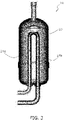
- FIG. 2A is a longitudinal sectional view of an accumulator 10. Expressions such as “upper” and “lower” may be used to describe the directions and arrangements of the accumulator 10 below and, unless otherwise specified, the expressions such as “upper” and “lower” are used with reference to FIG. 2 .
- the accumulator 10 is a device that separates a refrigerant in a gas-liquid two-phase state into a gas refrigerant and a liquid refrigerant in a refrigeration apparatus including a refrigeration cycle in which the refrigerant is circulated. As illustrated in FIG. 1 , the accumulator 10 is arranged on the inlet side of a compressor 30 including a first compression unit 31a and a second compression unit 31b in an outdoor unit of an air-conditioning apparatus as a refrigeration apparatus. The accumulator 10 forms part of a refrigerant circuit of the air-conditioning apparatus. Solid arrows indicate the flow of the refrigerant in the refrigeration cycle.
- the compressor 30 is what is called a twin rotary compressor, primarily including the first compression unit 31a, the second compression unit 31b, a first inlet pipe 32a, a second inlet pipe 32b, a first cylinder 33a, a second cylinder 33b, a first piston 34a, a second piston 34b, a casing 35, a motor 36, a discharge pipe 37, and a crankshaft 38.
- the refrigerants flowing from a first outlet pipe 14a and a second outlet pipe 14b of the accumulator 10 are suctioned into the first compression unit 31a and the second compression unit 31b through the first inlet pipe 32a and the second inlet pipe 32b.
- the first cylinder 33a and the first piston 34a constitute the first compression unit 31a.
- the second cylinder 33b and the second piston 34b constitute the second compression unit 31b.
- the refrigerants filled in the gap between the first cylinder 33a and the first piston 34a and in the gap between the second cylinder 33b and the second piston 34b are compressed.
- the compressed refrigerant flows upward in an internal space of the casing 35 and is discharged through the discharge pipe 37.
- the accumulator 10 primarily includes a main body casing 15, the first outlet pipe 14a, the second outlet pipe 14b, and a coupling portion 13.
- the main body casing 15 includes an upper body portion 16 and a lower body portion 18.
- an inlet pipe 11 is a pipe penetrating through an upper surface of the upper body portion 16.
- An end portion of the inlet pipe 11 in the internal space of the accumulator 10 has an opening facing downward.
- An end portion of the inlet pipe 11 outside the accumulator 10 is coupled to the refrigerant circuit.
- the refrigerant passing through the inlet pipe 11 and flowing into the internal space of the main body casing 15 is a refrigerant in a gas-liquid two-phase state.
- the baffle 12 is a member that prevents the liquid refrigerant included in the refrigerant in a gas-liquid two-phase state from flowing into the first outlet pipe 14a and the second outlet pipe 14b.
- the accumulator 10 prevents the liquid refrigerant from being suctioned into the first compression unit 31a and the second compression unit 31b of the compressor 30.
- the refrigerant in a gas-liquid two-phase state flows into the internal space of the main body casing 15 through the inlet pipe 11 and then collides with the baffle 12.
- the liquid refrigerant included in a gas-liquid two-phase state adheres to the surface of the baffle 12.
- the liquid refrigerant adhering to the baffle 12 flows on the surface of the baffle 12 toward an outer edge portion, falls down in the internal space of the main body casing 15, and is stored in a bottom portion of the main body casing 15.
- the gas refrigerant included in the refrigerant in a gas-liquid two-phase state flows into the first outlet pipe 14a and the second outlet pipe 14b via the coupling portion 13 in the internal space of the main body casing 15.
- the first outlet pipe 14a and the second outlet pipe 14b are pipes penetrating through a lower surface of the lower body portion 18 from the main body casing 15 and extending toward the first compression unit 31a and the second compression unit 31b.
- the first outlet pipe 14a includes an upper end 14a1, a vertical portion 14a2, a curved portion 14a3, and a horizontal portion 14a4.
- the second outlet pipe 14b includes an upper end 14b1, a vertical portion 14b2, a curved portion 14b3, and a horizontal portion 14b4.
- the first outlet pipe 14a and the second outlet pipe 14b are coupled to a joining portion 13a of the coupling portion 13 at the upper end 14a1 and the upper end 14b1, respectively.
- the first outlet pipe 14a and the second outlet pipe 14b are coupled to the first inlet pipe 32a and the second inlet pipe 32b of the compressor 30 at the left ends of the horizontal portion 14a4 and the horizontal portion 14b4, respectively.
- the first outlet pipe 14a and the second outlet pipe 14b are preferably general-purpose circular pipes.
- the refrigerant flowing into the first outlet pipe 14a and the second outlet pipe 14b is suctioned into the first compression unit 31a and the second compression unit 31b of the compressor 30.
- the refrigerant may flow backward from the compressor 30.
- the refrigerant flows upward through the first outlet pipe 14a and the second outlet pipe 14b. Dashed arrows in FIG. 2A indicate the flow of the refrigerant flowing backward.
- the coupling portion 13 is coupled to the upper end 14a1 of the first outlet pipe 14a and the upper end 14b1 of the second outlet pipe 14b in the main body casing 15.
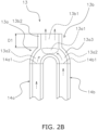
- the coupling portion 13 includes the joining portion 13a and an extension portion 13b.
- the coupling portion 13 may be a T-shaped joint or a Y-shaped joint instead of the member having the shape illustrated in FIG. 2A .
- the joining portion 13a is a portion that joins the refrigerants flowing upward through the first outlet pipe 14a and the second outlet pipe 14b.
- the joining portion 13a includes a joining space 13a1, a pre-joining space 13a2, and a space forming portion 13a3.
- the space forming portion 13a3 forms the joining space 13a1 and the pre-joining space 13a2.
- the refrigerants flowing upward through the first outlet pipe 14a and the second outlet pipe 14b pass through the respective pre-joining spaces 13a2 and join in the joining space 13a1.
- the extension portion 13b has a tubular shape extending upward from the joining portion 13a.
- the extension portion 13b includes a flow straightening space 13b1 and a space forming portion 13b2.
- the space forming portion 13b2 forms the flow straightening space 13b1.
- the refrigerant After flowing upward through the first outlet pipe 14a and the second outlet pipe 14b and joining in the joining space 13a1, the refrigerant is straightened in the process of passing through the flow straightening space 13b1.
- first outlet pipe 14a and the second outlet pipe 14b are circular pipes, and a height dimension D1 of the extension portion 13b is greater than the inner diameter of the first outlet pipe 14a and greater than the inner diameter of the second outlet pipe 14b.
- an outlet pipe of an accumulator 20 for a conventional twin rotary compressor has an inverted U-shape.
- the outlet pipe is bent at an upper portion.
- a first outlet pipe 24a and a second outlet pipe 24b, which are two lower portions of the outlet pipe, are coupled to the first inlet pipe 32a and the second inlet pipe 32b, respectively, of the compressor 30.
- the upper portion of the outlet pipe is cut at the bent portion housed in the internal space of the accumulator 20 in order to suction the refrigerant.
- the refrigerant flowing backward from the compressor 30 flows upward through the first outlet pipe 24a and the second outlet pipe 24b and is discharged from a corresponding cut portion 23.
- the timings in which the refrigerants flowing upward through the first outlet pipe 24a and the second outlet pipe 24b reach the cut portion 23 are different in the first outlet pipe 24a and the second outlet pipe 24b. Therefore, as indicated in the dashed arrows in FIG. 3 , the refrigerant is discharged obliquely upward from the cut portion 21. As a result, an acoustic mode in the circumferential direction of the accumulator 20 is excited, and the accumulator 20 is largely vibrated in the radial direction.
- the radial direction is a direction connecting the centers of the compressor 30 and the accumulator 20 in planar view.
- the accumulator 10 As illustrated in FIG. 2B , even when the timings in which the refrigerants flowing upward through the first outlet pipe 14a and the second outlet pipe 14b reach the joining space 13a1 of the joining portion 13a are different, the refrigerant is straightened in the flow straightening space 13b1 of the extension portion 13b. Therefore, as indicated in the dashed arrows in FIG. 2B , the refrigerant discharged from the upper end of the extension portion 13b flows substantially upward. As a result, the acoustic mode in the circumferential direction of the accumulator 10 is hardly excited, and the accumulator 10 is not largely vibrated in the radial direction.
- the first outlet pipe 14a and the second outlet pipe 14b of the accumulator 10 are circular pipes. Further, the height dimension D1 of the extension portion 13b is greater than the inner diameter of the first outlet pipe 14a and greater than the inner diameter of the second outlet pipe 14b. Accordingly, the height dimension D1 of the extension portion 13b is ensured to some extent. As a result, the refrigerants flowing upward through the first outlet pipe 14a and the second outlet pipe 14b are further straightened in the flow straightening space 13b1 of the extension portion 13b.
- a general-purpose T-shaped joint or Y-shaped joint may be used for the coupling portion 13 of the accumulator 10.
- a general-purpose component may be used for the coupling portion 13, which may reduce the cost of the accumulator 10.
- the acceleration level and the noise level of the accumulator 10 according to the present embodiment and the conventional accumulator 20 are compared.
- the difference between the accumulator 10 and the accumulator 20 is basically only the structure of the upper end portion of the outlet pipe.
- the dimensions of the accumulator 10 and the accumulator 20 used in this verification will be described with reference to FIG. 4 .
- the outlet pipes of the accumulator 10 and the accumulator 20 used in this verification are circular pipes.
- the accumulator 10 and the accumulator 20 having, at the minimum, a body outer diameter D2 of ⁇ 75, an outlet pipe outer diameter D3 of ⁇ 9.5, and an outlet pipes distance D4 of 21 mm were used.
- the accumulator 10 and the accumulator 20 having, at the maximum, the body outer diameter D2 of ⁇ 89.1, the outlet pipe outer diameter D3 of ⁇ 16, and the outlet pipes distance D4 of 33 mm were used.
- the coupling portion 13, the baffle 12, the cut portion 21, and the like are omitted from FIG. 4 .
- FIGS. 5A and 5B illustrate the distributions of the pressures acting on the accumulator 10 and the accumulator 20 due to the periodic back-flow of the refrigerant.
- the scales in FIGS. 5A and 5B indicate the values of the amplitude. Both pressure pulsations have a frequency of approximately 1630 Hz.
- FIG. 5A illustrates the distribution of the pressures acting on the accumulator 10.
- the amplitudes in the positive direction are concentrated at the upper portion and the lower portion of the accumulator 10.
- the amplitudes in the negative direction are concentrated at the central portion of the accumulator 10. Therefore, the accumulator 10 as a whole is not vibrated in the radial direction.
- FIG. 5B illustrates the distribution of the pressures acting on the accumulator 20.
- the amplitudes in the positive direction are concentrated at the upper left portion and the lower right portion of the accumulator 20.
- the amplitudes in the negative direction are concentrated in the upper right portion and the lower left portion of the accumulator 20. Therefore, the accumulator 20 as a whole is vibrated in the radial direction.
- the natural frequencies of the accumulators 10, 20 in the radial direction primarily depends on the weights of the accumulators 10, 20, the structure of the area where the accumulators 10, 20 are coupled to the compressor 30, and the structure of the area where the accumulators 10, 20 themselves are fixed.
- the difference between the accumulator 10 and the accumulator 20 is basically only the structure of the upper end portions of the two outlet pipes. As a result, the natural frequencies of the accumulator 10 and the accumulator 20 in the radial direction are substantially the same.
- the natural frequencies of the accumulator 10 and the accumulator 20 in the radial direction include approximately 1630 Hz.
- the periodic back-flow of the refrigerant causes a pressure pulsation in the circumferential direction at approximately 1630 Hz in the accumulator 20.
- the pressure pulsation of approximately 1630 Hz also occurs in the accumulator 10, it is not a pressure pulsation in the circumferential direction.
- the natural frequencies of the accumulator 10 and the accumulator 20 in the radial direction include approximately 1630 Hz.
- the accumulator 20 is largely vibrated and largely oscillates in the radial direction as the acoustic mode in the circumferential direction is excited.
- the accumulator 10 is not largely vibrated and does not largely oscillate in the radial direction as the acoustic mode in the circumferential direction is not excited.
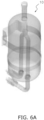
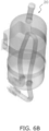
- FIGS. 6A and 6B illustrate the states of vibrations of the accumulator 10 and the accumulator 20 under the same condition. It is clearly understood that the oscillation of the conventional accumulator 20 illustrated in FIG. 6B is larger.
- FIG. 8 illustrates the acceleration levels of the accumulator 10 and the accumulator 20.
- the vertical axis is an acceleration level
- the horizontal axis is a frequency [Hz].
- the evaluation point for the acceleration level is a point P1 in the lower portion of the main body casing 15 on the opposite side of the compressor 30.
- FIG. 8 it is understood that, at approximately 1630 Hz, the acceleration peak level of the accumulator 10 is significantly reduced compared to the acceleration peak level of the accumulator 20.
- FIG. 9 illustrates the noise levels of the accumulator 10 and the accumulator 20.
- the vertical axis is a noise level [dB]
- the horizontal axis is a frequency [Hz].
- the evaluation point for the noise level is a point P2 away from the center in the height direction of the main body casing 15 by 30 cm in the direction opposite to the compressor 30.
- the noise peak level of the accumulator 10 is reduced by approximately 25 dB from the noise peak level of the accumulator 20.
- the position of the extension portion 13b of the accumulator 10 is not described in particular.
- the center of the extension portion 13b of the accumulator 10 is located on the inner side of a virtual circle CR illustrated in FIG. 10 .
- the virtual circle CR is a circle that has a center at a midpoint C3 of a first line LI that is the line connecting centers C1, C2 of the upper ends 14a1, 14b1 of the first outlet pipe 14a and the second outlet pipe 14b, respectively, in planar view, and that has a diameter that is the length of the first line LI.
- the refrigerant flowing backward and upward through the first outlet pipe 14a and the second outlet pipe 14b and discharged from the upper end of the extension portion 13b is discharged near the center axis of the accumulator 10.
- the accumulator 10 is less likely to be vibrated in the radial direction.
- the first outlet pipe 14a and the second outlet pipe 14b are arranged such that the center axis of the accumulator 10 matches the midpoint C3 of the first line LI.
- the midpoint C3 of the first line LI matches the center of the extension portion 13b. Accordingly, the refrigerant flowing backward and upward through the first outlet pipe 14a and the second outlet pipe 14b and discharged from the upper end of the extension portion 13b is discharged on the center axis of the accumulator 10.
- the accumulator 10 is further less likely to be vibrated in the radial direction.
- Patent Literature 1 Japanese Unexamined Patent Publication No. 2005-54741
Landscapes
- Engineering & Computer Science (AREA)
- Mechanical Engineering (AREA)
- General Engineering & Computer Science (AREA)
- Chemical & Material Sciences (AREA)
- Analytical Chemistry (AREA)
- Power Engineering (AREA)
- Physics & Mathematics (AREA)
- Thermal Sciences (AREA)
- Applications Or Details Of Rotary Compressors (AREA)
- Compressor (AREA)
Abstract
Description
- The present disclosure relates to an accumulator.
- Conventionally, as discussed in Patent Literature 1 (
Japanese Unexamined Patent Publication No. 2005-54741 - Typically, the refrigerant passing through the outlet pipe of the accumulator flows downward from an opening in the upper portion toward the compressor. However, in some state of the compressor and a refrigerant circuit, the refrigerant may flow backward through the two outlet pipes from the compressor. At this point, the refrigerant flows upward through the two lower portions of the outlet pipes, joins at the upper portion of the outlet pipes, and is discharged from the cut opening into the internal space of the accumulator. This discharged refrigerant causes the issue of large vibrations of the accumulator.
- An accumulator according to a first aspect is an accumulator arranged on an inlet side of a rotary compressor including a first compression unit and a second compression unit. The accumulator includes a main body casing, a first outlet pipe, a second outlet pipe, and a coupling portion. The main body casing includes an upper body portion and a lower body portion. The first outlet pipe and the second outlet pipe penetrate through the lower body portion from the main body casing and extend toward the first compression unit and the second compression unit, respectively. The coupling portion is coupled to an upper end of the first outlet pipe and an upper end of the second outlet pipe in the main body casing. The coupling portion is provided with a joining portion and an extension portion. The joining portion joins refrigerants flowing upward through the first outlet pipe and the second outlet pipe. The extension portion has a tubular shape extending upward from the joining portion.
- In the accumulator according to the first aspect, even in the case of occurrence of the phenomenon where the refrigerants flow upward through the first outlet pipe and the second outlet pipe, the refrigerants join at the joining portion, pass through the extension portion, and are discharged from the upper end of the extension portion into the internal space of the accumulator. Therefore, the refrigerant is straightened in the process of passing through the extension portion. As a result, the accumulator is not largely vibrated.
- The accumulator according to a second aspect is the accumulator according to the first aspect, and each of the first outlet pipe and the second outlet pipe is a circular pipe. A height dimension of the extension portion is greater than an inner diameter of the first outlet pipe and greater than an inner diameter of the second outlet pipe.
- In the accumulator according to the second aspect, the height dimension of the extension portion is greater than the inner diameter of the first outlet pipe and greater than the inner diameter of the second outlet pipe. Accordingly, the height dimension of the extension portion is ensured to some extent. As a result, the refrigerants flowing upward through the first outlet pipe and the second outlet pipe are further straightened in the extension portion.
- The accumulator according to a third aspect is the accumulator according to the first aspect or the second aspect, and the coupling portion is a T-shaped joint or a Y-shaped joint.
- In the accumulator according to the third aspect, the coupling portion is a T-shaped joint or a Y-shaped joint. Thus, a general-purpose component may be used for the coupling portion.
- The accumulator according to a fourth aspect is the accumulator according to any of the first aspect to the third aspect, and a center of the extension portion is located on an inner side of a virtual circle. The virtual circle has a center at a midpoint of a first line that is a line connecting centers of the upper ends of the first outlet pipe and the second outlet pipe, respectively, in planar view and has a diameter that is a length of the first line.
- In the accumulator according to the fourth aspect, the center of the extension portion is located on the inner side of the virtual circle. Accordingly, the refrigerants flowing backward and upward through the first outlet pipe and the second outlet pipe and discharged from the upper end of the extension portion are discharged near the center axis of the accumulator. As a result, the accumulator is further less likely to be vibrated.
- The accumulator according to a fifth aspect is the accumulator according to the fourth aspect, and the midpoint of the first line matches the center of the extension portion.
- In the accumulator according to the fifth aspect, the midpoint of the first line matches the center of the extension portion. Accordingly, the refrigerants flowing backward and upward through the first outlet pipe and the second outlet pipe and discharged from the upper end of the extension portion are discharged on the center axis of the accumulator. As a result, the accumulator is further less likely to be vibrated.
-
-
FIG. 1 is a cross-sectional view of an accumulator and a compressor. -
FIG. 2A is a longitudinal sectional view of the accumulator. -
FIG. 2B is a longitudinal sectional view of the vicinity of a coupling portion of the accumulator. -
FIG. 3 is a longitudinal sectional view of a conventional accumulator. -
FIG. 4 is a diagram illustrating dimensions of the accumulator and the conventional accumulator. -
FIG. 5A is a diagram illustrating the distribution of pressures acting on the accumulator. -
FIG. 5B is a diagram illustrating the distribution of pressures acting on the conventional accumulator. -
FIG. 6A is a diagram illustrating the state of vibration of the accumulator. -
FIG. 6B is a diagram illustrating the state of vibration of the conventional accumulator. -
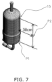
FIG. 7 is a diagram illustrating evaluation points to verify the effect of the present disclosure. -
FIG. 8 is a graph illustrating acceleration levels of the accumulator and the conventional accumulator. -
FIG. 9 is a graph illustrating noise levels of the accumulator and the conventional accumulator. -
FIG. 10 is a top view and a cross-sectional view of an extension portion of the accumulator. -
FIG. 2A is a longitudinal sectional view of anaccumulator 10. Expressions such as "upper" and "lower" may be used to describe the directions and arrangements of theaccumulator 10 below and, unless otherwise specified, the expressions such as "upper" and "lower" are used with reference toFIG. 2 . - The
accumulator 10 is a device that separates a refrigerant in a gas-liquid two-phase state into a gas refrigerant and a liquid refrigerant in a refrigeration apparatus including a refrigeration cycle in which the refrigerant is circulated. As illustrated inFIG. 1 , theaccumulator 10 is arranged on the inlet side of acompressor 30 including afirst compression unit 31a and asecond compression unit 31b in an outdoor unit of an air-conditioning apparatus as a refrigeration apparatus. Theaccumulator 10 forms part of a refrigerant circuit of the air-conditioning apparatus. Solid arrows indicate the flow of the refrigerant in the refrigeration cycle. - The
compressor 30 is what is called a twin rotary compressor, primarily including thefirst compression unit 31a, thesecond compression unit 31b, afirst inlet pipe 32a, asecond inlet pipe 32b, afirst cylinder 33a, asecond cylinder 33b, afirst piston 34a, asecond piston 34b, acasing 35, amotor 36, adischarge pipe 37, and acrankshaft 38. - By the refrigeration cycle, the refrigerants flowing from a
first outlet pipe 14a and asecond outlet pipe 14b of theaccumulator 10 are suctioned into thefirst compression unit 31a and thesecond compression unit 31b through thefirst inlet pipe 32a and thesecond inlet pipe 32b. Thefirst cylinder 33a and thefirst piston 34a constitute thefirst compression unit 31a. Thesecond cylinder 33b and thesecond piston 34b constitute thesecond compression unit 31b. When themotor 36 is driven, thecrankshaft 38 rotates. When thecrankshaft 38 rotates, thefirst piston 34a and thesecond piston 34b make a rotary movement inside thefirst cylinder 33a and thesecond cylinder 33b. When thefirst piston 34a and thesecond piston 34b make a rotary movement, the refrigerants filled in the gap between thefirst cylinder 33a and thefirst piston 34a and in the gap between thesecond cylinder 33b and thesecond piston 34b are compressed. The compressed refrigerant flows upward in an internal space of thecasing 35 and is discharged through thedischarge pipe 37. - The
accumulator 10 primarily includes amain body casing 15, thefirst outlet pipe 14a, thesecond outlet pipe 14b, and acoupling portion 13. - As illustrated in
FIG. 2A , themain body casing 15 includes anupper body portion 16 and alower body portion 18. - As illustrated in
FIG. 2A , aninlet pipe 11 is a pipe penetrating through an upper surface of theupper body portion 16. An end portion of theinlet pipe 11 in the internal space of theaccumulator 10 has an opening facing downward. An end portion of theinlet pipe 11 outside theaccumulator 10 is coupled to the refrigerant circuit. - The refrigerant passing through the
inlet pipe 11 and flowing into the internal space of themain body casing 15 is a refrigerant in a gas-liquid two-phase state. As illustrated inFIG. 2A , thebaffle 12 is a member that prevents the liquid refrigerant included in the refrigerant in a gas-liquid two-phase state from flowing into thefirst outlet pipe 14a and thesecond outlet pipe 14b. Thus, theaccumulator 10 prevents the liquid refrigerant from being suctioned into thefirst compression unit 31a and thesecond compression unit 31b of thecompressor 30. - Specifically, the refrigerant in a gas-liquid two-phase state flows into the internal space of the main body casing 15 through the
inlet pipe 11 and then collides with thebaffle 12. The liquid refrigerant included in a gas-liquid two-phase state adheres to the surface of thebaffle 12. The liquid refrigerant adhering to thebaffle 12 flows on the surface of thebaffle 12 toward an outer edge portion, falls down in the internal space of themain body casing 15, and is stored in a bottom portion of themain body casing 15. Conversely, the gas refrigerant included in the refrigerant in a gas-liquid two-phase state flows into thefirst outlet pipe 14a and thesecond outlet pipe 14b via thecoupling portion 13 in the internal space of themain body casing 15. - As illustrated in
FIG. 2A , thefirst outlet pipe 14a and thesecond outlet pipe 14b are pipes penetrating through a lower surface of thelower body portion 18 from themain body casing 15 and extending toward thefirst compression unit 31a and thesecond compression unit 31b. - The
first outlet pipe 14a includes an upper end 14a1, a vertical portion 14a2, a curved portion 14a3, and a horizontal portion 14a4. Thesecond outlet pipe 14b includes an upper end 14b1, a vertical portion 14b2, a curved portion 14b3, and a horizontal portion 14b4. Thefirst outlet pipe 14a and thesecond outlet pipe 14b are coupled to a joiningportion 13a of thecoupling portion 13 at the upper end 14a1 and the upper end 14b1, respectively. Further, thefirst outlet pipe 14a and thesecond outlet pipe 14b are coupled to thefirst inlet pipe 32a and thesecond inlet pipe 32b of thecompressor 30 at the left ends of the horizontal portion 14a4 and the horizontal portion 14b4, respectively. - The
first outlet pipe 14a and thesecond outlet pipe 14b are preferably general-purpose circular pipes. - In the refrigeration cycle, the refrigerant flowing into the
first outlet pipe 14a and thesecond outlet pipe 14b is suctioned into thefirst compression unit 31a and thesecond compression unit 31b of thecompressor 30. However, in some state of thecompressor 30 and the refrigerant circuit, the refrigerant may flow backward from thecompressor 30. At this point, the refrigerant flows upward through thefirst outlet pipe 14a and thesecond outlet pipe 14b. Dashed arrows inFIG. 2A indicate the flow of the refrigerant flowing backward. - As illustrated in
FIG. 2A , thecoupling portion 13 is coupled to the upper end 14a1 of thefirst outlet pipe 14a and the upper end 14b1 of thesecond outlet pipe 14b in themain body casing 15. Thecoupling portion 13 includes the joiningportion 13a and anextension portion 13b. - The
coupling portion 13 may be a T-shaped joint or a Y-shaped joint instead of the member having the shape illustrated inFIG. 2A . - As illustrated in
FIG. 2A , the joiningportion 13a is a portion that joins the refrigerants flowing upward through thefirst outlet pipe 14a and thesecond outlet pipe 14b. - As illustrated in
FIG. 2B , the joiningportion 13a includes a joining space 13a1, a pre-joining space 13a2, and a space forming portion 13a3. The space forming portion 13a3 forms the joining space 13a1 and the pre-joining space 13a2. - The refrigerants flowing upward through the
first outlet pipe 14a and thesecond outlet pipe 14b pass through the respective pre-joining spaces 13a2 and join in the joining space 13a1. - As illustrated in
FIG. 2A , theextension portion 13b has a tubular shape extending upward from the joiningportion 13a. - As illustrated in
FIG. 2B , theextension portion 13b includes a flow straightening space 13b1 and a space forming portion 13b2. The space forming portion 13b2 forms the flow straightening space 13b1. - After flowing upward through the
first outlet pipe 14a and thesecond outlet pipe 14b and joining in the joining space 13a1, the refrigerant is straightened in the process of passing through the flow straightening space 13b1. - Here, the
first outlet pipe 14a and thesecond outlet pipe 14b are circular pipes, and a height dimension D1 of theextension portion 13b is greater than the inner diameter of thefirst outlet pipe 14a and greater than the inner diameter of thesecond outlet pipe 14b. - (3-1)
As illustrated inFIG. 3 , an outlet pipe of anaccumulator 20 for a conventional twin rotary compressor has an inverted U-shape. The outlet pipe is bent at an upper portion. Afirst outlet pipe 24a and asecond outlet pipe 24b, which are two lower portions of the outlet pipe, are coupled to thefirst inlet pipe 32a and thesecond inlet pipe 32b, respectively, of thecompressor 30. The upper portion of the outlet pipe is cut at the bent portion housed in the internal space of theaccumulator 20 in order to suction the refrigerant. The refrigerant flowing backward from thecompressor 30 flows upward through thefirst outlet pipe 24a and thesecond outlet pipe 24b and is discharged from acorresponding cut portion 23. - The timings in which the refrigerants flowing upward through the
first outlet pipe 24a and thesecond outlet pipe 24b reach thecut portion 23 are different in thefirst outlet pipe 24a and thesecond outlet pipe 24b. Therefore, as indicated in the dashed arrows inFIG. 3 , the refrigerant is discharged obliquely upward from the cut portion 21. As a result, an acoustic mode in the circumferential direction of theaccumulator 20 is excited, and theaccumulator 20 is largely vibrated in the radial direction. Here, the radial direction is a direction connecting the centers of thecompressor 30 and theaccumulator 20 in planar view. - In the
accumulator 10 according to the present embodiment, as illustrated inFIG. 2B , even when the timings in which the refrigerants flowing upward through thefirst outlet pipe 14a and thesecond outlet pipe 14b reach the joining space 13a1 of the joiningportion 13a are different, the refrigerant is straightened in the flow straightening space 13b1 of theextension portion 13b. Therefore, as indicated in the dashed arrows inFIG. 2B , the refrigerant discharged from the upper end of theextension portion 13b flows substantially upward. As a result, the acoustic mode in the circumferential direction of theaccumulator 10 is hardly excited, and theaccumulator 10 is not largely vibrated in the radial direction. - (3-2)
Thefirst outlet pipe 14a and thesecond outlet pipe 14b of theaccumulator 10 are circular pipes. Further, the height dimension D1 of theextension portion 13b is greater than the inner diameter of thefirst outlet pipe 14a and greater than the inner diameter of thesecond outlet pipe 14b. Accordingly, the height dimension D1 of theextension portion 13b is ensured to some extent. As a result, the refrigerants flowing upward through thefirst outlet pipe 14a and thesecond outlet pipe 14b are further straightened in the flow straightening space 13b1 of theextension portion 13b. - (3-3)
Instead of the member having the shape illustrated inFIG. 2A , a general-purpose T-shaped joint or Y-shaped joint may be used for thecoupling portion 13 of theaccumulator 10. Thus, a general-purpose component may be used for thecoupling portion 13, which may reduce the cost of theaccumulator 10. - In this verification, the acceleration level and the noise level of the
accumulator 10 according to the present embodiment and theconventional accumulator 20 are compared. The difference between theaccumulator 10 and theaccumulator 20 is basically only the structure of the upper end portion of the outlet pipe. - The dimensions of the
accumulator 10 and theaccumulator 20 used in this verification will be described with reference toFIG. 4 . The outlet pipes of theaccumulator 10 and theaccumulator 20 used in this verification are circular pipes. In this verification, theaccumulator 10 and theaccumulator 20 having, at the minimum, a body outer diameter D2 of Φ75, an outlet pipe outer diameter D3 of Φ9.5, and an outlet pipes distance D4 of 21 mm were used. Furthermore, theaccumulator 10 and theaccumulator 20 having, at the maximum, the body outer diameter D2 of Φ89.1, the outlet pipe outer diameter D3 of Φ16, and the outlet pipes distance D4 of 33 mm were used. Further, thecoupling portion 13, thebaffle 12, the cut portion 21, and the like, are omitted fromFIG. 4 . -
FIGS. 5A and5B illustrate the distributions of the pressures acting on theaccumulator 10 and theaccumulator 20 due to the periodic back-flow of the refrigerant. The scales inFIGS. 5A and5B indicate the values of the amplitude. Both pressure pulsations have a frequency of approximately 1630 Hz. -
FIG. 5A illustrates the distribution of the pressures acting on theaccumulator 10. The amplitudes in the positive direction are concentrated at the upper portion and the lower portion of theaccumulator 10. Conversely, the amplitudes in the negative direction are concentrated at the central portion of theaccumulator 10. Therefore, theaccumulator 10 as a whole is not vibrated in the radial direction. -
FIG. 5B illustrates the distribution of the pressures acting on theaccumulator 20. The amplitudes in the positive direction are concentrated at the upper left portion and the lower right portion of theaccumulator 20. Conversely, the amplitudes in the negative direction are concentrated in the upper right portion and the lower left portion of theaccumulator 20. Therefore, theaccumulator 20 as a whole is vibrated in the radial direction. - The natural frequencies of the
accumulators accumulators accumulators compressor 30, and the structure of the area where theaccumulators accumulator 10 and theaccumulator 20 is basically only the structure of the upper end portions of the two outlet pipes. As a result, the natural frequencies of theaccumulator 10 and theaccumulator 20 in the radial direction are substantially the same. - As a result of verification, it has been found that the natural frequencies of the
accumulator 10 and theaccumulator 20 in the radial direction include approximately 1630 Hz. - As described in (4-2), the periodic back-flow of the refrigerant causes a pressure pulsation in the circumferential direction at approximately 1630 Hz in the
accumulator 20. Although the pressure pulsation of approximately 1630 Hz also occurs in theaccumulator 10, it is not a pressure pulsation in the circumferential direction. - Conversely, as described in (4-3), the natural frequencies of the
accumulator 10 and theaccumulator 20 in the radial direction include approximately 1630 Hz. - As a result, the
accumulator 20 is largely vibrated and largely oscillates in the radial direction as the acoustic mode in the circumferential direction is excited. Conversely, theaccumulator 10 is not largely vibrated and does not largely oscillate in the radial direction as the acoustic mode in the circumferential direction is not excited. -
FIGS. 6A and6B illustrate the states of vibrations of theaccumulator 10 and theaccumulator 20 under the same condition. It is clearly understood that the oscillation of theconventional accumulator 20 illustrated inFIG. 6B is larger. -
FIG. 8 illustrates the acceleration levels of theaccumulator 10 and theaccumulator 20. The vertical axis is an acceleration level, and the horizontal axis is a frequency [Hz]. As illustrated inFIG. 7 , the evaluation point for the acceleration level is a point P1 in the lower portion of the main body casing 15 on the opposite side of thecompressor 30. As illustrated inFIG. 8 , it is understood that, at approximately 1630 Hz, the acceleration peak level of theaccumulator 10 is significantly reduced compared to the acceleration peak level of theaccumulator 20. -
FIG. 9 illustrates the noise levels of theaccumulator 10 and theaccumulator 20. The vertical axis is a noise level [dB], and the horizontal axis is a frequency [Hz]. As illustrated inFIG. 7 , the evaluation point for the noise level is a point P2 away from the center in the height direction of the main body casing 15 by 30 cm in the direction opposite to thecompressor 30. As illustrated inFIG. 9 , it is understood that, at approximately 1630 Hz, the noise peak level of theaccumulator 10 is reduced by approximately 25 dB from the noise peak level of theaccumulator 20. - According to the present embodiment, the position of the
extension portion 13b of theaccumulator 10 is not described in particular. However, it is preferable that the center of theextension portion 13b of theaccumulator 10 is located on the inner side of a virtual circle CR illustrated inFIG. 10 . Here, the virtual circle CR is a circle that has a center at a midpoint C3 of a first line LI that is the line connecting centers C1, C2 of the upper ends 14a1, 14b1 of thefirst outlet pipe 14a and thesecond outlet pipe 14b, respectively, in planar view, and that has a diameter that is the length of the first line LI. - Accordingly, the refrigerant flowing backward and upward through the
first outlet pipe 14a and thesecond outlet pipe 14b and discharged from the upper end of theextension portion 13b is discharged near the center axis of theaccumulator 10. As a result, theaccumulator 10 is less likely to be vibrated in the radial direction. - Furthermore, here, the
first outlet pipe 14a and thesecond outlet pipe 14b are arranged such that the center axis of theaccumulator 10 matches the midpoint C3 of the first line LI. In other words, the midpoint C3 of the first line LI matches the center of theextension portion 13b. Accordingly, the refrigerant flowing backward and upward through thefirst outlet pipe 14a and thesecond outlet pipe 14b and discharged from the upper end of theextension portion 13b is discharged on the center axis of theaccumulator 10. As a result, theaccumulator 10 is further less likely to be vibrated in the radial direction. - (5-2)
Although the embodiment of the present disclosure has been described above, it is understood that various changes may be made to forms and details without departing from the spirit and scope of the present disclosure described in claims. -
- 10
- Accumulator
- 13
- Coupling portion
- 13a
- Joining portion
- 13b
- Extension portion
- 14a
- First outlet pipe
- 14b
- Second outlet pipe
- 15
- Main body casing
- 16
- Upper body portion
- 18
- Lower body portion
- 30
- Compressor
- 31a
- First compression unit
- 31b
- Second compression unit
- D1
- Height dimension of extension portion
- [Patent Literature 1]
Japanese Unexamined Patent Publication No. 2005-54741
Claims (5)
- An accumulator (10) arranged on an inlet side of a rotary compressor (30) including a first compression unit (31a) and a second compression unit (31b), the accumulator (10) comprising:a main body casing (15) including an upper body portion (16) and a lower body portion (18);a first outlet pipe (14a) and a second outlet pipe (14b) penetrating through the lower body portion from the main body casing and extending toward the first compression unit and the second compression unit, respectively; anda coupling portion (13) coupled to an upper end (14a1) of the first outlet pipe and an upper end (14b1) of the second outlet pipe in the main body casing, whereinthe coupling portion is provided with a joining portion (13a) that joins refrigerants flowing through the first outlet pipe and the second outlet pipe and a tubular extension portion (13b) extending upward from the joining portion.
- The accumulator (10) according to claim 1, whereineach of the first outlet pipe and the second outlet pipe is a circular pipe, anda height dimension (D1) of the extension portion is greater than an inner diameter of the first outlet pipe and greater than an inner diameter of the second outlet pipe.
- The accumulator (10) according to claim 1 or 2, wherein
the coupling portion is a T-shaped joint or a Y-shaped joint. - The accumulator (10) according to any of claims 1 to 3, whereina center of the extension portion is located on an inner side of a virtual circle (CR), andthe virtual circle has a center at a midpoint (C3) of a first line (LI) that is a line connecting centers (C1, C2) of the upper ends of the first outlet pipe and the second outlet pipe, respectively, in planar view and has a diameter that is a length of the first line.
- The accumulator (10) according to claim 4, wherein
the midpoint of the first line matches the center of the extension portion.
Applications Claiming Priority (2)
| Application Number | Priority Date | Filing Date | Title |
|---|---|---|---|
| JP2020056169A JP7244170B2 (en) | 2020-03-26 | 2020-03-26 | accumulator |
| PCT/JP2021/012627 WO2021193840A1 (en) | 2020-03-26 | 2021-03-25 | Accumulator |
Publications (2)
| Publication Number | Publication Date |
|---|---|
| EP4130479A1 true EP4130479A1 (en) | 2023-02-08 |
| EP4130479A4 EP4130479A4 (en) | 2023-08-23 |
Family
ID=77891873
Family Applications (1)
| Application Number | Title | Priority Date | Filing Date |
|---|---|---|---|
| EP21776677.3A Withdrawn EP4130479A4 (en) | 2020-03-26 | 2021-03-25 | ACCUMULATOR |
Country Status (3)
| Country | Link |
|---|---|
| EP (1) | EP4130479A4 (en) |
| JP (1) | JP7244170B2 (en) |
| WO (1) | WO2021193840A1 (en) |
Families Citing this family (1)
| Publication number | Priority date | Publication date | Assignee | Title |
|---|---|---|---|---|
| JP7842345B2 (en) * | 2022-04-27 | 2026-04-08 | ダイキン工業株式会社 | Rotary compressors and refrigeration systems |
Family Cites Families (6)
| Publication number | Priority date | Publication date | Assignee | Title |
|---|---|---|---|---|
| JPH0267473A (en) * | 1988-08-31 | 1990-03-07 | Toshiba Corp | Compressor |
| JP3064545B2 (en) * | 1991-08-30 | 2000-07-12 | 松下電器産業株式会社 | 2-cylinder rotary compressor |
| JP2005054741A (en) | 2003-08-07 | 2005-03-03 | Matsushita Electric Ind Co Ltd | Accumulator for multi-cylinder compressor |
| KR200382995Y1 (en) | 2005-01-26 | 2005-04-28 | 엘지전자 주식회사 | Accmulator for twin rotary compressor |
| WO2019142408A1 (en) | 2018-01-18 | 2019-07-25 | 東芝キヤリア株式会社 | Compressor and refrigeration cycle device |
| JP6978336B2 (en) | 2018-02-06 | 2021-12-08 | 東芝キヤリア株式会社 | Refrigeration cycle device using a multi-cylinder rotary compressor and a multi-cylinder rotary compressor |
-
2020
- 2020-03-26 JP JP2020056169A patent/JP7244170B2/en active Active
-
2021
- 2021-03-25 EP EP21776677.3A patent/EP4130479A4/en not_active Withdrawn
- 2021-03-25 WO PCT/JP2021/012627 patent/WO2021193840A1/en not_active Ceased
Also Published As
| Publication number | Publication date |
|---|---|
| EP4130479A4 (en) | 2023-08-23 |
| WO2021193840A1 (en) | 2021-09-30 |
| JP2021156197A (en) | 2021-10-07 |
| JP7244170B2 (en) | 2023-03-22 |
Similar Documents
| Publication | Publication Date | Title |
|---|---|---|
| EP3879208B1 (en) | Gas-liquid separator, compressor assembly and air conditioner | |
| US5205719A (en) | Refrigerant compressor discharge muffler | |
| CN100353057C (en) | Hermetic compressors and refrigeration and air conditioning systems | |
| JP6645845B2 (en) | Accumulator and compressor with multiple pipes | |
| JP2025508404A (en) | Fixing plate and reservoir | |
| KR100252593B1 (en) | Refrigerator compressor | |
| US7922460B2 (en) | Refrigerating compressor | |
| JP4232235B2 (en) | Scarf | |
| US7494328B2 (en) | NVH and gas pulsation reduction in AC compressor | |
| JP7244170B2 (en) | accumulator | |
| CN114777362B (en) | Knockout, compressor and air conditioner | |
| CN202101480U (en) | Liquid receiver for compressor | |
| US7740456B2 (en) | Suction silencer and compressor therewith | |
| JP2014077410A (en) | Compressor | |
| CN219509821U (en) | Compressor and refrigeration equipment | |
| CN217761266U (en) | Liquid storage device with cavity modal noise elimination function and air-conditioning compressor | |
| JPS6039517Y2 (en) | Silencer for hermetic compressor | |
| US7744357B2 (en) | Scroll compressor | |
| EP1653160A1 (en) | Outdoor unit for air conditioner | |
| JPH0526444Y2 (en) | ||
| CN222276878U (en) | A filter bottle for reducing noise | |
| CN114152005B (en) | Reinforcement plates, reservoirs and compressors | |
| CN223975219U (en) | Exhaust buffer cavity baffle for reducing noise of compressor in exhaust coil | |
| CN112709701B (en) | Compressor assembly and equipment having the same | |
| JP2892719B2 (en) | Hermetic electric compressor |
Legal Events
| Date | Code | Title | Description |
|---|---|---|---|
| STAA | Information on the status of an ep patent application or granted ep patent |
Free format text: STATUS: THE INTERNATIONAL PUBLICATION HAS BEEN MADE |
|
| PUAI | Public reference made under article 153(3) epc to a published international application that has entered the european phase |
Free format text: ORIGINAL CODE: 0009012 |
|
| STAA | Information on the status of an ep patent application or granted ep patent |
Free format text: STATUS: REQUEST FOR EXAMINATION WAS MADE |
|
| 17P | Request for examination filed |
Effective date: 20221021 |
|
| AK | Designated contracting states |
Kind code of ref document: A1 Designated state(s): AL AT BE BG CH CY CZ DE DK EE ES FI FR GB GR HR HU IE IS IT LI LT LU LV MC MK MT NL NO PL PT RO RS SE SI SK SM TR |
|
| DAV | Request for validation of the european patent (deleted) | ||
| DAX | Request for extension of the european patent (deleted) | ||
| P01 | Opt-out of the competence of the unified patent court (upc) registered |
Effective date: 20230525 |
|
| A4 | Supplementary search report drawn up and despatched |
Effective date: 20230721 |
|
| RIC1 | Information provided on ipc code assigned before grant |
Ipc: F25B 43/00 20060101ALI20230717BHEP Ipc: F04C 29/12 20060101AFI20230717BHEP |
|
| STAA | Information on the status of an ep patent application or granted ep patent |
Free format text: STATUS: EXAMINATION IS IN PROGRESS |
|
| 17Q | First examination report despatched |
Effective date: 20240411 |
|
| STAA | Information on the status of an ep patent application or granted ep patent |
Free format text: STATUS: THE APPLICATION HAS BEEN WITHDRAWN |
|
| 18W | Application withdrawn |
Effective date: 20240702 |