EP4130457A1 - Egr estimation method for internal combustion engine, and egr estimation device for internal combustion engine - Google Patents
Egr estimation method for internal combustion engine, and egr estimation device for internal combustion engine Download PDFInfo
- Publication number
- EP4130457A1 EP4130457A1 EP20928985.9A EP20928985A EP4130457A1 EP 4130457 A1 EP4130457 A1 EP 4130457A1 EP 20928985 A EP20928985 A EP 20928985A EP 4130457 A1 EP4130457 A1 EP 4130457A1
- Authority
- EP
- European Patent Office
- Prior art keywords
- egr
- passage
- internal combustion
- combustion engine
- intake
- Prior art date
- Legal status (The legal status is an assumption and is not a legal conclusion. Google has not performed a legal analysis and makes no representation as to the accuracy of the status listed.)
- Withdrawn
Links
Images


Classifications
-
- F—MECHANICAL ENGINEERING; LIGHTING; HEATING; WEAPONS; BLASTING
- F02—COMBUSTION ENGINES; HOT-GAS OR COMBUSTION-PRODUCT ENGINE PLANTS
- F02D—CONTROLLING COMBUSTION ENGINES
- F02D41/00—Electrical control of supply of combustible mixture or its constituents
- F02D41/0025—Controlling engines characterised by use of non-liquid fuels, pluralities of fuels, or non-fuel substances added to the combustible mixtures
- F02D41/0047—Controlling exhaust gas recirculation [EGR]
- F02D41/0065—Specific aspects of external EGR control
- F02D41/0072—Estimating, calculating or determining the EGR rate, amount or flow
-
- F—MECHANICAL ENGINEERING; LIGHTING; HEATING; WEAPONS; BLASTING
- F02—COMBUSTION ENGINES; HOT-GAS OR COMBUSTION-PRODUCT ENGINE PLANTS
- F02D—CONTROLLING COMBUSTION ENGINES
- F02D41/00—Electrical control of supply of combustible mixture or its constituents
- F02D41/0025—Controlling engines characterised by use of non-liquid fuels, pluralities of fuels, or non-fuel substances added to the combustible mixtures
- F02D41/0047—Controlling exhaust gas recirculation [EGR]
- F02D41/005—Controlling exhaust gas recirculation [EGR] according to engine operating conditions
-
- F—MECHANICAL ENGINEERING; LIGHTING; HEATING; WEAPONS; BLASTING
- F02—COMBUSTION ENGINES; HOT-GAS OR COMBUSTION-PRODUCT ENGINE PLANTS
- F02D—CONTROLLING COMBUSTION ENGINES
- F02D41/00—Electrical control of supply of combustible mixture or its constituents
- F02D41/02—Circuit arrangements for generating control signals
- F02D41/04—Introducing corrections for particular operating conditions
- F02D41/12—Introducing corrections for particular operating conditions for deceleration
- F02D41/123—Introducing corrections for particular operating conditions for deceleration the fuel injection being cut-off
-
- F—MECHANICAL ENGINEERING; LIGHTING; HEATING; WEAPONS; BLASTING
- F02—COMBUSTION ENGINES; HOT-GAS OR COMBUSTION-PRODUCT ENGINE PLANTS
- F02M—SUPPLYING COMBUSTION ENGINES IN GENERAL WITH COMBUSTIBLE MIXTURES OR CONSTITUENTS THEREOF
- F02M26/00—Engine-pertinent apparatus for adding exhaust gases to combustion-air, main fuel or fuel-air mixture, e.g. by exhaust gas recirculation [EGR] systems
- F02M26/02—EGR systems specially adapted for supercharged engines
- F02M26/04—EGR systems specially adapted for supercharged engines with a single turbocharger
- F02M26/06—Low pressure loops, i.e. wherein recirculated exhaust gas is taken out from the exhaust downstream of the turbocharger turbine and reintroduced into the intake system upstream of the compressor
-
- F—MECHANICAL ENGINEERING; LIGHTING; HEATING; WEAPONS; BLASTING
- F02—COMBUSTION ENGINES; HOT-GAS OR COMBUSTION-PRODUCT ENGINE PLANTS
- F02M—SUPPLYING COMBUSTION ENGINES IN GENERAL WITH COMBUSTIBLE MIXTURES OR CONSTITUENTS THEREOF
- F02M26/00—Engine-pertinent apparatus for adding exhaust gases to combustion-air, main fuel or fuel-air mixture, e.g. by exhaust gas recirculation [EGR] systems
- F02M26/49—Detecting, diagnosing or indicating an abnormal function of the EGR system
-
- Y—GENERAL TAGGING OF NEW TECHNOLOGICAL DEVELOPMENTS; GENERAL TAGGING OF CROSS-SECTIONAL TECHNOLOGIES SPANNING OVER SEVERAL SECTIONS OF THE IPC; TECHNICAL SUBJECTS COVERED BY FORMER USPC CROSS-REFERENCE ART COLLECTIONS [XRACs] AND DIGESTS
- Y02—TECHNOLOGIES OR APPLICATIONS FOR MITIGATION OR ADAPTATION AGAINST CLIMATE CHANGE
- Y02T—CLIMATE CHANGE MITIGATION TECHNOLOGIES RELATED TO TRANSPORTATION
- Y02T10/00—Road transport of goods or passengers
- Y02T10/10—Internal combustion engine [ICE] based vehicles
- Y02T10/40—Engine management systems
Definitions
- the present invention relates to EGR estimation of an internal combustion engine.
- JP2016-211456A discloses a technique in which when an exhaust gas accumulation amount of exhaust gas leaked into a downstream EGR passage when an EGR valve is fully closed exceeds a predetermined threshold value, fresh air introduction control is performed to introduce fresh air into the downstream EGR passage.
- the present invention is made in view of such a problem, and an object of the present invention is to estimate a more accurate EGR rate when the fuel cut is started when the EGR valve is fully closed.
- An EGR estimation method for internal combustion engines is an EGR estimation method for an internal combustion engine that estimates an EGR rate in an intake and exhaust system of an internal combustion engine, the intake and exhaust system of an internal combustion engine including: an intake system including an intake passage that is connected to an internal combustion engine, an exhaust system including an exhaust passage that is connected to the internal combustion engine, and the intake and exhaust system being provided with an EGR device including an EGR passage that connects the intake passage and the exhaust passage and an EGR valve that is provided in the EGR passage, the EGR estimation method comprising: determining a gas replacement state by exhaust gas and fresh air in an upstream EGR passage, which is a portion of the EGR passage between the EGR valve and the exhaust passage, when fuel cut of the internal combustion engine is started and the EGR valve is fully closed; and estimating the EGR rate based on a result of the determination.
- an EGR estimation device for internal combustion engines corresponding to the above EGR estimation method for an internal combustion engine.
- FIG. 1 is a diagram showing a main part of a vehicle.
- the vehicle includes an internal combustion engine 1, an intake system 10, an exhaust system 20, a supercharger 30, an EGR device 40, and a controller 50.
- the intake system 10 includes an intake passage 11, an air cleaner 12, an air flow meter 13, an intake throttle valve 14, an intercooler 15, a throttle valve 16, a collector 17, a compressor 31, an intake bypass passage 18, and a recirculation valve 19.
- the intake passage 11 connects the air cleaner 12 and the internal combustion engine 1 and circulates intake air introduced into the internal combustion engine 1.
- the intake passage 11 is provided with the air cleaner 12, the air flow meter 13, the intake throttle valve 14, the compressor 31, the intercooler 15, the throttle valve 16, and the collector 17 in this order from an upstream side.
- the air cleaner 12 removes foreign matters contained in the intake air.
- the air flow meter 13 measures a flow rate of the intake air.
- the intake throttle valve 14 is provided in a portion of the intake passage 11, which is on an upstream side of an EGR convergence portion 11a to which an EGR passage 41 is connected, which will be described later.
- the intake throttle valve 14 increases a recirculation amount of exhaust gas through the EGR passage 41 by reducing an opening degree.
- the intercooler 15 cools the supercharged intake air.
- the throttle valve 16 adjusts an amount of the intake air introduced into the internal combustion engine 1.
- the collector 17 temporarily stores the intake air.
- the compressor 31 is a compressor of the supercharger 30 and compresses the intake air.
- the exhaust system 20 includes an exhaust passage 21, an upstream catalyst 22, a downstream catalyst 23, and a turbine 32.
- the exhaust passage 21 is connected to the internal combustion engine 1 and circulates exhaust gas discharged from the internal combustion engine 1.
- the exhaust passage 21 is provided with the turbine 32, the upstream catalyst 22, and the downstream catalyst 23 in this order from an upstream side.
- the upstream catalyst 22 and the downstream catalyst 23 purify the exhaust gas.
- the turbine 32 is the turbine of the supercharger 30 and recovers energy from the exhaust gas.
- the supercharger 30 compresses the intake air and then supplies to the internal combustion engine 1.
- the supercharger 30 is a turbocharger and includes the compressor 31, the turbine 32, and a shaft 33.
- the supercharger 30 is provided in the intake passage 11 and the exhaust passage 21 by providing the compressor 31 in the intake passage 11 and the turbine 32 in the exhaust passage 21.
- the compressor 31 is rotated via the shaft 33 to compress the intake air.
- a pair of compressor wheels arranged in a back-to-back direction are provided on the shaft 33, and the intake air is compressed by the pair of compressor wheels.
- the turbine 32 is provided with an exhaust bypass passage, and the exhaust bypass passage is provided with a waste gate valve (not shown) that adjusts a flow rate of the flowing exhaust gas.
- the EGR device 40 includes the EGR passage 41, an EGR cooler 42, and an EGR valve 43.
- the EGR device 40 recirculates the exhaust gas from the exhaust passage 21 to the intake passage 11.
- the EGR passage 41 connects the exhaust passage 21 and the intake passage 11.
- the EGR passage 41 recirculates a part of the exhaust gas flowing through the exhaust passage 21 to the intake passage 11 as EGR gas.
- the EGR passage 41 is provided with the EGR cooler 42 and the EGR valve 43.
- the EGR cooler 42 cools the EGR gas flowing through the EGR passage 41.
- the EGR valve 43 adjusts a flow rate of the EGR gas flowing through the EGR passage 41.
- the EGR valve 43 includes, for example, a butterfly valve.
- the EGR passage 41 includes an upstream EGR passage 41a, which is a portion between the EGR valve 43 and the exhaust passage 21, and a downstream EGR passage 41b, which is a portion between the EGR valve 43 and the intake passage 11. It can be understood that the upstream EGR passage 41a includes the EGR cooler 42.
- the EGR device 40 specifically, the EGR passage 41 connects a portion downstream of the supercharger 30, that is, the turbine 32 in the exhaust passage 21, and a portion upstream of the supercharger 30, that is, the compressor 31 in the intake passage 11.
- the EGR passage 41 connecting the intake passage 11 and the exhaust passage 21 forms an EGR path of a low pressure loop, that is, an LPL.
- the EGR passage 41 connects a portion of the exhaust passage 21 between the upstream catalyst 22 and the downstream catalyst 23 and a portion of the intake passage 11 between the intake throttle valve 14 and the compressor 31.
- the intake bypass passage 18 connects an upstream pressure portion and a downstream pressure portion of the supercharger 30 in the intake system 10.
- the upstream pressure portion is a portion of the intake passage 11 on an upstream side of the supercharger 30 and on a downstream side of the EGR convergence portion 11a.
- the downstream pressure portion is a portion of the intake passage 11 on a downstream side of the supercharger 30 and on an upstream side of the intercooler 15.
- Connecting to the downstream pressure portion of the supercharger 30 in the intake system 10 includes connecting to the compressor 31 so that the compressed intake air can flow into the intake bypass passage 18.
- the recirculation valve 19 is provided in the intake bypass passage 18.
- the recirculation valve 19 includes an on-off valve. During supercharging, a downstream pressure of the supercharger 30 is higher than an upstream pressure thereof. Therefore, when the recirculation valve 19 is opened during the supercharging, the intake air compressed by the compressor 31 is returned to the intake passage 11 on the portion upstream of the supercharger 30 via the intake bypass passage 18.
- the controller 50 is an electronic control device, and in addition to the air flow meter 13, signals from various sensors and switches such as a crank angle sensor 71 and an accelerator position sensor 72 are input to the controller 50.
- the crank angle sensor 71 generates a crank angle signal for each predetermined crank angle.
- the crank angle signal is used as a signal representing a rotation speed NE of the internal combustion engine 1.
- the accelerator position sensor 72 detects an amount of depression of an accelerator pedal of the vehicle. The amount of depression of the accelerator pedal is used as a signal representing a load of the internal combustion engine 1.
- the controller 50 controls the intake throttle valve 14, the throttle valve 16, the recirculation valve 19, and the EGR valve 43 in addition to the internal combustion engine 1 based on the above input signals from the various sensors and switches.
- the controller 50 controls the internal combustion engine 1 by controlling an ignition timing and a fuel injection amount according to an engine operating state.
- the engine operating state is, for example, the rotation speed NE or the load.
- FIGS. 2A to 2E are diagrams for explaining the flow mode of the gas.
- FIG. 2A shows a state during EGR operation.
- the exhaust gas is recirculated from the exhaust passage 21 to the intake passage 11. Therefore, as shown by hatching, the exhaust gas or the mixed gas of the exhaust gas and the intake gas flows through the exhaust passage 21, the EGR passage 41, and a portion of the intake passage 11 downstream of the EGR convergence portion 11a.
- FIG. 2B shows a state at a start of the fuel cut.
- the fuel cut is started when the EGR valve 43 is fully closed.
- the fresh air flows through the intake passage 11 and the exhaust passage 21.
- the exhaust gas is left in the EGR passage 41.
- FIG. 2C shows a state during the fuel cut.
- the exhaust gas leaks from the EGR valve 43 to the intake passage 11 side through the gap.
- the exhaust gas is replaced with the fresh air in the upstream EGR passage 41a, and in this case, finally, the entire EGR passage 41 is filled with the fresh air.
- FIG. 2D shows a state after the fuel injection is restarted and before the EGR valve 43 is opened.
- the fresh air flows through the intake passage 11 and the exhaust gas flows through the exhaust passage 21.
- the fresh air leaks through the gap of the EGR valve 43. Therefore, the exhaust gas is filled in the upstream EGR passage 41a by an amount of the fresh air leaking. The exhaust gas is gradually filled from an upstream portion of the upstream EGR passage 41a.
- FIG. 2E shows a state in which the upstream EGR passage 41a is filled with the exhaust gas after the EGR valve 43 is opened.
- the EGR valve 43 is opened, the fresh air remaining in the upstream EGR passage 41a first flows into the EGR valve 43, and then the exhaust gas flows into the EGR valve 43.
- the EGR rate in the EGR valve 43 remains zero.
- the EGR rate then begins to rise after the upstream EGR passage 41a is filled with the exhaust gas as shown in FIG. 4E.
- the EGR rate (actual EGR rate) in the EGR valve 43 is estimated as described below.
- FIG. 3 is a control block diagram showing an EGR rate estimation process performed by the controller 50.
- a target EGR mass flow rate calculation unit 51 calculates a target EGR mass flow rate.
- the target EGR mass flow rate is a mass flow rate of the EGR gas according to a target EGR rate in the upstream EGR passage 41a, and is set in advance according to an engine operating state.
- the target EGR mass flow rate indicates a flow rate of the EGR gas flowing through the upstream EGR passage 41a according to a valve opening state of the EGR valve 43.
- An EGR mass calculation unit 52 calculates an EGR mass M1.
- the EGR mass M1 is a mass of the EGR gas in the upstream EGR passage 41a, and becomes an EGR mass M2 corresponding to a volume of the upstream EGR passage 41a when the upstream EGR passage 41a is filled with the exhaust gas.
- the EGR mass M1 is calculated as follows.
- the EGR mass calculation unit 52 subtracts a fresh air replacement mass (an EGR mass corresponding to the fresh air replacement) from the EGR mass M1 for each JOB period of the EGR rate estimation process, thereby calculating the EGR mass M1. That is, a new EGR mass M1 is calculated by subtracting the fresh air replacement mass from the latest value of the EGR mass M1.
- the fresh air replacement mass is a mass of the exhaust gas newly replaced by the fresh air in the upstream EGR passage 41a, and is set based on the target EGR mass flow rate and the gap of the EGR valve 43.
- the EGR is stopped during the fuel cut, and the target EGR mass flow rate becomes zero. Therefore, the fresh air replacement mass can be set in advance based on the gap of the EGR valve 43 on the premise that the engine operating state is in the fuel cut. In this case, it can be understood that it is premised that the fuel is being cut based on the target EGR mass flow rate.
- the EGR mass calculation unit 52 adds an EGR filling mass to the EGR mass M1 for each JOB period of the EGR rate estimation process, thereby calculating the EGR mass M1. That is, a new EGR mass M1 is calculated by adding the EGR filling mass to the latest value of the EGR mass M1.
- the EGR filling mass is a mass of the exhaust gas newly filled in the upstream EGR passage 41a, and is set based on at least the target EGR mass flow rate between the target EGR mass flow rate and the gap of the EGR valve 43.
- the EGR filling mass is set to different values after the fuel injection is restarted when the target EGR mass flow rate is zero and when it is not zero, that is, before and after the EGR is restarted.
- the EGR filling mass is a value set in advance based on the gap of the EGR valve 43, similarly to the fresh air replacement mass.
- the EGR filling mass is set based on the target EGR mass flow rate. The EGR filling mass will be further described later.
- the EGR mass M1 calculated by the EGR mass calculation unit 52 is input to a determination unit 53.
- the determination unit 53 determines whether the EGR mass M2 corresponding to the volume of the upstream EGR passage 41a is equal to or less than the EGR mass M1 (whether the EGR mass M1 is equal to or more than the EGR mass M2).
- the EGR mass M2 is a determination value for determining whether the upstream EGR passage 41a is filled with the exhaust gas, and if an affirmative determination is made, it is determined that the upstream EGR passage 41a is filled with the exhaust gas. In this case, a signal is input from the determination unit 53 to a selection unit 54.
- the selection unit 54 selects an estimated EGR rate as the EGR rate in the EGR valve 43. As described above with reference to FIG. 2E , immediately after the EGR valve 43 is opened after the fuel injection is restarted, fresh air is introduced into the EGR valve 43 from the upstream EGR passage 41a, so that the EGR rate remains zero.
- the selection unit 54 selects zero when no signal is input from the determination unit 53, that is, when the upstream EGR passage 41a is not filled with the exhaust gas.
- the selected EGR rate is input to an EGR rate determination unit 55.
- the EGR rate determination unit 55 determines the EGR rate input from the selection unit 54 as the EGR rate in the EGR valve 43. In this way, the estimated EGR rate is determined. The determined EGR rate is input to a change amount limiting unit 56.
- the change amount limiting unit 56 limits a change amount of the EGR rate.
- the change amount limiting unit 56 calculates a limited change amount of the EGR rate based on the target EGR mass flow rate, and the calculated limited change amount is added to the EGR rate input from the EGR rate determination unit 55. In this way, a limited EGR rate is calculated in which a change amount from the latest estimated EGR rate is the limited change amount. The limited change amount will be further described later.
- the change amount limiting unit 56 further selects the smaller EGR rate from the calculated limited EGR rate and the target EGR rate.
- the limited EGR rate is selected when the limited EGR rate is smaller than the target EGR rate, and the target EGR rate is not used.
- the limited EGR rate and the target EGR rate are the same, either one may be selected.
- the selected EGR rate is input to the selection unit 54.
- the EGR rate in the EGR valve 43 begins to rise after the upstream EGR passage 41a is filled with the exhaust gas. Therefore, when the signal from the determination unit 53 is input, that is, when the upstream EGR passage 41a is filled with the exhaust gas, the selection unit 54 does not select zero and selects the EGR rate input from the change amount limiting unit 56.
- the selection unit 54 selects the limited EGR rate that gradually increases from zero by an amount of the limited change amount.
- the target EGR rate input from the change amount limiting unit 56 is selected.
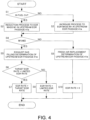
- FIG. 4 is a flowchart showing the EGR rate estimation process performed by the controller 50.
- the controller 50 includes a determination control unit and an estimation control unit by being programmed to execute the process shown in this flowchart.
- step S1 the controller 50 determines whether the fuel is being cut. Whether the fuel is being cut can be determined by whether a predetermined fuel cut execution condition is satisfied. If an affirmative determination is made in step S1, the process proceeds to step S2.
- step S2 the controller 50 performs a reduction process to the EGR mass M1 in the upstream EGR passage 41a.
- the reduction process to the EGR mass M1 is a process for reducing the EGR mass M1 by the above fresh air replacement mass, and since the exhaust gas is replaced with the fresh air in the upstream EGR passage 41a during the fuel cut, the EGR mass M1 is reduced.
- step S2 the process proceeds to step S4.
- step S4 the controller 50 determines whether the EGR mass M1 is equal to or greater than the EGR mass M2. If an affirmative determination is made in step S4, it is determined that the upstream EGR passage 41a is filled with the exhaust gas. When the process proceeds from step S2 to step S4, since the upstream EGR passage 41a is not filled with the exhaust gas, a negative determination is made, and the process proceeds to step S9.
- step S9 the controller 50 makes a fresh air replacement determination.
- the fresh air replacement determination is a determination that the upstream EGR passage 41a is being replaced with the fresh air, in other words, a determination that the upstream EGR passage 41a is not filled with the exhaust gas.
- step S10 the controller 50 determines the EGR rate in the EGR valve 43 to zero. As a result, when the upstream EGR passage 41a is not filled with the exhaust gas, the EGR rate in the EGR valve 43 is estimated to be zero. After step S10, the process ends temporarily.
- step S2 the EGR mass M1 is reduced in step S2 according to an execution time of the fuel cut. Then, when the fuel injection is restarted and the fuel is not being cut, a negative determination is made in step S1, and the process proceeds to step S3.
- step S3 the controller 50 performs an increase process to the EGR mass M1 in the upstream EGR passage 41a.
- the increase process to the EGR mass M1 is a process for increasing the EGR mass M1 by the above EGR filling mass. After step S3, the process proceeds to step S4.
- step S4 when the EGR mass M1 is smaller than the EGR mass M2, a negative determination is made, and the process proceeds to step S9 and further to step S10. That is, even when the fuel injection is restarted, as long as the upstream EGR passage 41a is not filled with the exhaust gas, the fresh air remaining in the upstream EGR passage 41a passes through the EGR valve 43, so that the EGR rate is estimated to be zero.
- step S10 the process ends temporarily.
- step S4 the same process is repeated until the upstream EGR passage 41a is not filled with the exhaust gas.
- step S4 an affirmative determination is made in step S4, and the process proceeds to step S5.
- step S5 the controller 50 makes an exhaust gas filling determination.
- the exhaust gas filling determination is a determination that the upstream EGR passage 41a is filled with the exhaust gas, and the EGR rate in the EGR valve 43 increases after the upstream EGR passage 41a is filled with the exhaust gas after the EGR is restarted.
- step S6 the process proceeds to step S6.
- step S6 the controller 50 determines whether the limited EGR rate is higher than the target EGR rate.
- the limited EGR rate is obtained by adding the change limited amount to the EGR rate, and is smaller than the target EGR rate immediately after the negative determination is switched to an affirmative determination in step S4. Therefore, in this case, a negative determination is made in step S6, and the process proceeds to step S8.
- step S8 the controller 50 determines the EGR rate as the limited EGR rate. As a result, when the limited EGR rate is equal to or less than the target EGR rate, the EGR rate in the EGR valve 43 is estimated to be the limited EGR rate. After step S8, the process ends temporarily.
- step S6 the same process is repeated when the limited EGR rate is equal to or less than the target EGR rate. Then, when the limited EGR rate becomes higher than the target EGR rate, an affirmative determination is made in step S6, and the process proceeds to step S7.
- step S7 the controller 50 determines the EGR rate as the target EGR rate. As a result, when the limited EGR rate becomes higher than the target EGR rate, the EGR rate in the EGR valve 43 is estimated to be the target EGR rate. After step S7, the process ends temporarily.
- step S4 step S5, and step S8, a gas replacement state by the exhaust gas and the fresh air in the upstream EGR passage 41a is determined. Further, in step S7, step S8 and step S10, the EGR rate is estimated based on a result of the determination. Further, by repeatedly executing the processes of step S1, step S2, step S4, and step S9, it is determined whether fresh air replacement is being executed according to the execution time of the fuel cut. When a negative determination in made in step S1 and then the process proceeds to step S10, the EGR rate after the EGR is restarted is estimated to be zero.
- FIG. 5 is a diagram showing an example of a timing chart corresponding to the flowchart shown in FIG. 4 .
- An EGR rate shown by a broken line indicates the target EGR rate.
- the EGR is stopped at a timing T1.
- the EGR valve 43 is fully closed from the timing T 1.
- the fuel cut is started.
- the inside of the upstream EGR passage 41a begins to be replaced with the fresh air due to the leakage of the exhaust gas from the gap of the EGR valve 43.
- the upstream EGR passage 41a is being replaced with the fresh air.
- the EGR mass M1 begins to decrease and becomes smaller than the EGR mass M2. That is, the inside of the upstream EGR passage 41a is not filled with the exhaust gas due to inflow of the fresh air.
- the EGR mass M 1 that starts to decrease from the timing T2 decreases with the same inclination until a timing T3 when the fuel injection is restarted.
- the fresh air replacement mass is set in advance based on the gap of the EGR valve 43 as described above. Therefore, a magnitude of the inclination of the change in the EGR mass M 1 between the timing T2 and the timing T3 indicates the fresh air replacement mass.
- the fuel cut is stopped and the fuel injection is restarted. Therefore, from the timing T3, the exhaust gas starts to be filled in the upstream EGR passage 41a due to the leakage of the fresh air from the gap of the EGR valve 43. As a result, the EGR mass M 1 begins to increase from the timing T3.
- the EGR mass M1 that starts to increase from the timing T3 increases with the same inclination until a timing T4 when the EGR is restarted.
- the EGR filling mass before the EGR is restarted is set in advance based on the gap of the EGR valve 43 as described above. Therefore, a magnitude of the inclination of the change in the EGR mass M 1 between the timing T3 and the timing T4 indicates such an EGR filling mass.
- the EGR is restarted at the timing T4.
- the EGR valve 43 is opened, and the EGR mass M1 begins to increase in a larger degree than that before the EGR valve 43 is opened.
- the EGR mass M1 that starts to increase from the timing T4 increases with the same inclination until a timing T5 where the exhaust gas filling determination is made.
- the EGR filling mass after the EGR is restarted is set based on the above target EGR mass flow rate, which therefore is a flow rate of the EGR gas flowing through the upstream EGR passage 41a.
- a magnitude of the inclination of the change in the EGR mass M1 between the timing T4 and the timing T5 indicates such an EGR filling mass.
- a period between the timing T4 and the timing T5 indicates a period until the EGR rate starts to increase after the EGR is restarted.
- the period is set to be shorter when the flow rate of the EGR gas flowing through the upstream EGR passage 41a is large than when the flow rate is small. This is because the larger the flow rate of the EGR gas after the EGR is restarted, the faster the upstream EGR passage 41a is filled with the exhaust gas.
- Such a period can be set by setting the EGR filling mass after the EGR is restarted based on the target EGR mass flow rate, which therefore is the flow rate of the EGR gas flowing through the upstream EGR passage 41a.
- the EGR filling mass after the EGR is restarted can be set in advance using map data according to the flow rate of the EGR gas flowing through the upstream EGR passage 41a. In the flowchart shown in FIG. 4 described above, the process of step S3 corresponds to the setting of such a period.
- the EGR rate is set to zero, and the EGR mass M1 becomes the EGR mass M2 at the timing T5. As a result, the exhaust gas filling determination of the upstream EGR passage 41a is made.
- the EGR mass M1 is set based on the target EGR mass flow rate. Therefore, the above exhaust gas filling determination is made based on the flow rate of the EGR gas flowing through the upstream EGR passage 41a.
- the process of step S4 following step S3 and the process of step S5 correspond to making such an exhaust gas filling determination.
- the EGR rate is set as the limited EGR rate according to the exhaust gas filling determination, and the EGR rate starts to increase.
- the EGR rate gradually increases from the timing T5 by the limited change amount. Further, the EGR rate increases with the same inclination until a timing T6 when the target EGR rate is reached. Therefore, a magnitude of the inclination of the change in the EGR rate between the timing T5 and the timing T6 indicates the limited change amount.
- a degree of increase in the EGR rate from the timing T5 after the EGR is restarted is set to be larger when the flow rate of the EGR gas is large than that when the flow rate is small. This is because the exhaust gas is actually diluted with the fresh air in the process of filling the upstream EGR passage 41a with the exhaust gas from the timing T4 when the EGR is restarted, and because the larger the flow rate of the EGR gas, the shorter a dilution time, and the more difficult it is for the exhaust gas to be diluted.
- Such a degree of increase can be set by setting the limited change amount based on the target EGR mass flow rate, which therefore is the flow rate of the EGR gas flowing through the upstream EGR passage 41a.
- the limited change amount can be set in advance using map data according to the flow rate of the EGR gas flowing through the upstream EGR passage 41a.
- the EGR rate is estimated to be the target EGR rate from the timing T6.
- the EGR rate in the intake and exhaust system 10, 20 of the internal combustion engine 1 is estimated.
- the intake and exhaust system 10, 20 of the internal combustion engine 1 includes the intake system 10, the exhaust system 20, and the EGR device 40 including the EGR passage 41 and the EGR valve 43.
- the EGR estimation method for the internal combustion engine 1 includes determining the gas replacement state by the exhaust gas and the fresh air in the upstream EGR passage 41a when the fuel cut of the internal combustion engine 1 is started and the EGR valve 43 is fully closed, and estimating the EGR rate based on a result of the determination.
- the gas replacement state in the upstream EGR passage 41a can be reflected in estimating the EGR rate. Therefore, when the fuel cut is started and the EGR valve 43 is fully closed, even when the exhaust gas inside of the upstream EGR passage 41a is replaced with the fresh air, a more accurate EGR rate can be estimated.
- whether the fresh air replacement is being executed is determined according to the execution time of the fuel cut, that is, whether the upstream EGR passage 41a is not filled with the exhaust gas due to the inflow of the fresh air is determined.
- the gas replacement state in the upstream EGR passage 41a where the exhaust gas is replaced with the fresh air by leaking the exhaust gas through the gap of the EGR valve 43 during the fuel cut can be appropriately determined. Therefore, it is possible to estimate the EGR rate more accurately.
- the EGR rate after the EGR is restarted is estimated to be zero.
- the EGR rate is estimated to be zero in light of that the fresh air remaining in the upstream EGR passage 41a first flows into the EGR valve 43 after the EGR is restarted, so that the EGR rate can be estimated more accurately.
- the period until the start of increase in the EGR rate after the EGR is restarted is shorter when the flow rate of the EGR gas flowing through the upstream EGR passage 41a is large than that when the flow rate is small.
- the EGR rate can start to increase at an appropriate timing after the EGR is restarted in light of that the larger the flow rate of the EGR gas after the EGR is restarted, the earlier the upstream EGR passage 41a is filled with the exhaust gas.
- the degree of increase in the EGR rate after the EGR is restarted is larger when the flow rate of the EGR gas flowing through the upstream EGR passage 41a is large than that when the flow rate is small.
- the EGR rate can be increased in an appropriate degree after the EGR is restarted in light of that the larger the flow rate of the EGR gas after the EGR is restarted, the more difficult it is for the exhaust gas to be diluted.
- the estimated EGR rate may be an EGR rate at a predetermined position from the downstream EGR passage 41b to the internal combustion engine 1, such as the EGR rate of the gas flowing into the cylinder of the internal combustion engine 1.
- Such an EGR rate can be estimated, for example, by correcting the timing at which the EGR gas arrives and the EGR rate according to the distance from the EGR valve 43, the inflow, and the like.
- the EGR estimation method for the internal combustion engine 1 and the case where the EGR estimation device for the internal combustion engine 1 is implemented by the controller 50 is described.
- the EGR estimation method for the internal combustion engine 1 and the EGR estimation device for the internal combustion engine 1 may be implemented by a plurality of controllers instead of a single controller 50.
Landscapes
- Engineering & Computer Science (AREA)
- Chemical & Material Sciences (AREA)
- Combustion & Propulsion (AREA)
- Mechanical Engineering (AREA)
- General Engineering & Computer Science (AREA)
- Exhaust-Gas Circulating Devices (AREA)
- Output Control And Ontrol Of Special Type Engine (AREA)
- Combined Controls Of Internal Combustion Engines (AREA)
Abstract
Description
- The present invention relates to EGR estimation of an internal combustion engine.
-
JP2016-211456A - Even if the EGR valve is fully closed, a gap may occur due to a structure thereof. In this case, even if fuel cut of an internal combustion engine is started when the EGR valve is fully closed, the exhaust gas may leak from the EGR valve to an intake passage side through the gap. As a result, an inside of an upstream EGR passage, that is, a portion between the EGR valve and an exhaust passage, is replaced with fresh air from an upstream side according to the leakage of the exhaust gas during the fuel cut.
- In this case, even if the EGR valve is opened by restarting EGR after fuel injection of the internal combustion engine is restarted, the fresh air remaining in the upstream EGR passage first flows into the EGR valve. As a result, the EGR gas, which is the exhaust gas recirculated, may not reach the EGR valve immediately. Therefore, in light of such a flow mode of the gas, it is desired to estimate a more accurate EGR rate when the fuel cut is started when the EGR valve is fully closed.
- The present invention is made in view of such a problem, and an object of the present invention is to estimate a more accurate EGR rate when the fuel cut is started when the EGR valve is fully closed.
- An EGR estimation method for internal combustion engines according to one embodiment of this invention is an EGR estimation method for an internal combustion engine that estimates an EGR rate in an intake and exhaust system of an internal combustion engine, the intake and exhaust system of an internal combustion engine including: an intake system including an intake passage that is connected to an internal combustion engine, an exhaust system including an exhaust passage that is connected to the internal combustion engine, and the intake and exhaust system being provided with an EGR device including an EGR passage that connects the intake passage and the exhaust passage and an EGR valve that is provided in the EGR passage, the EGR estimation method comprising: determining a gas replacement state by exhaust gas and fresh air in an upstream EGR passage, which is a portion of the EGR passage between the EGR valve and the exhaust passage, when fuel cut of the internal combustion engine is started and the EGR valve is fully closed; and estimating the EGR rate based on a result of the determination.
- According to another embodiment of the invention, there is provided an EGR estimation device for internal combustion engines corresponding to the above EGR estimation method for an internal combustion engine.
-
- [
FIG. 1] FIG. 1 is a schematic configuration diagram showing a main part of a vehicle. - [
FIG. 2A] FIG. 2A is a first diagram for explaining a flow mode of gas. - [
FIG. 2B] FIG. 2B is a second diagram for explaining the flow mode of the gas. - [
FIG. 2C] FIG. 2C is a third diagram for explaining the flow mode of the gas. - [
FIG. 2D] FIG. 2D is a fourth diagram for explaining the flow mode of the gas. - [
FIG. 2E] FIG. 2E is a fifth diagram for explaining the flow mode of the gas. - [
FIG. 3] FIG. 3 is a control block diagram showing an EGR rate estimation process. - [
FIG. 4] FIG. 4 is a flowchart showing the EGR rate estimation process. - [
FIG. 5] FIG. 5 is a diagram showing an example of a timing chart. - Hereinafter, an embodiment of the present invention will be described with reference to the accompanying drawings.
-
FIG. 1 is a diagram showing a main part of a vehicle. The vehicle includes aninternal combustion engine 1, anintake system 10, anexhaust system 20, asupercharger 30, anEGR device 40, and acontroller 50. - The
intake system 10 includes anintake passage 11, anair cleaner 12, anair flow meter 13, anintake throttle valve 14, anintercooler 15, athrottle valve 16, acollector 17, acompressor 31, anintake bypass passage 18, and arecirculation valve 19. Theintake passage 11 connects theair cleaner 12 and theinternal combustion engine 1 and circulates intake air introduced into theinternal combustion engine 1. Theintake passage 11 is provided with theair cleaner 12, theair flow meter 13, theintake throttle valve 14, thecompressor 31, theintercooler 15, thethrottle valve 16, and thecollector 17 in this order from an upstream side. - The
air cleaner 12 removes foreign matters contained in the intake air. Theair flow meter 13 measures a flow rate of the intake air. Theintake throttle valve 14 is provided in a portion of theintake passage 11, which is on an upstream side of anEGR convergence portion 11a to which an EGRpassage 41 is connected, which will be described later. Theintake throttle valve 14 increases a recirculation amount of exhaust gas through theEGR passage 41 by reducing an opening degree. - The
intercooler 15 cools the supercharged intake air. Thethrottle valve 16 adjusts an amount of the intake air introduced into theinternal combustion engine 1. Thecollector 17 temporarily stores the intake air. Thecompressor 31 is a compressor of thesupercharger 30 and compresses the intake air. - The
exhaust system 20 includes anexhaust passage 21, anupstream catalyst 22, adownstream catalyst 23, and aturbine 32. Theexhaust passage 21 is connected to theinternal combustion engine 1 and circulates exhaust gas discharged from theinternal combustion engine 1. Theexhaust passage 21 is provided with theturbine 32, theupstream catalyst 22, and thedownstream catalyst 23 in this order from an upstream side. Theupstream catalyst 22 and thedownstream catalyst 23 purify the exhaust gas. Theturbine 32 is the turbine of thesupercharger 30 and recovers energy from the exhaust gas. - The
supercharger 30 compresses the intake air and then supplies to theinternal combustion engine 1. Thesupercharger 30 is a turbocharger and includes thecompressor 31, theturbine 32, and ashaft 33. Thesupercharger 30 is provided in theintake passage 11 and theexhaust passage 21 by providing thecompressor 31 in theintake passage 11 and theturbine 32 in theexhaust passage 21. In thesupercharger 30, when theturbine 32 is rotated by the exhaust gas, thecompressor 31 is rotated via theshaft 33 to compress the intake air. In thecompressor 31, a pair of compressor wheels arranged in a back-to-back direction are provided on theshaft 33, and the intake air is compressed by the pair of compressor wheels. Theturbine 32 is provided with an exhaust bypass passage, and the exhaust bypass passage is provided with a waste gate valve (not shown) that adjusts a flow rate of the flowing exhaust gas. - The EGR
device 40 includes the EGRpassage 41, anEGR cooler 42, and anEGR valve 43. TheEGR device 40 recirculates the exhaust gas from theexhaust passage 21 to theintake passage 11. - The
EGR passage 41 connects theexhaust passage 21 and theintake passage 11. TheEGR passage 41 recirculates a part of the exhaust gas flowing through theexhaust passage 21 to theintake passage 11 as EGR gas. TheEGR passage 41 is provided with theEGR cooler 42 and theEGR valve 43. TheEGR cooler 42 cools the EGR gas flowing through theEGR passage 41. TheEGR valve 43 adjusts a flow rate of the EGR gas flowing through theEGR passage 41. TheEGR valve 43 includes, for example, a butterfly valve. - The
EGR passage 41 includes anupstream EGR passage 41a, which is a portion between theEGR valve 43 and theexhaust passage 21, and adownstream EGR passage 41b, which is a portion between theEGR valve 43 and theintake passage 11. It can be understood that theupstream EGR passage 41a includes theEGR cooler 42. - The
EGR device 40, specifically, theEGR passage 41 connects a portion downstream of thesupercharger 30, that is, theturbine 32 in theexhaust passage 21, and a portion upstream of thesupercharger 30, that is, thecompressor 31 in theintake passage 11. In this way, theEGR passage 41 connecting theintake passage 11 and theexhaust passage 21 forms an EGR path of a low pressure loop, that is, an LPL. More specifically, theEGR passage 41 connects a portion of theexhaust passage 21 between theupstream catalyst 22 and thedownstream catalyst 23 and a portion of theintake passage 11 between theintake throttle valve 14 and thecompressor 31. - The
intake bypass passage 18 connects an upstream pressure portion and a downstream pressure portion of thesupercharger 30 in theintake system 10. The upstream pressure portion is a portion of theintake passage 11 on an upstream side of thesupercharger 30 and on a downstream side of theEGR convergence portion 11a. The downstream pressure portion is a portion of theintake passage 11 on a downstream side of thesupercharger 30 and on an upstream side of theintercooler 15. Connecting to the downstream pressure portion of thesupercharger 30 in theintake system 10 includes connecting to thecompressor 31 so that the compressed intake air can flow into theintake bypass passage 18. - The
recirculation valve 19 is provided in theintake bypass passage 18. Therecirculation valve 19 includes an on-off valve. During supercharging, a downstream pressure of thesupercharger 30 is higher than an upstream pressure thereof. Therefore, when therecirculation valve 19 is opened during the supercharging, the intake air compressed by thecompressor 31 is returned to theintake passage 11 on the portion upstream of thesupercharger 30 via theintake bypass passage 18. - The
controller 50 is an electronic control device, and in addition to theair flow meter 13, signals from various sensors and switches such as acrank angle sensor 71 and anaccelerator position sensor 72 are input to thecontroller 50. Thecrank angle sensor 71 generates a crank angle signal for each predetermined crank angle. The crank angle signal is used as a signal representing a rotation speed NE of theinternal combustion engine 1. Theaccelerator position sensor 72 detects an amount of depression of an accelerator pedal of the vehicle. The amount of depression of the accelerator pedal is used as a signal representing a load of theinternal combustion engine 1. - The
controller 50 controls theintake throttle valve 14, thethrottle valve 16, therecirculation valve 19, and theEGR valve 43 in addition to theinternal combustion engine 1 based on the above input signals from the various sensors and switches. Thecontroller 50 controls theinternal combustion engine 1 by controlling an ignition timing and a fuel injection amount according to an engine operating state. The engine operating state is, for example, the rotation speed NE or the load. - Even if the
EGR valve 43 is fully closed, a gap may occur due to a structure thereof. In this case, even if fuel cut of theinternal combustion engine 1 is started when theEGR valve 43 is fully closed, the exhaust gas may leak from theEGR valve 43 to theintake passage 11 side through the gap. As a result, an inside of theupstream EGR passage 41a is replaced with fresh air from an upstream side according to the leakage of the exhaust gas during the fuel cut. - In this case, even if the
EGR valve 43 is opened by restarting EGR after fuel injection of theinternal combustion engine 1 is restarted, the fresh air remaining in theupstream EGR passage 41a first flows into theEGR valve 43. As a result, the EGR gas may not reach theEGR valve 43 immediately. Such a flow mode of the gas is described in detail as follows. -
FIGS. 2A to 2E are diagrams for explaining the flow mode of the gas.FIG. 2A shows a state during EGR operation. At this time, the exhaust gas is recirculated from theexhaust passage 21 to theintake passage 11. Therefore, as shown by hatching, the exhaust gas or the mixed gas of the exhaust gas and the intake gas flows through theexhaust passage 21, theEGR passage 41, and a portion of theintake passage 11 downstream of theEGR convergence portion 11a. -
FIG. 2B shows a state at a start of the fuel cut. The fuel cut is started when theEGR valve 43 is fully closed. As a result, the fresh air flows through theintake passage 11 and theexhaust passage 21. In this case, the exhaust gas is left in theEGR passage 41. -
FIG. 2C shows a state during the fuel cut. During the fuel cut, the exhaust gas leaks from theEGR valve 43 to theintake passage 11 side through the gap. As a result, the exhaust gas is replaced with the fresh air in theupstream EGR passage 41a, and in this case, finally, theentire EGR passage 41 is filled with the fresh air. -
FIG. 2D shows a state after the fuel injection is restarted and before theEGR valve 43 is opened. After the fuel injection is restarted, the fresh air flows through theintake passage 11 and the exhaust gas flows through theexhaust passage 21. After the fuel injection is restarted and before theEGR valve 43 is opened, the fresh air leaks through the gap of theEGR valve 43. Therefore, the exhaust gas is filled in theupstream EGR passage 41a by an amount of the fresh air leaking. The exhaust gas is gradually filled from an upstream portion of theupstream EGR passage 41a. -
FIG. 2E shows a state in which theupstream EGR passage 41a is filled with the exhaust gas after theEGR valve 43 is opened. When theEGR valve 43 is opened, the fresh air remaining in theupstream EGR passage 41a first flows into theEGR valve 43, and then the exhaust gas flows into theEGR valve 43. - Therefore, immediately after the
EGR valve 43 is opened, the EGR rate in theEGR valve 43 remains zero. The EGR rate then begins to rise after theupstream EGR passage 41a is filled with the exhaust gas as shown in FIG. 4E. - In light of such a flow mode of the gas, in the present embodiment, the EGR rate (actual EGR rate) in the
EGR valve 43 is estimated as described below. -
FIG. 3 is a control block diagram showing an EGR rate estimation process performed by thecontroller 50. A target EGR mass flowrate calculation unit 51 calculates a target EGR mass flow rate. The target EGR mass flow rate is a mass flow rate of the EGR gas according to a target EGR rate in theupstream EGR passage 41a, and is set in advance according to an engine operating state. The target EGR mass flow rate indicates a flow rate of the EGR gas flowing through theupstream EGR passage 41a according to a valve opening state of theEGR valve 43. - An EGR
mass calculation unit 52 calculates an EGR mass M1. The EGR mass M1 is a mass of the EGR gas in theupstream EGR passage 41a, and becomes an EGR mass M2 corresponding to a volume of theupstream EGR passage 41a when theupstream EGR passage 41a is filled with the exhaust gas. The EGR mass M1 is calculated as follows. - During the fuel cut, the exhaust gas is replaced with the fresh air in the
upstream EGR passage 41a as described above with reference toFIG. 2C . In this case, the EGRmass calculation unit 52 subtracts a fresh air replacement mass (an EGR mass corresponding to the fresh air replacement) from the EGR mass M1 for each JOB period of the EGR rate estimation process, thereby calculating the EGR mass M1. That is, a new EGR mass M1 is calculated by subtracting the fresh air replacement mass from the latest value of the EGR mass M1. - The fresh air replacement mass is a mass of the exhaust gas newly replaced by the fresh air in the
upstream EGR passage 41a, and is set based on the target EGR mass flow rate and the gap of theEGR valve 43. However, the EGR is stopped during the fuel cut, and the target EGR mass flow rate becomes zero. Therefore, the fresh air replacement mass can be set in advance based on the gap of theEGR valve 43 on the premise that the engine operating state is in the fuel cut. In this case, it can be understood that it is premised that the fuel is being cut based on the target EGR mass flow rate. - When the fuel cut is stopped and the fuel injection is restarted, the EGR
mass calculation unit 52 adds an EGR filling mass to the EGR mass M1 for each JOB period of the EGR rate estimation process, thereby calculating the EGR mass M1. That is, a new EGR mass M1 is calculated by adding the EGR filling mass to the latest value of the EGR mass M1. - The EGR filling mass is a mass of the exhaust gas newly filled in the
upstream EGR passage 41a, and is set based on at least the target EGR mass flow rate between the target EGR mass flow rate and the gap of theEGR valve 43. The EGR filling mass is set to different values after the fuel injection is restarted when the target EGR mass flow rate is zero and when it is not zero, that is, before and after the EGR is restarted. - After the fuel injection is restarted and before the EGR is restarted, the EGR filling mass is a value set in advance based on the gap of the
EGR valve 43, similarly to the fresh air replacement mass. When the EGR is restarted, the EGR filling mass is set based on the target EGR mass flow rate. The EGR filling mass will be further described later. The EGR mass M1 calculated by the EGRmass calculation unit 52 is input to adetermination unit 53. - The
determination unit 53 determines whether the EGR mass M2 corresponding to the volume of theupstream EGR passage 41a is equal to or less than the EGR mass M1 (whether the EGR mass M1 is equal to or more than the EGR mass M2). The EGR mass M2 is a determination value for determining whether theupstream EGR passage 41a is filled with the exhaust gas, and if an affirmative determination is made, it is determined that theupstream EGR passage 41a is filled with the exhaust gas. In this case, a signal is input from thedetermination unit 53 to aselection unit 54. - The
selection unit 54 selects an estimated EGR rate as the EGR rate in theEGR valve 43. As described above with reference toFIG. 2E , immediately after theEGR valve 43 is opened after the fuel injection is restarted, fresh air is introduced into theEGR valve 43 from theupstream EGR passage 41a, so that the EGR rate remains zero. - Therefore, the
selection unit 54 selects zero when no signal is input from thedetermination unit 53, that is, when theupstream EGR passage 41a is not filled with the exhaust gas. The selected EGR rate is input to an EGRrate determination unit 55. - The EGR
rate determination unit 55 determines the EGR rate input from theselection unit 54 as the EGR rate in theEGR valve 43. In this way, the estimated EGR rate is determined. The determined EGR rate is input to a changeamount limiting unit 56. - The change
amount limiting unit 56 limits a change amount of the EGR rate. The changeamount limiting unit 56 calculates a limited change amount of the EGR rate based on the target EGR mass flow rate, and the calculated limited change amount is added to the EGR rate input from the EGRrate determination unit 55. In this way, a limited EGR rate is calculated in which a change amount from the latest estimated EGR rate is the limited change amount. The limited change amount will be further described later. - The change
amount limiting unit 56 further selects the smaller EGR rate from the calculated limited EGR rate and the target EGR rate. As a result, the limited EGR rate is selected when the limited EGR rate is smaller than the target EGR rate, and the target EGR rate is not used. When the limited EGR rate and the target EGR rate are the same, either one may be selected. The selected EGR rate is input to theselection unit 54. - As described above with reference to
FIG. 2E , the EGR rate in theEGR valve 43 begins to rise after theupstream EGR passage 41a is filled with the exhaust gas. Therefore, when the signal from thedetermination unit 53 is input, that is, when theupstream EGR passage 41a is filled with the exhaust gas, theselection unit 54 does not select zero and selects the EGR rate input from the changeamount limiting unit 56. - As a result, when the
upstream EGR passage 41a is filled with the exhaust gas and the limited EGR rate is lower than the target EGR rate, theselection unit 54 selects the limited EGR rate that gradually increases from zero by an amount of the limited change amount. When the limited EGR rate exceeds the target EGR rate, the target EGR rate input from the changeamount limiting unit 56 is selected. -
FIG. 4 is a flowchart showing the EGR rate estimation process performed by thecontroller 50. Thecontroller 50 includes a determination control unit and an estimation control unit by being programmed to execute the process shown in this flowchart. - In step S1, the
controller 50 determines whether the fuel is being cut. Whether the fuel is being cut can be determined by whether a predetermined fuel cut execution condition is satisfied. If an affirmative determination is made in step S1, the process proceeds to step S2. - In step S2, the
controller 50 performs a reduction process to the EGR mass M1 in theupstream EGR passage 41a. The reduction process to the EGR mass M1 is a process for reducing the EGR mass M1 by the above fresh air replacement mass, and since the exhaust gas is replaced with the fresh air in theupstream EGR passage 41a during the fuel cut, the EGR mass M1 is reduced. After step S2, the process proceeds to step S4. - In step S4, the
controller 50 determines whether the EGR mass M1 is equal to or greater than the EGR mass M2. If an affirmative determination is made in step S4, it is determined that theupstream EGR passage 41a is filled with the exhaust gas. When the process proceeds from step S2 to step S4, since theupstream EGR passage 41a is not filled with the exhaust gas, a negative determination is made, and the process proceeds to step S9. - In step S9, the
controller 50 makes a fresh air replacement determination. The fresh air replacement determination is a determination that theupstream EGR passage 41a is being replaced with the fresh air, in other words, a determination that theupstream EGR passage 41a is not filled with the exhaust gas. After step S9, the process proceeds to step S10. - In step S10, the
controller 50 determines the EGR rate in theEGR valve 43 to zero. As a result, when theupstream EGR passage 41a is not filled with the exhaust gas, the EGR rate in theEGR valve 43 is estimated to be zero. After step S10, the process ends temporarily. - In a subsequent routine, the same process is repeated during the fuel cut, and the EGR rate is estimated to be zero. In this case, the EGR mass M1 is reduced in step S2 according to an execution time of the fuel cut. Then, when the fuel injection is restarted and the fuel is not being cut, a negative determination is made in step S1, and the process proceeds to step S3.
- In step S3, the
controller 50 performs an increase process to the EGR mass M1 in theupstream EGR passage 41a. The increase process to the EGR mass M1 is a process for increasing the EGR mass M1 by the above EGR filling mass. After step S3, the process proceeds to step S4. - In step S4, when the EGR mass M1 is smaller than the EGR mass M2, a negative determination is made, and the process proceeds to step S9 and further to step S10. That is, even when the fuel injection is restarted, as long as the
upstream EGR passage 41a is not filled with the exhaust gas, the fresh air remaining in theupstream EGR passage 41a passes through theEGR valve 43, so that the EGR rate is estimated to be zero. After step S10, the process ends temporarily. - In the subsequent routine, the same process is repeated until the
upstream EGR passage 41a is not filled with the exhaust gas. When theupstream EGR passage 41a is filled with the exhaust gas, an affirmative determination is made in step S4, and the process proceeds to step S5. - In step S5, the
controller 50 makes an exhaust gas filling determination. The exhaust gas filling determination is a determination that theupstream EGR passage 41a is filled with the exhaust gas, and the EGR rate in theEGR valve 43 increases after theupstream EGR passage 41a is filled with the exhaust gas after the EGR is restarted. After step S5, the process proceeds to step S6. - In step S6, the
controller 50 determines whether the limited EGR rate is higher than the target EGR rate. As described above, the limited EGR rate is obtained by adding the change limited amount to the EGR rate, and is smaller than the target EGR rate immediately after the negative determination is switched to an affirmative determination in step S4. Therefore, in this case, a negative determination is made in step S6, and the process proceeds to step S8. - In step S8, the
controller 50 determines the EGR rate as the limited EGR rate. As a result, when the limited EGR rate is equal to or less than the target EGR rate, the EGR rate in theEGR valve 43 is estimated to be the limited EGR rate. After step S8, the process ends temporarily. - In the subsequent routine, the same process is repeated when the limited EGR rate is equal to or less than the target EGR rate. Then, when the limited EGR rate becomes higher than the target EGR rate, an affirmative determination is made in step S6, and the process proceeds to step S7.
- In step S7, the
controller 50 determines the EGR rate as the target EGR rate. As a result, when the limited EGR rate becomes higher than the target EGR rate, the EGR rate in theEGR valve 43 is estimated to be the target EGR rate. After step S7, the process ends temporarily. - In this flowchart, in step S4, step S5, and step S8, a gas replacement state by the exhaust gas and the fresh air in the
upstream EGR passage 41a is determined. Further, in step S7, step S8 and step S10, the EGR rate is estimated based on a result of the determination. Further, by repeatedly executing the processes of step S1, step S2, step S4, and step S9, it is determined whether fresh air replacement is being executed according to the execution time of the fuel cut. When a negative determination in made in step S1 and then the process proceeds to step S10, the EGR rate after the EGR is restarted is estimated to be zero. -
FIG. 5 is a diagram showing an example of a timing chart corresponding to the flowchart shown inFIG. 4 . An EGR rate shown by a broken line indicates the target EGR rate. The EGR is stopped at a timing T1. As a result, theEGR valve 43 is fully closed from thetiming T 1. - At a timing T2, the fuel cut is started. As a result, from the timing T2, the inside of the
upstream EGR passage 41a begins to be replaced with the fresh air due to the leakage of the exhaust gas from the gap of theEGR valve 43. In other words, theupstream EGR passage 41a is being replaced with the fresh air. From the timing T2, the EGR mass M1 begins to decrease and becomes smaller than the EGR mass M2. That is, the inside of theupstream EGR passage 41a is not filled with the exhaust gas due to inflow of the fresh air. - The
EGR mass M 1 that starts to decrease from the timing T2 decreases with the same inclination until a timing T3 when the fuel injection is restarted. The fresh air replacement mass is set in advance based on the gap of theEGR valve 43 as described above. Therefore, a magnitude of the inclination of the change in theEGR mass M 1 between the timing T2 and the timing T3 indicates the fresh air replacement mass. - At the timing T3, the fuel cut is stopped and the fuel injection is restarted. Therefore, from the timing T3, the exhaust gas starts to be filled in the
upstream EGR passage 41a due to the leakage of the fresh air from the gap of theEGR valve 43. As a result, theEGR mass M 1 begins to increase from the timing T3. - The EGR mass M1 that starts to increase from the timing T3 increases with the same inclination until a timing T4 when the EGR is restarted. After the fuel injection is restarted, the EGR filling mass before the EGR is restarted is set in advance based on the gap of the
EGR valve 43 as described above. Therefore, a magnitude of the inclination of the change in theEGR mass M 1 between the timing T3 and the timing T4 indicates such an EGR filling mass. - The EGR is restarted at the timing T4. As a result, the
EGR valve 43 is opened, and the EGR mass M1 begins to increase in a larger degree than that before theEGR valve 43 is opened. The EGR mass M1 that starts to increase from the timing T4 increases with the same inclination until a timing T5 where the exhaust gas filling determination is made. - The EGR filling mass after the EGR is restarted is set based on the above target EGR mass flow rate, which therefore is a flow rate of the EGR gas flowing through the
upstream EGR passage 41a. A magnitude of the inclination of the change in the EGR mass M1 between the timing T4 and the timing T5 indicates such an EGR filling mass. - A period between the timing T4 and the timing T5 indicates a period until the EGR rate starts to increase after the EGR is restarted. The period is set to be shorter when the flow rate of the EGR gas flowing through the
upstream EGR passage 41a is large than when the flow rate is small. This is because the larger the flow rate of the EGR gas after the EGR is restarted, the faster theupstream EGR passage 41a is filled with the exhaust gas. - Such a period can be set by setting the EGR filling mass after the EGR is restarted based on the target EGR mass flow rate, which therefore is the flow rate of the EGR gas flowing through the
upstream EGR passage 41a. The EGR filling mass after the EGR is restarted can be set in advance using map data according to the flow rate of the EGR gas flowing through theupstream EGR passage 41a. In the flowchart shown inFIG. 4 described above, the process of step S3 corresponds to the setting of such a period. - Since the EGR mass M1 is smaller than the EGR mass M2 from the timing T2 to the timing T5, the EGR rate is set to zero, and the EGR mass M1 becomes the EGR mass M2 at the timing T5. As a result, the exhaust gas filling determination of the
upstream EGR passage 41a is made. - As described above, the EGR mass M1 is set based on the target EGR mass flow rate. Therefore, the above exhaust gas filling determination is made based on the flow rate of the EGR gas flowing through the
upstream EGR passage 41a. In the flowchart shown inFIG. 4 described above, the process of step S4 following step S3 and the process of step S5 correspond to making such an exhaust gas filling determination. - From the timing T5, the EGR rate is set as the limited EGR rate according to the exhaust gas filling determination, and the EGR rate starts to increase. The EGR rate gradually increases from the timing T5 by the limited change amount. Further, the EGR rate increases with the same inclination until a timing T6 when the target EGR rate is reached. Therefore, a magnitude of the inclination of the change in the EGR rate between the timing T5 and the timing T6 indicates the limited change amount.
- A degree of increase in the EGR rate from the timing T5 after the EGR is restarted is set to be larger when the flow rate of the EGR gas is large than that when the flow rate is small. This is because the exhaust gas is actually diluted with the fresh air in the process of filling the
upstream EGR passage 41a with the exhaust gas from the timing T4 when the EGR is restarted, and because the larger the flow rate of the EGR gas, the shorter a dilution time, and the more difficult it is for the exhaust gas to be diluted. - Such a degree of increase can be set by setting the limited change amount based on the target EGR mass flow rate, which therefore is the flow rate of the EGR gas flowing through the
upstream EGR passage 41a. The limited change amount can be set in advance using map data according to the flow rate of the EGR gas flowing through theupstream EGR passage 41a. - At the timing T6, the EGR rate reaches the target EGR rate. Therefore, the EGR rate is estimated to be the target EGR rate from the timing T6.
- Next, main functions and effects of the present embodiment will be described.
- In the EGR estimation method for the
internal combustion engine 1 according to the present embodiment, the EGR rate in the intake andexhaust system internal combustion engine 1 is estimated. The intake andexhaust system internal combustion engine 1 includes theintake system 10, theexhaust system 20, and theEGR device 40 including theEGR passage 41 and theEGR valve 43. The EGR estimation method for theinternal combustion engine 1 includes determining the gas replacement state by the exhaust gas and the fresh air in theupstream EGR passage 41a when the fuel cut of theinternal combustion engine 1 is started and theEGR valve 43 is fully closed, and estimating the EGR rate based on a result of the determination. - According to such a method, the gas replacement state in the
upstream EGR passage 41a can be reflected in estimating the EGR rate. Therefore, when the fuel cut is started and theEGR valve 43 is fully closed, even when the exhaust gas inside of theupstream EGR passage 41a is replaced with the fresh air, a more accurate EGR rate can be estimated. - In the present embodiment, whether the fresh air replacement is being executed is determined according to the execution time of the fuel cut, that is, whether the
upstream EGR passage 41a is not filled with the exhaust gas due to the inflow of the fresh air is determined. - According to such a method, the gas replacement state in the
upstream EGR passage 41a where the exhaust gas is replaced with the fresh air by leaking the exhaust gas through the gap of theEGR valve 43 during the fuel cut can be appropriately determined. Therefore, it is possible to estimate the EGR rate more accurately. - In the present embodiment, when it is determined that the inside of the
upstream EGR passage 41a is not filled with the exhaust gas due to the inflow of the fresh air, the EGR rate after the EGR is restarted is estimated to be zero. - According to such a method, the EGR rate is estimated to be zero in light of that the fresh air remaining in the
upstream EGR passage 41a first flows into theEGR valve 43 after the EGR is restarted, so that the EGR rate can be estimated more accurately. - In the present embodiment, after the fuel injection of the
internal combustion engine 1 is restarted, it is determined whether the inside of theupstream EGR passage 41a is replaced with the exhaust gas based on the flow rate of the EGR gas flowing through theupstream EGR passage 41a. - According to such a method, it is possible to appropriately determine whether the inside of the
upstream EGR passage 41a is replaced with the exhaust gas, so that the EGR rate after the fuel injection is restarted can be appropriately estimated. - In the present embodiment, the period until the start of increase in the EGR rate after the EGR is restarted is shorter when the flow rate of the EGR gas flowing through the
upstream EGR passage 41a is large than that when the flow rate is small. - According to such a method, the EGR rate can start to increase at an appropriate timing after the EGR is restarted in light of that the larger the flow rate of the EGR gas after the EGR is restarted, the earlier the
upstream EGR passage 41a is filled with the exhaust gas. - In the present embodiment, the degree of increase in the EGR rate after the EGR is restarted is larger when the flow rate of the EGR gas flowing through the
upstream EGR passage 41a is large than that when the flow rate is small. - According to such a method, the EGR rate can be increased in an appropriate degree after the EGR is restarted in light of that the larger the flow rate of the EGR gas after the EGR is restarted, the more difficult it is for the exhaust gas to be diluted.
- Although the embodiment of the present invention has been described above, the above-mentioned embodiment is merely a part of application examples of the present invention, and does not mean that the technical scope of the present invention is limited to the specific configurations of the above-mentioned embodiment.
- For example, in the above embodiment, the case of estimating the EGR rate in the
EGR valve 43 is described. However, the estimated EGR rate may be an EGR rate at a predetermined position from thedownstream EGR passage 41b to theinternal combustion engine 1, such as the EGR rate of the gas flowing into the cylinder of theinternal combustion engine 1. Such an EGR rate can be estimated, for example, by correcting the timing at which the EGR gas arrives and the EGR rate according to the distance from theEGR valve 43, the inflow, and the like. - For example, in the above embodiment, the EGR estimation method for the
internal combustion engine 1 and the case where the EGR estimation device for theinternal combustion engine 1 is implemented by thecontroller 50 is described. However, the EGR estimation method for theinternal combustion engine 1 and the EGR estimation device for theinternal combustion engine 1 may be implemented by a plurality of controllers instead of asingle controller 50.
Claims (7)
- An EGR estimation method for an internal combustion engine that estimates an EGR rate in an intake and exhaust system of an internal combustion engine, the intake and exhaust system of an internal combustion engine including: an intake system including an intake passage that is connected to an internal combustion engine, an exhaust system including an exhaust passage that is connected to the internal combustion engine, and the intake and exhaust system being provided with an EGR device including an EGR passage that connects the intake passage and the exhaust passage and an EGR valve that is provided in the EGR passage, the EGR estimation method comprising:determining a gas replacement state by exhaust gas and fresh air in an upstream EGR passage, which is a portion of the EGR passage between the EGR valve and the exhaust passage, when fuel cut of the internal combustion engine is started when the EGR valve is fully closed; andestimating the EGR rate based on a result of the determination.
- The EGR estimation method for an internal combustion engine according to claim 1, wherein
whether an inside of the upstream EGR passage is not filled with the exhaust gas due to inflow of the fresh air is determined according to an execution time of the fuel cut. - The EGR estimation method for an internal combustion engine according to claim 2, wherein
when it is determined that the upstream EGR passage is not filled with the exhaust gas due to the inflow of the fresh air, the EGR rate after EGR is restarted is estimated to be zero. - The EGR estimation method for an internal combustion engine according to any one of claims 1 to 3, wherein
after fuel injection of the internal combustion engine is restarted, it is determined whether the inside of the upstream EGR passage is replaced with the exhaust gas based on a flow rate of EGR gas flowing through the upstream EGR passage. - The EGR estimation method for an internal combustion engine according to claim 4, further comprising:
setting a period until the EGR rate after the EGR is restarted starts to increase to be shorter when the flow rate of the EGR gas is large than that when the flow rate is small. - The EGR estimation method for an internal combustion engine according to claim 4 or 5, further comprising:
setting a degree of increase in the EGR rate after the EGR is restarted to be larger when the flow rate of the EGR gas is large than that when the flow rate is small. - An EGR estimation device for an internal combustion engine that estimates an EGR rate in an intake and exhaust system of an internal combustion engine, the intake and exhaust system of an internal combustion engine including: an intake system including an intake passage that is connected to an internal combustion engine, an exhaust system including an exhaust passage that is connected to the internal combustion engine, and the intake and exhaust system being provided with an EGR device including an EGR passage that connects the intake passage and the exhaust passage and an EGR valve that is provided in the EGR passage, the EGR estimation device comprising:a determination control unit that determines a gas replacement state by exhaust gas and fresh air in an upstream EGR passage, which is a portion of the EGR passage between the EGR valve and the exhaust passage, when fuel cut of the internal combustion engine is started and the EGR valve is fully closed; andan estimation control unit that estimates the EGR rate based on a result of the determination.
Applications Claiming Priority (1)
| Application Number | Priority Date | Filing Date | Title |
|---|---|---|---|
| PCT/JP2020/015230 WO2021199411A1 (en) | 2020-04-02 | 2020-04-02 | Egr estimation method for internal combustion engine, and egr estimation device for internal combustion engine |
Publications (2)
| Publication Number | Publication Date |
|---|---|
| EP4130457A1 true EP4130457A1 (en) | 2023-02-08 |
| EP4130457A4 EP4130457A4 (en) | 2023-09-06 |
Family
ID=77927445
Family Applications (1)
| Application Number | Title | Priority Date | Filing Date |
|---|---|---|---|
| EP20928985.9A Withdrawn EP4130457A4 (en) | 2020-04-02 | 2020-04-02 | Egr estimation method for internal combustion engine, and egr estimation device for internal combustion engine |
Country Status (5)
| Country | Link |
|---|---|
| US (1) | US11898509B2 (en) |
| EP (1) | EP4130457A4 (en) |
| JP (1) | JP7306570B2 (en) |
| CN (1) | CN115516199B (en) |
| WO (1) | WO2021199411A1 (en) |
Family Cites Families (16)
| Publication number | Priority date | Publication date | Assignee | Title |
|---|---|---|---|---|
| JPH04284147A (en) * | 1991-03-12 | 1992-10-08 | Mazda Motor Corp | Exhaust gas recirculating device for engine |
| JP4403876B2 (en) * | 2004-05-17 | 2010-01-27 | トヨタ自動車株式会社 | Compression ignition internal combustion engine |
| JP2010096001A (en) | 2008-10-14 | 2010-04-30 | Daihatsu Motor Co Ltd | Control device |
| DE102009058130A1 (en) * | 2009-12-12 | 2011-06-16 | Mahle International Gmbh | Internal combustion engine system and associated operating method |
| JP2012087636A (en) * | 2010-10-15 | 2012-05-10 | Nissan Motor Co Ltd | Exhaust gas recirculation control device for internal combustion engine |
| JP5828806B2 (en) * | 2012-05-31 | 2015-12-09 | 愛三工業株式会社 | Engine exhaust gas recirculation system |
| US10174719B2 (en) | 2012-08-01 | 2019-01-08 | Nissan Motor Co., Ltd. | Control device for internal combustion engine |
| JP2014240631A (en) | 2013-06-12 | 2014-12-25 | 株式会社デンソー | Egr control device of internal combustion engine |
| JP6049577B2 (en) * | 2013-09-16 | 2016-12-21 | 愛三工業株式会社 | Exhaust gas recirculation system for turbocharged engines |
| JP2015218642A (en) * | 2014-05-16 | 2015-12-07 | 株式会社デンソー | Internal combustion engine exhaust system |
| JP2016211456A (en) | 2015-05-11 | 2016-12-15 | トヨタ自動車株式会社 | Internal combustion engine control device |
| JP6380446B2 (en) * | 2016-03-30 | 2018-08-29 | トヨタ自動車株式会社 | Vehicle control device |
| US10570836B2 (en) * | 2017-06-14 | 2020-02-25 | Aisan Kogyo Kabushiki Kaisha | EGR control apparatus for engine with supercharger and control method of EGR device for engine with supercharger |
| JP6569710B2 (en) * | 2017-09-22 | 2019-09-04 | マツダ株式会社 | Engine exhaust purification system |
| JP6614221B2 (en) * | 2017-10-02 | 2019-12-04 | トヨタ自動車株式会社 | Control device for internal combustion engine |
| JP6955214B2 (en) * | 2017-12-27 | 2021-10-27 | トヨタ自動車株式会社 | Internal combustion engine control device |
-
2020
- 2020-04-02 US US17/916,326 patent/US11898509B2/en active Active
- 2020-04-02 JP JP2022511471A patent/JP7306570B2/en active Active
- 2020-04-02 CN CN202080099203.4A patent/CN115516199B/en active Active
- 2020-04-02 WO PCT/JP2020/015230 patent/WO2021199411A1/en not_active Ceased
- 2020-04-02 EP EP20928985.9A patent/EP4130457A4/en not_active Withdrawn
Also Published As
| Publication number | Publication date |
|---|---|
| JP7306570B2 (en) | 2023-07-11 |
| WO2021199411A1 (en) | 2021-10-07 |
| JPWO2021199411A1 (en) | 2021-10-07 |
| CN115516199A (en) | 2022-12-23 |
| EP4130457A4 (en) | 2023-09-06 |
| US20230151775A1 (en) | 2023-05-18 |
| CN115516199B (en) | 2024-12-06 |
| US11898509B2 (en) | 2024-02-13 |
Similar Documents
| Publication | Publication Date | Title |
|---|---|---|
| US8096123B2 (en) | System and method for mode transition for a two-stage series sequential turbocharger | |
| US7047740B2 (en) | Boost pressure estimation apparatus for internal combustion engine with supercharger | |
| EP1375876A2 (en) | Apparatus and method for controlling EGR in an engine | |
| RU2563441C1 (en) | Control device for diesel engine with turbocharging | |
| KR101563831B1 (en) | Control apparatus for internal combustion engine | |
| US10753271B2 (en) | System for controling internal combustion engine | |
| US10428750B2 (en) | Turbocharged internal combustion engine system | |
| KR20180053356A (en) | Control device of internal combustion engine and control method of internal combustion engine | |
| US7219002B2 (en) | Control apparatus for internal combustion engine | |
| US10883429B2 (en) | Intake control method and intake control device for internal combustion engine | |
| US11898509B2 (en) | EGR estimation method for internal combustion engine and EGR estimation device for internal combustion engine | |
| US10738723B2 (en) | Controller of a turbocharged engine | |
| JP2018155167A (en) | Control device of internal combustion engine | |
| US11939928B2 (en) | EGR control method and EGR controller | |
| US8229654B2 (en) | Device for limiting output of internal combustion engine when the engine has abnormality | |
| EP4130456B1 (en) | Egr estimation method for an internal combustion engine and egr estimation device for an internal combustion engine | |
| JP2000205053A (en) | EGR control device | |
| US20220260043A1 (en) | Method of estimating actual egr ratio in egr system and egr system | |
| JP2022094558A (en) | Control device for internal combustion engine | |
| JP2022144631A (en) | Control device for internal combustion engine system | |
| JP2002021594A (en) | Exhaust gas recirculation system |
Legal Events
| Date | Code | Title | Description |
|---|---|---|---|
| STAA | Information on the status of an ep patent application or granted ep patent |
Free format text: STATUS: THE INTERNATIONAL PUBLICATION HAS BEEN MADE |
|
| PUAI | Public reference made under article 153(3) epc to a published international application that has entered the european phase |
Free format text: ORIGINAL CODE: 0009012 |
|
| STAA | Information on the status of an ep patent application or granted ep patent |
Free format text: STATUS: REQUEST FOR EXAMINATION WAS MADE |
|
| 17P | Request for examination filed |
Effective date: 20220923 |
|
| AK | Designated contracting states |
Kind code of ref document: A1 Designated state(s): AL AT BE BG CH CY CZ DE DK EE ES FI FR GB GR HR HU IE IS IT LI LT LU LV MC MK MT NL NO PL PT RO RS SE SI SK SM TR |
|
| DAV | Request for validation of the european patent (deleted) | ||
| DAX | Request for extension of the european patent (deleted) | ||
| REG | Reference to a national code |
Ref country code: DE Ref legal event code: R079 Free format text: PREVIOUS MAIN CLASS: F02M0026470000 Ipc: F02D0041000000 |
|
| A4 | Supplementary search report drawn up and despatched |
Effective date: 20230803 |
|
| RIC1 | Information provided on ipc code assigned before grant |
Ipc: F02D 41/12 20060101ALI20230728BHEP Ipc: F02M 26/06 20160101ALI20230728BHEP Ipc: F02D 41/00 20060101AFI20230728BHEP |
|
| STAA | Information on the status of an ep patent application or granted ep patent |
Free format text: STATUS: EXAMINATION IS IN PROGRESS |
|
| 17Q | First examination report despatched |
Effective date: 20240611 |
|
| STAA | Information on the status of an ep patent application or granted ep patent |
Free format text: STATUS: THE APPLICATION IS DEEMED TO BE WITHDRAWN |
|
| 18D | Application deemed to be withdrawn |
Effective date: 20250628 |