EP4130428A1 - Morphing structures for adjustable fan inlet guide vanes - Google Patents
Morphing structures for adjustable fan inlet guide vanes Download PDFInfo
- Publication number
- EP4130428A1 EP4130428A1 EP22185566.1A EP22185566A EP4130428A1 EP 4130428 A1 EP4130428 A1 EP 4130428A1 EP 22185566 A EP22185566 A EP 22185566A EP 4130428 A1 EP4130428 A1 EP 4130428A1
- Authority
- EP
- European Patent Office
- Prior art keywords
- airfoil
- control rod
- gas turbine
- turbine engine
- radial segments
- Prior art date
- Legal status (The legal status is an assumption and is not a legal conclusion. Google has not performed a legal analysis and makes no representation as to the accuracy of the status listed.)
- Granted
Links
Images


Classifications
-
- F—MECHANICAL ENGINEERING; LIGHTING; HEATING; WEAPONS; BLASTING
- F01—MACHINES OR ENGINES IN GENERAL; ENGINE PLANTS IN GENERAL; STEAM ENGINES
- F01D—NON-POSITIVE DISPLACEMENT MACHINES OR ENGINES, e.g. STEAM TURBINES
- F01D17/00—Regulating or controlling by varying flow
- F01D17/10—Final actuators
- F01D17/12—Final actuators arranged in stator parts
- F01D17/14—Final actuators arranged in stator parts varying effective cross-sectional area of nozzles or guide conduits
- F01D17/16—Final actuators arranged in stator parts varying effective cross-sectional area of nozzles or guide conduits by means of nozzle vanes
- F01D17/162—Final actuators arranged in stator parts varying effective cross-sectional area of nozzles or guide conduits by means of nozzle vanes for axial flow, i.e. the vanes turning around axes which are essentially perpendicular to the rotor centre line
-
- F—MECHANICAL ENGINEERING; LIGHTING; HEATING; WEAPONS; BLASTING
- F02—COMBUSTION ENGINES; HOT-GAS OR COMBUSTION-PRODUCT ENGINE PLANTS
- F02K—JET-PROPULSION PLANTS
- F02K3/00—Plants including a gas turbine driving a compressor or a ducted fan
- F02K3/02—Plants including a gas turbine driving a compressor or a ducted fan in which part of the working fluid by-passes the turbine and combustion chamber
- F02K3/04—Plants including a gas turbine driving a compressor or a ducted fan in which part of the working fluid by-passes the turbine and combustion chamber the plant including ducted fans, i.e. fans with high volume, low pressure outputs, for augmenting the jet thrust, e.g. of double-flow type
- F02K3/06—Plants including a gas turbine driving a compressor or a ducted fan in which part of the working fluid by-passes the turbine and combustion chamber the plant including ducted fans, i.e. fans with high volume, low pressure outputs, for augmenting the jet thrust, e.g. of double-flow type with front fan
-
- F—MECHANICAL ENGINEERING; LIGHTING; HEATING; WEAPONS; BLASTING
- F01—MACHINES OR ENGINES IN GENERAL; ENGINE PLANTS IN GENERAL; STEAM ENGINES
- F01D—NON-POSITIVE DISPLACEMENT MACHINES OR ENGINES, e.g. STEAM TURBINES
- F01D5/00—Blades; Blade-carrying members; Heating, heat-insulating, cooling or antivibration means on the blades or the members
- F01D5/12—Blades
- F01D5/14—Form or construction
- F01D5/148—Blades with variable camber, e.g. by ejection of fluid
-
- F—MECHANICAL ENGINEERING; LIGHTING; HEATING; WEAPONS; BLASTING
- F01—MACHINES OR ENGINES IN GENERAL; ENGINE PLANTS IN GENERAL; STEAM ENGINES
- F01D—NON-POSITIVE DISPLACEMENT MACHINES OR ENGINES, e.g. STEAM TURBINES
- F01D5/00—Blades; Blade-carrying members; Heating, heat-insulating, cooling or antivibration means on the blades or the members
- F01D5/12—Blades
- F01D5/28—Selecting particular materials; Particular measures relating thereto; Measures against erosion or corrosion
-
- F—MECHANICAL ENGINEERING; LIGHTING; HEATING; WEAPONS; BLASTING
- F02—COMBUSTION ENGINES; HOT-GAS OR COMBUSTION-PRODUCT ENGINE PLANTS
- F02C—GAS-TURBINE PLANTS; AIR INTAKES FOR JET-PROPULSION PLANTS; CONTROLLING FUEL SUPPLY IN AIR-BREATHING JET-PROPULSION PLANTS
- F02C9/00—Controlling gas-turbine plants; Controlling fuel supply in air- breathing jet-propulsion plants
- F02C9/16—Control of working fluid flow
- F02C9/20—Control of working fluid flow by throttling; by adjusting vanes
-
- F—MECHANICAL ENGINEERING; LIGHTING; HEATING; WEAPONS; BLASTING
- F02—COMBUSTION ENGINES; HOT-GAS OR COMBUSTION-PRODUCT ENGINE PLANTS
- F02C—GAS-TURBINE PLANTS; AIR INTAKES FOR JET-PROPULSION PLANTS; CONTROLLING FUEL SUPPLY IN AIR-BREATHING JET-PROPULSION PLANTS
- F02C9/00—Controlling gas-turbine plants; Controlling fuel supply in air- breathing jet-propulsion plants
- F02C9/16—Control of working fluid flow
- F02C9/20—Control of working fluid flow by throttling; by adjusting vanes
- F02C9/22—Control of working fluid flow by throttling; by adjusting vanes by adjusting turbine vanes
-
- F—MECHANICAL ENGINEERING; LIGHTING; HEATING; WEAPONS; BLASTING
- F02—COMBUSTION ENGINES; HOT-GAS OR COMBUSTION-PRODUCT ENGINE PLANTS
- F02C—GAS-TURBINE PLANTS; AIR INTAKES FOR JET-PROPULSION PLANTS; CONTROLLING FUEL SUPPLY IN AIR-BREATHING JET-PROPULSION PLANTS
- F02C9/00—Controlling gas-turbine plants; Controlling fuel supply in air- breathing jet-propulsion plants
- F02C9/48—Control of fuel supply conjointly with another control of the plant
- F02C9/50—Control of fuel supply conjointly with another control of the plant with control of working fluid flow
- F02C9/54—Control of fuel supply conjointly with another control of the plant with control of working fluid flow by throttling the working fluid, by adjusting vanes
-
- F—MECHANICAL ENGINEERING; LIGHTING; HEATING; WEAPONS; BLASTING
- F02—COMBUSTION ENGINES; HOT-GAS OR COMBUSTION-PRODUCT ENGINE PLANTS
- F02C—GAS-TURBINE PLANTS; AIR INTAKES FOR JET-PROPULSION PLANTS; CONTROLLING FUEL SUPPLY IN AIR-BREATHING JET-PROPULSION PLANTS
- F02C9/00—Controlling gas-turbine plants; Controlling fuel supply in air- breathing jet-propulsion plants
- F02C9/48—Control of fuel supply conjointly with another control of the plant
- F02C9/56—Control of fuel supply conjointly with another control of the plant with power transmission control
- F02C9/58—Control of fuel supply conjointly with another control of the plant with power transmission control with control of a variable-pitch propeller
-
- F—MECHANICAL ENGINEERING; LIGHTING; HEATING; WEAPONS; BLASTING
- F04—POSITIVE - DISPLACEMENT MACHINES FOR LIQUIDS; PUMPS FOR LIQUIDS OR ELASTIC FLUIDS
- F04D—NON-POSITIVE-DISPLACEMENT PUMPS
- F04D19/00—Axial-flow pumps
- F04D19/02—Multi-stage pumps
-
- F—MECHANICAL ENGINEERING; LIGHTING; HEATING; WEAPONS; BLASTING
- F04—POSITIVE - DISPLACEMENT MACHINES FOR LIQUIDS; PUMPS FOR LIQUIDS OR ELASTIC FLUIDS
- F04D—NON-POSITIVE-DISPLACEMENT PUMPS
- F04D29/00—Details, component parts, or accessories
- F04D29/02—Selection of particular materials
- F04D29/023—Selection of particular materials especially adapted for elastic fluid pumps
-
- F—MECHANICAL ENGINEERING; LIGHTING; HEATING; WEAPONS; BLASTING
- F04—POSITIVE - DISPLACEMENT MACHINES FOR LIQUIDS; PUMPS FOR LIQUIDS OR ELASTIC FLUIDS
- F04D—NON-POSITIVE-DISPLACEMENT PUMPS
- F04D29/00—Details, component parts, or accessories
- F04D29/40—Casings; Connections of working fluid
- F04D29/52—Casings; Connections of working fluid for axial pumps
- F04D29/54—Fluid-guiding means, e.g. diffusers
- F04D29/541—Specially adapted for elastic fluid pumps
- F04D29/542—Bladed diffusers
- F04D29/544—Blade shapes
-
- F—MECHANICAL ENGINEERING; LIGHTING; HEATING; WEAPONS; BLASTING
- F04—POSITIVE - DISPLACEMENT MACHINES FOR LIQUIDS; PUMPS FOR LIQUIDS OR ELASTIC FLUIDS
- F04D—NON-POSITIVE-DISPLACEMENT PUMPS
- F04D29/00—Details, component parts, or accessories
- F04D29/40—Casings; Connections of working fluid
- F04D29/52—Casings; Connections of working fluid for axial pumps
- F04D29/54—Fluid-guiding means, e.g. diffusers
- F04D29/56—Fluid-guiding means, e.g. diffusers adjustable
- F04D29/563—Fluid-guiding means, e.g. diffusers adjustable specially adapted for elastic fluid pumps
-
- F—MECHANICAL ENGINEERING; LIGHTING; HEATING; WEAPONS; BLASTING
- F05—INDEXING SCHEMES RELATING TO ENGINES OR PUMPS IN VARIOUS SUBCLASSES OF CLASSES F01-F04
- F05D—INDEXING SCHEME FOR ASPECTS RELATING TO NON-POSITIVE-DISPLACEMENT MACHINES OR ENGINES, GAS-TURBINES OR JET-PROPULSION PLANTS
- F05D2220/00—Application
- F05D2220/30—Application in turbines
- F05D2220/36—Application in turbines specially adapted for the fan of turbofan engines
-
- F—MECHANICAL ENGINEERING; LIGHTING; HEATING; WEAPONS; BLASTING
- F05—INDEXING SCHEMES RELATING TO ENGINES OR PUMPS IN VARIOUS SUBCLASSES OF CLASSES F01-F04
- F05D—INDEXING SCHEME FOR ASPECTS RELATING TO NON-POSITIVE-DISPLACEMENT MACHINES OR ENGINES, GAS-TURBINES OR JET-PROPULSION PLANTS
- F05D2240/00—Components
- F05D2240/10—Stators
- F05D2240/12—Fluid guiding means, e.g. vanes
- F05D2240/122—Fluid guiding means, e.g. vanes related to the trailing edge of a stator vane
-
- F—MECHANICAL ENGINEERING; LIGHTING; HEATING; WEAPONS; BLASTING
- F05—INDEXING SCHEMES RELATING TO ENGINES OR PUMPS IN VARIOUS SUBCLASSES OF CLASSES F01-F04
- F05D—INDEXING SCHEME FOR ASPECTS RELATING TO NON-POSITIVE-DISPLACEMENT MACHINES OR ENGINES, GAS-TURBINES OR JET-PROPULSION PLANTS
- F05D2240/00—Components
- F05D2240/10—Stators
- F05D2240/12—Fluid guiding means, e.g. vanes
- F05D2240/128—Nozzles
-
- F—MECHANICAL ENGINEERING; LIGHTING; HEATING; WEAPONS; BLASTING
- F05—INDEXING SCHEMES RELATING TO ENGINES OR PUMPS IN VARIOUS SUBCLASSES OF CLASSES F01-F04
- F05D—INDEXING SCHEME FOR ASPECTS RELATING TO NON-POSITIVE-DISPLACEMENT MACHINES OR ENGINES, GAS-TURBINES OR JET-PROPULSION PLANTS
- F05D2250/00—Geometry
- F05D2250/90—Variable geometry
-
- F—MECHANICAL ENGINEERING; LIGHTING; HEATING; WEAPONS; BLASTING
- F05—INDEXING SCHEMES RELATING TO ENGINES OR PUMPS IN VARIOUS SUBCLASSES OF CLASSES F01-F04
- F05D—INDEXING SCHEME FOR ASPECTS RELATING TO NON-POSITIVE-DISPLACEMENT MACHINES OR ENGINES, GAS-TURBINES OR JET-PROPULSION PLANTS
- F05D2260/00—Function
- F05D2260/50—Kinematic linkage, i.e. transmission of position
- F05D2260/56—Kinematic linkage, i.e. transmission of position using cams or eccentrics
-
- Y—GENERAL TAGGING OF NEW TECHNOLOGICAL DEVELOPMENTS; GENERAL TAGGING OF CROSS-SECTIONAL TECHNOLOGIES SPANNING OVER SEVERAL SECTIONS OF THE IPC; TECHNICAL SUBJECTS COVERED BY FORMER USPC CROSS-REFERENCE ART COLLECTIONS [XRACs] AND DIGESTS
- Y02—TECHNOLOGIES OR APPLICATIONS FOR MITIGATION OR ADAPTATION AGAINST CLIMATE CHANGE
- Y02T—CLIMATE CHANGE MITIGATION TECHNOLOGIES RELATED TO TRANSPORTATION
- Y02T50/00—Aeronautics or air transport
- Y02T50/60—Efficient propulsion technologies, e.g. for aircraft
Definitions
- This application relates to a gas turbine engine with fan inlet variable vanes that may morph in shape.
- Gas turbine engines typically include a fan section, a compressor section, a combustor section, and a turbine section. Air entering the compressor section is compressed and delivered into the combustion section where it is mixed with fuel and ignited to generate a high-pressure and temperature exhaust gas flow. The high-pressure and temperature exhaust gas flow expands through the turbine section to drive the compressor section and the fan section.
- the compressor section may include low and high pressure compressors, and the turbine section may also include low and high pressure turbines.
- Fan inlet variable vanes may be included in the fan section upstream of the fan.
- the vanes turn air in a desired direction as it approaches the fan.
- the desired direction may change depending on the operating condition of the engine.
- Variable vanes are typically provided with an actuator which deflects a flap on the trailing edge of the vanes such that the trailing edges change an incident angle relative to the angle of the fan blades depending on operating condition.
- the vanes have changed the fan blade incident angle by deflection of a monolithic flap such that the angular change of the trailing edge is uniform across the span of the vane.
- a gas turbine engine includes a fan section, a compressor section, and a turbine section.
- the fan section has a plurality of vane assemblies spaced circumferentially about an engine axis.
- the vane assemblies each include an airfoil extending between a leading edge and a trailing edge, a control rod extending through the airfoil, and a mechanism driven by the control rod to change the shape of the airfoil.
- the mechanism changes the shape of the trailing edge.
- the trailing edge includes a plurality of radial segments interspaced by deformable supports.
- the radial segments are one of metal, carbon fiber, and ceramic.
- the deformable supports are one of polyurethane, isoprene, silicone, and fluoroelastomer.
- control rod drives the plurality of radial segments to pivot from an initial position to a morphed position in which the radial segments each have a different angle relative to the leading edge.
- one of the control rod and the radial segments includes a plurality of protrusions and the other includes angled slots receiving the protrusions.
- control rod includes the plurality of protrusions and each radial segment includes an angled slot receiving a protrusion.
- control rod translates radially within the airfoil such that the protrusions slide within the angled slots driving the radial segments to pivot into the morphed position.
- the vanes further include a flexible skin.
- the flexible skin is comprised of one of ethylene propylene diene monomer, synthetic rubber, and thermoplastic polyurethane.
- the airfoil includes a pressure side and a suction side.
- the flexible skin on the pressure side slides relative to the flexible skin on the suction side when the airfoil changes shape.
- a single synchronization ring drives the control rod of each vane assembly to change the shape of each airfoil simultaneously.
- a first and second synchronization ring drives control rods of a first and second subset of the plurality of vane assemblies respectively.
- the first and second synchronization rings drive the control rods to change the shape of the airfoils in the first and second subset independently.
- control rod of each of the plurality of vane assemblies is driven to rotate by a separate actuator to change the shape of each airfoil independently.
- a controller controls actuation of the control rods.
- the controller actuates the control rods to change the shape of the airfoils in response to a change in operating conditions.
- the controller controls actuation of at least one synchronization ring.
- the at least one synchronization ring drives the control rod of each of the vane assemblies and drives a flap portion of each airfoil to pivot about an airfoil axis.
- the controller drives the plurality of vanes into a non-axisymmetric configuration in response to non-axisymmetric fan inlet conditions.
- a gas turbine engine includes a fan section, a compressor section, and a turbine section.
- the compressor section has a plurality of vane assemblies spaced circumferentially about an engine axis.
- the vane assemblies each include an airfoil extending between a leading edge and a trailing edge, a control rod extending through the airfoil, and a mechanism driven by the control rod to change the shape of the airfoil.
- the gas turbine engine of the second aspect may comprise any of the features described above in relation to the first aspect.
- a vane system for a gas turbine engine includes a plurality of vane assemblies spaced circumferentially about an engine axis.
- the vane assemblies each include an airfoil extending between a leading edge and a trailing edge.
- the trailing edge includes a plurality of radial segments interspaced by deformable supports, a control rod extending through the airfoil, and a mechanism driven by the control rod to change the shape of the trailing edge by driving the plurality of radial segments to pivot from an initial position to a morphed position in which the radial segments each have a different angle relative to the leading edge.
- one of the control rod and the radial segments includes a plurality of protrusions and the other includes angled slots receiving the protrusions.
- the control rod translates radially within the airfoil such that the protrusions slide within the angled slots driving the radial segments into the morphed position.
- the present disclosure may include any one or more of the individual features disclosed above and/or below alone or in any combination thereof.
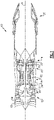
- FIG. 1 schematically illustrates a gas turbine engine 10.
- the gas turbine engine 10 is disclosed herein as a two-spool turbofan that generally incorporates a fan section 12, a compressor section 14, a combustor section 16, a turbine section 18, and a nozzle section 20.
- the sections are defined along a central longitudinal engine axis A.
- the compressor section 14, the combustor section 16, and the turbine section 18 are generally referred to as the engine core.
- the fan section 12 and a low pressure turbine 22 of the turbine section 18 are coupled by a first shaft 24 to define a low spool.
- the compressor section 14 and a high pressure turbine 26 of the turbine section 18 are coupled by a second shaft 28 to define a high spool.
- An outer engine case structure 30 and an inner engine structure 32 define a generally annular secondary flow path 34 around an inner flow path 36. It should be understood that various structure within the gas turbine engine 10 may define the outer engine case structure 30 and the inner engine structure 32 which essentially define an exoskeleton to support the core engine therein.
- Air which enters the fan section 12 is divided between an inner flow through the inner flow path 36 and a secondary or bypass flow through the secondary flow path 34.
- the inner flow passes through the compressor section 14, the combustor section 16, the turbine section 18, and then through the nozzle section 20.
- the secondary flow may be utilized for a multiple of purposes to include, for example, cooling and pressurization.
- the secondary flow as defined herein is any flow different from the primary combustion gas exhaust core flow.
- the secondary flow passes through an annulus defined by the outer engine case structure 30 and the inner engine structure 32 then may be at least partially injected into the core flow adjacent the nozzle section 20.
- the gas turbine engine 10 further includes a vane system 60 upstream of a fan 38 of the fan section 12.
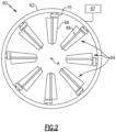
- FIG. 2 illustrates details of the vane system 60.
- Vane system 60 includes a synchronization ring 62 and a plurality of vane assemblies 64 arranged circumferentially about the engine central longitudinal axis A.
- Each vane assembly 64 includes an airfoil 66, a control rod 68 extending through the airfoil 66, and a bell-crank mechanism 70 driven by the synchronization ring 62.
- a controller 67 is configured to control actuation of the synchronization ring 62.
- the operation of the synchronization ring 62 may be as known. This disclosure relates to the operation of the bell-crank mechanism 70 to change the shape of airfoil 66.
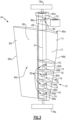
- FIG. 3 illustrates an example of one of the vane assemblies 64.
- the airfoil 66 includes a leading edge 66a and a trailing edge 66b downstream of the leading edge 66a.
- a strut portion 69 of the airfoil 66 extends from the leading edge 66a to the control rod 68.
- a variable flap portion 71 of the airfoil 66 is aft of the strut portion 69 and extends from the control rod 68 to the trailing edge 66b.
- the variable flap portion 71 includes a morphable structure 72 defined by a plurality of radial segments 74 interspaced by deformable supports 76.
- the airfoil 66 further includes a pressure side 66c and a suction side 66d positioned opposite the pressure side 66c and a flexible skin 77 surrounding the pressure side 66c and suction side 66d.
- the strut portion 69 and each radial segment 74 of the variable flap portion 71 in this example may be made of a rigid material such as metal, carbon fiber, or ceramic.
- the deformable supports 76 in this example are made of elastomer. Specifically, the deformable supports 76 may be polyurethane, isoprene, silicone, or fluoroelastomer.
- the airfoil 66 extends from a radially inner support hardware 78a to a radially outer support hardware 78b.
- Radially inner support hardware 78a may be mounted on a hub (not shown) of the fan section 12.
- Radially outer support hardware 78b may be mounted on bypass duct housing 15 (not shown).
- the radially inner and outer support hardware 78a/78b are configured to maintain the radial position of each vane assembly 64 within the fan section 12 while allowing the variable flap portion 71 of the airfoil 66 to pivot about an airfoil axis B.
- Activation of the synchronization ring 62 drives the bell-crank mechanism 70 of each vane assembly 64 to, in turn, cause the variable flap portion 71 of each vane assembly 64 to pivot about the airfoil axis B.
- the strut portion 69 remains fixed by support hardware 78a/78b when the bell-crank mechanism 70 actuates, and only the variable flap portion 71 pivots.
- strut portion 69 is not fixed such that the entire airfoil 66 pivots about axis B when the bell-crank mechanism 70 actuates.
- Control rod 68 is housed within airfoil 66 and is permitted to slide relative to the variable flap portion 71 in a radial direction about axis B. Control rod 68 is driven to radially translate through a control rod mechanism 80 driven by the rotating input of the bell-crank mechanism 70.
- the morphable structure 72 also includes a morphing mechanism 82 driven by translation of the control rod 68 to change the shape of the trailing edge 66b.
- the radial segments 74 of the variable flap portion 71 are non-continuous with one another and the strut portion 69, such that they may rotate or pivot independently about axis B.
- Morphing mechanism 82 converts the radial sliding movement of the control rod 68 into rotation or pivoting of the radial segments 74 about axis B relative to the leading edge 66a.
- Control rod mechanism 80 and morphing mechanism 82 in this example are cam mechanisms.
- the control rod mechanism 80 includes a protrusion 84a on the control rod 68 and a slot 86a configured to receive the protrusion 84a in the bell-crank mechanism 70.
- morphing mechanism 82 includes a plurality of protrusions 84b on the control rod 68 and each radial segment 74 includes a slot 86b/86c/86d/86e for receiving a protrusion 84b.
- the slots 86a/86b/86c/86d/86e are angled relative to the plane tangential to axis B.
- the angled slot 86a of control rod mechanism 80 moves circumferentially about the control rod 68 and applies a radial force on protrusion 84a which slides within slot 86a and drives control rod 68 to translate along axis B.
- This translation of the control rod 68 translates the protrusions 84b which, in turn, slide within angled slots 86b/86c/86d/86e and apply a force to angled slots 86b/86c/86d/86e which drives the radial segments 74 to rotate about axis B.
- protrusions 84a/84b are disclosed on the control rod 68 and the slots 86a/86b/86c/86d/86e are disclosed on the bell-crank mechanism 70 and radial segments 74, slot(s) 86a/86b/86c/86d/86e could be located on the control rod 68 with protrusions 84a/84b located on the bell-crank mechanism 70 and/or the radial segments 74.
- Morphing mechanism 82 is tailorable with respect to each radial segment 74, such that for a given degree of rotational input from the bell-crank mechanism 70, each radial segment 74 can pivot by a different desired amount about axis B to tailor the shape of the trailing edge 66b. This may be accomplished by adjusting the angles of slots 86a/86b/86c/86d/86e relative to the plane tangent to axis B. Each of the angled slots 86b/86c/86d/86e are indicated as distinct components to make clear that each slot may have a different angle.
- the deformable supports 76 interspace and connect the radial segments 74, and are deformable such that radial segments 74 maintain a connection as they pivot about axis B.
- the deformable supports 76 and the flexible skin 77 provide the airfoil with a smooth external body around the pressure side 66c and suction side 66d.
- the flexible skin 77 surrounds both the strut portion 69 and the variable flap portion 71 of the airfoil 66, which includes surrounding the morphable structure 72. In other examples, the flexible skin 77 may only surround the variable flap portion 71 .
- Figure 4A illustrates a top view of vane assembly 64 where the radial segments 74 are in an initial aligned position. In this aligned position, the radial segments 74 are generally stacked directly atop one another and the deformable supports 76 interspacing the radial segments 74 are not deformed.
- Figure 4A further illustrates that the flexible skin 77 may be formed of layers 77a/77b/77c/77d of alternating elastomer and a relatively stiffer material, such as metal or polymer matrix composite.
- the introduction of elastomer layers within a composite or metal structure of the flexible skin 77 allows it to change to the desired shape of the airfoil 66 while still retaining stiffness to support pressure loads on the airfoil during operation.
- the elastomer layers 77a and 77c may be one of ethylene propylene diene monomer, synthetic rubber, and thermoplastic polyurethane, and may be thinner relative to the rigid layers 77c and 77d.
- the complete flexible skin 77 may be uniform without layers, and may be formed of one of the above listed elastomers or an appropriately flexible metal, such as titanium.
- Figure 4A also illustrates that the flexible skin 77 may be discontinuous between the pressure side 66c and the suction side 66d at the trailing edge 66b.
- This configuration allows flexible skin 77 on the pressure side 66c to slide relative to the suction side 66d when the trailing edge 66b changes shape. Allowing the flexible skin 77 to slide at the trailing edge 66b enables use of less flexible, but more robust, materials for the flexible skin 77, such as titanium.
- the flexible skin 77 can be continuous at both the leading edge 66a and trailing edge 66b and fully encapsulate the airfoil 66.
- FIG 4B illustrates a top view of vane assembly 64 (without deformable supports 76 or flexible skin 77 as shown) where the radial segments 74 have been driven into a morphed position.
- each radial segment 74 has a different angle ⁇ relative to the leading edge 66a and the deformable supports 76 deform to bridge the angular gap and maintain connection between each radial segment 74.
- the radial segments 74 are pivoted towards the pressure side 66c of the airfoil 66.
- the radial segments 74 may also be driven into an alternate morphed position where the radial segments 74 are pivoted towards the suction side 66d of the airfoil 66.
- each radial segment 74 may be illustrated to be greater than will be the actual case.
- the difference in angle ⁇ between each adjacent radial segments 74 is illustrated as approximately equal across the span, that may not be the case in practice.
- the airfoil 66 is illustrated as a symmetrical airfoil in the aligned position, i.e. one in which the airfoil 66 extends straight down from the top view without variations along its span.
- the airfoil 66 may extend straight down from the top view without variations along its span.
- there may be some camber or tailoring of the shape of the airfoil across its span in the aligned position and a deformed position that radial segments 74 are driven into may have less camber than the aligned position.
- activation of the bell-crank mechanism 70 effectuates both rotation of variable flap 71 about axis B and also changes the shape of the trailing edge 66b.
- Use of a single input beneficially reduces the number of components needed to accomplish the desired motion and shape change.
- vane assembly 64 allows an additional degree of freedom in tailoring both the orientation of variable flap 71 about axis B and tailoring of the shape of the variable flap 71 in the radial direction. This allows changing between more optimal shapes and orientation of airfoil 66 during operation for different operating conditions of the engine 10. This allows better conditioning of the air ingested by the fan during those operating conditions, leading to higher efficiency and/or improved stability.
- activation of the synchronization ring 62 by controller 67 drives the bell-crank mechanisms 70 of each of the plurality of vane assemblies 64 in unison.
- activation of the synchronization ring 62 causes each variable flap 71 to pivot about axis B and have its morphable structure 72 change shape axisymmetrically.
- the controller 67 may be an independent, stand-alone component, or part of a flight full authority digital engine controller (FADEC).
- the controller 67 is configured to actuate the synchronization ring 62 to pivot and morph variable flaps 71 in response to change in operating conditions of the engine 10.
- the controller 67 controls the synchronization ring to keep the variable flap portion 71 in the initial position illustrated in Figure 4A during cruise condition and the morphed position illustrated in Figure 4B may be utilized during idle or dash condition.
- the controller 67 may also activate the synchronization ring into intermediate positions between an initial and a fully morphed position during certain operating conditions, such as during idle or dash.
- controller 67 may utilize a morphed position in the direction of one of the pressure side 66c or suction side 66d during certain operating conditions, such as idle, and utilize an alternate morphed position in the opposite direction during other operating conditions, such as dash.
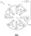
- Figure 5 illustrates another example vane system 160.
- like reference numerals designate like elements where appropriate and reference numerals with the addition of one-hundred or multiples thereof designate modified elements that are understood to incorporate the same features and benefits of the corresponding elements.
- first synchronization ring 162a and a second synchronization ring 162b there is a first synchronization ring 162a and a second synchronization ring 162b.
- the first and second synchronization rings 162a/162b each drive the bell-crank mechanisms 70 of a first and second group of vane assemblies 64a/64b respectively.
- the controller 67 is configured to control actuation of the first and second synchronization rings 162a/162b independently.
- the controller 67 can direct the first group of vane assemblies 64a to pivot and morph shape independently of the second group of vane assemblies 64b, and vice versa.
- two synchronization rings 162a/162b controlling two groups of vane assemblies 64a/64b are shown, one would understand that there could be additional synchronization rings controlling further subsets of vane assemblies.
- FIG. 6 illustrates another example vane system 260.
- each bell-crank mechanism 70 of a plurality of vane assemblies 64 is driven by a separate actuator 88 which is controlled by controller 67.
- controller 67 can control each actuator 88 to drive each vane assembly 64 to pivot and change shape independent of every other vane assembly 64.
- the vane systems 160 and 260 illustrated in Figures 5 and 6 allow the vane assemblies 64 to be driven from axisymmetric configurations into non-axisymmetric configurations. This is accomplished by driving individual or subgroups of vane assemblies 64 about the circumference of the vane systems 160/260 non-uniformly or at different schedules.
- the controller 67 may drive the vane systems 160/260 into non-axisymmetric configurations in response to non-axisymmetric fan inlet conditions, i.e. where air ingested by the fan section 12 is circumferentially non-uniform.
- These non-axisymmetric fan inlet conditions may be caused by the shape of the inlet delivering flow to the fan 38.
Landscapes
- Engineering & Computer Science (AREA)
- Chemical & Material Sciences (AREA)
- Mechanical Engineering (AREA)
- General Engineering & Computer Science (AREA)
- Combustion & Propulsion (AREA)
- Physics & Mathematics (AREA)
- Fluid Mechanics (AREA)
- Materials Engineering (AREA)
- Geometry (AREA)
- Structures Of Non-Positive Displacement Pumps (AREA)
Abstract
Description
- This application relates to a gas turbine engine with fan inlet variable vanes that may morph in shape.
- Gas turbine engines typically include a fan section, a compressor section, a combustor section, and a turbine section. Air entering the compressor section is compressed and delivered into the combustion section where it is mixed with fuel and ignited to generate a high-pressure and temperature exhaust gas flow. The high-pressure and temperature exhaust gas flow expands through the turbine section to drive the compressor section and the fan section. The compressor section may include low and high pressure compressors, and the turbine section may also include low and high pressure turbines.
- Fan inlet variable vanes may be included in the fan section upstream of the fan. The vanes turn air in a desired direction as it approaches the fan. However, the desired direction may change depending on the operating condition of the engine. As such, it is known to provide variable vanes. Variable vanes are typically provided with an actuator which deflects a flap on the trailing edge of the vanes such that the trailing edges change an incident angle relative to the angle of the fan blades depending on operating condition.
- In general, the vanes have changed the fan blade incident angle by deflection of a monolithic flap such that the angular change of the trailing edge is uniform across the span of the vane.
- According to a first aspect of the present invention, a gas turbine engine includes a fan section, a compressor section, and a turbine section. The fan section has a plurality of vane assemblies spaced circumferentially about an engine axis. The vane assemblies each include an airfoil extending between a leading edge and a trailing edge, a control rod extending through the airfoil, and a mechanism driven by the control rod to change the shape of the airfoil.
- In an embodiment according to the above, the mechanism changes the shape of the trailing edge.
- In another embodiment according to any of the above, the trailing edge includes a plurality of radial segments interspaced by deformable supports.
- In another embodiment according to any of the above, the radial segments are one of metal, carbon fiber, and ceramic. The deformable supports are one of polyurethane, isoprene, silicone, and fluoroelastomer.
- In another embodiment according to any of the above, the control rod drives the plurality of radial segments to pivot from an initial position to a morphed position in which the radial segments each have a different angle relative to the leading edge.
- In another embodiment according to any of the above, one of the control rod and the radial segments includes a plurality of protrusions and the other includes angled slots receiving the protrusions.
- In another embodiment according to any of the above, the control rod includes the plurality of protrusions and each radial segment includes an angled slot receiving a protrusion.
- In another embodiment according to any of the above, the control rod translates radially within the airfoil such that the protrusions slide within the angled slots driving the radial segments to pivot into the morphed position.
- In another embodiment according to any of the above, the vanes further include a flexible skin.
- In another embodiment according to any of the above, the flexible skin is comprised of one of ethylene propylene diene monomer, synthetic rubber, and thermoplastic polyurethane.
- In another embodiment according to any of the above, the airfoil includes a pressure side and a suction side. The flexible skin on the pressure side slides relative to the flexible skin on the suction side when the airfoil changes shape.
- In another embodiment according to any of the above, a single synchronization ring drives the control rod of each vane assembly to change the shape of each airfoil simultaneously.
- In another embodiment according to any of the above, a first and second synchronization ring drives control rods of a first and second subset of the plurality of vane assemblies respectively. The first and second synchronization rings drive the control rods to change the shape of the airfoils in the first and second subset independently.
- In another embodiment according to any of the above, the control rod of each of the plurality of vane assemblies is driven to rotate by a separate actuator to change the shape of each airfoil independently.
- In another embodiment according to any of the above, a controller controls actuation of the control rods. The controller actuates the control rods to change the shape of the airfoils in response to a change in operating conditions.
- In another embodiment according to any of the above, the controller controls actuation of at least one synchronization ring. The at least one synchronization ring drives the control rod of each of the vane assemblies and drives a flap portion of each airfoil to pivot about an airfoil axis.
- In another embodiment according to any of the above, the controller drives the plurality of vanes into a non-axisymmetric configuration in response to non-axisymmetric fan inlet conditions.
- According to a second aspect of the present invention, a gas turbine engine includes a fan section, a compressor section, and a turbine section. The compressor section has a plurality of vane assemblies spaced circumferentially about an engine axis. The vane assemblies each include an airfoil extending between a leading edge and a trailing edge, a control rod extending through the airfoil, and a mechanism driven by the control rod to change the shape of the airfoil.
- The gas turbine engine of the second aspect may comprise any of the features described above in relation to the first aspect.
- According to a third aspect of the present invention, a vane system for a gas turbine engine includes a plurality of vane assemblies spaced circumferentially about an engine axis. The vane assemblies each include an airfoil extending between a leading edge and a trailing edge. The trailing edge includes a plurality of radial segments interspaced by deformable supports, a control rod extending through the airfoil, and a mechanism driven by the control rod to change the shape of the trailing edge by driving the plurality of radial segments to pivot from an initial position to a morphed position in which the radial segments each have a different angle relative to the leading edge.
- In an embodiment according to the above, one of the control rod and the radial segments includes a plurality of protrusions and the other includes angled slots receiving the protrusions. The control rod translates radially within the airfoil such that the protrusions slide within the angled slots driving the radial segments into the morphed position.
- The present disclosure may include any one or more of the individual features disclosed above and/or below alone or in any combination thereof.
- These and other features of the present invention can be best understood from the following specification and drawings, the following of which is a brief description.
-
-
Figure 1 schematically shows a gas turbine engine. -
Figure 2 illustrates a vane system from the engine. -
Figure 3 illustrates details of a vane assembly from the vane system. -
Figure 4A illustrates a top view of the vane assembly in an initial position. -
Figure 4B illustrates a top view of the vane assembly in a morphed position. -
Figure 5 illustrates another example vane system with a plurality of synchronization rings. -
Figure 6 illustrates another example vane system with independent actuators. -
Figure 1 schematically illustrates agas turbine engine 10. Thegas turbine engine 10 is disclosed herein as a two-spool turbofan that generally incorporates a fan section 12, a compressor section 14, a combustor section 16, a turbine section 18, and a nozzle section 20. The sections are defined along a central longitudinal engine axis A. - The compressor section 14, the combustor section 16, and the turbine section 18 are generally referred to as the engine core. The fan section 12 and a
low pressure turbine 22 of the turbine section 18 are coupled by afirst shaft 24 to define a low spool. The compressor section 14 and ahigh pressure turbine 26 of the turbine section 18 are coupled by asecond shaft 28 to define a high spool. - An outer engine case structure 30 and an inner engine structure 32 define a generally annular secondary flow path 34 around an inner flow path 36. It should be understood that various structure within the
gas turbine engine 10 may define the outer engine case structure 30 and the inner engine structure 32 which essentially define an exoskeleton to support the core engine therein. - Air which enters the fan section 12 is divided between an inner flow through the inner flow path 36 and a secondary or bypass flow through the secondary flow path 34. The inner flow passes through the compressor section 14, the combustor section 16, the turbine section 18, and then through the nozzle section 20. The secondary flow may be utilized for a multiple of purposes to include, for example, cooling and pressurization. The secondary flow as defined herein is any flow different from the primary combustion gas exhaust core flow. The secondary flow passes through an annulus defined by the outer engine case structure 30 and the inner engine structure 32 then may be at least partially injected into the core flow adjacent the nozzle section 20.
- The
gas turbine engine 10 further includes avane system 60 upstream of afan 38 of the fan section 12. -
Figure 2 illustrates details of thevane system 60.Vane system 60 includes asynchronization ring 62 and a plurality ofvane assemblies 64 arranged circumferentially about the engine central longitudinal axis A. Eachvane assembly 64 includes anairfoil 66, acontrol rod 68 extending through theairfoil 66, and a bell-crank mechanism 70 driven by thesynchronization ring 62. Acontroller 67 is configured to control actuation of thesynchronization ring 62. - The operation of the
synchronization ring 62 may be as known. This disclosure relates to the operation of the bell-crank mechanism 70 to change the shape ofairfoil 66. -
Figure 3 illustrates an example of one of thevane assemblies 64. Theairfoil 66 includes aleading edge 66a and a trailingedge 66b downstream of theleading edge 66a. In this example, astrut portion 69 of theairfoil 66 extends from theleading edge 66a to thecontrol rod 68. Avariable flap portion 71 of theairfoil 66 is aft of thestrut portion 69 and extends from thecontrol rod 68 to the trailingedge 66b. Thevariable flap portion 71 includes amorphable structure 72 defined by a plurality ofradial segments 74 interspaced by deformable supports 76. Theairfoil 66 further includes apressure side 66c and asuction side 66d positioned opposite thepressure side 66c and aflexible skin 77 surrounding thepressure side 66c andsuction side 66d. - The
strut portion 69 and eachradial segment 74 of thevariable flap portion 71 in this example may be made of a rigid material such as metal, carbon fiber, or ceramic. The deformable supports 76 in this example are made of elastomer. Specifically, the deformable supports 76 may be polyurethane, isoprene, silicone, or fluoroelastomer. - The
airfoil 66 extends from a radiallyinner support hardware 78a to a radially outer support hardware 78b. Radiallyinner support hardware 78a may be mounted on a hub (not shown) of the fan section 12. Radially outer support hardware 78b may be mounted on bypass duct housing 15 (not shown). - Terms such as "radial," "inner," and "outer" refer to locations and orientations with respect to the central engine axis A. Moreover, the terminology "first" and "second" used herein is to differentiate that there are two architecturally distinct components or features. It is to be further understood that the terms "first" and "second" are interchangeable in that a first component or feature could alternatively be termed as the second component or feature, and vice versa.
- The radially inner and
outer support hardware 78a/78b are configured to maintain the radial position of eachvane assembly 64 within the fan section 12 while allowing thevariable flap portion 71 of theairfoil 66 to pivot about an airfoil axis B. Activation of thesynchronization ring 62 drives the bell-crank mechanism 70 of eachvane assembly 64 to, in turn, cause thevariable flap portion 71 of eachvane assembly 64 to pivot about the airfoil axis B. In this example, thestrut portion 69 remains fixed bysupport hardware 78a/78b when the bell-crank mechanism 70 actuates, and only thevariable flap portion 71 pivots. In other examples,strut portion 69 is not fixed such that theentire airfoil 66 pivots about axis B when the bell-crank mechanism 70 actuates. -
Control rod 68 is housed withinairfoil 66 and is permitted to slide relative to thevariable flap portion 71 in a radial direction about axisB. Control rod 68 is driven to radially translate through acontrol rod mechanism 80 driven by the rotating input of the bell-crank mechanism 70. - The
morphable structure 72 also includes a morphingmechanism 82 driven by translation of thecontrol rod 68 to change the shape of the trailingedge 66b. Theradial segments 74 of thevariable flap portion 71 are non-continuous with one another and thestrut portion 69, such that they may rotate or pivot independently about axisB. Morphing mechanism 82 converts the radial sliding movement of thecontrol rod 68 into rotation or pivoting of theradial segments 74 about axis B relative to theleading edge 66a. -
Control rod mechanism 80 and morphingmechanism 82 in this example are cam mechanisms. Thecontrol rod mechanism 80 includes aprotrusion 84a on thecontrol rod 68 and aslot 86a configured to receive theprotrusion 84a in the bell-crank mechanism 70. Similarly, morphingmechanism 82 includes a plurality ofprotrusions 84b on thecontrol rod 68 and eachradial segment 74 includes a slot 86b/86c/86d/86e for receiving aprotrusion 84b. Theslots 86a/86b/86c/86d/86e are angled relative to the plane tangential to axis B. In operation, when the bell-crank mechanism 70 actuates, theangled slot 86a ofcontrol rod mechanism 80 moves circumferentially about thecontrol rod 68 and applies a radial force onprotrusion 84a which slides withinslot 86a and drivescontrol rod 68 to translate along axis B. This translation of thecontrol rod 68 translates theprotrusions 84b which, in turn, slide within angled slots 86b/86c/86d/86e and apply a force to angled slots 86b/86c/86d/86e which drives theradial segments 74 to rotate about axis B. While theprotrusions 84a/84b are disclosed on thecontrol rod 68 and theslots 86a/86b/86c/86d/86e are disclosed on the bell-crank mechanism 70 andradial segments 74, slot(s) 86a/86b/86c/86d/86e could be located on thecontrol rod 68 withprotrusions 84a/84b located on the bell-crank mechanism 70 and/or theradial segments 74. - Morphing
mechanism 82 is tailorable with respect to eachradial segment 74, such that for a given degree of rotational input from the bell-crank mechanism 70, eachradial segment 74 can pivot by a different desired amount about axis B to tailor the shape of the trailingedge 66b. This may be accomplished by adjusting the angles ofslots 86a/86b/86c/86d/86e relative to the plane tangent to axis B. Each of the angled slots 86b/86c/86d/86e are indicated as distinct components to make clear that each slot may have a different angle. - The deformable supports 76 interspace and connect the
radial segments 74, and are deformable such thatradial segments 74 maintain a connection as they pivot about axis B. The deformable supports 76 and theflexible skin 77 provide the airfoil with a smooth external body around thepressure side 66c andsuction side 66d. In this example, theflexible skin 77 surrounds both thestrut portion 69 and thevariable flap portion 71 of theairfoil 66, which includes surrounding themorphable structure 72. In other examples, theflexible skin 77 may only surround thevariable flap portion 71 . -
Figure 4A illustrates a top view ofvane assembly 64 where theradial segments 74 are in an initial aligned position. In this aligned position, theradial segments 74 are generally stacked directly atop one another and thedeformable supports 76 interspacing theradial segments 74 are not deformed. -
Figure 4A further illustrates that theflexible skin 77 may be formed oflayers 77a/77b/77c/77d of alternating elastomer and a relatively stiffer material, such as metal or polymer matrix composite. The introduction of elastomer layers within a composite or metal structure of theflexible skin 77 allows it to change to the desired shape of theairfoil 66 while still retaining stiffness to support pressure loads on the airfoil during operation. The elastomer layers 77a and 77c may be one of ethylene propylene diene monomer, synthetic rubber, and thermoplastic polyurethane, and may be thinner relative to therigid layers 77c and 77d. Alternatively, the completeflexible skin 77 may be uniform without layers, and may be formed of one of the above listed elastomers or an appropriately flexible metal, such as titanium. -
Figure 4A also illustrates that theflexible skin 77 may be discontinuous between thepressure side 66c and thesuction side 66d at the trailingedge 66b. This configuration allowsflexible skin 77 on thepressure side 66c to slide relative to thesuction side 66d when the trailingedge 66b changes shape. Allowing theflexible skin 77 to slide at the trailingedge 66b enables use of less flexible, but more robust, materials for theflexible skin 77, such as titanium. Alternatively, theflexible skin 77 can be continuous at both theleading edge 66a and trailingedge 66b and fully encapsulate theairfoil 66. -
Figure 4B illustrates a top view of vane assembly 64 (withoutdeformable supports 76 orflexible skin 77 as shown) where theradial segments 74 have been driven into a morphed position. In this morphed position, eachradial segment 74 has a different angle α relative to theleading edge 66a and the deformable supports 76 deform to bridge the angular gap and maintain connection between eachradial segment 74. In changing shape from the aligned position illustrated inFigure 4A to the morphed position inFigure 4B , theradial segments 74 are pivoted towards thepressure side 66c of theairfoil 66. However, theradial segments 74 may also be driven into an alternate morphed position where theradial segments 74 are pivoted towards thesuction side 66d of theairfoil 66. - To better illustrate the concept, the amount of difference between the angles α of each
radial segment 74 may be illustrated to be greater than will be the actual case. Similarly, although the difference in angle α between each adjacentradial segments 74 is illustrated as approximately equal across the span, that may not be the case in practice. - Referring back to
Figure 4A , theairfoil 66 is illustrated as a symmetrical airfoil in the aligned position, i.e. one in which theairfoil 66 extends straight down from the top view without variations along its span. However, there may be some camber or tailoring of the shape of the airfoil across its span in the aligned position and a deformed position thatradial segments 74 are driven into may have less camber than the aligned position. - Accordingly, activation of the bell-
crank mechanism 70 effectuates both rotation ofvariable flap 71 about axis B and also changes the shape of the trailingedge 66b. Use of a single input beneficially reduces the number of components needed to accomplish the desired motion and shape change. - Further, the configuration of
vane assembly 64 allows an additional degree of freedom in tailoring both the orientation ofvariable flap 71 about axis B and tailoring of the shape of thevariable flap 71 in the radial direction. This allows changing between more optimal shapes and orientation ofairfoil 66 during operation for different operating conditions of theengine 10. This allows better conditioning of the air ingested by the fan during those operating conditions, leading to higher efficiency and/or improved stability. - In the
example vane system 60 disclosed inFigures 2-4 , activation of thesynchronization ring 62 bycontroller 67 drives the bell-crankmechanisms 70 of each of the plurality ofvane assemblies 64 in unison. Thus, activation of thesynchronization ring 62 causes eachvariable flap 71 to pivot about axis B and have itsmorphable structure 72 change shape axisymmetrically. - The
controller 67 may be an independent, stand-alone component, or part of a flight full authority digital engine controller (FADEC). Thecontroller 67 is configured to actuate thesynchronization ring 62 to pivot and morphvariable flaps 71 in response to change in operating conditions of theengine 10. In this example, thecontroller 67 controls the synchronization ring to keep thevariable flap portion 71 in the initial position illustrated inFigure 4A during cruise condition and the morphed position illustrated inFigure 4B may be utilized during idle or dash condition. Thecontroller 67 may also activate the synchronization ring into intermediate positions between an initial and a fully morphed position during certain operating conditions, such as during idle or dash. Additionally,controller 67 may utilize a morphed position in the direction of one of thepressure side 66c orsuction side 66d during certain operating conditions, such as idle, and utilize an alternate morphed position in the opposite direction during other operating conditions, such as dash. -
Figure 5 illustrates anotherexample vane system 160. In this disclosure, like reference numerals designate like elements where appropriate and reference numerals with the addition of one-hundred or multiples thereof designate modified elements that are understood to incorporate the same features and benefits of the corresponding elements. - In the
vane system 160, there is afirst synchronization ring 162a and asecond synchronization ring 162b. The first andsecond synchronization rings 162a/162b each drive the bell-crankmechanisms 70 of a first and second group ofvane assemblies 64a/64b respectively. Thecontroller 67 is configured to control actuation of the first andsecond synchronization rings 162a/162b independently. Thus, thecontroller 67 can direct the first group ofvane assemblies 64a to pivot and morph shape independently of the second group ofvane assemblies 64b, and vice versa. Although twosynchronization rings 162a/162b controlling two groups ofvane assemblies 64a/64b are shown, one would understand that there could be additional synchronization rings controlling further subsets of vane assemblies. -
Figure 6 illustrates anotherexample vane system 260. In thevane system 260, each bell-crankmechanism 70 of a plurality ofvane assemblies 64 is driven by aseparate actuator 88 which is controlled bycontroller 67. Thus,controller 67 can control each actuator 88 to drive eachvane assembly 64 to pivot and change shape independent of everyother vane assembly 64. - The
vane systems Figures 5 and6 allow thevane assemblies 64 to be driven from axisymmetric configurations into non-axisymmetric configurations. This is accomplished by driving individual or subgroups ofvane assemblies 64 about the circumference of thevane systems 160/260 non-uniformly or at different schedules. Thecontroller 67 may drive thevane systems 160/260 into non-axisymmetric configurations in response to non-axisymmetric fan inlet conditions, i.e. where air ingested by the fan section 12 is circumferentially non-uniform. These non-axisymmetric fan inlet conditions may be caused by the shape of the inlet delivering flow to thefan 38. Different inlet configurations introduce different non-axisymmetric distortion to the face of thefan 38 which may also vary between operating conditions of theengine 10. Accordingly, the non-axisymmetric control offered byvane systems 160/260 allow circumferential tailoring of the vanes to address this varying distortion between operating conditions. - Although embodiments of this disclosure have been shown, a worker of ordinary skill in this art would recognize that modifications would come within the scope of this disclosure. For example, although the
vane system 60 is shown and described with reference to one location in the fan section 12 ofengine 10, it is to be understood that the examples herein are also applicable to structural vanes in other locations in fan section 12 and other sections of theengine 10, such as in vanes 37 of the compressor section 14. This disclosure is also beneficial in other engine configurations, including high-bypass turbofan engines. Further, although themorphable structure 72 is defined in this example with reference to the trailingedge 66b, one would understand that such a configuration could also be beneficially applied to theleading edge 66a of theairfoil 66. For that reason, the following claims should be studied to determine the true scope and content of this disclosure.
Claims (15)
- A gas turbine engine (10) comprising a fan section (12), a compressor section (14), and a turbine section (18), said fan section (12) or compressor section (14) having a plurality of vane assemblies (64) spaced circumferentially about an engine axis (A), the vane assemblies (64) each including:an airfoil (66) extending between a leading edge (66a) and a trailing edge (66b);a control rod (68) extending through the airfoil (66); anda mechanism driven by the control rod (68) to change the shape of the airfoil.
- The gas turbine engine (10) of claim 1, wherein the mechanism changes the shape of the trailing edge (66b).
- The gas turbine engine (10) of claim 1 or 2, wherein the trailing edge (66b) comprises a plurality of radial segments (74) interspaced by deformable supports (76), optionally wherein the radial segments (74) are metal, carbon fiber, or ceramic, and the deformable supports are polyurethane, isoprene, silicone, or fluoroelastomer.
- The gas turbine engine (10) of claim 3, wherein the control rod (68) drives the plurality of radial segments (74) to pivot from an initial position to a morphed position in which the radial segments (74) each define an angle relative to the leading edge (66a), and the angle of each radial segment is different to that of the others.
- The gas turbine engine (10) of claim 3 or 4, wherein the control rod (68) or the radial segments (74) includes a plurality of protrusions (84a-e) and the other includes angled slots (86a-e) receiving the protrusions (84a-e), optionally wherein the control rod (68) includes the plurality of protrusions (84a-e) and each radial segment (74) includes an angled slot (84a-e) receiving a protrusion (84a-e).
- The gas turbine engine (10) of claim 3 to 5, wherein the control rod (68) translates radially within the airfoil (66) such that the protrusions (84a-e) slide within the angled slots (86a-e) driving the radial segments (74) to pivot into the morphed position.
- The gas turbine engine (10) of any preceding claim, wherein the vanes (64) further include a flexible skin (77).
- The gas turbine engine (10) of claim 7, wherein the flexible skin (77) is comprised of one of ethylene propylene diene monomer, synthetic rubber, or thermoplastic polyurethane.
- The gas turbine engine (10) of claim 9 and 10, wherein the airfoil (66) includes a pressure side (66c) and a suction side (66d) and the flexible skin (77) on the pressure side (66c) slides relative to the flexible skin (77) on the suction side (66d) when the airfoil (66) changes shape.
- The gas turbine engine (10) of any preceding claim, further including a single synchronization ring (62) that drives the control rod (68) of each vane assembly (64) to change the shape of each airfoil (66) simultaneously.
- The gas turbine engine (10) of claims 1 to 9, further comprising first and second synchronization rings (162a, 162b) driving control rods (68) of a first and second subset of the plurality of vane assemblies respectively (64a, 64b), wherein the first and second synchronization rings (162a, 162d) drive the control rods (68) to change the shape of the airfoils (66) in the first and second subset independently.
- The gas turbine engine (10) of any preceding claim, further comprising a controller (67) controlling actuation of the control rods (68), the controller (67) actuating the control rods (68) to change the shape of the airfoils (66) in response to a change in operating conditions, and optionally wherein the controller (67) controls actuation of a or the at least one synchronization ring (62), the at least one synchronization ring (62) driving the control rod (68) of each of the vane assemblies (64) and driving a flap portion (71) of each airfoil (66) to pivot about an airfoil axis (B).
- The gas turbine engine (10) of claims 1 to 9, wherein the control rod (68) of each of the plurality of vane assemblies (64) is driven by a separate actuator (88) to change the shape of each airfoil (66) independently, and optionally further comprising a controller (67) controlling actuation of the control rods (68), the controller (67) actuating the control rods (68) to change the shape of the airfoils (66) in response to a change in operating conditions.
- The gas turbine engine (10) of claim 12 or 13, wherein the controller (64) drives the plurality of vane assemblies (64) into a non-axisymmetric configuration in response to non-axisymmetric fan inlet conditions.
- A vane system for a gas turbine engine (10) comprising a plurality of vane assemblies (64) spaced circumferentially about an engine axis (A), the vane assemblies (64) each including:an airfoil (66) extending between a leading edge (66a) and a trailing edge (66b), the trailing edge (66b) comprising a plurality of radial segments (74) interspaced by deformable supports (76);a control rod (68) extending through the airfoil (66); anda mechanism (70) driven by the control rod (68) to change the shape of the trailing edge (66b) by driving the plurality of radial segments (74) to pivot from an initial position to a morphed position in which the radial segments (74) each have a different angle relative to the leading edge (66a), and optionally wherein one of the control rod (68) and the radial segments (74) includes a plurality of protrusions (84a-e) and the other includes angled slots (86a-e) receiving the protrusions (84a-e), and the control rod (68) translates radially within the airfoil (66) such that the protrusions slide (84a-e) within the angled slots (86a-e) driving the radial segments (74) into the morphed position.
Priority Applications (1)
| Application Number | Priority Date | Filing Date | Title |
|---|---|---|---|
| EP26153072.9A EP4726214A2 (en) | 2021-08-06 | 2022-07-18 | Morphing structures for adjustable fan inlet guide vanes |
Applications Claiming Priority (1)
| Application Number | Priority Date | Filing Date | Title |
|---|---|---|---|
| US17/396,050 US11655778B2 (en) | 2021-08-06 | 2021-08-06 | Morphing structures for fan inlet variable vanes |
Related Child Applications (1)
| Application Number | Title | Priority Date | Filing Date |
|---|---|---|---|
| EP26153072.9A Division EP4726214A2 (en) | 2021-08-06 | 2022-07-18 | Morphing structures for adjustable fan inlet guide vanes |
Publications (2)
| Publication Number | Publication Date |
|---|---|
| EP4130428A1 true EP4130428A1 (en) | 2023-02-08 |
| EP4130428B1 EP4130428B1 (en) | 2026-01-21 |
Family
ID=84833857
Family Applications (2)
| Application Number | Title | Priority Date | Filing Date |
|---|---|---|---|
| EP22185566.1A Active EP4130428B1 (en) | 2021-08-06 | 2022-07-18 | Morphing structures for adjustable fan inlet guide vanes |
| EP26153072.9A Pending EP4726214A2 (en) | 2021-08-06 | 2022-07-18 | Morphing structures for adjustable fan inlet guide vanes |
Family Applications After (1)
| Application Number | Title | Priority Date | Filing Date |
|---|---|---|---|
| EP26153072.9A Pending EP4726214A2 (en) | 2021-08-06 | 2022-07-18 | Morphing structures for adjustable fan inlet guide vanes |
Country Status (2)
| Country | Link |
|---|---|
| US (2) | US11655778B2 (en) |
| EP (2) | EP4130428B1 (en) |
Families Citing this family (6)
| Publication number | Priority date | Publication date | Assignee | Title |
|---|---|---|---|---|
| US12428973B2 (en) * | 2023-12-22 | 2025-09-30 | Ge Infrastructure Technology Llc | Mitigation of rotating stall in turbine exhaust section using segmented auxiliary struts |
| US12286888B1 (en) * | 2023-12-22 | 2025-04-29 | Ge Infrastructure Technology Llc | Mitigation of rotating stall in turbine section using outer flow control vanes |
| US12203385B1 (en) | 2024-02-02 | 2025-01-21 | Rtx Corporation | Telescoping guide vane for aircraft propulsion system |
| US12352287B1 (en) * | 2024-03-25 | 2025-07-08 | Rtx Corporation | Variable guide vane for aircraft propulsion system |
| US12467384B1 (en) | 2024-11-15 | 2025-11-11 | Rtx Corporation | Translatable guide vanes for aircraft propulsion system |
| CN120845134A (en) * | 2025-09-25 | 2025-10-28 | 四川工程职业技术大学 | A blade structure with stepless airfoil camber controllable and control method thereof |
Citations (8)
| Publication number | Priority date | Publication date | Assignee | Title |
|---|---|---|---|---|
| US3237918A (en) * | 1963-08-30 | 1966-03-01 | Gen Electric | Variable stator vanes |
| US3295827A (en) * | 1966-04-06 | 1967-01-03 | Gen Motors Corp | Variable configuration blade |
| US20080317587A1 (en) * | 2007-06-20 | 2008-12-25 | Lord Wesley K | Variable-shape variable-stagger inlet guide vane flap |
| US20150159501A1 (en) * | 2013-06-03 | 2015-06-11 | United Technologies Corporation | Rigid and Rotatable Vanes Molded Within Variably Shaped Flexible Airfoils |
| US20150361819A1 (en) * | 2014-01-24 | 2015-12-17 | United Technologies Corporation | Virtual multi-stream gas turbine engine |
| US20180371938A1 (en) * | 2017-06-23 | 2018-12-27 | Rolls-Royce North American Technologies Inc. | Method and Configuration for Improved Variable Vane Positioning |
| EP3502416A1 (en) * | 2017-12-19 | 2019-06-26 | United Technologies Corporation | Inlet guide vane and corresponding gas turbine engine |
| EP3670849A1 (en) * | 2018-12-17 | 2020-06-24 | United Technologies Corporation | Variable vane assemblies configured for non-axisymmetric actuation |
Family Cites Families (24)
| Publication number | Priority date | Publication date | Assignee | Title |
|---|---|---|---|---|
| US3397836A (en) * | 1967-01-03 | 1968-08-20 | Gen Motors Corp | Flexible vane and variable vane cascades |
| DE3540401A1 (en) * | 1985-11-14 | 1987-05-21 | Mtu Muenchen Gmbh | Vane ring for turbo machines, especially for gas turbines |
| GB8722714D0 (en) * | 1987-09-26 | 1987-11-04 | Rolls Royce Plc | Variable guide vane arrangement for compressor |
| US5114104A (en) * | 1990-10-01 | 1992-05-19 | The United States Of America As Represented By The Secretary Of The Navy | Articulated control surface |
| DE19742314C2 (en) * | 1997-09-25 | 2000-06-21 | Daimler Chrysler Ag | Supporting structure |
| DE19852944C1 (en) * | 1998-11-17 | 2000-02-10 | Daimler Chrysler Ag | Variable geometry wing profile has flexible construction for the leading and trailing edges operated by integral actuators |
| EP1603798B1 (en) * | 2003-03-03 | 2010-10-20 | Flexsys, Inc. | Adaptive compliant wing and rotor system |
| US7550189B1 (en) * | 2004-08-13 | 2009-06-23 | Hrl Laboratories, Llc | Variable stiffness structure |
| GB0519502D0 (en) | 2005-09-24 | 2005-11-02 | Rolls Royce Plc | Vane assembly |
| DE102005061751B4 (en) * | 2005-12-21 | 2013-09-19 | Eurocopter Deutschland Gmbh | Rotor blade for a rotary wing aircraft |
| US8967945B2 (en) * | 2007-05-22 | 2015-03-03 | United Technologies Corporation | Individual inlet guide vane control for tip turbine engine |
| US8418967B2 (en) * | 2008-02-21 | 2013-04-16 | Cornerstone Research Group, Inc. | Passive adaptive structures |
| GB0916787D0 (en) * | 2009-09-24 | 2009-11-04 | Rolls Royce Plc | Variable shape rotor blade |
| US10125724B2 (en) * | 2012-01-17 | 2018-11-13 | United Technologies Corporation | Start system for gas turbine engines |
| US9145198B1 (en) * | 2013-01-04 | 2015-09-29 | The Boeing Company | Variable camber airfoil system |
| US10563593B2 (en) * | 2016-01-04 | 2020-02-18 | Rolls-Royce North American Technologies, Inc. | System and method of transferring power in a gas turbine engine |
| EP3232008A1 (en) | 2016-04-13 | 2017-10-18 | Rolls-Royce plc | Aerofoil body |
| US20180216527A1 (en) * | 2017-01-27 | 2018-08-02 | General Electric Company | Radial variable inlet guide vane for axial or axi-centrifugal compressors |
| US10273976B2 (en) | 2017-02-03 | 2019-04-30 | General Electric Company | Actively morphable vane |
| US10774674B2 (en) * | 2018-09-13 | 2020-09-15 | Raytheon Technologies Corporation | Set screw gap control between fixed and variable vanes |
| US11028725B2 (en) | 2018-12-13 | 2021-06-08 | Raytheon Technologies Corporation | Adaptive morphing engine geometry |
| US11092030B2 (en) | 2019-04-18 | 2021-08-17 | Raytheon Technologies Corporation | Adaptive case for a gas turbine engine |
| US11111811B2 (en) | 2019-07-02 | 2021-09-07 | Raytheon Technologies Corporation | Gas turbine engine with morphing variable compressor vanes |
| US11041404B2 (en) | 2019-11-04 | 2021-06-22 | Raytheon Technologies Corporation | In-situ wireless monitoring of engine bearings |
-
2021
- 2021-08-06 US US17/396,050 patent/US11655778B2/en active Active
-
2022
- 2022-07-18 EP EP22185566.1A patent/EP4130428B1/en active Active
- 2022-07-18 EP EP26153072.9A patent/EP4726214A2/en active Pending
-
2023
- 2023-02-23 US US18/113,139 patent/US12247529B2/en active Active
Patent Citations (8)
| Publication number | Priority date | Publication date | Assignee | Title |
|---|---|---|---|---|
| US3237918A (en) * | 1963-08-30 | 1966-03-01 | Gen Electric | Variable stator vanes |
| US3295827A (en) * | 1966-04-06 | 1967-01-03 | Gen Motors Corp | Variable configuration blade |
| US20080317587A1 (en) * | 2007-06-20 | 2008-12-25 | Lord Wesley K | Variable-shape variable-stagger inlet guide vane flap |
| US20150159501A1 (en) * | 2013-06-03 | 2015-06-11 | United Technologies Corporation | Rigid and Rotatable Vanes Molded Within Variably Shaped Flexible Airfoils |
| US20150361819A1 (en) * | 2014-01-24 | 2015-12-17 | United Technologies Corporation | Virtual multi-stream gas turbine engine |
| US20180371938A1 (en) * | 2017-06-23 | 2018-12-27 | Rolls-Royce North American Technologies Inc. | Method and Configuration for Improved Variable Vane Positioning |
| EP3502416A1 (en) * | 2017-12-19 | 2019-06-26 | United Technologies Corporation | Inlet guide vane and corresponding gas turbine engine |
| EP3670849A1 (en) * | 2018-12-17 | 2020-06-24 | United Technologies Corporation | Variable vane assemblies configured for non-axisymmetric actuation |
Also Published As
| Publication number | Publication date |
|---|---|
| US20230193855A1 (en) | 2023-06-22 |
| EP4130428B1 (en) | 2026-01-21 |
| US20230044195A1 (en) | 2023-02-09 |
| EP4726214A2 (en) | 2026-04-15 |
| US12247529B2 (en) | 2025-03-11 |
| US11655778B2 (en) | 2023-05-23 |
Similar Documents
| Publication | Publication Date | Title |
|---|---|---|
| EP4726214A2 (en) | Morphing structures for adjustable fan inlet guide vanes | |
| US7942632B2 (en) | Variable-shape variable-stagger inlet guide vane flap | |
| EP2071135B1 (en) | 3D Contoured vane endwall for variable area turbine vane arrangement | |
| US9957823B2 (en) | Virtual multi-stream gas turbine engine | |
| EP1122407B1 (en) | Controllable guide vane apparatus for a gas turbine engine | |
| US8459035B2 (en) | Gas turbine engine with low fan pressure ratio | |
| EP2504552B1 (en) | Variable area fan nozzle with a bearing track | |
| US10060285B2 (en) | Variable vane control system | |
| EP2984315B1 (en) | Annular airflow actuation system for variable cycle gas turbine engines | |
| US20120124964A1 (en) | Gas turbine engine with improved fuel efficiency | |
| US11111811B2 (en) | Gas turbine engine with morphing variable compressor vanes | |
| US20090067978A1 (en) | Variable area turbine vane arrangement | |
| EP2798183B1 (en) | Gas turbine engine with low fan pressure ratio | |
| EP2074321A2 (en) | Fan variable area nozzle with adaptive structure | |
| WO2013106223A1 (en) | Gas turbine engine with geared architecture | |
| EP4006315B1 (en) | Variable orientation guide vane for a gas turbine engine, and method of operating adjacent variable orientation first and second vanes disposed in an annular gas path of a gas turbine engine | |
| US20150192298A1 (en) | Gas turbine engine with improved fuel efficiency | |
| US10648359B2 (en) | System for controlling variable-setting blades for a turbine engine | |
| EP2115289B1 (en) | Gas turbine engine with fan variable area nozzle having rotating overlapping tabs | |
| US20150132106A1 (en) | Gas turbine engine with low fan pressure ratio | |
| EP3043033A1 (en) | Gas turbine engine with improved fuel efficiency | |
| EP3728816B1 (en) | Compressor control | |
| CN120303467A (en) | Three-channel aircraft turbine | |
| WO2013154639A2 (en) | Gas turbine engine with improved fuel efficiency | |
| EP3048266A1 (en) | Gas turbine engine with low fan pressure ratio |
Legal Events
| Date | Code | Title | Description |
|---|---|---|---|
| PUAI | Public reference made under article 153(3) epc to a published international application that has entered the european phase |
Free format text: ORIGINAL CODE: 0009012 |
|
| STAA | Information on the status of an ep patent application or granted ep patent |
Free format text: STATUS: THE APPLICATION HAS BEEN PUBLISHED |
|
| AK | Designated contracting states |
Kind code of ref document: A1 Designated state(s): AL AT BE BG CH CY CZ DE DK EE ES FI FR GB GR HR HU IE IS IT LI LT LU LV MC MK MT NL NO PL PT RO RS SE SI SK SM TR |
|
| STAA | Information on the status of an ep patent application or granted ep patent |
Free format text: STATUS: REQUEST FOR EXAMINATION WAS MADE |
|
| 17P | Request for examination filed |
Effective date: 20230808 |
|
| RBV | Designated contracting states (corrected) |
Designated state(s): AL AT BE BG CH CY CZ DE DK EE ES FI FR GB GR HR HU IE IS IT LI LT LU LV MC MK MT NL NO PL PT RO RS SE SI SK SM TR |
|
| RAP3 | Party data changed (applicant data changed or rights of an application transferred) |
Owner name: RTX CORPORATION |
|
| STAA | Information on the status of an ep patent application or granted ep patent |
Free format text: STATUS: EXAMINATION IS IN PROGRESS |
|
| 17Q | First examination report despatched |
Effective date: 20241205 |
|
| GRAP | Despatch of communication of intention to grant a patent |
Free format text: ORIGINAL CODE: EPIDOSNIGR1 |
|
| STAA | Information on the status of an ep patent application or granted ep patent |
Free format text: STATUS: GRANT OF PATENT IS INTENDED |
|
| INTG | Intention to grant announced |
Effective date: 20250807 |
|
| GRAS | Grant fee paid |
Free format text: ORIGINAL CODE: EPIDOSNIGR3 |
|
| GRAA | (expected) grant |
Free format text: ORIGINAL CODE: 0009210 |
|
| STAA | Information on the status of an ep patent application or granted ep patent |
Free format text: STATUS: THE PATENT HAS BEEN GRANTED |
|
| AK | Designated contracting states |
Kind code of ref document: B1 Designated state(s): AL AT BE BG CH CY CZ DE DK EE ES FI FR GB GR HR HU IE IS IT LI LT LU LV MC MK MT NL NO PL PT RO RS SE SI SK SM TR |
|
| REG | Reference to a national code |
Ref country code: CH Ref legal event code: F10 Free format text: ST27 STATUS EVENT CODE: U-0-0-F10-F00 (AS PROVIDED BY THE NATIONAL OFFICE) Effective date: 20260121 |
|
| REG | Reference to a national code |
Ref country code: DE Ref legal event code: R096 Ref document number: 602022028744 Country of ref document: DE |
|
| REG | Reference to a national code |
Ref country code: IE Ref legal event code: FG4D |