EP4130339A1 - Manganese-iridium complex oxide for water decomposition catalyst, manganese-iridium complex oxide electrode material, and production methods therefor - Google Patents
Manganese-iridium complex oxide for water decomposition catalyst, manganese-iridium complex oxide electrode material, and production methods therefor Download PDFInfo
- Publication number
- EP4130339A1 EP4130339A1 EP21774005.9A EP21774005A EP4130339A1 EP 4130339 A1 EP4130339 A1 EP 4130339A1 EP 21774005 A EP21774005 A EP 21774005A EP 4130339 A1 EP4130339 A1 EP 4130339A1
- Authority
- EP
- European Patent Office
- Prior art keywords
- manganese
- composite oxide
- iridium
- electrode material
- iridium composite
- Prior art date
- Legal status (The legal status is an assumption and is not a legal conclusion. Google has not performed a legal analysis and makes no representation as to the accuracy of the status listed.)
- Granted
Links
Images



Classifications
-
- C—CHEMISTRY; METALLURGY
- C25—ELECTROLYTIC OR ELECTROPHORETIC PROCESSES; APPARATUS THEREFOR
- C25B—ELECTROLYTIC OR ELECTROPHORETIC PROCESSES FOR THE PRODUCTION OF COMPOUNDS OR NON-METALS; APPARATUS THEREFOR
- C25B11/00—Electrodes; Manufacture thereof not otherwise provided for
- C25B11/04—Electrodes; Manufacture thereof not otherwise provided for characterised by the material
- C25B11/051—Electrodes formed of electrocatalysts on a substrate or carrier
- C25B11/073—Electrodes formed of electrocatalysts on a substrate or carrier characterised by the electrocatalyst material
- C25B11/075—Electrodes formed of electrocatalysts on a substrate or carrier characterised by the electrocatalyst material consisting of a single catalytic element or catalytic compound
-
- C—CHEMISTRY; METALLURGY
- C01—INORGANIC CHEMISTRY
- C01G—COMPOUNDS CONTAINING METALS NOT COVERED BY SUBCLASSES C01D OR C01F
- C01G55/00—Compounds of ruthenium, rhodium, palladium, osmium, iridium, or platinum
- C01G55/002—Compounds containing ruthenium, rhodium, palladium, osmium, iridium or platinum, with or without oxygen or hydrogen, and containing two or more other elements
-
- C—CHEMISTRY; METALLURGY
- C25—ELECTROLYTIC OR ELECTROPHORETIC PROCESSES; APPARATUS THEREFOR
- C25B—ELECTROLYTIC OR ELECTROPHORETIC PROCESSES FOR THE PRODUCTION OF COMPOUNDS OR NON-METALS; APPARATUS THEREFOR
- C25B1/00—Electrolytic production of inorganic compounds or non-metals
- C25B1/01—Products
- C25B1/02—Hydrogen or oxygen
- C25B1/04—Hydrogen or oxygen by electrolysis of water
-
- C—CHEMISTRY; METALLURGY
- C25—ELECTROLYTIC OR ELECTROPHORETIC PROCESSES; APPARATUS THEREFOR
- C25B—ELECTROLYTIC OR ELECTROPHORETIC PROCESSES FOR THE PRODUCTION OF COMPOUNDS OR NON-METALS; APPARATUS THEREFOR
- C25B11/00—Electrodes; Manufacture thereof not otherwise provided for
- C25B11/04—Electrodes; Manufacture thereof not otherwise provided for characterised by the material
- C25B11/051—Electrodes formed of electrocatalysts on a substrate or carrier
- C25B11/052—Electrodes comprising one or more electrocatalytic coatings on a substrate
-
- C—CHEMISTRY; METALLURGY
- C25—ELECTROLYTIC OR ELECTROPHORETIC PROCESSES; APPARATUS THEREFOR
- C25B—ELECTROLYTIC OR ELECTROPHORETIC PROCESSES FOR THE PRODUCTION OF COMPOUNDS OR NON-METALS; APPARATUS THEREFOR
- C25B11/00—Electrodes; Manufacture thereof not otherwise provided for
- C25B11/04—Electrodes; Manufacture thereof not otherwise provided for characterised by the material
- C25B11/051—Electrodes formed of electrocatalysts on a substrate or carrier
- C25B11/055—Electrodes formed of electrocatalysts on a substrate or carrier characterised by the substrate or carrier material
- C25B11/056—Electrodes formed of electrocatalysts on a substrate or carrier characterised by the substrate or carrier material consisting of textile or non-woven fabric
-
- C—CHEMISTRY; METALLURGY
- C25—ELECTROLYTIC OR ELECTROPHORETIC PROCESSES; APPARATUS THEREFOR
- C25B—ELECTROLYTIC OR ELECTROPHORETIC PROCESSES FOR THE PRODUCTION OF COMPOUNDS OR NON-METALS; APPARATUS THEREFOR
- C25B11/00—Electrodes; Manufacture thereof not otherwise provided for
- C25B11/04—Electrodes; Manufacture thereof not otherwise provided for characterised by the material
- C25B11/051—Electrodes formed of electrocatalysts on a substrate or carrier
- C25B11/055—Electrodes formed of electrocatalysts on a substrate or carrier characterised by the substrate or carrier material
- C25B11/057—Electrodes formed of electrocatalysts on a substrate or carrier characterised by the substrate or carrier material consisting of a single element or compound
- C25B11/061—Metal or alloy
- C25B11/063—Valve metal, e.g. titanium
-
- C—CHEMISTRY; METALLURGY
- C25—ELECTROLYTIC OR ELECTROPHORETIC PROCESSES; APPARATUS THEREFOR
- C25B—ELECTROLYTIC OR ELECTROPHORETIC PROCESSES FOR THE PRODUCTION OF COMPOUNDS OR NON-METALS; APPARATUS THEREFOR
- C25B11/00—Electrodes; Manufacture thereof not otherwise provided for
- C25B11/04—Electrodes; Manufacture thereof not otherwise provided for characterised by the material
- C25B11/051—Electrodes formed of electrocatalysts on a substrate or carrier
- C25B11/055—Electrodes formed of electrocatalysts on a substrate or carrier characterised by the substrate or carrier material
- C25B11/057—Electrodes formed of electrocatalysts on a substrate or carrier characterised by the substrate or carrier material consisting of a single element or compound
- C25B11/065—Carbon
-
- C—CHEMISTRY; METALLURGY
- C25—ELECTROLYTIC OR ELECTROPHORETIC PROCESSES; APPARATUS THEREFOR
- C25B—ELECTROLYTIC OR ELECTROPHORETIC PROCESSES FOR THE PRODUCTION OF COMPOUNDS OR NON-METALS; APPARATUS THEREFOR
- C25B11/00—Electrodes; Manufacture thereof not otherwise provided for
- C25B11/04—Electrodes; Manufacture thereof not otherwise provided for characterised by the material
- C25B11/051—Electrodes formed of electrocatalysts on a substrate or carrier
- C25B11/073—Electrodes formed of electrocatalysts on a substrate or carrier characterised by the electrocatalyst material
- C25B11/091—Electrodes formed of electrocatalysts on a substrate or carrier characterised by the electrocatalyst material consisting of at least one catalytic element and at least one catalytic compound; consisting of two or more catalytic elements or catalytic compounds
- C25B11/093—Electrodes formed of electrocatalysts on a substrate or carrier characterised by the electrocatalyst material consisting of at least one catalytic element and at least one catalytic compound; consisting of two or more catalytic elements or catalytic compounds at least one noble metal or noble metal oxide and at least one non-noble metal oxide
-
- C—CHEMISTRY; METALLURGY
- C25—ELECTROLYTIC OR ELECTROPHORETIC PROCESSES; APPARATUS THEREFOR
- C25B—ELECTROLYTIC OR ELECTROPHORETIC PROCESSES FOR THE PRODUCTION OF COMPOUNDS OR NON-METALS; APPARATUS THEREFOR
- C25B9/00—Cells or assemblies of cells; Constructional parts of cells; Assemblies of constructional parts, e.g. electrode-diaphragm assemblies; Process-related cell features
- C25B9/17—Cells comprising dimensionally-stable non-movable electrodes; Assemblies of constructional parts thereof
- C25B9/19—Cells comprising dimensionally-stable non-movable electrodes; Assemblies of constructional parts thereof with diaphragms
- C25B9/23—Cells comprising dimensionally-stable non-movable electrodes; Assemblies of constructional parts thereof with diaphragms comprising ion-exchange membranes in or on which electrode material is embedded
-
- C—CHEMISTRY; METALLURGY
- C25—ELECTROLYTIC OR ELECTROPHORETIC PROCESSES; APPARATUS THEREFOR
- C25D—PROCESSES FOR THE ELECTROLYTIC OR ELECTROPHORETIC PRODUCTION OF COATINGS; ELECTROFORMING; APPARATUS THEREFOR
- C25D9/00—Electrolytic coating other than with metals
- C25D9/04—Electrolytic coating other than with metals with inorganic materials
- C25D9/08—Electrolytic coating other than with metals with inorganic materials by cathodic processes
-
- C—CHEMISTRY; METALLURGY
- C01—INORGANIC CHEMISTRY
- C01P—INDEXING SCHEME RELATING TO STRUCTURAL AND PHYSICAL ASPECTS OF SOLID INORGANIC COMPOUNDS
- C01P2002/00—Crystal-structural characteristics
- C01P2002/50—Solid solutions
- C01P2002/52—Solid solutions containing elements as dopants
-
- C—CHEMISTRY; METALLURGY
- C01—INORGANIC CHEMISTRY
- C01P—INDEXING SCHEME RELATING TO STRUCTURAL AND PHYSICAL ASPECTS OF SOLID INORGANIC COMPOUNDS
- C01P2002/00—Crystal-structural characteristics
- C01P2002/70—Crystal-structural characteristics defined by measured X-ray, neutron or electron diffraction data
- C01P2002/72—Crystal-structural characteristics defined by measured X-ray, neutron or electron diffraction data by d-values or two theta-values, e.g. as X-ray diagram
-
- C—CHEMISTRY; METALLURGY
- C01—INORGANIC CHEMISTRY
- C01P—INDEXING SCHEME RELATING TO STRUCTURAL AND PHYSICAL ASPECTS OF SOLID INORGANIC COMPOUNDS
- C01P2002/00—Crystal-structural characteristics
- C01P2002/70—Crystal-structural characteristics defined by measured X-ray, neutron or electron diffraction data
- C01P2002/77—Crystal-structural characteristics defined by measured X-ray, neutron or electron diffraction data by unit-cell parameters, atom positions or structure diagrams
-
- C—CHEMISTRY; METALLURGY
- C01—INORGANIC CHEMISTRY
- C01P—INDEXING SCHEME RELATING TO STRUCTURAL AND PHYSICAL ASPECTS OF SOLID INORGANIC COMPOUNDS
- C01P2004/00—Particle morphology
- C01P2004/01—Particle morphology depicted by an image
- C01P2004/03—Particle morphology depicted by an image obtained by SEM
-
- C—CHEMISTRY; METALLURGY
- C01—INORGANIC CHEMISTRY
- C01P—INDEXING SCHEME RELATING TO STRUCTURAL AND PHYSICAL ASPECTS OF SOLID INORGANIC COMPOUNDS
- C01P2006/00—Physical properties of inorganic compounds
- C01P2006/40—Electric properties
-
- Y—GENERAL TAGGING OF NEW TECHNOLOGICAL DEVELOPMENTS; GENERAL TAGGING OF CROSS-SECTIONAL TECHNOLOGIES SPANNING OVER SEVERAL SECTIONS OF THE IPC; TECHNICAL SUBJECTS COVERED BY FORMER USPC CROSS-REFERENCE ART COLLECTIONS [XRACs] AND DIGESTS
- Y02—TECHNOLOGIES OR APPLICATIONS FOR MITIGATION OR ADAPTATION AGAINST CLIMATE CHANGE
- Y02E—REDUCTION OF GREENHOUSE GAS [GHG] EMISSIONS, RELATED TO ENERGY GENERATION, TRANSMISSION OR DISTRIBUTION
- Y02E60/00—Enabling technologies; Technologies with a potential or indirect contribution to GHG emissions mitigation
- Y02E60/30—Hydrogen technology
- Y02E60/36—Hydrogen production from non-carbon containing sources, e.g. by water electrolysis
Definitions
- the present invention relates to a manganese-iridium composite oxide for a water splitting catalyst, a manganese-iridium composite oxide electrode material, and their production methods and their applications. More particularly, the present invention relates to a manganese-iridium composite oxide and a manganese-iridium composite oxide electrode material, used as an anode catalyst for oxygen evolution in industrial water electrolysis conducted under alkaline conditions, under neutral conditions or under acidic conditions, or in water electrolysis using a polymer electrolyte membrane (PEM) type electrolytic cell, and their production methods.
- PEM polymer electrolyte membrane
- Water electrolysis method is one of useful means to produce high purity hydrogen gas from a cathode by electrolyzing water and is characterized by oxygen evolution from an anode as the counter electrode at the same time.
- the water splitting reaction efficiently proceeds in the water electrolysis method, it is necessary to conduct electrolysis while the electrolysis voltage applied through the electrolysis is kept low, using an electrode catalyst with a low hydrogen overvoltage for the cathode and an electrode catalyst with a low oxygen overvoltage for the anode.
- Non-Patent Documents 1 and 2 Non-Patent Documents 1 to 3.
- the catalyst materials constituted by transition metals proposed are problematic in that their activity is very low (the oxygen overvoltage is high) as compared with platinum group metal type electrode catalysts. That is, an oxygen evolution electrode catalyst material which is constituted by an inexpensive transition metal and which has a high catalytic activity comparable to platinum group metals such as Pt and Ir has not yet been realized.
- the object of the present invention is to provide a manganese-iridium composite oxide for a water splitting catalyst, a manganese-iridium composite oxide electrode material, and their production methods.
- a manganese-iridium composite oxide for a water splitting catalyst (hereinafter sometimes referred to as the manganese-iridium composite oxide of the present invention) which is used as an anode catalyst material for oxygen evolution in industrial water electrolysis conducted under alkaline conditions, under neutral conditions or under acidic conditions or in water electrolysis using a polymer electrolyte membrane (PEM) type electrolytic cell, which is available at a low cost and which has high oxygen evolution catalytic activity, a manganese-iridium composite oxide electrode material for a water splitting catalyst, and their production methods.
- PEM polymer electrolyte membrane
- the present inventors have conducted extensive studies on catalyst materials used as an oxygen evolution electrode catalyst in water electrolysis and as a result, found that a manganese-iridium composite oxide, which has an iridium metal content ratio (iridium/(manganese + iridium)) of 0.1 atomic% or more and 30 atomic% or less, and has interplanar spacings of at least 0.243 ⁇ 0.002 nm, 0.214 ⁇ 0.002 nm, 0.165 ⁇ 0.002 nm and 0.140 ⁇ 0.002 nm, has high oxygen evolution electrode catalytic activity, and accomplished the present invention.
- a manganese-iridium composite oxide which has an iridium metal content ratio (iridium/(manganese + iridium)) of 0.1 atomic% or more and 30 atomic% or less, and has interplanar spacings of at least 0.243 ⁇ 0.002 nm, 0.214 ⁇ 0.002 nm, 0.165 ⁇ 0.002 nm and 0.140 ⁇ 0.002 nm, has high oxygen
- the present invention provides a manganese-iridium composite oxide for an oxygen evolution electrode catalyst in water electrolysis, which has an iridium metal content ratio (iridium/(manganese + iridium)) of 0.1 atomic% or more and 30 atomic% or less, and has interplanar spacings of at least 0.243 ⁇ 0.002 nm, 0.214 ⁇ 0.002 nm, 0.165 ⁇ 0.002 nm and 0.140 ⁇ 0.002 nm.
- iridium metal content ratio iridium/(manganese + iridium)
- a manganese-iridium composite oxide electrode material comprising fibers of an electrically conductive substrate, at least part of which are covered with the manganese-iridium composite oxide of the present invention, has particularly high oxygen evolution electrode catalytic activity. That is, the present invention provides a manganese-iridium composite oxide electrode material for an oxygen evolution electrode, which comprises an electrically conductive substrate constituted by fibers at least part of which are covered with the manganese-iridium composite oxide of the present invention.
- the manganese-iridium composite oxide of the present invention and the manganese-iridium composite oxide electrode material of the present invention have high activity and function as an inexpensive and excellent anode catalyst for oxygen evolution, in industrial water electrolysis conducted under alkaline conditions, under neutral conditions or under acidic conditions, and in water electrolysis using a PEM type electrolytic cell. Further, the manganese-iridium composite oxide and the manganese-iridium composite oxide electrode material of the present invention have very excellent durability as an oxygen evolution electrode catalyst.
- hydrocarbon compounds such as formic acid, formaldehyde, methanol, methane, ethane and propane
- the oxygen evolution reaction in the Formula 2 is generally considered as the rate-determining step in the whole reaction, and development of a catalyst which can promote the reaction with a minimum energy is considered to be important in this technical field.
- the present invention is to provide an oxygen evolution electrode catalyst which has high water splitting catalytic performance.
- the manganese-iridium composite oxide of the present invention has an iridium metal content ratio (iridium/(manganese + iridium)) controlled to be 0.1 atomic% or more and 30 atomic% or less. If the iridium metal content ratio is less than 0.1 atomic%, its properties will be at a level of those of manganese oxide single catalyst, and if the iridium metal content ratio is higher than 30 atomic%, catalytic activity at a level of that of an iridium oxide will be achieved, however, since a rare element iridium is used in a large amount, the composite oxide will be very expensive, thus impairing the economical efficiency.
- iridium metal content ratio iridium/(manganese + iridium)
- the iridium metal content ratio is preferably 0.2 atomic% or more and 27 atomic% or less, more preferably 0.2 atomic% or more and 20 atomic% or less, further preferably 0.3 atomic% or more and 10.5 atomic% or less, particularly preferably 1 atomic% or more and 7 atomic% or less.
- the XRD of the manganese-iridium composite oxide of the present invention has characteristic diffraction lines.
- the diffraction pattern has, in order from the low angle side, at least diffraction lines which provide d representing the interplanar spacings of 0.243 ⁇ 0.002 nm, 0.214 ⁇ 0.002 nm, 0.165 ⁇ 0.002 nm and 0.140 ⁇ 0.002 nm.
- a manganese-iridium composite oxide having such interplanar spacings has not been reported yet, and the manganese-iridium composite oxide of the present invention shows X-ray diffraction patterns similar to those of ⁇ -manganese dioxide containing a large amount of structural faults by formation of microtwins.
- the manganese-iridium composite oxide of the present invention functions as the oxygen evolution electrode active material in water electrolysis and can impart the catalytic performance for the water splitting reaction to the oxygen evolution electrode.
- a polymer electrolyte membrane and an electrode having a hydrogen evolution catalyst By laminating the oxygen evolution electrode containing the oxygen evolution electrode active material, a polymer electrolyte membrane and an electrode having a hydrogen evolution catalyst, a laminate is obtained.
- the polymer electrolyte membrane may, for example, be a fluororesin type cation exchange membrane
- the hydrogen evolution catalyst may, for example, be platinum fine particles.
- a water electrolysis apparatus can be constituted, and by water electrolysis using the oxygen evolution electrode, hydrogen can be produced.
- the manganese-iridium composite oxide of the present invention may be produced by electrodeposition, for example, using as an electrolytic solution a sulfuric acid/manganese sulfate/iridium salt mixed solution. Otherwise, it may be produced by electrodepositing a manganese oxide using a sulfuric acid/manganese sulfate mixed solution and then electrodepositing an iridium oxide on the manganese oxide using a sulfuric acid/iridium salt mixed solution.
- the sulfuric acid concentration is adjusted to be preferably higher than 4 g/L and 65 g/L or less, more preferably 20 g/L or more and 50 g/L or less.
- the manganese concentration of the mixed solution is not particularly limited so long as it is the solubility or less, and is preferably 5 g/L or more and 50 g/L or less, more preferably 10 g/L or more and 30 g/L or less.
- the iridium concentration of the mixed solution is also not particularly limited so long as it is the solubility or less, and is preferably 0.1 g/L or more and 10 g/L or less, more preferably 0.3 g/L or more and 5 g/L or less.
- the ratio of the iridium concentration to the manganese concentration in the mixed solution influences the metal composition of the manganese-iridium composite oxide deposited by electrolytic oxidation, and thus it is preferably 0.002 or more and 0.05 or less, more preferably 0.005 or more and 0.02 or less, by the iridium/manganese molar ratio of the mixed solution.
- the sulfuric acid concentration in the sulfuric acid/manganese sulfate/iridium salt mixed solution, the sulfuric acid/manganese sulfate mixed solution and the sulfuric acid/iridium salt mixed solution is a value excluding bivalent anions (sulfate ions) of the manganese sulfate.
- the electrolysis current density is not particularly limited and is preferably 0.2 A/dm 2 or more and 0.9 A/dm 2 or less, whereby the manganese-iridium composite oxide of the present invention can readily be produced by electrolysis efficiently and stably.
- the electrolysis current density is more preferably 0.3 A/dm 2 or more and 0.88 A/dm 2 or less, further preferably 0.5 A/dm 2 or more and 0.8 A/dm 2 or less.
- the electrolysis temperature may, for example, be 93°C or more and 98°C or less.
- the manganese-iridium composite oxide formed on an electrode such as a pure titanium plate by electrolysis is separated from the electrode and roughly crushed e.g. by a jaw crusher, and ground and adjusted to have a predetermined average secondary particle size as a manganese-iridium composite oxide simple substance e.g. by a roller mill, a vertical mill, a Loesche mill or a jet mill. Then, the produced manganese oxide is subjected to a washing step and a neutralizing step, to remove the remaining electrolytic solution and then dried e.g. by a flash drying apparatus.
- a submicron-level manganese-iridium composite oxide fine powder formed as by-product by overgrinding in the grinding step may be recovered and separated by a bag filter of a dust collector. Further, a firing step at a temperature of 200°C or more and 500°C or less may be conducted to obtain the manganese-iridium composite oxide of the present invention.
- the manganese-iridium composite oxide electrode material of the present invention comprises an electrically conductive substrate constituted by fibers at least part of which are covered with the manganese-iridium composite oxide of the present invention.
- the amount of the covering manganese-iridium composite oxide of the present invention is, per geometric area of the electrically conductive substrate, preferably 0.1 mg/cm 2 or more and 25 mg/cm 2 or less.
- the geometric area corresponds to the projected area of the electrically conductive substrate, and the thickness of the substrate is not considered.
- the fibers can be covered with the manganese oxide in an islands form or substantially the whole outer surface of the fibers can be covered, depending on the diameter and the porosity of the fibers constituting the electrically conductive substrate, and the average covering thickness can be adjusted to be approximately at most 25 ⁇ m. Since the manganese-iridium composite oxide covering the fibers is constituted by secondary particles, usually, the average covering thickness and the average secondary particle size of the manganese-iridium composite oxide constituting the covering agree with each other.
- the average thickness of the manganese-iridium composite oxide covering the fibers of the electrically conductive substrate increases.
- the amount of the covering manganese-iridium composite oxide is preferably 0.1 mg/cm 2 or more and 20 mg/cm 2 or less, further preferably 0.2 mg/cm 2 or more and 15 mg/cm 2 or less, particularly preferably 0.5 mg/cm 2 or more and 12 mg/cm 2 or less.
- the thickness of the manganese-iridium composite oxide covering layer may be obtained also by, for example, subtracting the diameter of an electrically conductive fiber as a unit constituting the electrically conductive substrate, from a scanning electron microscope (SEM) image.
- the manganese-iridium composite oxide electrode material of the present invention may be obtained by electrodepositing a manganese-iridium composite oxide using the above sulfuric acid/manganese sulfate/iridium salt mixed solution, on an electrically conductive substrate represented by carbon paper, titanium mesh or platinum-covered titanium mesh, instead of the electrode substrate of the pure titanium plate.
- the manganese-iridium composite oxide is electrodeposited in a deposition amount of 0.1 mg/cm 2 or more and 25 mg/cm 2 or less per geometric area.
- the deposition amount of the manganese-iridium composite oxide tends to be too small, and the composite oxide may not sufficiently be attached to the substrate and will readily be separated, or the catalyst amount tends to be too small to sufficiently exhibit performance. If it is more than 25 mg/cm 2 , the manganese-iridium composite oxide covering layer tends to be too thick and electron transfer to the electrically conductive substrate may be impaired, or the gap between the electrically conductive fibers of the electrically conductive substrate tends to be small, and the transfer of water and oxygen which is a reaction product is limited thus becoming the rate-determining step, and thus the catalytic performance may not sufficiently be exhibited.
- the electrically conductive substrate is preferably one, for example, obtained by forming or sintering electrically conductive fibers of e.g. carbon or titanium having a diameter of 100 ⁇ m or less, into a plate shape having a thickness of 1 mm or less.
- the porosity of the electrically conductive substrate is, for example, preferably 40% or more, more preferably from 50 to 90%. The porosity is defined by the volume of spaces without electrically conductive fibers and the like in the volume of the electrically conductive substrate.
- electrodeposition may be conducted selecting the respective ranges of the sulfuric acid concentration, the manganese concentration and the iridium concentration of the sulfuric acid/manganese sulfate/iridium salt mixed solution, the sulfuric acid/manganese sulfate mixed solution and the sulfuric acid/iridium salt mixed solution, the electrolysis current density, the electrolysis temperature and the like, for an electrolysis time of from 5 minutes to 120 minutes, and washing with water and drying are conducted after completion of the electrolysis, whereby the manganese-iridium composite oxide electrode material of the present invention is obtained.
- an electrodeposited film of the manganese-iridium composite oxide is preferentially formed only on one side, and the manganese-iridium composite oxide is not substantially electrodeposited on the other side, so that the manganese-iridium composite oxide can be made unevenly electrodeposited on purpose.
- the post treatment by acid immersion is carried out, for example, by immersing the manganese-iridium composite oxide electrode material in a 0.5 mol/L to 5 mol/L sulfuric acid for from 30 minutes to 2 hours, followed by washing with water and drying.
- the post treatment by heating is carried out, for example, by heating the manganese-iridium composite oxide composite electrode in air or nitrogen atmosphere at from 180°C to 500°C for from 30 minutes to 8 hours. Heating may be conducted in air or nitrogen atmosphere at from 180°C to 300°C for from 30 minutes to 2 hours, but is conducted preferably in air or nitrogen atmosphere at higher than 300°C and 500°C or less for more than 2 hours to 8 hours or less.
- a laminate By laminating the manganese-iridium composite oxide electrode material of the present invention, a polymer electrolyte membrane and an electrode having a hydrogen evolution catalyst, a laminate is obtained.
- a water electrolysis apparatus can be constituted, and by water electrolysis using the manganese-iridium composite oxide electrode material, hydrogen can be produced.
- Each of the sulfuric acid/manganese sulfate/iridium salt mixed solution, the sulfuric acid/manganese sulfate mixed solution and the sulfuric acid/iridium salt mixed solution was diluted, and the concentrations of the manganese element and the iridium element were quantitatively determined by ICP-AES (manufactured by PerkinElmer, Optima 8300).
- a common X-ray diffraction apparatus manufactured by Rigaku Corporation, Ultima IV
- diffraction lines of the manganese-iridium composite oxide and the manganese-iridium composite oxide electrode material were measured.
- the electrodeposition amount of the manganese-iridium composite oxide was measured in accordance with the following method.
- the weight (1) of the substrate (the electrode substrate of e.g. titanium or the electrically conductive substrate) was preliminarily measured by a balance, and after the electrodeposition, the weight (2) of the substrate having the manganese-iridium composite oxide electrodeposited was measured by a balance, and from the difference between the weight (1) and the weight (2) (weight (2)- weight (1)), the electrodeposition amount of the manganese-iridium composite oxide was obtained.
- Constitution of a PEM type electrolytic cell using an electrode material of the electrically conductive substrate having the manganese-iridium composite oxide catalyst deposited was carried out as follows. Using as a working electrode an electrode material (flat mesh shape: 3 cm ⁇ 3 cm), and as a catalyst for a counter electrode carbon supported 20 wt% platinum catalyst (20% Platinum on Vulcan XC-72, Item #PTC20-1, Fuel Cell Earth), the counter electrode was prepared by preparing an electrically conductive catalyst ink and applying it to carbon paper, followed by airdrying. As a polymer electrolyte membrane, a Nafion membrane (Nafion 117, manufactured by Sigma-Aldrich) was used.
- the polymer electrolyte membrane was cleaned and protonated (pre-treatment) by being boiled in 3% hydrogen peroxide aqueous solution, pure water, a 1M sulfuric acid aqueous solution and then pure water each for one hour. Then, the polymer electrolyte membrane was sandwiched between the catalyst-coated surfaces of the working electrode and the counter electrode and hotpressed using a hot pressing machine (A-010D, manufactured by FC-R&D) at 135°C with a clamping force of 600 kg for 10 minutes to prepare a membrane/electrolyte assembly (MEA).
- A-010D manufactured by FC-R&D
- the MEA had adhesion improved even at the time of electrolysis by means of two sheets of stainless mesh (#100), and was attached to a casing of a PEM type electrolytic cell 1 (3036, manufactured by FC-R&D) or a PEM type electrolytic cell 2 (WE-4S-RICW, manufactured by FC Development Co., Ltd.).
- a current-voltage curve was measured at an operation temperature of 25°C using a PEM type electrolytic cell 1 constituted by using an electrode material of an electrically conductive substrate having the manganese-iridium composite oxide deposited.
- a PEM type electrolytic cell 1 constituted by using an electrode material of an electrically conductive substrate having the manganese-iridium composite oxide deposited.
- two-electrode system using only the working electrode and the counter electrode was employed, and the voltage applied was gradually increased to measure the current-voltage curve. Pure water was supplied to the PEM type electrolytic cell.
- the voltage increase rate was 5 mV/s so that the voltage at which the current started to increase would readily be distinguished.
- a higher current at the same voltage indicates a higher oxygen electrode catalytic activity.
- a current-voltage curve was measured at an operation temperature of 25°C or 80°C using a PEM type electrolytic cell 2 constituted by using an electrode material of an electrically conductive substrate having the manganese-iridium composite oxide deposited.
- a PEM type electrolytic cell 2 constituted by using an electrode material of an electrically conductive substrate having the manganese-iridium composite oxide deposited.
- two-electrode system using only the working electrode and the counter electrode was employed, and the voltage applied was gradually increased to measure the current-voltage curve. Pure water was supplied to the PEM type electrolytic cell.
- the voltage increase rate was 5 mV/s so that the voltage at which the current started to increase would readily be distinguished.
- an electrolysis voltage was measured at an operation temperature of 80°C using a PEM type electrolytic cell 2 constituted by using an electrode material of an electrically conductive substrate having the manganese-iridium composite oxide deposited.
- a PEM type electrolytic cell 2 constituted by using an electrode material of an electrically conductive substrate having the manganese-iridium composite oxide deposited.
- two-electrode system using only the working electrode and the counter electrode was employed, and while the current density applied to between the electrodes was maintained at 0.5 A/cm 2 , a change of the electrolysis voltage with time was measured. Pure water was supplied to the PEM type electrolytic cell. A smaller change of the electrolysis voltage with time indicates a higher performance to keep the oxygen electrode catalytic activity stable, that is socalled durability.
- Electrolysis was conducted in an electrolytic cell containing a mixed solution of 35 g/L of sulfuric acid, 51.3 g/L of manganese sulfate and 2.0 g/L of potassium hexachloroiridate (K 2 IrCl 6 ), to electrodeposit a manganese-iridium composite oxide on a carbon paper (TGP-H-060, manufactured by Toray Industries, Inc.). Electrolysis was conducted at an electrolysis current density of 0.7 A/dm 2 at an electrolysis temperature of 95°C for 60 minutes. After completion of the electrolysis, the carbon paper was washed with water, air-dried and cut into a size of 3 cm ⁇ 3 cm to prepare an electrode material. The manganese-iridium composite oxide electrode material was subjected to compositional analysis and XRD measurement, and the results are shown in Table 1.
- a mixed solution was prepared and electrolysis was conducted in the same manner as in Example 1 except that the manganese sulfate concentration, the type of the iridium salt, the type of the substrate and the electrolysis temperature were as identified in Table 1, to electrodeposit a manganese-iridium composite oxide on a carbon paper (TGP-H-060, manufactured by Toray Industries, Inc.) or a platinum-covered Ti mesh (ADL-414302-5056, manufactured by FC Development Co., Ltd.). Electrolysis was conducted at an electrolysis current density of 0.7 A/dm 2 for 60 minutes. After completion of electrolysis, the carbon paper or the Ti mesh was washed with water, air-dried and cut into a size of 3 cm ⁇ 3 cm to prepare an electrode material. The obtained manganese-iridium composite oxide electrode materials were subjected to compositional analysis and XRD measurement, and the results are shown in the following Table 1 and Figs. 1 and 2 .
- Electrolysis was conducted in an electrolytic cell containing a mixed solution of 32 g/L of sulfuric acid and 75 g/L of manganese sulfate, to electrodeposit a manganese oxide on a carbon paper (TGP-H-060, manufactured by Toray Industries, Inc.). Electrolysis was conducted at an electrolysis current density of 0.68 A/dm 2 at an electrolysis temperature of 94°C for 16 minutes. After completion of the electrolysis, the carbon paper was washed with water, air-dried and cut into a size of 3 cm ⁇ 3 cm to prepare an electrode material. The manganese oxide electrode material was subjected to XRD measurement, and the results are shown in the following Table 1 and Figs. 1 and 2 .
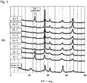
- the XRD patterns in Examples have substantially no diffraction line at 22 degrees excluding the diffraction line attributable to the carbon paper substrate, as compared with Comparative Example 1, and the other four principal diffraction lines shifted to the lower angle side.
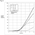
- the manganese oxide electrode material in Comparative Example 1 was used to constitute a PEM type electrolytic cell in accordance with ⁇ Constitution of PEM type electrolytic cell for evaluation of oxygen evolution electrode catalyst properties>, and the oxygen evolution electrode catalyst properties were evaluated in accordance with ⁇ Electrochemical measurement 1, measurement of current-voltage curve (PEM type electrolytic cell)> or ⁇ Electrochemical measurement 2, measurement of current-voltage curve (PEM type electrolytic cell 2)>, and the results are shown in the following Table 2 and Figs. 5 to 9 and Figs. 12 and 13 .
- a PEM type electrolytic cell was constituted by using an electrically conductive catalyst ink obtained by mixing a carbon supported 20 wt% platinum catalyst (20% Platinum on Vulcan XC-72, Item# PTC20-1, Fuel Cell Earth) and a diluted Nafion dispersion (10 wt% aqueous solution, 527106-25ML, manufactured by Sigma-Aldrich), and the oxygen evolution electrode catalyst properties were evaluated in accordance with ⁇ Electrochemical measurement 1, measurement of current-voltage curve (PEM type electrolytic cell)>. The results are shown in the following Table 2 and Fig. 5 .
- a PEM type electrolytic cell was constituted by using a commercial iridium oxide catalyst (manufactured by Elyst), and the oxygen evolution electrode catalyst properties were evaluated in accordance with ⁇ Electrochemical measurement 1, measurement of current-voltage curve (PEM type electrolytic cell)>, and the results are shown in the following Table 2 and Fig. 5 .
- Electrolysis was conducted in an electrolytic cell containing a mixed solution of 2.0 g/L of potassium hexachloroiridate (K 2 IrCl 6 ) in the same manner as in Example 1 except that the manganese sulfate concentration, the type of the iridium salt, the type of the substrate and the electrolysis temperature were as identified in Table 2, to electrodeposit a manganese-iridium composite oxide on a carbon paper (TGP-H-060, manufactured by Toray Industries, Inc.) or a platinum-covered Ti mesh (ADL-414302-5056, manufactured by FC Development Co., Ltd.). Electrolysis was conducted at an electrolysis current density of 0.7 A/dm 2 for 60 minutes.
- K 2 IrCl 6 potassium hexachloroiridate
- the electrode material was used to constitute a PEM type electrolytic cell in accordance with ⁇ Constitution of PEM type electrolytic cell for evaluation of oxygen evolution electrode catalyst properties>, and the oxygen evolution electrode catalyst properties were evaluated in accordance with ⁇ Electrochemical measurement 1, measurement of current-voltage curve (PEM type electrolytic cell 1)> or ⁇ Electrochemical measurement 2, measurement of current-voltage curve (PEM type electrolytic cell 2)>.
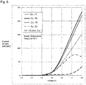
- the results are shown in the following Table 2 and Fig. 6 .
- Electrolysis was conducted in an electrolytic cell containing a mixed solution of 2.0 g/L of potassium hexachloroiridate (K 2 IrCl 6 ) in the same manner as in Example 1 except that the manganese sulfate concentration, the type of the iridium salt, the type of the substrate and the electrolysis temperature were as identified in Table 2, to electrodeposit a manganese-iridium composite oxide on a carbon paper (TGP-H-060, manufactured by Toray Industries, Inc.) or a platinum-covered Ti mesh (ADL-414302-5056, manufactured by FC Development Co., Ltd.). Electrolysis was conducted at an electrolysis current density of 0.7 A/dm 2 for 60 minutes.
- K 2 IrCl 6 potassium hexachloroiridate
- the carbon paper or the Ti mesh was washed with water, air-dried, subjected to annealing treatment at 230°C for 2 hours, and cut into a size of 3 cm ⁇ 3 cm to prepare an electrode material.
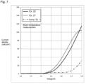
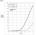
- the electrode material was used to constitute a PEM type electrolytic cell in accordance with ⁇ Constitution of PEM type electrolytic cell for evaluation of oxygen evolution electrode catalyst properties>, and the oxygen evolution electrode catalyst properties were evaluated in accordance with ⁇ Electrochemical measurement 2, measurement of current-voltage curve (PEM type electrolytic cell 2)>. The results are shown in the following Table 2 and Figs. 7 and 9 .
- Example 21 the electrode material in Example 21 was used to constitute a PEM type electrolytic cell in accordance with ⁇ Constitution of PEM type electrolytic cell for evaluation of oxygen evolution electrode catalyst properties>, and a change of the electrolysis voltage with time was measured in accordance with ⁇ Electrochemical measurement 3, measurement of electrolysis voltage stability (PEM type electrolytic cell 2)>. The results are shown in Fig. 10 .
- the manganese-iridium composite oxide and the manganese-iridium composite oxide electrode material of the present invention have a structure to achieve a high energy conversion efficiency in principle and exhibit high oxygen evolution electrode catalytic activity comparable to commercial iridium oxide catalysts even in a PEM type electrolytic cell for which use of a non-noble metal catalyst has been desired.
- Electrolysis conditions Composition of electrolytic solution Temperature Current density Type of substrate MnSO4 K2IrCl6 H2IrCl6 H2SO4 Ir/Mn ratio (g/L) (g/L) (g/L) (Molar ratio) (°C) (A/dm2) Ex. 1 51.9 2.0 0.0 35.0 0.012 95 0.7 CP Ex. 2 53.7 1.7 0.0 35.0 0.010 95 0.7 CP Ex.
- Electrolysis was conducted in an electrolytic cell containing a mixed solution of 35 g/L of sulfuric acid, 2.71 g/L of manganese sulfate and 0.48 g/L of potassium hexachloroiridate (K 2 IrCl 6 ) to electrodeposit a manganese-iridium composite oxide on a platinum covered Ti mesh (ADL-414302-5056, manufactured by FC Development Co., Ltd.). Electrolysis was conducted at 94°C at an electrolysis current density of 0.7 A/dm 2 for 60 minutes. After completion of electrolysis, the Ti mesh was washed with water, air-dried, subjected to heat treatment at 350°C for 5 hours, and cut into a size of 3 cm ⁇ 3 cm to prepare an electrode material. Using the obtained electrode material, a PEM type electrolytic cell was constituted in accordance with ⁇ Constitution of PEM type electrolytic cell for evaluation of oxygen evolution electrode catalyst properties>, and the oxygen evolution electrode catalyst properties were evaluated in accordance with
- Electrolysis was conducted in an electrolytic cell containing a mixed solution of 35 g/L of sulfuric acid and 54.4 g/L of manganese sulfate at 94°C at an electrolysis current density of 0.7 A/dm 2 for 10 minutes to electrodeposit a manganese oxide on a platinum covered Ti mesh (ADL-414302-5056, manufactured by FC Development Co., Ltd.).
- electrolysis was conducted in an electrolytic cell containing a mixed solution of 35 g/L of sulfuric acid and 0.16 g/L of potassium hexachloroiridate (K 2 IrCl 6 ) at 94°C at an electrolysis current density of 0.7 A/dm 2 for 60 minutes to electrodeposit an iridium oxide on the manganese oxide.
- the Ti mesh was washed with water, air-dried, subjected to heat treatment at 400°C for 5 hours, and then cut into a size of 3 cm ⁇ 3 cm to prepare an electrode material.
- the SEM photograph of the electrode material was shown in Fig. 11 .
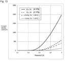
- a PEM type electrolytic cell was constituted in accordance with ⁇ Constitution of PEM type electrolytic cell for evaluation of oxygen evolution electrode catalyst properties>, and the oxygen evolution electrode catalyst properties were evaluated in accordance with
- the manganese-iridium composite oxide and the manganese-iridium composite oxide electrode material of the present invention have a structure to achieve a high energy conversion efficiency in principle, and exhibit particularly excellent oxygen evolution electrode catalytic activity by conducting appropriate heat treatment as a post treatment, and exhibit high oxygen evolution electrode catalytic activity comparable to commercial iridium oxide catalysts even in a PEM type electrolytic cell for which use of a non-noble metal catalyst has been desired.
- Electrolysis condition 1 Composition of electrolytic solution Temperature Current density Time MnSO4 K2IrCl6 H2IrCl6 H2SO4 Ir/Mn ratio (g/L) (g/L) (g/L) (Molar ratio) (°C) (A/dm2) (min) Ex. 23 2.71 0.48 0.00 35.0 0.056 94 0.7 60 Ex.
- Electrolysis condition 2 Heat treatment Composition of electrolytic solution Temperature Current density Time Temperature Time Gas MnSO4 K2IrCl6 H2IrCl6 H2SO4 Ir/Mn ratio (g/L) (g/L) (g/L) (Molar ratio) (°C) (A/dm2) (min) (°C) (min) Ex. 23 - - - - - - - - 350 300 Air Ex. 24 0.00 0.16 0.00 35.0 0.000 94 0.7 60 400 300 Air [Table 5] Properties of deposit Characteristic value (C.
- the manganese-iridium composite oxide and the manganese-iridium composite oxide electrode material of the present invention have high oxygen evolution electrode catalytic activity comparable to conventional noble metal type catalysts and accordingly when used as an anode catalyst for oxygen evolution in industrial water electrolysis conducted under alkaline or neutral conditions or in water electrolysis using a PEM type electrolytic cell, they are capable of producing hydrogen and oxygen at very low production costs.
- hydrocarbon compounds such as formic acid, formaldehyde, methanol, methane, ethane and propane
- hydrocarbon compounds such as formic acid, formaldehyde, methanol, methane, ethane and propane
Landscapes
- Chemical & Material Sciences (AREA)
- Organic Chemistry (AREA)
- Engineering & Computer Science (AREA)
- Chemical Kinetics & Catalysis (AREA)
- Electrochemistry (AREA)
- Materials Engineering (AREA)
- Metallurgy (AREA)
- Inorganic Chemistry (AREA)
- Electrodes For Compound Or Non-Metal Manufacture (AREA)
- Electrolytic Production Of Non-Metals, Compounds, Apparatuses Therefor (AREA)
- Catalysts (AREA)
Abstract
Description
- The present invention relates to a manganese-iridium composite oxide for a water splitting catalyst, a manganese-iridium composite oxide electrode material, and their production methods and their applications. More particularly, the present invention relates to a manganese-iridium composite oxide and a manganese-iridium composite oxide electrode material, used as an anode catalyst for oxygen evolution in industrial water electrolysis conducted under alkaline conditions, under neutral conditions or under acidic conditions, or in water electrolysis using a polymer electrolyte membrane (PEM) type electrolytic cell, and their production methods.
- From the viewpoint of depletion of fossil fuel and environmental pollution, utilization of hydrogen as a clean energy and its production process have attracted attention. Water electrolysis method is one of useful means to produce high purity hydrogen gas from a cathode by electrolyzing water and is characterized by oxygen evolution from an anode as the counter electrode at the same time. In order that the water splitting reaction efficiently proceeds in the water electrolysis method, it is necessary to conduct electrolysis while the electrolysis voltage applied through the electrolysis is kept low, using an electrode catalyst with a low hydrogen overvoltage for the cathode and an electrode catalyst with a low oxygen overvoltage for the anode. As an electrode catalyst material capable of providing excellent low oxygen overvoltage for the anode, compounds represented by rare platinum group metals such as platinum (Pt), iridium (Ir) and ruthenium (Ru), and oxides containing such elements, have been proposed (
Patent Documents Documents 1 to 3). - On the other hand, since an electrode catalyst constituted by such a platinum group metal is very expensive, development of an electrode catalyst using an inexpensive transition metal has been in progress. For example, in recent years, transition metal materials constituted by manganese (Mn), iron (Fe), cobalt (Co) or nickel (Ni) have been proposed (
Patent Documents Documents 4 to 7). - However, the catalyst materials constituted by transition metals proposed are problematic in that their activity is very low (the oxygen overvoltage is high) as compared with platinum group metal type electrode catalysts. That is, an oxygen evolution electrode catalyst material which is constituted by an inexpensive transition metal and which has a high catalytic activity comparable to platinum group metals such as Pt and Ir has not yet been realized.
- To solve such problems, a manganese oxide having oxygen evolution electrode catalytic activity equal to or greater than Pt has been found, but it does not achieve the activity comparable to Ir catalysts which are considered to have highest activity among platinum metal elements, and thus further development has been desired (Patent Document 5).
-
- Patent Document 1:
JP-A-H08-269761 - Patent Document 2:
JP-A-2007-514520 - Patent Document 3:
JP-A-2015-192993 - Patent Document 4:
WO2009/154753 - Patent Document 5:
WO2019/117199 -
- Non-Patent Document 1: S. Trasatti, G. Buzzanca, J. Electroanal. Chem., 1971, 29, A1.
- Non-Patent Document 2: A. Harriman, I. J. Pickering, J. M. Thomas, P. A. Christensen, J. Chem. Soc., Faraday Trans. 1, 1988, 84, 2795.
- Non-Patent Document 3: Y. Zhao, N. M. Vargas-Barbosa, E. A. Hernandez-Pagan, T. E. Mallouk, Small, 2011, 7, 2087.
- Non-Patent Document 4: M. M. Najafpour, G. Renger, M. Holynska, A. N. Moghaddam, E. -M. Aro, R. Carpentier, H. Nishihara, J. J. Eaton-Rye, J. -R. Shen, S. I. Allakhverdiev, Chem. Rev., 2016, 116, 2886.
- Non-Patent Document 5: T. Takashima, K. Ishikawa, H. Irie, J. Phys. Chem. C, 2016, 120, 24827.
- Non-Patent Document 6: J. B. Gerken, J. G. McAlpin, J. Y. C. Chen, M. L. Rigsby, W. H. Casey, R. D. Britt, S. S. Stahl, J. Am. Chem. Soc., 2011, 133, 14431.
- Non-Patent Document 7: M. Dinca, Y. Surendranath, D. G. Nocera, Proc. Natl. Acad. Sci. U.S.A., 2010, 107, 10337.
- The object of the present invention is to provide a manganese-iridium composite oxide for a water splitting catalyst, a manganese-iridium composite oxide electrode material, and their production methods.
- More particularly, it is to provide a manganese-iridium composite oxide for a water splitting catalyst (hereinafter sometimes referred to as the manganese-iridium composite oxide of the present invention) which is used as an anode catalyst material for oxygen evolution in industrial water electrolysis conducted under alkaline conditions, under neutral conditions or under acidic conditions or in water electrolysis using a polymer electrolyte membrane (PEM) type electrolytic cell, which is available at a low cost and which has high oxygen evolution catalytic activity, a manganese-iridium composite oxide electrode material for a water splitting catalyst, and their production methods.
- The present inventors have conducted extensive studies on catalyst materials used as an oxygen evolution electrode catalyst in water electrolysis and as a result, found that a manganese-iridium composite oxide, which has an iridium metal content ratio (iridium/(manganese + iridium)) of 0.1 atomic% or more and 30 atomic% or less, and has interplanar spacings of at least 0.243±0.002 nm, 0.214±0.002 nm, 0.165±0.002 nm and 0.140±0.002 nm, has high oxygen evolution electrode catalytic activity, and accomplished the present invention. That is, the present invention provides a manganese-iridium composite oxide for an oxygen evolution electrode catalyst in water electrolysis, which has an iridium metal content ratio (iridium/(manganese + iridium)) of 0.1 atomic% or more and 30 atomic% or less, and has interplanar spacings of at least 0.243±0.002 nm, 0.214±0.002 nm, 0.165±0.002 nm and 0.140±0.002 nm.
- The present inventors have further found that a manganese-iridium composite oxide electrode material comprising fibers of an electrically conductive substrate, at least part of which are covered with the manganese-iridium composite oxide of the present invention, has particularly high oxygen evolution electrode catalytic activity. That is, the present invention provides a manganese-iridium composite oxide electrode material for an oxygen evolution electrode, which comprises an electrically conductive substrate constituted by fibers at least part of which are covered with the manganese-iridium composite oxide of the present invention.
- The manganese-iridium composite oxide of the present invention and the manganese-iridium composite oxide electrode material of the present invention have high activity and function as an inexpensive and excellent anode catalyst for oxygen evolution, in industrial water electrolysis conducted under alkaline conditions, under neutral conditions or under acidic conditions, and in water electrolysis using a PEM type electrolytic cell. Further, the manganese-iridium composite oxide and the manganese-iridium composite oxide electrode material of the present invention have very excellent durability as an oxygen evolution electrode catalyst.
- Further, by adding carbon dioxide to the electrolysis system employing the manganese-iridium composite oxide electrode material of the present invention, carbon dioxide is reduced at the cathode, whereby hydrocarbon compounds (such as formic acid, formaldehyde, methanol, methane, ethane and propane) may be produced.
-
-
Fig. 1 is XRD patterns of the manganese-iridium composite oxides in Examples 2 to 9 and the manganese oxide in Comparative Example 1. -
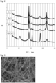
Fig. 2 is XRD patterns of the manganese-iridium composite oxides in Examples 10 to 12 and the manganese oxide in Comparative Example 1. -
Fig. 3 is a SEM photograph of a carbon paper (CP) substrate. -
Fig. 4 is a SEM photograph of the manganese-iridium composite oxide deposited on the carbon paper (CP) substrate in Example 12. -
Fig. 5 is linear sweep voltammograms illustrating the relation between the current and the potential (voltage) measured by using <PEM typeelectrolytic cell 1> at the time of evolution of oxygen (at the time of water electrolysis) in Examples 13 to 16 and Comparative Examples 1 to 3. -
Fig. 6 is linear sweep voltammograms illustrating the relation between the current and the potential (voltage) measured by using <PEM typeelectrolytic cell 1> at the time of evolution of oxygen (at the time of water electrolysis) in Examples 17 to 20 and Comparative Example 1. -
Fig. 7 is linear sweep voltammograms illustrating the relation between the current and the potential (voltage) measured by using <PEM typeelectrolytic cell 1> at the time of evolution of oxygen (at the time of water electrolysis) in Examples 21 and 22 and Comparative Example 1. -
Fig. 8 is linear sweep voltammograms illustrating the relation between the current and the potential (voltage) measured by using <PEM typeelectrolytic cell 1> at the time of evolution of oxygen (at the time of water electrolysis) in Examples 18 to 20 and Comparative Example 1. -
Fig. 9 is linear sweep voltammograms illustrating the relation between the current and the potential (voltage) measured by using <PEM typeelectrolytic cell 1> at the time of evolution of oxygen (at the time of water electrolysis) in Example 22 and Comparative Example 1. -
Fig. 10 is data illustrating the electrolysis voltage relative to time measured by using <PEM typeelectrolytic cell 2> at 80°C at 0.5 A/cm2 at the time of evolution of oxygen (at the time of water electrolysis) in Example 21. -
Fig. 11 is a SEM photograph of the manganese-iridium composite oxide deposited on the platinum-covered Ti mesh substrate in Example 24. -
Fig. 12 is linear sweep voltammograms illustrating the relation between the current and the potential (voltage) measured by using <PEM typeelectrolytic cell 2> at the time of evolution of oxygen (at the time of water electrolysis) in Example 23 and Comparative Example 1. -
Fig. 13 is linear sweep voltammograms illustrating the relation between the current and the potential (voltage) measured by using <PEM typeelectrolytic cell 2> at the time of evolution of oxygen (at the time of water electrolysis) in Example 24 and Comparative Example 1. - Now, the present invention will be described in further detail.
- First, decomposition of water by electrolysis will be described with reference to a reaction in which the reaction site is in an acidic environment, such as PEM type water electrolysis, as an example. On the cathode catalyst, hydrogen is formed by a reaction of two protons and two electrons as shown in
Formula 1.
2H+ + 2e- → H2 Formula 1
- On the other hand, on the anode catalyst, oxygen is formed together with four electrons and four protons from two water molecules, as shown in
Formula 2.
2H2O → O2 + 4H+ + 4e-Formula 2
- And, as a whole, a reaction by which two hydrogen molecules and one oxygen molecule are formed from two water molecules occurs, as shown in
Formula 3.
2H2O → 2H2 + O2 Formula 3
- The oxygen evolution reaction in the
Formula 2 is generally considered as the rate-determining step in the whole reaction, and development of a catalyst which can promote the reaction with a minimum energy is considered to be important in this technical field. The present invention is to provide an oxygen evolution electrode catalyst which has high water splitting catalytic performance. - The manganese-iridium composite oxide of the present invention has an iridium metal content ratio (iridium/(manganese + iridium)) controlled to be 0.1 atomic% or more and 30 atomic% or less. If the iridium metal content ratio is less than 0.1 atomic%, its properties will be at a level of those of manganese oxide single catalyst, and if the iridium metal content ratio is higher than 30 atomic%, catalytic activity at a level of that of an iridium oxide will be achieved, however, since a rare element iridium is used in a large amount, the composite oxide will be very expensive, thus impairing the economical efficiency. In order to achieve excellent properties, the iridium metal content ratio is preferably 0.2 atomic% or more and 27 atomic% or less, more preferably 0.2 atomic% or more and 20 atomic% or less, further preferably 0.3 atomic% or more and 10.5 atomic% or less, particularly preferably 1 atomic% or more and 7 atomic% or less.
- The XRD of the manganese-iridium composite oxide of the present invention has characteristic diffraction lines. The diffraction pattern has, in order from the low angle side, at least diffraction lines which provide d representing the interplanar spacings of 0.243±0.002 nm, 0.214±0.002 nm, 0.165±0.002 nm and 0.140±0.002 nm.
- A manganese-iridium composite oxide having such interplanar spacings has not been reported yet, and the manganese-iridium composite oxide of the present invention shows X-ray diffraction patterns similar to those of ε-manganese dioxide containing a large amount of structural faults by formation of microtwins.
- By making the manganese-iridium composite oxide of the present invention be supported on the electrode, the manganese-iridium composite oxide of the present invention functions as the oxygen evolution electrode active material in water electrolysis and can impart the catalytic performance for the water splitting reaction to the oxygen evolution electrode. By laminating the oxygen evolution electrode containing the oxygen evolution electrode active material, a polymer electrolyte membrane and an electrode having a hydrogen evolution catalyst, a laminate is obtained. The polymer electrolyte membrane may, for example, be a fluororesin type cation exchange membrane, and the hydrogen evolution catalyst may, for example, be platinum fine particles. In the present invention, by the oxygen evolution electrode, a water electrolysis apparatus can be constituted, and by water electrolysis using the oxygen evolution electrode, hydrogen can be produced.
- Now, the method for producing the manganese-iridium composite oxide of the present invention will be described.
- The manganese-iridium composite oxide of the present invention may be produced by electrodeposition, for example, using as an electrolytic solution a sulfuric acid/manganese sulfate/iridium salt mixed solution. Otherwise, it may be produced by electrodepositing a manganese oxide using a sulfuric acid/manganese sulfate mixed solution and then electrodepositing an iridium oxide on the manganese oxide using a sulfuric acid/iridium salt mixed solution.
- With respect to the concentrations of the components in the sulfuric acid/manganese sulfate/iridium salt mixed solution, the sulfuric acid/manganese sulfate mixed solution and the sulfuric acid/iridium salt mixed solution, the sulfuric acid concentration is adjusted to be preferably higher than 4 g/L and 65 g/L or less, more preferably 20 g/L or more and 50 g/L or less.
- The manganese concentration of the mixed solution is not particularly limited so long as it is the solubility or less, and is preferably 5 g/L or more and 50 g/L or less, more preferably 10 g/L or more and 30 g/L or less. The iridium concentration of the mixed solution is also not particularly limited so long as it is the solubility or less, and is preferably 0.1 g/L or more and 10 g/L or less, more preferably 0.3 g/L or more and 5 g/L or less. The ratio of the iridium concentration to the manganese concentration in the mixed solution influences the metal composition of the manganese-iridium composite oxide deposited by electrolytic oxidation, and thus it is preferably 0.002 or more and 0.05 or less, more preferably 0.005 or more and 0.02 or less, by the iridium/manganese molar ratio of the mixed solution.
- To maintain the concentrations of the components in the mixed solution, it is effective to properly add manganese sulfate and an iridium salt corresponding to the manganese and the iridium consumed by electrolytic oxidation, or to continuously supply solutions of manganese sulfate and an iridium salt or their mixed solution.
- The sulfuric acid concentration in the sulfuric acid/manganese sulfate/iridium salt mixed solution, the sulfuric acid/manganese sulfate mixed solution and the sulfuric acid/iridium salt mixed solution, is a value excluding bivalent anions (sulfate ions) of the manganese sulfate.
- In the method for producing the manganese-iridium composite oxide by electrolysis, the electrolysis current density is not particularly limited and is preferably 0.2 A/dm2 or more and 0.9 A/dm2 or less, whereby the manganese-iridium composite oxide of the present invention can readily be produced by electrolysis efficiently and stably. In order to obtain the manganese-iridium composite oxide of the present invention more stably, the electrolysis current density is more preferably 0.3 A/dm2 or more and 0.88 A/dm2 or less, further preferably 0.5 A/dm2 or more and 0.8 A/dm2 or less.
- The electrolysis temperature may, for example, be 93°C or more and 98°C or less. The higher the electrolysis temperature is, the more the efficiency for production of the manganese-iridium composite oxide deposited by electrolysis increases, and accordingly the electrolysis temperature is preferably higher than 94°C.
- The manganese-iridium composite oxide formed on an electrode such as a pure titanium plate by electrolysis is separated from the electrode and roughly crushed e.g. by a jaw crusher, and ground and adjusted to have a predetermined average secondary particle size as a manganese-iridium composite oxide simple substance e.g. by a roller mill, a vertical mill, a Loesche mill or a jet mill. Then, the produced manganese oxide is subjected to a washing step and a neutralizing step, to remove the remaining electrolytic solution and then dried e.g. by a flash drying apparatus. At the time of flash drying, a submicron-level manganese-iridium composite oxide fine powder formed as by-product by overgrinding in the grinding step may be recovered and separated by a bag filter of a dust collector. Further, a firing step at a temperature of 200°C or more and 500°C or less may be conducted to obtain the manganese-iridium composite oxide of the present invention.
- Now, the manganese-iridium composite oxide electrode material of the present invention will be described below.
- The manganese-iridium composite oxide electrode material of the present invention comprises an electrically conductive substrate constituted by fibers at least part of which are covered with the manganese-iridium composite oxide of the present invention. In such a case, the amount of the covering manganese-iridium composite oxide of the present invention is, per geometric area of the electrically conductive substrate, preferably 0.1 mg/cm2 or more and 25 mg/cm2 or less. The geometric area corresponds to the projected area of the electrically conductive substrate, and the thickness of the substrate is not considered.
- When the amount of the covering manganese-iridium composite oxide of the present invention is within the above range, the fibers can be covered with the manganese oxide in an islands form or substantially the whole outer surface of the fibers can be covered, depending on the diameter and the porosity of the fibers constituting the electrically conductive substrate, and the average covering thickness can be adjusted to be approximately at most 25 µm. Since the manganese-iridium composite oxide covering the fibers is constituted by secondary particles, usually, the average covering thickness and the average secondary particle size of the manganese-iridium composite oxide constituting the covering agree with each other.
- In the manganese-iridium composite oxide electrode material of the present invention, in proportion to the amount of the covering manganese-iridium composite oxide, the average thickness of the manganese-iridium composite oxide covering the fibers of the electrically conductive substrate increases. The amount of the covering manganese-iridium composite oxide is preferably 0.1 mg/cm2 or more and 20 mg/cm2 or less, further preferably 0.2 mg/cm2 or more and 15 mg/cm2 or less, particularly preferably 0.5 mg/cm2 or more and 12 mg/cm2 or less. The thickness of the manganese-iridium composite oxide covering layer may be obtained also by, for example, subtracting the diameter of an electrically conductive fiber as a unit constituting the electrically conductive substrate, from a scanning electron microscope (SEM) image.
- The manganese-iridium composite oxide electrode material of the present invention may be obtained by electrodepositing a manganese-iridium composite oxide using the above sulfuric acid/manganese sulfate/iridium salt mixed solution, on an electrically conductive substrate represented by carbon paper, titanium mesh or platinum-covered titanium mesh, instead of the electrode substrate of the pure titanium plate. In such a case, the manganese-iridium composite oxide is electrodeposited in a deposition amount of 0.1 mg/cm2 or more and 25 mg/cm2 or less per geometric area. If the deposition amount is less than 0.1 mg/cm2 per geometric area, the deposition amount of the manganese-iridium composite oxide tends to be too small, and the composite oxide may not sufficiently be attached to the substrate and will readily be separated, or the catalyst amount tends to be too small to sufficiently exhibit performance. If it is more than 25 mg/cm2, the manganese-iridium composite oxide covering layer tends to be too thick and electron transfer to the electrically conductive substrate may be impaired, or the gap between the electrically conductive fibers of the electrically conductive substrate tends to be small, and the transfer of water and oxygen which is a reaction product is limited thus becoming the rate-determining step, and thus the catalytic performance may not sufficiently be exhibited.
- The electrically conductive substrate is preferably one, for example, obtained by forming or sintering electrically conductive fibers of e.g. carbon or titanium having a diameter of 100 µm or less, into a plate shape having a thickness of 1 mm or less. The porosity of the electrically conductive substrate is, for example, preferably 40% or more, more preferably from 50 to 90%. The porosity is defined by the volume of spaces without electrically conductive fibers and the like in the volume of the electrically conductive substrate.
- It is also effective to subject the electrically conductive substrate to an acid treatment with hydrochloric acid, sulfuric acid, nitric acid, oxalic acid or the like before electrodepositing the manganese-iridium composite oxide, so that a passive coating of the substrate surface is removed or the substrate surface is hydrophilized. Further, it is also effective to immerse the electrically conductive substrate in e.g. a dispersion of a fluororesin to impart water repellency, for the purpose of controlling the electrodeposition position of the manganese-iridium composite oxide on the electrically conductive substrate, or of imparting gas diffusion property which is important when practically used as an electrode in water electrolysis.
- As conditions when the manganese-iridium composite oxide of the present invention is electrodeposited on the electrically conductive substrate, for example, as mentioned above, electrodeposition may be conducted selecting the respective ranges of the sulfuric acid concentration, the manganese concentration and the iridium concentration of the sulfuric acid/manganese sulfate/iridium salt mixed solution, the sulfuric acid/manganese sulfate mixed solution and the sulfuric acid/iridium salt mixed solution, the electrolysis current density, the electrolysis temperature and the like, for an electrolysis time of from 5 minutes to 120 minutes, and washing with water and drying are conducted after completion of the electrolysis, whereby the manganese-iridium composite oxide electrode material of the present invention is obtained.
- By shielding one side of the electrically conductive substrate with e.g. a resin film, at the time of electrodeposition of the manganese-iridium composite oxide, an electrodeposited film of the manganese-iridium composite oxide is preferentially formed only on one side, and the manganese-iridium composite oxide is not substantially electrodeposited on the other side, so that the manganese-iridium composite oxide can be made unevenly electrodeposited on purpose.
- Further, it is effective to apply, as the post treatment to the manganese-iridium composite oxide electrode material of the present invention, either one of acid immersion and heating or both of acid immersion and heating. The post treatment by acid immersion is carried out, for example, by immersing the manganese-iridium composite oxide electrode material in a 0.5 mol/L to 5 mol/L sulfuric acid for from 30 minutes to 2 hours, followed by washing with water and drying. Further, the post treatment by heating is carried out, for example, by heating the manganese-iridium composite oxide composite electrode in air or nitrogen atmosphere at from 180°C to 500°C for from 30 minutes to 8 hours. Heating may be conducted in air or nitrogen atmosphere at from 180°C to 300°C for from 30 minutes to 2 hours, but is conducted preferably in air or nitrogen atmosphere at higher than 300°C and 500°C or less for more than 2 hours to 8 hours or less.
- It is estimate that by such post treatment, adhesion between the manganese-iridium composite oxide and the electrically conductive fibers improves, or crystallinity of the manganese-iridium composite oxide increases.
- By laminating the manganese-iridium composite oxide electrode material of the present invention, a polymer electrolyte membrane and an electrode having a hydrogen evolution catalyst, a laminate is obtained. In the present invention, by the manganese-iridium composite oxide electrode material of the present invention, a water electrolysis apparatus can be constituted, and by water electrolysis using the manganese-iridium composite oxide electrode material, hydrogen can be produced.
- Now, the present invention will be described in further detail with reference to Examples and Comparative Examples. However, it should be understood that the present invention is by no means restricted thereto.
- Each of the sulfuric acid/manganese sulfate/iridium salt mixed solution, the sulfuric acid/manganese sulfate mixed solution and the sulfuric acid/iridium salt mixed solution was diluted, and the concentrations of the manganese element and the iridium element were quantitatively determined by ICP-AES (manufactured by PerkinElmer, Optima 8300).
- Using a common SEM-EPMA apparatus (S-4500 manufactured by Hitachi Ltd, and EX-250 (EDS) manufactured by HORIBA, Ltd.), the surface state was observed, and elemental analysis (element to be detected: B to U) was conducted. The accelerating voltage was 15 kV.
- Using a common X-ray diffraction apparatus (manufactured by Rigaku Corporation, Ultima IV), diffraction lines of the manganese-iridium composite oxide and the manganese-iridium composite oxide electrode material were measured. As a light source, CuKα rays (λ=1.5405Å) were employed, the measurement mode was step scanning, the scanning speed was 4.0000° per minute, the step width was 0.02°, and the measurement range was 5° to 80° as 2θ. The diffraction lines of the obtained XRD pattern were subjected to Gaussian treatment to obtain 2θ at the peak top, and d values were obtained in accordance with Bragg' equation (nλ=2dsinθ, n=1) and taken as the interplanar spacings.
- The electrodeposition amount of the manganese-iridium composite oxide was measured in accordance with the following method.
- Before the manganese-iridium composite oxide was electrodeposited, the weight (1) of the substrate (the electrode substrate of e.g. titanium or the electrically conductive substrate) was preliminarily measured by a balance, and after the electrodeposition, the weight (2) of the substrate having the manganese-iridium composite oxide electrodeposited was measured by a balance, and from the difference between the weight (1) and the weight (2) (weight (2)- weight (1)), the electrodeposition amount of the manganese-iridium composite oxide was obtained.
- Constitution of a PEM type electrolytic cell using an electrode material of the electrically conductive substrate having the manganese-iridium composite oxide catalyst deposited was carried out as follows. Using as a working electrode an electrode material (flat mesh shape: 3 cm × 3 cm), and as a catalyst for a counter electrode carbon supported 20 wt% platinum catalyst (20% Platinum on Vulcan XC-72, Item #PTC20-1, Fuel Cell Earth), the counter electrode was prepared by preparing an electrically conductive catalyst ink and applying it to carbon paper, followed by airdrying. As a polymer electrolyte membrane, a Nafion membrane (Nafion 117, manufactured by Sigma-Aldrich) was used. The polymer electrolyte membrane was cleaned and protonated (pre-treatment) by being boiled in 3% hydrogen peroxide aqueous solution, pure water, a 1M sulfuric acid aqueous solution and then pure water each for one hour. Then, the polymer electrolyte membrane was sandwiched between the catalyst-coated surfaces of the working electrode and the counter electrode and hotpressed using a hot pressing machine (A-010D, manufactured by FC-R&D) at 135°C with a clamping force of 600 kg for 10 minutes to prepare a membrane/electrolyte assembly (MEA). The MEA had adhesion improved even at the time of electrolysis by means of two sheets of stainless mesh (#100), and was attached to a casing of a PEM type electrolytic cell 1 (3036, manufactured by FC-R&D) or a PEM type electrolytic cell 2 (WE-4S-RICW, manufactured by FC Development Co., Ltd.).
- To evaluate the water splitting catalytic performance in an actual device, a current-voltage curve was measured at an operation temperature of 25°C using a PEM type
electrolytic cell 1 constituted by using an electrode material of an electrically conductive substrate having the manganese-iridium composite oxide deposited. In this measurement, two-electrode system using only the working electrode and the counter electrode was employed, and the voltage applied was gradually increased to measure the current-voltage curve. Pure water was supplied to the PEM type electrolytic cell. The voltage increase rate was 5 mV/s so that the voltage at which the current started to increase would readily be distinguished. With respect to the measurement results of the current-voltage curve, a higher current at the same voltage indicates a higher oxygen electrode catalytic activity. - To evaluate the water splitting catalytic performance in an actual device, a current-voltage curve was measured at an operation temperature of 25°C or 80°C using a PEM type
electrolytic cell 2 constituted by using an electrode material of an electrically conductive substrate having the manganese-iridium composite oxide deposited. In this measurement, two-electrode system using only the working electrode and the counter electrode was employed, and the voltage applied was gradually increased to measure the current-voltage curve. Pure water was supplied to the PEM type electrolytic cell. The voltage increase rate was 5 mV/s so that the voltage at which the current started to increase would readily be distinguished. - To evaluate stability of the water splitting catalytic performance in an actual device, an electrolysis voltage was measured at an operation temperature of 80°C using a PEM type
electrolytic cell 2 constituted by using an electrode material of an electrically conductive substrate having the manganese-iridium composite oxide deposited. In this measurement, two-electrode system using only the working electrode and the counter electrode was employed, and while the current density applied to between the electrodes was maintained at 0.5 A/cm2, a change of the electrolysis voltage with time was measured. Pure water was supplied to the PEM type electrolytic cell. A smaller change of the electrolysis voltage with time indicates a higher performance to keep the oxygen electrode catalytic activity stable, that is socalled durability. - Electrolysis was conducted in an electrolytic cell containing a mixed solution of 35 g/L of sulfuric acid, 51.3 g/L of manganese sulfate and 2.0 g/L of potassium hexachloroiridate (K2IrCl6), to electrodeposit a manganese-iridium composite oxide on a carbon paper (TGP-H-060, manufactured by Toray Industries, Inc.). Electrolysis was conducted at an electrolysis current density of 0.7 A/dm2 at an electrolysis temperature of 95°C for 60 minutes. After completion of the electrolysis, the carbon paper was washed with water, air-dried and cut into a size of 3 cm×3 cm to prepare an electrode material. The manganese-iridium composite oxide electrode material was subjected to compositional analysis and XRD measurement, and the results are shown in Table 1.
- A mixed solution was prepared and electrolysis was conducted in the same manner as in Example 1 except that the manganese sulfate concentration, the type of the iridium salt, the type of the substrate and the electrolysis temperature were as identified in Table 1, to electrodeposit a manganese-iridium composite oxide on a carbon paper (TGP-H-060, manufactured by Toray Industries, Inc.) or a platinum-covered Ti mesh (ADL-414302-5056, manufactured by FC Development Co., Ltd.). Electrolysis was conducted at an electrolysis current density of 0.7 A/dm2 for 60 minutes. After completion of electrolysis, the carbon paper or the Ti mesh was washed with water, air-dried and cut into a size of 3 cm×3 cm to prepare an electrode material. The obtained manganese-iridium composite oxide electrode materials were subjected to compositional analysis and XRD measurement, and the results are shown in the following Table 1 and
Figs. 1 and2 . - As shown in the SEM photograph (
Fig. 4 ) of the outer appearance of the electrode material in Example 12, the manganese-iridium composite oxide covering the carbon fibers (Fig. 3 ) constituting the carbon paper was confirmed. - Electrolysis was conducted in an electrolytic cell containing a mixed solution of 32 g/L of sulfuric acid and 75 g/L of manganese sulfate, to electrodeposit a manganese oxide on a carbon paper (TGP-H-060, manufactured by Toray Industries, Inc.). Electrolysis was conducted at an electrolysis current density of 0.68 A/dm2 at an electrolysis temperature of 94°C for 16 minutes. After completion of the electrolysis, the carbon paper was washed with water, air-dried and cut into a size of 3 cm×3 cm to prepare an electrode material. The manganese oxide electrode material was subjected to XRD measurement, and the results are shown in the following Table 1 and
Figs. 1 and2 . - As shown in
Figs. 1 and2 , the XRD patterns in Examples have substantially no diffraction line at 22 degrees excluding the diffraction line attributable to the carbon paper substrate, as compared with Comparative Example 1, and the other four principal diffraction lines shifted to the lower angle side. - Further, the manganese oxide electrode material in Comparative Example 1 was used to constitute a PEM type electrolytic cell in accordance with <Constitution of PEM type electrolytic cell for evaluation of oxygen evolution electrode catalyst properties>, and the oxygen evolution electrode catalyst properties were evaluated in accordance with <
Electrochemical measurement 1, measurement of current-voltage curve (PEM type electrolytic cell)> or <Electrochemical measurement 2, measurement of current-voltage curve (PEM type electrolytic cell 2)>, and the results are shown in the following Table 2 andFigs. 5 to 9 andFigs. 12 and13 . - A PEM type electrolytic cell was constituted by using an electrically conductive catalyst ink obtained by mixing a carbon supported 20 wt% platinum catalyst (20% Platinum on Vulcan XC-72, Item# PTC20-1, Fuel Cell Earth) and a diluted Nafion dispersion (10 wt% aqueous solution, 527106-25ML, manufactured by Sigma-Aldrich), and the oxygen evolution electrode catalyst properties were evaluated in accordance with <
Electrochemical measurement 1, measurement of current-voltage curve (PEM type electrolytic cell)>. The results are shown in the following Table 2 andFig. 5 . - A PEM type electrolytic cell was constituted by using a commercial iridium oxide catalyst (manufactured by Elyst), and the oxygen evolution electrode catalyst properties were evaluated in accordance with <
Electrochemical measurement 1, measurement of current-voltage curve (PEM type electrolytic cell)>, and the results are shown in the following Table 2 andFig. 5 . - Electrolysis was conducted in an electrolytic cell containing a mixed solution of 2.0 g/L of potassium hexachloroiridate (K2IrCl6) in the same manner as in Example 1 except that the manganese sulfate concentration, the type of the iridium salt, the type of the substrate and the electrolysis temperature were as identified in Table 2, to electrodeposit a manganese-iridium composite oxide on a carbon paper (TGP-H-060, manufactured by Toray Industries, Inc.) or a platinum-covered Ti mesh (ADL-414302-5056, manufactured by FC Development Co., Ltd.). Electrolysis was conducted at an electrolysis current density of 0.7 A/dm2 for 60 minutes. After completion of electrolysis, the carbon paper or the Ti mesh was washed with water, air-dried and cut into a size of 3 cm×3 cm to prepare an electrode material. The electrode material was used to constitute a PEM type electrolytic cell in accordance with <Constitution of PEM type electrolytic cell for evaluation of oxygen evolution electrode catalyst properties>, and the oxygen evolution electrode catalyst properties were evaluated in accordance with <
Electrochemical measurement 1, measurement of current-voltage curve (PEM type electrolytic cell 1)> or <Electrochemical measurement 2, measurement of current-voltage curve (PEM type electrolytic cell 2)>. The results are shown in the following Table 2 andFig. 6 . - Electrolysis was conducted in an electrolytic cell containing a mixed solution of 2.0 g/L of potassium hexachloroiridate (K2IrCl6) in the same manner as in Example 1 except that the manganese sulfate concentration, the type of the iridium salt, the type of the substrate and the electrolysis temperature were as identified in Table 2, to electrodeposit a manganese-iridium composite oxide on a carbon paper (TGP-H-060, manufactured by Toray Industries, Inc.) or a platinum-covered Ti mesh (ADL-414302-5056, manufactured by FC Development Co., Ltd.). Electrolysis was conducted at an electrolysis current density of 0.7 A/dm2 for 60 minutes. After completion of electrolysis, the carbon paper or the Ti mesh was washed with water, air-dried, subjected to annealing treatment at 230°C for 2 hours, and cut into a size of 3 cm×3 cm to prepare an electrode material. The electrode material was used to constitute a PEM type electrolytic cell in accordance with <Constitution of PEM type electrolytic cell for evaluation of oxygen evolution electrode catalyst properties>, and the oxygen evolution electrode catalyst properties were evaluated in accordance with <
Electrochemical measurement 2, measurement of current-voltage curve (PEM type electrolytic cell 2)>. The results are shown in the following Table 2 andFigs. 7 and9 . - Further, the electrode material in Example 21 was used to constitute a PEM type electrolytic cell in accordance with <Constitution of PEM type electrolytic cell for evaluation of oxygen evolution electrode catalyst properties>, and a change of the electrolysis voltage with time was measured in accordance with <
Electrochemical measurement 3, measurement of electrolysis voltage stability (PEM type electrolytic cell 2)>. The results are shown inFig. 10 . - As shown in
Figs. 5 to 9 , it was found that the manganese-iridium composite oxide and the manganese-iridium composite oxide electrode material of the present invention have a structure to achieve a high energy conversion efficiency in principle and exhibit high oxygen evolution electrode catalytic activity comparable to commercial iridium oxide catalysts even in a PEM type electrolytic cell for which use of a non-noble metal catalyst has been desired. - Further, as shown in
Fig. 10 , it was found that the manganese-iridium composite oxide and the manganese-iridium composite oxide electrode material of the present invention have very excellent durability as an oxygen evolution electrode catalyst.[Table 1] Electrolysis conditions Composition of electrolytic solution Temperature Current density Type of substrate MnSO4 K2IrCl6 H2IrCl6 H2SO4 Ir/Mn ratio (g/L) (g/L) (g/L) (g/L) (Molar ratio) (°C) (A/dm2) Ex. 1 51.9 2.0 0.0 35.0 0.012 95 0.7 CP Ex. 2 53.7 1.7 0.0 35.0 0.010 95 0.7 CP Ex. 3 54.8 1.5 0.0 35.0 0.009 95 0.7 CP Ex. 4 54.4 0.0 1.4 35.0 0.010 94.1 0.7 CP Ex. 5 55.0 0.0 0.7 35.0 0.005 94 0.7 CP Ex. 6 55.9 2.0 0.0 35.0 0.011 94.1 0.7 CP Ex. 7 55.9 0.0 1.2 35.0 0.008 94.1 0.7 CP Ex. 8 54.4 0.0 1.4 35.0 0.010 94.1 0.7 CP Ex. 9 62.9 0.0 0.7 35.0 0.004 94 0.7 CP Ex. 10 55.5 1.6 0.0 35.0 0.009 93.9 0.7 Pt/Ti Ex. 11 53.6 1.9 0.0 35.0 0.011 94.2 0.7 Pt/Ti Ex. 12 57.3 2.0 0.0 35.0 0.011 94.1 0.7 Pt/Ti Comp. Ex. 1 75.0 - - 32.0 - 95.0 0.7 CP Properties of deposit Metal compositional ratio Electrodeposition amount XRD interplanar spacing Ir/(Mn+Ir) mg/cm2 1st 2nd 3rd 4th atomic% Ex. 1 10.1 8.50 2.4286 2.1320 1.6406 1.3999 Ex. 2 7.0 12.88 2.4386 2.1400 1.6520 1.4051 Ex. 3 4.8 12.95 2.4387 2.1410 1.6521 1.4068 Ex. 4 0.3 12.05 2.4256 2.1325 1.6434 1.3966 Ex. 5 1.2 12.50 2.4298 2.1361 1.6471 1.4007 Ex. 6 3.5 11.20 2.4357 2.1440 1.6507 1.4042 Ex. 7 2.1 11.65 2.4308 2.1400 1.6491 1.4031 Ex. 8 1.3 11.65 2.4288 2.1357 1.6483 1.4001 Ex. 9 2.6 12.40 2.4282 2.1354 1.6475 1.3990 Ex. 10 2.1 12.08 2.4326 2.1410 1.6480 1.4030 Ex. 11 1.0 12.63 2.4319 2.1379 1.6480 1.4024 Ex. 12 5.9 12.68 2.4332 2.1405 1.6523 1.4037 Comp. Ex. 1 0.0 12.93 2.4276 2.1289 1.6361 1.3878 

- Electrolysis was conducted in an electrolytic cell containing a mixed solution of 35 g/L of sulfuric acid, 2.71 g/L of manganese sulfate and 0.48 g/L of potassium hexachloroiridate (K2IrCl6) to electrodeposit a manganese-iridium composite oxide on a platinum covered Ti mesh (ADL-414302-5056, manufactured by FC Development Co., Ltd.). Electrolysis was conducted at 94°C at an electrolysis current density of 0.7 A/dm2 for 60 minutes. After completion of electrolysis, the Ti mesh was washed with water, air-dried, subjected to heat treatment at 350°C for 5 hours, and cut into a size of 3 cm×3 cm to prepare an electrode material. Using the obtained electrode material, a PEM type electrolytic cell was constituted in accordance with <Constitution of PEM type electrolytic cell for evaluation of oxygen evolution electrode catalyst properties>, and the oxygen evolution electrode catalyst properties were evaluated in accordance with
- Electrolysis was conducted in an electrolytic cell containing a mixed solution of 35 g/L of sulfuric acid and 54.4 g/L of manganese sulfate at 94°C at an electrolysis current density of 0.7 A/dm2 for 10 minutes to electrodeposit a manganese oxide on a platinum covered Ti mesh (ADL-414302-5056, manufactured by FC Development Co., Ltd.). Then, electrolysis was conducted in an electrolytic cell containing a mixed solution of 35 g/L of sulfuric acid and 0.16 g/L of potassium hexachloroiridate (K2IrCl6) at 94°C at an electrolysis current density of 0.7 A/dm2 for 60 minutes to electrodeposit an iridium oxide on the manganese oxide. After completion of electrolysis, the Ti mesh was washed with water, air-dried, subjected to heat treatment at 400°C for 5 hours, and then cut into a size of 3 cm×3 cm to prepare an electrode material. The SEM photograph of the electrode material was shown in
Fig. 11 . Using the obtained electrode material, a PEM type electrolytic cell was constituted in accordance with <Constitution of PEM type electrolytic cell for evaluation of oxygen evolution electrode catalyst properties>, and the oxygen evolution electrode catalyst properties were evaluated in accordance with - As shown in Tables 12 and 13, it was found that the manganese-iridium composite oxide and the manganese-iridium composite oxide electrode material of the present invention have a structure to achieve a high energy conversion efficiency in principle, and exhibit particularly excellent oxygen evolution electrode catalytic activity by conducting appropriate heat treatment as a post treatment, and exhibit high oxygen evolution electrode catalytic activity comparable to commercial iridium oxide catalysts even in a PEM type electrolytic cell for which use of a non-noble metal catalyst has been desired.
[Table 3] Electrolysis condition 1Composition of electrolytic solution Temperature Current density Time MnSO4 K2IrCl6 H2IrCl6 H2SO4 Ir/Mn ratio (g/L) (g/L) (g/L) (g/L) (Molar ratio) (°C) (A/dm2) (min) Ex. 23 2.71 0.48 0.00 35.0 0.056 94 0.7 60 Ex. 24 54.40 0.00 0.00 35.0 0.000 94 0.7 10 [Table 4] Electrolysis condition 2Heat treatment Composition of electrolytic solution Temperature Current density Time Temperature Time Gas MnSO4 K2IrCl6 H2IrCl6 H2SO4 Ir/Mn ratio (g/L) (g/L) (g/L) (g/L) (Molar ratio) (°C) (A/dm2) (min) (°C) (min) Ex. 23 - - - - - - - - 350 300 Air Ex. 24 0.00 0.16 0.00 35.0 0.000 94 0.7 60 400 300 Air [Table 5] Properties of deposit Characteristic value (C. DmA/cm2 on LSV) Metal compositional ratio Total electrodeposition amount New Cell Ir/(Mn+Ir) mg/cm2 at 1.8 V at 2.0 V atom ic% 25° C 80°C 25° C 80°C Ex. 23 26.30 0.38 390 1253 880 2447 Ex. 24 0.22 1.20 214 926 588 1980 - The manganese-iridium composite oxide and the manganese-iridium composite oxide electrode material of the present invention have high oxygen evolution electrode catalytic activity comparable to conventional noble metal type catalysts and accordingly when used as an anode catalyst for oxygen evolution in industrial water electrolysis conducted under alkaline or neutral conditions or in water electrolysis using a PEM type electrolytic cell, they are capable of producing hydrogen and oxygen at very low production costs.
- Further, by making carbon dioxide be present in the reaction system e.g. in water electrolysis, the carbon dioxide is reduced at the cathode, whereby hydrocarbon compounds (such as formic acid, formaldehyde, methanol, methane, ethane and propane) may be produced.
- The entire disclosure of
Japanese Patent Application No. 2020-54589 filed on March 25, 2020
Claims (15)
- A manganese-iridium composite oxide, which has an iridium metal content ratio (iridium/(manganese + iridium)) of 0.1 atomic% or more and 30 atomic% or less, and has interplanar spacings of at least 0.243±0.002 nm, 0.214±0.002 nm, 0.165±0.002 nm and 0.140±0.002 nm.
- A manganese-iridium composite oxide electrode material comprising an electrically conductive substrate constituted by fibers at least part of which are covered with the manganese-iridium composite oxide as defined in Claim 1.
- The manganese-iridium composite oxide electrode material according to Claim 2, wherein the amount of the covering manganese-iridium composite oxide is 0.1 mg/cm2 or more and 25 mg/cm2 or less per geometric area of the electrically conductive substrate.
- The manganese-iridium composite oxide electrode material according to Claim 2 or 3, wherein the electrically conductive substrate is constituted by carbon, titanium, or platinum-covered titanium.
- A laminate comprising the manganese-iridium composite oxide electrode material as defined in any one of Claims 2 to 4, and a polymer electrolyte membrane.
- A method for producing the manganese-iridium composite oxide electrode material as defined in any one of Claims 2 to 4, which comprises electrodepositing the manganese-iridium composite oxide as defined in Claim 1 or 2 on the fibers constituting the electrically conductive substrate by electrolysis of a mixed solution containing sulfuric acid/manganese sulfate/iridium salt.
- A method for producing the manganese-iridium composite oxide electrode material as defined in any one of Claims 2 to 4, which comprises covering the fibers constituting the electrically conductive substrate with the manganese-iridium composite oxide as defined in Claim 1, by electrolysis with a sulfuric acid/manganese sulfate mixed solution and then by electrolysis with a mixed solution containing sulfuric acid/iridium salt.
- The method for producing the manganese-iridium composite oxide electrode material according to Claim 6 or 7, wherein a heat treatment is conducted.
- The method for producing the manganese-iridium composite oxide electrode material according to Claim 8, wherein the heat treatment is conducted at from 180°C to 500°C for from 30 minutes to 8 hours.
- The production method according to any one of Claims 6 to 9, wherein the manganese-iridium composite oxide as defined in Claim 1 is electrodeposited in a deposition amount of from 0.1 mg/cm2 or more and 25 mg/cm2 or less per geometric area.
- An oxygen evolution electrode active material in water electrolysis, containing the manganese-iridium composite oxide as defined in Claim 1.
- An oxygen evolution electrode containing the oxygen evolution electrode active material as defined in Claim 11.
- A laminate comprising the oxygen evolution electrode as defined in Claim 12 and a polymer electrolyte membrane.
- A water electrolysis apparatus, comprising the manganese-iridium composite oxide electrode material as defined in any one of Claims 2 to 4, or the oxygen evolution electrode as defined in Claim 12.
- A method for producing hydrogen, which comprises conducting water electrolysis using the manganese-iridium composite oxide electrode material as defined in any one of Claims 2 to 4, or the oxygen evolution electrode as defined in Claim 12.
Applications Claiming Priority (2)
| Application Number | Priority Date | Filing Date | Title |
|---|---|---|---|
| JP2020054589 | 2020-03-25 | ||
| PCT/JP2021/011501 WO2021193467A1 (en) | 2020-03-25 | 2021-03-19 | Manganese-iridium complex oxide for water decomposition catalyst, manganese-iridium complex oxide electrode material, and production methods therefor |
Publications (3)
| Publication Number | Publication Date |
|---|---|
| EP4130339A1 true EP4130339A1 (en) | 2023-02-08 |
| EP4130339A4 EP4130339A4 (en) | 2024-07-24 |
| EP4130339B1 EP4130339B1 (en) | 2025-01-22 |
Family
ID=77891784
Family Applications (1)
| Application Number | Title | Priority Date | Filing Date |
|---|---|---|---|
| EP21774005.9A Active EP4130339B1 (en) | 2020-03-25 | 2021-03-19 | Manganese-iridium complex oxide for water decomposition catalyst, manganese-iridium complex oxide electrode material, and production methods therefor |
Country Status (5)
| Country | Link |
|---|---|
| US (1) | US12247302B2 (en) |
| EP (1) | EP4130339B1 (en) |
| JP (1) | JP7704359B2 (en) |
| CN (1) | CN115315543B (en) |
| WO (1) | WO2021193467A1 (en) |
Families Citing this family (5)
| Publication number | Priority date | Publication date | Assignee | Title |
|---|---|---|---|---|
| CN117480278A (en) * | 2021-06-15 | 2024-01-30 | 国立研究开发法人理化学研究所 | Iridium-manganese oxide composite material, iridium-manganese oxide composite electrode material and manufacturing method thereof |
| JP2024084898A (en) * | 2022-12-14 | 2024-06-26 | 国立研究開発法人理化学研究所 | Iridium-manganese oxide composite material, iridium-manganese oxide composite electrode material and methods for producing same |
| EP4745273A1 (en) * | 2023-07-11 | 2026-05-20 | Mitsui Kinzoku Company, Limited | METAL FLEECE FOR WATER ELECTROLYSIS ELECTRODE |
| JP7900767B1 (en) | 2024-12-11 | 2026-08-05 | 東ソー株式会社 | Iridium-containing manganese oxide |
| CN122105492A (en) * | 2026-03-09 | 2026-05-29 | 上海理工大学 | MnO (MnO)2/IrO2Method for producing coated anode |
Family Cites Families (13)
| Publication number | Priority date | Publication date | Assignee | Title |
|---|---|---|---|---|
| JPH08269761A (en) | 1995-02-01 | 1996-10-15 | Japan Energy Corp | Water electrolysis cell and manufacturing method thereof |
| CN1874841B (en) | 2003-10-29 | 2010-09-15 | 尤米科尔股份公司及两合公司 | Noble metal oxide catalysts for water electrolysis |
| CN101230467A (en) * | 2007-11-01 | 2008-07-30 | 北京科技大学 | A titanium-based manganese-iridium composite oxide coating anode and its preparation method |
| CN102149852A (en) | 2008-06-18 | 2011-08-10 | 麻省理工学院 | Catalytic materials, electrodes, and systems for water electrolysis and other electrochemical techniques |
| KR101494432B1 (en) * | 2009-10-06 | 2015-02-23 | 삼성전자주식회사 | Electrode catalyst for fuel cell, manufacturing method thereof, and fuel cell using the same |
| JP6614429B2 (en) | 2014-03-27 | 2019-12-04 | 国立研究開発法人理化学研究所 | Catalyst for water splitting and method for producing oxygen and hydrogen using the same |
| JP6779470B2 (en) * | 2016-03-28 | 2020-11-04 | 国立大学法人九州大学 | Electrode material for water electrolysis and its manufacturing method, electrode for water electrolysis and solid polymer type water electrolysis cell |
| JPWO2018181967A1 (en) * | 2017-03-31 | 2020-03-05 | 東ソー株式会社 | Manganese oxide, method for producing the same, and lithium secondary battery |
| CN107248579A (en) * | 2017-06-15 | 2017-10-13 | 浙江大学 | A kind of iridium dioxide/manganese dioxide composite electrode with hierarchy and preparation method thereof |
| CN111465581B (en) | 2017-12-14 | 2023-08-22 | 国立研究开发法人理化学研究所 | Manganese oxide for water-splitting catalyst, manganese oxide-carbon mixture, manganese oxide composite electrode material, and method for producing same |
| CN108470917B (en) * | 2018-04-19 | 2020-06-19 | 华南理工大学 | A kind of carbon-supported iridium-manganese intermetallic compound bifunctional electrocatalytic material and preparation method thereof |
| JP6879985B2 (en) | 2018-10-01 | 2021-06-02 | 株式会社三共 | Pachinko machine |
| CN111962131B (en) * | 2020-07-14 | 2021-06-22 | 广东省科学院稀有金属研究所 | Composite oxide catalytic coating for oxygen evolution electrode and preparation method thereof |
-
2021
- 2021-03-19 US US17/912,686 patent/US12247302B2/en active Active
- 2021-03-19 CN CN202180022417.6A patent/CN115315543B/en active Active
- 2021-03-19 EP EP21774005.9A patent/EP4130339B1/en active Active
- 2021-03-19 WO PCT/JP2021/011501 patent/WO2021193467A1/en not_active Ceased
- 2021-03-19 JP JP2022510448A patent/JP7704359B2/en active Active
Also Published As
| Publication number | Publication date |
|---|---|
| US20230175152A1 (en) | 2023-06-08 |
| JP7704359B2 (en) | 2025-07-08 |
| EP4130339A4 (en) | 2024-07-24 |
| CN115315543A (en) | 2022-11-08 |
| EP4130339B1 (en) | 2025-01-22 |
| CN115315543B (en) | 2026-06-12 |
| US12247302B2 (en) | 2025-03-11 |
| WO2021193467A1 (en) | 2021-09-30 |
| JPWO2021193467A1 (en) | 2021-09-30 |
Similar Documents
| Publication | Publication Date | Title |
|---|---|---|
| JP7537712B2 (en) | Manganese oxide for water splitting catalyst, manganese oxide-carbon mixture, manganese oxide composite electrode material and methods for producing the same | |
| EP4130339B1 (en) | Manganese-iridium complex oxide for water decomposition catalyst, manganese-iridium complex oxide electrode material, and production methods therefor | |
| JP7811365B2 (en) | Iridium-manganese oxide composite material, iridium-manganese oxide composite electrode material, and methods for producing the same | |
| Yang et al. | An efficient bifunctional electrocatalyst for water splitting based on cobalt phosphide | |
| CN1874841B (en) | Noble metal oxide catalysts for water electrolysis | |
| KR20240035414A (en) | oxygen generation reaction catalyst | |
| WO2021181085A1 (en) | Catalyst | |
| CN118984733A (en) | Method for preparing metal oxide catalyst for oxygen evolution reaction | |
| JP7659138B1 (en) | Electrode containing oxygen evolution electrode catalyst | |
| JP2024084898A (en) | Iridium-manganese oxide composite material, iridium-manganese oxide composite electrode material and methods for producing same | |
| JP7768526B1 (en) | Iridium-containing manganese oxide, catalyst, electrode, and water electrolysis method | |
| CN122003295A (en) | Multimetal catalyst | |
| US20240266551A1 (en) | Oxygen evolution reaction catalyst | |
| JP2008293698A (en) | Gas diffusion electrode and manufacturing method thereof, and fuel cell and salt electrolysis cell using the gas diffusion electrode | |
| JP2024152347A (en) | Iridium-manganese oxide composite electrode and method for producing same | |
| JP2024085553A (en) | Manganese oxide-conductive fiber composite electrode material and its manufacturing method | |
| WO2025047548A1 (en) | Electrode including oxygen generating electrode catalyst, and method for manufacturing same | |
| WO2025243929A1 (en) | Oxygen generating electrode and water electrolysis method | |
| KR20260044831A (en) | Membrane-electrode assembly and electrolysis cell comprising the same | |
| JP2025136905A (en) | Powder containing iridium-containing manganese oxide particles, catalyst, electrode, and water electrolysis method |
Legal Events
| Date | Code | Title | Description |
|---|---|---|---|
| STAA | Information on the status of an ep patent application or granted ep patent |
Free format text: STATUS: THE INTERNATIONAL PUBLICATION HAS BEEN MADE |
|
| PUAI | Public reference made under article 153(3) epc to a published international application that has entered the european phase |
Free format text: ORIGINAL CODE: 0009012 |
|
| STAA | Information on the status of an ep patent application or granted ep patent |
Free format text: STATUS: REQUEST FOR EXAMINATION WAS MADE |
|
| 17P | Request for examination filed |
Effective date: 20220915 |
|
| AK | Designated contracting states |
Kind code of ref document: A1 Designated state(s): AL AT BE BG CH CY CZ DE DK EE ES FI FR GB GR HR HU IE IS IT LI LT LU LV MC MK MT NL NO PL PT RO RS SE SI SK SM TR |
|
| DAV | Request for validation of the european patent (deleted) | ||
| DAX | Request for extension of the european patent (deleted) | ||
| A4 | Supplementary search report drawn up and despatched |
Effective date: 20240624 |
|
| RIC1 | Information provided on ipc code assigned before grant |
Ipc: C25D 9/08 20060101ALI20240618BHEP Ipc: C25B 11/093 20210101ALI20240618BHEP Ipc: C25B 11/065 20210101ALI20240618BHEP Ipc: C25B 11/063 20210101ALI20240618BHEP Ipc: C25B 11/052 20210101ALI20240618BHEP Ipc: C25B 9/00 20210101ALI20240618BHEP Ipc: C25B 1/21 20060101ALI20240618BHEP Ipc: B01J 23/656 20060101ALI20240618BHEP Ipc: C25B 11/04 20210101ALI20240618BHEP Ipc: C25B 9/23 20210101ALI20240618BHEP Ipc: C25B 1/04 20210101ALI20240618BHEP Ipc: C25B 1/01 20210101AFI20240618BHEP |
|
| GRAP | Despatch of communication of intention to grant a patent |
Free format text: ORIGINAL CODE: EPIDOSNIGR1 |
|
| STAA | Information on the status of an ep patent application or granted ep patent |
Free format text: STATUS: GRANT OF PATENT IS INTENDED |
|
| RIC1 | Information provided on ipc code assigned before grant |
Ipc: C25D 9/08 20060101ALI20240920BHEP Ipc: C25B 11/093 20210101ALI20240920BHEP Ipc: C25B 11/065 20210101ALI20240920BHEP Ipc: C25B 11/063 20210101ALI20240920BHEP Ipc: C25B 11/052 20210101ALI20240920BHEP Ipc: C25B 9/00 20210101ALI20240920BHEP Ipc: C25B 1/21 20060101ALI20240920BHEP Ipc: B01J 23/656 20060101ALI20240920BHEP Ipc: C25B 11/04 20210101ALI20240920BHEP Ipc: C25B 9/23 20210101ALI20240920BHEP Ipc: C25B 1/04 20210101ALI20240920BHEP Ipc: C25B 1/01 20210101AFI20240920BHEP |
|
| INTG | Intention to grant announced |
Effective date: 20241004 |
|
| GRAS | Grant fee paid |
Free format text: ORIGINAL CODE: EPIDOSNIGR3 |
|
| P01 | Opt-out of the competence of the unified patent court (upc) registered |
Free format text: CASE NUMBER: APP_59596/2024 Effective date: 20241104 |
|
| GRAA | (expected) grant |
Free format text: ORIGINAL CODE: 0009210 |
|
| STAA | Information on the status of an ep patent application or granted ep patent |
Free format text: STATUS: THE PATENT HAS BEEN GRANTED |
|
| AK | Designated contracting states |
Kind code of ref document: B1 Designated state(s): AL AT BE BG CH CY CZ DE DK EE ES FI FR GB GR HR HU IE IS IT LI LT LU LV MC MK MT NL NO PL PT RO RS SE SI SK SM TR |
|
| REG | Reference to a national code |
Ref country code: GB Ref legal event code: FG4D |
|
| REG | Reference to a national code |
Ref country code: CH Ref legal event code: EP |
|
| REG | Reference to a national code |
Ref country code: IE Ref legal event code: FG4D |
|
| REG | Reference to a national code |
Ref country code: DE Ref legal event code: R096 Ref document number: 602021025146 Country of ref document: DE |
|
| PGFP | Annual fee paid to national office [announced via postgrant information from national office to epo] |
Ref country code: AT Payment date: 20250417 Year of fee payment: 5 |
|
| REG | Reference to a national code |
Ref country code: NL Ref legal event code: MP Effective date: 20250122 |
|
| PG25 | Lapsed in a contracting state [announced via postgrant information from national office to epo] |
Ref country code: NL Free format text: LAPSE BECAUSE OF FAILURE TO SUBMIT A TRANSLATION OF THE DESCRIPTION OR TO PAY THE FEE WITHIN THE PRESCRIBED TIME-LIMIT Effective date: 20250122 |
|
| PG25 | Lapsed in a contracting state [announced via postgrant information from national office to epo] |
Ref country code: RS Free format text: LAPSE BECAUSE OF FAILURE TO SUBMIT A TRANSLATION OF THE DESCRIPTION OR TO PAY THE FEE WITHIN THE PRESCRIBED TIME-LIMIT Effective date: 20250422 |
|
| PG25 | Lapsed in a contracting state [announced via postgrant information from national office to epo] |
Ref country code: FI Free format text: LAPSE BECAUSE OF FAILURE TO SUBMIT A TRANSLATION OF THE DESCRIPTION OR TO PAY THE FEE WITHIN THE PRESCRIBED TIME-LIMIT Effective date: 20250122 |
|
| PG25 | Lapsed in a contracting state [announced via postgrant information from national office to epo] |
Ref country code: PL Free format text: LAPSE BECAUSE OF FAILURE TO SUBMIT A TRANSLATION OF THE DESCRIPTION OR TO PAY THE FEE WITHIN THE PRESCRIBED TIME-LIMIT Effective date: 20250122 |
|
| PG25 | Lapsed in a contracting state [announced via postgrant information from national office to epo] |
Ref country code: ES Free format text: LAPSE BECAUSE OF FAILURE TO SUBMIT A TRANSLATION OF THE DESCRIPTION OR TO PAY THE FEE WITHIN THE PRESCRIBED TIME-LIMIT Effective date: 20250122 |
|
| REG | Reference to a national code |
Ref country code: LT Ref legal event code: MG9D |
|
| PG25 | Lapsed in a contracting state [announced via postgrant information from national office to epo] |
Ref country code: IS Free format text: LAPSE BECAUSE OF FAILURE TO SUBMIT A TRANSLATION OF THE DESCRIPTION OR TO PAY THE FEE WITHIN THE PRESCRIBED TIME-LIMIT Effective date: 20250522 Ref country code: NO Free format text: LAPSE BECAUSE OF FAILURE TO SUBMIT A TRANSLATION OF THE DESCRIPTION OR TO PAY THE FEE WITHIN THE PRESCRIBED TIME-LIMIT Effective date: 20250422 |
|
| REG | Reference to a national code |
Ref country code: AT Ref legal event code: MK05 Ref document number: 1761526 Country of ref document: AT Kind code of ref document: T Effective date: 20250122 |
|
| PG25 | Lapsed in a contracting state [announced via postgrant information from national office to epo] |
Ref country code: HR Free format text: LAPSE BECAUSE OF FAILURE TO SUBMIT A TRANSLATION OF THE DESCRIPTION OR TO PAY THE FEE WITHIN THE PRESCRIBED TIME-LIMIT Effective date: 20250122 |
|
| PG25 | Lapsed in a contracting state [announced via postgrant information from national office to epo] |
Ref country code: PT Free format text: LAPSE BECAUSE OF FAILURE TO SUBMIT A TRANSLATION OF THE DESCRIPTION OR TO PAY THE FEE WITHIN THE PRESCRIBED TIME-LIMIT Effective date: 20250522 Ref country code: LV Free format text: LAPSE BECAUSE OF FAILURE TO SUBMIT A TRANSLATION OF THE DESCRIPTION OR TO PAY THE FEE WITHIN THE PRESCRIBED TIME-LIMIT Effective date: 20250122 |
|
| PG25 | Lapsed in a contracting state [announced via postgrant information from national office to epo] |
Ref country code: BG Free format text: LAPSE BECAUSE OF FAILURE TO SUBMIT A TRANSLATION OF THE DESCRIPTION OR TO PAY THE FEE WITHIN THE PRESCRIBED TIME-LIMIT Effective date: 20250122 Ref country code: GR Free format text: LAPSE BECAUSE OF FAILURE TO SUBMIT A TRANSLATION OF THE DESCRIPTION OR TO PAY THE FEE WITHIN THE PRESCRIBED TIME-LIMIT Effective date: 20250423 |
|
| PG25 | Lapsed in a contracting state [announced via postgrant information from national office to epo] |
Ref country code: AT Free format text: LAPSE BECAUSE OF FAILURE TO SUBMIT A TRANSLATION OF THE DESCRIPTION OR TO PAY THE FEE WITHIN THE PRESCRIBED TIME-LIMIT Effective date: 20250122 |
|
| PG25 | Lapsed in a contracting state [announced via postgrant information from national office to epo] |
Ref country code: SE Free format text: LAPSE BECAUSE OF FAILURE TO SUBMIT A TRANSLATION OF THE DESCRIPTION OR TO PAY THE FEE WITHIN THE PRESCRIBED TIME-LIMIT Effective date: 20250122 |
|
| PG25 | Lapsed in a contracting state [announced via postgrant information from national office to epo] |
Ref country code: SM Free format text: LAPSE BECAUSE OF FAILURE TO SUBMIT A TRANSLATION OF THE DESCRIPTION OR TO PAY THE FEE WITHIN THE PRESCRIBED TIME-LIMIT Effective date: 20250122 |
|
| PG25 | Lapsed in a contracting state [announced via postgrant information from national office to epo] |
Ref country code: DK Free format text: LAPSE BECAUSE OF FAILURE TO SUBMIT A TRANSLATION OF THE DESCRIPTION OR TO PAY THE FEE WITHIN THE PRESCRIBED TIME-LIMIT Effective date: 20250122 |
|
| PG25 | Lapsed in a contracting state [announced via postgrant information from national office to epo] |
Ref country code: MC Free format text: LAPSE BECAUSE OF FAILURE TO SUBMIT A TRANSLATION OF THE DESCRIPTION OR TO PAY THE FEE WITHIN THE PRESCRIBED TIME-LIMIT Effective date: 20250122 |
|
| PG25 | Lapsed in a contracting state [announced via postgrant information from national office to epo] |
Ref country code: EE Free format text: LAPSE BECAUSE OF FAILURE TO SUBMIT A TRANSLATION OF THE DESCRIPTION OR TO PAY THE FEE WITHIN THE PRESCRIBED TIME-LIMIT Effective date: 20250122 Ref country code: CZ Free format text: LAPSE BECAUSE OF FAILURE TO SUBMIT A TRANSLATION OF THE DESCRIPTION OR TO PAY THE FEE WITHIN THE PRESCRIBED TIME-LIMIT Effective date: 20250122 |
|
| REG | Reference to a national code |
Ref country code: CH Ref legal event code: H13 Free format text: ST27 STATUS EVENT CODE: U-0-0-H10-H13 (AS PROVIDED BY THE NATIONAL OFFICE) Effective date: 20251023 Ref country code: DE Ref legal event code: R097 Ref document number: 602021025146 Country of ref document: DE |
|
| PG25 | Lapsed in a contracting state [announced via postgrant information from national office to epo] |
Ref country code: RO Free format text: LAPSE BECAUSE OF FAILURE TO SUBMIT A TRANSLATION OF THE DESCRIPTION OR TO PAY THE FEE WITHIN THE PRESCRIBED TIME-LIMIT Effective date: 20250122 |
|
| PG25 | Lapsed in a contracting state [announced via postgrant information from national office to epo] |
Ref country code: SK Free format text: LAPSE BECAUSE OF FAILURE TO SUBMIT A TRANSLATION OF THE DESCRIPTION OR TO PAY THE FEE WITHIN THE PRESCRIBED TIME-LIMIT Effective date: 20250122 |
|
| PG25 | Lapsed in a contracting state [announced via postgrant information from national office to epo] |
Ref country code: LU Free format text: LAPSE BECAUSE OF NON-PAYMENT OF DUE FEES Effective date: 20250319 |
|
| PLBE | No opposition filed within time limit |
Free format text: ORIGINAL CODE: 0009261 |
|
| STAA | Information on the status of an ep patent application or granted ep patent |
Free format text: STATUS: NO OPPOSITION FILED WITHIN TIME LIMIT |
|
| REG | Reference to a national code |
Ref country code: BE Ref legal event code: MM Effective date: 20250331 |
|
| 26N | No opposition filed |
Effective date: 20251023 |
|
| PG25 | Lapsed in a contracting state [announced via postgrant information from national office to epo] |
Ref country code: BE Free format text: LAPSE BECAUSE OF NON-PAYMENT OF DUE FEES Effective date: 20250331 |
|
| PG25 | Lapsed in a contracting state [announced via postgrant information from national office to epo] |
Ref country code: CH Free format text: LAPSE BECAUSE OF NON-PAYMENT OF DUE FEES Effective date: 20250331 |
|
| PG25 | Lapsed in a contracting state [announced via postgrant information from national office to epo] |
Ref country code: IE Free format text: LAPSE BECAUSE OF NON-PAYMENT OF DUE FEES Effective date: 20250319 |
|
| PGFP | Annual fee paid to national office [announced via postgrant information from national office to epo] |
Ref country code: GB Payment date: 20260324 Year of fee payment: 6 |
|
| PGFP | Annual fee paid to national office [announced via postgrant information from national office to epo] |
Ref country code: DE Payment date: 20260330 Year of fee payment: 6 |
|
| PGFP | Annual fee paid to national office [announced via postgrant information from national office to epo] |
Ref country code: FR Payment date: 20260325 Year of fee payment: 6 |
|
| PG25 | Lapsed in a contracting state [announced via postgrant information from national office to epo] |
Ref country code: CY Free format text: LAPSE BECAUSE OF FAILURE TO SUBMIT A TRANSLATION OF THE DESCRIPTION OR TO PAY THE FEE WITHIN THE PRESCRIBED TIME-LIMIT Effective date: 20250122 |
|
| PG25 | Lapsed in a contracting state [announced via postgrant information from national office to epo] |
Ref country code: LT Free format text: LAPSE BECAUSE OF FAILURE TO SUBMIT A TRANSLATION OF THE DESCRIPTION OR TO PAY THE FEE WITHIN THE PRESCRIBED TIME-LIMIT Effective date: 20250122 |
|
| PG25 | Lapsed in a contracting state [announced via postgrant information from national office to epo] |
Ref country code: TR Free format text: LAPSE BECAUSE OF FAILURE TO SUBMIT A TRANSLATION OF THE DESCRIPTION OR TO PAY THE FEE WITHIN THE PRESCRIBED TIME-LIMIT Effective date: 20250122 |
|
| PGFP | Annual fee paid to national office [announced via postgrant information from national office to epo] |
Ref country code: IT Payment date: 20260331 Year of fee payment: 6 |