EP4129957A1 - Multi-environmental barrier coating, processes for coating articles, and their coated articles - Google Patents
Multi-environmental barrier coating, processes for coating articles, and their coated articles Download PDFInfo
- Publication number
- EP4129957A1 EP4129957A1 EP22188845.6A EP22188845A EP4129957A1 EP 4129957 A1 EP4129957 A1 EP 4129957A1 EP 22188845 A EP22188845 A EP 22188845A EP 4129957 A1 EP4129957 A1 EP 4129957A1
- Authority
- EP
- European Patent Office
- Prior art keywords
- powder
- coat layer
- ceramic
- silicide
- recited
- Prior art date
- Legal status (The legal status is an assumption and is not a legal conclusion. Google has not performed a legal analysis and makes no representation as to the accuracy of the status listed.)
- Pending
Links
- 238000000576 coating method Methods 0.000 title claims description 35
- 239000011248 coating agent Substances 0.000 title claims description 31
- 238000000034 method Methods 0.000 title claims description 30
- 230000008569 process Effects 0.000 title claims description 24
- 230000004888 barrier function Effects 0.000 title description 13
- 229910021332 silicide Inorganic materials 0.000 claims abstract description 80
- FVBUAEGBCNSCDD-UHFFFAOYSA-N silicide(4-) Chemical compound [Si-4] FVBUAEGBCNSCDD-UHFFFAOYSA-N 0.000 claims abstract description 79
- 230000003647 oxidation Effects 0.000 claims abstract description 57
- 238000007254 oxidation reaction Methods 0.000 claims abstract description 57
- 239000000919 ceramic Substances 0.000 claims abstract description 47
- 229910052751 metal Inorganic materials 0.000 claims abstract description 44
- 239000002184 metal Substances 0.000 claims abstract description 44
- 239000011222 crystalline ceramic Substances 0.000 claims abstract description 16
- 229910002106 crystalline ceramic Inorganic materials 0.000 claims abstract description 16
- 239000000843 powder Substances 0.000 claims description 74
- 239000011521 glass Substances 0.000 claims description 45
- 239000002245 particle Substances 0.000 claims description 32
- 230000007613 environmental effect Effects 0.000 claims description 29
- 230000001681 protective effect Effects 0.000 claims description 17
- 229910000167 hafnon Inorganic materials 0.000 claims description 15
- 239000005388 borosilicate glass Substances 0.000 claims description 13
- 239000000203 mixture Substances 0.000 claims description 13
- 238000002844 melting Methods 0.000 claims description 9
- 230000008018 melting Effects 0.000 claims description 9
- 238000002156 mixing Methods 0.000 claims description 9
- 239000011812 mixed powder Substances 0.000 claims description 6
- 230000008439 repair process Effects 0.000 claims description 5
- 238000000151 deposition Methods 0.000 claims description 4
- 238000011144 upstream manufacturing Methods 0.000 claims description 4
- 229910020968 MoSi2 Inorganic materials 0.000 claims 2
- 229910003862 HfB2 Inorganic materials 0.000 claims 1
- VYPSYNLAJGMNEJ-UHFFFAOYSA-N Silicium dioxide Chemical compound O=[Si]=O VYPSYNLAJGMNEJ-UHFFFAOYSA-N 0.000 description 76
- 239000000377 silicon dioxide Substances 0.000 description 38
- 239000011159 matrix material Substances 0.000 description 30
- 230000035876 healing Effects 0.000 description 22
- 239000000463 material Substances 0.000 description 22
- YXTPWUNVHCYOSP-UHFFFAOYSA-N bis($l^{2}-silanylidene)molybdenum Chemical compound [Si]=[Mo]=[Si] YXTPWUNVHCYOSP-UHFFFAOYSA-N 0.000 description 16
- 229910021343 molybdenum disilicide Inorganic materials 0.000 description 16
- 229940123973 Oxygen scavenger Drugs 0.000 description 13
- QVGXLLKOCUKJST-UHFFFAOYSA-N atomic oxygen Chemical compound [O] QVGXLLKOCUKJST-UHFFFAOYSA-N 0.000 description 13
- 238000010438 heat treatment Methods 0.000 description 13
- 239000001301 oxygen Substances 0.000 description 13
- 229910052760 oxygen Inorganic materials 0.000 description 13
- XUIMIQQOPSSXEZ-UHFFFAOYSA-N Silicon Chemical compound [Si] XUIMIQQOPSSXEZ-UHFFFAOYSA-N 0.000 description 11
- 229910052710 silicon Inorganic materials 0.000 description 11
- 239000010703 silicon Substances 0.000 description 11
- -1 MoSi2 Chemical compound 0.000 description 10
- JKWMSGQKBLHBQQ-UHFFFAOYSA-N diboron trioxide Chemical compound O=BOB=O JKWMSGQKBLHBQQ-UHFFFAOYSA-N 0.000 description 10
- 239000000470 constituent Substances 0.000 description 8
- 239000000758 substrate Substances 0.000 description 7
- 229910000676 Si alloy Inorganic materials 0.000 description 5
- 239000011153 ceramic matrix composite Substances 0.000 description 5
- 239000007789 gas Substances 0.000 description 5
- MELCCCHYSRGEEL-UHFFFAOYSA-N hafnium diboride Chemical compound [Hf]1B=B1 MELCCCHYSRGEEL-UHFFFAOYSA-N 0.000 description 5
- HBMJWWWQQXIZIP-UHFFFAOYSA-N silicon carbide Chemical compound [Si+]#[C-] HBMJWWWQQXIZIP-UHFFFAOYSA-N 0.000 description 5
- BPQQTUXANYXVAA-UHFFFAOYSA-N Orthosilicate Chemical compound [O-][Si]([O-])([O-])[O-] BPQQTUXANYXVAA-UHFFFAOYSA-N 0.000 description 4
- PNEYBMLMFCGWSK-UHFFFAOYSA-N aluminium oxide Inorganic materials [O-2].[O-2].[O-2].[Al+3].[Al+3] PNEYBMLMFCGWSK-UHFFFAOYSA-N 0.000 description 4
- 239000002131 composite material Substances 0.000 description 4
- 229910052593 corundum Inorganic materials 0.000 description 4
- 229910052735 hafnium Inorganic materials 0.000 description 4
- VBJZVLUMGGDVMO-UHFFFAOYSA-N hafnium atom Chemical compound [Hf] VBJZVLUMGGDVMO-UHFFFAOYSA-N 0.000 description 4
- 230000001590 oxidative effect Effects 0.000 description 4
- 239000000047 product Substances 0.000 description 4
- 229910010271 silicon carbide Inorganic materials 0.000 description 4
- 229910001845 yogo sapphire Inorganic materials 0.000 description 4
- 229910052581 Si3N4 Inorganic materials 0.000 description 3
- 239000000654 additive Substances 0.000 description 3
- 230000000996 additive effect Effects 0.000 description 3
- 239000000835 fiber Substances 0.000 description 3
- CJNBYAVZURUTKZ-UHFFFAOYSA-N hafnium(iv) oxide Chemical compound O=[Hf]=O CJNBYAVZURUTKZ-UHFFFAOYSA-N 0.000 description 3
- 229910044991 metal oxide Inorganic materials 0.000 description 3
- 150000004706 metal oxides Chemical class 0.000 description 3
- 229910003465 moissanite Inorganic materials 0.000 description 3
- 229910052761 rare earth metal Inorganic materials 0.000 description 3
- HQVNEWCFYHHQES-UHFFFAOYSA-N silicon nitride Chemical compound N12[Si]34N5[Si]62N3[Si]51N64 HQVNEWCFYHHQES-UHFFFAOYSA-N 0.000 description 3
- XLYOFNOQVPJJNP-UHFFFAOYSA-N water Chemical compound O XLYOFNOQVPJJNP-UHFFFAOYSA-N 0.000 description 3
- XKRFYHLGVUSROY-UHFFFAOYSA-N Argon Chemical compound [Ar] XKRFYHLGVUSROY-UHFFFAOYSA-N 0.000 description 2
- ODINCKMPIJJUCX-UHFFFAOYSA-N Calcium oxide Chemical compound [Ca]=O ODINCKMPIJJUCX-UHFFFAOYSA-N 0.000 description 2
- CPLXHLVBOLITMK-UHFFFAOYSA-N Magnesium oxide Chemical compound [Mg]=O CPLXHLVBOLITMK-UHFFFAOYSA-N 0.000 description 2
- GWEVSGVZZGPLCZ-UHFFFAOYSA-N Titan oxide Chemical compound O=[Ti]=O GWEVSGVZZGPLCZ-UHFFFAOYSA-N 0.000 description 2
- MCMNRKCIXSYSNV-UHFFFAOYSA-N Zirconium dioxide Chemical compound O=[Zr]=O MCMNRKCIXSYSNV-UHFFFAOYSA-N 0.000 description 2
- 230000015572 biosynthetic process Effects 0.000 description 2
- 229910010293 ceramic material Inorganic materials 0.000 description 2
- 238000006243 chemical reaction Methods 0.000 description 2
- 239000000567 combustion gas Substances 0.000 description 2
- 238000005336 cracking Methods 0.000 description 2
- 230000008021 deposition Effects 0.000 description 2
- 229910001092 metal group alloy Inorganic materials 0.000 description 2
- 229910052914 metal silicate Inorganic materials 0.000 description 2
- 150000002739 metals Chemical class 0.000 description 2
- 229910001404 rare earth metal oxide Inorganic materials 0.000 description 2
- 235000012239 silicon dioxide Nutrition 0.000 description 2
- 238000005245 sintering Methods 0.000 description 2
- 239000007921 spray Substances 0.000 description 2
- ZOXJGFHDIHLPTG-UHFFFAOYSA-N Boron Chemical compound [B] ZOXJGFHDIHLPTG-UHFFFAOYSA-N 0.000 description 1
- OKTJSMMVPCPJKN-UHFFFAOYSA-N Carbon Chemical compound [C] OKTJSMMVPCPJKN-UHFFFAOYSA-N 0.000 description 1
- 229920000049 Carbon (fiber) Polymers 0.000 description 1
- 229910008814 WSi2 Inorganic materials 0.000 description 1
- YKTSYUJCYHOUJP-UHFFFAOYSA-N [O--].[Al+3].[Al+3].[O-][Si]([O-])([O-])[O-] Chemical compound [O--].[Al+3].[Al+3].[O-][Si]([O-])([O-])[O-] YKTSYUJCYHOUJP-UHFFFAOYSA-N 0.000 description 1
- 238000013019 agitation Methods 0.000 description 1
- 229910045601 alloy Inorganic materials 0.000 description 1
- 239000000956 alloy Substances 0.000 description 1
- CSDREXVUYHZDNP-UHFFFAOYSA-N alumanylidynesilicon Chemical compound [Al].[Si] CSDREXVUYHZDNP-UHFFFAOYSA-N 0.000 description 1
- 229910052786 argon Inorganic materials 0.000 description 1
- QVQLCTNNEUAWMS-UHFFFAOYSA-N barium oxide Inorganic materials [Ba]=O QVQLCTNNEUAWMS-UHFFFAOYSA-N 0.000 description 1
- 230000008901 benefit Effects 0.000 description 1
- 229910052796 boron Inorganic materials 0.000 description 1
- 229910052799 carbon Inorganic materials 0.000 description 1
- 239000004917 carbon fiber Substances 0.000 description 1
- 239000011204 carbon fibre-reinforced silicon carbide Substances 0.000 description 1
- 230000015556 catabolic process Effects 0.000 description 1
- 239000007795 chemical reaction product Substances 0.000 description 1
- 238000005229 chemical vapour deposition Methods 0.000 description 1
- AIOWANYIHSOXQY-UHFFFAOYSA-N cobalt silicon Chemical compound [Si].[Co] AIOWANYIHSOXQY-UHFFFAOYSA-N 0.000 description 1
- 238000007796 conventional method Methods 0.000 description 1
- 238000000354 decomposition reaction Methods 0.000 description 1
- 238000006731 degradation reaction Methods 0.000 description 1
- 238000010586 diagram Methods 0.000 description 1
- 238000009792 diffusion process Methods 0.000 description 1
- 238000007598 dipping method Methods 0.000 description 1
- 238000001652 electrophoretic deposition Methods 0.000 description 1
- 238000004924 electrostatic deposition Methods 0.000 description 1
- 230000004907 flux Effects 0.000 description 1
- 239000000446 fuel Substances 0.000 description 1
- 238000000227 grinding Methods 0.000 description 1
- 229910000449 hafnium oxide Inorganic materials 0.000 description 1
- WIHZLLGSGQNAGK-UHFFFAOYSA-N hafnium(4+);oxygen(2-) Chemical compound [O-2].[O-2].[Hf+4] WIHZLLGSGQNAGK-UHFFFAOYSA-N 0.000 description 1
- 238000010316 high energy milling Methods 0.000 description 1
- XWHPIFXRKKHEKR-UHFFFAOYSA-N iron silicon Chemical compound [Si].[Fe] XWHPIFXRKKHEKR-UHFFFAOYSA-N 0.000 description 1
- MRELNEQAGSRDBK-UHFFFAOYSA-N lanthanum oxide Inorganic materials [O-2].[O-2].[O-2].[La+3].[La+3] MRELNEQAGSRDBK-UHFFFAOYSA-N 0.000 description 1
- 239000003562 lightweight material Substances 0.000 description 1
- 238000004519 manufacturing process Methods 0.000 description 1
- 238000012986 modification Methods 0.000 description 1
- 230000004048 modification Effects 0.000 description 1
- GALOTNBSUVEISR-UHFFFAOYSA-N molybdenum;silicon Chemical compound [Mo]#[Si] GALOTNBSUVEISR-UHFFFAOYSA-N 0.000 description 1
- 239000010955 niobium Substances 0.000 description 1
- LIZIAPBBPRPPLV-UHFFFAOYSA-N niobium silicon Chemical compound [Si].[Nb] LIZIAPBBPRPPLV-UHFFFAOYSA-N 0.000 description 1
- KTUFCUMIWABKDW-UHFFFAOYSA-N oxo(oxolanthaniooxy)lanthanum Chemical compound O=[La]O[La]=O KTUFCUMIWABKDW-UHFFFAOYSA-N 0.000 description 1
- 238000010422 painting Methods 0.000 description 1
- 238000005240 physical vapour deposition Methods 0.000 description 1
- 229920000642 polymer Polymers 0.000 description 1
- 239000002243 precursor Substances 0.000 description 1
- 238000000197 pyrolysis Methods 0.000 description 1
- 239000011819 refractory material Substances 0.000 description 1
- 239000003870 refractory metal Substances 0.000 description 1
- 239000011226 reinforced ceramic Substances 0.000 description 1
- 239000000565 sealant Substances 0.000 description 1
- 239000005368 silicate glass Substances 0.000 description 1
- 150000004760 silicates Chemical class 0.000 description 1
- HWEYZGSCHQNNEH-UHFFFAOYSA-N silicon tantalum Chemical compound [Si].[Ta] HWEYZGSCHQNNEH-UHFFFAOYSA-N 0.000 description 1
- 229910021484 silicon-nickel alloy Inorganic materials 0.000 description 1
- 239000002002 slurry Substances 0.000 description 1
- 238000007581 slurry coating method Methods 0.000 description 1
- 238000001228 spectrum Methods 0.000 description 1
- 238000004544 sputter deposition Methods 0.000 description 1
- 238000003756 stirring Methods 0.000 description 1
- IATRAKWUXMZMIY-UHFFFAOYSA-N strontium oxide Inorganic materials [O-2].[Sr+2] IATRAKWUXMZMIY-UHFFFAOYSA-N 0.000 description 1
- 239000000126 substance Substances 0.000 description 1
- 238000007751 thermal spraying Methods 0.000 description 1
- 229910052727 yttrium Inorganic materials 0.000 description 1
- RUDFQVOCFDJEEF-UHFFFAOYSA-N yttrium(III) oxide Inorganic materials [O-2].[O-2].[O-2].[Y+3].[Y+3] RUDFQVOCFDJEEF-UHFFFAOYSA-N 0.000 description 1
Images


Classifications
-
- C—CHEMISTRY; METALLURGY
- C04—CEMENTS; CONCRETE; ARTIFICIAL STONE; CERAMICS; REFRACTORIES
- C04B—LIME, MAGNESIA; SLAG; CEMENTS; COMPOSITIONS THEREOF, e.g. MORTARS, CONCRETE OR LIKE BUILDING MATERIALS; ARTIFICIAL STONE; CERAMICS; REFRACTORIES; TREATMENT OF NATURAL STONE
- C04B41/00—After-treatment of mortars, concrete, artificial stone or ceramics; Treatment of natural stone
- C04B41/80—After-treatment of mortars, concrete, artificial stone or ceramics; Treatment of natural stone of only ceramics
- C04B41/81—Coating or impregnation
- C04B41/85—Coating or impregnation with inorganic materials
- C04B41/87—Ceramics
-
- C—CHEMISTRY; METALLURGY
- C04—CEMENTS; CONCRETE; ARTIFICIAL STONE; CERAMICS; REFRACTORIES
- C04B—LIME, MAGNESIA; SLAG; CEMENTS; COMPOSITIONS THEREOF, e.g. MORTARS, CONCRETE OR LIKE BUILDING MATERIALS; ARTIFICIAL STONE; CERAMICS; REFRACTORIES; TREATMENT OF NATURAL STONE
- C04B41/00—After-treatment of mortars, concrete, artificial stone or ceramics; Treatment of natural stone
- C04B41/45—Coating or impregnating, e.g. injection in masonry, partial coating of green or fired ceramics, organic coating compositions for adhering together two concrete elements
- C04B41/4505—Coating or impregnating, e.g. injection in masonry, partial coating of green or fired ceramics, organic coating compositions for adhering together two concrete elements characterised by the method of application
- C04B41/4523—Coating or impregnating, e.g. injection in masonry, partial coating of green or fired ceramics, organic coating compositions for adhering together two concrete elements characterised by the method of application applied from the molten state ; Thermal spraying, e.g. plasma spraying
- C04B41/4527—Plasma spraying
-
- C—CHEMISTRY; METALLURGY
- C04—CEMENTS; CONCRETE; ARTIFICIAL STONE; CERAMICS; REFRACTORIES
- C04B—LIME, MAGNESIA; SLAG; CEMENTS; COMPOSITIONS THEREOF, e.g. MORTARS, CONCRETE OR LIKE BUILDING MATERIALS; ARTIFICIAL STONE; CERAMICS; REFRACTORIES; TREATMENT OF NATURAL STONE
- C04B41/00—After-treatment of mortars, concrete, artificial stone or ceramics; Treatment of natural stone
- C04B41/009—After-treatment of mortars, concrete, artificial stone or ceramics; Treatment of natural stone characterised by the material treated
-
- C—CHEMISTRY; METALLURGY
- C04—CEMENTS; CONCRETE; ARTIFICIAL STONE; CERAMICS; REFRACTORIES
- C04B—LIME, MAGNESIA; SLAG; CEMENTS; COMPOSITIONS THEREOF, e.g. MORTARS, CONCRETE OR LIKE BUILDING MATERIALS; ARTIFICIAL STONE; CERAMICS; REFRACTORIES; TREATMENT OF NATURAL STONE
- C04B41/00—After-treatment of mortars, concrete, artificial stone or ceramics; Treatment of natural stone
- C04B41/45—Coating or impregnating, e.g. injection in masonry, partial coating of green or fired ceramics, organic coating compositions for adhering together two concrete elements
- C04B41/50—Coating or impregnating, e.g. injection in masonry, partial coating of green or fired ceramics, organic coating compositions for adhering together two concrete elements with inorganic materials
- C04B41/5022—Coating or impregnating, e.g. injection in masonry, partial coating of green or fired ceramics, organic coating compositions for adhering together two concrete elements with inorganic materials with vitreous materials
-
- C—CHEMISTRY; METALLURGY
- C04—CEMENTS; CONCRETE; ARTIFICIAL STONE; CERAMICS; REFRACTORIES
- C04B—LIME, MAGNESIA; SLAG; CEMENTS; COMPOSITIONS THEREOF, e.g. MORTARS, CONCRETE OR LIKE BUILDING MATERIALS; ARTIFICIAL STONE; CERAMICS; REFRACTORIES; TREATMENT OF NATURAL STONE
- C04B41/00—After-treatment of mortars, concrete, artificial stone or ceramics; Treatment of natural stone
- C04B41/45—Coating or impregnating, e.g. injection in masonry, partial coating of green or fired ceramics, organic coating compositions for adhering together two concrete elements
- C04B41/50—Coating or impregnating, e.g. injection in masonry, partial coating of green or fired ceramics, organic coating compositions for adhering together two concrete elements with inorganic materials
- C04B41/5053—Coating or impregnating, e.g. injection in masonry, partial coating of green or fired ceramics, organic coating compositions for adhering together two concrete elements with inorganic materials non-oxide ceramics
- C04B41/5062—Borides, Nitrides or Silicides
- C04B41/5071—Silicides
-
- C—CHEMISTRY; METALLURGY
- C04—CEMENTS; CONCRETE; ARTIFICIAL STONE; CERAMICS; REFRACTORIES
- C04B—LIME, MAGNESIA; SLAG; CEMENTS; COMPOSITIONS THEREOF, e.g. MORTARS, CONCRETE OR LIKE BUILDING MATERIALS; ARTIFICIAL STONE; CERAMICS; REFRACTORIES; TREATMENT OF NATURAL STONE
- C04B41/00—After-treatment of mortars, concrete, artificial stone or ceramics; Treatment of natural stone
- C04B41/45—Coating or impregnating, e.g. injection in masonry, partial coating of green or fired ceramics, organic coating compositions for adhering together two concrete elements
- C04B41/52—Multiple coating or impregnating multiple coating or impregnating with the same composition or with compositions only differing in the concentration of the constituents, is classified as single coating or impregnation
-
- C—CHEMISTRY; METALLURGY
- C04—CEMENTS; CONCRETE; ARTIFICIAL STONE; CERAMICS; REFRACTORIES
- C04B—LIME, MAGNESIA; SLAG; CEMENTS; COMPOSITIONS THEREOF, e.g. MORTARS, CONCRETE OR LIKE BUILDING MATERIALS; ARTIFICIAL STONE; CERAMICS; REFRACTORIES; TREATMENT OF NATURAL STONE
- C04B41/00—After-treatment of mortars, concrete, artificial stone or ceramics; Treatment of natural stone
- C04B41/80—After-treatment of mortars, concrete, artificial stone or ceramics; Treatment of natural stone of only ceramics
- C04B41/81—Coating or impregnation
- C04B41/89—Coating or impregnation for obtaining at least two superposed coatings having different compositions
-
- C—CHEMISTRY; METALLURGY
- C23—COATING METALLIC MATERIAL; COATING MATERIAL WITH METALLIC MATERIAL; CHEMICAL SURFACE TREATMENT; DIFFUSION TREATMENT OF METALLIC MATERIAL; COATING BY VACUUM EVAPORATION, BY SPUTTERING, BY ION IMPLANTATION OR BY CHEMICAL VAPOUR DEPOSITION, IN GENERAL; INHIBITING CORROSION OF METALLIC MATERIAL OR INCRUSTATION IN GENERAL
- C23C—COATING METALLIC MATERIAL; COATING MATERIAL WITH METALLIC MATERIAL; SURFACE TREATMENT OF METALLIC MATERIAL BY DIFFUSION INTO THE SURFACE, BY CHEMICAL CONVERSION OR SUBSTITUTION; COATING BY VACUUM EVAPORATION, BY SPUTTERING, BY ION IMPLANTATION OR BY CHEMICAL VAPOUR DEPOSITION, IN GENERAL
- C23C28/00—Coating for obtaining at least two superposed coatings either by methods not provided for in a single one of groups C23C2/00 - C23C26/00 or by combinations of methods provided for in subclasses C23C and C25C or C25D
-
- C—CHEMISTRY; METALLURGY
- C23—COATING METALLIC MATERIAL; COATING MATERIAL WITH METALLIC MATERIAL; CHEMICAL SURFACE TREATMENT; DIFFUSION TREATMENT OF METALLIC MATERIAL; COATING BY VACUUM EVAPORATION, BY SPUTTERING, BY ION IMPLANTATION OR BY CHEMICAL VAPOUR DEPOSITION, IN GENERAL; INHIBITING CORROSION OF METALLIC MATERIAL OR INCRUSTATION IN GENERAL
- C23C—COATING METALLIC MATERIAL; COATING MATERIAL WITH METALLIC MATERIAL; SURFACE TREATMENT OF METALLIC MATERIAL BY DIFFUSION INTO THE SURFACE, BY CHEMICAL CONVERSION OR SUBSTITUTION; COATING BY VACUUM EVAPORATION, BY SPUTTERING, BY ION IMPLANTATION OR BY CHEMICAL VAPOUR DEPOSITION, IN GENERAL
- C23C28/00—Coating for obtaining at least two superposed coatings either by methods not provided for in a single one of groups C23C2/00 - C23C26/00 or by combinations of methods provided for in subclasses C23C and C25C or C25D
- C23C28/04—Coating for obtaining at least two superposed coatings either by methods not provided for in a single one of groups C23C2/00 - C23C26/00 or by combinations of methods provided for in subclasses C23C and C25C or C25D only coatings of inorganic non-metallic material
-
- C—CHEMISTRY; METALLURGY
- C23—COATING METALLIC MATERIAL; COATING MATERIAL WITH METALLIC MATERIAL; CHEMICAL SURFACE TREATMENT; DIFFUSION TREATMENT OF METALLIC MATERIAL; COATING BY VACUUM EVAPORATION, BY SPUTTERING, BY ION IMPLANTATION OR BY CHEMICAL VAPOUR DEPOSITION, IN GENERAL; INHIBITING CORROSION OF METALLIC MATERIAL OR INCRUSTATION IN GENERAL
- C23C—COATING METALLIC MATERIAL; COATING MATERIAL WITH METALLIC MATERIAL; SURFACE TREATMENT OF METALLIC MATERIAL BY DIFFUSION INTO THE SURFACE, BY CHEMICAL CONVERSION OR SUBSTITUTION; COATING BY VACUUM EVAPORATION, BY SPUTTERING, BY ION IMPLANTATION OR BY CHEMICAL VAPOUR DEPOSITION, IN GENERAL
- C23C4/00—Coating by spraying the coating material in the molten state, e.g. by flame, plasma or electric discharge
- C23C4/02—Pretreatment of the material to be coated, e.g. for coating on selected surface areas
-
- C—CHEMISTRY; METALLURGY
- C23—COATING METALLIC MATERIAL; COATING MATERIAL WITH METALLIC MATERIAL; CHEMICAL SURFACE TREATMENT; DIFFUSION TREATMENT OF METALLIC MATERIAL; COATING BY VACUUM EVAPORATION, BY SPUTTERING, BY ION IMPLANTATION OR BY CHEMICAL VAPOUR DEPOSITION, IN GENERAL; INHIBITING CORROSION OF METALLIC MATERIAL OR INCRUSTATION IN GENERAL
- C23C—COATING METALLIC MATERIAL; COATING MATERIAL WITH METALLIC MATERIAL; SURFACE TREATMENT OF METALLIC MATERIAL BY DIFFUSION INTO THE SURFACE, BY CHEMICAL CONVERSION OR SUBSTITUTION; COATING BY VACUUM EVAPORATION, BY SPUTTERING, BY ION IMPLANTATION OR BY CHEMICAL VAPOUR DEPOSITION, IN GENERAL
- C23C4/00—Coating by spraying the coating material in the molten state, e.g. by flame, plasma or electric discharge
- C23C4/04—Coating by spraying the coating material in the molten state, e.g. by flame, plasma or electric discharge characterised by the coating material
-
- C—CHEMISTRY; METALLURGY
- C23—COATING METALLIC MATERIAL; COATING MATERIAL WITH METALLIC MATERIAL; CHEMICAL SURFACE TREATMENT; DIFFUSION TREATMENT OF METALLIC MATERIAL; COATING BY VACUUM EVAPORATION, BY SPUTTERING, BY ION IMPLANTATION OR BY CHEMICAL VAPOUR DEPOSITION, IN GENERAL; INHIBITING CORROSION OF METALLIC MATERIAL OR INCRUSTATION IN GENERAL
- C23C—COATING METALLIC MATERIAL; COATING MATERIAL WITH METALLIC MATERIAL; SURFACE TREATMENT OF METALLIC MATERIAL BY DIFFUSION INTO THE SURFACE, BY CHEMICAL CONVERSION OR SUBSTITUTION; COATING BY VACUUM EVAPORATION, BY SPUTTERING, BY ION IMPLANTATION OR BY CHEMICAL VAPOUR DEPOSITION, IN GENERAL
- C23C4/00—Coating by spraying the coating material in the molten state, e.g. by flame, plasma or electric discharge
- C23C4/04—Coating by spraying the coating material in the molten state, e.g. by flame, plasma or electric discharge characterised by the coating material
- C23C4/10—Oxides, borides, carbides, nitrides or silicides; Mixtures thereof
- C23C4/11—Oxides
-
- C—CHEMISTRY; METALLURGY
- C23—COATING METALLIC MATERIAL; COATING MATERIAL WITH METALLIC MATERIAL; CHEMICAL SURFACE TREATMENT; DIFFUSION TREATMENT OF METALLIC MATERIAL; COATING BY VACUUM EVAPORATION, BY SPUTTERING, BY ION IMPLANTATION OR BY CHEMICAL VAPOUR DEPOSITION, IN GENERAL; INHIBITING CORROSION OF METALLIC MATERIAL OR INCRUSTATION IN GENERAL
- C23C—COATING METALLIC MATERIAL; COATING MATERIAL WITH METALLIC MATERIAL; SURFACE TREATMENT OF METALLIC MATERIAL BY DIFFUSION INTO THE SURFACE, BY CHEMICAL CONVERSION OR SUBSTITUTION; COATING BY VACUUM EVAPORATION, BY SPUTTERING, BY ION IMPLANTATION OR BY CHEMICAL VAPOUR DEPOSITION, IN GENERAL
- C23C4/00—Coating by spraying the coating material in the molten state, e.g. by flame, plasma or electric discharge
- C23C4/12—Coating by spraying the coating material in the molten state, e.g. by flame, plasma or electric discharge characterised by the method of spraying
- C23C4/129—Flame spraying
-
- C—CHEMISTRY; METALLURGY
- C23—COATING METALLIC MATERIAL; COATING MATERIAL WITH METALLIC MATERIAL; CHEMICAL SURFACE TREATMENT; DIFFUSION TREATMENT OF METALLIC MATERIAL; COATING BY VACUUM EVAPORATION, BY SPUTTERING, BY ION IMPLANTATION OR BY CHEMICAL VAPOUR DEPOSITION, IN GENERAL; INHIBITING CORROSION OF METALLIC MATERIAL OR INCRUSTATION IN GENERAL
- C23C—COATING METALLIC MATERIAL; COATING MATERIAL WITH METALLIC MATERIAL; SURFACE TREATMENT OF METALLIC MATERIAL BY DIFFUSION INTO THE SURFACE, BY CHEMICAL CONVERSION OR SUBSTITUTION; COATING BY VACUUM EVAPORATION, BY SPUTTERING, BY ION IMPLANTATION OR BY CHEMICAL VAPOUR DEPOSITION, IN GENERAL
- C23C4/00—Coating by spraying the coating material in the molten state, e.g. by flame, plasma or electric discharge
- C23C4/12—Coating by spraying the coating material in the molten state, e.g. by flame, plasma or electric discharge characterised by the method of spraying
- C23C4/134—Plasma spraying
-
- F—MECHANICAL ENGINEERING; LIGHTING; HEATING; WEAPONS; BLASTING
- F01—MACHINES OR ENGINES IN GENERAL; ENGINE PLANTS IN GENERAL; STEAM ENGINES
- F01D—NON-POSITIVE DISPLACEMENT MACHINES OR ENGINES, e.g. STEAM TURBINES
- F01D5/00—Blades; Blade-carrying members; Heating, heat-insulating, cooling or antivibration means on the blades or the members
- F01D5/12—Blades
- F01D5/28—Selecting particular materials; Particular measures relating thereto; Measures against erosion or corrosion
- F01D5/288—Protective coatings for blades
-
- F—MECHANICAL ENGINEERING; LIGHTING; HEATING; WEAPONS; BLASTING
- F05—INDEXING SCHEMES RELATING TO ENGINES OR PUMPS IN VARIOUS SUBCLASSES OF CLASSES F01-F04
- F05D—INDEXING SCHEME FOR ASPECTS RELATING TO NON-POSITIVE-DISPLACEMENT MACHINES OR ENGINES, GAS-TURBINES OR JET-PROPULSION PLANTS
- F05D2300/00—Materials; Properties thereof
- F05D2300/20—Oxide or non-oxide ceramics
- F05D2300/22—Non-oxide ceramics
-
- F—MECHANICAL ENGINEERING; LIGHTING; HEATING; WEAPONS; BLASTING
- F05—INDEXING SCHEMES RELATING TO ENGINES OR PUMPS IN VARIOUS SUBCLASSES OF CLASSES F01-F04
- F05D—INDEXING SCHEME FOR ASPECTS RELATING TO NON-POSITIVE-DISPLACEMENT MACHINES OR ENGINES, GAS-TURBINES OR JET-PROPULSION PLANTS
- F05D2300/00—Materials; Properties thereof
- F05D2300/60—Properties or characteristics given to material by treatment or manufacturing
- F05D2300/603—Composites; e.g. fibre-reinforced
- F05D2300/6033—Ceramic matrix composites [CMC]
Definitions
- the present disclosure relates to coatings and, more particularly, to an environmental barrier coating that utilizes a multi-component layer that imparts oxidation protection.
- Coatings can increase the durability of hot-section components.
- the structural materials, such as advanced alloys and composites, in these components can be susceptible to degradation from the combustion gas and the coatings can reduce the severity of this harsh environment.
- the coating must maintain chemical and mechanical compatibility with the article while imparting both environmental and thermal protection.
- a coated article that includes an article having a surface; and an oxidation resistant bond coat layer deposited on the surface, the oxidation resistant bond coat layer comprising a metal silicide phase, a crystalline ceramic phase and an amorphous ceramic phase, wherein the metal silicide phase has an aspect ratio greater than 1:1 but less than 50:1.
- the metal silicide phase and the crystalline ceramic phase each have an aspect ratio greater than 3:1.
- the metal silicide phase and the crystalline ceramic phase each have an aspect ratio greater than 5:1.
- a volume fraction of the metal silicide phase ranges between 20-80 vol.%
- a volume fraction of the crystalline ceramic phase is 25-75 vol.%
- a volume fraction of the amorphous ceramic phase ranges between 1-30 vol.%.
- a volume fraction of the metal silicide phase is 60 vol.% MoSi 2
- a volume fraction of the crystalline ceramic phase is 25 vol.% HfSiO 4
- a volume fraction of the amorphous ceramic phase is 15 vol.% boro-silicate glass where the glass has the composition (Si 0.75 B 0.15 Al 0.05 Na 0.05 )O 2 with porosity less than 10%.
- a volume fraction of the metal silicide phase is 60 vol.% MoSi 2
- a volume fraction of the crystalline ceramic phase is 25 vol.% HfSiO 4 , and 5% HfB 2
- a volume fraction of the amorphous ceramic phase is 10 vol.% boro-silicate glass where the glass has the composition (Si 0.75 B 0.15 Al 0.05 Na 0.05 )O 2 with porosity less than 10%.
- an environmental protective top coat layer is disposed upon the oxidation resistant bond coat layer, whereby the oxidation resistant bond coat layer is operable to repair a crack in the environmental protective top coat layer during operation of the coated article.
- the metal silicide phase has an aspect ratio greater than 3:1.
- the metal silicide phase has an aspect ratio greater than 5:1.
- a process for applying a coating to an article that includes mixing a silicide powder, a ceramic powder, and a glass powder to form a mixed powder feedstock; injecting the mixed powder feedstock into a plasma torch that is directed at a surface of the article to at least partially melt the silicide powder, the ceramic powder, and the glass powder; and controlling a particle diameter of the silicide powder, the ceramic powder, and the glass powder to control the extent of the melting to form an oxidation resistant bond coat layer.
- a volume fraction of the metal silicide phase ranges between 20-80 vol.%
- a volume fraction of the crystalline ceramic phase is 25-75 vol.%
- a volume fraction of the amorphous ceramic phase ranges between 1-30 vol.%.
- a volume fraction of the metal silicide phase is 60 vol.% MoSi 2
- a volume fraction of the crystalline ceramic phase is 25 vol.% HfSiO 4
- a volume fraction of the amorphous ceramic phase is 15 vol.% boro-silicate glass where the glass has the composition (Si 0.75 B 0.15 Al 0.05 Na 0.05 )O 2 with porosity less than 10%.
- a volume fraction of the metal silicide phase is 60 vol.% MoSi 2
- a volume fraction of the crystalline ceramic phase is 25 vol.% HfSiO 4 , and 5% HfB 2
- a volume fraction of the amorphous ceramic phase is 10 vol.% boro-silicate glass where the glass has the composition (Si 0.75 B 0.15 Al 0.05 Na 0.05 )O 2 with porosity less than 10%.
- the particle diameter of the ceramic powder is greater than the particle diameter of the silicide powder and the glass powder.
- the ceramic powder is melted less than that of the silicide powder and the glass powder.
- the process includes depositing an environmental protective top coat layer upon the oxidation resistant bond coat layer, whereby the oxidation resistant bond coat layer is operable to repair a crack in the environmental protective top coat layer during operation of the coated article.
- a process for applying a coating to an article that includes injecting a silicide powder into a plasma torch that is directed at a surface of the article to at least partially melt the silicide powder; injecting a ceramic powder into the plasma torch that is directed at the surface of the article to at least partially melt the ceramic powder; injecting a glass powder into the plasma torch that is directed at the surface of the article to at least partially melt the glass powder; and controlling a particle diameter of the silicide powder, the ceramic powder, and the glass powder to control the extent of the melting to form an oxidation resistant bond coat layer.
- the process includes injecting the silicide powder, the ceramic powder, and the glass powder occurs simultaneously.
- the silicide powder is injected upstream of the ceramic powder.
- the ceramic powder is injected upstream of the glass powder.
- the environmental barrier coating 100 includes a metal silicide, a crystalline ceramic, and an amorphous ceramic constituent.
- the volume fraction of each constituent is chosen to optimize a series of properties such as thermal expansion, stiffness, oxidation resistance and protection, and durability.
- the coating constituents in the form of powders are selected in terms of, for example, particle size and chemistry, along with the deposition conditions to produce the desired coating structure.
- the article 104 may be manufactured of a ceramic matrix composite (CMC) for use in a hot section of a turbine engine.
- CMC ceramic matrix composite
- a silicide powder e.g., molybdenum disilicide, silicon dioxide under ceramic powder or glass
- a ceramic powder e.g., hafnium silicate, hafnium dioxide, hafnium diboride
- a glass powder e.g., borosilicate glass
- Suitable mixing processes may include, but are not limited to, mechanical mixing techniques, manual mixing techniques, ultrasonics, cavitation, agitation, and combinations of these techniques, and the like.
- representative mechanical mixing techniques may include grinding, ball mixing, high energy milling, shear mixing, stirring, centrifugal mixing, and combinations thereof.
- the powder feedstock 200 may be composed of a metal silicide (e.g., MoSi 2 , WSi 2 , VSi 2 ); a crystalline oxide (e.g., HfSiO 4 ); and a borosilicate glass (e.g., (Si 0.75 B 0.15 Al 0.05 Na 0.05 )O 2 .
- the volume fraction of the silicide phase may range between 20-80 vol.%; the volume fraction of crystalline phase may range between 25-75 vol.%; and 1-30 vol.% amorphous.
- One disclosed embodiment includes: 60 vol.% Molybdenum disilicide (MoSi 2 ), 25 vol.% Hafnium silicate (HfSiO 4 ), and 15 vol.% boro-silicate glass where the glass has the composition (Si 0.75 B 0.15 Al 0.05 Na 0.05 )O 2 with a porosity less than 10%.
- Another disclosed embodiment includes: 60 vol.% Molybdenum disilicide (MoSi 2 ), 25 vol.% hafnium silicate (HfSiO 4 ), 5% hafnium diboride (HfB 2 ) and 10 vol.% boro-silicate glass where the glass has the composition (Si 0.75 B 0.15 Al 0.05 Na 0.05 )O 2 with a porosity less than 10%.
- the mixed powder feedstock 200 is injected (step 24; FIG 3 ) into a plasma torch 300 that is directed at the surface 102 of the article 104.
- the silicide powder, the ceramic powder, and the glass powder are individually injected into the plasma torch 300 adjacent to a tip 302 thereof ( FIG. 4 ).
- the silicide powder may be injected through a first injector 304 that is closest to the tip 302, next the ceramic powder is injected through a second injector 306 downstream of the first injector 304, and finally the glass powder is injected through a third injector 306 downstream of the second injector 306 ( FIG. 4 ).
- the particle diameter of each feedstock constituent is an extrinsic property that can be controlled to influence the extent of melting and thereby the aspect ratio when applied. That is, more refractory particles may be smaller and less refractory particles may be larger.
- the melted feedstock propelled by the plasma torch 300 impact and solidify on the surface 102 of the article 104 to form an oxidation resistant bond coat layer 120 (step 28; FIG.2 ) with particles of a desired aspect ratio. This may be repeated so as to apply more than one layer.
- the ceramic particles melt to only a limited extent less than that of the silicide and glass particles.
- the silicate compounds can solidify into an amorphous state and then crystallize during operation which in some instances may be undesirable such larger ceramic particles may be injected into the plasma torch 300 so that relatively limited melting thereof occurs.
- the molten silicide and glass particles will thereby produce a dense coating.
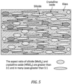
- the aspect ratio of the silicide (e.g., MoSi 2 ) and crystalline oxide (e.g., HfSiO 4 ) are typically greater than 3:1. That is, the 3 of the 3:1 aspect ratio describes a major axis of the particle splat generally along the coating substrate interface and the 1 of the 3:1 aspect ratio describes a minor axis that is transverse thereto.
- the aspect ratio of the silicide (e.g., MoSi 2 ) and crystalline oxide (e.g., HfSiO 4 ) may be greater than 5:1 but less than about 50:1. This would correspond to the case where the HfSiO4 particles mostly do not melt during deposition, but the MoSi2 particles do melt.
- an environmental protective top coat layer 130 may then optionally be applied (step 30) upon the oxidation resistant bond coat layer 120 to impart additional protection from oxidation or steam.
- the environmental protective top coat layer 130 may be an environmental barrier coating of at least one of, yttrium silicates and rare earth silicates, hafnium silicate, and RE oxides and hafnium oxide for protection against combustion gas in turbine environment.
- the environmental protective top coat layer 130 may contain a refractory material including oxides, rare earth oxides, metal silicates, rare earth silicates or mixtures thereof.
- Suitable coating techniques to apply the environmental protective top coat layer 130 may include, but are not limited to, thermal spraying, chemical vapor deposition, physical vapor deposition, electrophoretic deposition, electrostatic deposition, preceramic polymer pyrolysis, sol-gel, slurry coating, dipping, air-brushing, sputtering, slurry painting, high velocity oxygen fuel processes, low pressure plasma spray processes, and the like.
- the article 104 may be heat treated (step 32).
- the article 104 may be heat treated in an inert atmosphere, such as argon, under vacuum to form the healing silica matrix and metallic, intermetallic, or metal silicide network.
- the silica based material, oxygen scavenger, and optional alkaline earth material form a healing silica based matrix with the oxygen scavenger network interwound throughout the layer of the healing silica matrix.
- the heat treatment may be performed by any of a number of conventional techniques.
- the heat treatment temperature depends on the constituents, and may range from 932F (500C) to 3,000F (1650C).
- the article 104 may be heat treated in a temperature range of 2012F (1100C) to 2552F (1400C) for a period of time sufficient to form the healing silica matrix and metallic, intermetallic, or metal silicide network. More specifically, the article 104 may be heat treated for 8 hours at 2102F (1150C) under vacuum.
- the silicide based material network can be formed by sintering a uniform composition of silicide based materials or by reacting single or multiple metal constituents with silicon and metal borides under an inert atmosphere at a temperature below the melting temperature of silicon (e.g., about 2550F; 1400C).
- a temperature below the melting temperature of silicon e.g., about 2550F; 1400C.
- chemical reactions may occur between the metals, intermetallic, or metal silicide/borides (oxygen scavenger) and the components in the silica matrix materials at temperatures higher than 1150C in inert atmosphere to form gaseous products such as SiO(g).
- the heat treatment temperatures therefore, should be below the reaction temperature 2190F (1200C) to form healing silica based matrix only and avoid bond coat decomposition.
- a second heat treatment in air at temperatures higher than 2732F (1500C) may be required to form the silicide based material network.
- the second heat treatment is in air, to form the silicide based material network when the first heat treatment in inert atmospheric is below 2732F (1500C).
- Not all the compositions need a second heat treatment in air, for example, when the first heat treatment were conducted at temperatures below 1350C and the metal silicide would not otherwise form continuous network.
- the silicide based materials sinter and form an interconnected network within the healing silica matrix formed during the prior heat treatment in air at temperature in the range of 2372F - 3002 F (1300C-1650C).
- This heat treatment in air avoids the formation of gaseous reaction products such as SiO (g) between silicide and silica based matrix.
- the healing silica matrix formed during the prior heat treatment surrounds and coats the oxygen scavenger surface and protects it from oxidation during heat treatment in air.
- the silicide based material network is formed through sintering of metal, intermetallic, or metal silicide particles.
- the silica formed on the surface is dense and can protect the silicide based material from being quickly consumed thereby increasing the longevity of the oxidation resistant bond coat layer.
- metal borides may be incorporated into the silicide based material network.
- the metal borides may also reside in the silica based matrix, outside of the network.
- the silicide based material network can be produced by silicide forming precursors, along with silica containing matrix constituents. The metals react with the silicon and boron/boride during heat treatment to form the metal, intermetallic, or metal silicide network that is embedded in the healing silica matrix.
- the silica based matrix operates as a sealant to slow oxygen diffusion and protect the metal silicide from rapidly oxidizing.
- Some silicide based materials such as molybdenum disilicide, can oxidize relatively quickly at 930 - 1650 F (500-900 C) due to insufficient formation of a protective scale such as silica at this temperature range.
- the silica based matrix provides protection in this temperature range and contains the glass phases (e.g., borosilicate glass, alkaline earth aluminum silicate glass, etc.) to provide the healing during engine operation.
- Various top coat layers with varying compositions can be applied to achieve a desired environmental protection and thermal expansion match among the substrate, the oxidation protection coating, and the top coat.
- the glass phases in silica based materials exhibit a viscosity of 10 2 poise (10 Pa s) to 10 7 poise (10 MPa s) in a temperature range of 1292F (700C) to 3272F (1800C), to form a viscous glass material, that when heat treated, is suitable to heal cracks in the oxidation resistant bond coat.
- the composite bond coat containing metallic or intermetallic network and silica based matrix has a rigid structure to resist creep at high temperatures.
- the oxidation resistant bond coat layer provides oxidation resistance by providing a barrier to oxygen flow to the article's surface, reacting with oxygen when small amount of oxygen diffused into the bond coat and healing of the bond coat cracks.
- the oxidation resistant bond coat layer is exposed to oxidative operating conditions overtime, the oxidation resistant bond coat degrades and exposes the oxygen scavenger additive.
- the oxygen scavengers oxidize to form non-gaseous oxidation products such as metal oxides and SiO 2 , Al 2 O 3 , B 2 O 3 , etc.
- the Silicon dioxide (SiO 2 ) is dense and protects the oxidation scavengers from further oxidation.
- Boron trioxide (B 2 O 3 ) forms borosilicate glass phases and flows at elevated temperature to seal cracks and regenerates the glass phases in the silica based matrix, therefore prolong the life of the oxidation protective bond.
- the composite bond coat containing the metallic or intermetallic network and healing silica based matrix accommodate mismatches of the coefficient of thermal expansion of the articles and metallic or intermetallic materials in the bond coat layer. As a result, the oxidation resistant bond coat layer resists spallation and cracking.
- the article 104 may represent any component, part of a component, etc., that requires protection from oxidation across a temperature range up to 3,000 F (1,650 C).
- Such articles may include, but are not limited to, turbine engine components such as vanes, blades, nozzles, flaps, seals, shrouds, and the like, hypersonic engine components such as leading edges and heat exchangers, and hypersonic components such as hypersonic airfoil surfaces, and the like.
- the article 104 may be manufactured of any suitable material, such as, for example, silicon-containing articles to include but not be limited to, silicon-containing ceramics, silicon-containing metal alloys, etc.
- suitable silicon-containing ceramics include, but are not limited to, silicon nitride, silicon carbide, silicon carbonitride, silicon oxycarbides, silicon carbide composites, silicon nitride composites, silicon oxynitrides, silicon aluminum oxynitrides, silicon nitride ceramic matrix composites, etc.
- Suitable silicon-containing metal alloys include, but are not limited to, molybdenum silicon alloys, niobium silicon alloys, iron silicon alloys, cobalt silicon alloys, nickel silicon alloys, tantalum silicon alloys, refractory metal silicides, etc.
- the article 104 may alternatively be manufactured of ceramic matrix composites, for example, ceramic fibers embedded in a ceramic matrix, thus forming a ceramic fiber reinforced ceramic.
- the matrix and fibers can comprise any ceramic material, whereby carbon and carbon fibers can also be considered a ceramic material.
- a metallic, intermetallic, or metal silicide network 142 and a healing silica matrix 144 are combined together in the resultant environmental barrier coating 120 to provide maximum oxidation protection for the article 104.
- the metallic, intermetallic, or metal silicide network 142 is embedded in the healing silica matrix 144 such that the environmental barrier coating 120 readily binds to the article 104. This provides stability against blow off and creep under high surface gas velocities and the forces generated in a gas turbine engine application.
- the structural network of the silicide is adhered so that the glass in the coating does not blow off when molten.
- the network contains the glass.
- the oxygen scavenger reacts with oxygen diffused into the oxygen resistant coating 120 and removes the oxygen.
- the oxygen scavengers dispersed throughout the environmental barrier coating 120 circumvent potential problems associated with coefficient of thermal expansion mismatches which may result in spallation and cracking. That is, the oxygen scavenger stops oxygen from reaching the article 104.
- the environmental protective top coat layer 130 may become exposed to oxidative operating conditions such that the environmental protective top coat layer 130 may degrade as micro-cracks 150 are formed.
- the oxygen scavengers of the healing silica matrix 144 form non-gaseous oxidation products such as metal oxides and SiO 2 , Al 2 O 3 , B 2 O 3 , metal silicates, etc.
- the oxygen scavengers of the healing silica matrix 144 within the oxygen resistant coating 120 migrate at elevated temperature, to repair the micro-cracks 150.
- Example components in hypersonic and/or gas turbine applications require environmental protection in different conditions that may or may not include water vapor.
- scramj et engine leading edges require dry oxidation resistance up to and greater than 3,000 F (1,650 C) while cooled CMC flow path components, e.g., heat exchangers, require protection under relatively high water vapor conditions.
- the environmental protective top coat layer 130 provides environmental protection against such water vapor attack at high temperatures. Multiple layers may provide additional protection against steam and may be used to modify the heat flux through the oxidation resistant bond coat layers, e.g., modify emissivity, reflectance, etc.
- the oxidation resistant bond coat layer 120 protects materials from oxidation in a range of temperatures from room temperature to up to at least 3000F (1650C) and greater.
- the oxidation resistant bond coat layer 120 provides a metal silicide network in a healing matrix.
- the interstices between the metal silicide network is filled with and coated by silica based healing matrix containing glass phases to protect the substrate and provide the healing function.
- the metal silicide network and the glass containing silica based healing matrix are interwound.
- the glass phases in the silica healing matrix melt at high temperature to seal cracks formed and heal the bond coat. This provides a stable coating at high temperature that prolongs service life.
- the healing matrix may be somewhat rigid to maintain a stable coating structure.
- the architecture of the oxidation resistant bond coat layer 120 is also applicable to other materials requiring oxidation protection over a broad temperature range to ensure optimal performance.
- the coefficient of thermal expansion (CTE) of the oxidation resistant bond coat layer 120 can be adjusted by varying the volume fraction and type of the metal silicide or other metallic or intermetallic network and healing silica or other glassy matrix to minimize coefficient of thermal expansion mismatch between the layers of the oxidation resistant bond coat layer.
- the oxidation resistant bond coat layer 120 provides oxidation resistance by providing a barrier to oxygen flow to the article surface, reacting with oxygen when small amount of oxygen diffused into the bond coat.
- the oxidation resistant bond coat layer 120 degrades and exposes the oxygen scavenger additive.
- the oxygen scavengers additive oxidize to form non-gaseous oxidation products such as metal oxides and SiO 2 , Al 2 O 3 , B 2 O 3 , etc.
- the SiO 2 is dense and protects the oxidation scavengers from further oxidation.
- B 2 O 3 forms borosilicate glass phases and flows at elevated temperature to seal cracks and regenerates the glass phases in the silica based matrix to prolong the life of the environmental barrier coating 100.
- the multi-component coating is operable to protect advanced structural materials at elevated temperatures associated with efficient turbine operation.
- Thermal spray methods are a cost-effective and robust method of fabricating coatings on complex shaped components.
Landscapes
- Chemical & Material Sciences (AREA)
- Engineering & Computer Science (AREA)
- Ceramic Engineering (AREA)
- Materials Engineering (AREA)
- Organic Chemistry (AREA)
- Structural Engineering (AREA)
- Physics & Mathematics (AREA)
- Plasma & Fusion (AREA)
- Mechanical Engineering (AREA)
- Chemical Kinetics & Catalysis (AREA)
- Metallurgy (AREA)
- Inorganic Chemistry (AREA)
- General Engineering & Computer Science (AREA)
- Turbine Rotor Nozzle Sealing (AREA)
- Coating By Spraying Or Casting (AREA)
Abstract
Description
- The present disclosure relates to coatings and, more particularly, to an environmental barrier coating that utilizes a multi-component layer that imparts oxidation protection.
- Gas turbine engines and hypersonic engines that are currently being pursued for enhanced performance and improved operational efficiencies will require stable lightweight materials with robust mechanical properties across a wide temperature spectrum. Coatings can increase the durability of hot-section components. The structural materials, such as advanced alloys and composites, in these components can be susceptible to degradation from the combustion gas and the coatings can reduce the severity of this harsh environment. The coating must maintain chemical and mechanical compatibility with the article while imparting both environmental and thermal protection.
- From a first aspect, there is provided a coated article that includes an article having a surface; and an oxidation resistant bond coat layer deposited on the surface, the oxidation resistant bond coat layer comprising a metal silicide phase, a crystalline ceramic phase and an amorphous ceramic phase, wherein the metal silicide phase has an aspect ratio greater than 1:1 but less than 50:1.
- In embodiments of the above, the metal silicide phase and the crystalline ceramic phase each have an aspect ratio greater than 3:1.
- In embodiments of any of the above, the metal silicide phase and the crystalline ceramic phase each have an aspect ratio greater than 5:1.
- In embodiments of any of the above, a volume fraction of the metal silicide phase ranges between 20-80 vol.%, a volume fraction of the crystalline ceramic phase is 25-75 vol.%, and a volume fraction of the amorphous ceramic phase ranges between 1-30 vol.%.
- In embodiments of any of the above, a volume fraction of the metal silicide phase is 60 vol.% MoSi2, a volume fraction of the crystalline ceramic phase is 25 vol.% HfSiO4, and a volume fraction of the amorphous ceramic phase is 15 vol.% boro-silicate glass where the glass has the composition (Si0.75B0.15Al0.05Na0.05)O2 with porosity less than 10%.
- In embodiments of any of the above, a volume fraction of the metal silicide phase is 60 vol.% MoSi2, a volume fraction of the crystalline ceramic phase is 25 vol.% HfSiO4, and 5% HfB2; and a volume fraction of the amorphous ceramic phase is 10 vol.% boro-silicate glass where the glass has the composition (Si0.75B0.15Al0.05Na0.05)O2 with porosity less than 10%.
- In embodiments of any of the above, an environmental protective top coat layer is disposed upon the oxidation resistant bond coat layer, whereby the oxidation resistant bond coat layer is operable to repair a crack in the environmental protective top coat layer during operation of the coated article.
- In embodiments of any of the above, the metal silicide phase has an aspect ratio greater than 3:1.
- In embodiments of any of the above, the metal silicide phase has an aspect ratio greater than 5:1.
- There is also provided a process for applying a coating to an article that includes mixing a silicide powder, a ceramic powder, and a glass powder to form a mixed powder feedstock; injecting the mixed powder feedstock into a plasma torch that is directed at a surface of the article to at least partially melt the silicide powder, the ceramic powder, and the glass powder; and controlling a particle diameter of the silicide powder, the ceramic powder, and the glass powder to control the extent of the melting to form an oxidation resistant bond coat layer.
- In embodiments of the above, a volume fraction of the metal silicide phase ranges between 20-80 vol.%, a volume fraction of the crystalline ceramic phase is 25-75 vol.%, and a volume fraction of the amorphous ceramic phase ranges between 1-30 vol.%.
- In embodiments of any of the above, a volume fraction of the metal silicide phase is 60 vol.% MoSi2, a volume fraction of the crystalline ceramic phase is 25 vol.% HfSiO4, and a volume fraction of the amorphous ceramic phase is 15 vol.% boro-silicate glass where the glass has the composition (Si0.75B0.15Al0.05Na0.05)O2 with porosity less than 10%.
- In embodiments of any of the above, a volume fraction of the metal silicide phase is 60 vol.% MoSi2, a volume fraction of the crystalline ceramic phase is 25 vol.% HfSiO4, and 5% HfB2; and a volume fraction of the amorphous ceramic phase is 10 vol.% boro-silicate glass where the glass has the composition (Si0.75B0.15Al0.05Na0.05)O2 with porosity less than 10%.
- In embodiments of any of the above, the particle diameter of the ceramic powder is greater than the particle diameter of the silicide powder and the glass powder.
- In embodiments of any of the above, the ceramic powder is melted less than that of the silicide powder and the glass powder.
- In embodiments of any of the above, the process includes depositing an environmental protective top coat layer upon the oxidation resistant bond coat layer, whereby the oxidation resistant bond coat layer is operable to repair a crack in the environmental protective top coat layer during operation of the coated article.
- There is also provided a process for applying a coating to an article that includes injecting a silicide powder into a plasma torch that is directed at a surface of the article to at least partially melt the silicide powder; injecting a ceramic powder into the plasma torch that is directed at the surface of the article to at least partially melt the ceramic powder; injecting a glass powder into the plasma torch that is directed at the surface of the article to at least partially melt the glass powder; and controlling a particle diameter of the silicide powder, the ceramic powder, and the glass powder to control the extent of the melting to form an oxidation resistant bond coat layer.
- In embodiments of the above, the process includes injecting the silicide powder, the ceramic powder, and the glass powder occurs simultaneously.
- In embodiments of any of the above, the silicide powder is injected upstream of the ceramic powder.
- In embodiments of any of the above, the ceramic powder is injected upstream of the glass powder.
- The foregoing features and elements may be combined in various combinations without exclusivity, unless expressly indicated otherwise. These features and elements as well as the operation thereof will become more apparent in light of the following description and the accompanying drawings. It should be appreciated; however, the following description and drawings are intended to be exemplary in nature and non-limiting.
- Various features will become apparent to those skilled in the art from the following detailed description of the disclosed non-limiting embodiment. The drawings that accompany the detailed description can be briefly described as follows:
-
FIG. 1 is a block diagram of a process for applying an environmental barrier coating to an article. -
FIG. 2 is a schematic view of an article coated with an environmental barrier coating. -
FIG. 3 is a schematic view of the process according to one disclosed non-limiting embodiment. -
FIG. 4 is a schematic view of the process according to one disclosed non-limiting embodiment. -
FIG. 5 is a schematic view of an aspect ratio of the constituents utilized in the process. - With reference to
FIG. 1 , aprocess 20 for applying an environmental barrier coating 100 (FIG. 2 ) tosurface 102 of anarticle 104 is illustrated in a schematic flowchart form. Theenvironmental barrier coating 100 includes a metal silicide, a crystalline ceramic, and an amorphous ceramic constituent. The volume fraction of each constituent is chosen to optimize a series of properties such as thermal expansion, stiffness, oxidation resistance and protection, and durability. The coating constituents in the form of powders are selected in terms of, for example, particle size and chemistry, along with the deposition conditions to produce the desired coating structure. Thearticle 104 may be manufactured of a ceramic matrix composite (CMC) for use in a hot section of a turbine engine. - In one embodiment, a silicide powder (e.g., molybdenum disilicide, silicon dioxide under ceramic powder or glass), a ceramic powder (e.g., hafnium silicate, hafnium dioxide, hafnium diboride), and a glass powder (e.g., borosilicate glass) are mixed (step 22) in a dry format to form a mixed
powder feedstock 200. Suitable mixing processes may include, but are not limited to, mechanical mixing techniques, manual mixing techniques, ultrasonics, cavitation, agitation, and combinations of these techniques, and the like. For example, representative mechanical mixing techniques may include grinding, ball mixing, high energy milling, shear mixing, stirring, centrifugal mixing, and combinations thereof. - In one example, the
powder feedstock 200 may be composed of a metal silicide (e.g., MoSi2, WSi2, VSi2); a crystalline oxide (e.g., HfSiO4); and a borosilicate glass (e.g., (Si0.75B0.15Al0.05Na0.05)O2. The volume fraction of the silicide phase may range between 20-80 vol.%; the volume fraction of crystalline phase may range between 25-75 vol.%; and 1-30 vol.% amorphous. One disclosed embodiment includes: 60 vol.% Molybdenum disilicide (MoSi2), 25 vol.% Hafnium silicate (HfSiO4), and 15 vol.% boro-silicate glass where the glass has the composition (Si0.75B0.15Al0.05Na0.05)O2 with a porosity less than 10%. Another disclosed embodiment includes: 60 vol.% Molybdenum disilicide (MoSi2), 25 vol.% hafnium silicate (HfSiO4), 5% hafnium diboride (HfB2) and 10 vol.% boro-silicate glass where the glass has the composition (Si0.75B0.15Al0.05Na0.05)O2 with a porosity less than 10%. - The mixed
powder feedstock 200 is injected (step 24;FIG 3 ) into aplasma torch 300 that is directed at thesurface 102 of thearticle 104. In an alternative embodiment, the silicide powder, the ceramic powder, and the glass powder are individually injected into theplasma torch 300 adjacent to atip 302 thereof (FIG. 4 ). For example, the silicide powder may be injected through afirst injector 304 that is closest to thetip 302, next the ceramic powder is injected through asecond injector 306 downstream of thefirst injector 304, and finally the glass powder is injected through athird injector 306 downstream of the second injector 306 (FIG. 4 ). - To obtain a desired coating microstructure and properties, a majority of the feedstock particles are melted (step 26) during flight to the
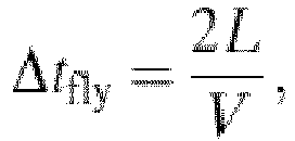
surface 102 of thearticle 104. The power of theplasma torch 300 and the size of the ceramic particles are coordinated such that the desired energy is imparted to the particles to provide a desired melting and thus a desired aspect ratio. A particle melt index (MI) of the particles may be described as follows:
-
- kp = particle thermal conductivity
- h = heat transfer coefficient
- ΔHSL= heat to melt particle
- Tg = gas temperature
- Tm = particle melting temperature
- Δtfly = resonance time
-
- Tf= flame temperature
- h =heat transfer coefficient
- V =flame velocity
- L =distance between torch and substrate
- The particle diameter of each feedstock constituent is an extrinsic property that can be controlled to influence the extent of melting and thereby the aspect ratio when applied. That is, more refractory particles may be smaller and less refractory particles may be larger.
- The melted feedstock propelled by the
plasma torch 300 impact and solidify on thesurface 102 of thearticle 104 to form an oxidation resistant bond coat layer 120 (step 28;FIG.2 ) with particles of a desired aspect ratio. This may be repeated so as to apply more than one layer. - Alternatively, a majority of the silicide and glass particles are melted by the
plasma torch 300 during flight but the ceramic (e.g., HfSiO4) particles melt to only a limited extent less than that of the silicide and glass particles. Once melted, the silicate compounds can solidify into an amorphous state and then crystallize during operation which in some instances may be undesirable such larger ceramic particles may be injected into theplasma torch 300 so that relatively limited melting thereof occurs. The molten silicide and glass particles will thereby produce a dense coating. - With reference to
FIG. 5 , the aspect ratio of the silicide (e.g., MoSi2) and crystalline oxide (e.g., HfSiO4) are typically greater than 3:1. That is, the 3 of the 3:1 aspect ratio describes a major axis of the particle splat generally along the coating substrate interface and the 1 of the 3:1 aspect ratio describes a minor axis that is transverse thereto. Alternatively, the aspect ratio of the silicide (e.g., MoSi2) and crystalline oxide (e.g., HfSiO4) may be greater than 5:1 but less than about 50:1. This would correspond to the case where the HfSiO4 particles mostly do not melt during deposition, but the MoSi2 particles do melt. An alternative embodiment would be where the HfSiO4 melt, so as to have a relatively high aspect ratio, and the MoSi2 is mostly un-melted and has a lower aspect ratio. This could be advantageous from an oxidation point of view, such that the aspect ratio of MoSi2 is closer to 1:1. The molten or semi-molten particles splat when they strike the substrate creating the aspect ratio before solidifying. They thereby have an orientation with the major axis generally along the coating substrate interface. - In some embodiments, an environmental protective
top coat layer 130 may then optionally be applied (step 30) upon the oxidation resistantbond coat layer 120 to impart additional protection from oxidation or steam. The environmental protectivetop coat layer 130 may be an environmental barrier coating of at least one of, yttrium silicates and rare earth silicates, hafnium silicate, and RE oxides and hafnium oxide for protection against combustion gas in turbine environment. The environmental protectivetop coat layer 130 may contain a refractory material including oxides, rare earth oxides, metal silicates, rare earth silicates or mixtures thereof. Suitable refractory oxide materials may include, but are not limited to, at least one of the following oxides: TaxOy (where x=1-3 and y=1-5), NbxOy (where x=1-3 and y=1-5), MgO, CaO, SrO, BaO, SiO2, HfO2, TiO2, ZrO2, Al2O3, Y2O3, La2O3, rare earth oxides, HfSiO4, Y2Si2O7, Y2Si05, rare-earth silicates mixtures thereof, and the like. Suitable coating techniques to apply the environmental protectivetop coat layer 130 may include, but are not limited to, thermal spraying, chemical vapor deposition, physical vapor deposition, electrophoretic deposition, electrostatic deposition, preceramic polymer pyrolysis, sol-gel, slurry coating, dipping, air-brushing, sputtering, slurry painting, high velocity oxygen fuel processes, low pressure plasma spray processes, and the like. - Next, the
article 104 may be heat treated (step 32). In one embodiment, thearticle 104 may be heat treated in an inert atmosphere, such as argon, under vacuum to form the healing silica matrix and metallic, intermetallic, or metal silicide network. The silica based material, oxygen scavenger, and optional alkaline earth material form a healing silica based matrix with the oxygen scavenger network interwound throughout the layer of the healing silica matrix. The heat treatment may be performed by any of a number of conventional techniques. The heat treatment temperature depends on the constituents, and may range from 932F (500C) to 3,000F (1650C). In one example, thearticle 104 may be heat treated in a temperature range of 2012F (1100C) to 2552F (1400C) for a period of time sufficient to form the healing silica matrix and metallic, intermetallic, or metal silicide network. More specifically, thearticle 104 may be heat treated for 8 hours at 2102F (1150C) under vacuum. - The silicide based material network can be formed by sintering a uniform composition of silicide based materials or by reacting single or multiple metal constituents with silicon and metal borides under an inert atmosphere at a temperature below the melting temperature of silicon (e.g., about 2550F; 1400C). In some silicide based materials, chemical reactions may occur between the metals, intermetallic, or metal silicide/borides (oxygen scavenger) and the components in the silica matrix materials at temperatures higher than 1150C in inert atmosphere to form gaseous products such as SiO(g). The heat treatment temperatures, therefore, should be below the reaction temperature 2190F (1200C) to form healing silica based matrix only and avoid bond coat decomposition.
- A second heat treatment in air at temperatures higher than 2732F (1500C) may be required to form the silicide based material network. In some embodiments, the second heat treatment is in air, to form the silicide based material network when the first heat treatment in inert atmospheric is below 2732F (1500C). Not all the compositions need a second heat treatment in air, for example, when the first heat treatment were conducted at temperatures below 1350C and the metal silicide would not otherwise form continuous network. The silicide based materials sinter and form an interconnected network within the healing silica matrix formed during the prior heat treatment in air at temperature in the range of 2372F - 3002 F (1300C-1650C). This heat treatment in air avoids the formation of gaseous reaction products such as SiO (g) between silicide and silica based matrix. The healing silica matrix formed during the prior heat treatment surrounds and coats the oxygen scavenger surface and protects it from oxidation during heat treatment in air.
- The silicide based material network is formed through sintering of metal, intermetallic, or metal silicide particles. The silica formed on the surface is dense and can protect the silicide based material from being quickly consumed thereby increasing the longevity of the oxidation resistant bond coat layer. In one example, metal borides may be incorporated into the silicide based material network. The metal borides may also reside in the silica based matrix, outside of the network. Alternatively, the silicide based material network can be produced by silicide forming precursors, along with silica containing matrix constituents. The metals react with the silicon and boron/boride during heat treatment to form the metal, intermetallic, or metal silicide network that is embedded in the healing silica matrix.
- The silica based matrix operates as a sealant to slow oxygen diffusion and protect the metal silicide from rapidly oxidizing. Some silicide based materials, such as molybdenum disilicide, can oxidize relatively quickly at 930 - 1650 F (500-900 C) due to insufficient formation of a protective scale such as silica at this temperature range. The silica based matrix provides protection in this temperature range and contains the glass phases (e.g., borosilicate glass, alkaline earth aluminum silicate glass, etc.) to provide the healing during engine operation. Various top coat layers with varying compositions can be applied to achieve a desired environmental protection and thermal expansion match among the substrate, the oxidation protection coating, and the top coat.
- The glass phases in silica based materials exhibit a viscosity of 102 poise (10 Pa s) to 107 poise (10 MPa s) in a temperature range of 1292F (700C) to 3272F (1800C), to form a viscous glass material, that when heat treated, is suitable to heal cracks in the oxidation resistant bond coat. The composite bond coat containing metallic or intermetallic network and silica based matrix has a rigid structure to resist creep at high temperatures. The oxidation resistant bond coat layer provides oxidation resistance by providing a barrier to oxygen flow to the article's surface, reacting with oxygen when small amount of oxygen diffused into the bond coat and healing of the bond coat cracks. In addition, as the oxidation resistant bond coat layer is exposed to oxidative operating conditions overtime, the oxidation resistant bond coat degrades and exposes the oxygen scavenger additive. The oxygen scavengers oxidize to form non-gaseous oxidation products such as metal oxides and SiO2, Al2O3, B2O3, etc.
- The Silicon dioxide (SiO2) is dense and protects the oxidation scavengers from further oxidation. Boron trioxide (B2O3) forms borosilicate glass phases and flows at elevated temperature to seal cracks and regenerates the glass phases in the silica based matrix, therefore prolong the life of the oxidation protective bond. The composite bond coat containing the metallic or intermetallic network and healing silica based matrix accommodate mismatches of the coefficient of thermal expansion of the articles and metallic or intermetallic materials in the bond coat layer. As a result, the oxidation resistant bond coat layer resists spallation and cracking.
- With reference again to
FIG. 2 , thearticle 104 may represent any component, part of a component, etc., that requires protection from oxidation across a temperature range up to 3,000 F (1,650 C). Such articles may include, but are not limited to, turbine engine components such as vanes, blades, nozzles, flaps, seals, shrouds, and the like, hypersonic engine components such as leading edges and heat exchangers, and hypersonic components such as hypersonic airfoil surfaces, and the like. - The
article 104 may be manufactured of any suitable material, such as, for example, silicon-containing articles to include but not be limited to, silicon-containing ceramics, silicon-containing metal alloys, etc. Suitable silicon-containing ceramics include, but are not limited to, silicon nitride, silicon carbide, silicon carbonitride, silicon oxycarbides, silicon carbide composites, silicon nitride composites, silicon oxynitrides, silicon aluminum oxynitrides, silicon nitride ceramic matrix composites, etc. Suitable silicon-containing metal alloys include, but are not limited to, molybdenum silicon alloys, niobium silicon alloys, iron silicon alloys, cobalt silicon alloys, nickel silicon alloys, tantalum silicon alloys, refractory metal silicides, etc. Thearticle 104 may alternatively be manufactured of ceramic matrix composites, for example, ceramic fibers embedded in a ceramic matrix, thus forming a ceramic fiber reinforced ceramic. The matrix and fibers can comprise any ceramic material, whereby carbon and carbon fibers can also be considered a ceramic material. - A metallic, intermetallic, or
metal silicide network 142 and ahealing silica matrix 144 are combined together in the resultantenvironmental barrier coating 120 to provide maximum oxidation protection for thearticle 104. The metallic, intermetallic, ormetal silicide network 142 is embedded in thehealing silica matrix 144 such that theenvironmental barrier coating 120 readily binds to thearticle 104. This provides stability against blow off and creep under high surface gas velocities and the forces generated in a gas turbine engine application. The structural network of the silicide is adhered so that the glass in the coating does not blow off when molten. The network contains the glass. - The oxygen scavenger reacts with oxygen diffused into the oxygen
resistant coating 120 and removes the oxygen. The oxygen scavengers dispersed throughout theenvironmental barrier coating 120 circumvent potential problems associated with coefficient of thermal expansion mismatches which may result in spallation and cracking. That is, the oxygen scavenger stops oxygen from reaching thearticle 104. - During engine operation, the environmental protective
top coat layer 130 may become exposed to oxidative operating conditions such that the environmental protectivetop coat layer 130 may degrade asmicro-cracks 150 are formed. The oxygen scavengers of thehealing silica matrix 144 form non-gaseous oxidation products such as metal oxides and SiO2, Al2O3, B2O3, metal silicates, etc. The oxygen scavengers of thehealing silica matrix 144 within the oxygenresistant coating 120 migrate at elevated temperature, to repair themicro-cracks 150. - Example components in hypersonic and/or gas turbine applications require environmental protection in different conditions that may or may not include water vapor. For example, scramj et engine leading edges require dry oxidation resistance up to and greater than 3,000 F (1,650 C) while cooled CMC flow path components, e.g., heat exchangers, require protection under relatively high water vapor conditions. The environmental protective
top coat layer 130 provides environmental protection against such water vapor attack at high temperatures. Multiple layers may provide additional protection against steam and may be used to modify the heat flux through the oxidation resistant bond coat layers, e.g., modify emissivity, reflectance, etc. - The oxidation resistant
bond coat layer 120 protects materials from oxidation in a range of temperatures from room temperature to up to at least 3000F (1650C) and greater. The oxidation resistantbond coat layer 120 provides a metal silicide network in a healing matrix. The interstices between the metal silicide network is filled with and coated by silica based healing matrix containing glass phases to protect the substrate and provide the healing function. In embodiments, there is minimal porosity in the oxidation resistantbond coat layer 120. - The metal silicide network and the glass containing silica based healing matrix, are interwound. The glass phases in the silica healing matrix melt at high temperature to seal cracks formed and heal the bond coat. This provides a stable coating at high temperature that prolongs service life. The healing matrix may be somewhat rigid to maintain a stable coating structure. Although especially applicable to low thermal expansion composite substrates such as C/SiC, SiC/SiC or SiC/SiNC and monolithic Si3N4, the architecture of the oxidation resistant
bond coat layer 120 is also applicable to other materials requiring oxidation protection over a broad temperature range to ensure optimal performance. The coefficient of thermal expansion (CTE) of the oxidation resistantbond coat layer 120 can be adjusted by varying the volume fraction and type of the metal silicide or other metallic or intermetallic network and healing silica or other glassy matrix to minimize coefficient of thermal expansion mismatch between the layers of the oxidation resistant bond coat layer. - The oxidation resistant
bond coat layer 120 provides oxidation resistance by providing a barrier to oxygen flow to the article surface, reacting with oxygen when small amount of oxygen diffused into the bond coat. In addition, as the oxidation resistantbond coat layer 120 is exposed to oxidative operating conditions over time, the oxidation resistant bond coat degrades and exposes the oxygen scavenger additive. The oxygen scavengers additive oxidize to form non-gaseous oxidation products such as metal oxides and SiO2, Al2O3, B2O3, etc. The SiO2 is dense and protects the oxidation scavengers from further oxidation. B2O3 forms borosilicate glass phases and flows at elevated temperature to seal cracks and regenerates the glass phases in the silica based matrix to prolong the life of theenvironmental barrier coating 100. - The multi-component coating is operable to protect advanced structural materials at elevated temperatures associated with efficient turbine operation. Thermal spray methods are a cost-effective and robust method of fabricating coatings on complex shaped components.
- Although the different non-limiting embodiments have specific illustrated components, the embodiments of this application are not limited to those particular combinations. It is possible to use some of the components or features from any of the non-limiting embodiments in combination with features or components from any of the other non-limiting embodiments.
- Although particular step sequences are shown, described, and claimed, it should be appreciated that steps may be performed in any order, separated or combined unless otherwise indicated and will still benefit from the present disclosure.
- The foregoing description is exemplary rather than defined by the limitations within. Various non-limiting embodiments are disclosed herein; however, one of ordinary skill in the art would recognize that various modifications and variations in light of the above teachings will fall within the scope of the appended claims. It is therefore to be appreciated that within the scope of the appended claims, the disclosure may be practiced other than as specifically described. For that reason, the appended claims should be studied to determine true scope and content.
Claims (15)
- A coated article (104), comprising:an article (104) having a surface (102); andan oxidation resistant bond coat layer (120) deposited on the surface (102), the oxidation resistant bond coat layer (120) comprising a metal silicide phase (142), a crystalline ceramic phase and an amorphous ceramic phase (144), wherein the metal silicide phase (142) has an aspect ratio greater than 1:1 but less than 50:1.
- The coated article (104) as recited in claim 1, wherein the metal silicide phase (142) and the crystalline ceramic phase each have an aspect ratio greater than 3:1, and optionally greater than 5:1.
- The coated article (104) as recited in claim 1 or 2, further comprising an environmental protective top coat layer (130) disposed upon the oxidation resistant bond coat layer (120), whereby the oxidation resistant bond coat layer (120) is operable to repair a crack (150) in the environmental protective top coat layer (130) during operation of the coated article (104).
- The coated article (104) as recited in any preceding claim, wherein the metal silicide phase (142) has an aspect ratio greater than 3:1, and optionally greater than 5:1.
- A process for applying a coating (100) to an article (104), comprising:mixing a silicide powder, a ceramic powder, and a glass powder to form a mixed powder feedstock (200);injecting the mixed powder feedstock (200) into a plasma torch (300) that is directed at a surface (102) of the article (104) to at least partially melt the silicide powder, the ceramic powder, and the glass powder; andcontrolling a particle diameter of the silicide powder, the ceramic powder, and the glass powder to control the extent of the melting to form an oxidation resistant bond coat layer (120).
- The coated article (104) as recited in any of claims 1 to 4 or the process as recited in claim 5, wherein a volume fraction of the metal silicide phase (142) ranges between 20-80 vol.%, a volume fraction of the crystalline ceramic phase is 25-75 vol.%, and a volume fraction of the amorphous ceramic phase (144) ranges between 1-30 vol.%.
- The coated article (104) as recited in any of claims 1 to 4 or the process as recited in claim 5, wherein a volume fraction of the metal silicide phase (142) is 60 vol.% MoSi2, a volume fraction of the crystalline ceramic phase is 25 vol.% HfSiO4, and a volume fraction of the amorphous ceramic phase (144) is 15 vol.% boro-silicate glass where the glass has the composition (Si0.75B0.15Al0.05Na0.05)O2 with porosity less than 10%.
- The coated article (104) as recited in any of claims 1 to 4 or the process as recited in claim 5, wherein a volume fraction of the metal silicide phase (142) is 60 vol.% MoSi2, a volume fraction of the crystalline ceramic phase is 25 vol.% HfSiO4, and 5% HfB2; and a volume fraction of the amorphous ceramic phase (144) is 10 vol.% boro-silicate glass where the glass has the composition (Si0.75B0.15Al0.05Na0.05)O2 with porosity less than 10%.
- The process as recited in any of claims 5 to 8, wherein the particle diameter of the ceramic powder is greater than the particle diameter of the silicide powder and the glass powder.
- The process as recited in any of claims 5 to 9, wherein the ceramic powder is melted less than that of the silicide powder and the glass powder.
- The process as recited in any of claims 5 to 10, further comprising depositing an environmental protective top coat layer (130) upon the oxidation resistant bond coat layer (120), whereby the oxidation resistant bond coat layer (120) is operable to repair a crack (150) in the environmental protective top coat layer (130) during operation of the coated article (104).
- A process for applying a coating (100) to an article (104), comprising:injecting a silicide powder into a plasma torch (300) that is directed at a surface (102) of the article (104) to at least partially melt the silicide powder;injecting a ceramic powder into the plasma torch (300) that is directed at the surface (102) of the article (104) to at least partially melt the ceramic powder;injecting a glass powder into the plasma torch (300) that is directed at the surface (102) of the article (104) to at least partially melt the glass powder; andcontrolling a particle diameter of the silicide powder, the ceramic powder, and the glass powder to control the extent of the melting to form an oxidation resistant bond coat layer (120).
- The process as recited in claim 12, wherein injecting the silicide powder, the ceramic powder, and the glass powder occurs simultaneously.
- The process as recited in claim 12, wherein the silicide powder is injected upstream of the ceramic powder.
- The process as recited in claim 14, wherein the ceramic powder is injected upstream of the glass powder.
Applications Claiming Priority (1)
| Application Number | Priority Date | Filing Date | Title |
|---|---|---|---|
| US17/395,992 US11661380B2 (en) | 2021-08-06 | 2021-08-06 | Multi-environmental barrier coating, processes for coating articles, and their coated articles |
Publications (1)
| Publication Number | Publication Date |
|---|---|
| EP4129957A1 true EP4129957A1 (en) | 2023-02-08 |
Family
ID=82839399
Family Applications (1)
| Application Number | Title | Priority Date | Filing Date |
|---|---|---|---|
| EP22188845.6A Pending EP4129957A1 (en) | 2021-08-06 | 2022-08-04 | Multi-environmental barrier coating, processes for coating articles, and their coated articles |
Country Status (2)
| Country | Link |
|---|---|
| US (2) | US11661380B2 (en) |
| EP (1) | EP4129957A1 (en) |
Cited By (1)
| Publication number | Priority date | Publication date | Assignee | Title |
|---|---|---|---|---|
| CN116730747A (en) * | 2023-06-09 | 2023-09-12 | 西安电子科技大学 | Glass ceramic antioxidation coating on surface of carbon-based composite material and preparation method thereof |
Families Citing this family (3)
| Publication number | Priority date | Publication date | Assignee | Title |
|---|---|---|---|---|
| GB202207827D0 (en) * | 2022-05-27 | 2022-07-13 | Rolls Royce Plc | Method of forming protective coating and coated article comprising protective coating |
| US20250313957A1 (en) * | 2024-04-05 | 2025-10-09 | Rtx Corporation | Multi-constituent environmental barrier coating |
| US20250361189A1 (en) * | 2024-05-24 | 2025-11-27 | Rtx Corporation | Method and device for plasma spraying of powders |
Citations (3)
| Publication number | Priority date | Publication date | Assignee | Title |
|---|---|---|---|---|
| US20060280953A1 (en) * | 2005-06-13 | 2006-12-14 | Hazel Brian T | Bond coat for silicon-containing substrate for EBC and processes for preparing same |
| US20130157064A1 (en) * | 2011-12-16 | 2013-06-20 | Wisconsin Alumni Research Foundation | Mo-Si-B-BASED COATINGS FOR CERAMIC BASE SUBSTRATES |
| US20170335118A1 (en) * | 2016-05-19 | 2017-11-23 | United Technologies Corporation | Article having coating with glass, oxygen scavenger, and metal |
Family Cites Families (10)
| Publication number | Priority date | Publication date | Assignee | Title |
|---|---|---|---|---|
| US4060424A (en) * | 1976-02-03 | 1977-11-29 | Norton Company | Low temperature setting refractory cements |
| US6287711B1 (en) * | 1998-07-01 | 2001-09-11 | Front Edge Technology, Inc. | Wear-resistant coating and component |
| US6890668B2 (en) * | 2002-08-30 | 2005-05-10 | General Electric Company | Thermal barrier coating material |
| US20090162670A1 (en) * | 2007-12-20 | 2009-06-25 | General Electric Company | Method for applying ceramic coatings to smooth surfaces by air plasma spray techniques, and related articles |
| US9428650B2 (en) | 2012-12-11 | 2016-08-30 | General Electric Company | Environmental barrier coatings and methods therefor |
| US20150118444A1 (en) | 2013-10-31 | 2015-04-30 | General Electric Company | Methods of manufacturing silica-forming articles having engineered surfaces to enhance resistance to creep sliding under high-temperature loading |
| US10179945B2 (en) * | 2013-12-16 | 2019-01-15 | General Electric Company | CMAS resistant thermal barrier coatings |
| DE102016007231A1 (en) * | 2016-06-15 | 2017-12-21 | Forschungszentrum Jülich GmbH | Self-healing thermal barrier coatings and methods of making same |
| WO2017218759A1 (en) * | 2016-06-15 | 2017-12-21 | The Penn State Research Foundation | Thermal barrier coatings |
| US11459650B2 (en) | 2017-10-20 | 2022-10-04 | Raytheon Technologies Corporation | Oxidation resistant bond coat layers, processes for coating articles, and their coated articles |
-
2021
- 2021-08-06 US US17/395,992 patent/US11661380B2/en active Active
-
2022
- 2022-08-04 EP EP22188845.6A patent/EP4129957A1/en active Pending
-
2023
- 2023-04-24 US US18/138,395 patent/US20230278935A1/en not_active Abandoned
Patent Citations (3)
| Publication number | Priority date | Publication date | Assignee | Title |
|---|---|---|---|---|
| US20060280953A1 (en) * | 2005-06-13 | 2006-12-14 | Hazel Brian T | Bond coat for silicon-containing substrate for EBC and processes for preparing same |
| US20130157064A1 (en) * | 2011-12-16 | 2013-06-20 | Wisconsin Alumni Research Foundation | Mo-Si-B-BASED COATINGS FOR CERAMIC BASE SUBSTRATES |
| US20170335118A1 (en) * | 2016-05-19 | 2017-11-23 | United Technologies Corporation | Article having coating with glass, oxygen scavenger, and metal |
Non-Patent Citations (2)
| Title |
|---|
| "A Basic Guide to Particle Characterization", MALVERN INSTRUMENTS WORLDWIDE - WHITE PAPER, 2 May 2012 (2012-05-02), pages 1 - 26, XP055089322, Retrieved from the Internet <URL:http://golik.co.il/Data/ABasicGuidtoParticleCharacterization(2)_1962085150.pdf> * |
| KIRYUKHANTSEV-KORNEEV PH V ET AL: "Mechanical properties and oxidation resistance of Mo-Si-B and Mo-Hf-Si-B coatings obtained by magnetron sputtering in DC and pulsed DC modes", SURFACE AND COATINGS TECHNOLOGY, ELSEVIER, NL, vol. 403, 31 August 2020 (2020-08-31), XP086355362, ISSN: 0257-8972, [retrieved on 20200831], DOI: 10.1016/J.SURFCOAT.2020.126373 * |
Cited By (1)
| Publication number | Priority date | Publication date | Assignee | Title |
|---|---|---|---|---|
| CN116730747A (en) * | 2023-06-09 | 2023-09-12 | 西安电子科技大学 | Glass ceramic antioxidation coating on surface of carbon-based composite material and preparation method thereof |
Also Published As
| Publication number | Publication date |
|---|---|
| US20230044705A1 (en) | 2023-02-09 |
| US20230278935A1 (en) | 2023-09-07 |
| US11661380B2 (en) | 2023-05-30 |
Similar Documents
| Publication | Publication Date | Title |
|---|---|---|
| EP4129957A1 (en) | Multi-environmental barrier coating, processes for coating articles, and their coated articles | |
| US12146224B2 (en) | Oxidation resistant bond coat layers, processes for coating articles, and their coated articles | |
| EP1925694B1 (en) | Processes for producing oxidation resistant coating articles and their coated articles | |
| CN106927866B (en) | Articles with Enhanced Temperature Capability | |
| US6733908B1 (en) | Multilayer article having stabilized zirconia outer layer and chemical barrier layer | |
| EP3252278B1 (en) | High temperature composites with enhanced matrix | |
| CN111183125B (en) | Component protected by an environmental barrier | |
| EP3842563A1 (en) | Silica-rich barrier coatings | |
| EP3243808A1 (en) | High temperature coating for silicon nitride articles | |
| EP3418420B1 (en) | Impurity barrier layer for ceramic matrix composite substrate | |
| CN114195556A (en) | High temperature resistant ceramic matrix composite and environmental barrier coatings | |
| EP2308810A1 (en) | Ceramic matrix composite system and method of manufacture | |
| EP3604257B1 (en) | Article comprising a fiber-reinforced self-healing bond coat | |
| EP3623355A1 (en) | Compositional control of protective layers | |
| EP3031957A1 (en) | Methods of forming an article using electrophoretic deposition, and related articles | |
| CN117125991B (en) | Method for integrally preparing boride superhigh temperature ceramic coating through mixing | |
| EP0993423B1 (en) | Article having a modified mullite coating and method of making the same | |
| JP5129500B2 (en) | Heat resistant material and method for manufacturing and repairing the same | |
| RU2773286C2 (en) | Part protected with surrounding barrier | |
| Meetham et al. | High Temperature composite materials | |
| CN121295074A (en) | A high-temperature resistant and oxidation-resistant barrier coating adhesive layer and its preparation method | |
| CN118407042A (en) | Bond coating having a metalloid-based material matrix |
Legal Events
| Date | Code | Title | Description |
|---|---|---|---|
| PUAI | Public reference made under article 153(3) epc to a published international application that has entered the european phase |
Free format text: ORIGINAL CODE: 0009012 |
|
| STAA | Information on the status of an ep patent application or granted ep patent |
Free format text: STATUS: THE APPLICATION HAS BEEN PUBLISHED |
|
| AK | Designated contracting states |
Kind code of ref document: A1 Designated state(s): AL AT BE BG CH CY CZ DE DK EE ES FI FR GB GR HR HU IE IS IT LI LT LU LV MC MK MT NL NO PL PT RO RS SE SI SK SM TR |
|
| STAA | Information on the status of an ep patent application or granted ep patent |
Free format text: STATUS: REQUEST FOR EXAMINATION WAS MADE |
|
| 17P | Request for examination filed |
Effective date: 20230720 |
|
| RBV | Designated contracting states (corrected) |
Designated state(s): AL AT BE BG CH CY CZ DE DK EE ES FI FR GB GR HR HU IE IS IT LI LT LU LV MC MK MT NL NO PL PT RO RS SE SI SK SM TR |
|
| RAP3 | Party data changed (applicant data changed or rights of an application transferred) |
Owner name: RTX CORPORATION |
|
| STAA | Information on the status of an ep patent application or granted ep patent |
Free format text: STATUS: EXAMINATION IS IN PROGRESS |
|
| 17Q | First examination report despatched |
Effective date: 20250407 |