EP4129880A1 - Airtight device - Google Patents
Airtight device Download PDFInfo
- Publication number
- EP4129880A1 EP4129880A1 EP22169213.0A EP22169213A EP4129880A1 EP 4129880 A1 EP4129880 A1 EP 4129880A1 EP 22169213 A EP22169213 A EP 22169213A EP 4129880 A1 EP4129880 A1 EP 4129880A1
- Authority
- EP
- European Patent Office
- Prior art keywords
- doors
- airtight
- section
- door
- top surface
- Prior art date
- Legal status (The legal status is an assumption and is not a legal conclusion. Google has not performed a legal analysis and makes no representation as to the accuracy of the status listed.)
- Granted
Links
Images




Classifications
-
- B—PERFORMING OPERATIONS; TRANSPORTING
- B65—CONVEYING; PACKING; STORING; HANDLING THIN OR FILAMENTARY MATERIAL
- B65D—CONTAINERS FOR STORAGE OR TRANSPORT OF ARTICLES OR MATERIALS, e.g. BAGS, BARRELS, BOTTLES, BOXES, CANS, CARTONS, CRATES, DRUMS, JARS, TANKS, HOPPERS, FORWARDING CONTAINERS; ACCESSORIES, CLOSURES, OR FITTINGS THEREFOR; PACKAGING ELEMENTS; PACKAGES
- B65D90/00—Component parts, details or accessories for large containers
- B65D90/54—Gates or closures
- B65D90/58—Gates or closures having closure members sliding in the plane of the opening
- B65D90/587—Gates or closures having closure members sliding in the plane of the opening having a linear motion
-
- B—PERFORMING OPERATIONS; TRANSPORTING
- B65—CONVEYING; PACKING; STORING; HANDLING THIN OR FILAMENTARY MATERIAL
- B65D—CONTAINERS FOR STORAGE OR TRANSPORT OF ARTICLES OR MATERIALS, e.g. BAGS, BARRELS, BOTTLES, BOXES, CANS, CARTONS, CRATES, DRUMS, JARS, TANKS, HOPPERS, FORWARDING CONTAINERS; ACCESSORIES, CLOSURES, OR FITTINGS THEREFOR; PACKAGING ELEMENTS; PACKAGES
- B65D45/00—Clamping or other pressure-applying devices for securing or retaining closure members
- B65D45/02—Clamping or other pressure-applying devices for securing or retaining closure members for applying axial pressure to engage closure with sealing surface
-
- B—PERFORMING OPERATIONS; TRANSPORTING
- B65—CONVEYING; PACKING; STORING; HANDLING THIN OR FILAMENTARY MATERIAL
- B65D—CONTAINERS FOR STORAGE OR TRANSPORT OF ARTICLES OR MATERIALS, e.g. BAGS, BARRELS, BOTTLES, BOXES, CANS, CARTONS, CRATES, DRUMS, JARS, TANKS, HOPPERS, FORWARDING CONTAINERS; ACCESSORIES, CLOSURES, OR FITTINGS THEREFOR; PACKAGING ELEMENTS; PACKAGES
- B65D43/00—Lids or covers for rigid or semi-rigid containers
- B65D43/14—Non-removable lids or covers
- B65D43/16—Non-removable lids or covers hinged for upward or downward movement
-
- B—PERFORMING OPERATIONS; TRANSPORTING
- B65—CONVEYING; PACKING; STORING; HANDLING THIN OR FILAMENTARY MATERIAL
- B65D—CONTAINERS FOR STORAGE OR TRANSPORT OF ARTICLES OR MATERIALS, e.g. BAGS, BARRELS, BOTTLES, BOXES, CANS, CARTONS, CRATES, DRUMS, JARS, TANKS, HOPPERS, FORWARDING CONTAINERS; ACCESSORIES, CLOSURES, OR FITTINGS THEREFOR; PACKAGING ELEMENTS; PACKAGES
- B65D81/00—Containers, packaging elements, or packages, for contents presenting particular transport or storage problems, or adapted to be used for non-packaging purposes after removal of contents
- B65D81/18—Containers, packaging elements, or packages, for contents presenting particular transport or storage problems, or adapted to be used for non-packaging purposes after removal of contents providing specific environment for contents, e.g. temperature above or below ambient
-
- B—PERFORMING OPERATIONS; TRANSPORTING
- B65—CONVEYING; PACKING; STORING; HANDLING THIN OR FILAMENTARY MATERIAL
- B65D—CONTAINERS FOR STORAGE OR TRANSPORT OF ARTICLES OR MATERIALS, e.g. BAGS, BARRELS, BOTTLES, BOXES, CANS, CARTONS, CRATES, DRUMS, JARS, TANKS, HOPPERS, FORWARDING CONTAINERS; ACCESSORIES, CLOSURES, OR FITTINGS THEREFOR; PACKAGING ELEMENTS; PACKAGES
- B65D90/00—Component parts, details or accessories for large containers
- B65D90/54—Gates or closures
- B65D90/58—Gates or closures having closure members sliding in the plane of the opening
- B65D90/60—Gates or closures having closure members sliding in the plane of the opening and having one or more openings
-
- E—FIXED CONSTRUCTIONS
- E05—LOCKS; KEYS; WINDOW OR DOOR FITTINGS; SAFES
- E05B—LOCKS; ACCESSORIES THEREFOR; HANDCUFFS
- E05B17/00—Accessories in connection with locks
- E05B17/0025—Devices for forcing the wing firmly against its seat or to initiate the opening of the wing
-
- E—FIXED CONSTRUCTIONS
- E05—LOCKS; KEYS; WINDOW OR DOOR FITTINGS; SAFES
- E05C—BOLTS OR FASTENING DEVICES FOR WINGS, SPECIALLY FOR DOORS OR WINDOWS
- E05C9/00—Arrangements of simultaneously actuated bolts or other securing devices at well-separated positions on the same wing
-
- F—MECHANICAL ENGINEERING; LIGHTING; HEATING; WEAPONS; BLASTING
- F25—REFRIGERATION OR COOLING; COMBINED HEATING AND REFRIGERATION SYSTEMS; HEAT PUMP SYSTEMS; MANUFACTURE OR STORAGE OF ICE; LIQUEFACTION SOLIDIFICATION OF GASES
- F25D—REFRIGERATORS; COLD ROOMS; ICE-BOXES; COOLING OR FREEZING APPARATUS NOT OTHERWISE PROVIDED FOR
- F25D23/00—General constructional features
- F25D23/02—Doors; Covers
- F25D23/028—Details
-
- F—MECHANICAL ENGINEERING; LIGHTING; HEATING; WEAPONS; BLASTING
- F25—REFRIGERATION OR COOLING; COMBINED HEATING AND REFRIGERATION SYSTEMS; HEAT PUMP SYSTEMS; MANUFACTURE OR STORAGE OF ICE; LIQUEFACTION SOLIDIFICATION OF GASES
- F25D—REFRIGERATORS; COLD ROOMS; ICE-BOXES; COOLING OR FREEZING APPARATUS NOT OTHERWISE PROVIDED FOR
- F25D31/00—Other cooling or freezing apparatus
- F25D31/006—Other cooling or freezing apparatus specially adapted for cooling receptacles, e.g. tanks
-
- A—HUMAN NECESSITIES
- A47—FURNITURE; DOMESTIC ARTICLES OR APPLIANCES; COFFEE MILLS; SPICE MILLS; SUCTION CLEANERS IN GENERAL
- A47F—SPECIAL FURNITURE, FITTINGS, OR ACCESSORIES FOR SHOPS, STOREHOUSES, BARS, RESTAURANTS OR THE LIKE; PAYING COUNTERS
- A47F3/00—Show cases or show cabinets
- A47F3/04—Show cases or show cabinets air-conditioned, refrigerated
- A47F3/0404—Cases or cabinets of the closed type
-
- A—HUMAN NECESSITIES
- A47—FURNITURE; DOMESTIC ARTICLES OR APPLIANCES; COFFEE MILLS; SPICE MILLS; SUCTION CLEANERS IN GENERAL
- A47J—KITCHEN EQUIPMENT; COFFEE MILLS; SPICE MILLS; APPARATUS FOR MAKING BEVERAGES
- A47J47/00—Kitchen containers, stands or the like, not provided for in other groups of this subclass; Cutting-boards, e.g. for bread
- A47J47/02—Closed containers for foodstuffs
-
- E—FIXED CONSTRUCTIONS
- E05—LOCKS; KEYS; WINDOW OR DOOR FITTINGS; SAFES
- E05B—LOCKS; ACCESSORIES THEREFOR; HANDCUFFS
- E05B65/00—Locks or fastenings for special use
- E05B65/0042—For refrigerators or cold rooms
Definitions
- the present disclosure relates to an airtight device. More particularly, the present disclosure relates to an airtight device which can preserve objects.
- storage devices such as freezers, reefer containers, and refrigerators, are widely used to store food and medicine.
- an airtight device includes a container and an airtight cover disposed on the container, in which the airtight cover includes a fixing bracket, at least one door, and at least one pressuring handle.
- the fixing bracket has at least one through hole and at least one guiding slot, and the through hole communicates with an interior space of the container, the guiding slot includes a first top surface and a second top surface higher than the first top surface.
- the at least one door is configured to cover the through hole.
- the at least one pressuring handle which is pivoted to the door has a first section, a second section, and a rotation pivot between the first and second sections, in which the first section and the second section are configured to rotate relative to each other.
- the second section is configured to receive a force for driving the first section to move from below the second top surface to below the first top surface such that the rotation pivot pressures the door.
- the fixing bracket includes a guiding rail, and the door has a protruding portion inserted into the guiding rail.
- the guiding rail is above the through hole and has a first portion which has a height gradually increasing relative to the through hole, and the door is configured to move toward a lowest end of the first portion to be located at a closed height, and the door is also configured to move away from the lowest end of the first portion to be located at an open height.
- the guiding rail has a second portion which has a consistent height relative to the through hole and communicates with a higher end of the first portion.
- the door has a bearing which is disposed at the protruding portion.
- the airtight cover has a connection rod
- the at least one pressuring handle includes a plurality of the pressuring handles, the second sections of the pressuring handles are rotatably connected to the connection rod.
- the airtight cover has a fixing lock, and at least a portion of the fixing lock is disposed at a lateral side of the door, in which the fixing lock is configured to vertically move for locking the door on the fixing bracket.
- the at least one door includes two doors, and each of the two doors includes a sliding rail and a sliding block.
- One of the two doors is configured to move above another one of the two doors, and the sliding block of the one of the two doors is slidably connected to the sliding rail of the another one of the two doors.
- an airtight device including a container, an airtight cover, and a fixing bracket.
- the airtight cover is disposed on the container, and the airtight cover includes a fixing bracket, two doors, and a plurality of pressuring handles.
- the fixing bracket has two through holes and a plurality of guiding slots, in which the two through holes communicate with an interior space of the container, and each of the guiding slots includes a first top surface and a second top surface higher than the first top surface.
- the two doors configured to cover the two through holes respectively.
- the plurality of pressuring handles are pivoted to the two door respectively, each of the pressuring handles having a first section, a second section, and a rotation pivot disposed between the first and second sections, in which the first section and the second section are configured to rotate relative to each other, and the second section is configured to receive a force for driving the first section to move from below the second top surface to below the first top surface such that the rotation pivot pressures a corresponding one of the two doors.
- the fixing bracket has a guiding rail, and each of the two doors has a protruding portion inserted into the siding rail.
- the guiding rail is above the two through holes and has two first portions, and each of the two first portions has a height gradually increasing relative to the two through holes.
- the two doors are configured to respectively move toward to be in a closed state, and the two doors are also configured to respectively move away from lowest ends of the two first portions to be in an open state.
- a second portion of the guiding rail has a consistent height relative to the two through holes, and the second portion which communicates with higher ends of the two first portions is located between the two first portions.
- each of the two doors has a bearing which is disposed at the protruding portion.
- the airtight cover includes a connection rod connected to the fixing bracket and disposed between the two through holes, and the connection rod has a T-shaped section which fixes the two doors from above and lateral.
- the airtight cover includes a fixing lock which has at least a portion disposed at a lateral side of the one of the two doors, and the fixing lock is configured to vertically move to fix the one of the two doors to the fixing bracket.
- each of the two doors includes a sliding rail and a sliding block, and one of the two doors is configured to move above another one of the two doors, the sliding block of the one of the two doors is slidably connected to the sliding rail of the another one of the two doors.
- an airtight device which has a container and an airtight cover is provided, and the airtight cover covers the container and prevents air or liquid from moving in or moving out of the container. Therefore, an object such as food and medicine stored in the container can be isolated from outside space, so as to prevent the air from leaking and prevent the food from decaying and being uneatable.
- the pressuring handles are located on the airtight cover, and the users can easily rotate the pressuring handles to make the airtight cover in the airtight state or release the airtight state.
- an airtight device which has a container and an airtight cover is provided, and the airtight cover covers the container and prevents air or liquid from moving in or moving out of the container. Therefore, an object such as food and medicine stored in the container can be isolated from outside space, so as to prevent the air from leaking and prevent the food from decaying and being uneatable.
- the pressuring handles are located on the airtight cover, and the users can easily rotate the pressuring handles to make the airtight cover in the airtight state or release the airtight state.
- the airtight device 10 can include a freezer, a reefer container, or a refrigerator, in which the airtight device 10 includes a container 100 and an airtight cover 200.
- the airtight cover 200 which is tightly disposed at an opening 110 of the container 100 can entirely cover the opening 110 and seal the container 100, so as to prevent air and liquid from moving in or out from the container 100.
- the container 100 is a rectangular cabinet or a square cabinet, and the container 100 can accommodate many types of objects, such as food and medicine.
- the airtight cover 200 can include a fixing bracket 210, two doors 230, and a plurality of pressuring handles 250, in which users can rotate the pressuring handles 250 to apply pressures to the doors 230 such that the airtight cover 200 is in an airtight condition. Next, the users can reversely rotate the pressuring handles 250 to release the pressures applied to the doors 230 and release the airtight condition of the airtight cover 200.
- the related information and detail structure about the airtight cover 200 are introduced in the following paragraphs.
- the airtight cover 200 includes one single door 230, and the users can place the single door 230 against the fixing bracket 210 and use the pressuring handles 250 to apply pressures to the single door 230 such that the airtight cover 200 is in the airtight condition.
- Fig. 2 illustrates an exploded view of the airtight cover 200.
- Fig. 3 illustrates an enlarged view of the fixing bracket 210 according to the dotted square S1 in the Fig. 2 .
- the fixing bracket 210 has two through holes 211 and a plurality of guiding slots 213, and the through holes 211 communicates with an interior space of the container 100. Therefore, the users can take an object from the container 100 and put an object in the container 100 via the through holes 211 of the airtight cover 200. In addition, the users can move the doors 230 to cover the through holes 211 or leave the through holes 211.
- each of the pressuring handles 250 are pivoted to periphery frames the doors 230, and each of the pressuring handles 250 includes a first section 251, a second section 253, and a rotation pivot 255 which is between the first section 251 and the second section 253, in which the first section 251 and the second section 253 are configured to rotate relative to each other.
- each of the guiding slots 213 includes a first top surface 213a and a second top surface 213b adjacent to the first top surface 213a, and the second top surface 213b which is an interior top surface higher than the first top surface 213a which is another interior top surface.
- the first top surface 213a and the second top surface 213b can form a continuous surface which is a flat surface, an inclined surface, or a curved surface, and the first top surface 213a and the second top surface 213b can form an angle smaller than 90 degrees.
- the first section 251 of each pressuring handle 250 can be pushed and inserted into the corresponding guiding slots 213.
- Figs. 5 and 7 illustrates an enlarged view according to the dotted square S3 in the Fig. 5 .
- Fig. 8 illustrates an enlarged view according to the dotted square S4 in Fig. 6 .
- the fixing bracket 210 can be made of metal, alloy, or polymer which has higher rigidity.
- the fixing bracket 210 is made of steel, aluminum metal, aluminum alloy, or plastic.
- the guiding slots 213 of the fixing bracket 210 can be manufactured by a machining process or a laser cutting process, but the present disclosure is not limited in this respect.
- the doors 230 are in shapes corresponding to shapes of the through holes 211 of the fixing bracket 210, and the doors 230 can be rectangular or square.
- the through holes 211 can also be rectangular or square, and the doors 230 are slightly greater than the through holes 211. Therefore, when the doors 230 respectively cover the through holes 211, the doors 230 can respectively entirely block the through holes 211 from a top view.
- each of the doors 230 includes the periphery frame and a transparent sheet surrounded by the periphery frame such that the users can see the interior space of the container 100 through the doors 230.
- the periphery frame can include metal, alloy, or polymer, such as steel, aluminum metal, aluminum alloy, and plastic which has higher rigidity.
- the transparent sheet can include transparent glass or transparent polymer, but the present disclosure is not limited in this respect.
- the fixing bracket 210 further includes two sidewalls 214 and two guiding rails 215, and the two sidewalls 214 which are respectively located at two corresponding sides of the through holes 211 extend on a top surface of the fixing bracket 210.
- the guiding slots 213 and the two guiding rails 215 are at least located at a side where the two sidewalls 214 face the through holes 211, and the doors 230 are located between the two sidewalls 214 and slidably connected between the two guiding rails 215.
- each of the guiding slots 213 and the two guiding rails 215 extends from a front surfaces of the corresponding sidewall 214 which faces the through holes 211 to a rear surfaces of the corresponding sidewall 214 such that each of the pressuring handles 250 can smoothly rotate by receiving a force after the first section 251 is inserted into the corresponding guiding slot 213.
- the present disclosure is not limited in this respect.
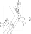
- Fig. 4 illustrates an enlarged view of the doors 230 according to the dotted square S2 in Fig. 2 .
- each of the doors 230 has protruding portions 231 which are respectively inserted into the two guiding rails 215 such that the doors 230 can move relative to the two guiding rails 215.
- the doors 230 further include bearings 233, the bearings 233 are respectively located at the protruding portions 231 and configured to respectively rotate in the two guiding rails 215.
- the protruding portions 231 and the bearings 233 are benefit for the doors 230 to move against the fixing bracket 210.
- each of doors 230 includes handles 234, and the handles 234 and the protruding portions 231 are respectively located at two corresponding sides of each door 230, the user can lift and move the doors 230 by the handles 234.
- the handles 234 When the users move the doors 230 or rotate the doors 230 relative to the protruding portions 231, the guiding rails 215 respectively support the protruding portions 231. Therefore, the protruding portions 231 are pivot points of the doors 230 as moving or rotating the doors 230, so as to save the users' strength.
- the guiding rails 215 are inverted U-shaped, and the guiding rails 215 are higher than and entirely above the top surface of the fixing bracket 210 and the through holes 211.
- Each of guiding rails 215 has two first portions 215a, and each of the two first portions 215a has a height which is relative to the top surface of the fixing bracket 210 or the through holes 211 gradually increasing toward a center of each guiding rail 215. Therefore, the first portions 215a are higher than the fixing bracket 210 and inclined relative to the top surface the fixing bracket 210.
- each guiding rail 215 has a second portion 215b, and the second portion 215b has a consistent height relative to the through holes 211 or the top surface of the fixing bracket 210, in which the second portion 215b which communicates with higher ends of the two first portions 215a is located between the two first portions 215a. Therefore, each of first portions 215a has the height relative to the top surface of the fixing bracket 210 gradually increasing toward the second portion 215b.
- each door 230 can move inclinedly along the corresponding first portion 215a, in which each door 230 can move vertically and horizontally along the corresponding first portion 215a. Each door 230 can also horizontally move along the second portion 215b of the corresponding guiding rail 215, and each door 230 can be pushed to move between the first portions 215a and the second portion 215b.
- the two doors 230 can move toward lowest ende of the corresponding first portions 215a such that the airtight cover 200 is in a closed state.
- One of the two doors 230 can move away from a lowest end of the corresponding first portions 215a such that the airtight cover 200 is in an open state.
- Each door 230 can move toward the corresponding through hole 211 to cover the corresponding through hole 211.
- Each door 230 can move away from the corresponding through holes 211 along the corresponding first portions 215a to leave the corresponding through hole 211.
- the two doors 230 are located at the lowest ends of the corresponding first portions 215a, and each door 230 is at a closed height such that the airtight cover 200 is in the closed state.
- one of the two doors 230 moves away from the corresponding through hole 211 along the first portion 215a to expose the corresponding through hole 211, and the one of the two doors 230 is located at the highest end of the corresponding first portion 215a or locate at the corresponding second portion 215b.
- one of the two doors 230 is at an open height which is relative to the top surface of the fixing bracket 210 and is greater than a thickness of another one of the two doors 230, and the airtight cover 200 is in the open state.
- one of the two doors 230 can move at the open height along the guiding rails 215 to be directly above another one of the doors 230 such that the two doors 230 are at least partially overlapped seeing from above.
- the two doors 230 are respectively at the open height and the closed height, the two doors 230 are substantially parallel to each other, and thus the necessary space for opening at least one of the two doors 230 or closing the two doors is small.
- the guiding slots 213 are lower than the second portions 215b of the guiding rails 215, and the guiding slots 213 are between the two first portions 215a. Therefore, when the doors 230 are located at the first portions 215a and at the closed height to cover the through holes 211, the pressuring handles 250 push against the guiding slots 213 to pressure the doors 230, so as to prevent the pressuring handles 250 from affecting the doors 230 as rotating.
- the present disclosure is not limited in this respect.
- each door 230 includes two sliding rails 235 which extend parallel to each other and two sliding blocks 237, and the two sliding rails 235 are located on a top surface of the corresponding door 230, the sliding blocks 237 are located at a bottom surface of the corresponding door 230. Moreover, the two sliding rails 235 extend from an edge of the corresponding door 230 to another edge of the corresponding door 230, and thus the two sliding rails 235 can fix the door 230 and increase the mechanical strength of the door 230. For instance, the two sliding rails 235 extend across two opposite sides of the corresponding door 230. Referring to Figs.
- one of the two doors 230 is moved to be above another one of the two doors 230 along the guiding rails 215, and the sliding blocks 237 of the one of the two doors 230 are respectively slidably connected to the two sliding rails 235 of the another one of the two doors 230 such that the two doors 230 can stack together and support mutually for moving horizontally relative to each other.
- wheels are respectively disposed at the sliding blocks 237 such that the two sliding blocks 237 can move on the two sliding rails 235 via the wheels.
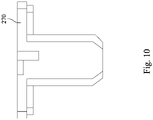
- the airtight cover 200 includes the fixing rod 270 which is detachably connected to the fixing bracket 210, and the fixing rod 270 is disposed between the two through holes 211 and crosses two opposite side of the through holes 211.
- the fixing rod 270 has a T-shaped cross section for fixing the two doors 230 to the fixing bracket 210 from above and lateral.
- the pressuring handles 250 are disposed on the fixing rod 270 to pressure the fixing rod 270, and the pressuring handles 250 can pressure the doors 230 through the fixing rod 270. Therefore, the airtight cover 200 can further provide outstanding airtight function, and the mechanical strength of the airtight cover 200 can be increased by using the combination of the pressuring handles 250 and the fixing rod 270.
- the airtight cover 200 includes a fixing lock 280 which has at least a portion disposed at a lateral side of the corresponding door 230 and configured to vertically move for fixing the corresponding door 230 to the fixing bracket 210.
- the fixing lock 280 includes a rotary hook 281 and a fixing hook 283, and the rotary hook 281 is configured to selectively fix the fixing hook 283 and is located at a lateral side the corresponding door 230.
- the fixing hook 283 is located on the fixing bracket 210 and is adjacent to an edge of the corresponding through hole 211.
- the rotary hook 281 includes a C-shaped portion 281a, an arm 281b, and a rotation pivot 281c, in which the C-shaped portion 281a is rotatably connected to the rotation pivot 281c, and the arm 281b is located at an end of the C-shaped portion 281a.
- the arm 281b is configured to be pushed to drive the C-shaped portion 281a to rotate relative to the rotation pivot 281c, and thus the C-shaped portion 281 a can further be fixed to or be separated from the fixing hook 283 such that the two doors 230 can be fixed to or be detachable from the fixing bracket 210.
- the users can easily rotate the fixing lock 280 along a vertical plane to lock the corresponding door 230 and fix the corresponding door 230 to the fixing bracket 210.
- the rotary hook 281 of the fixing lock 280 merely rotates along the vertical plane for fixing the fixing hook 283 such that the fixing lock 280 can save the necessary space to lock and fix the corresponding door 230.
- the airtight cover 200 does not include the sidewalls 214 and the guiding rails 215, and the doors 230 are detachably fixed to the fixing bracket 210. Therefore, the users can put the doors 230 which are separated from the fixing bracket 210 on the fixing bracket 210, and then the users can fix the doors 230 to the fixing bracket 210 via the fixing lock 280. The users can use the pressuring handles 250 to pressure the doors 230 such that the airtight cover 200 is in the airtight state.
- the users can further unlock the fixing lock 280, and the doors 230 are in a detachable state relative to the fixing bracket 210 such that the users can easily move the doors 230 away from the fixing bracket 210.
- the airtight cover 200 includes a connection rod 290, and the second sections 253 of the pressuring handles 250 are rotatably connected to the connection rod 290. Therefore, the users can push the connection rod 290 to simultaneously move the pressuring handles 250 for pressuring the doors 230 or releasing the pressures applied to the doors 230 such that the airtight cover 200 can efficiently switches to the airtight condition and prevent the air in the container 100 from leaking.
- an airtight device which has a container and an airtight cover is provided, and the airtight cover covers the container and prevents air or liquid from moving in or moving out of the container. Therefore, an object such as food and medicine stored in the container can be isolated from outside space, so as to prevent the air from leaking and prevent the food from decaying and being uneatable.
- the pressuring handles are located on the airtight cover, and the users can easily rotate the pressuring handles to make the airtight cover in the airtight state or release the airtight state.
Landscapes
- Engineering & Computer Science (AREA)
- Mechanical Engineering (AREA)
- Chemical & Material Sciences (AREA)
- Combustion & Propulsion (AREA)
- Physics & Mathematics (AREA)
- Thermal Sciences (AREA)
- General Engineering & Computer Science (AREA)
- Pressure Vessels And Lids Thereof (AREA)
- Accommodation For Nursing Or Treatment Tables (AREA)
Abstract
Description
- The present disclosure relates to an airtight device. More particularly, the present disclosure relates to an airtight device which can preserve objects.
- As technology progressing and spreading, storage devices, such as freezers, reefer containers, and refrigerators, are widely used to store food and medicine.
- In the process to store food and medicine, if the doors of the storage devices does not tightly close and generate a gap, the preservation ability will be negatively affected, so as to affect the expiration period of the food or the medicine. Therefore, the food or the medicine would decay or expire to be uneatable or unable to be taken, and this problem would lead to severe waste.
- It has become a critical issue about how to provide an airtight device which has tightly closed doors, so as to prevent air leaking and improve the preservation ability.
- In some embodiments of the present disclosure, an airtight device includes a container and an airtight cover disposed on the container, in which the airtight cover includes a fixing bracket, at least one door, and at least one pressuring handle. The fixing bracket has at least one through hole and at least one guiding slot, and the through hole communicates with an interior space of the container, the guiding slot includes a first top surface and a second top surface higher than the first top surface. The at least one door is configured to cover the through hole. The at least one pressuring handle which is pivoted to the door has a first section, a second section, and a rotation pivot between the first and second sections, in which the first section and the second section are configured to rotate relative to each other. The second section is configured to receive a force for driving the first section to move from below the second top surface to below the first top surface such that the rotation pivot pressures the door.
- In some embodiments of the present disclosure, the fixing bracket includes a guiding rail, and the door has a protruding portion inserted into the guiding rail. The guiding rail is above the through hole and has a first portion which has a height gradually increasing relative to the through hole, and the door is configured to move toward a lowest end of the first portion to be located at a closed height, and the door is also configured to move away from the lowest end of the first portion to be located at an open height.
- In some embodiments of the present disclosure, the guiding rail has a second portion which has a consistent height relative to the through hole and communicates with a higher end of the first portion.
- In some embodiments of the present disclosure, the door has a bearing which is disposed at the protruding portion.
- In some embodiments of the present disclosure, the airtight cover has a connection rod, and the at least one pressuring handle includes a plurality of the pressuring handles, the second sections of the pressuring handles are rotatably connected to the connection rod.
- In some embodiments of the present disclosure, the airtight cover has a fixing lock, and at least a portion of the fixing lock is disposed at a lateral side of the door, in which the fixing lock is configured to vertically move for locking the door on the fixing bracket.
- In some embodiments of the present disclosure, the at least one door includes two doors, and each of the two doors includes a sliding rail and a sliding block. One of the two doors is configured to move above another one of the two doors, and the sliding block of the one of the two doors is slidably connected to the sliding rail of the another one of the two doors.
- Another aspect of the present disclosure relates to an airtight device including a container, an airtight cover, and a fixing bracket. The airtight cover is disposed on the container, and the airtight cover includes a fixing bracket, two doors, and a plurality of pressuring handles. The fixing bracket has two through holes and a plurality of guiding slots, in which the two through holes communicate with an interior space of the container, and each of the guiding slots includes a first top surface and a second top surface higher than the first top surface. The two doors configured to cover the two through holes respectively. The plurality of pressuring handles are pivoted to the two door respectively, each of the pressuring handles having a first section, a second section, and a rotation pivot disposed between the first and second sections, in which the first section and the second section are configured to rotate relative to each other, and the second section is configured to receive a force for driving the first section to move from below the second top surface to below the first top surface such that the rotation pivot pressures a corresponding one of the two doors.
- In some embodiments of the present disclosure, the fixing bracket has a guiding rail, and each of the two doors has a protruding portion inserted into the siding rail. The guiding rail is above the two through holes and has two first portions, and each of the two first portions has a height gradually increasing relative to the two through holes. The two doors are configured to respectively move toward to be in a closed state, and the two doors are also configured to respectively move away from lowest ends of the two first portions to be in an open state.
- In some embodiments of the present disclosure, a second portion of the guiding rail has a consistent height relative to the two through holes, and the second portion which communicates with higher ends of the two first portions is located between the two first portions.
- In some embodiments of the present disclosure, each of the two doors has a bearing which is disposed at the protruding portion.
- In some embodiments of the present disclosure, the airtight cover includes a connection rod connected to the fixing bracket and disposed between the two through holes, and the connection rod has a T-shaped section which fixes the two doors from above and lateral.
- In some embodiments of the present disclosure, the airtight cover includes a fixing lock which has at least a portion disposed at a lateral side of the one of the two doors, and the fixing lock is configured to vertically move to fix the one of the two doors to the fixing bracket.
- In some embodiments of the present disclosure, each of the two doors includes a sliding rail and a sliding block, and one of the two doors is configured to move above another one of the two doors, the sliding block of the one of the two doors is slidably connected to the sliding rail of the another one of the two doors.
- In embodiment of the present disclosure, an airtight device which has a container and an airtight cover is provided, and the airtight cover covers the container and prevents air or liquid from moving in or moving out of the container. Therefore, an object such as food and medicine stored in the container can be isolated from outside space, so as to prevent the air from leaking and prevent the food from decaying and being uneatable. Moreover, the pressuring handles are located on the airtight cover, and the users can easily rotate the pressuring handles to make the airtight cover in the airtight state or release the airtight state.
- In embodiment of the present disclosure, an airtight device which has a container and an airtight cover is provided, and the airtight cover covers the container and prevents air or liquid from moving in or moving out of the container. Therefore, an object such as food and medicine stored in the container can be isolated from outside space, so as to prevent the air from leaking and prevent the food from decaying and being uneatable. Moreover, the pressuring handles are located on the airtight cover, and the users can easily rotate the pressuring handles to make the airtight cover in the airtight state or release the airtight state.
- The disclosure can be more fully understood by reading the following detailed description of the embodiment, with reference made to the accompanying drawings as follows:
-
Fig. 1 illustrates a schematic view of an airtight device in accordance with some embodiments of the present disclosure. -
Fig. 2 illustrates an exploded view of an airtight device in accordance with some embodiments of the present disclosure. -
Fig. 3 illustrates a partial enlarged view of a fixing bracket of an airtight cover according to the dotted square S1 in theFig. 2 . -
Fig. 4 illustrates a partial enlarged view of a door of an airtight cover according to the dotted square S2 in theFig. 2 . -
Fig. 5 illustrates a schematic view of an airtight cover which is in a pressurized state in accordance with some embodiments of the present disclosure. -
Fig. 6 illustrates a schematic view of an airtight cover which is in a depressurized state in accordance with some embodiments of the present disclosure. -
Fig. 7 illustrates an enlarged view according to the dotted square S3 in theFig. 5 . -
Fig. 8 illustrates an enlarged view according to the dotted square S4 in theFig. 6 . -
Fig. 9 illustrates a schematic view of the airtight cover which is in an airtight state. -
Fig. 10 illustrates a cross section view of a fixing rod drawn from a cross section line X inFig. 2 . - Reference will now be made in detail to the present embodiments of the invention, examples of which are illustrated in the accompanying drawings. Wherever possible, the same reference numbers are used in the drawings and the description to refer to the same or like parts.
- Reference is made to
Fig. 1 , which illustrates a schematic view of anairtight device 10. In some embodiments of the present disclosure, theairtight device 10 can include a freezer, a reefer container, or a refrigerator, in which theairtight device 10 includes acontainer 100 and anairtight cover 200. Theairtight cover 200 which is tightly disposed at anopening 110 of thecontainer 100 can entirely cover theopening 110 and seal thecontainer 100, so as to prevent air and liquid from moving in or out from thecontainer 100. Specifically, thecontainer 100 is a rectangular cabinet or a square cabinet, and thecontainer 100 can accommodate many types of objects, such as food and medicine. In addition, theairtight cover 200 can include afixing bracket 210, twodoors 230, and a plurality ofpressuring handles 250, in which users can rotate thepressuring handles 250 to apply pressures to thedoors 230 such that theairtight cover 200 is in an airtight condition. Next, the users can reversely rotate thepressuring handles 250 to release the pressures applied to thedoors 230 and release the airtight condition of theairtight cover 200. The related information and detail structure about theairtight cover 200 are introduced in the following paragraphs. In some embodiments of the present disclosure, theairtight cover 200 includes onesingle door 230, and the users can place thesingle door 230 against thefixing bracket 210 and use thepressuring handles 250 to apply pressures to thesingle door 230 such that theairtight cover 200 is in the airtight condition. - Please refer to
Figs. 1-3 .Fig. 2 illustrates an exploded view of theairtight cover 200.Fig. 3 illustrates an enlarged view of the fixingbracket 210 according to the dotted square S1 in theFig. 2 . In some embodiments of the present disclosure, the fixingbracket 210 has two throughholes 211 and a plurality of guidingslots 213, and the throughholes 211 communicates with an interior space of thecontainer 100. Therefore, the users can take an object from thecontainer 100 and put an object in thecontainer 100 via the throughholes 211 of theairtight cover 200. In addition, the users can move thedoors 230 to cover the throughholes 211 or leave the throughholes 211. The pressuring handles 250 are pivoted to periphery frames thedoors 230, and each of the pressuring handles 250 includes afirst section 251, asecond section 253, and arotation pivot 255 which is between thefirst section 251 and thesecond section 253, in which thefirst section 251 and thesecond section 253 are configured to rotate relative to each other. Moreover, each of the guidingslots 213 includes a firsttop surface 213a and a secondtop surface 213b adjacent to the firsttop surface 213a, and the secondtop surface 213b which is an interior top surface higher than the firsttop surface 213a which is another interior top surface. The firsttop surface 213a and the secondtop surface 213b can form a continuous surface which is a flat surface, an inclined surface, or a curved surface, and the firsttop surface 213a and the secondtop surface 213b can form an angle smaller than 90 degrees. In practical application, thefirst section 251 of each pressuring handle 250 can be pushed and inserted into the corresponding guidingslots 213. Refer toFigs. 5 and7, and Fig. 7 illustrates an enlarged view according to the dotted square S3 in theFig. 5 . When thefirst section 251 moves from below the secondtop surface 213b to below the firsttop surface 213a, thefirst section 251 is against the firsttop surface 213a to generate a reaction force for driving therotation pivot 255 and pressuring thedoors 230 such that theairtight cover 200 is in the airtight condition. Refer toFigs. 6 and8, and Fig. 8 illustrates an enlarged view according to the dotted square S4 inFig. 6 . When thefirst section 251 moves away from the firsttop surface 213a, the aforementioned reaction force which is generated by the firsttop surface 213a and applied to thefirst section 251 vanishes such that therotation pivot 255 releases the pressure applied to thecorresponding door 230 for leading theairtight cover 200 to release the airtight condition. For instance, when each pressuringhandle 250 is pushed to drive thefirst section 251 to move from below the firsttop surface 213a to below the secondtop surface 213b, the aforementioned reaction force which is generated by the firsttop surface 213a and is applied to thefirst section 251 vanishes. - Specifically, the fixing
bracket 210 can be made of metal, alloy, or polymer which has higher rigidity. For instance, the fixingbracket 210 is made of steel, aluminum metal, aluminum alloy, or plastic. In addition, the guidingslots 213 of the fixingbracket 210 can be manufactured by a machining process or a laser cutting process, but the present disclosure is not limited in this respect. Thedoors 230 are in shapes corresponding to shapes of the throughholes 211 of the fixingbracket 210, and thedoors 230 can be rectangular or square. The throughholes 211 can also be rectangular or square, and thedoors 230 are slightly greater than the throughholes 211. Therefore, when thedoors 230 respectively cover the throughholes 211, thedoors 230 can respectively entirely block the throughholes 211 from a top view. In addition, each of thedoors 230 includes the periphery frame and a transparent sheet surrounded by the periphery frame such that the users can see the interior space of thecontainer 100 through thedoors 230. The periphery frame can include metal, alloy, or polymer, such as steel, aluminum metal, aluminum alloy, and plastic which has higher rigidity. The transparent sheet can include transparent glass or transparent polymer, but the present disclosure is not limited in this respect. - In some embodiments of the present disclosure, the fixing
bracket 210 further includes twosidewalls 214 and two guidingrails 215, and the twosidewalls 214 which are respectively located at two corresponding sides of the throughholes 211 extend on a top surface of the fixingbracket 210. The guidingslots 213 and the two guidingrails 215 are at least located at a side where the twosidewalls 214 face the throughholes 211, and thedoors 230 are located between the twosidewalls 214 and slidably connected between the two guidingrails 215. In some other embodiments of the present disclosure, each of the guidingslots 213 and the two guidingrails 215 extends from a front surfaces of thecorresponding sidewall 214 which faces the throughholes 211 to a rear surfaces of thecorresponding sidewall 214 such that each of the pressuring handles 250 can smoothly rotate by receiving a force after thefirst section 251 is inserted into the corresponding guidingslot 213. The present disclosure is not limited in this respect. - Please refer to
Figs. 1-4 .Fig. 4 illustrates an enlarged view of thedoors 230 according to the dotted square S2 inFig. 2 . In some embodiments of the present disclosure, each of thedoors 230 has protrudingportions 231 which are respectively inserted into the two guidingrails 215 such that thedoors 230 can move relative to the two guidingrails 215. In addition, thedoors 230 further includebearings 233, thebearings 233 are respectively located at the protrudingportions 231 and configured to respectively rotate in the two guidingrails 215. In practical application, the protrudingportions 231 and thebearings 233 are benefit for thedoors 230 to move against the fixingbracket 210. - In some embodiments of the present disclosure, each of
doors 230 includeshandles 234, and thehandles 234 and the protrudingportions 231 are respectively located at two corresponding sides of eachdoor 230, the user can lift and move thedoors 230 by thehandles 234. When the users move thedoors 230 or rotate thedoors 230 relative to the protrudingportions 231, the guidingrails 215 respectively support the protrudingportions 231. Therefore, the protrudingportions 231 are pivot points of thedoors 230 as moving or rotating thedoors 230, so as to save the users' strength. - Specifically, the guiding
rails 215 are inverted U-shaped, and the guidingrails 215 are higher than and entirely above the top surface of the fixingbracket 210 and the throughholes 211. Each of guidingrails 215 has twofirst portions 215a, and each of the twofirst portions 215a has a height which is relative to the top surface of the fixingbracket 210 or the throughholes 211 gradually increasing toward a center of each guidingrail 215. Therefore, thefirst portions 215a are higher than the fixingbracket 210 and inclined relative to the top surface the fixingbracket 210. In addition, each guidingrail 215 has asecond portion 215b, and thesecond portion 215b has a consistent height relative to the throughholes 211 or the top surface of the fixingbracket 210, in which thesecond portion 215b which communicates with higher ends of the twofirst portions 215a is located between the twofirst portions 215a. Therefore, each offirst portions 215a has the height relative to the top surface of the fixingbracket 210 gradually increasing toward thesecond portion 215b. In addition, eachdoor 230 can move inclinedly along the correspondingfirst portion 215a, in which eachdoor 230 can move vertically and horizontally along the correspondingfirst portion 215a. Eachdoor 230 can also horizontally move along thesecond portion 215b of the corresponding guidingrail 215, and eachdoor 230 can be pushed to move between thefirst portions 215a and thesecond portion 215b. - In practical application, the two
doors 230 can move toward lowest ende of the correspondingfirst portions 215a such that theairtight cover 200 is in a closed state. One of the twodoors 230 can move away from a lowest end of the correspondingfirst portions 215a such that theairtight cover 200 is in an open state. Eachdoor 230 can move toward the corresponding throughhole 211 to cover the corresponding throughhole 211. Eachdoor 230 can move away from the corresponding throughholes 211 along the correspondingfirst portions 215a to leave the corresponding throughhole 211. Referring toFigs. 5 and6 , the twodoors 230 are located at the lowest ends of the correspondingfirst portions 215a, and eachdoor 230 is at a closed height such that theairtight cover 200 is in the closed state. Referring toFig. 9 , one of the twodoors 230 moves away from the corresponding throughhole 211 along thefirst portion 215a to expose the corresponding throughhole 211, and the one of the twodoors 230 is located at the highest end of the correspondingfirst portion 215a or locate at the correspondingsecond portion 215b. In addition, one of the twodoors 230 is at an open height which is relative to the top surface of the fixingbracket 210 and is greater than a thickness of another one of the twodoors 230, and theairtight cover 200 is in the open state. Therefore, one of the twodoors 230 can move at the open height along the guidingrails 215 to be directly above another one of thedoors 230 such that the twodoors 230 are at least partially overlapped seeing from above. When the twodoors 230 are respectively at the open height and the closed height, the twodoors 230 are substantially parallel to each other, and thus the necessary space for opening at least one of the twodoors 230 or closing the two doors is small. - In some embodiments of the present disclosure, the guiding
slots 213 are lower than thesecond portions 215b of the guidingrails 215, and the guidingslots 213 are between the twofirst portions 215a. Therefore, when thedoors 230 are located at thefirst portions 215a and at the closed height to cover the throughholes 211, the pressuring handles 250 push against the guidingslots 213 to pressure thedoors 230, so as to prevent the pressuring handles 250 from affecting thedoors 230 as rotating. The present disclosure is not limited in this respect. - In some embodiments of the present disclosure, each
door 230 includes two slidingrails 235 which extend parallel to each other and two slidingblocks 237, and the two slidingrails 235 are located on a top surface of thecorresponding door 230, the slidingblocks 237 are located at a bottom surface of thecorresponding door 230. Moreover, the two slidingrails 235 extend from an edge of thecorresponding door 230 to another edge of thecorresponding door 230, and thus the two slidingrails 235 can fix thedoor 230 and increase the mechanical strength of thedoor 230. For instance, the two slidingrails 235 extend across two opposite sides of thecorresponding door 230. Referring toFigs. 6 and9 , one of the twodoors 230 is moved to be above another one of the twodoors 230 along the guidingrails 215, and the slidingblocks 237 of the one of the twodoors 230 are respectively slidably connected to the two slidingrails 235 of the another one of the twodoors 230 such that the twodoors 230 can stack together and support mutually for moving horizontally relative to each other. Specifically, wheels are respectively disposed at the slidingblocks 237 such that the two slidingblocks 237 can move on the two slidingrails 235 via the wheels. - Please refer to
Fig. 10 which illustrates a cross section view of a fixingrod 270 taken from a cross section line X inFig 2 . In some embodiments of the present disclosure, theairtight cover 200 includes the fixingrod 270 which is detachably connected to the fixingbracket 210, and the fixingrod 270 is disposed between the two throughholes 211 and crosses two opposite side of the throughholes 211. The fixingrod 270 has a T-shaped cross section for fixing the twodoors 230 to the fixingbracket 210 from above and lateral. In addition, the pressuring handles 250 are disposed on the fixingrod 270 to pressure the fixingrod 270, and the pressuring handles 250 can pressure thedoors 230 through the fixingrod 270. Therefore, theairtight cover 200 can further provide outstanding airtight function, and the mechanical strength of theairtight cover 200 can be increased by using the combination of the pressuring handles 250 and the fixingrod 270. - Please refer to
Figs. 2-3 . In some embodiments of the present disclosure, theairtight cover 200 includes a fixinglock 280 which has at least a portion disposed at a lateral side of thecorresponding door 230 and configured to vertically move for fixing thecorresponding door 230 to the fixingbracket 210. In addition, the fixinglock 280 includes arotary hook 281 and a fixinghook 283, and therotary hook 281 is configured to selectively fix the fixinghook 283 and is located at a lateral side thecorresponding door 230. In addition, the fixinghook 283 is located on the fixingbracket 210 and is adjacent to an edge of the corresponding throughhole 211. Specifically, therotary hook 281 includes a C-shapedportion 281a, anarm 281b, and arotation pivot 281c, in which the C-shapedportion 281a is rotatably connected to therotation pivot 281c, and thearm 281b is located at an end of the C-shapedportion 281a. Thearm 281b is configured to be pushed to drive the C-shapedportion 281a to rotate relative to therotation pivot 281c, and thus the C-shapedportion 281 a can further be fixed to or be separated from the fixinghook 283 such that the twodoors 230 can be fixed to or be detachable from the fixingbracket 210. Therefore, the users can easily rotate the fixinglock 280 along a vertical plane to lock thecorresponding door 230 and fix thecorresponding door 230 to the fixingbracket 210. In comparison with normal fixing structures, therotary hook 281 of the fixinglock 280 merely rotates along the vertical plane for fixing the fixinghook 283 such that the fixinglock 280 can save the necessary space to lock and fix thecorresponding door 230. - In other embodiments of the present disclosure, the
airtight cover 200 does not include thesidewalls 214 and the guidingrails 215, and thedoors 230 are detachably fixed to the fixingbracket 210. Therefore, the users can put thedoors 230 which are separated from the fixingbracket 210 on the fixingbracket 210, and then the users can fix thedoors 230 to the fixingbracket 210 via the fixinglock 280. The users can use the pressuring handles 250 to pressure thedoors 230 such that theairtight cover 200 is in the airtight state. Moreover, after the users release the airtight state of theairtight cover 200 by using pressuring handles 250, the users can further unlock the fixinglock 280, and thedoors 230 are in a detachable state relative to the fixingbracket 210 such that the users can easily move thedoors 230 away from the fixingbracket 210. - Please refer to
Figs. 5-8 . In some embodiments of the present disclosure, theairtight cover 200 includes aconnection rod 290, and thesecond sections 253 of the pressuring handles 250 are rotatably connected to theconnection rod 290. Therefore, the users can push theconnection rod 290 to simultaneously move the pressuring handles 250 for pressuring thedoors 230 or releasing the pressures applied to thedoors 230 such that theairtight cover 200 can efficiently switches to the airtight condition and prevent the air in thecontainer 100 from leaking. - In embodiment of the present disclosure, an airtight device which has a container and an airtight cover is provided, and the airtight cover covers the container and prevents air or liquid from moving in or moving out of the container. Therefore, an object such as food and medicine stored in the container can be isolated from outside space, so as to prevent the air from leaking and prevent the food from decaying and being uneatable. Moreover, the pressuring handles are located on the airtight cover, and the users can easily rotate the pressuring handles to make the airtight cover in the airtight state or release the airtight state.
Claims (14)
- An airtight device (10) characterized by comprising:a container (100); andan airtight cover (200) disposed on the container (100), wherein the airtight cover (200) comprises:a fixing bracket (210) having at least one through hole (211) and at least one guiding slot (213), wherein the through hole (211) communicates with an interior space of the container (100), the guiding slot (213) comprises a first top surface (213a) and a second top surface (213b) higher than the first top surface (213a);at least one door (230) configured to cover the through hole (211); andat least one pressuring handle (250) pivoted to the door (230), the pressuring handle (250) having a first section (251), a second section (253), and a rotation pivot (255) disposed between the first and second sections (251, 253), wherein the first section (251) and the second section (253) are configured to rotate relative to each other, and wherein the second section (253) is configured to receive a force for driving the first section (251) to move from below the second top surface (213b) to below the first top surface (213a) such that the rotation pivot (255) pressures the door (230).
- The airtight device (10) of claim 1, wherein the fixing bracket (210) comprises a guiding rail (215), the door (230) has a protruding portion (231) inserted into the guiding rail (215), and the guiding rail (215) is above the through hole (211) and has a first portion (215a) which has a height gradually increasing relative to the through hole (211), and wherein the door (230) is configured to move toward a lowest end of the first portion (215a) to be located at a closed height, and the door (230) is also configured to move away from the lowest end of the first portion (215a) to be located at an open height.
- The airtight device (10) of claim 2, wherein the guiding rail (215) has a second portion (215b) which has a consistent height relative to the through hole (211) and communicates with a higher end of the first portion (215a).
- The airtight device (10) of claim 2, wherein the door (230) has a bearing (233) disposed at the protruding portion (231).
- The airtight device (10) of claim 1, wherein the airtight cover (200) has a connection rod (290), and the at least one pressuring handle (250) includes a plurality of the pressuring handles (250), the second sections (253) of the pressuring handles (250) are rotatably connected to the connection rod (290).
- The airtight device (10) of claim 1, wherein the airtight cover (200) has a fixing lock (280), at least a portion of the fixing lock (280) is disposed at a lateral side of the door (230), and wherein the fixing lock (280) is configured to vertically move for locking the door (230) on the fixing bracket (210).
- The airtight device (10) of claim 1, wherein the at least one door (230) includes two doors (230), each of the two doors (230) includes a sliding rail (235) and a sliding block (237), and one of the two doors (230) is configured to move above another one of the two doors (230), the sliding block (237) of the one of the two doors (230) is slidably connected to the sliding rail (235) of the another one of the two doors (230).
- An airtight device (10) characterized by comprising:a container (100); andan airtight cover (200) disposed on the container (100), wherein the airtight cover (200) comprises:a fixing bracket (210) having two through holes (211) and a plurality of guiding slots (213), wherein the two through holes (211) communicate with an interior space of the container (100), each of the guiding slots (213) comprises a first top surface (213a) and a second top surface (213b) higher than the first top surface (213a);two doors (230) configured to cover the two through holes (211) respectively; anda plurality of pressuring handles (250) pivoted to the two doors (230) respectively, each of the pressuring handles (250) having a first section (251), a second section (253), and a rotation pivot (255) disposed between the first and second sections (251, 253), wherein the first section (251) and the second section (253) are configured to rotate relative to each other, and wherein the second section (253) is configured to receive a force for driving the first section (251) to move from below the second top surface (213b) to below the first top surface (213a) such that the rotation pivot (255) pressures a corresponding one of the two doors (230).
- The airtight device (10) of claim 8, wherein the fixing bracket (210) has a guiding rail (215), each of the two doors (230) has a protruding portion (231) inserted into the guiding rail (215), and the guiding rail (215) is above the two through holes (211) and has two first portions (215a), each of the two first portions (215a) has a height gradually increasing relative to the two through holes (211), and wherein the two doors (230) are configured to respectively move toward lowest ends of the two first portions (215a) to be in a closed state, and the two doors (230) are also configured to respectively move away from the lowest ends of the two first portions (215a) to be in an open state.
- The airtight device (10) of claim 9, wherein a second portion (215b) of the guiding rail (215) has a consistent height relative to the two through holes (211), and the second portion (215b) which communicates with higher ends of the two first portions (215a) is located between the two first portions (215a).
- The airtight device (10) of claim 9, wherein each of the two doors (230) has a bearing (233) disposed at the protruding portion (231).
- The airtight device (10) of claim 8, wherein the airtight cover (200) comprises a connection rod (290) connected to the fixing bracket (210) and disposed between the two through holes (211), and wherein the connection rod (290) has a T-shaped section which fixes the two doors (230) from above and lateral.
- The airtight device (10) of claim 8, wherein the airtight cover (200) comprises a fixing lock (280) which has at least a portion disposed at a lateral side of the one of the two doors (230), and the fixing lock (280) is configured to vertically move to fix the one of the two doors (230) to the fixing bracket (210).
- The airtight device (10) of claim 8, wherein each of the two doors (230) includes a sliding rail (235) and a sliding block (237), and wherein one of the two doors (230) is configured to move above another one of the two doors (230), the sliding block (237) of the one of the two doors (230) is slidably connected to the sliding rail (235) of the another one of the two doors (230).
Applications Claiming Priority (2)
| Application Number | Priority Date | Filing Date | Title |
|---|---|---|---|
| US202163203870P | 2021-08-03 | 2021-08-03 | |
| CN202111567734.4A CN115875917B (en) | 2021-08-03 | 2021-12-21 | Air-tight device |
Publications (3)
| Publication Number | Publication Date |
|---|---|
| EP4129880A1 true EP4129880A1 (en) | 2023-02-08 |
| EP4129880B1 EP4129880B1 (en) | 2024-08-07 |
| EP4129880C0 EP4129880C0 (en) | 2024-08-07 |
Family
ID=81307307
Family Applications (1)
| Application Number | Title | Priority Date | Filing Date |
|---|---|---|---|
| EP22169213.0A Active EP4129880B1 (en) | 2021-08-03 | 2022-04-21 | Airtight device |
Country Status (2)
| Country | Link |
|---|---|
| US (1) | US11772858B2 (en) |
| EP (1) | EP4129880B1 (en) |
Families Citing this family (1)
| Publication number | Priority date | Publication date | Assignee | Title |
|---|---|---|---|---|
| TWI888849B (en) * | 2023-06-15 | 2025-07-01 | 台達電子工業股份有限公司 | Immersion cooling system with airtight link latch cover structure |
Citations (2)
| Publication number | Priority date | Publication date | Assignee | Title |
|---|---|---|---|---|
| KR20090058979A (en) * | 2007-12-05 | 2009-06-10 | 엘지전자 주식회사 | Airtight containers |
| KR20150009689A (en) * | 2013-07-17 | 2015-01-27 | 문영민 | An airtight container |
Family Cites Families (16)
| Publication number | Priority date | Publication date | Assignee | Title |
|---|---|---|---|---|
| US1118435A (en) * | 1914-04-09 | 1914-11-24 | Mosler Safe Co | Fireproof safe. |
| US1709520A (en) * | 1928-03-09 | 1929-04-16 | Glacifer Corp | Shipping container |
| US1808403A (en) * | 1928-04-19 | 1931-06-02 | Axel A Eklund | Latching means for removable crank case covers |
| US4547006A (en) * | 1978-06-22 | 1985-10-15 | Superior S.A. | Luggage closing device |
| US5601206A (en) * | 1995-06-06 | 1997-02-11 | Rubbermaid Specialty Products, Inc. | Truck box |
| US6079585A (en) * | 1998-09-14 | 2000-06-27 | Lentini; Robert | Truck box with improved operating rod |
| US6502868B1 (en) * | 2000-09-01 | 2003-01-07 | Protech Industries, Inc. | Dual T-lock apparatus |
| ATE269013T1 (en) * | 2000-10-19 | 2004-07-15 | Parat Werk Schoenenbach Gmbh | CLOSURE DEVICE FOR A CONTAINER AND CONTAINER EQUIPPED WITH THE CLOSURE DEVICE |
| KR101819004B1 (en) | 2015-02-13 | 2018-01-16 | 엘지전자 주식회사 | Refrigerator |
| JP6873657B2 (en) * | 2016-10-25 | 2021-05-19 | キヤノン株式会社 | Seat support device and image forming device |
| CN107269173A (en) | 2017-07-28 | 2017-10-20 | 荣阳铝业(中国)有限公司 | A kind of easy unlatching and close tight sliding door |
| CN108426401B (en) | 2018-01-19 | 2020-09-29 | 青岛海尔股份有限公司 | refrigerator |
| JP7293054B2 (en) | 2019-09-10 | 2023-06-19 | 株式会社オカムラ | Partition panel with door |
| CN212428465U (en) | 2020-08-12 | 2021-01-29 | 宁波锐驰科技有限公司 | Simple translational sealing window |
| TWI731778B (en) * | 2020-08-27 | 2021-06-21 | 緯穎科技服務股份有限公司 | Liftable hinge mechanism and related airtight device for preventing gaseous matter from leakage |
| CN213573695U (en) | 2020-09-17 | 2021-06-29 | 中科圣杰(深圳)科技集团有限公司 | Delivery window with rotary handle |
-
2022
- 2022-04-01 US US17/657,629 patent/US11772858B2/en active Active
- 2022-04-21 EP EP22169213.0A patent/EP4129880B1/en active Active
Patent Citations (2)
| Publication number | Priority date | Publication date | Assignee | Title |
|---|---|---|---|---|
| KR20090058979A (en) * | 2007-12-05 | 2009-06-10 | 엘지전자 주식회사 | Airtight containers |
| KR20150009689A (en) * | 2013-07-17 | 2015-01-27 | 문영민 | An airtight container |
Also Published As
| Publication number | Publication date |
|---|---|
| US11772858B2 (en) | 2023-10-03 |
| US20230040488A1 (en) | 2023-02-09 |
| EP4129880B1 (en) | 2024-08-07 |
| EP4129880C0 (en) | 2024-08-07 |
Similar Documents
| Publication | Publication Date | Title |
|---|---|---|
| JP4808193B2 (en) | refrigerator | |
| EP2059751B1 (en) | Refrigerator with an apparatus for preventing leakage of cooling air | |
| JP4981165B2 (en) | Refrigerator with double storage door | |
| US8454103B2 (en) | Refrigerator | |
| KR20110064720A (en) | Refrigerator | |
| EP4129880B1 (en) | Airtight device | |
| JP2009036453A (en) | refrigerator | |
| KR101741392B1 (en) | Refrigerator comprising shelf which is automatically drawn out | |
| JP5002362B2 (en) | refrigerator | |
| JP4423320B2 (en) | refrigerator | |
| CN106322901B (en) | Side by side combination refrigerator and its vertical beam guider | |
| US20240191935A1 (en) | Refrigerator | |
| CN115875917B (en) | Air-tight device | |
| CN115246526B (en) | Cover components and packaging box | |
| CN2869715Y (en) | Store box of refrigerator and refrigerator with same | |
| CN219651840U (en) | Polyurethane material storage box with heat insulation and heat preservation functions | |
| JP2003302150A (en) | refrigerator | |
| CN218668876U (en) | Refrigeration device | |
| JPH07213355A (en) | Rack device for storage box | |
| CN206056090U (en) | Side by side combination refrigerator and its vertical beam guider | |
| CN219525086U (en) | Storage goods shelves dust keeper | |
| JP5792656B2 (en) | refrigerator | |
| US12359867B2 (en) | Door storage assembly | |
| CN215423552U (en) | Compact shelf with anti-theft function | |
| CN2716763Y (en) | Novel horizontal refrigerator |
Legal Events
| Date | Code | Title | Description |
|---|---|---|---|
| PUAI | Public reference made under article 153(3) epc to a published international application that has entered the european phase |
Free format text: ORIGINAL CODE: 0009012 |
|
| STAA | Information on the status of an ep patent application or granted ep patent |
Free format text: STATUS: THE APPLICATION HAS BEEN PUBLISHED |
|
| AK | Designated contracting states |
Kind code of ref document: A1 Designated state(s): AL AT BE BG CH CY CZ DE DK EE ES FI FR GB GR HR HU IE IS IT LI LT LU LV MC MK MT NL NO PL PT RO RS SE SI SK SM TR |
|
| STAA | Information on the status of an ep patent application or granted ep patent |
Free format text: STATUS: REQUEST FOR EXAMINATION WAS MADE |
|
| 17P | Request for examination filed |
Effective date: 20230711 |
|
| RBV | Designated contracting states (corrected) |
Designated state(s): AL AT BE BG CH CY CZ DE DK EE ES FI FR GB GR HR HU IE IS IT LI LT LU LV MC MK MT NL NO PL PT RO RS SE SI SK SM TR |
|
| GRAP | Despatch of communication of intention to grant a patent |
Free format text: ORIGINAL CODE: EPIDOSNIGR1 |
|
| STAA | Information on the status of an ep patent application or granted ep patent |
Free format text: STATUS: GRANT OF PATENT IS INTENDED |
|
| RIC1 | Information provided on ipc code assigned before grant |
Ipc: A47F 3/04 20060101ALN20240313BHEP Ipc: B65D 43/00 20060101ALI20240313BHEP Ipc: A47J 47/02 20060101ALI20240313BHEP Ipc: A47F 1/00 20060101ALI20240313BHEP Ipc: B66C 7/04 20060101AFI20240313BHEP |
|
| INTG | Intention to grant announced |
Effective date: 20240409 |
|
| GRAS | Grant fee paid |
Free format text: ORIGINAL CODE: EPIDOSNIGR3 |
|
| GRAA | (expected) grant |
Free format text: ORIGINAL CODE: 0009210 |
|
| STAA | Information on the status of an ep patent application or granted ep patent |
Free format text: STATUS: THE PATENT HAS BEEN GRANTED |
|
| AK | Designated contracting states |
Kind code of ref document: B1 Designated state(s): AL AT BE BG CH CY CZ DE DK EE ES FI FR GB GR HR HU IE IS IT LI LT LU LV MC MK MT NL NO PL PT RO RS SE SI SK SM TR |
|
| REG | Reference to a national code |
Ref country code: GB Ref legal event code: FG4D |
|
| REG | Reference to a national code |
Ref country code: CH Ref legal event code: EP |
|
| REG | Reference to a national code |
Ref country code: IE Ref legal event code: FG4D |
|
| REG | Reference to a national code |
Ref country code: DE Ref legal event code: R096 Ref document number: 602022005075 Country of ref document: DE |
|
| U01 | Request for unitary effect filed |
Effective date: 20240903 |
|
| U07 | Unitary effect registered |
Designated state(s): AT BE BG DE DK EE FI FR IT LT LU LV MT NL PT RO SE SI Effective date: 20240916 |
|
| PG25 | Lapsed in a contracting state [announced via postgrant information from national office to epo] |
Ref country code: NO Free format text: LAPSE BECAUSE OF FAILURE TO SUBMIT A TRANSLATION OF THE DESCRIPTION OR TO PAY THE FEE WITHIN THE PRESCRIBED TIME-LIMIT Effective date: 20241107 |
|
| PG25 | Lapsed in a contracting state [announced via postgrant information from national office to epo] |
Ref country code: GR Free format text: LAPSE BECAUSE OF FAILURE TO SUBMIT A TRANSLATION OF THE DESCRIPTION OR TO PAY THE FEE WITHIN THE PRESCRIBED TIME-LIMIT Effective date: 20241108 Ref country code: PL Free format text: LAPSE BECAUSE OF FAILURE TO SUBMIT A TRANSLATION OF THE DESCRIPTION OR TO PAY THE FEE WITHIN THE PRESCRIBED TIME-LIMIT Effective date: 20240807 |
|
| PG25 | Lapsed in a contracting state [announced via postgrant information from national office to epo] |
Ref country code: IS Free format text: LAPSE BECAUSE OF FAILURE TO SUBMIT A TRANSLATION OF THE DESCRIPTION OR TO PAY THE FEE WITHIN THE PRESCRIBED TIME-LIMIT Effective date: 20241207 |
|
| PG25 | Lapsed in a contracting state [announced via postgrant information from national office to epo] |
Ref country code: HR Free format text: LAPSE BECAUSE OF FAILURE TO SUBMIT A TRANSLATION OF THE DESCRIPTION OR TO PAY THE FEE WITHIN THE PRESCRIBED TIME-LIMIT Effective date: 20240807 |
|
| PG25 | Lapsed in a contracting state [announced via postgrant information from national office to epo] |
Ref country code: ES Free format text: LAPSE BECAUSE OF FAILURE TO SUBMIT A TRANSLATION OF THE DESCRIPTION OR TO PAY THE FEE WITHIN THE PRESCRIBED TIME-LIMIT Effective date: 20240807 Ref country code: RS Free format text: LAPSE BECAUSE OF FAILURE TO SUBMIT A TRANSLATION OF THE DESCRIPTION OR TO PAY THE FEE WITHIN THE PRESCRIBED TIME-LIMIT Effective date: 20241107 |
|
| PG25 | Lapsed in a contracting state [announced via postgrant information from national office to epo] |
Ref country code: RS Free format text: LAPSE BECAUSE OF FAILURE TO SUBMIT A TRANSLATION OF THE DESCRIPTION OR TO PAY THE FEE WITHIN THE PRESCRIBED TIME-LIMIT Effective date: 20241107 Ref country code: PL Free format text: LAPSE BECAUSE OF FAILURE TO SUBMIT A TRANSLATION OF THE DESCRIPTION OR TO PAY THE FEE WITHIN THE PRESCRIBED TIME-LIMIT Effective date: 20240807 Ref country code: NO Free format text: LAPSE BECAUSE OF FAILURE TO SUBMIT A TRANSLATION OF THE DESCRIPTION OR TO PAY THE FEE WITHIN THE PRESCRIBED TIME-LIMIT Effective date: 20241107 Ref country code: IS Free format text: LAPSE BECAUSE OF FAILURE TO SUBMIT A TRANSLATION OF THE DESCRIPTION OR TO PAY THE FEE WITHIN THE PRESCRIBED TIME-LIMIT Effective date: 20241207 Ref country code: HR Free format text: LAPSE BECAUSE OF FAILURE TO SUBMIT A TRANSLATION OF THE DESCRIPTION OR TO PAY THE FEE WITHIN THE PRESCRIBED TIME-LIMIT Effective date: 20240807 Ref country code: GR Free format text: LAPSE BECAUSE OF FAILURE TO SUBMIT A TRANSLATION OF THE DESCRIPTION OR TO PAY THE FEE WITHIN THE PRESCRIBED TIME-LIMIT Effective date: 20241108 Ref country code: ES Free format text: LAPSE BECAUSE OF FAILURE TO SUBMIT A TRANSLATION OF THE DESCRIPTION OR TO PAY THE FEE WITHIN THE PRESCRIBED TIME-LIMIT Effective date: 20240807 |
|
| PG25 | Lapsed in a contracting state [announced via postgrant information from national office to epo] |
Ref country code: SM Free format text: LAPSE BECAUSE OF FAILURE TO SUBMIT A TRANSLATION OF THE DESCRIPTION OR TO PAY THE FEE WITHIN THE PRESCRIBED TIME-LIMIT Effective date: 20240807 |
|
| U20 | Renewal fee for the european patent with unitary effect paid |
Year of fee payment: 4 Effective date: 20250310 |
|
| PG25 | Lapsed in a contracting state [announced via postgrant information from national office to epo] |
Ref country code: CZ Free format text: LAPSE BECAUSE OF FAILURE TO SUBMIT A TRANSLATION OF THE DESCRIPTION OR TO PAY THE FEE WITHIN THE PRESCRIBED TIME-LIMIT Effective date: 20240807 |
|
| PG25 | Lapsed in a contracting state [announced via postgrant information from national office to epo] |
Ref country code: SK Free format text: LAPSE BECAUSE OF FAILURE TO SUBMIT A TRANSLATION OF THE DESCRIPTION OR TO PAY THE FEE WITHIN THE PRESCRIBED TIME-LIMIT Effective date: 20240807 |
|
| PLBE | No opposition filed within time limit |
Free format text: ORIGINAL CODE: 0009261 |
|
| STAA | Information on the status of an ep patent application or granted ep patent |
Free format text: STATUS: NO OPPOSITION FILED WITHIN TIME LIMIT |
|
| 26N | No opposition filed |
Effective date: 20250508 |
|
| REG | Reference to a national code |
Ref country code: CH Ref legal event code: H13 Free format text: ST27 STATUS EVENT CODE: U-0-0-H10-H13 (AS PROVIDED BY THE NATIONAL OFFICE) Effective date: 20251125 |
|
| PG25 | Lapsed in a contracting state [announced via postgrant information from national office to epo] |
Ref country code: MC Free format text: LAPSE BECAUSE OF FAILURE TO SUBMIT A TRANSLATION OF THE DESCRIPTION OR TO PAY THE FEE WITHIN THE PRESCRIBED TIME-LIMIT Effective date: 20240807 |
|
| PG25 | Lapsed in a contracting state [announced via postgrant information from national office to epo] |
Ref country code: CH Free format text: LAPSE BECAUSE OF NON-PAYMENT OF DUE FEES Effective date: 20250430 |
|
| PG25 | Lapsed in a contracting state [announced via postgrant information from national office to epo] |
Ref country code: IE Free format text: LAPSE BECAUSE OF NON-PAYMENT OF DUE FEES Effective date: 20250421 |
|
| U20 | Renewal fee for the european patent with unitary effect paid |
Year of fee payment: 5 Effective date: 20260310 |