EP4129855A1 - Drone transport container - Google Patents
Drone transport container Download PDFInfo
- Publication number
- EP4129855A1 EP4129855A1 EP20929034.5A EP20929034A EP4129855A1 EP 4129855 A1 EP4129855 A1 EP 4129855A1 EP 20929034 A EP20929034 A EP 20929034A EP 4129855 A1 EP4129855 A1 EP 4129855A1
- Authority
- EP
- European Patent Office
- Prior art keywords
- outer container
- load
- cushioning portion
- container
- delivery
- Prior art date
- Legal status (The legal status is an assumption and is not a legal conclusion. Google has not performed a legal analysis and makes no representation as to the accuracy of the status listed.)
- Pending
Links
Images





Classifications
-
- B—PERFORMING OPERATIONS; TRANSPORTING
- B65—CONVEYING; PACKING; STORING; HANDLING THIN OR FILAMENTARY MATERIAL
- B65D—CONTAINERS FOR STORAGE OR TRANSPORT OF ARTICLES OR MATERIALS, e.g. BAGS, BARRELS, BOTTLES, BOXES, CANS, CARTONS, CRATES, DRUMS, JARS, TANKS, HOPPERS, FORWARDING CONTAINERS; ACCESSORIES, CLOSURES, OR FITTINGS THEREFOR; PACKAGING ELEMENTS; PACKAGES
- B65D81/00—Containers, packaging elements, or packages, for contents presenting particular transport or storage problems, or adapted to be used for non-packaging purposes after removal of contents
- B65D81/02—Containers, packaging elements, or packages, for contents presenting particular transport or storage problems, or adapted to be used for non-packaging purposes after removal of contents specially adapted to protect contents from mechanical damage
- B65D81/05—Containers, packaging elements, or packages, for contents presenting particular transport or storage problems, or adapted to be used for non-packaging purposes after removal of contents specially adapted to protect contents from mechanical damage maintaining contents at spaced relation from package walls, or from other contents
- B65D81/051—Containers, packaging elements, or packages, for contents presenting particular transport or storage problems, or adapted to be used for non-packaging purposes after removal of contents specially adapted to protect contents from mechanical damage maintaining contents at spaced relation from package walls, or from other contents using pillow-like elements filled with cushioning material, e.g. elastic foam, fabric
- B65D81/052—Containers, packaging elements, or packages, for contents presenting particular transport or storage problems, or adapted to be used for non-packaging purposes after removal of contents specially adapted to protect contents from mechanical damage maintaining contents at spaced relation from package walls, or from other contents using pillow-like elements filled with cushioning material, e.g. elastic foam, fabric filled with fluid, e.g. inflatable elements
-
- B—PERFORMING OPERATIONS; TRANSPORTING
- B64—AIRCRAFT; AVIATION; COSMONAUTICS
- B64D—EQUIPMENT FOR FITTING IN OR TO AIRCRAFT; FLIGHT SUITS; PARACHUTES; ARRANGEMENT OR MOUNTING OF POWER PLANTS OR PROPULSION TRANSMISSIONS IN AIRCRAFT
- B64D1/00—Dropping, ejecting, releasing or receiving articles, liquids, or the like, in flight
- B64D1/02—Dropping, ejecting, or releasing articles
- B64D1/08—Dropping, ejecting, or releasing articles the articles being load-carrying devices
- B64D1/14—Absorbing landing shocks
-
- B—PERFORMING OPERATIONS; TRANSPORTING
- B64—AIRCRAFT; AVIATION; COSMONAUTICS
- B64D—EQUIPMENT FOR FITTING IN OR TO AIRCRAFT; FLIGHT SUITS; PARACHUTES; ARRANGEMENT OR MOUNTING OF POWER PLANTS OR PROPULSION TRANSMISSIONS IN AIRCRAFT
- B64D9/00—Equipment for handling freight; Equipment for facilitating passenger embarkation or the like
-
- B—PERFORMING OPERATIONS; TRANSPORTING
- B65—CONVEYING; PACKING; STORING; HANDLING THIN OR FILAMENTARY MATERIAL
- B65D—CONTAINERS FOR STORAGE OR TRANSPORT OF ARTICLES OR MATERIALS, e.g. BAGS, BARRELS, BOTTLES, BOXES, CANS, CARTONS, CRATES, DRUMS, JARS, TANKS, HOPPERS, FORWARDING CONTAINERS; ACCESSORIES, CLOSURES, OR FITTINGS THEREFOR; PACKAGING ELEMENTS; PACKAGES
- B65D81/00—Containers, packaging elements, or packages, for contents presenting particular transport or storage problems, or adapted to be used for non-packaging purposes after removal of contents
- B65D81/02—Containers, packaging elements, or packages, for contents presenting particular transport or storage problems, or adapted to be used for non-packaging purposes after removal of contents specially adapted to protect contents from mechanical damage
- B65D81/03—Wrappers or envelopes with shock-absorbing properties, e.g. bubble films
-
- B—PERFORMING OPERATIONS; TRANSPORTING
- B64—AIRCRAFT; AVIATION; COSMONAUTICS
- B64C—AEROPLANES; HELICOPTERS
- B64C2230/00—Boundary layer controls
- B64C2230/22—Boundary layer controls by using a surface having multiple apertures of relatively small openings other than slots
-
- B—PERFORMING OPERATIONS; TRANSPORTING
- B64—AIRCRAFT; AVIATION; COSMONAUTICS
- B64D—EQUIPMENT FOR FITTING IN OR TO AIRCRAFT; FLIGHT SUITS; PARACHUTES; ARRANGEMENT OR MOUNTING OF POWER PLANTS OR PROPULSION TRANSMISSIONS IN AIRCRAFT
- B64D1/00—Dropping, ejecting, releasing or receiving articles, liquids, or the like, in flight
- B64D1/02—Dropping, ejecting, or releasing articles
- B64D1/08—Dropping, ejecting, or releasing articles the articles being load-carrying devices
- B64D1/10—Stowage arrangements for the devices in aircraft
-
- B—PERFORMING OPERATIONS; TRANSPORTING
- B64—AIRCRAFT; AVIATION; COSMONAUTICS
- B64U—UNMANNED AERIAL VEHICLES [UAV]; EQUIPMENT THEREFOR
- B64U2101/00—UAVs specially adapted for particular uses or applications
- B64U2101/60—UAVs specially adapted for particular uses or applications for transporting passengers; for transporting goods other than weapons
- B64U2101/64—UAVs specially adapted for particular uses or applications for transporting passengers; for transporting goods other than weapons for parcel delivery or retrieval
-
- B—PERFORMING OPERATIONS; TRANSPORTING
- B64—AIRCRAFT; AVIATION; COSMONAUTICS
- B64U—UNMANNED AERIAL VEHICLES [UAV]; EQUIPMENT THEREFOR
- B64U2101/00—UAVs specially adapted for particular uses or applications
- B64U2101/60—UAVs specially adapted for particular uses or applications for transporting passengers; for transporting goods other than weapons
- B64U2101/69—UAVs specially adapted for particular uses or applications for transporting passengers; for transporting goods other than weapons the UAVs provided with means for airdropping goods, e.g. deploying a parachute during descent
Definitions
- the present invention relates to a delivery container for a drone and more particularly relates to a delivery container for a drone that can prevent a load to be delivered from getting damaged or wet and can easily and more reliably protect the load.
- Patent Document 1 a package using an outer container such as corrugated cardboard and an inner packaging material has been proposed (see Patent Document 1).
- the inner packaging material storing the load is held in a suspended state inside the outer container by a plurality of elastic towing ropes. Then, the inner packaging material storing the load is closed and the inside thereof is evacuated. Even if the load is held in a suspended state inside the outer container, when the outer container falls and is greatly deformed or damaged, the impact force also acts on the load, and so the load cannot be sufficiently protected. In addition, suspending the load in this way takes a lot of time and effort. Further, even if the inside of the inner packaging material can be evacuated to protect the load from moisture, it takes time and effort to evacuate the inside. Thus, there is room for improvement in more easily and reliably protecting the load.
- Patent Document 1 JP 2019-535603 T
- An object of the present invention is to provide a delivery container for a drone that can prevent a load to be delivered from getting damaged or wet and can easily and more reliably protect the load.
- a delivery container for a drone is a delivery container for a drone including an outer container held by a drone and a cushioning portion stored inside the outer container.
- the outer container is formed of an elastic material and is watertight, and a load opening of the outer container that opens and closes is designed to be watertight.
- the cushioning portion is interposed between a load stored inside the outer container and the outer container to hold the load within a predetermined range inside the outer container.
- the load is protected from the impact force by a cushioning effect of the outer container formed of an elastic material and a cushioning effect of the cushioning portion stored inside the outer container. Further, since the outer container is watertight and the load opening is also designed to be watertight, it is possible to prevent the load from getting wet even during delivery in rainy weather. Even with this simple configuration, it is possible to more reliably protect the load.
- a delivery container for a drone according to embodiments of the present invention will be described below with reference to the drawing.
- a delivery container for a drone 1 includes an outer container 2 and a cushioning portion 5 stored inside the outer container 2.
- the outer container 2 is held by a drone D.
- the outer container 2 is formed of an elastic material and is watertight. Examples of the elastic material forming the outer container 2 include various vulcanized rubbers, soft resins, and elastomer, and the like.
- the outer container 2 may be formed of only an elastic material, or may be formed of an elastic material in which a reinforcing wire such as a fiber is embedded. An elastic material having a large number of gas bubbles may also be used for the outer container 2.
- the outer container 2 having a cylindrical shape is used.
- the wall thickness of the outer container 2 is, for example, approximately several mm or more and several cm or less.
- the outer container 2 is provided with a load opening 3 for taking a load B to be delivered in and out of the outer container 2.
- the load opening 3 that opens and closes is designed to be watertight.
- the load opening 3 is provided at one end side of the shaft of the cylindrical outer container 2.
- the load opening 3 includes a fastener that is watertight and extends along substantially the entire circumference in the circumferential direction of the outer container 2 having a cylindrical shape, and the load opening 3 is opened and closed by the fastener.
- various known fasteners such as surface fasteners can be designed to be watertight and used as the water stop portion 3a.
- the cushioning portion 5 is interposed between the load B stored inside the outer container 2 and the outer container 2. Because the cushioning portion 5 is deformed (elastic deformation), the load B is held within a predetermined range inside the outer container 2.
- the predetermined range is a range in which the load B does not come into direct contact with the outer container 2. Because the cushioning portion 5 is deformed, the load B is held while displacement with respect to the cushioning portion 5 is suppressed. Further, since the cushioning portion 5 is pressed against the inner surface of the outer container 2, the cushioning portion 5 is in a state of being held while displacement with respect to the outer container 2 is suppressed. Since the outer container 2 is pressed from the inside by the cushioning portion 5, the outer container 2 is moderately strained to maintain a predetermined external shape.
- the cushioning portion 5 may be formed of a non-elastic material. However, in order to obtain a more excellent cushioning effect, it is preferably formed of an elastic material. Examples of the elastic material forming the cushioning portion 5 include various vulcanized rubbers, soft resins, and elastomer, and the like. The cushioning portion 5 may be formed of only an elastic material, or may be formed of an elastic material in which a reinforcing wire such as a fiber is embedded. An elastic material having a large number of gas bubbles may also be used for the cushioning portion 5.
- the cushioning portion 5 preferably includes an air chamber 6 that is sealed in order to obtain a more excellent cushioning effect.
- the cushioning portion 5 may also be formed of a non-elastic material.
- the cushioning portion 5 is preferably disposed so as to cover the entire outer circumference of the load B.
- a certain distance for example, 5 cm or more
- the cushioning portion 5 having a cylindrical body along the inner circumferential surface of the outer container 2 is included.
- the air chamber 6 having a cylindrical shape is formed inside the cushioning portion 5.
- An air injection inlet 7 is provided at an end portion of the cushioning portion 5 at the load opening 3 side. Air can be injected into and discharged from the air chamber 6 through the air injection inlet 7. By adjusting the amount of air injected into the air chamber 6, the cushioning portion 5 is expanded appropriately.
- the cushioning portion 5 is integrated with the outer container 2 and disposed inside the outer container 2. Accordingly, before air is injected into the air chamber 6 to expand the cushioning portion 5, the load B is disposed inside the cylindrical cushioning portion 5, and then air is injected into the air chamber 6 and the cushioning portion 5 is expanded. In this way, the load B is held in the predetermined range inside the outer container 2. Thereafter, the load opening 3 is closed, and the operation of accommodating the load B in the delivery container 1 is completed.
- the cushioning portion 5 may be separated from the outer container 2 so that the cushioning portion 5 can be put into and taken out of the outer container 2.
- the air chamber 6 is formed inside the cushioning portion 5 having a flat plate shape. This flat plate-shaped cushioning portion 5 wraps the load B and is formed into a cylindrical body, and then is stored inside the outer container 2. Thereafter, air is injected into the air chamber 6 to expand the cushioning portion 5, and the load B is held in a predetermined range inside the outer container 2.
- the delivery container 1 is used as follows when delivering the load B.
- the delivery container 1 in which the load B is stored is held in a holding arm Da of the drone D flying by remote control or automatic control, and is delivered by air from the delivery source to the destination.
- the holding by the holding arm Da is released, the delivery container 1 is separated from the drone D, and the delivery is completed.
- the outer container 2 formed of an elastic material and the cushioning portion 5 exhibit the cushioning function. That is, by the cushioning effect of the outer container 2 and the cushioning effect of the cushioning portion 5, the load B is protected from the impact force generated when dropped.
- the cushioning portion 5 formed of an elastic material or the cushioning portion 5 having the air chamber 6 is used, the cushioning effect is further improved, which is more advantageous for protecting the load B from the impact force.
- the outer container 2 is watertight and the load opening 3 is also designed to be watertight, moisture is prevented from entering the inside of the outer container 2.
- the use of this delivery container 1 prevents the load B from getting wet.
- the delivery container 1 has a simple configuration, it is possible to more reliably protect the load B.
- the load B When the load B is displaced inside the outer container 2 during delivery, the balance of the drone D is lost and the flight becomes unstable.
- the load B is held in a state where displacement with respect to the cushioning portion 5 is suppressed, and the cushioning portion 5 is held in a state where displacement with respect to the outer container 2 is suppressed.
- the displacement of the load B is unlikely to occur inside the outer container 2 during delivery, which is advantageous for the stable flight of the drone D.
- the outer container 2 since the outer container 2 is pressed from the inside by the cushioning portion 5 to maintain a predetermined external shape, the external shape of the outer container 2 does not easily change during delivery. From this perspective, it is advantageous for the stable flight of the drone D.
- the cushioning portion 5 has one air chamber 6, the cushioning effect of the cushioning portion 5 is reduced when the air chamber 6 is damaged.
- the cushioning portion 5 includes a plurality of independent air chambers 6.
- the cushioning portion 5 has a plurality of independent air chambers 6 (6A, 6B, 6C, 6D, 6E, 6F, 6G, and 6H).
- Each of the air chambers 6 has a columnar shape, and these columnar air chambers 6 are arranged side by side in a cylindrical shape, and the cushioning portion 5 is formed in a cylindrical body.
- the cushioning portion 5 is integrated with the outer container 2 and disposed inside the outer container 2.
- the load B is held inside the cushioning portion 5 in the cylindrical body.
- the number of air chambers 6 is determined as appropriate. According to this embodiment, even when one air chamber 6 is damaged, the cushioning effect can be obtained by the remaining healthy air chamber 6.
- this cushioning portion 5 may also be separated from the outer container 2 so that the cushioning portion 5 can be put into and taken out of the outer container 2.
- a plurality of columnar independent air chambers 6 (6A, 6B, 6C, 6D, 6E, 6F, 6G, and 6H) are formed side by side inside the cushioning portion 5 having a flat plate shape.
- This cushioning portion 5 wraps the load B and is formed into a cylindrical body, and then is stored inside the outer container 2. Thereafter, air is injected into each air chamber 6 to expand the cushioning portion 5, and the load B is held in a predetermined range inside the outer container 2.
- the cushioning portion 5 has a plurality of independent air chambers 6 (6A, 6B, 6C, and 6D). Each of the air chambers 6 is annular, and these annular air chambers 6 are arranged side by side in the width direction, and the cushioning portion 5 is formed in a cylindrical body.
- the cushioning portion 5 is integrated with the outer container 2 and disposed inside the outer container 2.
- the load B is held inside the cushioning portion 5 in the cylindrical body.
- the number of air chambers 6 is determined as appropriate. According to this embodiment, even when one air chamber 6 is damaged, the cushioning effect can be obtained by the remaining healthy air chamber 6.
- this cushioning portion 5 may also be separated from the outer container 2 so that the cushioning portion 5 can be put into and taken out of the outer container 2.
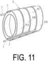
- a plurality of independent annular air chambers 6 (6A, 6B, 6C, and 6D) are arranged side by side, and the cushioning portion 5 is formed in a cylindrical body.
- the load B is inserted into each annular air chamber 6 (in a state where air is slightly injected), and then this cushioning portion 5 is stored inside the outer container 2. Thereafter, air is injected into each air chamber 6 to expand the cushioning portion 5, and the load B is held in a predetermined range inside the outer container 2.
- the cushioning portion 5 has a plurality of independent air chambers 6 (6A and 6B).
- Each of the air chambers 6 has a columnar shape, and these columnar air chambers 6 are arranged side by side in a spiral shape, and the cushioning portion 5 is formed in a cylindrical body.
- the cushioning portion 5 is integrated with the outer container 2 and disposed inside the outer container 2.
- the load B is held inside the cushioning portion 5 in the cylindrical body.
- the number of air chambers 6 is determined as appropriate. According to this embodiment, even when one air chamber 6 is damaged, the cushioning effect can be obtained by the remaining healthy air chamber 6.
- this cushioning portion 5 may also be separated from the outer container 2 so that the cushioning portion 5 can be put into and taken out of the outer container 2.
- a plurality of independent columnar air chambers 6 (6A and 6B) are arranged side by side in a spiral shape, and the cushioning portion 5 is formed in a cylindrical body.
- FIG. 14A illustrates a state in which two spiral air chambers 6A and 6B are combined side by side
- FIG. 14B illustrates a state in which the air chambers 6A and 6B are separated.
- the load B is inserted into each spiral air chamber 6 (in a state where air is slightly injected), and then this cushioning portion 5 is stored inside the outer container 2. Thereafter, air is injected into each air chamber 6 to expand the cushioning portion 5, and the load B is held in a predetermined range inside the outer container 2.
- the cushioning portion 5 includes a large number of linear members 5b formed of elastic members protruding from the inner surface side of the outer container 2 and is formed in a cylindrical body. These linear members 5b are disposed projecting on the surface of a base 5a having a flat plate shape. Inside the cushioning portion 5 in the cylindrical body, the load B is held in a state of being supported by a large number of elastic linear members 5b. For the specification of the linear members 5b (length, thickness, distribution density, and the like), a test or simulation of the cushioning effect of the cushioning portion 5 is performed in advance to determine the appropriate specification.
- the cushioning portion 5 is integrated with the outer container 2 and disposed inside the outer container 2. Accordingly, when the load B is disposed inside the cushioning portion 5 having the cylindrical body, the load B is held within a predetermined range inside the outer container 2. Thereafter, the load opening 3 is closed, and the operation of accommodating the load B in the delivery container 1 is completed.
- this cushioning portion 5 may also be separated from the outer container 2 so that the cushioning portion 5 can be put into and taken out of the outer container 2.
- this cushioning portion 5 a large number of linear members 5b formed of an elastic material projecting from one surface of the base 5a having a flat plate shape. The cushioning portion 5 wraps the load B and is formed into a cylindrical body and then is stored inside the outer container 2, so that the load B is held within a predetermined range inside the outer container 2.
- the outer container 2 may be formed in a simple spherical shape or an elliptical spherical shape such as a rugby ball to have a shape having a streamlined surface.
- the outer container 2 preferably has a shape having as few corners as possible, and even in a case of a cylindrical shape, the corners preferably have an arc shape (round shape).
- a large number of dimples 4 may be scattered on the outer surface of the outer container 2 like a golf ball. These dimples 4 make the flow of air around the outer surface of the outer container 2 appropriately turbulent during delivery. Along with this, the air resistance received by the outer container 2 is reduced, and an additional load acting on the drone D during delivery can be reduced.
- an air resistance test or simulation of the outer container 2 is performed in advance to determine the appropriate specification.
Landscapes
- Engineering & Computer Science (AREA)
- Mechanical Engineering (AREA)
- Aviation & Aerospace Engineering (AREA)
- Buffer Packaging (AREA)
Abstract
Description
- The present invention relates to a delivery container for a drone and more particularly relates to a delivery container for a drone that can prevent a load to be delivered from getting damaged or wet and can easily and more reliably protect the load.
- In recent years, so-called drones that use air routes have been attracting attention as a means of delivering loads. By using drones, relatively small (light weight) loads can be rapidly delivered to locations where delivery using land routes and water routes is difficult. When delivering a load using a drone, if a cushioning material and the load are packed and delivered together in corrugated cardboard, the load may be damaged by impact from the corrugated cardboard falling. Further, corrugated cardboard cannot sufficiently prevent the load stored therein from getting wet during delivery in rainy weather.
- Thus, a package using an outer container such as corrugated cardboard and an inner packaging material has been proposed (see Patent Document 1). In the package proposed in
Patent Document 1, the inner packaging material storing the load is held in a suspended state inside the outer container by a plurality of elastic towing ropes. Then, the inner packaging material storing the load is closed and the inside thereof is evacuated. Even if the load is held in a suspended state inside the outer container, when the outer container falls and is greatly deformed or damaged, the impact force also acts on the load, and so the load cannot be sufficiently protected. In addition, suspending the load in this way takes a lot of time and effort. Further, even if the inside of the inner packaging material can be evacuated to protect the load from moisture, it takes time and effort to evacuate the inside. Thus, there is room for improvement in more easily and reliably protecting the load. - Patent Document 1:
JP 2019-535603 T - An object of the present invention is to provide a delivery container for a drone that can prevent a load to be delivered from getting damaged or wet and can easily and more reliably protect the load.
- To achieve the object described above, a delivery container for a drone according to the present invention is a delivery container for a drone including an outer container held by a drone and a cushioning portion stored inside the outer container. The outer container is formed of an elastic material and is watertight, and a load opening of the outer container that opens and closes is designed to be watertight. The cushioning portion is interposed between a load stored inside the outer container and the outer container to hold the load within a predetermined range inside the outer container.
- According to the present invention, the load is protected from the impact force by a cushioning effect of the outer container formed of an elastic material and a cushioning effect of the cushioning portion stored inside the outer container. Further, since the outer container is watertight and the load opening is also designed to be watertight, it is possible to prevent the load from getting wet even during delivery in rainy weather. Even with this simple configuration, it is possible to more reliably protect the load.
-
-
FIG. 1 is an explanatory diagram illustrating an embodiment of a delivery container for a drone in a side view. -
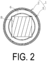
FIG. 2 is an explanatory diagram illustrating the delivery container ofFIG. 1 in a cross-sectional view. -
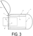
FIG. 3 is an explanatory diagram illustrating a state in which a load opening ofFIG. 1 is open. -
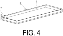
FIG. 4 is an explanatory diagram illustrating a modified example of a cushioning portion ofFIG. 1 . -
FIG. 5 is an explanatory diagram illustrating a state in which the load stored in the delivery container ofFIG. 1 is delivered by a drone. -
FIG. 6 is an explanatory diagram illustrating another embodiment of the delivery container in a side view. -
FIG. 7 is an explanatory diagram illustrating the delivery container ofFIG. 6 in a cross-sectional view. -
FIG. 8 is an explanatory diagram illustrating a modified example of the cushioning portion ofFIG. 6 . -
FIG. 9 is an explanatory diagram illustrating another embodiment of the delivery container in a side view. -
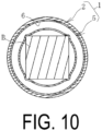
FIG. 10 is an explanatory diagram illustrating the delivery container ofFIG. 9 in a cross-sectional view. -
FIG. 11 is an explanatory diagram illustrating a modified example of the cushioning portion ofFIG. 9 . -
FIG. 12 is an explanatory diagram illustrating another embodiment of the delivery container in a side view. -
FIG. 13 is an explanatory diagram illustrating the delivery container ofFIG. 12 in a cross-sectional view. -
FIG. 14 illustrates a modified example of the cushioning portion ofFIG. 12 .FIG. 14(A) is an explanatory diagram illustrating a state in which two independent air chambers are combined.FIG. 14(B) is an explanatory diagram illustrating each air chamber independently. -
FIG. 15 is an explanatory diagram illustrating another embodiment of the delivery container in a side view. -
FIG. 16 is an explanatory diagram illustrating the delivery container ofFIG. 15 in a cross-sectional view. -
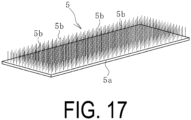
FIG. 17 is an explanatory diagram illustrating a modified example of the cushioning portion ofFIG. 15 . -
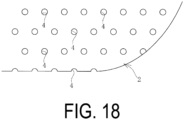
FIG. 18 is an enlarged view illustrating a modified example of the outer surface of the outer container. - A delivery container for a drone according to embodiments of the present invention will be described below with reference to the drawing.
- A delivery container for a
drone 1 according to an embodiment illustrated inFIGS. 1 to 3 includes anouter container 2 and acushioning portion 5 stored inside theouter container 2. Theouter container 2 is held by a drone D. Theouter container 2 is formed of an elastic material and is watertight. Examples of the elastic material forming theouter container 2 include various vulcanized rubbers, soft resins, and elastomer, and the like. Theouter container 2 may be formed of only an elastic material, or may be formed of an elastic material in which a reinforcing wire such as a fiber is embedded. An elastic material having a large number of gas bubbles may also be used for theouter container 2. - Various shapes may be employed for the
outer container 2. In this embodiment, theouter container 2 having a cylindrical shape is used. The wall thickness of theouter container 2 is, for example, approximately several mm or more and several cm or less. - The
outer container 2 is provided with a load opening 3 for taking a load B to be delivered in and out of theouter container 2. The load opening 3 that opens and closes is designed to be watertight. In this embodiment, theload opening 3 is provided at one end side of the shaft of the cylindricalouter container 2. - As a water stop portion 3a, the
load opening 3 includes a fastener that is watertight and extends along substantially the entire circumference in the circumferential direction of theouter container 2 having a cylindrical shape, and theload opening 3 is opened and closed by the fastener. In addition to fasteners that engage a pair of pieces, various known fasteners such as surface fasteners can be designed to be watertight and used as the water stop portion 3a. - The
cushioning portion 5 is interposed between the load B stored inside theouter container 2 and theouter container 2. Because thecushioning portion 5 is deformed (elastic deformation), the load B is held within a predetermined range inside theouter container 2. The predetermined range is a range in which the load B does not come into direct contact with theouter container 2. Because thecushioning portion 5 is deformed, the load B is held while displacement with respect to thecushioning portion 5 is suppressed. Further, since thecushioning portion 5 is pressed against the inner surface of theouter container 2, thecushioning portion 5 is in a state of being held while displacement with respect to theouter container 2 is suppressed. Since theouter container 2 is pressed from the inside by thecushioning portion 5, theouter container 2 is moderately strained to maintain a predetermined external shape. - The
cushioning portion 5 may be formed of a non-elastic material. However, in order to obtain a more excellent cushioning effect, it is preferably formed of an elastic material. Examples of the elastic material forming thecushioning portion 5 include various vulcanized rubbers, soft resins, and elastomer, and the like. Thecushioning portion 5 may be formed of only an elastic material, or may be formed of an elastic material in which a reinforcing wire such as a fiber is embedded. An elastic material having a large number of gas bubbles may also be used for thecushioning portion 5. - The
cushioning portion 5 preferably includes anair chamber 6 that is sealed in order to obtain a more excellent cushioning effect. When thecushioning portion 5 includes theair chamber 6, thecushioning portion 5 may also be formed of a non-elastic material. - The
cushioning portion 5 is preferably disposed so as to cover the entire outer circumference of the load B. When a partial range of the baggage B is made into an uncovered state by thecushioning portion 5, a certain distance (for example, 5 cm or more) is ensured between the partial range in the uncovered state and the inner surface of theouter container 2. - In this embodiment, the
cushioning portion 5 having a cylindrical body along the inner circumferential surface of theouter container 2 is included. Theair chamber 6 having a cylindrical shape is formed inside thecushioning portion 5. Anair injection inlet 7 is provided at an end portion of thecushioning portion 5 at theload opening 3 side. Air can be injected into and discharged from theair chamber 6 through theair injection inlet 7. By adjusting the amount of air injected into theair chamber 6, thecushioning portion 5 is expanded appropriately. - In this embodiment, the
cushioning portion 5 is integrated with theouter container 2 and disposed inside theouter container 2. Accordingly, before air is injected into theair chamber 6 to expand thecushioning portion 5, the load B is disposed inside thecylindrical cushioning portion 5, and then air is injected into theair chamber 6 and thecushioning portion 5 is expanded. In this way, the load B is held in the predetermined range inside theouter container 2. Thereafter, theload opening 3 is closed, and the operation of accommodating the load B in thedelivery container 1 is completed. - As illustrated in
FIG. 4 , thecushioning portion 5 may be separated from theouter container 2 so that thecushioning portion 5 can be put into and taken out of theouter container 2. In thecushioning portion 5, theair chamber 6 is formed inside thecushioning portion 5 having a flat plate shape. This flat plate-shapedcushioning portion 5 wraps the load B and is formed into a cylindrical body, and then is stored inside theouter container 2. Thereafter, air is injected into theair chamber 6 to expand thecushioning portion 5, and the load B is held in a predetermined range inside theouter container 2. - The
delivery container 1 is used as follows when delivering the load B. - As illustrated in
FIG. 5 , thedelivery container 1 in which the load B is stored is held in a holding arm Da of the drone D flying by remote control or automatic control, and is delivered by air from the delivery source to the destination. When thedelivery container 1 arrives at the destination, the holding by the holding arm Da is released, thedelivery container 1 is separated from the drone D, and the delivery is completed. - Even when the
delivery container 1 falls from an unintended height when the holding by the holding arm Da is released or during delivery, in thedelivery container 1, theouter container 2 formed of an elastic material and thecushioning portion 5 exhibit the cushioning function. That is, by the cushioning effect of theouter container 2 and the cushioning effect of thecushioning portion 5, the load B is protected from the impact force generated when dropped. When thecushioning portion 5 formed of an elastic material or thecushioning portion 5 having theair chamber 6 is used, the cushioning effect is further improved, which is more advantageous for protecting the load B from the impact force. - Since the
outer container 2 is watertight and theload opening 3 is also designed to be watertight, moisture is prevented from entering the inside of theouter container 2. Thus, even in a case of delivery in rainy weather or the like, the use of thisdelivery container 1 prevents the load B from getting wet. As described above, while thedelivery container 1 has a simple configuration, it is possible to more reliably protect the load B. - When the load B is displaced inside the
outer container 2 during delivery, the balance of the drone D is lost and the flight becomes unstable. However, in thisdelivery container 1, the load B is held in a state where displacement with respect to thecushioning portion 5 is suppressed, and thecushioning portion 5 is held in a state where displacement with respect to theouter container 2 is suppressed. Thus, the displacement of the load B is unlikely to occur inside theouter container 2 during delivery, which is advantageous for the stable flight of the drone D. Further, since theouter container 2 is pressed from the inside by thecushioning portion 5 to maintain a predetermined external shape, the external shape of theouter container 2 does not easily change during delivery. From this perspective, it is advantageous for the stable flight of the drone D. - When the
cushioning portion 5 has oneair chamber 6, the cushioning effect of thecushioning portion 5 is reduced when theair chamber 6 is damaged. Thus, it is preferable that thecushioning portion 5 includes a plurality ofindependent air chambers 6. - In the embodiment of the
delivery container 1 illustrated inFIGS. 6 to 7 , thecushioning portion 5 has a plurality of independent air chambers 6 (6A, 6B, 6C, 6D, 6E, 6F, 6G, and 6H). Each of theair chambers 6 has a columnar shape, and thesecolumnar air chambers 6 are arranged side by side in a cylindrical shape, and thecushioning portion 5 is formed in a cylindrical body. Thecushioning portion 5 is integrated with theouter container 2 and disposed inside theouter container 2. The load B is held inside thecushioning portion 5 in the cylindrical body. The number ofair chambers 6 is determined as appropriate. According to this embodiment, even when oneair chamber 6 is damaged, the cushioning effect can be obtained by the remaininghealthy air chamber 6. - As illustrated in
FIG. 8 , thiscushioning portion 5 may also be separated from theouter container 2 so that thecushioning portion 5 can be put into and taken out of theouter container 2. In thiscushioning portion 5, a plurality of columnar independent air chambers 6 (6A, 6B, 6C, 6D, 6E, 6F, 6G, and 6H) are formed side by side inside thecushioning portion 5 having a flat plate shape. Thiscushioning portion 5 wraps the load B and is formed into a cylindrical body, and then is stored inside theouter container 2. Thereafter, air is injected into eachair chamber 6 to expand thecushioning portion 5, and the load B is held in a predetermined range inside theouter container 2. - In the embodiment of the
delivery container 1 illustrated inFIGS. 9 to 10 , thecushioning portion 5 has a plurality of independent air chambers 6 (6A, 6B, 6C, and 6D). Each of theair chambers 6 is annular, and theseannular air chambers 6 are arranged side by side in the width direction, and thecushioning portion 5 is formed in a cylindrical body. Thecushioning portion 5 is integrated with theouter container 2 and disposed inside theouter container 2. The load B is held inside thecushioning portion 5 in the cylindrical body. The number ofair chambers 6 is determined as appropriate. According to this embodiment, even when oneair chamber 6 is damaged, the cushioning effect can be obtained by the remaininghealthy air chamber 6. - As illustrated in
FIG. 11 , thiscushioning portion 5 may also be separated from theouter container 2 so that thecushioning portion 5 can be put into and taken out of theouter container 2. A plurality of independent annular air chambers 6 (6A, 6B, 6C, and 6D) are arranged side by side, and thecushioning portion 5 is formed in a cylindrical body. The load B is inserted into each annular air chamber 6 (in a state where air is slightly injected), and then thiscushioning portion 5 is stored inside theouter container 2. Thereafter, air is injected into eachair chamber 6 to expand thecushioning portion 5, and the load B is held in a predetermined range inside theouter container 2. - In the embodiment of the
delivery container 1 illustrated inFIGS. 12 to 13 , thecushioning portion 5 has a plurality of independent air chambers 6 (6A and 6B). Each of theair chambers 6 has a columnar shape, and thesecolumnar air chambers 6 are arranged side by side in a spiral shape, and thecushioning portion 5 is formed in a cylindrical body. Thecushioning portion 5 is integrated with theouter container 2 and disposed inside theouter container 2. The load B is held inside thecushioning portion 5 in the cylindrical body. The number ofair chambers 6 is determined as appropriate. According to this embodiment, even when oneair chamber 6 is damaged, the cushioning effect can be obtained by the remaininghealthy air chamber 6. - As illustrated in
FIG. 14 , thiscushioning portion 5 may also be separated from theouter container 2 so that thecushioning portion 5 can be put into and taken out of theouter container 2. A plurality of independent columnar air chambers 6 (6A and 6B) are arranged side by side in a spiral shape, and thecushioning portion 5 is formed in a cylindrical body.FIG. 14A illustrates a state in which twospiral air chambers FIG. 14B illustrates a state in which theair chambers cushioning portion 5 is stored inside theouter container 2. Thereafter, air is injected into eachair chamber 6 to expand thecushioning portion 5, and the load B is held in a predetermined range inside theouter container 2. - In the embodiment of the
delivery container 1 illustrated inFIGS. 15 to 16 , thecushioning portion 5 includes a large number oflinear members 5b formed of elastic members protruding from the inner surface side of theouter container 2 and is formed in a cylindrical body. Theselinear members 5b are disposed projecting on the surface of abase 5a having a flat plate shape. Inside thecushioning portion 5 in the cylindrical body, the load B is held in a state of being supported by a large number of elasticlinear members 5b. For the specification of thelinear members 5b (length, thickness, distribution density, and the like), a test or simulation of the cushioning effect of thecushioning portion 5 is performed in advance to determine the appropriate specification. - In this embodiment, the
cushioning portion 5 is integrated with theouter container 2 and disposed inside theouter container 2. Accordingly, when the load B is disposed inside thecushioning portion 5 having the cylindrical body, the load B is held within a predetermined range inside theouter container 2. Thereafter, theload opening 3 is closed, and the operation of accommodating the load B in thedelivery container 1 is completed. - As illustrated in
FIG. 17 , thiscushioning portion 5 may also be separated from theouter container 2 so that thecushioning portion 5 can be put into and taken out of theouter container 2. In thiscushioning portion 5, a large number oflinear members 5b formed of an elastic material projecting from one surface of thebase 5a having a flat plate shape. Thecushioning portion 5 wraps the load B and is formed into a cylindrical body and then is stored inside theouter container 2, so that the load B is held within a predetermined range inside theouter container 2. - Various shapes can be employed for the
outer container 2, but in order to reduce the air resistance received during delivery, for example, theouter container 2 may be formed in a simple spherical shape or an elliptical spherical shape such as a rugby ball to have a shape having a streamlined surface. Further, theouter container 2 preferably has a shape having as few corners as possible, and even in a case of a cylindrical shape, the corners preferably have an arc shape (round shape). - As illustrated in
FIG. 18 , a large number ofdimples 4 may be scattered on the outer surface of theouter container 2 like a golf ball. Thesedimples 4 make the flow of air around the outer surface of theouter container 2 appropriately turbulent during delivery. Along with this, the air resistance received by theouter container 2 is reduced, and an additional load acting on the drone D during delivery can be reduced. For the specification of the dimple 4 (size, shape, distribution density, and the like), an air resistance test or simulation of theouter container 2 is performed in advance to determine the appropriate specification. -
- 1 Delivery container
- 2 Outer container
- 3 Load opening
- 3a Water stop portion
- 4 Dimple
- 5 Cushioning portion
- 5a Base
- 5b Linear member
- 6 (6A, 6B, 6C, 6D, 6E, 6F, 6G, 6H) Air chamber
- 7 Air injection inlet
- B Load
- D Drone
- Da Holding arm
Claims (11)
- A delivery container for a drone, comprising:an outer container held by a drone; anda cushioning portion stored inside the outer container,the outer container being formed of an elastic material and being watertight, and a load opening of the outer container that opens and closes being designed to be watertight, andthe cushioning portion being interposed between a load stored inside the outer container and the outer container to hold the load within a predetermined range inside the outer container.
- The delivery container for a drone according to claim 1, wherein the cushioning portion is integrated with the outer container and disposed inside the outer container.
- The delivery container for a drone according to claim 1, wherein the cushioning portion can be separated from the outer container and taken in and out of the outer container.
- The delivery container for a drone according to any one of claims 1 to 3, wherein the cushioning portion is formed of an elastic material.
- The delivery container for a drone according to any one of claims 1 to 4, wherein the cushioning portion comprises an air chamber that is sealed.
- The delivery container for a drone according to claim 5, wherein a plurality of the air chambers are provided with each being independent.
- The delivery container for a drone according to claim 6, wherein each of the air chambers has a columnar shape, and the air chambers each having the columnar shape are arranged side by side in a cylindrical shape and the cushioning portion is formed in a cylindrical body, and the load is held inside the cylindrical body.
- The delivery container for a drone according to claim 6, wherein each of the air chambers is annular, and the air chambers each being annular are arranged side by side in a width direction and the cushioning portion is formed in a cylindrical body, and the load is held inside the cylindrical body.
- The delivery container for a drone according to claim 6, wherein each of the air chambers has a columnar shape, and the air chambers each having the columnar shape are arranged side by side in a spiral shape and the cushioning portion is formed in a cylindrical body, and the load is held inside the cylindrical body.
- The delivery container for a drone according to claim 4, wherein the cushioning portion comprises a large number of linear members protruding from an inner surface side of the outer container.
- The delivery container for a drone according to any one of claims 1 to 10, wherein a large number of dimples are scattered on an outer surface of the outer container.
Applications Claiming Priority (2)
| Application Number | Priority Date | Filing Date | Title |
|---|---|---|---|
| JP2020061860A JP7372547B2 (en) | 2020-03-31 | 2020-03-31 | Drone shipping container |
| PCT/JP2020/042706 WO2021199486A1 (en) | 2020-03-31 | 2020-11-17 | Drone transport container |
Publications (2)
| Publication Number | Publication Date |
|---|---|
| EP4129855A1 true EP4129855A1 (en) | 2023-02-08 |
| EP4129855A4 EP4129855A4 (en) | 2024-05-01 |
Family
ID=77928392
Family Applications (1)
| Application Number | Title | Priority Date | Filing Date |
|---|---|---|---|
| EP20929034.5A Pending EP4129855A4 (en) | 2020-03-31 | 2020-11-17 | DRONE TRANSPORT CONTAINER |
Country Status (5)
| Country | Link |
|---|---|
| US (1) | US12157620B2 (en) |
| EP (1) | EP4129855A4 (en) |
| JP (1) | JP7372547B2 (en) |
| AU (1) | AU2020439140B2 (en) |
| WO (1) | WO2021199486A1 (en) |
Families Citing this family (1)
| Publication number | Priority date | Publication date | Assignee | Title |
|---|---|---|---|---|
| JP7340141B1 (en) | 2023-03-17 | 2023-09-07 | ライセン株式会社 | Transport box for unmanned aerial vehicle |
Family Cites Families (35)
| Publication number | Priority date | Publication date | Assignee | Title |
|---|---|---|---|---|
| JPS5118881U (en) * | 1974-07-27 | 1976-02-12 | ||
| FR2385606A1 (en) * | 1977-03-29 | 1978-10-27 | Asnieres Prony Ste Civile Immo | Shockproof packing for fragile object - has inflatable bag formed of connected envelopes with inflation valve located adjacent box opening |
| US4164970A (en) | 1977-05-25 | 1979-08-21 | Jordan Charles P | Inflatable bag |
| JPS60193075U (en) * | 1984-05-30 | 1985-12-21 | 高山産業株式会社 | elastic protection material |
| JPH0453676U (en) * | 1990-09-07 | 1992-05-07 | ||
| JPH086216B2 (en) * | 1992-04-14 | 1996-01-24 | 森川撚糸株式会社 | Surface structure of textile machine structural parts |
| JPH1047315A (en) * | 1996-07-29 | 1998-02-17 | Junichi Hirata | Fluid resistance reducing apparatus |
| AT406667B (en) | 1997-05-14 | 2000-07-25 | Oswald Wolfgang Ing | PACKAGING AND METHOD FOR PRODUCING THE SAME |
| JP3050126U (en) * | 1997-12-24 | 1998-06-30 | モリト株式会社 | Antibacterial cool box |
| KR20010000922A (en) * | 2000-10-24 | 2001-01-05 | 오상일 | An egg holding sheet in a packing case |
| JP2006321511A (en) | 2005-05-17 | 2006-11-30 | Max Co Ltd | Transfer container |
| GB0600121D0 (en) * | 2006-01-05 | 2006-02-15 | Fruity Faces Ltd | Inflatable friut/food carrier/case |
| JP5373506B2 (en) * | 2009-08-20 | 2013-12-18 | 親和パッケージ株式会社 | Helical cushioning member |
| FR2970631B1 (en) * | 2011-01-20 | 2014-01-31 | Alexandre Stourdza | TABLE FEET PROTECTIVE DEVICE |
| JP2013193567A (en) * | 2012-03-19 | 2013-09-30 | Tatsuya Yamashita | Sheet-like spoiler with dimple for improvement in aerodynamic force of wagon, bus, truck, container or the like |
| US9440749B1 (en) * | 2015-03-05 | 2016-09-13 | Comac America Corporation | Emergency mechanical and communication systems and methods for aircraft |
| US10137986B1 (en) * | 2015-03-25 | 2018-11-27 | Amazon Technologies, Inc. | Airlift package protection airbag container |
| US9914539B1 (en) | 2015-03-25 | 2018-03-13 | Amazon Technologies, Inc. | Airlift package protection airbag |
| US10745130B2 (en) | 2015-07-28 | 2020-08-18 | The Skylife Company, Inc. | Container for aerial delivery |
| US9663234B1 (en) * | 2015-08-26 | 2017-05-30 | Amazon Technologies, Inc. | Aerial package delivery system |
| US20170267348A1 (en) * | 2015-10-14 | 2017-09-21 | Flirtey Holdings, Inc. | Packaging container for drone delivery |
| US10618655B2 (en) * | 2015-10-14 | 2020-04-14 | Flirtey Holdings, Inc. | Package delivery mechanism in an unmanned aerial vehicle |
| US10336453B2 (en) | 2016-01-14 | 2019-07-02 | Elwha Llc | System and method for payload management for unmanned aircraft |
| US10131428B1 (en) | 2016-02-18 | 2018-11-20 | Wing Aviation Llc | Inflatable packaging for use with UAV |
| KR101653764B1 (en) | 2016-03-22 | 2016-09-02 | 주식회사 에프엠에스코리아 | Box package for drone |
| DE102016117611B4 (en) * | 2016-09-19 | 2020-03-05 | Airrobot Gmbh & Co. Kg | Device for the air transport of an object |
| DE102016012963A1 (en) | 2016-11-01 | 2018-05-03 | Armin König | Packaging process and transport packaging |
| US10410105B1 (en) * | 2016-11-11 | 2019-09-10 | Ingar LLC | Containers for aerial drone transport of materials, objects, or products |
| JP2018118753A (en) * | 2017-01-24 | 2018-08-02 | 治生 藤本 | Minus weight cushioning material |
| CN207090079U (en) | 2017-06-02 | 2018-03-13 | 于天骐 | A kind of encapsulated packaging structure |
| US20190066032A1 (en) * | 2017-08-22 | 2019-02-28 | Qualcomm Incorporated | Robotic Vehicle Item Delivery Security System |
| CN109552757A (en) * | 2017-09-26 | 2019-04-02 | 田珉 | Express delivery turnover box with inflatable bladder |
| US10737782B2 (en) * | 2017-09-29 | 2020-08-11 | Intel Corporation | Drone based delivery system |
| FR3075170B1 (en) * | 2017-12-20 | 2020-02-14 | Airbus Helicopters | LOAD CARRYING SYSTEM FOR DRONE DRONE |
| US11414186B2 (en) * | 2018-03-20 | 2022-08-16 | Arin O'Donnell | Unmanned aerial vehicle with a container having a stabilizing system |
-
2020
- 2020-03-31 JP JP2020061860A patent/JP7372547B2/en active Active
- 2020-11-17 WO PCT/JP2020/042706 patent/WO2021199486A1/en not_active Ceased
- 2020-11-17 AU AU2020439140A patent/AU2020439140B2/en active Active
- 2020-11-17 US US17/797,248 patent/US12157620B2/en active Active
- 2020-11-17 EP EP20929034.5A patent/EP4129855A4/en active Pending
Also Published As
| Publication number | Publication date |
|---|---|
| EP4129855A4 (en) | 2024-05-01 |
| JP2021160731A (en) | 2021-10-11 |
| AU2020439140B2 (en) | 2024-08-15 |
| US20230066388A1 (en) | 2023-03-02 |
| JP7372547B2 (en) | 2023-11-01 |
| US12157620B2 (en) | 2024-12-03 |
| AU2020439140A1 (en) | 2022-07-14 |
| WO2021199486A1 (en) | 2021-10-07 |
Similar Documents
| Publication | Publication Date | Title |
|---|---|---|
| US11592271B2 (en) | Foam dart having a safety cap | |
| ES2774042T3 (en) | Deployable air rescue package | |
| KR102010863B1 (en) | Parachute apparatus for drone | |
| US12157620B2 (en) | Delivery container for drone | |
| US20100084396A1 (en) | Airtight container | |
| US20250221390A1 (en) | Insect release devices | |
| JPWO2017154551A1 (en) | Flying object | |
| US20120248110A1 (en) | Airtight container | |
| CA2422421C (en) | Airdrop type buoy apparatus | |
| JP2016088417A (en) | Impact absorption bag and impact absorption apparatus | |
| ES2453272T3 (en) | Aerodynamic Frisbee | |
| RU2678382C1 (en) | Coaxial double layer parachute | |
| ES2346817T3 (en) | AIR PUMP PENETRATION PROVIDED WITH AN EXTERNAL COATING. | |
| US2770666A (en) | Storage battery with vent plug | |
| US11803194B2 (en) | Monolithic attitude control motor frame and system | |
| US2423940A (en) | Expansible impact container provided with yieldable retaining means | |
| US20150323088A1 (en) | Magnetic Breather Valve | |
| CN110379283B (en) | Large-volume split-type water rocket parachute chamber and water rocket | |
| US11851155B1 (en) | Small zero pressure balloon systems | |
| RU235573U1 (en) | Capsule for transportation | |
| US2415818A (en) | Balloon with parachute | |
| CN109631668A (en) | A kind of self-balancing bullet separation pressure difference bullet support component and application method | |
| US10464730B2 (en) | Piston box | |
| JP7473266B1 (en) | Container for projectiles and projectiles | |
| CN213974496U (en) | Umbrella cover of drag umbrella |
Legal Events
| Date | Code | Title | Description |
|---|---|---|---|
| STAA | Information on the status of an ep patent application or granted ep patent |
Free format text: STATUS: THE INTERNATIONAL PUBLICATION HAS BEEN MADE |
|
| PUAI | Public reference made under article 153(3) epc to a published international application that has entered the european phase |
Free format text: ORIGINAL CODE: 0009012 |
|
| STAA | Information on the status of an ep patent application or granted ep patent |
Free format text: STATUS: REQUEST FOR EXAMINATION WAS MADE |
|
| 17P | Request for examination filed |
Effective date: 20221019 |
|
| AK | Designated contracting states |
Kind code of ref document: A1 Designated state(s): AL AT BE BG CH CY CZ DE DK EE ES FI FR GB GR HR HU IE IS IT LI LT LU LV MC MK MT NL NO PL PT RO RS SE SI SK SM TR |
|
| DAV | Request for validation of the european patent (deleted) | ||
| DAX | Request for extension of the european patent (deleted) | ||
| RAP3 | Party data changed (applicant data changed or rights of an application transferred) |
Owner name: THE YOKOHAMA RUBBER CO., LTD. |
|
| A4 | Supplementary search report drawn up and despatched |
Effective date: 20240405 |
|
| RIC1 | Information provided on ipc code assigned before grant |
Ipc: B64D 1/14 20060101ALI20240328BHEP Ipc: B64D 9/00 20060101ALI20240328BHEP Ipc: B64C 39/02 20060101ALI20240328BHEP Ipc: B65D 81/05 20060101AFI20240328BHEP |
|
| RAP3 | Party data changed (applicant data changed or rights of an application transferred) |
Owner name: THE YOKOHAMA RUBBER CO., LTD. |
|
| STAA | Information on the status of an ep patent application or granted ep patent |
Free format text: STATUS: EXAMINATION IS IN PROGRESS |
|
| 17Q | First examination report despatched |
Effective date: 20250711 |