EP4129836A1 - Extensible habitat pressure control for planetary and orbital space vehicles - Google Patents
Extensible habitat pressure control for planetary and orbital space vehicles Download PDFInfo
- Publication number
- EP4129836A1 EP4129836A1 EP22187323.5A EP22187323A EP4129836A1 EP 4129836 A1 EP4129836 A1 EP 4129836A1 EP 22187323 A EP22187323 A EP 22187323A EP 4129836 A1 EP4129836 A1 EP 4129836A1
- Authority
- EP
- European Patent Office
- Prior art keywords
- oxygen
- pressure
- nitrogen
- module
- control board
- Prior art date
- Legal status (The legal status is an assumption and is not a legal conclusion. Google has not performed a legal analysis and makes no representation as to the accuracy of the status listed.)
- Granted
Links
Images
Classifications
-
- B—PERFORMING OPERATIONS; TRANSPORTING
- B64—AIRCRAFT; AVIATION; COSMONAUTICS
- B64G—COSMONAUTICS; VEHICLES OR EQUIPMENT THEREFOR
- B64G1/00—Cosmonautic vehicles
- B64G1/22—Parts of, or equipment specially adapted for fitting in or to, cosmonautic vehicles
- B64G1/46—Arrangements or adaptations of devices for control of environment or living conditions
- B64G1/48—Arrangements or adaptations of devices for control of environment or living conditions for treatment of the atmosphere
-
- B—PERFORMING OPERATIONS; TRANSPORTING
- B64—AIRCRAFT; AVIATION; COSMONAUTICS
- B64G—COSMONAUTICS; VEHICLES OR EQUIPMENT THEREFOR
- B64G1/00—Cosmonautic vehicles
- B64G1/22—Parts of, or equipment specially adapted for fitting in or to, cosmonautic vehicles
- B64G1/60—Crew or passenger accommodations
-
- G—PHYSICS
- G05—CONTROLLING; REGULATING
- G05D—SYSTEMS FOR CONTROLLING OR REGULATING NON-ELECTRIC VARIABLES
- G05D16/00—Control of fluid pressure
- G05D16/20—Control of fluid pressure characterised by the use of electric means
- G05D16/2006—Control of fluid pressure characterised by the use of electric means with direct action of electric energy on controlling means
- G05D16/2013—Control of fluid pressure characterised by the use of electric means with direct action of electric energy on controlling means using throttling means as controlling means
- G05D16/2026—Control of fluid pressure characterised by the use of electric means with direct action of electric energy on controlling means using throttling means as controlling means with a plurality of throttling means
- G05D16/204—Control of fluid pressure characterised by the use of electric means with direct action of electric energy on controlling means using throttling means as controlling means with a plurality of throttling means the plurality of throttling means being arranged in parallel
-
- B—PERFORMING OPERATIONS; TRANSPORTING
- B64—AIRCRAFT; AVIATION; COSMONAUTICS
- B64D—EQUIPMENT FOR FITTING IN OR TO AIRCRAFT; FLIGHT SUITS; PARACHUTES; ARRANGEMENT OR MOUNTING OF POWER PLANTS OR PROPULSION TRANSMISSIONS IN AIRCRAFT
- B64D13/00—Arrangements or adaptations of air-treatment apparatus for aircraft crew or passengers, or freight space
- B64D13/06—Arrangements or adaptations of air-treatment apparatus for aircraft crew or passengers, or freight space the air being conditioned
- B64D2013/0603—Environmental Control Systems
- B64D2013/0681—Environmental Control Systems with oxygen control
Definitions
- the present disclosure relates generally to planetary and orbital space vehicles and, more particularly, to habitat or environmental control systems that may be scaled to specific requirements of planetary and orbital space vehicles, as well as related equipment, such as pressurized garments and the like used outside of planetary and orbital space vehicles.
- the first oxygen control board includes an oxygen pressure transducer configured to determine an oxygen pressure within the first oxygen control board.
- the first oxygen control board includes an oxygen solenoid valve configured to regulate and to release the oxygen gas into the first module.
- the low-pressure oxygen gas and the low-pressure nitrogen gas are then delivered to a pressure control panel 212, similar to the first pressure control panel 112 and the second pressure control panel 114 described above with reference to FIG. 1 , which is configured to control the partial pressure of oxygen and the partial pressure of nitrogen within a module or compartment, such as, for example, the first module 102 or the second module 104 described above with reference to FIG. 1 .
- the manual shutoff valve 234 is configured to shutoff the supply of oxygen gas from the oxygen supply 206.
- a pressure regulator is a system or device configured to reduce pressure of a gas from a high-pressure value to a low-pressure value, with the low-pressure value being less than the high-pressure value.
Landscapes
- Engineering & Computer Science (AREA)
- Remote Sensing (AREA)
- Aviation & Aerospace Engineering (AREA)
- Physics & Mathematics (AREA)
- Fluid Mechanics (AREA)
- General Health & Medical Sciences (AREA)
- Environmental & Geological Engineering (AREA)
- Environmental Sciences (AREA)
- Biodiversity & Conservation Biology (AREA)
- Toxicology (AREA)
- Life Sciences & Earth Sciences (AREA)
- Health & Medical Sciences (AREA)
- General Physics & Mathematics (AREA)
- Automation & Control Theory (AREA)
- Filling Or Discharging Of Gas Storage Vessels (AREA)
- Control Of Fluid Pressure (AREA)
Abstract
Description
- The present disclosure relates generally to planetary and orbital space vehicles and, more particularly, to habitat or environmental control systems that may be scaled to specific requirements of planetary and orbital space vehicles, as well as related equipment, such as pressurized garments and the like used outside of planetary and orbital space vehicles.
- Planetary and orbital space vehicles require an environment or habitat controlled and configured for breathing by the occupants of such vehicles. For example, the partial pressure levels of oxygen and nitrogen in the various compartments or modules of such vehicles may be controlled to emulate the levels typically found at sea level on Earth. Further, discreet compartments or modules within such vehicles - e.g., unoccupied compartments or modules - may require lower levels of oxygen or nitrogen depending on the intended use or nonuse of the compartment or module at any particular time. For example, the environment within an airlock chamber or a crew lock chamber typically requires a deviation from sea level conditions when an astronaut is preparing for a spacewalk. Localized pressure control panels positioned within discreet compartments or modules are beneficial in providing a localized and convenient means of controlling the partial pressure levels of oxygen and nitrogen and the ambient pressure within such discreet compartments or modules.
- An environmental control system for a space vehicle is disclosed. In various embodiments, the environmental control system includes an oxygen supply; a nitrogen supply; a first pressure control panel having a first oxygen control board configured to receive an oxygen gas from the oxygen supply and a first nitrogen control board configured to receive a nitrogen gas from the nitrogen supply; and a supervisory controller configured to control the first pressure control panel and thereby to adjust a partial pressure of oxygen and an ambient pressure of an oxygen/nitrogen gas mixture within a first module.
- In various embodiments, the environmental control system further includes an oxygen high-pressure regulator disposed between the oxygen supply and the first oxygen control board, the oxygen high-pressure regulator configured to reduce a high-pressure oxygen gas to a low-pressure oxygen gas. In various embodiments, the environmental control system further includes a nitrogen high-pressure regulator disposed between the nitrogen supply and the first nitrogen control board, the nitrogen high-pressure regulator configured to reduce a high-pressure nitrogen gas to a low-pressure nitrogen gas.
- In various embodiments, the first oxygen control board includes an oxygen pressure transducer configured to determine an oxygen pressure within the first oxygen control board. In various embodiments, the first oxygen control board includes an oxygen solenoid valve configured to regulate and to release the oxygen gas into the first module.
- In various embodiments, the first nitrogen control board includes a nitrogen pressure transducer configured to determine a nitrogen pressure within the first nitrogen control board. In various embodiments, the first nitrogen control board includes a nitrogen solenoid valve configured to regulate and to release the nitrogen gas into the first module.
- In various embodiments, the environmental control system further includes an oxygen sensor configured to measure the partial pressure of oxygen within the first module. In various embodiments, the first oxygen control board is configured to release the oxygen gas into the first module when the partial pressure of oxygen within the first module is below an oxygen pressure threshold value. In various embodiments, the first oxygen control board is configured to stop release of the oxygen gas into the first module when the partial pressure of oxygen within the first module is above the oxygen pressure threshold value.
- In various embodiments, the environmental control system further includes an ambient pressure sensor configured to measure the ambient pressure within the first module. In various embodiments, the first nitrogen control board is configured to release the nitrogen gas into the first module when the ambient pressure is below an ambient pressure threshold value and the partial pressure of oxygen within the first module is above the oxygen pressure threshold value. In various embodiments, the first nitrogen control board is configured to stop release of the nitrogen gas into the first module when the ambient pressure is above the ambient pressure threshold value and the partial pressure of oxygen within the first module is above the oxygen pressure threshold value. In various embodiments, the first pressure control panel includes a pressure relief solenoid valve configured to exhaust at least a portion of the oxygen/nitrogen gas mixture from the first module if the ambient pressure exceeds the ambient pressure threshold value.
- In various embodiments, the environmental control system further includes a second pressure control panel having a second oxygen control board configured to receive the oxygen gas from the oxygen supply and a second nitrogen control board configured to receive the nitrogen gas from the nitrogen supply. In various embodiments, the supervisory controller is configured to control the second pressure control panel and thereby to adjust the partial pressure of oxygen and the ambient pressure of the oxygen/nitrogen gas mixture within a second module. In various embodiments, the second pressure control panel can provide environmental control redundancy to the first pressure control panel when the modules are not isolated from one another.
- A space vehicle is disclosed. In various embodiments, the space vehicle includes a first module; a second module; an oxygen supply; a nitrogen supply; a first pressure control panel within the first module, the first pressure control panel having a first oxygen control board configured to receive an oxygen gas from the oxygen supply and a first nitrogen control board configured to receive a nitrogen gas from the nitrogen supply; a second pressure control panel within the second module, the second pressure control panel having a second oxygen control board configured to receive the oxygen gas from the oxygen supply and a second nitrogen control board configured to receive the nitrogen gas from the nitrogen supply; and a supervisory controller configured to control the first pressure control panel and thereby to adjust a first partial pressure of oxygen and a first ambient pressure of a first oxygen/nitrogen gas mixture within the first module and to control the second pressure control panel and thereby to adjust a second partial pressure of oxygen and a second ambient pressure of a second oxygen/nitrogen gas mixture within the second module.
- In various embodiments, the first oxygen control board includes an oxygen pressure transducer configured to determine an oxygen pressure within the first oxygen control board and an oxygen solenoid valve configured to regulate and to release the oxygen gas into the first module. In various embodiments, the first nitrogen control board includes a nitrogen pressure transducer configured to determine a nitrogen pressure within the first nitrogen control board and a nitrogen solenoid valve configured to regulate and to release the nitrogen gas into the first module.
- In various embodiments, the space vehicle further includes a first oxygen sensor configured to measure the first partial pressure of oxygen within the first module and the first oxygen control board is configured to release the oxygen gas into the first module when the first partial pressure of oxygen within the first module is below an oxygen pressure threshold value and to stop release of the oxygen gas into the first module when the first partial pressure of oxygen within the first module is above the oxygen pressure threshold value.
- In various embodiments, the space vehicle further includes an ambient pressure sensor configured to measure the first ambient pressure within the first module. In various embodiments, the first nitrogen control board is configured to release the nitrogen gas into the first module when the first ambient pressure is below an ambient pressure threshold value and the first partial pressure of oxygen within the first module is above the oxygen pressure threshold value. In various embodiments, the first nitrogen control board is configured to stop release of the nitrogen gas into the first module when the first ambient pressure is above the ambient pressure threshold value and the first partial pressure of oxygen within the first module is above the oxygen pressure threshold value. In various embodiments, the first pressure control panel includes a pressure relief solenoid valve configured to exhaust at least a portion of the first oxygen/nitrogen gas mixture from the first module if the first ambient pressure exceeds the ambient pressure threshold value.
- The foregoing features and elements may be combined in any combination, without exclusivity, unless expressly indicated herein otherwise. These features and elements as well as the operation of the disclosed embodiments will become more apparent in light of the following description and accompanying drawings.
- The subject matter of the present disclosure is particularly pointed out and distinctly claimed in the concluding portion of the specification. A more complete understanding of the present disclosure, however, may best be obtained by referring to the following detailed description and claims in connection with the following drawings. While the drawings illustrate various embodiments employing the principles described herein, the drawings do not limit the scope of the claims.
-
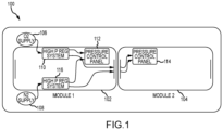
FIG. 1 provides a schematic view of a pair of modules having environmental control systems within a planetary or orbital space vehicle, in accordance with various embodiments; -
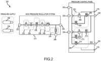
FIG. 2 provides a schematic view of an environmental control system for a planetary or orbital space vehicle, in accordance with various embodiments; and -
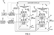
FIG. 3 provides a schematic view of an environmental control system for a planetary or orbital space vehicle, in accordance with various embodiments. - The following detailed description of various embodiments herein makes reference to the accompanying drawings, which show various embodiments by way of illustration. While these various embodiments are described in sufficient detail to enable those skilled in the art to practice the disclosure, it should be understood that other embodiments may be realized and that changes may be made without departing from the scope of the disclosure. Thus, the detailed description herein is presented for purposes of illustration only and not of limitation. Furthermore, any reference to singular includes plural embodiments, and any reference to more than one component or step may include a singular embodiment or step. Also, any reference to attached, fixed, connected, or the like may include permanent, removable, temporary, partial, full or any other possible attachment option. Additionally, any reference to without contact (or similar phrases) may also include reduced contact or minimal contact. It should also be understood that unless specifically stated otherwise, references to "a," "an" or "the" may include one or more than one and that reference to an item in the singular may also include the item in the plural. Further, all ranges may include upper and lower values and all ranges and ratio limits disclosed herein may be combined.
- Referring now to the drawings,
FIG. 1 schematically illustrates a space vehicle 100 (e.g., a planetary or orbital space vehicle) having afirst module 102 and asecond module 104. Thespace vehicle 100 includes anoxygen supply 106 and anitrogen supply 108, each of which may comprise a high-pressure tank or a gas generator configured to generate oxygen or nitrogen at high-pressure (e.g., on the order of about 500 psi (≈ 3,450 KPa) to about 4,000 psi (≈ 27,600KPa)). Theoxygen supply 106 may be configured to provide the oxygen gas (O2) to an oxygen high-pressure regulator 110, which may be configured to reduce the pressure of the oxygen gas to a low-pressure (e.g., on the order of thirty pounds per square inch (30 psi or ≈ 200 KPa)). The low-pressure oxygen gas is then delivered to a firstpressure control panel 112, which is configured to control the partial pressure of oxygen within the habitat or environment of thefirst module 102, and to a secondpressure control panel 114, which is configured to control the partial pressure of oxygen within the habitat or environment of thesecond module 104. Similarly, thenitrogen supply 108 may be configured to provide the nitrogen gas (N2) to a nitrogen high-pressure regulator 116, which may be configured to reduce the pressure of the nitrogen gas to a low-pressure. The low-pressure nitrogen gas is then delivered to the firstpressure control panel 112, which is configured to control the partial pressure of nitrogen within the habitat or environment of thefirst module 102, and to the secondpressure control panel 114, which is configured to control the partial pressure of nitrogen within the habitat or environment of thesecond module 104. In various embodiments, the firstpressure control panel 112 and the secondpressure control panel 114 are configured to control the partial pressure of oxygen from about twenty percent (20%) to about twenty-one percent (21%) and the partial pressure of nitrogen from about seventy-nine (79%) to about eighty percent (80%) of the oxygen/nitrogen gas mixture at an absolute pressure of about 14.7 psi (≈ 100 KPa), which emulates the oxygen/nitrogen partial pressure levels at sea-level on Earth. - Referring now to
FIG. 2 , a schematic view of anenvironmental control system 200 for a planetary or orbital space vehicle is provided, in accordance with various embodiments. Theenvironmental control system 200 includes anoxygen supply 206 and anitrogen supply 208, each of which may comprise a high-pressure tank or a gas generator configured to generate oxygen or nitrogen at high-pressure. Theoxygen supply 206 may be configured to provide the oxygen gas to an oxygen high-pressure regulator 210, which may be configured to reduce the pressure of the oxygen gas to a low-pressure; thenitrogen supply 208 may be configured to provide the nitrogen gas to a nitrogen high-pressure regulator, which, in various embodiments, has components identical or nearly identical to those of the oxygen high-pressure regulator 210. The low-pressure oxygen gas and the low-pressure nitrogen gas are then delivered to apressure control panel 212, similar to the firstpressure control panel 112 and the secondpressure control panel 114 described above with reference toFIG. 1 , which is configured to control the partial pressure of oxygen and the partial pressure of nitrogen within a module or compartment, such as, for example, thefirst module 102 or thesecond module 104 described above with reference toFIG. 1 . In various embodiments, thepressure control panel 212 is configured to control the partial pressure of oxygen from about twenty percent (20%) to about twenty-one percent (21 %) and the partial pressure of nitrogen from about seventy-nine (79%) to about eighty percent (80%) of the oxygen/nitrogen gas mixture at an absolute pressure of about 14.7 psi (≈ 100 KPa), which emulates the oxygen/nitrogen partial pressure levels at sea-level on Earth. - Still referring to
FIG. 2 , and in various embodiments, the oxygen high-pressure regulator 210 includes a high-pressure input 230, afirst pressure transducer 232, amanual shutoff valve 234, an electronic control valve 236 (e.g., a stepper motor or solenoid), asecond pressure transducer 238, a low-pressure regulator 240 and a low-pressure oxygen output 242. During operation, high-pressure oxygen gas from theoxygen supply 206 is provided to the high-pressure input 230 and subsequently provided to theelectronic control valve 236 and the low-pressure regulator 240, which regulates the pressure and flow rate of the oxygen gas provided by theoxygen supply 206. In various embodiments, theelectronic control valve 236 is responsive to the pressure of the oxygen gas provided by theoxygen supply 206 as determined by thefirst pressure transducer 232. The oxygen gas is then provided to the low-pressure regulator 240, which reduces the pressure of the oxygen gas downstream of theelectronic control valve 236 to a lower pressure. The low-pressure oxygen gas is then provided to thepressure control panel 212 via the low-pressure oxygen output 242. In the event the low-pressure regulator 240 fails to regulate the pressure of the oxygen gas to a target low pressure or below, arelief valve 244 is disposed between the low-pressure regulator 240 and the low-pressure oxygen output 242 and configured to exhaust such an overpressure to an exterior of the space vehicle via avacuum relief port 246. Further, in the event of an emergency or required maintenance, themanual shutoff valve 234 is configured to shutoff the supply of oxygen gas from theoxygen supply 206. Note that as used in this disclosure, a pressure regulator is a system or device configured to reduce pressure of a gas from a high-pressure value to a low-pressure value, with the low-pressure value being less than the high-pressure value. For example, in various embodiments, the high-pressure regulators described herein are configured to reduce the pressure of the oxygen or nitrogen gas streams from a high-pressure value (e.g., 3,000 psi (≈ 20,700 KPa)) to a low-pressure value (e.g., 30 psi (≈ 200 KPa)), while the low-pressure oxygen and nitrogen solenoids are controlled to maintain the pressure of the oxygen or nitrogen gas streams from the low-pressure value (e.g., 30 psi (≈ 200 KPa)) to an habitable-pressure value (e.g., 14.7 psi (≈ 100 KPa) with 21% Oxygen and 79% Nitrogen. Further, as described, the pressure regulators typically comprise a valve that is biased by a spring or the like or open and closed by a servomotor or the like. Finally, as mentioned above, the nitrogen high-pressure regulator includes components identical or nearly identical to the components comprised within the oxygen high-pressure regulator 210, so such components within the nitrogen high-pressure regulator are not described in further detail. - Still referring to
FIG. 2 , the low-pressure oxygen output 242 is coupled to and provides the oxygen gas to a low-pressure oxygen input 250 of thepressure control panel 212. The oxygen gas is then provided to anoxygen control board 252 within thepressure control panel 212. Anoxygen pressure transducer 264 is configured to sense the pressure of the oxygen gas (or an oxygen pressure) entering theoxygen control board 252. A firstoxygen solenoid valve 266 is then configured to open or close at a rate based on the pressure of the oxygen gas and the partial pressure of oxygen within the compartment of module. More particularly, anoxygen sensor 276 is configured to measure the partial pressure of oxygen within the compartment or module. If the partial pressure of oxygen within the compartment or module is lower than an oxygen pressure threshold value, the firstoxygen solenoid valve 266 is opened, allowing the oxygen gas to flow to the compartment or module via avent 258 until the oxygen pressure threshold value is reached; note thevent 258 may also act as a diffuser configured to mix the oxygen and nitrogen gas streams exiting thevent 258. On the other hand, if the partial pressure of oxygen within the compartment or module is equal to or higher than the oxygen pressure threshold value, the firstoxygen solenoid valve 266 is closed, preventing the oxygen gas from flowing to the compartment or module via thevent 258. In various embodiments, theoxygen control board 252 further includes a secondoxygen solenoid valve 268 configured to vent the oxygen gas via avacuum exhaust 262 in the event of an overpressure within theoxygen control board 252, with the vacuum exhaust typically opening to an exterior area of the space vehicle. - Similarly, the low-pressure nitrogen output is coupled to and provides the nitrogen gas to a low-
pressure nitrogen input 254 of thepressure control panel 212. The nitrogen gas is then provided to anitrogen control board 256 within thepressure control panel 212. Anitrogen pressure transducer 270 is configured to sense the pressure of the nitrogen gas (or a nitrogen pressure) entering thenitrogen control board 256. A firstnitrogen solenoid valve 272 is then configured to open or close at a rate based on the pressure of the nitrogen gas and the partial pressure of oxygen within the compartment of module. More particularly, theoxygen sensor 276 is configured to measure the partial pressure of oxygen within the compartment or module. If the partial pressure of oxygen within the compartment or module is higher than the oxygen pressure threshold value and the ambient pressure is below the ambient pressure threshold (or the partial pressure of nitrogen is below a nitrogen pressure threshold value), the firstnitrogen solenoid valve 272 is opened, allowing the nitrogen gas to flow to the compartment or module via thevent 258 until the ambient pressure threshold value is reached. On the other hand, if the ambient pressure of the compartment or module is equal to or higher than the ambient pressure threshold value, the firstnitrogen solenoid valve 272 is closed, preventing the nitrogen gas from flowing to the compartment or module via thevent 258. In various embodiments, thenitrogen control board 256 further includes a secondnitrogen solenoid valve 273 configured to vent the nitrogen gas via thevacuum exhaust 262 in the event of an overpressure within thenitrogen control board 256. Note that in various embodiments, thepressure control panel 212 includes anambient pressure sensor 278 configured to sense the ambient pressure within the compartment or module. If the ambient pressure exceeds the ambient pressure threshold value (e.g., 14.7 psi or ≈ 100 KPa), a pressurerelief solenoid valve 274 is opened, allowing the oxygen/nitrogen gas mixture within the compartment or module to be exhausted from anexhaust intake 260 and through thevacuum exhaust 262. - Referring now to
FIG. 3 , a schematic view of anenvironmental control system 300 for a planetary or orbital space vehicle is provided, in accordance with various embodiments. Theenvironmental control system 300, which is similar to theenvironmental control system 200 described above, includes anoxygen supply 306 and anitrogen supply 308, each of which may comprise a high-pressure tank or a gas generator configured to generate oxygen or nitrogen at high-pressure. Theoxygen supply 306 is configured to provide the oxygen gas to an oxygen high-pressure regulator 310, which is configured to reduce the pressure of the oxygen gas to a low-pressure. Similarly, thenitrogen supply 308 is configured to provide the nitrogen gas to a nitrogen high-pressure regulator 316, which, in various embodiments, has components identical or nearly identical to those of the oxygen high-pressure regulator 310 (and to the oxygen high-pressure regulator 210 described above). The low-pressure oxygen gas and the low-pressure nitrogen gas are then delivered to a firstpressure control panel 312 and to an Nth pressure control panel 314 (e.g., a second pressure control panel, a third pressure control panel, etc.), with N equaling the number of control panels disposed throughout the various compartments or modules within the space vehicle. Similar to thepressure control panel 212 described above, the firstpressure control panel 312 and the Nthpressure control panel 314 are configured to control the partial pressure of oxygen from about twenty percent (20%) to about twenty-one percent (21%) and the partial pressure of nitrogen from about seventy-nine (79%) to about eighty percent (80%) of the oxygen/nitrogen gas mixture at an absolute pressure of about 14.7 psi (≈ 100 KPa), which emulates the oxygen/nitrogen partial pressure levels at sea-level on Earth. - Similar to the
environmental control system 200 described above, during operation, a high-pressure oxygen gas from theoxygen supply 306 is provided to the oxygen high-pressure regulator 310, which reduces the pressure of the oxygen gas. The oxygen gas is then provided to a firstoxygen control board 352 located within the firstpressure control panel 312 and to an Nth oxygen control board 353 (e.g., a second oxygen control board, a third oxygen control board, etc.) located within the Nthpressure control panel 314, as well as to any pressure control panels intermediate the first and the Nth pressure control panels. In similar fashion, a high-pressure nitrogen gas from thenitrogen supply 308 is provided to the nitrogen high-pressure regulator 316, which reduces the pressure of the nitrogen gas. The nitrogen gas is then provided to a firstnitrogen control board 356 located within the firstpressure control panel 312 and to an Nth nitrogen control board 357 (e.g., a second nitrogen control board, a third nitrogen control board, etc.) located within the Nth pressure control panel 314 (as well as to any pressure control panels intermediate the first and the Nth pressure control panels). In various embodiments, each of the firstoxygen control board 352 and the Nthoxygen control board 353 and the firstnitrogen control board 356 and the Nthnitrogen control board 357 are coupled to an oxygen sensor (PPO2) configured to measure the partial pressure of oxygen and an ambient pressure sensor within a corresponding compartment or module. In various embodiments, each of the oxygen and nitrogen control boards also include a pressure transducer (PT) (e.g., theoxygen pressure transducer 264 or thenitrogen pressure transducer 270 described above) and a function selector (SEL) configured for inputting control functions (e.g., whether the control board is a nitrogen control board or an oxygen control board within the corresponding compartment or module). In various embodiments, the firstpressure control panel 312 includes a first carbon dioxide sensor 380 and the Nthpressure control panel 314 an Nthcarbon dioxide sensor 381, each of which is configured to detect the level of carbon dioxide in the corresponding compartment or module. - Still referring to
FIG. 3 , theenvironmental control system 300 includes asupervisory controller 390 configured to control operation of the system. Thesupervisory controller 390, as illustrated, is coupled to the firstpressure control panel 312 and the Nthpressure control panel 314 and to the various components comprising the firstpressure control panel 312 and the Nthpressure control panel 314. Thesupervisory controller 390 is also coupled to the oxygen high-pressure regulator 310 and to the nitrogen high-pressure regulator 316. During operation, thesupervisory controller 390 receives inputs from the various sensors (e.g., the oxygen sensors, the ambient pressure sensors and the carbon dioxide sensors) and the function selectors. In response, thesupervisory controller 390 controls operation of the high-pressure regulators and the pressure control panels. For example, thesupervisory controller 390 controls the flow of oxygen gas and nitrogen gas out of afirst vent 358 associated with the firstpressure control panel 312 and the flow of oxygen gas and nitrogen gas out of anNth vent 359 associated with the Nthpressure control panel 314 in response to signals received from the oxygen sensors, the ambient pressure sensors, and the carbon dioxide sensors corresponding to each of the control panels. Similarly, thesupervisory controller 390 is configured to control the exhaust of ambient air from afirst exhaust intake 360 and through afirst vacuum exhaust 362 associated with the firstpressure control panel 312 and from anNth exhaust intake 361 and through anNth vacuum exhaust 363 associated with the Nthpressure control panel 314. The supervisory controller is also configured to control operation of the various oxygen, nitrogen and pressure relief solenoid valves comprised within the various control panels. Thesupervisory controller 390 may be connected to the pressure regulation systems and the pressure control panels by physical wire or by wireless communication. In addition to controlling operation of theenvironmental control system 300, thesupervisory controller 390 may be configured to broadcast status and warnings to a control console and to mission control. Thesupervisory controller 390 may also be responsible for running prognostic health maintenance on the high-pressure regulation systems, the pressure control panels and even itself, including when a new pressure control panel is added to theenvironmental control system 300. In various embodiments, thesupervisory controller 390 may include a general-purpose processor, a digital signal processor (DSP), an application specific integrated circuit (ASIC), a field programmable gate array (FPGA) or some other programmable logic device, discrete gate or transistor logic, discrete hardware components, or any combination thereof. - Various benefits of the foregoing disclosure may be realized. For example, the environmental control systems described above may be deployed on different types of space vehicles using modular components. This allows design of custom, integrated, lightweight, and scalable environment or habitat pressure control systems to be designed into space vehicles without incurring design or redesign expenses associated with custom designs that are specific to each type of space vehicle. The use of modular components also minimizes the number and different types of spare parts required to be stored on the space vehicles. Redundancy is also readily built into the environmental control system (e.g., into the pressure control panels) that enables pressure control to continue operation until repairs may be made.
- Benefits, other advantages, and solutions to problems have been described herein with regard to specific embodiments. Furthermore, the connecting lines shown in the various figures contained herein are intended to represent exemplary functional relationships and/or physical couplings between the various elements. It should be noted that many alternative or additional functional relationships or physical connections may be present in a practical system. However, the benefits, advantages, solutions to problems, and any elements that may cause any benefit, advantage, or solution to occur or become more pronounced are not to be construed as critical, required, or essential features or elements of the disclosure. The scope of the disclosure is accordingly to be limited by nothing other than the appended claims, in which reference to an element in the singular is not intended to mean "one and only one" unless explicitly so stated, but rather "one or more." Moreover, where a phrase similar to "at least one of A, B, or C" is used in the claims, it is intended that the phrase be interpreted to mean that A alone may be present in an embodiment, B alone may be present in an embodiment, C alone may be present in an embodiment, or that any combination of the elements A, B and C may be present in a single embodiment; for example, A and B, A and C, B and C, or A and B and C. Different cross-hatching is used throughout the figures to denote different parts but not necessarily to denote the same or different materials.
- Systems, methods and apparatus are provided herein. In the detailed description herein, references to "one embodiment," "an embodiment," "various embodiments," etc., indicate that the embodiment described may include a particular feature, structure, or characteristic, but every embodiment may not necessarily include the particular feature, structure, or characteristic. Moreover, such phrases are not necessarily referring to the same embodiment. Further, when a particular feature, structure, or characteristic is described in connection with an embodiment, it is submitted that it is within the knowledge of one skilled in the art to affect such feature, structure, or characteristic in connection with other embodiments whether or not explicitly described. After reading the description, it will be apparent to one skilled in the relevant art(s) how to implement the disclosure in alternative embodiments.
- In various embodiments, system program instructions or controller instructions may be loaded onto a tangible, non-transitory, computer-readable medium (also referred to herein as a tangible, non-transitory, memory) having instructions stored thereon that, in response to execution by a controller, cause the controller to perform various operations. The term "non-transitory" is to be understood to remove only propagating transitory signals per se from the claim scope and does not relinquish rights to all standard computer-readable media that are not only propagating transitory signals per se. Stated another way, the meaning of the term "non-transitory computer-readable medium" and "non-transitory computer-readable storage medium" should be construed to exclude only those types of transitory computer-readable media that were found by In Re Nuijten to fall outside the scope of patentable subject matter under 35 U.S.C. § 101.
- Furthermore, no element, component, or method step in the present disclosure is intended to be dedicated to the public regardless of whether the element, component, or method step is explicitly recited in the claims. As used herein, the terms "comprises," "comprising," or any other variation thereof, are intended to cover a non-exclusive inclusion, such that a process, method, article, or apparatus that comprises a list of elements does not include only those elements but may include other elements not expressly listed or inherent to such process, method, article, or apparatus.
- Numbers, percentages, or other values stated herein are intended to include that value, and also other values that are about or approximately equal to the stated value, as would be appreciated by one of ordinary skill in the art encompassed by various embodiments of the present disclosure. A stated value should therefore be interpreted broadly enough to encompass values that are at least close enough to the stated value to perform a desired function or achieve a desired result. The stated values include at least the variation to be expected in a suitable industrial process, and may include values that are within 10%, within 5%, within 1%, within 0.1%, or within 0.01% of a stated value. Additionally, the terms "substantially," "about" or "approximately" as used herein represent an amount close to the stated amount that still performs a desired function or achieves a desired result. For example, the term "substantially," "about" or "approximately" may refer to an amount that is within 10% of, within 5% of, within 1% of, within 0.1% of, and within 0.01% of a stated amount or value.
- Finally, any of the above described concepts can be used alone or in combination with any or all of the other above described concepts. Although various embodiments have been disclosed and described, one of ordinary skill in this art would recognize that certain modifications would come within the scope of this disclosure. Accordingly, the description is not intended to be exhaustive or to limit the principles described or illustrated herein to any precise form. Many modifications and variations are possible in light of the above teaching.
Claims (15)
- An environmental control system for a space vehicle, comprising:an oxygen supply (206, 306);a nitrogen supply (208, 308);a first pressure nitrogen supply (312) having a first oxygen control board configured to receive an oxygen gas from the oxygen supply (206, 306) and a first nitrogen control board configured to receive a nitrogen gas from the nitrogen supply (208, 308); anda supervisory controller configured to control the first pressure nitrogen supply (312) and thereby to adjust a partial pressure of oxygen and an ambient pressure of an oxygen/nitrogen gas mixture within a first module.
- The environmental control system of claim 1, further comprising an oxygen high-pressure regulator disposed between the oxygen supply (206, 306) and the first oxygen control board, the oxygen high-pressure regulator configured to reduce a high-pressure oxygen gas to a low-pressure oxygen gas, and optionally further comprising a nitrogen high-pressure regulator disposed between the nitrogen supply (208, 308) and the first nitrogen control board, the nitrogen high-pressure regulator configured to reduce a high-pressure nitrogen gas to a low-pressure nitrogen gas.
- The environmental control system of any preceding claim, wherein the first oxygen control board includes an oxygen pressure transducer configured to determine an oxygen pressure within the first oxygen control board, or wherein the first oxygen control board includes an oxygen solenoid valve configured to regulate and to release the oxygen gas into the first module.
- The environmental control system of any preceding claim, wherein the first nitrogen control board includes a nitrogen pressure transducer configured to determine a nitrogen pressure within the first nitrogen control board, or wherein the first nitrogen control board includes a nitrogen solenoid valve configured to regulate and to release the nitrogen gas into the first module.
- The environmental control system of any preceding claim, further comprising an oxygen sensor configured to measure the partial pressure of oxygen within the first module.
- The environmental control system of any preceding claim, wherein the first oxygen control board is configured to release the oxygen gas into the first module when the partial pressure of oxygen within the first module is below an oxygen pressure threshold value, or wherein the first oxygen control board is configured to stop release of the oxygen gas into the first module when the partial pressure of oxygen within the first module is above the oxygen pressure threshold value.
- The environmental control system of any preceding claim, further comprising an ambient pressure sensor configured to measure the ambient pressure within the first module,wherein the first nitrogen control board is configured to release the nitrogen gas into the first module when the ambient pressure is below an ambient pressure threshold value and the partial pressure of oxygen within the first module is above the oxygen pressure threshold value andwherein the first nitrogen control board is configured to stop release of the nitrogen gas into the first module when the ambient pressure is above the ambient pressure threshold value and the partial pressure of oxygen within the first module is above the oxygen pressure threshold value.
- The environmental control system of claim 7, wherein the first pressure nitrogen supply (312) includes a pressure relief solenoid valve configured to exhaust at least a portion of the oxygen/nitrogen gas mixture from the first module if the ambient pressure exceeds the ambient pressure threshold value.
- The environmental control system of claim 7 or 8, further comprising a second pressure control panel (314) having a second oxygen control board configured to receive the oxygen gas from the oxygen supply (206, 306) and a second nitrogen control board configured to receive the nitrogen gas from the nitrogen supply (208, 308).
- The environmental control system of any of claims 7 to 9, wherein the supervisory controller is configured to control the second pressure control panel (314) and thereby to adjust the partial pressure of oxygen and the ambient pressure of the oxygen/nitrogen gas mixture within a second module.
- A space vehicle, comprising:a first module;a second module;an oxygen supply (206, 306);a nitrogen supply (208, 308);a first pressure nitrogen supply (312) within the first module, the first pressure nitrogen supply (312) having a first oxygen control board configured to receive an oxygen gas from the oxygen supply (206, 306) and a first nitrogen control board configured to receive a nitrogen gas from the nitrogen supply (208, 308);a second pressure control panel (314) within the second module, the second pressure control panel (314) having a second oxygen control board configured to receive the oxygen gas from the oxygen supply (206, 306) and a second nitrogen control board configured to receive the nitrogen gas from the nitrogen supply (208, 308); anda supervisory controller configured to control the first pressure nitrogen supply (312) and thereby to adjust a first partial pressure of oxygen and a first ambient pressure of a first oxygen/nitrogen gas mixture within the first module and to control the second pressure control panel (314) and thereby to adjust a second partial pressure of oxygen and a second ambient pressure of a second oxygen/nitrogen gas mixture within the second module.
- The space vehicle of claim 11, wherein the first oxygen control board includes an oxygen pressure transducer configured to determine an oxygen pressure within the first oxygen control board and an oxygen solenoid valve configured to regulate and to release the oxygen gas into the first module, or wherein the first nitrogen control board includes a nitrogen pressure transducer configured to determine a nitrogen pressure within the first nitrogen control board and a nitrogen solenoid valve configured to regulate and to release the nitrogen gas into the first module.
- The space vehicle of claim 11 or 12, further comprising a first oxygen sensor configured to measure the first partial pressure of oxygen within the first module and wherein the first oxygen control board is configured to release the oxygen gas into the first module when the first partial pressure of oxygen within the first module is below an oxygen pressure threshold value and to stop release of the oxygen gas into the first module when the first partial pressure of oxygen within the first module is above the oxygen pressure threshold value.
- The space vehicle of any of claims 11 to 13, further comprising an ambient pressure sensor configured to measure the first ambient pressure within the first module,wherein the first nitrogen control board is configured to release the nitrogen gas into the first module when the first ambient pressure is below an ambient pressure threshold value and the first partial pressure of oxygen within the first module is above the oxygen pressure threshold value andwherein the first nitrogen control board is configured to stop release of the nitrogen gas into the first module when the first ambient pressure is above the ambient pressure threshold value and the first partial pressure of oxygen within the first module is above the oxygen pressure threshold value.
- The space vehicle of any of claims 11 to 14, wherein the first pressure nitrogen supply (312) includes a pressure relief solenoid valve configured to exhaust at least a portion of the first oxygen/nitrogen gas mixture from the first module if the first ambient pressure exceeds the ambient pressure threshold value.
Applications Claiming Priority (1)
| Application Number | Priority Date | Filing Date | Title |
|---|---|---|---|
| US17/392,994 US12043418B2 (en) | 2021-08-03 | 2021-08-03 | Extensible habitat pressure control for planetary and orbital space vehicles |
Publications (2)
| Publication Number | Publication Date |
|---|---|
| EP4129836A1 true EP4129836A1 (en) | 2023-02-08 |
| EP4129836B1 EP4129836B1 (en) | 2024-11-20 |
Family
ID=83049874
Family Applications (1)
| Application Number | Title | Priority Date | Filing Date |
|---|---|---|---|
| EP22187323.5A Active EP4129836B1 (en) | 2021-08-03 | 2022-07-27 | Extensible habitat pressure control for planetary and orbital space vehicles |
Country Status (2)
| Country | Link |
|---|---|
| US (1) | US12043418B2 (en) |
| EP (1) | EP4129836B1 (en) |
Citations (4)
| Publication number | Priority date | Publication date | Assignee | Title |
|---|---|---|---|---|
| US20100051751A1 (en) * | 2005-06-29 | 2010-03-04 | Mueller George E | Reusable orbital vehicle with interchangeable modules |
| US20190023428A1 (en) * | 2017-07-20 | 2019-01-24 | The Boeing Company | Systems and methods for pressure control |
| US20190023426A1 (en) * | 2017-07-20 | 2019-01-24 | The Boeing Company | Systems and methods for air revitalization |
| CN111377066A (en) * | 2018-12-28 | 2020-07-07 | 中国航天科工飞航技术研究院(中国航天海鹰机电技术研究院) | Method for circularly supplying air to sealed cabin in vacuum environment |
Family Cites Families (5)
| Publication number | Priority date | Publication date | Assignee | Title |
|---|---|---|---|---|
| US3215057A (en) * | 1962-08-31 | 1965-11-02 | United Aircraft Corp | Artificial atmosphere system |
| US4651728A (en) | 1984-09-28 | 1987-03-24 | The Boeing Company | Breathing system for high altitude aircraft |
| DE10340985B4 (en) | 2003-09-05 | 2008-07-31 | Airbus Deutschland Gmbh | Apparatus for generating and providing therapeutic oxygen to passengers in an aircraft |
| CN108458251B (en) * | 2018-06-08 | 2024-08-30 | 周先林 | Chronic intermittent hypoxia controller |
| CN111377067A (en) * | 2018-12-28 | 2020-07-07 | 中国航天科工飞航技术研究院(中国航天海鹰机电技术研究院) | System for circulating air supply of sealed cabin under vacuum environment |
-
2021
- 2021-08-03 US US17/392,994 patent/US12043418B2/en active Active
-
2022
- 2022-07-27 EP EP22187323.5A patent/EP4129836B1/en active Active
Patent Citations (4)
| Publication number | Priority date | Publication date | Assignee | Title |
|---|---|---|---|---|
| US20100051751A1 (en) * | 2005-06-29 | 2010-03-04 | Mueller George E | Reusable orbital vehicle with interchangeable modules |
| US20190023428A1 (en) * | 2017-07-20 | 2019-01-24 | The Boeing Company | Systems and methods for pressure control |
| US20190023426A1 (en) * | 2017-07-20 | 2019-01-24 | The Boeing Company | Systems and methods for air revitalization |
| CN111377066A (en) * | 2018-12-28 | 2020-07-07 | 中国航天科工飞航技术研究院(中国航天海鹰机电技术研究院) | Method for circularly supplying air to sealed cabin in vacuum environment |
Non-Patent Citations (1)
| Title |
|---|
| MACHIELSEN C H M: "KOELING IN EEN SPACE SHUTTLE", KOELTECHNIEK, NEDERLANDSE VERENIGING VOOR KOELTECHNIEK. APELDOORN, NL, vol. 82, no. 10, 1 October 1989 (1989-10-01), pages 26 - 28, XP000178210 * |
Also Published As
| Publication number | Publication date |
|---|---|
| US20230042564A1 (en) | 2023-02-09 |
| US12043418B2 (en) | 2024-07-23 |
| EP4129836B1 (en) | 2024-11-20 |
Similar Documents
| Publication | Publication Date | Title |
|---|---|---|
| US10946971B2 (en) | Inflation control system | |
| RU2363624C2 (en) | Passenger aircraft oxygen feed system | |
| US5809999A (en) | Method and apparatus for supplying breathable gas in emergency oxygen systems, especially in an aircraft | |
| US8016232B2 (en) | Aircraft cabin pressure descent detection and control system and method | |
| EP2233175B1 (en) | Fire suppression system and method | |
| US7608131B2 (en) | Three flow architecture and method for aircraft OBIGGS | |
| EP2214791B1 (en) | Test equipment and method for testing an aircraft oxygen system control device | |
| GB2051417A (en) | Servo-controlled gas flow regulating apparatus | |
| US7066808B2 (en) | Aircraft cabin multi-differential pressure control system | |
| US20140345700A1 (en) | Pressure monitoring system for a fuel tank and method | |
| US3547118A (en) | Hyperbaric chamber | |
| JP5162576B2 (en) | Air distribution apparatus and distribution method for cargo transport aircraft | |
| US12043418B2 (en) | Extensible habitat pressure control for planetary and orbital space vehicles | |
| EP4249378A1 (en) | Vehicle cabin total pressure and oxygen concentration control | |
| US7950987B2 (en) | Aircraft cabin pressure control system and method that improves cabin pressurization during take-off | |
| US4164898A (en) | Excessive rate detection system | |
| US7341072B2 (en) | Oxygen supply system having a central flow control unit | |
| US5114115A (en) | Dual independent input hydraulic shutoff | |
| US20200298979A1 (en) | Cabin pressure control system with all-electric ofv, using dis-similar manual control that performs cabin altitude hold function | |
| US20060025064A1 (en) | Aircraft modular cabin pressure regulator | |
| AU2023231737B2 (en) | Pressure control system and electrolysis facility with pressure control system | |
| US4164900A (en) | Flow annunciation system | |
| US3169466A (en) | Pressurization system for a sealable enclosure | |
| US4164897A (en) | Control schedule linearization system | |
| EP1646561B1 (en) | System and method for controlling aircraft cabin altitude during operations above certified ceiling |
Legal Events
| Date | Code | Title | Description |
|---|---|---|---|
| PUAI | Public reference made under article 153(3) epc to a published international application that has entered the european phase |
Free format text: ORIGINAL CODE: 0009012 |
|
| STAA | Information on the status of an ep patent application or granted ep patent |
Free format text: STATUS: THE APPLICATION HAS BEEN PUBLISHED |
|
| AK | Designated contracting states |
Kind code of ref document: A1 Designated state(s): AL AT BE BG CH CY CZ DE DK EE ES FI FR GB GR HR HU IE IS IT LI LT LU LV MC MK MT NL NO PL PT RO RS SE SI SK SM TR |
|
| STAA | Information on the status of an ep patent application or granted ep patent |
Free format text: STATUS: REQUEST FOR EXAMINATION WAS MADE |
|
| 17P | Request for examination filed |
Effective date: 20230802 |
|
| RBV | Designated contracting states (corrected) |
Designated state(s): AL AT BE BG CH CY CZ DE DK EE ES FI FR GB GR HR HU IE IS IT LI LT LU LV MC MK MT NL NO PL PT RO RS SE SI SK SM TR |
|
| P01 | Opt-out of the competence of the unified patent court (upc) registered |
Effective date: 20230928 |
|
| GRAP | Despatch of communication of intention to grant a patent |
Free format text: ORIGINAL CODE: EPIDOSNIGR1 |
|
| STAA | Information on the status of an ep patent application or granted ep patent |
Free format text: STATUS: GRANT OF PATENT IS INTENDED |
|
| INTG | Intention to grant announced |
Effective date: 20240617 |
|
| GRAS | Grant fee paid |
Free format text: ORIGINAL CODE: EPIDOSNIGR3 |
|
| GRAA | (expected) grant |
Free format text: ORIGINAL CODE: 0009210 |
|
| STAA | Information on the status of an ep patent application or granted ep patent |
Free format text: STATUS: THE PATENT HAS BEEN GRANTED |
|
| AK | Designated contracting states |
Kind code of ref document: B1 Designated state(s): AL AT BE BG CH CY CZ DE DK EE ES FI FR GB GR HR HU IE IS IT LI LT LU LV MC MK MT NL NO PL PT RO RS SE SI SK SM TR |
|
| REG | Reference to a national code |
Ref country code: GB Ref legal event code: FG4D |
|
| REG | Reference to a national code |
Ref country code: CH Ref legal event code: EP |
|
| REG | Reference to a national code |
Ref country code: DE Ref legal event code: R096 Ref document number: 602022007840 Country of ref document: DE |
|
| REG | Reference to a national code |
Ref country code: IE Ref legal event code: FG4D |
|
| REG | Reference to a national code |
Ref country code: LT Ref legal event code: MG9D |
|
| REG | Reference to a national code |
Ref country code: NL Ref legal event code: MP Effective date: 20241120 |
|
| PG25 | Lapsed in a contracting state [announced via postgrant information from national office to epo] |
Ref country code: IS Free format text: LAPSE BECAUSE OF FAILURE TO SUBMIT A TRANSLATION OF THE DESCRIPTION OR TO PAY THE FEE WITHIN THE PRESCRIBED TIME-LIMIT Effective date: 20250320 Ref country code: PT Free format text: LAPSE BECAUSE OF FAILURE TO SUBMIT A TRANSLATION OF THE DESCRIPTION OR TO PAY THE FEE WITHIN THE PRESCRIBED TIME-LIMIT Effective date: 20250320 Ref country code: HR Free format text: LAPSE BECAUSE OF FAILURE TO SUBMIT A TRANSLATION OF THE DESCRIPTION OR TO PAY THE FEE WITHIN THE PRESCRIBED TIME-LIMIT Effective date: 20241120 |
|
| PG25 | Lapsed in a contracting state [announced via postgrant information from national office to epo] |
Ref country code: FI Free format text: LAPSE BECAUSE OF FAILURE TO SUBMIT A TRANSLATION OF THE DESCRIPTION OR TO PAY THE FEE WITHIN THE PRESCRIBED TIME-LIMIT Effective date: 20241120 Ref country code: NL Free format text: LAPSE BECAUSE OF FAILURE TO SUBMIT A TRANSLATION OF THE DESCRIPTION OR TO PAY THE FEE WITHIN THE PRESCRIBED TIME-LIMIT Effective date: 20241120 |
|
| REG | Reference to a national code |
Ref country code: AT Ref legal event code: MK05 Ref document number: 1743381 Country of ref document: AT Kind code of ref document: T Effective date: 20241120 |
|
| PG25 | Lapsed in a contracting state [announced via postgrant information from national office to epo] |
Ref country code: BG Free format text: LAPSE BECAUSE OF FAILURE TO SUBMIT A TRANSLATION OF THE DESCRIPTION OR TO PAY THE FEE WITHIN THE PRESCRIBED TIME-LIMIT Effective date: 20241120 |
|
| PG25 | Lapsed in a contracting state [announced via postgrant information from national office to epo] |
Ref country code: ES Free format text: LAPSE BECAUSE OF FAILURE TO SUBMIT A TRANSLATION OF THE DESCRIPTION OR TO PAY THE FEE WITHIN THE PRESCRIBED TIME-LIMIT Effective date: 20241120 |
|
| PG25 | Lapsed in a contracting state [announced via postgrant information from national office to epo] |
Ref country code: NO Free format text: LAPSE BECAUSE OF FAILURE TO SUBMIT A TRANSLATION OF THE DESCRIPTION OR TO PAY THE FEE WITHIN THE PRESCRIBED TIME-LIMIT Effective date: 20250220 |
|
| PG25 | Lapsed in a contracting state [announced via postgrant information from national office to epo] |
Ref country code: AT Free format text: LAPSE BECAUSE OF FAILURE TO SUBMIT A TRANSLATION OF THE DESCRIPTION OR TO PAY THE FEE WITHIN THE PRESCRIBED TIME-LIMIT Effective date: 20241120 Ref country code: GR Free format text: LAPSE BECAUSE OF FAILURE TO SUBMIT A TRANSLATION OF THE DESCRIPTION OR TO PAY THE FEE WITHIN THE PRESCRIBED TIME-LIMIT Effective date: 20250221 Ref country code: LV Free format text: LAPSE BECAUSE OF FAILURE TO SUBMIT A TRANSLATION OF THE DESCRIPTION OR TO PAY THE FEE WITHIN THE PRESCRIBED TIME-LIMIT Effective date: 20241120 |
|
| PG25 | Lapsed in a contracting state [announced via postgrant information from national office to epo] |
Ref country code: PL Free format text: LAPSE BECAUSE OF FAILURE TO SUBMIT A TRANSLATION OF THE DESCRIPTION OR TO PAY THE FEE WITHIN THE PRESCRIBED TIME-LIMIT Effective date: 20241120 |
|
| PG25 | Lapsed in a contracting state [announced via postgrant information from national office to epo] |
Ref country code: RS Free format text: LAPSE BECAUSE OF FAILURE TO SUBMIT A TRANSLATION OF THE DESCRIPTION OR TO PAY THE FEE WITHIN THE PRESCRIBED TIME-LIMIT Effective date: 20250220 |
|
| PG25 | Lapsed in a contracting state [announced via postgrant information from national office to epo] |
Ref country code: SM Free format text: LAPSE BECAUSE OF FAILURE TO SUBMIT A TRANSLATION OF THE DESCRIPTION OR TO PAY THE FEE WITHIN THE PRESCRIBED TIME-LIMIT Effective date: 20241120 |
|
| PG25 | Lapsed in a contracting state [announced via postgrant information from national office to epo] |
Ref country code: DK Free format text: LAPSE BECAUSE OF FAILURE TO SUBMIT A TRANSLATION OF THE DESCRIPTION OR TO PAY THE FEE WITHIN THE PRESCRIBED TIME-LIMIT Effective date: 20241120 |
|
| PG25 | Lapsed in a contracting state [announced via postgrant information from national office to epo] |
Ref country code: EE Free format text: LAPSE BECAUSE OF FAILURE TO SUBMIT A TRANSLATION OF THE DESCRIPTION OR TO PAY THE FEE WITHIN THE PRESCRIBED TIME-LIMIT Effective date: 20241120 |
|
| PGFP | Annual fee paid to national office [announced via postgrant information from national office to epo] |
Ref country code: FR Payment date: 20250620 Year of fee payment: 4 |
|
| PG25 | Lapsed in a contracting state [announced via postgrant information from national office to epo] |
Ref country code: RO Free format text: LAPSE BECAUSE OF FAILURE TO SUBMIT A TRANSLATION OF THE DESCRIPTION OR TO PAY THE FEE WITHIN THE PRESCRIBED TIME-LIMIT Effective date: 20241120 |
|
| PG25 | Lapsed in a contracting state [announced via postgrant information from national office to epo] |
Ref country code: SK Free format text: LAPSE BECAUSE OF FAILURE TO SUBMIT A TRANSLATION OF THE DESCRIPTION OR TO PAY THE FEE WITHIN THE PRESCRIBED TIME-LIMIT Effective date: 20241120 |
|
| PG25 | Lapsed in a contracting state [announced via postgrant information from national office to epo] |
Ref country code: CZ Free format text: LAPSE BECAUSE OF FAILURE TO SUBMIT A TRANSLATION OF THE DESCRIPTION OR TO PAY THE FEE WITHIN THE PRESCRIBED TIME-LIMIT Effective date: 20241120 |
|
| PG25 | Lapsed in a contracting state [announced via postgrant information from national office to epo] |
Ref country code: IT Free format text: LAPSE BECAUSE OF FAILURE TO SUBMIT A TRANSLATION OF THE DESCRIPTION OR TO PAY THE FEE WITHIN THE PRESCRIBED TIME-LIMIT Effective date: 20241120 |
|
| REG | Reference to a national code |
Ref country code: DE Ref legal event code: R097 Ref document number: 602022007840 Country of ref document: DE |
|
| PG25 | Lapsed in a contracting state [announced via postgrant information from national office to epo] |
Ref country code: SE Free format text: LAPSE BECAUSE OF FAILURE TO SUBMIT A TRANSLATION OF THE DESCRIPTION OR TO PAY THE FEE WITHIN THE PRESCRIBED TIME-LIMIT Effective date: 20241120 |
|
| PLBE | No opposition filed within time limit |
Free format text: ORIGINAL CODE: 0009261 |
|
| STAA | Information on the status of an ep patent application or granted ep patent |
Free format text: STATUS: NO OPPOSITION FILED WITHIN TIME LIMIT |
|
| PGFP | Annual fee paid to national office [announced via postgrant information from national office to epo] |
Ref country code: DE Payment date: 20250620 Year of fee payment: 4 |
|
| 26N | No opposition filed |
Effective date: 20250821 |
|
| REG | Reference to a national code |
Ref country code: CH Ref legal event code: H13 Free format text: ST27 STATUS EVENT CODE: U-0-0-H10-H13 (AS PROVIDED BY THE NATIONAL OFFICE) Effective date: 20260224 |
|
| PG25 | Lapsed in a contracting state [announced via postgrant information from national office to epo] |
Ref country code: LU Free format text: LAPSE BECAUSE OF NON-PAYMENT OF DUE FEES Effective date: 20250727 |
|
| REG | Reference to a national code |
Ref country code: BE Ref legal event code: MM Effective date: 20250731 |
|
| PG25 | Lapsed in a contracting state [announced via postgrant information from national office to epo] |
Ref country code: BE Free format text: LAPSE BECAUSE OF NON-PAYMENT OF DUE FEES Effective date: 20250731 |
|
| PG25 | Lapsed in a contracting state [announced via postgrant information from national office to epo] |
Ref country code: CH Free format text: LAPSE BECAUSE OF NON-PAYMENT OF DUE FEES Effective date: 20250731 |