EP4129824A1 - Aft engine mount ring with spigot - Google Patents
Aft engine mount ring with spigot Download PDFInfo
- Publication number
- EP4129824A1 EP4129824A1 EP22189124.5A EP22189124A EP4129824A1 EP 4129824 A1 EP4129824 A1 EP 4129824A1 EP 22189124 A EP22189124 A EP 22189124A EP 4129824 A1 EP4129824 A1 EP 4129824A1
- Authority
- EP
- European Patent Office
- Prior art keywords
- holes
- engine
- spigot
- aft
- flange
- Prior art date
- Legal status (The legal status is an assumption and is not a legal conclusion. Google has not performed a legal analysis and makes no representation as to the accuracy of the status listed.)
- Withdrawn
Links
- 239000003570 air Substances 0.000 description 5
- 238000005516 engineering process Methods 0.000 description 3
- 238000007373 indentation Methods 0.000 description 3
- 238000012986 modification Methods 0.000 description 3
- 230000004048 modification Effects 0.000 description 3
- 230000004323 axial length Effects 0.000 description 2
- 239000000567 combustion gas Substances 0.000 description 2
- 239000007789 gas Substances 0.000 description 2
- 229910000831 Steel Inorganic materials 0.000 description 1
- XAGFODPZIPBFFR-UHFFFAOYSA-N aluminium Chemical compound [Al] XAGFODPZIPBFFR-UHFFFAOYSA-N 0.000 description 1
- 229910052782 aluminium Inorganic materials 0.000 description 1
- 239000012080 ambient air Substances 0.000 description 1
- 230000000712 assembly Effects 0.000 description 1
- 238000000429 assembly Methods 0.000 description 1
- 238000005452 bending Methods 0.000 description 1
- 238000004891 communication Methods 0.000 description 1
- 230000000295 complement effect Effects 0.000 description 1
- 239000002131 composite material Substances 0.000 description 1
- 230000009970 fire resistant effect Effects 0.000 description 1
- 239000000446 fuel Substances 0.000 description 1
- 239000000463 material Substances 0.000 description 1
- 238000000034 method Methods 0.000 description 1
- 239000010959 steel Substances 0.000 description 1
Images



Classifications
-
- B—PERFORMING OPERATIONS; TRANSPORTING
- B64—AIRCRAFT; AVIATION; COSMONAUTICS
- B64D—EQUIPMENT FOR FITTING IN OR TO AIRCRAFT; FLIGHT SUITS; PARACHUTES; ARRANGEMENT OR MOUNTING OF POWER PLANTS OR PROPULSION TRANSMISSIONS IN AIRCRAFT
- B64D27/00—Arrangement or mounting of power plants in aircraft; Aircraft characterised by the type or position of power plants
- B64D27/40—Arrangements for mounting power plants in aircraft
- B64D27/404—Suspension arrangements specially adapted for supporting vertical loads
-
- B—PERFORMING OPERATIONS; TRANSPORTING
- B64—AIRCRAFT; AVIATION; COSMONAUTICS
- B64D—EQUIPMENT FOR FITTING IN OR TO AIRCRAFT; FLIGHT SUITS; PARACHUTES; ARRANGEMENT OR MOUNTING OF POWER PLANTS OR PROPULSION TRANSMISSIONS IN AIRCRAFT
- B64D27/00—Arrangement or mounting of power plants in aircraft; Aircraft characterised by the type or position of power plants
- B64D27/40—Arrangements for mounting power plants in aircraft
- B64D27/402—Arrangements for mounting power plants in aircraft comprising box like supporting frames, e.g. pylons or arrangements for embracing the power plant
-
- F—MECHANICAL ENGINEERING; LIGHTING; HEATING; WEAPONS; BLASTING
- F02—COMBUSTION ENGINES; HOT-GAS OR COMBUSTION-PRODUCT ENGINE PLANTS
- F02C—GAS-TURBINE PLANTS; AIR INTAKES FOR JET-PROPULSION PLANTS; CONTROLLING FUEL SUPPLY IN AIR-BREATHING JET-PROPULSION PLANTS
- F02C7/00—Features, components parts, details or accessories, not provided for in, or of interest apart form groups F02C1/00 - F02C6/00; Air intakes for jet-propulsion plants
- F02C7/20—Mounting or supporting of plant; Accommodating heat expansion or creep
-
- F—MECHANICAL ENGINEERING; LIGHTING; HEATING; WEAPONS; BLASTING
- F01—MACHINES OR ENGINES IN GENERAL; ENGINE PLANTS IN GENERAL; STEAM ENGINES
- F01D—NON-POSITIVE DISPLACEMENT MACHINES OR ENGINES, e.g. STEAM TURBINES
- F01D25/00—Component parts, details, or accessories, not provided for in, or of interest apart from, other groups
- F01D25/24—Casings; Casing parts, e.g. diaphragms, casing fastenings
- F01D25/243—Flange connections; Bolting arrangements
-
- F—MECHANICAL ENGINEERING; LIGHTING; HEATING; WEAPONS; BLASTING
- F01—MACHINES OR ENGINES IN GENERAL; ENGINE PLANTS IN GENERAL; STEAM ENGINES
- F01D—NON-POSITIVE DISPLACEMENT MACHINES OR ENGINES, e.g. STEAM TURBINES
- F01D25/00—Component parts, details, or accessories, not provided for in, or of interest apart from, other groups
- F01D25/28—Supporting or mounting arrangements, e.g. for turbine casing
-
- F—MECHANICAL ENGINEERING; LIGHTING; HEATING; WEAPONS; BLASTING
- F02—COMBUSTION ENGINES; HOT-GAS OR COMBUSTION-PRODUCT ENGINE PLANTS
- F02K—JET-PROPULSION PLANTS
- F02K1/00—Plants characterised by the form or arrangement of the jet pipe or nozzle; Jet pipes or nozzles peculiar thereto
- F02K1/78—Other construction of jet pipes
- F02K1/80—Couplings or connections
-
- F—MECHANICAL ENGINEERING; LIGHTING; HEATING; WEAPONS; BLASTING
- F02—COMBUSTION ENGINES; HOT-GAS OR COMBUSTION-PRODUCT ENGINE PLANTS
- F02K—JET-PROPULSION PLANTS
- F02K3/00—Plants including a gas turbine driving a compressor or a ducted fan
-
- F—MECHANICAL ENGINEERING; LIGHTING; HEATING; WEAPONS; BLASTING
- F05—INDEXING SCHEMES RELATING TO ENGINES OR PUMPS IN VARIOUS SUBCLASSES OF CLASSES F01-F04
- F05D—INDEXING SCHEME FOR ASPECTS RELATING TO NON-POSITIVE-DISPLACEMENT MACHINES OR ENGINES, GAS-TURBINES OR JET-PROPULSION PLANTS
- F05D2220/00—Application
- F05D2220/30—Application in turbines
- F05D2220/32—Application in turbines in gas turbines
- F05D2220/323—Application in turbines in gas turbines for aircraft propulsion, e.g. jet engines
-
- F—MECHANICAL ENGINEERING; LIGHTING; HEATING; WEAPONS; BLASTING
- F05—INDEXING SCHEMES RELATING TO ENGINES OR PUMPS IN VARIOUS SUBCLASSES OF CLASSES F01-F04
- F05D—INDEXING SCHEME FOR ASPECTS RELATING TO NON-POSITIVE-DISPLACEMENT MACHINES OR ENGINES, GAS-TURBINES OR JET-PROPULSION PLANTS
- F05D2240/00—Components
- F05D2240/90—Mounting on supporting structures or systems
Definitions
- the disclosure relates generally to aircraft engines, more particularly, to mounting assemblies for aircraft engines.
- Aircraft engines may be mounted on an aircraft using different types of engine mounts.
- One common mounting configuration includes a forward mount and an aft mount, wherein the casing of the engine is mounted to the airframe of the aircraft at both the forward and aft mount locations.
- the rearward section of the outer bypass duct (OBPD) of a turbofan engine typically includes an aft flange, to which is fastened one or more aft engine mounting brackets that are used to fasten the engine to a complementary part of the airframe.
- OBPD outer bypass duct
- aft engine mount brackets are required to meet fire standards, and are therefore often circumferentially, radially and/or axially larger than would be otherwise required from a structural/stress point of view in order to ensure fire safety standards are met.
- the fasteners used to mount discrete aft engine mounting brackets to the aft flange on the OBPD and to the airframe component e.g., a thrust reverser (T/R) or exhaust duct
- T/R thrust reverser
- exhaust duct can become highly loaded, both radially and axially.
- they are also subject to shear, tension and/or bending loads which may be caused by other operational forces.
- an assembly for mounting an aircraft engine to an aircraft comprising: an engine casing flange having a first annular wall extending circumferentially about a center axis and extending radially to terminate at an annular rim, a first set of holes in the first annular wall being circumferentially spaced apart and extending axially through the first annular wall; a second flange of an additional engine component mounted aft of the engine casing, the second flange having a body defined about the center axis with a second annular wall extending radially outwardly from the body, the second flange having a second set of holes circumferentially spaced apart and extending axially through the second annular wall; an aft mount bracket having an annular body extending uninterrupted about the center axis and a third set of holes circumferentially spaced apart and extending axially through the annular body, the aft mount bracket having a spigot extending axially from the annular body
- the assembly as defined above and described herein may further include one or more of the following features, in whole or in part, and in any combination.
- the aft mount bracket includes a first section having a first axial thickness and a second section comprising the attachment points having a second axial thickness greater than the first axial thickness.
- the spigot is positioned radially outwardly from the third set of holes and the first section having the first axial thickness is positioned radially inwardly of the spigot.
- a number and arrangement of the first set of holes in the first annular wall of the engine casing flange correspond to a number and arrangement of the third set of holes in the annular body of the aft mount bracket.
- the additional engine component is a thrust reverser of the aircraft engine or an exhaust duct of the aircraft engine.
- the attachment points include tapered edges joining the attachment points to the radially outer edge of the annular body.
- the spigot is positioned radially outwardly from the third set of holes on the annular body of the aft mount bracket, the spigot radially abutting a radially outer rim of the engine casing flange.
- the spigot is positioned at a radially inner edge of the annular body of the aft mount bracket, the spigot radially abutting a radially inner rim of the engine casing flange.
- an aircraft engine comprising: an engine casing with an aft flange on an outer bypass duct, the aft flange having a first annular wall extending circumferentially about a center axis and extending radially to terminate at an annular outer rim, a set of aft flange holes in the first annular wall being circumferentially spaced apart and extending axially through the first annular wall; and an aft mount bracket having an annular body extending uninterrupted about the center axis and a set of bracket holes circumferentially spaced apart and extending axially through the annular body, the aft mount bracket having a spigot extending axially from the annular body, the spigot extending circumferentially about an entire circumference of the annular body, the aft mount bracket further including one or more attachment points extending radially from a radially outer edge of the annular body, the one or more attachment points having mounting holes adapted for
- the aircraft engine as defined above and described herein may further include one or more of the following features, in whole or in part, and in any combination.
- the aft mount bracket includes a first section having a first axial thickness and a second section comprising the attachment points having a second axial thickness greater than the first axial thickness.
- the spigot is positioned radially outwardly from the set of bracket holes on the annular body and the first section having the first axial thickness is positioned radially inwardly of the spigot.
- a number and arrangement of aft flange holes in the first annular wall of the aft flange on the outer bypass duct correspond to a number and arrangement of the set of bracket holes in the annular body of the aft mount bracket.
- the aircraft engine includes an additional engine component having a body defined about the center axis with an annular flange disposed at an end thereof, the annular flange of the additional engine component having an annular wall extending radially outwardly from the body, the annular flange of the additional engine component having a set of additional holes circumferentially spaced apart and extending axially through the annular wall of the additional engine component, wherein the additional engine component is axially disposed against the aft mount bracket with the set of additional holes circumferentially aligned with the set of bracket holes and the set of aft flange holes.
- the additional engine component is a thrust reverser of the aircraft engine or an exhaust duct of the aircraft engine.
- the attachment points include tapered edges joining the attachment points to the radially outer edge of the annular body.
- the spigot is positioned radially outwardly from the set of bracket holes on the annular body of the aft mount bracket, the spigot radially abutting a radially outer rim of the aft flange.
- the spigot is positioned at a radially inner edge of the annular body of the aft mount bracket, the spigot radially abutting a radially inner rim of the aft flange.
- an aft mount bracket for mounting an engine casing to an aircraft, comprising: an annular body extending uninterrupted about a central axis, the annular body having a set of holes circumferentially spaced apart and extending axially through the annular body; an at least partially load bearing spigot extending axially from the annular body, the at least partially load bearing spigot extending circumferentially about an entire circumference of the annular body; and one or more attachment points extending radially from a radially outer edge of the annular body, the one or more attachment points having mounting holes adapted for mounting the aft mount bracket to the aircraft.
- the aft mount bracket includes a first section having a first axial thickness and a second section comprising the attachment points having a second axial thickness greater than the first axial thickness.
- the spigot is positioned radially outwardly from the set of holes or at a radially inner edge of the annular body.
- FIG. 1 illustrates an aircraft engine 10, which in this case is a gas turbine engine, of a type preferably provided for use in subsonic flight, generally comprising in serial flow communication a fan 12 through which ambient air is propelled, a compressor section 14 for pressurizing the air, a combustor 16 in which the compressed air is mixed with fuel and ignited for generating an annular stream of hot combustion gases, and a turbine section 18 for extracting energy from the combustion gases before they exist through an exhaust 20.
- the compressor section 14, combustor 16 and turbine section 18 are contained within an engine core 22, with the rotating components of the compressor section 14 and turbine section 18 rotatable about a central engine axis 11.
- the engine 10 is a turbofan-type engine.
- An engine casing 30 surrounds the engine core 22, forming an outer bypass duct 24.
- the outer bypass duct 24 receives bypass air from the fan towards an inlet 26 of the engine and discharges the air at an outlet 28 where it mixes with the core gas flow exiting the exhaust 20. While FIG. 1 depicts a turbofan-type engine, the present disclosure is applicable to other types of aircraft engines as well.
- the engine casing 30 may have an annular body 32 disposed about the central engine axis 11 and extending between a fore end 34 adjacent the inlet 26 and an aft end 36 adjacent the outlet 28. Irregular-shaped engine casing bodies 32, for instance to account for the shape of the engine core 22, may be contemplated as well.
- the engine casing 30 may include a fore flange 38 disposed about a circumference of the fore end 34 as well as an aft flange 40 disposed about a circumference of the aft end 36.
- the fore flange 38 and aft flange 40 may include holes or other attachment features to enable mounting hardware to fasten to the engine casing 30.
- the engine casing 30, and in turn the engine 10 may thus be secured to the airframe of an aircraft.
- the mounting assembly 70 is operable for attaching the engine casing 30 of engine 10 to the airframe of an aircraft.
- the mounting assembly 70 includes a mount bracket 50 fastenable to an outer bypass duct (OBPD) aft flange 40 of the engine casing 30.
- OBPD outer bypass duct
- Mount bracket 50 may be referred to as an aft mount bracket 50 in such cases where it is fastened to the aft end 36 of the engine casing 30.
- An additional component 60 may also be fastened to the flange 40 and aft mount bracket 50, for instance an exhaust manifold or a thrust reverser of the engine 10.
- the mount bracket 50 may be operable to fasten to other flanges of components of the engine 10 to the airframe of the aircraft, for instance the fore flange 38 of the engine casing 30, a lifting bracket or an engine build-up (EBU) unit.
- EBU engine build-up
- the aft flange 40 includes an annular wall 42 extending radially outwardly from the engine casing 30 towards a radially outer rim 44.
- the annular wall 42 has a constant thickness along its length towards the radially outer rim 44.
- a set of holes 46 are circumferentially spaced apart about the circumference of the annular wall 42 and extend through the annular wall 42 from a front side 42a of the annular wall 42 to a rear side 42b of the annular wall 42 relative to a direction D of the bypass air flowing through the outer bypass duct 24.
- the number and spacing of holes 46 may vary, for instance based on the engine type and its support requirements.
- the aft flange 40 may be integral with the engine casing 30. In other cases, the aft flange 40 may be a separate component that is welded or otherwise attached to the aft end 36 of the engine casing 30.
- the mount bracket 50 includes a fully annular body 51, and as such may be referred to as a mounting ring.
- the annular body 511 extends circumferentially interruptedly about the center axis 11.
- mount bracket 50 may be referred to as an aft mount bracket 50 in the present disclosure when mounted to the aft flange 40 of the engine casing 30, but it other cases the mount bracket 50 may be mounted to other flanges within the engine 10.
- the annular body 51 extends between a radially inner edge 52 and a radially outer edge 53.
- the mount bracket 50 includes a set of holes 54 which are circumferentially spaced apart about the circumference of the annular body 51 and extend through the annular body 51.
- the number and spacing of the holes 54 may vary, and may coincide with the number and spacing of the holes 46 in the aft flange 40.
- the mount bracket 50 may have a different bolt pattern for its holes 54 than the bolt pattern of the holes 46 in the flange 40, for instance to allow the mount bracket 50 to be used for other flanges without requiring modifications.
- the mount bracket 50 further includes an at least partially load-reducing spigot 55 extending axially from the annular body 51 and disposed about the entire circumference of the annular body 51.
- the spigot 55 protrudes from the annular body 51, illustratively at a radial position between the radially inner edge 52 and the radially outer edge 53, although other locations may be contemplated as well.
- the spigot 55 is operable to abut against the radially outer rim 44 of the aft flange 40 upon assembly.
- the axial length of the spigot 55 is approximately equal to the thickness of the aft flange 40, although other axial lengths for the spigot 55 may be contemplated as well.
- the radial positioning of the spigot 55 along the annular body 51 may vary, for instance based on the height of the aft flange 40.
- FIG. 3 which is an enhanced rear view of the mount bracket 50, the relative radial positions of the spigot 55 (denoted by radius R 55 ) and the holes 54 (denoted by radius R 54 ) are shown.
- the radial distance between the spigot 55 and the holes 54 may vary, for instance depending on the geometry of the aft flange 40. For clarity, the holes 54 are omitted from FIG. 3 .
- the mount bracket 50 further includes one or more attachment points 56 positioned at various locations along the outer circumference of the radially outer edge 53 of the annular body 51.
- the attachment points 56 which may be referred to as local protrusions about the outer circumference of the annular body 51, may be machined to the radially outer edge 53 and include mounting holes 57 for mounting the mount bracket 50 to the airframe of the aircraft.
- the attachment points 56 include tapered edges 58 where the attachment points 56 meet the radially outer edge 53 of the annular body 51, for instance to improve load distribution.
- the number and positioning of the attachment points 56 may vary, for instance based on the weight of the engine 10 being attached to the airframe and/or the bolt pattern at the airframe. While FIG.
- FIG. 3 shows two attachments points 56, it is understood that FIG. 3 only depicts a portion of a mount bracket 50, and that various numbers of attachment points 56 may be contemplated. In various embodiments, attachment points 56 may be regularly or irregularly positioned about the outer circumference of the annular body 51.
- the additional component 60 may be one of an exhaust manifold or a thrust reverser for the engine 10 that are fastened to the aft end 36 of the engine casing 30.
- Other additional components 60 may be contemplated as well.
- the mount bracket 50 may be fastened to the aft flange 40 (or another flange within the engine 10) with no additional component 60 being concurrently attached.
- the additional component 60 includes an annular body 61, a flange 62 having an annular wall 63 extending radially outwardly from the annular body 61, and holes 64 circumferentially spaced apart about the circumference of the annular wall 63 and extending through the annular wall 63.
- the number and spacing of the holes 64 may vary, and may generally correspond to the number and spacing of holes 46 and 64 in the aft flange 40 and mount bracket 50, respectively.
- the mount bracket 50 is placed axially between aft end 36 of the engine casing 30 and the additional component 60, with the annular body 51 abutting annular wall 42 of the aft flange 40 and the annular wall 63 of the additional component 60.
- the mount bracket 50 is oriented so that the annular body 51 abuts the rear side 42b of the annular wall 42, with the spigot 55 oriented in an axially rearward direction and radially abutting the radially outer rim 44 of the annular wall 42 in a spigot fit arrangement.
- the various components may then be rotated relative to each other so that the holes 46, 54 and 64 are aligned and the attachment points 56 are positioned in suitable locations relative to the airframe of the aircraft for secure attachment.
- Threaded fasteners for example bolts (not shown), are passed through the holes 46, 54 and 64 for secure attachment of the mount bracket 50 to the engine casing 30 and the additional component 60, with the spigot bearing at least some of the load imparted by the fasteners.
- Other assembly steps and configurations may be contemplated as well.
- the mount bracket 50 may be positioned so that the annular body 51 abuts the front side 42a of the annular wall 42 with the spigot 55 extending in an axially rearward direction as it radially abuts the radially outer rim 44.
- Other arrangements may be contemplated as well.
- the axial thickness of the annular body 51 may vary between the radially inner edge 52 and the radially outer edge 53.
- the annular body 51 has first section with a first thickness T1 and a second section with a second thickness T2 at its radially outer edges 53 at the circumferential locations of the attachment points 56, the second thickness T2 being greater than the first thickness T1.
- the second section having the thickness T2 may commence radially outwardly of the spigot and extend to the radially outer edge 53 of each attachment point 56, and include the tapered edges 58.
- the entire portion of the annular body 51 positioned radially inwardly of the spigot 55 would have thickness T1.
- the first section of the annular body 51 having thickness T1 may partially extend radially outwardly of the spigot 55.
- the greater thickness at the attachment points 56 may allow the attachment points 56 to withstand the loads imparted by their attachment to the airframe of the aircraft.
- various types of bearings may be passed through the mounting holes 57 to attach the attachment points 56 to the airframe, and thus the greater thickness at the attachment points 56 may accommodate the width of said bearings.
- the remainder of the annular body 51 may be of lesser first thickness T1 as the loads imparted by the aft flange 40, additional component 60 and attachment points 56 are distributed about the entire circumference of the annular body 51.
- the spigot 55 may be least partially load bearing, lightening the load requiring the annular body 51 to bear.
- the mounting assembly 70 is operable for attaching the engine casing 30 of engine 10 to the airframe of an aircraft, and includes a mount bracket 50 fastenable to an outer bypass duct (OBPD) aft flange 40 of the engine casing 30.
- OBPD outer bypass duct
- the spigot 55 protrudes axially from the annular body 51 at the radially inner edge 52 of the annular body 51.
- the spigot 55 is operable to radially abut a radially inner rim 48 of the annular wall 42 of the aft flange 40.
- the aft flange 40 includes an indentation 49 at the radially inner rim 48 to accommodate the spigot 55.
- the aft flange 40 may be positioned to overhang from the aft end 36 of the engine casing 30 to form the indentation 49.
- the indentation 49 may be formed as a cutout in the aft end 36 of the engine casing 30.
- the load may be able to be better circumferentially distributed (and thus optimized), thereby reducing stress concentrations in comparison with said typically-used multiple aft engine mounting brackets.
- the integrated spigot 55 may relieve the fasteners passing through the holes 54 of shear loads induced by the mount bracket 50. In other words, at least some of the radial shear loads to which the fasteners would be otherwise exposed may be taken by the spigot 55 and/or the mount bracket 50 itself. Thus, it may be possible to use fewer and/or smaller fasteners due to the reduce loads they are required to sustain.
- the mount bracket 50 may be made from a fire-resistant material (e.g., steel). As such, the herein described mount bracket may improve fire resistance by assuring circumferential integrity of composite or aluminum engine casings 30 at the aft mount plane, in case of fire.
- a fire-resistant material e.g., steel
- the attachment points 56 may be positioned at any point about the outer circumference of the annular body 51 based on the mounting requirements with the airframe of the aircraft, regardless of the bolt pattern of the holes 46 in the aft flange 40.
- the annular body 51 may not include a spigot 55.
- the annular body 51 may be capable of distributing the loads from the fasteners so that the at least partial load bearing provided by the spigot 55 is not required.
- the attachment points 56 may be positioned independently of the bolt pattern of the holes 4 in the aft flange 40.
- the engine casing 30 may be sized such that the at least partial load bearing provided by the spigot 55 is required.
Landscapes
- Engineering & Computer Science (AREA)
- Aviation & Aerospace Engineering (AREA)
- Chemical & Material Sciences (AREA)
- Combustion & Propulsion (AREA)
- Mechanical Engineering (AREA)
- General Engineering & Computer Science (AREA)
- Connection Of Plates (AREA)
Abstract
An assembly (70) for mounting an aircraft engine (10) to an aircraft includes an engine casing flange having a first annular wall extending radially to terminate at an annular rim. A second flange of an additional engine component mounted aft of the engine casing (30) includes a second annular wall. An aft mount bracket (50) has an annular body (51) extending uninterrupted about the center axis (11) and a spigot (55) extending axially from the annular body (51), the spigot (55) extending circumferentially about an entire circumference of the annular body (51). The aft mount bracket (50) is axially disposed between the engine casing flange and the additional engine component, with corresponding holes (46, 54, 57, 64) in the first annular wall, second annular wall and aft mount bracket (50) being circumferentially aligned, and the spigot (55) radially abutting the annular rim of the engine casing flange.
Description
- The disclosure relates generally to aircraft engines, more particularly, to mounting assemblies for aircraft engines.
- Aircraft engines may be mounted on an aircraft using different types of engine mounts. One common mounting configuration includes a forward mount and an aft mount, wherein the casing of the engine is mounted to the airframe of the aircraft at both the forward and aft mount locations. In certain engine mounting configurations, the rearward section of the outer bypass duct (OBPD) of a turbofan engine typically includes an aft flange, to which is fastened one or more aft engine mounting brackets that are used to fasten the engine to a complementary part of the airframe.
- These aft engine mount brackets are required to meet fire standards, and are therefore often circumferentially, radially and/or axially larger than would be otherwise required from a structural/stress point of view in order to ensure fire safety standards are met. In addition, the fasteners used to mount discrete aft engine mounting brackets to the aft flange on the OBPD and to the airframe component (e.g., a thrust reverser (T/R) or exhaust duct) can become highly loaded, both radially and axially. In addition to high axial loads imposed on the bolts, they are also subject to shear, tension and/or bending loads which may be caused by other operational forces.
- In one aspect, there is provided an assembly for mounting an aircraft engine to an aircraft, comprising: an engine casing flange having a first annular wall extending circumferentially about a center axis and extending radially to terminate at an annular rim, a first set of holes in the first annular wall being circumferentially spaced apart and extending axially through the first annular wall; a second flange of an additional engine component mounted aft of the engine casing, the second flange having a body defined about the center axis with a second annular wall extending radially outwardly from the body, the second flange having a second set of holes circumferentially spaced apart and extending axially through the second annular wall; an aft mount bracket having an annular body extending uninterrupted about the center axis and a third set of holes circumferentially spaced apart and extending axially through the annular body, the aft mount bracket having a spigot extending axially from the annular body, the spigot extending circumferentially about an entire circumference of the annular body, the aft mount bracket further including one or more attachment points extending radially from a radially outer edge of the annular body, the one ore more attachment points having mounting holes adapted for mounting the aft mount bracket to the aircraft, wherein the aft mount bracket axially disposed between the engine casing flange and the additional engine component, with the first set of holes, the second set of holes and the third set of holes circumferentially aligned and the spigot radially abutting the annular rim of the engine casing flange; and fasteners received through the first set of holes, the second set of holes, and the third set of holes, the fasteners operable for axially retaining the engine casing flange, the additional engine component and the aft mount bracket ring.
- The assembly as defined above and described herein may further include one or more of the following features, in whole or in part, and in any combination.
- In certain embodiments, the aft mount bracket includes a first section having a first axial thickness and a second section comprising the attachment points having a second axial thickness greater than the first axial thickness.
- In certain embodiments, the spigot is positioned radially outwardly from the third set of holes and the first section having the first axial thickness is positioned radially inwardly of the spigot.
- In certain embodiments, a number and arrangement of the first set of holes in the first annular wall of the engine casing flange correspond to a number and arrangement of the third set of holes in the annular body of the aft mount bracket.
- In certain embodiments, the additional engine component is a thrust reverser of the aircraft engine or an exhaust duct of the aircraft engine.
- In certain embodiments, the attachment points include tapered edges joining the attachment points to the radially outer edge of the annular body.
- In certain embodiments, the spigot is positioned radially outwardly from the third set of holes on the annular body of the aft mount bracket, the spigot radially abutting a radially outer rim of the engine casing flange.
- In certain embodiments, the spigot is positioned at a radially inner edge of the annular body of the aft mount bracket, the spigot radially abutting a radially inner rim of the engine casing flange.
- In another aspect, there is provided an aircraft engine, comprising: an engine casing with an aft flange on an outer bypass duct, the aft flange having a first annular wall extending circumferentially about a center axis and extending radially to terminate at an annular outer rim, a set of aft flange holes in the first annular wall being circumferentially spaced apart and extending axially through the first annular wall; and an aft mount bracket having an annular body extending uninterrupted about the center axis and a set of bracket holes circumferentially spaced apart and extending axially through the annular body, the aft mount bracket having a spigot extending axially from the annular body, the spigot extending circumferentially about an entire circumference of the annular body, the aft mount bracket further including one or more attachment points extending radially from a radially outer edge of the annular body, the one or more attachment points having mounting holes adapted for mounting the aft mount bracket to the aircraft, wherein the aft mount bracket is axially disposed adjacent the aft flange with the set of aft flange holes circumferentially aligned with the set of bracket holes and the spigot radially abutting the annular outer rim of the aft flange, the spigot being at least partially load bearing.
- The aircraft engine as defined above and described herein may further include one or more of the following features, in whole or in part, and in any combination.
- In certain embodiments, the aft mount bracket includes a first section having a first axial thickness and a second section comprising the attachment points having a second axial thickness greater than the first axial thickness.
- In certain embodiments, the spigot is positioned radially outwardly from the set of bracket holes on the annular body and the first section having the first axial thickness is positioned radially inwardly of the spigot.
- In certain embodiments, a number and arrangement of aft flange holes in the first annular wall of the aft flange on the outer bypass duct correspond to a number and arrangement of the set of bracket holes in the annular body of the aft mount bracket.
- In certain embodiments, the aircraft engine includes an additional engine component having a body defined about the center axis with an annular flange disposed at an end thereof, the annular flange of the additional engine component having an annular wall extending radially outwardly from the body, the annular flange of the additional engine component having a set of additional holes circumferentially spaced apart and extending axially through the annular wall of the additional engine component, wherein the additional engine component is axially disposed against the aft mount bracket with the set of additional holes circumferentially aligned with the set of bracket holes and the set of aft flange holes.
- In certain embodiments, the additional engine component is a thrust reverser of the aircraft engine or an exhaust duct of the aircraft engine.
- In certain embodiments, the attachment points include tapered edges joining the attachment points to the radially outer edge of the annular body.
- In certain embodiments, the spigot is positioned radially outwardly from the set of bracket holes on the annular body of the aft mount bracket, the spigot radially abutting a radially outer rim of the aft flange.
- In certain embodiments, the spigot is positioned at a radially inner edge of the annular body of the aft mount bracket, the spigot radially abutting a radially inner rim of the aft flange.
- There is further provided an aft mount bracket for mounting an engine casing to an aircraft, comprising: an annular body extending uninterrupted about a central axis, the annular body having a set of holes circumferentially spaced apart and extending axially through the annular body; an at least partially load bearing spigot extending axially from the annular body, the at least partially load bearing spigot extending circumferentially about an entire circumference of the annular body; and one or more attachment points extending radially from a radially outer edge of the annular body, the one or more attachment points having mounting holes adapted for mounting the aft mount bracket to the aircraft.
- In certain embodiments, the aft mount bracket includes a first section having a first axial thickness and a second section comprising the attachment points having a second axial thickness greater than the first axial thickness.
- In certain embodiments, the spigot is positioned radially outwardly from the set of holes or at a radially inner edge of the annular body.
- Reference is now made to the accompanying figures in which:
-
FIG. 1 is a schematic cross sectional view of an aircraft engine; -
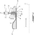
FIG. 2 is a partial cross sectional view of an engine mounting assembly for mounting the engine to an aircraft; -
FIG. 3 is a partial rear view of an aft mount bracket of the engine mounting assembly ofFig. 2 ; -
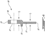
FIG. 4 is a cross sectional view of the aft mount bracket of the engine mounting assembly ofFig. 3 , taken through line IV-IV inFig. 3 ; and -
FIG. 5 is a partial cross sectional view of an engine mounting assembly for mounting the engine to an aircraft. -
FIG. 1 illustrates anaircraft engine 10, which in this case is a gas turbine engine, of a type preferably provided for use in subsonic flight, generally comprising in serial flow communication afan 12 through which ambient air is propelled, acompressor section 14 for pressurizing the air, acombustor 16 in which the compressed air is mixed with fuel and ignited for generating an annular stream of hot combustion gases, and aturbine section 18 for extracting energy from the combustion gases before they exist through anexhaust 20. Thecompressor section 14,combustor 16 andturbine section 18 are contained within anengine core 22, with the rotating components of thecompressor section 14 andturbine section 18 rotatable about acentral engine axis 11. - In the embodiment shown in
FIG. 1 , theengine 10 is a turbofan-type engine. Anengine casing 30 surrounds theengine core 22, forming anouter bypass duct 24. Theouter bypass duct 24 receives bypass air from the fan towards aninlet 26 of the engine and discharges the air at anoutlet 28 where it mixes with the core gas flow exiting theexhaust 20. WhileFIG. 1 depicts a turbofan-type engine, the present disclosure is applicable to other types of aircraft engines as well. - The
engine casing 30 may have anannular body 32 disposed about thecentral engine axis 11 and extending between afore end 34 adjacent theinlet 26 and anaft end 36 adjacent theoutlet 28. Irregular-shapedengine casing bodies 32, for instance to account for the shape of theengine core 22, may be contemplated as well. Theengine casing 30 may include afore flange 38 disposed about a circumference of thefore end 34 as well as anaft flange 40 disposed about a circumference of theaft end 36. Thefore flange 38 andaft flange 40 may include holes or other attachment features to enable mounting hardware to fasten to theengine casing 30. Theengine casing 30, and in turn theengine 10, may thus be secured to the airframe of an aircraft. - Referring to
FIG. 2 in addition toFIG. 1 , there is shown a mounting assembly 70 for anengine 10. In the shown case, the mounting assembly 70 is operable for attaching theengine casing 30 ofengine 10 to the airframe of an aircraft. In the shown case, where theengine 10 is a turbofan engine and theengine casing 30 forms anouter bypass duct 24 around theengine core 22, the mounting assembly 70 includes amount bracket 50 fastenable to an outer bypass duct (OBPD)aft flange 40 of theengine casing 30.Mount bracket 50 may be referred to as anaft mount bracket 50 in such cases where it is fastened to theaft end 36 of theengine casing 30. Anadditional component 60 may also be fastened to theflange 40 andaft mount bracket 50, for instance an exhaust manifold or a thrust reverser of theengine 10. In other cases, themount bracket 50 may be operable to fasten to other flanges of components of theengine 10 to the airframe of the aircraft, for instance thefore flange 38 of theengine casing 30, a lifting bracket or an engine build-up (EBU) unit. - The
aft flange 40 includes anannular wall 42 extending radially outwardly from theengine casing 30 towards a radiallyouter rim 44. In the shown case, theannular wall 42 has a constant thickness along its length towards the radiallyouter rim 44. A set ofholes 46 are circumferentially spaced apart about the circumference of theannular wall 42 and extend through theannular wall 42 from afront side 42a of theannular wall 42 to arear side 42b of theannular wall 42 relative to a direction D of the bypass air flowing through theouter bypass duct 24. The number and spacing ofholes 46 may vary, for instance based on the engine type and its support requirements. In some embodiments, theaft flange 40 may be integral with theengine casing 30. In other cases, theaft flange 40 may be a separate component that is welded or otherwise attached to theaft end 36 of theengine casing 30. - In the shown case, the
mount bracket 50 includes a fullyannular body 51, and as such may be referred to as a mounting ring. By fully annular, it is understood that the annular body 511 extends circumferentially interruptedly about thecenter axis 11. As discussed above, mountbracket 50 may be referred to as anaft mount bracket 50 in the present disclosure when mounted to theaft flange 40 of theengine casing 30, but it other cases themount bracket 50 may be mounted to other flanges within theengine 10. Theannular body 51 extends between a radiallyinner edge 52 and a radiallyouter edge 53. Themount bracket 50 includes a set ofholes 54 which are circumferentially spaced apart about the circumference of theannular body 51 and extend through theannular body 51. The number and spacing of theholes 54 may vary, and may coincide with the number and spacing of theholes 46 in theaft flange 40. In some cases, themount bracket 50 may have a different bolt pattern for itsholes 54 than the bolt pattern of theholes 46 in theflange 40, for instance to allow themount bracket 50 to be used for other flanges without requiring modifications. - The
mount bracket 50 further includes an at least partially load-reducingspigot 55 extending axially from theannular body 51 and disposed about the entire circumference of theannular body 51. Thespigot 55 protrudes from theannular body 51, illustratively at a radial position between the radiallyinner edge 52 and the radiallyouter edge 53, although other locations may be contemplated as well. As will be discussed in further detail below, thespigot 55 is operable to abut against the radiallyouter rim 44 of theaft flange 40 upon assembly. In the shown case, the axial length of thespigot 55 is approximately equal to the thickness of theaft flange 40, although other axial lengths for thespigot 55 may be contemplated as well. The radial positioning of thespigot 55 along theannular body 51 may vary, for instance based on the height of theaft flange 40. Referring additionally toFIG. 3 , which is an enhanced rear view of themount bracket 50, the relative radial positions of the spigot 55 (denoted by radius R55) and the holes 54 (denoted by radius R54) are shown. In various cases, the radial distance between thespigot 55 and theholes 54 may vary, for instance depending on the geometry of theaft flange 40. For clarity, theholes 54 are omitted fromFIG. 3 . - The
mount bracket 50 further includes one or more attachment points 56 positioned at various locations along the outer circumference of the radiallyouter edge 53 of theannular body 51. The attachment points 56, which may be referred to as local protrusions about the outer circumference of theannular body 51, may be machined to the radiallyouter edge 53 and include mountingholes 57 for mounting themount bracket 50 to the airframe of the aircraft. Referring additionally toFIG. 3 , in the shown case, the attachment points 56 include taperededges 58 where the attachment points 56 meet the radiallyouter edge 53 of theannular body 51, for instance to improve load distribution. The number and positioning of the attachment points 56 may vary, for instance based on the weight of theengine 10 being attached to the airframe and/or the bolt pattern at the airframe. WhileFIG. 3 shows two attachments points 56, it is understood thatFIG. 3 only depicts a portion of amount bracket 50, and that various numbers of attachment points 56 may be contemplated. In various embodiments, attachment points 56 may be regularly or irregularly positioned about the outer circumference of theannular body 51. - As discussed above, the
additional component 60 may be one of an exhaust manifold or a thrust reverser for theengine 10 that are fastened to theaft end 36 of theengine casing 30. Otheradditional components 60 may be contemplated as well. In other cases, themount bracket 50 may be fastened to the aft flange 40 (or another flange within the engine 10) with noadditional component 60 being concurrently attached. In the shown case, theadditional component 60 includes anannular body 61, aflange 62 having anannular wall 63 extending radially outwardly from theannular body 61, and holes 64 circumferentially spaced apart about the circumference of theannular wall 63 and extending through theannular wall 63. The number and spacing of theholes 64 may vary, and may generally correspond to the number and spacing ofholes aft flange 40 and mountbracket 50, respectively. - As shown in
FIG. 2 , in an exemplary assembly procedure, themount bracket 50 is placed axially betweenaft end 36 of theengine casing 30 and theadditional component 60, with theannular body 51 abuttingannular wall 42 of theaft flange 40 and theannular wall 63 of theadditional component 60. Themount bracket 50 is oriented so that theannular body 51 abuts therear side 42b of theannular wall 42, with thespigot 55 oriented in an axially rearward direction and radially abutting the radiallyouter rim 44 of theannular wall 42 in a spigot fit arrangement. The various components may then be rotated relative to each other so that theholes holes mount bracket 50 to theengine casing 30 and theadditional component 60, with the spigot bearing at least some of the load imparted by the fasteners. Other assembly steps and configurations may be contemplated as well. For instance, in another embodiment that does not include theadditional component 60, themount bracket 50 may be positioned so that theannular body 51 abuts thefront side 42a of theannular wall 42 with thespigot 55 extending in an axially rearward direction as it radially abuts the radiallyouter rim 44. Other arrangements may be contemplated as well. - Referring additionally to
FIG. 4 , in some embodiments the axial thickness of theannular body 51 may vary between the radiallyinner edge 52 and the radiallyouter edge 53. In the shown case, theannular body 51 has first section with a first thickness T1 and a second section with a second thickness T2 at its radiallyouter edges 53 at the circumferential locations of the attachment points 56, the second thickness T2 being greater than the first thickness T1. As shown inFIG. 4 , the second section having the thickness T2 may commence radially outwardly of the spigot and extend to the radiallyouter edge 53 of eachattachment point 56, and include the tapered edges 58. In such cases, the entire portion of theannular body 51 positioned radially inwardly of thespigot 55 would have thickness T1. In other cases, the first section of theannular body 51 having thickness T1 may partially extend radially outwardly of thespigot 55. The greater thickness at the attachment points 56 may allow the attachment points 56 to withstand the loads imparted by their attachment to the airframe of the aircraft. In addition, various types of bearings may be passed through the mountingholes 57 to attach the attachment points 56 to the airframe, and thus the greater thickness at the attachment points 56 may accommodate the width of said bearings. The remainder of theannular body 51 may be of lesser first thickness T1 as the loads imparted by theaft flange 40,additional component 60 and attachment points 56 are distributed about the entire circumference of theannular body 51. In addition, thespigot 55 may be least partially load bearing, lightening the load requiring theannular body 51 to bear. - Referring to
FIG. 5 , there is shown another embodiment of a mounting assembly 70 for anengine 10, with like reference numerals used hereinafter to identify like components. In the depicted embodiment, the mounting assembly 70 is operable for attaching theengine casing 30 ofengine 10 to the airframe of an aircraft, and includes amount bracket 50 fastenable to an outer bypass duct (OBPD) aftflange 40 of theengine casing 30. In the depicted embodiment, thespigot 55 protrudes axially from theannular body 51 at the radiallyinner edge 52 of theannular body 51. In addition, thespigot 55 is operable to radially abut a radiallyinner rim 48 of theannular wall 42 of theaft flange 40. Illustratively, theaft flange 40 includes anindentation 49 at the radiallyinner rim 48 to accommodate thespigot 55. In some cases, for instance where theaft flange 40 is a separate component from theengine casing 30, theaft flange 40 may be positioned to overhang from theaft end 36 of theengine casing 30 to form theindentation 49. In other cases, for instance where theaft flange 40 is integrated with theengine casing 30, theindentation 49 may be formed as a cutout in theaft end 36 of theengine casing 30. - In various cases, by providing a
single mount bracket 50 with aannular body 51, in lieu of multiple discrete aft engine mounting brackets that are typically used, the load may be able to be better circumferentially distributed (and thus optimized), thereby reducing stress concentrations in comparison with said typically-used multiple aft engine mounting brackets. In addition, theintegrated spigot 55 may relieve the fasteners passing through theholes 54 of shear loads induced by themount bracket 50. In other words, at least some of the radial shear loads to which the fasteners would be otherwise exposed may be taken by thespigot 55 and/or themount bracket 50 itself. Thus, it may be possible to use fewer and/or smaller fasteners due to the reduce loads they are required to sustain. - In various cases, the
mount bracket 50 may be made from a fire-resistant material (e.g., steel). As such, the herein described mount bracket may improve fire resistance by assuring circumferential integrity of composite oraluminum engine casings 30 at the aft mount plane, in case of fire. - In various cases, by providing an
aft mount bracket 50 with aannular body 51, the attachment points 56 may be positioned at any point about the outer circumference of theannular body 51 based on the mounting requirements with the airframe of the aircraft, regardless of the bolt pattern of theholes 46 in theaft flange 40. - In some cases, the
annular body 51 may not include aspigot 55. For instance, based on the size and weight of theengine casing 30, theannular body 51 may be capable of distributing the loads from the fasteners so that the at least partial load bearing provided by thespigot 55 is not required. In addition, in such cases the attachment points 56 may be positioned independently of the bolt pattern of theholes 4 in theaft flange 40. In other cases, for instance as shown inFIGS. 2-4 , theengine casing 30 may be sized such that the at least partial load bearing provided by thespigot 55 is required. - The embodiments described in this document provide non-limiting examples of possible implementations of the present technology. Upon review of the present disclosure, a person of ordinary skill in the art will recognize that changes may be made to the embodiments described herein without departing from the scope of the present technology. Yet further modifications could be implemented by a person of ordinary skill in the art in view of the present disclosure, which modifications would be within the scope of the present technology.
Claims (10)
- An assembly (70) for mounting an aircraft engine (10) to an aircraft, comprising:an engine casing flange (40) having a first annular wall (42) extending circumferentially about a center axis (11) and extending radially to terminate at an annular rim (44; 48), a first set of holes (46) in the first annular wall (42) being circumferentially spaced apart and extending axially through the first annular wall (42);a second flange (62) of an additional engine component (60) mounted aft of the engine casing (30), the second flange (62) having a body (61) defined about the center axis (11) with a second annular wall (63) extending radially outwardly from the body (61), the second flange (62) having a second set of holes (64) circumferentially spaced apart and extending axially through the second annular wall (63);an aft mount bracket (50) having an annular body (51) extending uninterrupted about the center axis (11) and a third set of holes (54) circumferentially spaced apart and extending axially through the annular body (51), the aft mount bracket (50) having a spigot (55) extending axially from the annular body (51), the spigot (55) extending circumferentially about an entire circumference of the annular body (51), the aft mount bracket (50) further including one or more attachment points (56) extending radially from a radially outer edge (53) of the annular body (51), the one or more attachment points (56) having mounting holes (57) adapted for mounting the aft mount bracket (50) to the aircraft, wherein the aft mount bracket (50) axially disposed between the engine casing flange (40) and the additional engine component (60), with the first set of holes (46), the second set of holes (64) and the third set of holes (54) circumferentially aligned and the spigot (55) radially abutting the annular rim (44; 48) of the engine casing flange (40); andfasteners received through the first set of holes (46), the second set of holes (64), and the third set of holes (54), the fasteners operable for axially retaining the engine casing flange (40), the additional engine component (60) and the aft mount bracket ring.
- The assembly (70) as defined in claim 1, wherein the aft mount bracket (50) includes a first section having a first axial thickness (T1) and a second section comprising the attachment points (56) having a second axial thickness (T2) greater than the first axial thickness (T1).
- The assembly (70) as defined in claim 2, wherein the spigot (55) is positioned radially outwardly from the third set of holes (54) and the first section having the first axial thickness (T1) is positioned radially inwardly of the spigot (55).
- The assembly (70) as defined in any one of claims 1 to 3, wherein the spigot (55) is positioned radially outwardly from the third set of holes (54) on the annular body (51) of the aft mount bracket (50), the spigot (55) radially abutting a radially outer rim (44) of the engine casing flange.
- The assembly (70) as defined in claim 1 or 2, wherein the spigot (55) is positioned at a radially inner edge (52) of the annular body (51) of the aft mount bracket (50), the spigot (55) radially abutting a radially inner rim (48) of the engine casing flange (40).
- The assembly (70) as defined in any one of the preceding claims, wherein a number and arrangement of the first set of holes (46) in the first annular wall (42) of the engine casing flange (40) correspond to a number and arrangement of the third set of holes (54) in the annular body (51) of the aft mount bracket (50).
- The assembly (70) as defined in any one of the preceding claims, wherein the additional engine component (60) is a thrust reverser of the aircraft engine (10) or an exhaust duct of the aircraft engine (10).
- The assembly (70) as defined in any one of the preceding claims, wherein the attachment points (56) include tapered edges (58) joining the attachment points (56) to the radially outer edge (53) of the annular body (51).
- The assembly (70) as defined in any one of the preceding claims, wherein the spigot (55) is at least partially load bearing.
- An aircraft engine (10), comprising:
an engine casing (30) with an aft flange (40) on an outer bypass duct (24), the aft flange (40) being the engine casing flange as defined in any one of the preceding claims.
Applications Claiming Priority (1)
| Application Number | Priority Date | Filing Date | Title |
|---|---|---|---|
| US17/395,049 US11643218B2 (en) | 2021-08-05 | 2021-08-05 | AFT engine mount ring with spigot |
Publications (1)
| Publication Number | Publication Date |
|---|---|
| EP4129824A1 true EP4129824A1 (en) | 2023-02-08 |
Family
ID=82846382
Family Applications (1)
| Application Number | Title | Priority Date | Filing Date |
|---|---|---|---|
| EP22189124.5A Withdrawn EP4129824A1 (en) | 2021-08-05 | 2022-08-05 | Aft engine mount ring with spigot |
Country Status (2)
| Country | Link |
|---|---|
| US (1) | US11643218B2 (en) |
| EP (1) | EP4129824A1 (en) |
Families Citing this family (6)
| Publication number | Priority date | Publication date | Assignee | Title |
|---|---|---|---|---|
| US12264595B2 (en) | 2023-06-29 | 2025-04-01 | Pratt & Whitney Canada Corp. | Turbine support case having axial spokes |
| US12515807B2 (en) * | 2024-01-19 | 2026-01-06 | Pratt & Whitney Canada Corp. | Bolted connection between mounting bracket and aircraft engine case(s) |
| US12595750B1 (en) | 2024-10-10 | 2026-04-07 | Pratt & Whitney Canada Corp. | Turbine support case with axial spokes and brackets |
| US12486788B1 (en) | 2024-10-10 | 2025-12-02 | Pratt & Whitney Canada Corp. | Turbine support case supported by stopping ribs |
| US12416249B1 (en) | 2024-10-10 | 2025-09-16 | Pratt & Whitney Canada Corp. | Turbine support case with axial spokes and heat shields |
| US12467473B1 (en) | 2024-11-11 | 2025-11-11 | Pratt & Whitney Canada Corp. | Aircraft engine including diffuser secured to a bearing housing |
Citations (3)
| Publication number | Priority date | Publication date | Assignee | Title |
|---|---|---|---|---|
| US20150075177A1 (en) * | 2013-09-18 | 2015-03-19 | Snecma | Device for suspending a casing, a turbine engine and a propulsion assembly |
| EP3299590A1 (en) * | 2016-09-06 | 2018-03-28 | Safran Aircraft Engines | Intermediate casing of a turbomachine turbine |
| FR3097903A1 (en) * | 2019-06-28 | 2021-01-01 | Safran Aircraft Engines | CASING FOR AN AIRCRAFT TURBOMACHINE |
Family Cites Families (7)
| Publication number | Priority date | Publication date | Assignee | Title |
|---|---|---|---|---|
| GB675300A (en) | 1949-05-24 | 1952-07-09 | Rolls Royce | Improvements in or relating to exhaust ducting of gas-turbine engines |
| FR2732074B1 (en) * | 1995-03-21 | 1997-06-06 | Aerospatiale | DOUBLE FLOW TURBOREACTOR WITH A FLOATING PLATFORM |
| US6843449B1 (en) * | 2004-02-09 | 2005-01-18 | General Electric Company | Fail-safe aircraft engine mounting system |
| FR2965550B1 (en) | 2010-10-05 | 2012-11-02 | Airbus Operations Sas | SPIGOT-TYPE ATTACHMENT PROVIDED WITH AT LEAST ONE MEANS FOR MEASURING THE EFFORT GENERATED BY AN AIRCRAFT ENGINE |
| US9200531B2 (en) * | 2012-01-31 | 2015-12-01 | United Technologies Corporation | Fan case rub system, components, and their manufacture |
| US9498850B2 (en) * | 2012-03-27 | 2016-11-22 | Pratt & Whitney Canada Corp. | Structural case for aircraft gas turbine engine |
| US10814995B2 (en) | 2017-08-29 | 2020-10-27 | Spirit Aerosystems, Inc. | High-mounted aircraft nacelle |
-
2021
- 2021-08-05 US US17/395,049 patent/US11643218B2/en active Active
-
2022
- 2022-08-05 EP EP22189124.5A patent/EP4129824A1/en not_active Withdrawn
Patent Citations (3)
| Publication number | Priority date | Publication date | Assignee | Title |
|---|---|---|---|---|
| US20150075177A1 (en) * | 2013-09-18 | 2015-03-19 | Snecma | Device for suspending a casing, a turbine engine and a propulsion assembly |
| EP3299590A1 (en) * | 2016-09-06 | 2018-03-28 | Safran Aircraft Engines | Intermediate casing of a turbomachine turbine |
| FR3097903A1 (en) * | 2019-06-28 | 2021-01-01 | Safran Aircraft Engines | CASING FOR AN AIRCRAFT TURBOMACHINE |
Also Published As
| Publication number | Publication date |
|---|---|
| US20230044678A1 (en) | 2023-02-09 |
| US11643218B2 (en) | 2023-05-09 |
Similar Documents
| Publication | Publication Date | Title |
|---|---|---|
| US11643218B2 (en) | AFT engine mount ring with spigot | |
| US11118481B2 (en) | Ceramic matrix composite turbine exhaust assembly for a gas turbine engine | |
| US8092169B2 (en) | Integrated inlet fan case | |
| US8596972B2 (en) | Attachment interface for a gas turbine engine composite duct structure | |
| CA2600818C (en) | Exhaust duct and tail cone attachment of aircraft engines | |
| US10036276B2 (en) | High durability turbine exhaust case | |
| EP3396113B1 (en) | Intershaft seal with support linkage | |
| US10060631B2 (en) | Hybrid diffuser case for a gas turbine engine combustor | |
| EP3022422B1 (en) | Swirler mount interface for gas turbine engine combustor | |
| US6401447B1 (en) | Combustor apparatus for a gas turbine engine | |
| US10443447B2 (en) | Doubler attachment system | |
| EP3913197B1 (en) | Assemblies for transferring compressive loads in flanges of composite gas turbine engine components | |
| EP3091215A1 (en) | Attachment assembly and gas turbine engine with attachment assembly | |
| EP3022491B1 (en) | Swirler mount interface for gas turbine engine combustor | |
| US20230112117A1 (en) | Combustor swirler to pseudo-dome attachment and interface with a cmc dome | |
| EP4086437A1 (en) | Vane system with continuous support ring | |
| EP3026247B1 (en) | Composite fan housing assembly of a turbofan engine and method of manufacture | |
| EP1809893B1 (en) | Stator for a jet engine, a jet engine comprising such a stator, and an aircraft comprising the jet engine | |
| GB2558566A (en) | A combustion chamber arrangement | |
| EP3730738B1 (en) | Turbine assembly for a gas turbine engine with ceramic matrix composite vane | |
| EP3760843B1 (en) | Duct assembly for a gas turbine engine | |
| EP2910752B1 (en) | Fuel manifold fitting with integral support for a gas turbine engine and method of mounting a fuel supply manifold assembly | |
| US20260132722A1 (en) | Damped fairing assembly | |
| EP4696873A1 (en) | Overlap holder for segmented liner of turbomachine component | |
| US20250236404A1 (en) | Bolted connection between mounting bracket and aircraft engine case(s) |
Legal Events
| Date | Code | Title | Description |
|---|---|---|---|
| PUAI | Public reference made under article 153(3) epc to a published international application that has entered the european phase |
Free format text: ORIGINAL CODE: 0009012 |
|
| STAA | Information on the status of an ep patent application or granted ep patent |
Free format text: STATUS: THE APPLICATION HAS BEEN PUBLISHED |
|
| AK | Designated contracting states |
Kind code of ref document: A1 Designated state(s): AL AT BE BG CH CY CZ DE DK EE ES FI FR GB GR HR HU IE IS IT LI LT LU LV MC MK MT NL NO PL PT RO RS SE SI SK SM TR |
|
| STAA | Information on the status of an ep patent application or granted ep patent |
Free format text: STATUS: THE APPLICATION IS DEEMED TO BE WITHDRAWN |
|
| 18D | Application deemed to be withdrawn |
Effective date: 20230809 |