EP4129820A1 - Unmanned flying body control assistance system and unmanned flying body control assistance method - Google Patents
Unmanned flying body control assistance system and unmanned flying body control assistance method Download PDFInfo
- Publication number
- EP4129820A1 EP4129820A1 EP20926430.8A EP20926430A EP4129820A1 EP 4129820 A1 EP4129820 A1 EP 4129820A1 EP 20926430 A EP20926430 A EP 20926430A EP 4129820 A1 EP4129820 A1 EP 4129820A1
- Authority
- EP
- European Patent Office
- Prior art keywords
- wind condition
- simulation
- wind
- simulation result
- data
- Prior art date
- Legal status (The legal status is an assumption and is not a legal conclusion. Google has not performed a legal analysis and makes no representation as to the accuracy of the status listed.)
- Granted
Links
Images




Classifications
-
- G—PHYSICS
- G05—CONTROLLING; REGULATING
- G05D—SYSTEMS FOR CONTROLLING OR REGULATING NON-ELECTRIC VARIABLES
- G05D1/00—Control of position, course, altitude or attitude of land, water, air or space vehicles, e.g. using automatic pilots
- G05D1/02—Control of position or course in two dimensions
- G05D1/0202—Control of position or course in two dimensions specially adapted to aircraft
- G05D1/0204—Control of position or course in two dimensions specially adapted to aircraft to counteract a sudden perturbation, e.g. cross-wind, gust
-
- G—PHYSICS
- G01—MEASURING; TESTING
- G01C—MEASURING DISTANCES, LEVELS OR BEARINGS; SURVEYING; NAVIGATION; GYROSCOPIC INSTRUMENTS; PHOTOGRAMMETRY OR VIDEOGRAMMETRY
- G01C21/00—Navigation; Navigational instruments not provided for in groups G01C1/00 - G01C19/00
- G01C21/20—Instruments for performing navigational calculations
-
- G—PHYSICS
- G01—MEASURING; TESTING
- G01W—METEOROLOGY
- G01W1/00—Meteorology
- G01W1/10—Devices for predicting weather conditions
-
- B—PERFORMING OPERATIONS; TRANSPORTING
- B64—AIRCRAFT; AVIATION; COSMONAUTICS
- B64U—UNMANNED AERIAL VEHICLES [UAV]; EQUIPMENT THEREFOR
- B64U2201/00—UAVs characterised by their flight controls
- B64U2201/10—UAVs characterised by their flight controls autonomous, i.e. by navigating independently from ground or air stations, e.g. by using inertial navigation systems [INS]
Definitions
- the present invention relates to the technology of unmanned flying object control assistance systems, and unmanned flying object control assistance methods.
- Drones unmanned flying objects
- Drones have been used increasingly for inspecting windmills used for wind power generation, and the like.
- a drone captures images of a windmill, and, on the basis of the images, an inspector makes an assessment as to whether or not maintenance is necessary or the like.
- a drone is used for such uses, it is necessary to capture high-resolution images, and so it is necessary for the drone to fly and stay in the air stably.
- drones are small-sized and lightweight, there are problems that they are easily influenced by the wind, and particularly are easily influenced by wind condition changes such as gusts.
- Patent Literature 1 is disclosed.
- Patent Literature 1 discloses a flight route calculation system, a flight route calculation program, and an unmanned aerial vehicle route control method that are aimed to "make it possible for a drone to fly without requiring manual maneuvering, and taking influences of the wind into consideration.
- An unmanned aerial vehicle flight management system 1 includes: a three-dimensional map data storage section 172 that stores three-dimensional map data in the horizontal direction, and height direction of a space where there are no ground objects, and an unmanned aerial vehicle 6 can fly; a current position acquiring section 175 that acquires a current position; a transport instruction acquiring section 166 that acquires a destination; a route calculating section 167 that calculates a flyable route in the map data from the current position to the destination; a lidar data acquiring section 121 that acquires wind condition data; a dangerous wind condition area assessing section 123 that calculates, from the wind condition data, an alert area where flights had better be avoided; and a route recalculating section 164 that recalculates a route that avoids the alert area
- Patent Literature 1 WO 2020/013153
- Patent Literature 1 describes predictions of wind conditions in the near future from measured wind condition data, specific techniques of the predictions are not described.
- the present invention has been made in view of such a background, and an object of the present invention is to enable stable flights of an unmanned flying object.
- an unmanned flying object control assistance system includes: a simulation processing section that, for each piece of a plurality of pieces of virtual wind condition information, executes a simulation of a flow of air of a geographical point where an unmanned flying object flies, and outputs a simulation result which is a result of the simulation; a simulation result acquiring section that, on a basis of measured wind condition information which is information about a measured wind condition, acquires the simulation result of the virtual wind condition information corresponding to the measured wind condition information; and an output section that outputs the acquired simulation result.
- Fig. 1 is a figure depicting a configuration example of a drone control assistance system 1.
- the drone control assistance system 1 has a simulation apparatus 100, and a wind condition estimating apparatus 300. Note that the drone control assistance system 1 may include an analysis result DB 200.
- the simulation apparatus 100 acquires past weather data 601 from a weather center B1, and acquires terrain profile data 602 from a geographic center B2. Then, the simulation apparatus 100 performs a simulation (wind condition simulation) of wind conditions in a wind-condition estimated area on the basis of the data.
- wind conditions are wind speeds, and wind directions.
- the wind-condition estimated area is an area where wind conditions are estimated for flying a drone 500. In other words, the wind-condition estimated area is an area for flying the drone 500.
- the simulation apparatus 100 performs a flow field feature analysis of wind conditions of the wind-condition estimated area obtained as a result of the wind condition simulation.
- the flow field feature analysis is described later. It is supposed here that, as a result of the flow field feature analysis, an analysis result set 750 is generated. The analysis result set 750 is described later. Then, the simulation apparatus 100 stores, in the analysis result DB 200, the generated analysis result (here, the analysis result set 750).
- the wind condition estimating apparatus 300 acquires the analysis result from the analysis result DB 200. Then, on the basis of the acquired analysis result (here, the analysis result set 750), the wind condition estimating apparatus 300 estimates wind conditions of the wind-condition estimated area of a time after the passage of predetermined time from the current time.
- the weather forecast data 603 is acquired from the weather center B1 or the like.
- the measured wind condition data 604 is acquired from a wind speed sensor or the like which is not depicted, but is included in a windmill WM.
- the wind condition estimating apparatus 300 outputs, to a drone control apparatus 400, data (estimated wind condition data 605) of the estimated wind conditions.
- an operator P1 controls the drone 500 by operating the drone control apparatus 400.
- the estimated wind condition data 605 output to the drone control apparatus 400 is displayed on a display apparatus which is not depicted, but is included in the drone control apparatus 400.
- the operator P1 performs control (maneuvering) of the drone 500.
- Fig. 2 is a functional block diagram of the simulation apparatus 100 in the present embodiment.
- Fig. 1 is referred to as appropriate.
- the simulation apparatus 100 includes at least a memory 110, a CPU (Central Processing Unit) 121, and a transmitting/receiving apparatus 122.
- a memory 110 includes at least a central processing unit (CPU) 121, and a central processing unit (CPU) 121.
- CPU Central Processing Unit
- the transmitting/receiving apparatus 122 receives the past weather data 601 from the weather center B1, receives the terrain profile data 602 from the geographic center B2, and so on. In addition, the transmitting/receiving apparatus 122 transmits the analysis result set 750, and the like to the analysis result DB 200.
- a program stored on a storage apparatus which is not depicted is loaded onto the memory 110, and the loaded program is executed by the CPU 121.
- a data acquiring section 111, a simulation processing section 112, an analysis processing section 113, and a storage processing section 114 are realized.
- the data acquiring section 111 acquires the past weather data 601 from the weather center B1, acquires the terrain profile data 602 from the geographic center B2, and so on.
- the simulation processing section 112 calculates virtual wind condition data 741 (see Fig. 8 ) of time t. In addition, on the basis of the calculated virtual wind condition data 741, the simulation processing section 112 performs a simulation (wind condition simulation) of wind conditions of the wind-condition estimated area of time t+1.
- the virtual wind condition data 741 is described later, and is input data in the wind condition simulation.
- time t+1 means a time which is predetermined time after time t.
- the analysis processing section 113 performs a flow field feature analysis process such as principal component analysis (proper orthogonal decomposition) of results of the simulation by the simulation processing section 112.
- the storage processing section 114 stores the results obtained by the analysis processing section 113 in the analysis result DB 200 in association with weather conditions, and the like in the virtual wind condition data 741, and the past weather data 601.
- Fig. 3 is a functional block diagram of the wind condition estimating apparatus 300 in the present embodiment.
- Fig. 1 is referred to as appropriate.
- the wind condition estimating apparatus 300 includes at least a memory 310, a CPU 321, and a transmitting/receiving apparatus 322.
- the transmitting/receiving apparatus 322 receives the weather forecast data 603 from the weather center B1, receives the measured wind condition data 604, which is data of measured wind conditions, and so on. In addition, the transmitting/receiving apparatus 322 acquires the analysis result set 750 from the analysis result DB 200, outputs, to the drone control apparatus 400, the estimated wind condition data (the estimated wind condition data 605) of the wind-condition estimated area, and so on.
- a program stored on a storage apparatus which is not depicted is loaded onto the memory 310, and the loaded program is executed by the CPU 321.
- a data acquiring section 311, an analysis result acquiring section 312, a wind condition estimating section 313, and an output processing section 314 are realized.
- the data acquiring section 311 acquires the weather forecast data 603 from the weather center B1, acquires the measured wind condition data 604 from the wind speed sensor (not depicted) included in the windmill WM or the like, and so on.
- the analysis result acquiring section 312 acquires the analysis result set 750 from the analysis result DB 200.
- the wind condition estimating section 313 estimates wind conditions of the wind-condition estimated area.
- the output processing section 314 outputs, to the drone control apparatus 400, data (the estimated wind condition data 605) of the estimated wind conditions.
- Fig. 4 is a flowchart depicting the procedure of processes performed by the simulation apparatus 100 in the present embodiment. Details of processes at Steps S101 to S105 are described later. In addition, Fig. 1 to Fig. 3 are referred to as appropriate.
- the data acquiring section 111 acquires the past weather data 601 from the weather center B1, and acquires the terrain profile data 602 from the geographic center B2 (S101).
- the simulation processing section 112 calculates the virtual wind condition data 741 (see Fig. 8 ) of a geographical point (S102).
- the virtual wind condition data 741 is described later.
- the simulation processing section 112 performs a simulation (wind condition simulation) of wind conditions of the wind-condition estimated area (S103).
- the analysis processing section 113 performs a flow field feature analysis process on results of the process at Step S103 (S104).
- a technique used for the flow field feature analysis process is sy component analysis (proper orthogonal decomposition), Fourier analysis or the like as described before.
- the storage processing section 114 stores, in the analysis result DB 200, results (analysis results; the analysis result set 750 in the present embodiment) of the flow field feature analysis process (S105).
- the simulation apparatus 100 performs the processes at Steps S101 to S105 on various pieces of virtual wind condition data 741. Then, the simulation apparatus 100 stores, in the analysis result DB 200, the analysis results (analysis result set 750) in association with a corresponding piece of the virtual wind condition data 741, and weather conditions used for calculations of the piece of the virtual wind condition data 741.
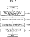
- Fig. 5 is a flowchart depicting the procedure of processes performed by the wind condition estimating apparatus 300 in the present embodiment. Details of processes at Steps S201 to S204 are described later. In addition, Fig. 1 to Fig. 3 are referred to as appropriate.
- the data acquiring section 311 acquires the weather forecast data 603, and the measured wind condition data 604 via the transmitting/receiving apparatus 322 (S201).
- the weather forecast data 603 is acquired from the weather center B1
- the measured wind condition data 604 is acquired from the wind speed sensor (not depicted) included in the windmill WM or the like, for example.
- the analysis result acquiring section 312 acquires an analysis result set 750 matching weather conditions of the acquired measured wind condition data 604, and weather forecast data 603 (S202).
- the wind condition estimating section 313 estimates wind conditions of the wind-condition estimated area of a time after the passage of predetermined time from the current time (S203) . If the current time is time t, the time which is the predetermined time after the current time here means a time equivalent to time t+1.
- the output processing section 314 outputs the estimated wind condition data (estimated wind condition data 605) of the wind-condition estimated area (S204).
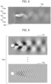
- Fig. 6 is a figure depicting an example of the past weather data 601 acquired at Step S101 in Fig. 4 .
- Fig. 6 depicts the past weather data 601 about Japan, and its surrounding areas.
- Fig. 6 depicts wind conditions in the past weather data 601. That is, reference character 711 denotes arrows representing wind directions, and shading represents wind speeds. That is, the darker the shading is, the faster the wind speed is, and the brighter the shading is, the slower the wind speed is.
- the past weather data 601 of an area represented by reference character 713 where the target windmill WM of an estimation of wind conditions is installed is depicted in Fig. 7 , which is described later.
- Fig. 7 depicts the past weather data 601 of the area represented by reference character 713 in Fig. 6 .
- reference character 721 denotes the contour of the terrain profile
- reference character 722 denotes arrows representing wind directions.
- the shading in Fig. 7 represents wind speeds. That is, the darker the shading is, the faster the wind speed is, and the brighter the shading is, the slower the wind speed is.
- reference character 723 denotes the wind-condition estimated area.
- Fig. 8 is a figure depicting the virtual wind condition data 741 calculated at Step S102 in Fig. 4 , and results of the wind condition simulation of the wind-condition estimated area performed at Step S103.
- the virtual wind condition data 741 is calculated at Step S102 in Fig. 4 .
- the virtual wind condition data 741 is calculated by the simulation processing section 112 on the basis of the past weather data 601 like the ones depicted in Fig. 6, and Fig. 7 , the terrain profile data 602, data such as temperature or humidity in the past weather data 601, past wind conditions, and the like.
- reference character 742 denotes the windmill WM.
- wind conditions 743 that are observed at a downwind location (the wind-condition estimated area) of the windmill WM at time t+1 are obtained through the wind condition simulation.
- the shading represents wind speeds. The darker the shading is, the faster the wind speed is, and the brighter the shading is, the slower the wind speed is.
- there is a disturbance of air such as a vortex of air at the downwind location (the wind-condition estimated area) of the windmill WM. If the drone 500 is caught in such a disturbance (vortex) of air, the drone 500 loses the balance significantly, and it becomes difficult to perform image-capturing, and the like.
- Fig. 9 is a figure depicting results of the flow field feature analysis process performed at Step S104 in Fig. 4 .
- Fig. 9 depicts an example in which the principal component analysis is applied to the simulation results depicted as the wind conditions 743 in Fig. 8 .
- the first mode to the n-th mode of analysis results are obtained.
- reference character 751 denotes the first mode of analysis results
- reference character 752 denotes the n-th mode of analysis results. Whereas only the first mode, and n-th mode of analysis results are depicted here, actually, there are the second mode, third mode, ... (n-1)-th mode of analysis results between the first mode of analysis results, and the n-th mode of analysis results.
- the first mode of analysis results denoted by reference character 751 includes a large vortex of air
- the n-th mode of analysis results denoted by reference character 752 includes small flow velocity changes.
- analysis result set 750 One set of the first mode (reference character 751), second mode, ... (n-1)-th mode, and n-th mode (reference character 752) of analysis results generated on the basis of the same simulation results is referred to as an analysis result set 750.
- the analysis processing section 113 also calculates a system matrix A for reconstructing the wind conditions 743 in Fig. 8 from the analysis result set 750. Note that the calculation of the system matrix A can be performed very simply.
- the storage processing section 114 stores the analysis result set 750 depicted in Fig. 9 in the analysis result DB 200.
- the storage processing section 114 stores, in association with the analysis result set 750 and in the analysis result DB 200, the virtual wind condition data 741 in Fig. 8 , the system matrix A, and weather conditions such as a temperature or a humidity obtained from the past weather data 601. Note that by storing the analysis result set 750 in the analysis result DB 200 as depicted in Fig. 9 , the volume of data stored in the analysis result DB 200 can be reduced.
- the weather forecast data 603 is acquired, and the measured wind condition data 604 is acquired.
- the measured wind condition data 604 is measured wind condition data equivalent to the virtual wind condition data 741 in Fig. 8 . That is, the measured wind condition data 604 is data related to the wind blowing toward the windmill WM.
- the analysis result acquiring section 312 acquires weather conditions such as a temperature or a humidity obtained from the measured wind condition data 604, and the weather forecast data 603, an analysis result set 750 associated with similar virtual wind condition data 741, and weather conditions, and the system matrix A. Note that the system matrix A may be calculated at this timing.
- the wind condition estimating section 313 performs a process according to a reduced order model to thereby reconstruct the wind conditions 743 in Fig. 8 .
- wind conditions of the wind-condition estimated area of a time after the passage of predetermined time from the current time are estimated.
- the time after the passage of predetermined time here means a time equivalent to time t+1, supposing that the current time is time t.
- the output processing section 314 outputs, to the drone control apparatus 400, data (the estimated wind condition data 605) of the wind conditions of the wind-condition estimated area estimated by the recovery.
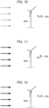
- Fig. 10 to Fig. 12 are figures depicting examples of execution by the drone control assistance system 1 according to the present embodiment.
- Fig. 10 depicts the flight condition of the drone 500 of the current time
- Fig. 11, and Fig. 12 depict the flight condition of the drone 500 of times each after the passage of predetermined time from the current time.
- Fig. 10 It is supposed, as depicted in Fig. 10 , that the drone 500 is flying by the windmill WM for capturing images in the maintenance of the windmill WM. It is supposed in Fig. 10 that a wind which does not influence the flight of the drone 500 is blowing from the left side on the paper surface (thin arrows in Fig. 10 ).
- analysis result sets 750 are stored in the analysis result DB 200 in association with various wind conditions, and weather conditions. Then, the wind condition estimating apparatus 300 searches for an analysis result set 750 in accordance with wind conditions, and weather conditions of an upwind location of the windmill WM of the current time.
- the wind condition estimating apparatus 300 can reconstruct wind conditions of the wind-condition estimated area (e.g. a downwind location of the windmill WM) on the basis of the analysis result set 750 found through the search. Because the reconstruction takes little time, substantially, it is required only to search for and acquire a result that has been obtained already through wind condition simulations, and the influence of wind condition changes such as a gust can be output in real time.
- the wind-condition estimated area e.g. a downwind location of the windmill WM
- the operator P1 can recognize in advance a disturbance of the air generated by a gust or the like, and can perform maneuvering of the drone 500 according to the gust or the like.
- a stable flight of the drone 500 can be realized, and stable image-capturing can be performed in the maintenance or the like.
- Fig. 13 is a figure depicting another application example of the drone control assistance system 1 according to the present embodiment.
- Fig. 13 is different from Fig. 1 in that autonomous control of a drone 500a is performed.
- the wind condition estimating apparatus 300 outputs the estimated wind condition data 605 to the drone 500a, and a drone monitoring apparatus 400a.
- the drone 500a has an optimal control computing section 501, a control section 502, and a posture sensor 503.
- the optimal control computing section 501 calculates control data of a time after the passage of predetermined time from the current time on the basis of the current posture data obtained by the posture sensor 503, and the estimated wind condition data 605 input from the wind condition estimating apparatus 300.
- the control section 502 of the drone 500a performs posture control of the drone 500a on the basis of the calculated control data of the time after the passage of the predetermined time.
- an observer P2 monitors whether the drone 500a is performing appropriate autonomous control by monitoring the estimated wind condition data 605 acquired from the wind condition estimating apparatus 300 on the drone monitoring apparatus 400a.
- the influence of wind condition changes such as a gust can be output almost in real time, and so it becomes possible for the drone 500 to fly and stay in the air stably. Thereby, stable images can be obtained in image-capturing or the like in maintenance.
- the operator P1 can recognize in advance estimated wind conditions of a wind-condition estimated area, and so does not necessarily have to be an expert to maneuver the drone 500.
- Step S104 in Fig. 4 by performing the flow field feature analysis (Step S104 in Fig. 4 ), the amount of data of analysis results can be compressed. Thereby, the volume of data stored in the analysis result DB 200 can be reduced.
- the simulation processing section 112 generates the virtual wind condition data 741 on the basis of the past weather data 601, and terrain profile data 602 of the wind-condition estimated area. Then, the simulation processing section 112 performs a wind condition simulation on the basis of the generated virtual wind condition data 741. Thereby, the wind condition simulation can be performed in accordance with conditions close to actual wind conditions, and the precision of the wind condition simulation can be enhanced.
- the drone control assistance system 1 may be used for control assistance of the drone 500 around a structure such as a bridge or a plant.
- the measured wind condition data 604 is acquired from a wind speed center (not depicted) included in the windmill WM
- the wind speed sensor may be installed on the ground or a building other than the windmill WM, for example, as long as the wind speed sensor is installed near the windmill WM.
- Step S104 in Fig. 4 is not executed, and the simulation result (the wind conditions 743 in Fig. 8 ) is stored in an analysis result DB 740 in association with virtual wind condition data 471, weather conditions, and the like.
- the analysis result acquiring section 312 acquires a simulation result on the basis of the current wind conditions, and weather conditions. Thereafter, the simulation result acquired by the output processing section 314 is output to the drone control apparatus 400, the drone monitoring apparatus 400a, and a drone 400a.
- the configuration, functionalities, processing sections 111 to 114, and 311 to 314, analysis result DB 200, and the like that are described before may partially or entirely be realized by hardware by being designed on an integrated circuit, and so on, for example.
- the configuration, functionalities, and the like that are described before may be realized by software by processors such as the CPUs 121, and 321 interpreting and executing programs to realize the functionalities.
- Information such as programs, tables or files that realize the functionalities can be stored on the memory 110 or 210, a recording apparatus such as an SSD (Solid State Drive) or a recording medium such as an IC (Integrated Circuit) card, an SD (Secure Digital) card or a DVD (Digital Versatile Disc), other than being stored on an HD.
- a recording apparatus such as an SSD (Solid State Drive) or a recording medium such as an IC (Integrated Circuit) card, an SD (Secure Digital) card or a DVD (Digital Versatile Disc), other than being stored on an HD.
- control lines, and information lines that are considered to be necessary for explanation are depicted in the embodiments, all control lines, and information lines related to products are not necessarily depicted. It may be considered that actually almost all configurations are connected mutually.
Landscapes
- Engineering & Computer Science (AREA)
- Radar, Positioning & Navigation (AREA)
- Remote Sensing (AREA)
- Environmental & Geological Engineering (AREA)
- Automation & Control Theory (AREA)
- General Physics & Mathematics (AREA)
- Physics & Mathematics (AREA)
- Atmospheric Sciences (AREA)
- Aviation & Aerospace Engineering (AREA)
- Environmental Sciences (AREA)
- Ecology (AREA)
- Biodiversity & Conservation Biology (AREA)
- Life Sciences & Earth Sciences (AREA)
- Aerodynamic Tests, Hydrodynamic Tests, Wind Tunnels, And Water Tanks (AREA)
- Management, Administration, Business Operations System, And Electronic Commerce (AREA)
Abstract
Description
- The present invention relates to the technology of unmanned flying object control assistance systems, and unmanned flying object control assistance methods.
- Drones (unmanned flying objects) have been used increasingly for inspecting windmills used for wind power generation, and the like. In such a case, a drone captures images of a windmill, and, on the basis of the images, an inspector makes an assessment as to whether or not maintenance is necessary or the like. When a drone is used for such uses, it is necessary to capture high-resolution images, and so it is necessary for the drone to fly and stay in the air stably.
- However, because drones are small-sized and lightweight, there are problems that they are easily influenced by the wind, and particularly are easily influenced by wind condition changes such as gusts.
- To cope with such problems,
Patent Literature 1 is disclosed. -
Patent Literature 1 discloses a flight route calculation system, a flight route calculation program, and an unmanned aerial vehicle route control method that are aimed to "make it possible for a drone to fly without requiring manual maneuvering, and taking influences of the wind into consideration. An unmanned aerial vehicleflight management system 1 includes: a three-dimensional map data storage section 172 that stores three-dimensional map data in the horizontal direction, and height direction of a space where there are no ground objects, and an unmanned aerial vehicle 6 can fly; a current position acquiring section 175 that acquires a current position; a transport instruction acquiring section 166 that acquires a destination; a route calculating section 167 that calculates a flyable route in the map data from the current position to the destination; a lidardata acquiring section 121 that acquires wind condition data; a dangerous wind condition area assessing section 123 that calculates, from the wind condition data, an alert area where flights had better be avoided; and a route recalculating section 164 that recalculates a route that avoids the alert area in a case that the route calculated by the route calculating section 167 is a route that passes through the alert area calculated by the dangerous wind condition area assessing section 123." - Patent Literature 1:
WO 2020/013153 - However, whereas
Patent Literature 1 describes predictions of wind conditions in the near future from measured wind condition data, specific techniques of the predictions are not described. - The present invention has been made in view of such a background, and an object of the present invention is to enable stable flights of an unmanned flying object.
- In order to solve the problems, the present invention is characterized in that an unmanned flying object control assistance system includes: a simulation processing section that, for each piece of a plurality of pieces of virtual wind condition information, executes a simulation of a flow of air of a geographical point where an unmanned flying object flies, and outputs a simulation result which is a result of the simulation; a simulation result acquiring section that, on a basis of measured wind condition information which is information about a measured wind condition, acquires the simulation result of the virtual wind condition information corresponding to the measured wind condition information; and an output section that outputs the acquired simulation result.
- Other solutions are described in embodiments.
- According to the present invention, it is possible to cause an unmanned flying object to fly stably.
-
-
Fig. 1 is a figure depicting a configuration example of a drone control assistance system. -
Fig. 2 is a functional block diagram of a simulation apparatus in the present embodiment. -
Fig. 3 is a functional block diagram of a wind condition estimating apparatus in the present embodiment. -
Fig. 4 is a flowchart depicting the procedure of processes performed by the simulation apparatus in the present embodiment. -
Fig. 5 is a flowchart depicting the procedure of processes performed by the wind condition estimating apparatus in the present embodiment. -
Fig. 6 is a figure (No. 1) depicting an example of past weather data. -
Fig. 7 is a figure (No. 2) depicting an example of the past weather data. -
Fig. 8 is a figure depicting virtual wind condition data, and results of a wind condition simulation. -
Fig. 9 is a figure depicting results of a flow field feature analysis process. -
Fig. 10 is a figure (No. 1) depicting an example of execution by the drone control assistance system according to the present embodiment. -
Fig. 11 is a figure (No. 2) depicting an example of the execution by the drone control assistance system according to the present embodiment. -
Fig. 12 is a figure (No. 3) depicting an example of the execution by the drone control assistance system according to the present embodiment. -
Fig. 13 is a figure depicting another application example of the drone control assistance system according to the present embodiment. - Next, embodiments for carrying out the present invention (referred to as "embodiments") are explained in detail with reference to the figures as appropriate. Note that similar constituent elements in the figures are given identical reference characters, and explanations thereof are omitted.
-
Fig. 1 is a figure depicting a configuration example of a dronecontrol assistance system 1. - The drone
control assistance system 1 has asimulation apparatus 100, and a windcondition estimating apparatus 300. Note that the dronecontrol assistance system 1 may include ananalysis result DB 200. - The
simulation apparatus 100 acquirespast weather data 601 from a weather center B1, and acquiresterrain profile data 602 from a geographic center B2. Then, thesimulation apparatus 100 performs a simulation (wind condition simulation) of wind conditions in a wind-condition estimated area on the basis of the data. Here, wind conditions are wind speeds, and wind directions. In addition, the wind-condition estimated area is an area where wind conditions are estimated for flying adrone 500. In other words, the wind-condition estimated area is an area for flying thedrone 500. - Furthermore, the
simulation apparatus 100 performs a flow field feature analysis of wind conditions of the wind-condition estimated area obtained as a result of the wind condition simulation. The flow field feature analysis is described later. It is supposed here that, as a result of the flow field feature analysis, ananalysis result set 750 is generated. Theanalysis result set 750 is described later. Then, thesimulation apparatus 100 stores, in the analysis resultDB 200, the generated analysis result (here, the analysis result set 750). - On the basis of
weather forecast data 603, and measuredwind condition data 604, the windcondition estimating apparatus 300 acquires the analysis result from theanalysis result DB 200. Then, on the basis of the acquired analysis result (here, the analysis result set 750), the windcondition estimating apparatus 300 estimates wind conditions of the wind-condition estimated area of a time after the passage of predetermined time from the current time. Note that theweather forecast data 603 is acquired from the weather center B1 or the like. In addition, the measuredwind condition data 604 is acquired from a wind speed sensor or the like which is not depicted, but is included in a windmill WM. - Then, the wind
condition estimating apparatus 300 outputs, to adrone control apparatus 400, data (estimated wind condition data 605) of the estimated wind conditions. - On the basis of the estimated
wind condition data 605 output to thedrone control apparatus 400, an operator P1 controls thedrone 500 by operating thedrone control apparatus 400. For example, the estimatedwind condition data 605 output to thedrone control apparatus 400 is displayed on a display apparatus which is not depicted, but is included in thedrone control apparatus 400. On the basis of the estimated wind conditions displayed on the display apparatus which is not depicted, the operator P1 performs control (maneuvering) of thedrone 500. -
Fig. 2 is a functional block diagram of thesimulation apparatus 100 in the present embodiment.Fig. 1 is referred to as appropriate. - The
simulation apparatus 100 includes at least amemory 110, a CPU (Central Processing Unit) 121, and a transmitting/receivingapparatus 122. - The transmitting/receiving
apparatus 122 receives thepast weather data 601 from the weather center B1, receives theterrain profile data 602 from the geographic center B2, and so on. In addition, the transmitting/receivingapparatus 122 transmits the analysis result set 750, and the like to the analysis resultDB 200. - In addition, a program stored on a storage apparatus which is not depicted is loaded onto the
memory 110, and the loaded program is executed by theCPU 121. Thereby, adata acquiring section 111, asimulation processing section 112, ananalysis processing section 113, and astorage processing section 114 are realized. - Via the transmitting/receiving
apparatus 122, thedata acquiring section 111 acquires thepast weather data 601 from the weather center B1, acquires theterrain profile data 602 from the geographic center B2, and so on. - On the basis of the acquired
past weather data 601, andterrain profile data 602, thesimulation processing section 112 calculates virtual wind condition data 741 (seeFig. 8 ) of time t. In addition, on the basis of the calculated virtualwind condition data 741, thesimulation processing section 112 performs a simulation (wind condition simulation) of wind conditions of the wind-condition estimated area oftime t+ 1. The virtualwind condition data 741 is described later, and is input data in the wind condition simulation. Here, time t+1 means a time which is predetermined time after time t. - The
analysis processing section 113 performs a flow field feature analysis process such as principal component analysis (proper orthogonal decomposition) of results of the simulation by thesimulation processing section 112. - Via the transmitting/receiving
apparatus 122, thestorage processing section 114 stores the results obtained by theanalysis processing section 113 in theanalysis result DB 200 in association with weather conditions, and the like in the virtualwind condition data 741, and thepast weather data 601. -
Fig. 3 is a functional block diagram of the windcondition estimating apparatus 300 in the present embodiment.Fig. 1 is referred to as appropriate. - The wind
condition estimating apparatus 300 includes at least amemory 310, aCPU 321, and a transmitting/receivingapparatus 322. - The transmitting/receiving
apparatus 322 receives theweather forecast data 603 from the weather center B1, receives the measuredwind condition data 604, which is data of measured wind conditions, and so on. In addition, the transmitting/receivingapparatus 322 acquires the analysis result set 750 from theanalysis result DB 200, outputs, to thedrone control apparatus 400, the estimated wind condition data (the estimated wind condition data 605) of the wind-condition estimated area, and so on. - Then, a program stored on a storage apparatus which is not depicted is loaded onto the
memory 310, and the loaded program is executed by theCPU 321. Thereby, adata acquiring section 311, an analysisresult acquiring section 312, a windcondition estimating section 313, and anoutput processing section 314 are realized. - Via the transmitting/receiving
apparatus 322, thedata acquiring section 311 acquires theweather forecast data 603 from the weather center B1, acquires the measuredwind condition data 604 from the wind speed sensor (not depicted) included in the windmill WM or the like, and so on. - On the basis of the acquired
weather forecast data 603, and measuredwind condition data 604, the analysisresult acquiring section 312 acquires the analysis result set 750 from theanalysis result DB 200. - On the basis of the acquired analysis result set 750, the wind
condition estimating section 313 estimates wind conditions of the wind-condition estimated area. - The
output processing section 314 outputs, to thedrone control apparatus 400, data (the estimated wind condition data 605) of the estimated wind conditions. -
Fig. 4 is a flowchart depicting the procedure of processes performed by thesimulation apparatus 100 in the present embodiment. Details of processes at Steps S101 to S105 are described later. In addition,Fig. 1 to Fig. 3 are referred to as appropriate. - First, via the transmitting/receiving
apparatus 122, thedata acquiring section 111 acquires thepast weather data 601 from the weather center B1, and acquires theterrain profile data 602 from the geographic center B2 (S101). - Next, the
simulation processing section 112 calculates the virtual wind condition data 741 (seeFig. 8 ) of a geographical point (S102). The virtualwind condition data 741 is described later. - Then, on the basis of the input virtual
wind condition data 741,past weather data 601, andterrain profile data 602, thesimulation processing section 112 performs a simulation (wind condition simulation) of wind conditions of the wind-condition estimated area (S103). - Next, the
analysis processing section 113 performs a flow field feature analysis process on results of the process at Step S103 (S104). A technique used for the flow field feature analysis process is sy component analysis (proper orthogonal decomposition), Fourier analysis or the like as described before. - Then, the
storage processing section 114 stores, in theanalysis result DB 200, results (analysis results; the analysis result set 750 in the present embodiment) of the flow field feature analysis process (S105). - The
simulation apparatus 100 performs the processes at Steps S101 to S105 on various pieces of virtualwind condition data 741. Then, thesimulation apparatus 100 stores, in theanalysis result DB 200, the analysis results (analysis result set 750) in association with a corresponding piece of the virtualwind condition data 741, and weather conditions used for calculations of the piece of the virtualwind condition data 741. -
Fig. 5 is a flowchart depicting the procedure of processes performed by the windcondition estimating apparatus 300 in the present embodiment. Details of processes at Steps S201 to S204 are described later. In addition,Fig. 1 to Fig. 3 are referred to as appropriate. - The
data acquiring section 311 acquires theweather forecast data 603, and the measuredwind condition data 604 via the transmitting/receiving apparatus 322 (S201). As described before, theweather forecast data 603 is acquired from the weather center B1, and the measuredwind condition data 604 is acquired from the wind speed sensor (not depicted) included in the windmill WM or the like, for example. - Next, the analysis
result acquiring section 312 acquires an analysis result set 750 matching weather conditions of the acquired measuredwind condition data 604, and weather forecast data 603 (S202). - Then, on the basis of the acquired analysis result set 750, the wind
condition estimating section 313 estimates wind conditions of the wind-condition estimated area of a time after the passage of predetermined time from the current time (S203) . If the current time is time t, the time which is the predetermined time after the current time here means a time equivalent totime t+ 1. - Thereafter, the
output processing section 314 outputs the estimated wind condition data (estimated wind condition data 605) of the wind-condition estimated area (S204). - Next, with reference to
Fig. 6 to Fig. 9 , a specific example of each process inFig. 4 , andFig. 5 is explained. - First, a specific example of the processes at Steps S101 to S105 in
Fig. 4 is explained with reference toFig. 6 , and the like. -
Fig. 6 is a figure depicting an example of thepast weather data 601 acquired at Step S101 inFig. 4 . -
Fig. 6 depicts thepast weather data 601 about Japan, and its surrounding areas. -
Fig. 6 depicts wind conditions in thepast weather data 601. That is,reference character 711 denotes arrows representing wind directions, and shading represents wind speeds. That is, the darker the shading is, the faster the wind speed is, and the brighter the shading is, the slower the wind speed is. Here, thepast weather data 601 of an area represented byreference character 713 where the target windmill WM of an estimation of wind conditions is installed is depicted inFig. 7 , which is described later. -
Fig. 7 depicts thepast weather data 601 of the area represented byreference character 713 inFig. 6 . - In
Fig. 7 ,reference character 721 denotes the contour of the terrain profile, andreference character 722 denotes arrows representing wind directions. In addition, the shading inFig. 7 represents wind speeds. That is, the darker the shading is, the faster the wind speed is, and the brighter the shading is, the slower the wind speed is. - In addition,
reference character 723 denotes the wind-condition estimated area. -
Fig. 8 is a figure depicting the virtualwind condition data 741 calculated at Step S102 inFig. 4 , and results of the wind condition simulation of the wind-condition estimated area performed at Step S103. - In
Fig. 8 , the virtualwind condition data 741 is calculated at Step S102 inFig. 4 . The virtualwind condition data 741 is calculated by thesimulation processing section 112 on the basis of thepast weather data 601 like the ones depicted inFig. 6, and Fig. 7 , theterrain profile data 602, data such as temperature or humidity in thepast weather data 601, past wind conditions, and the like. - In
Fig. 8 ,reference character 742 denotes the windmill WM. - Because of the wind equivalent to the virtual
wind condition data 741 that blows toward the windmill WM denoted byreference character 742 at time t,wind conditions 743 that are observed at a downwind location (the wind-condition estimated area) of the windmill WM at time t+1 are obtained through the wind condition simulation. In thewind conditions 743, the shading represents wind speeds. The darker the shading is, the faster the wind speed is, and the brighter the shading is, the slower the wind speed is. As represented by thewind conditions 743, there is a disturbance of air such as a vortex of air at the downwind location (the wind-condition estimated area) of the windmill WM. If thedrone 500 is caught in such a disturbance (vortex) of air, thedrone 500 loses the balance significantly, and it becomes difficult to perform image-capturing, and the like. -
Fig. 9 is a figure depicting results of the flow field feature analysis process performed at Step S104 inFig. 4 . - It is supposed here that principal component analysis (proper orthogonal decomposition) is used as the flow field feature analysis technique. Then,
Fig. 9 depicts an example in which the principal component analysis is applied to the simulation results depicted as thewind conditions 743 inFig. 8 . - By performing the principal component analysis on the
wind conditions 743 of the wind-condition estimated area depicted inFig. 8 , the first mode to the n-th mode of analysis results are obtained. InFig. 9 ,reference character 751 denotes the first mode of analysis results, andreference character 752 denotes the n-th mode of analysis results. Whereas only the first mode, and n-th mode of analysis results are depicted here, actually, there are the second mode, third mode, ... (n-1)-th mode of analysis results between the first mode of analysis results, and the n-th mode of analysis results. - Here, the first mode of analysis results denoted by
reference character 751 includes a large vortex of air, and the n-th mode of analysis results denoted byreference character 752 includes small flow velocity changes. - One set of the first mode (reference character 751), second mode, ... (n-1)-th mode, and n-th mode (reference character 752) of analysis results generated on the basis of the same simulation results is referred to as an analysis result set 750.
- In addition, the
analysis processing section 113 also calculates a system matrix A for reconstructing thewind conditions 743 inFig. 8 from the analysis result set 750. Note that the calculation of the system matrix A can be performed very simply. - At Step S105 in
Fig. 4 , thestorage processing section 114 stores the analysis result set 750 depicted inFig. 9 in theanalysis result DB 200. At this time, thestorage processing section 114 stores, in association with the analysis result set 750 and in theanalysis result DB 200, the virtualwind condition data 741 inFig. 8 , the system matrix A, and weather conditions such as a temperature or a humidity obtained from thepast weather data 601. Note that by storing the analysis result set 750 in theanalysis result DB 200 as depicted inFig. 9 , the volume of data stored in theanalysis result DB 200 can be reduced. - Next, a specific example of the processes at Steps S201 to 204 in
Fig. 5 is explained. - First, at Step S201, the
weather forecast data 603 is acquired, and the measuredwind condition data 604 is acquired. The measuredwind condition data 604 is measured wind condition data equivalent to the virtualwind condition data 741 inFig. 8 . That is, the measuredwind condition data 604 is data related to the wind blowing toward the windmill WM. - Then, at Step S203, from the
analysis result DB 200, the analysisresult acquiring section 312 acquires weather conditions such as a temperature or a humidity obtained from the measuredwind condition data 604, and theweather forecast data 603, an analysis result set 750 associated with similar virtualwind condition data 741, and weather conditions, and the system matrix A. Note that the system matrix A may be calculated at this timing. - Next, at Step S203, on the basis of the acquired analysis result set 750, and system matrix A, the wind
condition estimating section 313 performs a process according to a reduced order model to thereby reconstruct thewind conditions 743 inFig. 8 . Thereby, wind conditions of the wind-condition estimated area of a time after the passage of predetermined time from the current time are estimated. The time after the passage of predetermined time here means a time equivalent totime t+ 1, supposing that the current time is time t. - At Step S204, the
output processing section 314 outputs, to thedrone control apparatus 400, data (the estimated wind condition data 605) of the wind conditions of the wind-condition estimated area estimated by the recovery. -
Fig. 10 to Fig. 12 are figures depicting examples of execution by the dronecontrol assistance system 1 according to the present embodiment. -
Fig. 10 depicts the flight condition of thedrone 500 of the current time, andFig. 11, and Fig. 12 depict the flight condition of thedrone 500 of times each after the passage of predetermined time from the current time. - It is supposed, as depicted in
Fig. 10 , that thedrone 500 is flying by the windmill WM for capturing images in the maintenance of the windmill WM. It is supposed inFig. 10 that a wind which does not influence the flight of thedrone 500 is blowing from the left side on the paper surface (thin arrows inFig. 10 ). - Here, it is supposed that a gust like the one represented by thick arrows in
Fig. 11 starts blowing from the left side on the paper surface. Then, a disturbance of the air like the one represented by thewind conditions 743 inFig. 8 occurs at a downwind location of the windmill WM at a time after the passage of predetermined time from the current time. As a result, as depicted inFig. 11 , the flight posture of thedrone 500 is disturbed undesirably. Thereby, it becomes difficult to capture appropriate images of the windmill WM undesirably, and a situation occurs where it is necessary to wait until the gust stops, it is necessary to stop the maintenance of that day in some cases, and so on. - In contrast to this, according to the present embodiment, as depicted in
Fig. 12 , it is possible to perform, almost in real time, a calculation as to how a disturbance of the air occurs at a downwind location of the windmill WM at a time after the passage of predetermined time from the current time, after the gust represented by the thick arrows starts blowing from the left side on the paper surface. In the present embodiment, analysis result sets 750 are stored in theanalysis result DB 200 in association with various wind conditions, and weather conditions. Then, the windcondition estimating apparatus 300 searches for an analysis result set 750 in accordance with wind conditions, and weather conditions of an upwind location of the windmill WM of the current time. Furthermore, this is because the windcondition estimating apparatus 300 can reconstruct wind conditions of the wind-condition estimated area (e.g. a downwind location of the windmill WM) on the basis of the analysis result set 750 found through the search. Because the reconstruction takes little time, substantially, it is required only to search for and acquire a result that has been obtained already through wind condition simulations, and the influence of wind condition changes such as a gust can be output in real time. - Thereby, the operator P1 can recognize in advance a disturbance of the air generated by a gust or the like, and can perform maneuvering of the
drone 500 according to the gust or the like. As a result, a stable flight of thedrone 500 can be realized, and stable image-capturing can be performed in the maintenance or the like. -
Fig. 13 is a figure depicting another application example of the dronecontrol assistance system 1 according to the present embodiment. -
Fig. 13 is different fromFig. 1 in that autonomous control of adrone 500a is performed. - In addition, in
Fig. 13 , the windcondition estimating apparatus 300 outputs the estimatedwind condition data 605 to thedrone 500a, and adrone monitoring apparatus 400a. - The
drone 500a has an optimalcontrol computing section 501, acontrol section 502, and aposture sensor 503. - The optimal
control computing section 501 calculates control data of a time after the passage of predetermined time from the current time on the basis of the current posture data obtained by theposture sensor 503, and the estimatedwind condition data 605 input from the windcondition estimating apparatus 300. - The
control section 502 of thedrone 500a performs posture control of thedrone 500a on the basis of the calculated control data of the time after the passage of the predetermined time. - In addition, an observer P2 monitors whether the
drone 500a is performing appropriate autonomous control by monitoring the estimatedwind condition data 605 acquired from the windcondition estimating apparatus 300 on thedrone monitoring apparatus 400a. - According to the present embodiment, the influence of wind condition changes such as a gust can be output almost in real time, and so it becomes possible for the
drone 500 to fly and stay in the air stably. Thereby, stable images can be obtained in image-capturing or the like in maintenance. - In addition, because it is difficult to cope with a gust or the like, typically, only experts are permitted to maneuver the
drone 500 in many cases. According to the present embodiment, the operator P1 can recognize in advance estimated wind conditions of a wind-condition estimated area, and so does not necessarily have to be an expert to maneuver thedrone 500. - In addition, by performing the flow field feature analysis (Step S104 in
Fig. 4 ), the amount of data of analysis results can be compressed. Thereby, the volume of data stored in theanalysis result DB 200 can be reduced. - Furthermore, the
simulation processing section 112 generates the virtualwind condition data 741 on the basis of thepast weather data 601, andterrain profile data 602 of the wind-condition estimated area. Then, thesimulation processing section 112 performs a wind condition simulation on the basis of the generated virtualwind condition data 741. Thereby, the wind condition simulation can be performed in accordance with conditions close to actual wind conditions, and the precision of the wind condition simulation can be enhanced. - Note that whereas it is supposed in the present embodiment that control assistance of the
drone 500 around the windmill WM used for wind power generation or the like is performed, this is not the sole example. The dronecontrol assistance system 1 according to the present embodiment may be used for control assistance of thedrone 500 around a structure such as a bridge or a plant. - In addition, whereas it is supposed in the present embodiment that the measured
wind condition data 604 is acquired from a wind speed center (not depicted) included in the windmill WM, this is not the sole example. The wind speed sensor may be installed on the ground or a building other than the windmill WM, for example, as long as the wind speed sensor is installed near the windmill WM. - In addition, the
analysis processing section 113 can be omitted. In this case, Step S104 inFig. 4 is not executed, and the simulation result (thewind conditions 743 inFig. 8 ) is stored in an analysis result DB 740 in association with virtual wind condition data 471, weather conditions, and the like. In addition, the analysisresult acquiring section 312 acquires a simulation result on the basis of the current wind conditions, and weather conditions. Thereafter, the simulation result acquired by theoutput processing section 314 is output to thedrone control apparatus 400, thedrone monitoring apparatus 400a, and adrone 400a. - Note that the present invention is not limited to the embodiments described above, but includes various modification examples. For example, the embodiments described before are explained in detail in order to explain the present invention in an easy-to-understand manner, and are not necessarily limited to ones including all the configurations explained.
- In addition, the configuration, functionalities, processing
sections 111 to 114, and 311 to 314,analysis result DB 200, and the like that are described before may partially or entirely be realized by hardware by being designed on an integrated circuit, and so on, for example. In addition, as depicted inFig. 2, and Fig. 3 , the configuration, functionalities, and the like that are described before may be realized by software by processors such as theCPUs memory 110 or 210, a recording apparatus such as an SSD (Solid State Drive) or a recording medium such as an IC (Integrated Circuit) card, an SD (Secure Digital) card or a DVD (Digital Versatile Disc), other than being stored on an HD. - In addition, whereas control lines, and information lines that are considered to be necessary for explanation are depicted in the embodiments, all control lines, and information lines related to products are not necessarily depicted. It may be considered that actually almost all configurations are connected mutually.
-
- 1: Drone control assistance system (unmanned flying object control assistance system)
- 112 simulation processing section
- 113: Analysis processing section (feature calculating section)
- 312: Analysis result acquiring section (simulation result acquiring section)
- 313: Wind condition estimating section (simulation result reconstructing section)
- 314: Output processing section (output section)
- 500: Drone (unmanned flying object)
- 601: Past weather data (past weather information)
- 602: Terrain profile data (terrain profile information)
- 603: Weather forecast data (weather forecast information)
- 604: Measured wind condition data (measured wind condition information)
- 605: Estimated wind condition data (simulation result)
- 741: Virtual wind condition data (virtual wind condition information)
- 743: Wind conditions (simulation result)
- 750: Analysis result set (simulation results, flow field feature)
- S103: Wind condition simulation of wind-condition estimated area (simulation step)
- S202: Acquisition of analysis result set (simulation result acquisition step)
- S104: Output of estimated wind condition data (output step)
Claims (4)
- An unmanned flying object control assistance system comprising:a simulation processing section that, for each piece of a plurality of pieces of virtual wind condition information, executes a simulation of a flow of air of a geographical point where an unmanned flying object flies, and outputs a simulation result which is a result of the simulation;a simulation result acquiring section that, on a basis of measured wind condition information which is information about a measured wind condition, acquires the simulation result of the virtual wind condition information corresponding to the measured wind condition information; andan output section that outputs the acquired simulation result.
- The unmanned flying object control assistance system according to claim 1, comprising:a feature calculating section that calculates a flow field feature of the simulation result from the simulation result; anda simulation result reconstructing section that reconstructs the simulation result on a basis of the flow field feature, whereinthe simulation result acquiring section acquires the flow field feature corresponding to the measured wind condition information, andthe simulation result reconstructing section reconstructs the simulation result on a basis of the acquired flow field feature.
- The unmanned flying object control assistance system according to claim 1, whereinthe simulation processing sectiongenerates the virtual wind condition information on a basis of past weather information, and terrain profile information of a target area of the simulation; andoutputs, in association with each other, the virtual wind condition information, a weather condition according to the past weather information, and the simulation result, andthe simulation result acquiring section acquires the simulation result of the virtual wind condition information corresponding to the measured wind condition information on a basis of a weather condition according to weather forecast information, and the measured wind condition information.
- An unmanned flying object control assistance method comprising execution of:a simulation step of, for each piece of a plurality of pieces of virtual wind condition information, executing a simulation of a flow of air of a geographical point where an unmanned flying object flies, and outputting a simulation result which is a result of the simulation;a simulation result acquisition step of, on a basis of measured wind condition information which is information about a measured wind condition, acquiring the simulation result of the virtual wind condition information corresponding to the measured wind condition information; andan output step of outputting the acquired simulation result.
Applications Claiming Priority (1)
| Application Number | Priority Date | Filing Date | Title |
|---|---|---|---|
| PCT/JP2020/013815 WO2021192185A1 (en) | 2020-03-26 | 2020-03-26 | Unmanned flying body control assistance system and unmanned flying body control assistance method |
Publications (3)
| Publication Number | Publication Date |
|---|---|
| EP4129820A1 true EP4129820A1 (en) | 2023-02-08 |
| EP4129820A4 EP4129820A4 (en) | 2024-03-20 |
| EP4129820B1 EP4129820B1 (en) | 2024-12-25 |
Family
ID=77891329
Family Applications (1)
| Application Number | Title | Priority Date | Filing Date |
|---|---|---|---|
| EP20926430.8A Active EP4129820B1 (en) | 2020-03-26 | 2020-03-26 | Unmanned flying object control assistance system and unmanned flying object control assistance method |
Country Status (5)
| Country | Link |
|---|---|
| US (1) | US20240045429A1 (en) |
| EP (1) | EP4129820B1 (en) |
| JP (1) | JP7213394B2 (en) |
| CN (1) | CN114401893B (en) |
| WO (1) | WO2021192185A1 (en) |
Families Citing this family (3)
| Publication number | Priority date | Publication date | Assignee | Title |
|---|---|---|---|---|
| WO2023145715A1 (en) * | 2022-01-31 | 2023-08-03 | Agc株式会社 | Wind information generation device, support processing device, and aircraft support system |
| JP7671710B2 (en) * | 2022-03-16 | 2025-05-02 | 株式会社日立製作所 | Takeoff and Landing Control System |
| CN119476052B (en) * | 2025-01-14 | 2025-04-22 | 中国人民解放军国防科技大学 | Ocean near-surface flow field reconstruction method and system |
Family Cites Families (21)
| Publication number | Priority date | Publication date | Assignee | Title |
|---|---|---|---|---|
| US7249007B1 (en) * | 2002-01-15 | 2007-07-24 | Dutton John A | Weather and climate variable prediction for management of weather and climate risk |
| US8219267B2 (en) * | 2010-05-27 | 2012-07-10 | Honeywell International Inc. | Wind estimation for an unmanned aerial vehicle |
| CN112947510A (en) * | 2014-09-30 | 2021-06-11 | 深圳市大疆创新科技有限公司 | System and method for flight simulation |
| WO2016050099A1 (en) * | 2014-09-30 | 2016-04-07 | SZ DJI Technology Co., Ltd. | System and method for supporting simulated movement |
| US9928649B2 (en) * | 2015-08-03 | 2018-03-27 | Amber Garage, Inc. | Interface for planning flight path |
| US11467179B2 (en) * | 2015-12-07 | 2022-10-11 | Rakuten Group, Inc. | Wind estimation system, wind estimation method, and program |
| KR20170111921A (en) * | 2016-03-30 | 2017-10-12 | 팅크웨어(주) | Method and system for controlling unmanned air vehicle |
| US11837098B2 (en) * | 2016-06-10 | 2023-12-05 | Metal Raptor, Llc | Systems and methods for drone air traffic control utilizing geographic boundaries for management |
| US10718885B2 (en) * | 2016-08-12 | 2020-07-21 | The Boeing Company | System and methods for aviation winds uncertainty prediction |
| US10329017B2 (en) * | 2017-03-13 | 2019-06-25 | General Electric Company | System and method for integrating flight path and site operating data |
| US10698422B2 (en) * | 2017-10-04 | 2020-06-30 | Here Global B.V. | Link level wind factor computation for efficient drone routing using 3D city map data |
| JP6371895B1 (en) * | 2017-10-31 | 2018-08-08 | 株式会社WorldLink & Company | How to measure wind conditions |
| US11030906B2 (en) * | 2017-11-16 | 2021-06-08 | The Boeing Company | System for taking into account micro wind conditions in flight plans for aerial vehicles |
| US11248930B2 (en) * | 2018-03-02 | 2022-02-15 | International Business Machines Corporation | Microclimate wind forecasting |
| JP2019203728A (en) * | 2018-05-22 | 2019-11-28 | 株式会社日立製作所 | Weather prediction device, weather prediction method, and wind power generation output estimating device |
| JP7215706B6 (en) * | 2018-07-11 | 2023-02-14 | メトロウェザー株式会社 | Flight path calculation system, flight path calculation program, and unmanned aircraft path control method |
| JP2020086569A (en) * | 2018-11-16 | 2020-06-04 | 株式会社MinD in a Device | Device control system |
| US11215630B2 (en) * | 2019-01-22 | 2022-01-04 | Here Global B.V. | Airflow modeling from aerial vehicle pose |
| US11217104B2 (en) * | 2019-01-22 | 2022-01-04 | Here Global B.V. | Airflow modeling for route optimization |
| US20200249702A1 (en) * | 2019-02-05 | 2020-08-06 | NUAIR Alliance | System and method for wind tunnel testing a uas in a fully autonomous operating mode |
| CN110533347B (en) * | 2019-09-10 | 2023-04-18 | 浙江运达风电股份有限公司 | Wind power plant wind resource calculation method, device, equipment and readable medium |
-
2020
- 2020-03-26 JP JP2022510294A patent/JP7213394B2/en active Active
- 2020-03-26 EP EP20926430.8A patent/EP4129820B1/en active Active
- 2020-03-26 US US17/760,968 patent/US20240045429A1/en not_active Abandoned
- 2020-03-26 CN CN202080064747.7A patent/CN114401893B/en active Active
- 2020-03-26 WO PCT/JP2020/013815 patent/WO2021192185A1/en not_active Ceased
Also Published As
| Publication number | Publication date |
|---|---|
| JPWO2021192185A1 (en) | 2021-09-30 |
| CN114401893B (en) | 2024-08-02 |
| US20240045429A1 (en) | 2024-02-08 |
| EP4129820A4 (en) | 2024-03-20 |
| JP7213394B2 (en) | 2023-01-26 |
| WO2021192185A1 (en) | 2021-09-30 |
| EP4129820B1 (en) | 2024-12-25 |
| CN114401893A (en) | 2022-04-26 |
Similar Documents
| Publication | Publication Date | Title |
|---|---|---|
| US11847920B2 (en) | Method for feasibility evaluation of UAV digital twin based on vicon motion capture system | |
| Khan et al. | Unmanned aerial vehicle–based traffic analysis: Methodological framework for automated multivehicle trajectory extraction | |
| Schofield et al. | Autonomous power line detection and tracking system using UAVs | |
| JP7140936B2 (en) | Prediction method, system, and device for parachute descent time during sudden failure | |
| EP4129820B1 (en) | Unmanned flying object control assistance system and unmanned flying object control assistance method | |
| JP7153820B2 (en) | Method, System and Apparatus for Forced Landing Path Planning of Aircraft Based on Image Identification | |
| Ahmed et al. | Development of smart quadcopter for autonomous overhead power transmission line inspections | |
| KR20150002626A (en) | Tethered gyroglider control systems | |
| CN120043538B (en) | An aviation positioning method based on inertial navigation | |
| CN114689030A (en) | Unmanned aerial vehicle auxiliary positioning method and system based on airborne vision | |
| Wu et al. | Simultaneous state and parameter estimation based actuator fault detection and diagnosis for an unmanned helicopter | |
| US10876920B1 (en) | Auxiliary aerial vehicles for flow characterization | |
| Cheon et al. | Hardware-in-the-loop simulation platform for image-based object tracking method using small UAV | |
| KR102669118B1 (en) | Apparatus and method for agricultural autonomous vehicle control | |
| Lyu et al. | A model-aided optical flow/inertial sensor fusion method for a quadrotor | |
| Rilanto Trilaksono et al. | Hardware‐in‐the‐loop simulation for visual target tracking of octorotor UAV | |
| CN120745437A (en) | Unmanned aerial vehicle lifting load state prediction method and system based on multi-mode fusion | |
| CN119088049A (en) | Method and device for dispatching unmanned aerial vehicles between floating objects and power transmission lines | |
| de Alvear Cárdenas et al. | Unreal Success: Vision-Based UAV Fault Detection and Diagnosis Framework | |
| CN118192664A (en) | Fixed-wing UAV formation flight control method and device | |
| Busetto et al. | Nonlinear System Identification Nano-drone Benchmark | |
| Sharma et al. | Model-Based Fusion of GNSS and Multiple-IMUs | |
| Popov et al. | Artificial intelligence application in remote UAV methods | |
| JP7860823B2 (en) | Substation inspection support system, server, and substation inspection support method | |
| Barbosa et al. | Evaluation of lightweight convolutional neural networks for real-time electrical assets detection |
Legal Events
| Date | Code | Title | Description |
|---|---|---|---|
| STAA | Information on the status of an ep patent application or granted ep patent |
Free format text: STATUS: THE INTERNATIONAL PUBLICATION HAS BEEN MADE |
|
| PUAI | Public reference made under article 153(3) epc to a published international application that has entered the european phase |
Free format text: ORIGINAL CODE: 0009012 |
|
| STAA | Information on the status of an ep patent application or granted ep patent |
Free format text: STATUS: REQUEST FOR EXAMINATION WAS MADE |
|
| 17P | Request for examination filed |
Effective date: 20220329 |
|
| AK | Designated contracting states |
Kind code of ref document: A1 Designated state(s): AL AT BE BG CH CY CZ DE DK EE ES FI FR GB GR HR HU IE IS IT LI LT LU LV MC MK MT NL NO PL PT RO RS SE SI SK SM TR |
|
| DAV | Request for validation of the european patent (deleted) | ||
| DAX | Request for extension of the european patent (deleted) | ||
| REG | Reference to a national code |
Ref country code: DE Free format text: PREVIOUS MAIN CLASS: B64C0039020000 Ref country code: DE Ref legal event code: R079 Ref document number: 602020043864 Country of ref document: DE Free format text: PREVIOUS MAIN CLASS: B64C0039020000 Ipc: G01W0001100000 |
|
| A4 | Supplementary search report drawn up and despatched |
Effective date: 20240219 |
|
| RIC1 | Information provided on ipc code assigned before grant |
Ipc: B64D 45/00 20060101ALI20240213BHEP Ipc: B64C 39/02 20230101ALI20240213BHEP Ipc: G01C 21/20 20060101ALI20240213BHEP Ipc: G05D 1/00 20060101ALI20240213BHEP Ipc: G01W 1/10 20060101AFI20240213BHEP |
|
| STAA | Information on the status of an ep patent application or granted ep patent |
Free format text: STATUS: EXAMINATION IS IN PROGRESS |
|
| 17Q | First examination report despatched |
Effective date: 20240719 |
|
| GRAP | Despatch of communication of intention to grant a patent |
Free format text: ORIGINAL CODE: EPIDOSNIGR1 |
|
| STAA | Information on the status of an ep patent application or granted ep patent |
Free format text: STATUS: GRANT OF PATENT IS INTENDED |
|
| RIC1 | Information provided on ipc code assigned before grant |
Ipc: G05D 1/00 20060101ALI20240821BHEP Ipc: G01C 21/20 20060101ALI20240821BHEP Ipc: G01W 1/10 20060101AFI20240821BHEP |
|
| INTG | Intention to grant announced |
Effective date: 20240909 |
|
| GRAS | Grant fee paid |
Free format text: ORIGINAL CODE: EPIDOSNIGR3 |
|
| GRAA | (expected) grant |
Free format text: ORIGINAL CODE: 0009210 |
|
| STAA | Information on the status of an ep patent application or granted ep patent |
Free format text: STATUS: THE PATENT HAS BEEN GRANTED |
|
| AK | Designated contracting states |
Kind code of ref document: B1 Designated state(s): AL AT BE BG CH CY CZ DE DK EE ES FI FR GB GR HR HU IE IS IT LI LT LU LV MC MK MT NL NO PL PT RO RS SE SI SK SM TR |
|
| REG | Reference to a national code |
Ref country code: GB Ref legal event code: FG4D |
|
| REG | Reference to a national code |
Ref country code: CH Ref legal event code: EP |
|
| REG | Reference to a national code |
Ref country code: DE Ref legal event code: R096 Ref document number: 602020043864 Country of ref document: DE |
|
| REG | Reference to a national code |
Ref country code: IE Ref legal event code: FG4D |
|
| REG | Reference to a national code |
Ref country code: LT Ref legal event code: MG9D |
|
| PG25 | Lapsed in a contracting state [announced via postgrant information from national office to epo] |
Ref country code: HR Free format text: LAPSE BECAUSE OF FAILURE TO SUBMIT A TRANSLATION OF THE DESCRIPTION OR TO PAY THE FEE WITHIN THE PRESCRIBED TIME-LIMIT Effective date: 20241225 |
|
| PG25 | Lapsed in a contracting state [announced via postgrant information from national office to epo] |
Ref country code: FI Free format text: LAPSE BECAUSE OF FAILURE TO SUBMIT A TRANSLATION OF THE DESCRIPTION OR TO PAY THE FEE WITHIN THE PRESCRIBED TIME-LIMIT Effective date: 20241225 |
|
| PG25 | Lapsed in a contracting state [announced via postgrant information from national office to epo] |
Ref country code: BG Free format text: LAPSE BECAUSE OF FAILURE TO SUBMIT A TRANSLATION OF THE DESCRIPTION OR TO PAY THE FEE WITHIN THE PRESCRIBED TIME-LIMIT Effective date: 20241225 |
|
| PG25 | Lapsed in a contracting state [announced via postgrant information from national office to epo] |
Ref country code: NO Free format text: LAPSE BECAUSE OF FAILURE TO SUBMIT A TRANSLATION OF THE DESCRIPTION OR TO PAY THE FEE WITHIN THE PRESCRIBED TIME-LIMIT Effective date: 20250325 |
|
| PG25 | Lapsed in a contracting state [announced via postgrant information from national office to epo] |
Ref country code: GR Free format text: LAPSE BECAUSE OF FAILURE TO SUBMIT A TRANSLATION OF THE DESCRIPTION OR TO PAY THE FEE WITHIN THE PRESCRIBED TIME-LIMIT Effective date: 20250326 Ref country code: LV Free format text: LAPSE BECAUSE OF FAILURE TO SUBMIT A TRANSLATION OF THE DESCRIPTION OR TO PAY THE FEE WITHIN THE PRESCRIBED TIME-LIMIT Effective date: 20241225 |
|
| PG25 | Lapsed in a contracting state [announced via postgrant information from national office to epo] |
Ref country code: RS Free format text: LAPSE BECAUSE OF FAILURE TO SUBMIT A TRANSLATION OF THE DESCRIPTION OR TO PAY THE FEE WITHIN THE PRESCRIBED TIME-LIMIT Effective date: 20250325 |
|
| REG | Reference to a national code |
Ref country code: NL Ref legal event code: MP Effective date: 20241225 |
|
| PG25 | Lapsed in a contracting state [announced via postgrant information from national office to epo] |
Ref country code: NL Free format text: LAPSE BECAUSE OF FAILURE TO SUBMIT A TRANSLATION OF THE DESCRIPTION OR TO PAY THE FEE WITHIN THE PRESCRIBED TIME-LIMIT Effective date: 20241225 |
|
| REG | Reference to a national code |
Ref country code: AT Ref legal event code: MK05 Ref document number: 1754637 Country of ref document: AT Kind code of ref document: T Effective date: 20241225 |
|
| PG25 | Lapsed in a contracting state [announced via postgrant information from national office to epo] |
Ref country code: SM Free format text: LAPSE BECAUSE OF FAILURE TO SUBMIT A TRANSLATION OF THE DESCRIPTION OR TO PAY THE FEE WITHIN THE PRESCRIBED TIME-LIMIT Effective date: 20241225 |
|
| PG25 | Lapsed in a contracting state [announced via postgrant information from national office to epo] |
Ref country code: PL Free format text: LAPSE BECAUSE OF FAILURE TO SUBMIT A TRANSLATION OF THE DESCRIPTION OR TO PAY THE FEE WITHIN THE PRESCRIBED TIME-LIMIT Effective date: 20241225 |
|
| PG25 | Lapsed in a contracting state [announced via postgrant information from national office to epo] |
Ref country code: ES Free format text: LAPSE BECAUSE OF FAILURE TO SUBMIT A TRANSLATION OF THE DESCRIPTION OR TO PAY THE FEE WITHIN THE PRESCRIBED TIME-LIMIT Effective date: 20241225 |
|
| PG25 | Lapsed in a contracting state [announced via postgrant information from national office to epo] |
Ref country code: IS Free format text: LAPSE BECAUSE OF FAILURE TO SUBMIT A TRANSLATION OF THE DESCRIPTION OR TO PAY THE FEE WITHIN THE PRESCRIBED TIME-LIMIT Effective date: 20250425 |
|
| PG25 | Lapsed in a contracting state [announced via postgrant information from national office to epo] |
Ref country code: PT Free format text: LAPSE BECAUSE OF FAILURE TO SUBMIT A TRANSLATION OF THE DESCRIPTION OR TO PAY THE FEE WITHIN THE PRESCRIBED TIME-LIMIT Effective date: 20250428 |
|
| PG25 | Lapsed in a contracting state [announced via postgrant information from national office to epo] |
Ref country code: EE Free format text: LAPSE BECAUSE OF FAILURE TO SUBMIT A TRANSLATION OF THE DESCRIPTION OR TO PAY THE FEE WITHIN THE PRESCRIBED TIME-LIMIT Effective date: 20241225 |
|
| PG25 | Lapsed in a contracting state [announced via postgrant information from national office to epo] |
Ref country code: RO Free format text: LAPSE BECAUSE OF FAILURE TO SUBMIT A TRANSLATION OF THE DESCRIPTION OR TO PAY THE FEE WITHIN THE PRESCRIBED TIME-LIMIT Effective date: 20241225 Ref country code: AT Free format text: LAPSE BECAUSE OF FAILURE TO SUBMIT A TRANSLATION OF THE DESCRIPTION OR TO PAY THE FEE WITHIN THE PRESCRIBED TIME-LIMIT Effective date: 20241225 |
|
| PG25 | Lapsed in a contracting state [announced via postgrant information from national office to epo] |
Ref country code: SK Free format text: LAPSE BECAUSE OF FAILURE TO SUBMIT A TRANSLATION OF THE DESCRIPTION OR TO PAY THE FEE WITHIN THE PRESCRIBED TIME-LIMIT Effective date: 20241225 |
|
| PG25 | Lapsed in a contracting state [announced via postgrant information from national office to epo] |
Ref country code: CZ Free format text: LAPSE BECAUSE OF FAILURE TO SUBMIT A TRANSLATION OF THE DESCRIPTION OR TO PAY THE FEE WITHIN THE PRESCRIBED TIME-LIMIT Effective date: 20241225 |
|
| PG25 | Lapsed in a contracting state [announced via postgrant information from national office to epo] |
Ref country code: IT Free format text: LAPSE BECAUSE OF FAILURE TO SUBMIT A TRANSLATION OF THE DESCRIPTION OR TO PAY THE FEE WITHIN THE PRESCRIBED TIME-LIMIT Effective date: 20241225 |
|
| PG25 | Lapsed in a contracting state [announced via postgrant information from national office to epo] |
Ref country code: SE Free format text: LAPSE BECAUSE OF FAILURE TO SUBMIT A TRANSLATION OF THE DESCRIPTION OR TO PAY THE FEE WITHIN THE PRESCRIBED TIME-LIMIT Effective date: 20241225 |
|
| REG | Reference to a national code |
Ref country code: DE Ref legal event code: R097 Ref document number: 602020043864 Country of ref document: DE |
|
| PG25 | Lapsed in a contracting state [announced via postgrant information from national office to epo] |
Ref country code: DK Free format text: LAPSE BECAUSE OF FAILURE TO SUBMIT A TRANSLATION OF THE DESCRIPTION OR TO PAY THE FEE WITHIN THE PRESCRIBED TIME-LIMIT Effective date: 20241225 |
|
| PG25 | Lapsed in a contracting state [announced via postgrant information from national office to epo] |
Ref country code: MC Free format text: LAPSE BECAUSE OF FAILURE TO SUBMIT A TRANSLATION OF THE DESCRIPTION OR TO PAY THE FEE WITHIN THE PRESCRIBED TIME-LIMIT Effective date: 20241225 |
|
| REG | Reference to a national code |
Ref country code: CH Ref legal event code: H13 Free format text: ST27 STATUS EVENT CODE: U-0-0-H10-H13 (AS PROVIDED BY THE NATIONAL OFFICE) Effective date: 20251023 |
|
| PLBE | No opposition filed within time limit |
Free format text: ORIGINAL CODE: 0009261 |
|
| STAA | Information on the status of an ep patent application or granted ep patent |
Free format text: STATUS: NO OPPOSITION FILED WITHIN TIME LIMIT |
|
| PG25 | Lapsed in a contracting state [announced via postgrant information from national office to epo] |
Ref country code: LU Free format text: LAPSE BECAUSE OF NON-PAYMENT OF DUE FEES Effective date: 20250326 |
|
| GBPC | Gb: european patent ceased through non-payment of renewal fee |
Effective date: 20250326 |
|
| 26N | No opposition filed |
Effective date: 20250926 |
|
| REG | Reference to a national code |
Ref country code: BE Ref legal event code: MM Effective date: 20250331 |
|
| PG25 | Lapsed in a contracting state [announced via postgrant information from national office to epo] |
Ref country code: GB Free format text: LAPSE BECAUSE OF NON-PAYMENT OF DUE FEES Effective date: 20250326 |
|
| PG25 | Lapsed in a contracting state [announced via postgrant information from national office to epo] |
Ref country code: FR Free format text: LAPSE BECAUSE OF NON-PAYMENT OF DUE FEES Effective date: 20250331 |
|
| PG25 | Lapsed in a contracting state [announced via postgrant information from national office to epo] |
Ref country code: BE Free format text: LAPSE BECAUSE OF NON-PAYMENT OF DUE FEES Effective date: 20250331 |
|
| PG25 | Lapsed in a contracting state [announced via postgrant information from national office to epo] |
Ref country code: CH Free format text: LAPSE BECAUSE OF NON-PAYMENT OF DUE FEES Effective date: 20250331 |
|
| PG25 | Lapsed in a contracting state [announced via postgrant information from national office to epo] |
Ref country code: IE Free format text: LAPSE BECAUSE OF NON-PAYMENT OF DUE FEES Effective date: 20250326 |
|
| PGFP | Annual fee paid to national office [announced via postgrant information from national office to epo] |
Ref country code: DE Payment date: 20260331 Year of fee payment: 7 |