EP4129747A1 - System for the management/monitoring of charging means of electric vehicle - Google Patents
System for the management/monitoring of charging means of electric vehicle Download PDFInfo
- Publication number
- EP4129747A1 EP4129747A1 EP22187196.5A EP22187196A EP4129747A1 EP 4129747 A1 EP4129747 A1 EP 4129747A1 EP 22187196 A EP22187196 A EP 22187196A EP 4129747 A1 EP4129747 A1 EP 4129747A1
- Authority
- EP
- European Patent Office
- Prior art keywords
- consumption
- management
- network
- electricity
- charging
- Prior art date
- Legal status (The legal status is an assumption and is not a legal conclusion. Google has not performed a legal analysis and makes no representation as to the accuracy of the status listed.)
- Granted
Links
Images

Classifications
-
- B—PERFORMING OPERATIONS; TRANSPORTING
- B60—VEHICLES IN GENERAL
- B60L—PROPULSION OF ELECTRICALLY-PROPELLED VEHICLES; SUPPLYING ELECTRIC POWER FOR AUXILIARY EQUIPMENT OF ELECTRICALLY-PROPELLED VEHICLES; ELECTRODYNAMIC BRAKE SYSTEMS FOR VEHICLES IN GENERAL; MAGNETIC SUSPENSION OR LEVITATION FOR VEHICLES; MONITORING OPERATING VARIABLES OF ELECTRICALLY-PROPELLED VEHICLES; ELECTRIC SAFETY DEVICES FOR ELECTRICALLY-PROPELLED VEHICLES
- B60L53/00—Methods of charging batteries, specially adapted for electric vehicles; Charging stations or on-board charging equipment therefor; Exchange of energy storage elements in electric vehicles
- B60L53/60—Monitoring or controlling charging stations
- B60L53/63—Monitoring or controlling charging stations in response to network capacity
-
- B—PERFORMING OPERATIONS; TRANSPORTING
- B60—VEHICLES IN GENERAL
- B60L—PROPULSION OF ELECTRICALLY-PROPELLED VEHICLES; SUPPLYING ELECTRIC POWER FOR AUXILIARY EQUIPMENT OF ELECTRICALLY-PROPELLED VEHICLES; ELECTRODYNAMIC BRAKE SYSTEMS FOR VEHICLES IN GENERAL; MAGNETIC SUSPENSION OR LEVITATION FOR VEHICLES; MONITORING OPERATING VARIABLES OF ELECTRICALLY-PROPELLED VEHICLES; ELECTRIC SAFETY DEVICES FOR ELECTRICALLY-PROPELLED VEHICLES
- B60L53/00—Methods of charging batteries, specially adapted for electric vehicles; Charging stations or on-board charging equipment therefor; Exchange of energy storage elements in electric vehicles
- B60L53/50—Charging stations characterised by energy-storage or power-generation means
- B60L53/51—Photovoltaic means
-
- B—PERFORMING OPERATIONS; TRANSPORTING
- B60—VEHICLES IN GENERAL
- B60L—PROPULSION OF ELECTRICALLY-PROPELLED VEHICLES; SUPPLYING ELECTRIC POWER FOR AUXILIARY EQUIPMENT OF ELECTRICALLY-PROPELLED VEHICLES; ELECTRODYNAMIC BRAKE SYSTEMS FOR VEHICLES IN GENERAL; MAGNETIC SUSPENSION OR LEVITATION FOR VEHICLES; MONITORING OPERATING VARIABLES OF ELECTRICALLY-PROPELLED VEHICLES; ELECTRIC SAFETY DEVICES FOR ELECTRICALLY-PROPELLED VEHICLES
- B60L53/00—Methods of charging batteries, specially adapted for electric vehicles; Charging stations or on-board charging equipment therefor; Exchange of energy storage elements in electric vehicles
- B60L53/60—Monitoring or controlling charging stations
- B60L53/66—Data transfer between charging stations and vehicles
- B60L53/665—Methods related to measuring, billing or payment
-
- B—PERFORMING OPERATIONS; TRANSPORTING
- B60—VEHICLES IN GENERAL
- B60L—PROPULSION OF ELECTRICALLY-PROPELLED VEHICLES; SUPPLYING ELECTRIC POWER FOR AUXILIARY EQUIPMENT OF ELECTRICALLY-PROPELLED VEHICLES; ELECTRODYNAMIC BRAKE SYSTEMS FOR VEHICLES IN GENERAL; MAGNETIC SUSPENSION OR LEVITATION FOR VEHICLES; MONITORING OPERATING VARIABLES OF ELECTRICALLY-PROPELLED VEHICLES; ELECTRIC SAFETY DEVICES FOR ELECTRICALLY-PROPELLED VEHICLES
- B60L55/00—Arrangements for supplying energy stored within a vehicle to a power network, i.e. vehicle-to-grid [V2G] arrangements
-
- G—PHYSICS
- G06—COMPUTING OR CALCULATING; COUNTING
- G06Q—INFORMATION AND COMMUNICATION TECHNOLOGY [ICT] SPECIALLY ADAPTED FOR ADMINISTRATIVE, COMMERCIAL, FINANCIAL, MANAGERIAL OR SUPERVISORY PURPOSES; SYSTEMS OR METHODS SPECIALLY ADAPTED FOR ADMINISTRATIVE, COMMERCIAL, FINANCIAL, MANAGERIAL OR SUPERVISORY PURPOSES, NOT OTHERWISE PROVIDED FOR
- G06Q10/00—Administration; Management
- G06Q10/06—Resources, workflows, human or project management; Enterprise or organisation planning; Enterprise or organisation modelling
- G06Q10/063—Operations research, analysis or management
-
- G—PHYSICS
- G06—COMPUTING OR CALCULATING; COUNTING
- G06Q—INFORMATION AND COMMUNICATION TECHNOLOGY [ICT] SPECIALLY ADAPTED FOR ADMINISTRATIVE, COMMERCIAL, FINANCIAL, MANAGERIAL OR SUPERVISORY PURPOSES; SYSTEMS OR METHODS SPECIALLY ADAPTED FOR ADMINISTRATIVE, COMMERCIAL, FINANCIAL, MANAGERIAL OR SUPERVISORY PURPOSES, NOT OTHERWISE PROVIDED FOR
- G06Q50/00—Information and communication technology [ICT] specially adapted for implementation of business processes of specific business sectors, e.g. utilities or tourism
- G06Q50/06—Energy or water supply
-
- G—PHYSICS
- G06—COMPUTING OR CALCULATING; COUNTING
- G06Q—INFORMATION AND COMMUNICATION TECHNOLOGY [ICT] SPECIALLY ADAPTED FOR ADMINISTRATIVE, COMMERCIAL, FINANCIAL, MANAGERIAL OR SUPERVISORY PURPOSES; SYSTEMS OR METHODS SPECIALLY ADAPTED FOR ADMINISTRATIVE, COMMERCIAL, FINANCIAL, MANAGERIAL OR SUPERVISORY PURPOSES, NOT OTHERWISE PROVIDED FOR
- G06Q50/00—Information and communication technology [ICT] specially adapted for implementation of business processes of specific business sectors, e.g. utilities or tourism
- G06Q50/40—Business processes related to the transportation industry
-
- H—ELECTRICITY
- H02—GENERATION; CONVERSION OR DISTRIBUTION OF ELECTRIC POWER
- H02J—ELECTRIC POWER NETWORKS; CIRCUIT ARRANGEMENTS OR SYSTEMS FOR SUPPLYING OR DISTRIBUTING ELECTRIC POWER; SYSTEMS FOR STORING ELECTRIC ENERGY
- H02J13/00—Circuit arrangements for providing remote monitoring or remote control of equipment in a power distribution network
- H02J13/13—Circuit arrangements for providing remote monitoring or remote control of equipment in a power distribution network characterised by the transmission of data to equipment in the power network
- H02J13/1311—Circuit arrangements for providing remote monitoring or remote control of equipment in a power distribution network characterised by the transmission of data to equipment in the power network using the power network as support for the transmission
-
- H—ELECTRICITY
- H02—GENERATION; CONVERSION OR DISTRIBUTION OF ELECTRIC POWER
- H02J—ELECTRIC POWER NETWORKS; CIRCUIT ARRANGEMENTS OR SYSTEMS FOR SUPPLYING OR DISTRIBUTING ELECTRIC POWER; SYSTEMS FOR STORING ELECTRIC ENERGY
- H02J7/00—Circuit arrangements for charging or discharging batteries or for supplying loads from batteries
- H02J7/34—Parallel operation in networks using both storage and other DC sources, e.g. providing buffering
- H02J7/345—Parallel operation in networks using both storage and other DC sources, e.g. providing buffering using capacitors as storage or buffering devices
-
- H—ELECTRICITY
- H02—GENERATION; CONVERSION OR DISTRIBUTION OF ELECTRIC POWER
- H02J—ELECTRIC POWER NETWORKS; CIRCUIT ARRANGEMENTS OR SYSTEMS FOR SUPPLYING OR DISTRIBUTING ELECTRIC POWER; SYSTEMS FOR STORING ELECTRIC ENERGY
- H02J7/00—Circuit arrangements for charging or discharging batteries or for supplying loads from batteries
- H02J7/40—Circuit arrangements for charging or discharging batteries or for supplying loads from batteries characterised by the exchange of charge or discharge related data
-
- H—ELECTRICITY
- H02—GENERATION; CONVERSION OR DISTRIBUTION OF ELECTRIC POWER
- H02J—ELECTRIC POWER NETWORKS; CIRCUIT ARRANGEMENTS OR SYSTEMS FOR SUPPLYING OR DISTRIBUTING ELECTRIC POWER; SYSTEMS FOR STORING ELECTRIC ENERGY
- H02J2101/00—Supply or distribution of decentralised, dispersed or local electric power generation
- H02J2101/20—Dispersed power generation using renewable energy sources
- H02J2101/22—Solar energy
- H02J2101/24—Photovoltaics
-
- H—ELECTRICITY
- H02—GENERATION; CONVERSION OR DISTRIBUTION OF ELECTRIC POWER
- H02J—ELECTRIC POWER NETWORKS; CIRCUIT ARRANGEMENTS OR SYSTEMS FOR SUPPLYING OR DISTRIBUTING ELECTRIC POWER; SYSTEMS FOR STORING ELECTRIC ENERGY
- H02J2105/00—Networks for supplying or distributing electric power characterised by their spatial reach or by the load
- H02J2105/10—Local stationary networks having a local or delimited stationary reach
- H02J2105/12—Local stationary networks having a local or delimited stationary reach supplying households or buildings
-
- Y—GENERAL TAGGING OF NEW TECHNOLOGICAL DEVELOPMENTS; GENERAL TAGGING OF CROSS-SECTIONAL TECHNOLOGIES SPANNING OVER SEVERAL SECTIONS OF THE IPC; TECHNICAL SUBJECTS COVERED BY FORMER USPC CROSS-REFERENCE ART COLLECTIONS [XRACs] AND DIGESTS
- Y02—TECHNOLOGIES OR APPLICATIONS FOR MITIGATION OR ADAPTATION AGAINST CLIMATE CHANGE
- Y02T—CLIMATE CHANGE MITIGATION TECHNOLOGIES RELATED TO TRANSPORTATION
- Y02T10/00—Road transport of goods or passengers
- Y02T10/60—Other road transportation technologies with climate change mitigation effect
- Y02T10/70—Energy storage systems for electromobility, e.g. batteries
-
- Y—GENERAL TAGGING OF NEW TECHNOLOGICAL DEVELOPMENTS; GENERAL TAGGING OF CROSS-SECTIONAL TECHNOLOGIES SPANNING OVER SEVERAL SECTIONS OF THE IPC; TECHNICAL SUBJECTS COVERED BY FORMER USPC CROSS-REFERENCE ART COLLECTIONS [XRACs] AND DIGESTS
- Y02—TECHNOLOGIES OR APPLICATIONS FOR MITIGATION OR ADAPTATION AGAINST CLIMATE CHANGE
- Y02T—CLIMATE CHANGE MITIGATION TECHNOLOGIES RELATED TO TRANSPORTATION
- Y02T10/00—Road transport of goods or passengers
- Y02T10/60—Other road transportation technologies with climate change mitigation effect
- Y02T10/7072—Electromobility specific charging systems or methods for batteries, ultracapacitors, supercapacitors or double-layer capacitors
-
- Y—GENERAL TAGGING OF NEW TECHNOLOGICAL DEVELOPMENTS; GENERAL TAGGING OF CROSS-SECTIONAL TECHNOLOGIES SPANNING OVER SEVERAL SECTIONS OF THE IPC; TECHNICAL SUBJECTS COVERED BY FORMER USPC CROSS-REFERENCE ART COLLECTIONS [XRACs] AND DIGESTS
- Y02—TECHNOLOGIES OR APPLICATIONS FOR MITIGATION OR ADAPTATION AGAINST CLIMATE CHANGE
- Y02T—CLIMATE CHANGE MITIGATION TECHNOLOGIES RELATED TO TRANSPORTATION
- Y02T90/00—Enabling technologies or technologies with a potential or indirect contribution to GHG emissions mitigation
- Y02T90/10—Technologies relating to charging of electric vehicles
- Y02T90/12—Electric charging stations
-
- Y—GENERAL TAGGING OF NEW TECHNOLOGICAL DEVELOPMENTS; GENERAL TAGGING OF CROSS-SECTIONAL TECHNOLOGIES SPANNING OVER SEVERAL SECTIONS OF THE IPC; TECHNICAL SUBJECTS COVERED BY FORMER USPC CROSS-REFERENCE ART COLLECTIONS [XRACs] AND DIGESTS
- Y02—TECHNOLOGIES OR APPLICATIONS FOR MITIGATION OR ADAPTATION AGAINST CLIMATE CHANGE
- Y02T—CLIMATE CHANGE MITIGATION TECHNOLOGIES RELATED TO TRANSPORTATION
- Y02T90/00—Enabling technologies or technologies with a potential or indirect contribution to GHG emissions mitigation
- Y02T90/10—Technologies relating to charging of electric vehicles
- Y02T90/16—Information or communication technologies improving the operation of electric vehicles
Definitions
- the present invention relates to a system for the management/monitoring of charging means of electric vehicles.
- a variety of systems for the management/monitoring of charging means of electric vehicles are known, which are employed to enable the users of such means to manage/monitor their operation according to their needs.
- SOC State Of Charge
- the charging means are installed inside special premises, such as e.g. garages, parking spaces or the like, used only to house the electric vehicle to be charged and hardly frequented by the user for other purposes. Consequently, especially in condominiums, but not only, such premises are inconvenient and impractical to reach whenever it is deemed necessary to manage/monitor the charging means.
- the premises housing the communication means are underground structures and/or made of construction materials that do not allow for the propagation of the signal needed to communicate with the charging means.
- the main aim of the present invention is to devise a system for the management/monitoring of charging means of electric vehicles that enables easy, smooth and fast communication with the charging means.
- Another object of the present invention is to devise a system for the management/monitoring of charging means of electric vehicles that enables communication with the charging means without the need to install a physical link specifically made for this purpose.
- a further object of the present invention is to devise a system for the management/monitoring of charging means of electric vehicles that allows managing/monitoring the charging means according to the status of the power grid to which the charging means themselves are connected.
- An additional object of the present invention is to devise a system for the management/monitoring of charging means of electric vehicles that allows managing/monitoring both the charging means and the power grid to which the charging means themselves are connected.
- Another object of the present invention is to devise a system for the management/monitoring of charging means of electric vehicles that allows the aforementioned drawbacks of the prior art to be overcome within the framework of a simple, rational, easy and efficient to use as well as cost-effective solution.
- This system for the management/monitoring of charging means of electric vehicles having the characteristics of claim 1.
- reference numeral 1 globally indicates a system for the management/monitoring of charging means of electric vehicles.
- the system 1 for the management/monitoring of charging means comprises at least one electricity consumption network 2, operationally connected to an electricity supply network 3, and configured to distribute electricity supplied at least by the supply network 3.
- the term “consumption network” is used to refer to a utility network, such as a household, business electrical grid, or the like, which is adapted to distribute power to one or more utilities electrically connected/connectable to the grid for the operation thereof. Therefore, the electric consumption of the consumption network 2 is substantially defined by the sum of the consumption of the electric loads connected to the network itself.
- the term supply network refers to an electricity distribution network, such as e.g. the national distribution network or the like, employed by one or more supplier entities to supply electricity to one or more electricity consumption networks.
- the system 1 additionally comprises charging means 7 of at least one electric vehicle 8, operationally connected to the consumption network 2 to charge the electric vehicle 8.
- the charging means 7 are configured to charge at least one electric vehicle 8 with the energy supplied by the consumption network 2, such as e.g. through the supply network 3.
- system 1 comprises management/monitoring means 6 of the charging means 7, operationally connected to the consumption network 2 and configured to control/monitor the charging means 7.
- the system 1 comprises Power-line Communication (PLC) means 12, 13, positioned between the charging means 7 and the management/monitoring means 6, and configured to allow the communication between the management/monitoring means 6 and the charging means 7 by means of the consumption network 2.
- PLC Power-line Communication
- the consumption network 2 extends internally/externally to a building 4 such as e.g. a dwelling or the like, which defines a plurality of rooms/spaces 5.
- the consumption network 2 comprises a plurality of connecting points to the network itself, arranged inside different rooms/spaces 5, and to which the management/monitoring means 6, the charging means 7 and the loading means, not shown in the figures, defining at least partly the consumption of the same consumption network, are connected in a removable manner.
- the communication between the charging means 7 and the management/monitoring means 6 takes place directly through the consumption network 2 without the need to establish additional links between them.
- the consumption network 2 must indispensably connect the charging means 7 to the management/monitoring means 6 so as to supply them with the energy they need for operation.
- This expedient makes it possible to arrange the charging means 7 in any room/space reached by the consumption network 2, for example, even in a room/space that does not allow wireless communication outside the same room/space, and to arrange the management/monitoring means 6 in a room/space reached by the consumption network 2 and allowing wireless communication outside the same room/space.
- the charging means 7 are preferably arranged at an underground car garage 9 of the building 4, while the management/monitoring means 6 are arranged at an upper floor 10 of the building 4, as shown in Figure 1 .
- the management/monitoring means 6 are totally separate from the charging means 7.
- the management/monitoring means 6 comprise connecting means 19 to command means 11 configured at least to control the management/monitoring means 6.
- the connecting means 19 are of the type of wireless-type electronic connecting means, such as e.g. a network card or the like, configured to connect to at least one data network, such as e.g. the Internet.
- the command means 11 are of the type of electronic command means configured to connect to the same data network to which the connecting means 19 are connected and configured to transmit/receive data/information to/from the management/monitoring means 6.
- the command means 11 are of the type of a smart-phone, tablet, PC or the like.
- the system 1 comprises command means 11.
- management/monitoring means 6 are configured to:
- the system 1 comprises metering means 16, 17 configured to meter the consumption of electricity of the consumption network 2 and to interrupt the supply of the supplied electricity when the consumption thereof by the consumption network 2 reaches a maximum limit of consumption.
- the system 1 comprises Power-line Communication (PLC) transmission means 14, 15a, 15b, positioned between the metering means 16, 17 and the management/monitoring means 6, and configured to allow the communication between the metering means 16, 17 and the management/monitoring means 6 by means of the consumption network 2.
- PLC Power-line Communication
- the communication between the management/monitoring means 6 and the metering means 16, 17 takes place directly through the consumption network 2 without the need to establish additional connections between them.
- the consumption network 2 in fact, must indispensably connect the charging means 7 and the management/monitoring means 6, so that the metering means 16, 17 can account for the consumption of the consumption network 2.
- the transmission means 14, 15a, 15b allow the metering means 16, 17 to communicate to the management/monitoring means 6 the consumption of electricity of the consumption network 2.
- system 1 comprises at least one of:
- the system 1 comprises both the production means 20 and the storage means 24.
- the energy stored by the storage means 24 is used/consumed by the consumption network 2 as needed.
- production means 20 and the storage means 24 are operationally independently connected to the consumption network 2.
- the production means 20 and the storage means 24 are operationally connected to each other through the consumption network 2.
- the production means 20 are of the type of autonomous means of generating electricity, which is consumed by the consumption network 2 alternatively and/or in combination with the energy supplied by the supply network 3.
- the production means 20 are of the type selected from the list comprising: photovoltaic, wind, hydroelectricity.
- the storage means 24 are of the type of one or more electronic electricity storage devices, such as e.g. a battery or the like.
- the system 1 comprises Power-line Communication (PLC) connecting means 22, 23, positioned between the management/monitoring means 6 and the storage means 24, and configured to allow the communication between the management/monitoring means 6 and the storage means 24 by means of the consumption network 2.
- PLC Power-line Communication
- the consumption network 2 must necessarily connect the management/monitoring means 6 to the storage means 24, so that the consumption network 2 is allowed to use the energy stored by the storage means 24.
- the connecting means 22, 23 enable the storage means 24 to communicate to the management/monitoring means 6 the amount of electricity stored by the storage means 24 themselves.
- the connecting means 22, 23 comprise at least a first connecting device 22, mounted on the management/monitoring means 6, and a second connecting device 23 mounted on the storage means 24.
- At least one of the connecting devices 22, 23 is configured to transmit/receive data/information by means of the consumption network 2 to the other of the connecting devices 22, 23.
- the communication means 12, 13 comprise at least a first communication device 12, mounted on the management/monitoring means 6, and at least a second communication device 13 mounted on the charging means 7.
- At least one of the communication devices 12, 13 is configured to transmit/receive data/information by means of the consumption network 2 to/from the other communication device 12, 13.
- the transmission means 14, 15a, 15b comprise at least a first transmission device 14, mounted on the management/monitoring means 6, and at least a second transmission device 15a, 15b mounted on the metering means 16, 17.
- At least one of the transmission devices 14, 15a, 15b is configured to transmit/receive data/information by means of the consumption network 2 to/from the other transmission device 14, 15a, 15b.
- the management/monitoring means 6 are configured to communicate with at least one of the charging means 7, the metering means 16, 17 or the storage means 24, thus enabling the system 1 to manage/adjust the entire consumption network 2.
- the management/monitoring means 6 comprise computation means 21 positioned between the consumption network 2 and at least one of the first communication device 12, the first communication device 14 and the first connecting device 22.
- the computation means 21 are of the type of an electronic data processing device, such as e.g. a microcontroller, CPU or the like.
- at least one of the communication means 12, 13, the transmission means 14, 15a, 15b or the connecting means 22, 23 are configured to communicate on the consumption network 2 on a different communication band from at least another of the communication means 12, 13, the transmission means 14, 15a, 15b or the connecting means 22, 23.
- the communication means 12, 13, the transmission means 14, 15a, 15b, and the connecting means 22, 23 are configured to communicate on the consumption network 2 on different communication bands from each other.
- the charging means 7 comprise adjusting means 18 configured to increase/reduce the electricity consumed by the same charging means to charge the electric vehicle 8 depending on at least one of the energy consumption of the consumption network 2, the maximum limit of consumption or the electricity stored by the storage means 24.
- the management/monitoring means 6 are configured to share on the consumption network 2, by means of the communication means 12, 13, the transmission means 14, 15a, 15b and the connecting means 22, 23 the energy consumption of the consumption network 2, the maximum limit of consumption with the charging means 7 and the electricity stored by the storage means 24.
- the charging means 7 are configured to reduce their own energy consumption to charge the electric vehicle 8, by slowing down its charging when the electricity consumption of the consumption network 2 is close to the maximum limit value.
- the charging means 7 are configured to increase their own energy consumption to charge the electric vehicle 8, by speeding up the charging thereof, when the electricity consumption of the consumption network 2 is significantly lower than the maximum limit value.
- the charging means 7 can draw on the electrical charge stored within the storage means 24 to reduce the energy consumed by the consumption network 2 and speed up the charging of the electric vehicle 8.
- the charging means 7 are configured to charge the electric vehicle 8 more or less quickly depending on the availability of consumption from the consumption network 2 and/or of the electricity stored by the storage means 24.
- the adjusting means 18 are of the type of an electronic data processing device, such as e.g. a microcontroller, CPU or the like, configured to control the operation of the charging means 7.
- the second communication device 13 is positioned between the consumption network 2 and the adjusting means 18.
- the second communication device 13 is configured to communicate at least one of the consumption of the consumption network 2, the maximum limit and the electricity stored by the storage means 24 to the adjusting means 18. Consequently, the adjusting means 18 are configured to control the charging of the electric vehicle 8 depending on at least one of the consumption of the consumption network 2, the maximum limit or the electricity stored by the storage means 24.
- the metering means 16, 17 comprise at least one of:
- the transmission means 14, 15a, 15b comprise at least a second transmission device 15a mounted on the consumption metering device 16 and at least one additional second transmission device 15b mounted on the production metering device 17.
- the management/monitoring means 6 are configured to detect at least one of the consumption of electricity supplied by the supply network 3 or the consumption of electricity produced by the production means 20.
- the command means 11 are configured to show at least one of the supplied electricity consumption and the produced electricity consumption to at least one user.
- the management/monitoring means 6 are configured to detect at least one characteristic datum of the charging means 7 selected from the list comprising: the charging rate of the electric vehicle 8, the remaining charging time to complete the charge of the electric vehicle 8, the energy consumption of the charging means 7, the energy consumption of the consumption network 2, the electricity output of the production means 20, the electricity stored by the storage means 24, the input of electricity into the consumption network 2 and/or into the supply network 3 by the electric vehicle 8 and/or by the production means 20 and/or by the storage means 24.
- the command means 11 are configured to show at least one of the characteristic data to at least one user.
- the PLC communication means enable the management/monitoring means to communicate with the charging means directly on the consumption line, without the need to install a physical link specifically made for this purpose and significantly facilitating the communication with the charging means.
- the PLC communication and transmission means enable the management/monitoring means 6 to manage/monitor the charging means of electric vehicles according to the status of the power grid to which the charging means themselves are connected.
- the PLC communication and transmission means enable the management/monitoring of both the charging means and the power grid to which the charging means are connected.
Landscapes
- Engineering & Computer Science (AREA)
- Business, Economics & Management (AREA)
- Power Engineering (AREA)
- Economics (AREA)
- Human Resources & Organizations (AREA)
- Strategic Management (AREA)
- Mechanical Engineering (AREA)
- Transportation (AREA)
- General Business, Economics & Management (AREA)
- Health & Medical Sciences (AREA)
- Tourism & Hospitality (AREA)
- Physics & Mathematics (AREA)
- Marketing (AREA)
- General Physics & Mathematics (AREA)
- Theoretical Computer Science (AREA)
- Entrepreneurship & Innovation (AREA)
- Primary Health Care (AREA)
- General Health & Medical Sciences (AREA)
- Educational Administration (AREA)
- Game Theory and Decision Science (AREA)
- Operations Research (AREA)
- Quality & Reliability (AREA)
- Public Health (AREA)
- Water Supply & Treatment (AREA)
- Development Economics (AREA)
- Charge And Discharge Circuits For Batteries Or The Like (AREA)
- Electric Propulsion And Braking For Vehicles (AREA)
Abstract
Description
- The present invention relates to a system for the management/monitoring of charging means of electric vehicles.
- A variety of systems for the management/monitoring of charging means of electric vehicles are known, which are employed to enable the users of such means to manage/monitor their operation according to their needs.
- For example, such systems allow for the verification of the electric vehicle's charging status, the so-called State Of Charge (SOC), vehicle charging time, charging speed and more.
- These systems are however open to improvement.
- In fact, the systems of known type are installed on the same charging means to be managed/monitored. Therefore, the user of these systems sometimes has to physically go to the place of installation of the charging means to make use of them.
- However, generally, the charging means are installed inside special premises, such as e.g. garages, parking spaces or the like, used only to house the electric vehicle to be charged and hardly frequented by the user for other purposes. Consequently, especially in condominiums, but not only, such premises are inconvenient and impractical to reach whenever it is deemed necessary to manage/monitor the charging means.
- Therefore, the need is known to manage/monitor the charging means remotely without having to personally go to where the latter are installed.
- In this regard, it is well known to provide the charging means with the appropriate wireless communication means that enable their remote management/monitoring.
- However, very often, the premises housing the communication means are underground structures and/or made of construction materials that do not allow for the propagation of the signal needed to communicate with the charging means.
- Consequently, to date, the most common solution is to install a purpose-built physical link to communicate with the charging means. However, such installation turns out to be particularly expensive and complex.
- The main aim of the present invention is to devise a system for the management/monitoring of charging means of electric vehicles that enables easy, smooth and fast communication with the charging means.
- Another object of the present invention is to devise a system for the management/monitoring of charging means of electric vehicles that enables communication with the charging means without the need to install a physical link specifically made for this purpose.
- A further object of the present invention is to devise a system for the management/monitoring of charging means of electric vehicles that allows managing/monitoring the charging means according to the status of the power grid to which the charging means themselves are connected.
- An additional object of the present invention is to devise a system for the management/monitoring of charging means of electric vehicles that allows managing/monitoring both the charging means and the power grid to which the charging means themselves are connected.
- Another object of the present invention is to devise a system for the management/monitoring of charging means of electric vehicles that allows the aforementioned drawbacks of the prior art to be overcome within the framework of a simple, rational, easy and efficient to use as well as cost-effective solution. The aforementioned objects are achieved by this system for the management/monitoring of charging means of electric vehicles having the characteristics of claim 1.
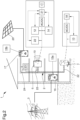
- Other characteristics and advantages of the present invention will become more apparent from the description of a preferred, but not exclusive, embodiment of a system for the management/monitoring of charging means of electric vehicles, illustrated by way of an indicative, yet non-limiting example in the accompanying tables of drawings in which:
-
Figure 1 is a schematic view of the system according to the invention; -
Figure 2 is a schematic view of some details of the system according to the invention. - With particular reference to these figures, reference numeral 1 globally indicates a system for the management/monitoring of charging means of electric vehicles.
- The system 1 for the management/monitoring of charging means comprises at least one
electricity consumption network 2, operationally connected to anelectricity supply network 3, and configured to distribute electricity supplied at least by thesupply network 3. - In the remainder of the following disclosure, the term "consumption network" is used to refer to a utility network, such as a household, business electrical grid, or the like, which is adapted to distribute power to one or more utilities electrically connected/connectable to the grid for the operation thereof. Therefore, the electric consumption of the
consumption network 2 is substantially defined by the sum of the consumption of the electric loads connected to the network itself. - The term supply network, on the other hand, refers to an electricity distribution network, such as e.g. the national distribution network or the like, employed by one or more supplier entities to supply electricity to one or more electricity consumption networks.
- The system 1 additionally comprises charging means 7 of at least one
electric vehicle 8, operationally connected to theconsumption network 2 to charge theelectric vehicle 8. - Specifically, the charging means 7 are configured to charge at least one
electric vehicle 8 with the energy supplied by theconsumption network 2, such as e.g. through thesupply network 3. - In addition, the system 1 comprises management/monitoring means 6 of the charging means 7, operationally connected to the
consumption network 2 and configured to control/monitor thecharging means 7. - Specifically, the system 1 comprises Power-line Communication (PLC) means 12, 13, positioned between the
charging means 7 and the management/monitoring means 6, and configured to allow the communication between the management/monitoring means 6 and the charging means 7 by means of theconsumption network 2. - According to the invention, the
consumption network 2 extends internally/externally to abuilding 4 such as e.g. a dwelling or the like, which defines a plurality of rooms/spaces 5. - In addition, the
consumption network 2 comprises a plurality of connecting points to the network itself, arranged inside different rooms/spaces 5, and to which the management/monitoring means 6, the charging means 7 and the loading means, not shown in the figures, defining at least partly the consumption of the same consumption network, are connected in a removable manner. - Conveniently, the communication between the charging means 7 and the management/monitoring means 6 takes place directly through the
consumption network 2 without the need to establish additional links between them. - In fact, the
consumption network 2 must indispensably connect the charging means 7 to the management/monitoring means 6 so as to supply them with the energy they need for operation. - This expedient makes it possible to arrange the
charging means 7 in any room/space reached by theconsumption network 2, for example, even in a room/space that does not allow wireless communication outside the same room/space, and to arrange the management/monitoring means 6 in a room/space reached by theconsumption network 2 and allowing wireless communication outside the same room/space. - According to the invention, in fact, the charging means 7 are preferably arranged at an
underground car garage 9 of thebuilding 4, while the management/monitoring means 6 are arranged at anupper floor 10 of thebuilding 4, as shown inFigure 1 . - Preferably, the management/monitoring means 6 are totally separate from the
charging means 7. - Advantageously, the management/monitoring means 6 comprise connecting means 19 to command means 11 configured at least to control the management/monitoring means 6.
- According to the invention, the connecting
means 19 are of the type of wireless-type electronic connecting means, such as e.g. a network card or the like, configured to connect to at least one data network, such as e.g. the Internet. Preferably, the command means 11 are of the type of electronic command means configured to connect to the same data network to which the connectingmeans 19 are connected and configured to transmit/receive data/information to/from the management/monitoring means 6. - According to the invention, the command means 11 are of the type of a smart-phone, tablet, PC or the like.
- Preferably, the system 1 comprises command means 11.
- Conveniently, the management/monitoring means 6 are configured to:
- activate/deactivate the charging means 7; and/or
- adjust the charging time of the
electric vehicle 8; and/or - adjust the electricity consumption of the charging means 7; and/or
- time schedule the activation/deactivation of the charging means 7. According to the invention, the charging means 7 are electronically controlled by the command means 11.
- Advantageously, the system 1 comprises metering means 16, 17 configured to meter the consumption of electricity of the
consumption network 2 and to interrupt the supply of the supplied electricity when the consumption thereof by theconsumption network 2 reaches a maximum limit of consumption. - In addition, the system 1 comprises Power-line Communication (PLC) transmission means 14, 15a, 15b, positioned between the metering means 16, 17 and the management/monitoring means 6, and configured to allow the communication between the metering means 16, 17 and the management/monitoring means 6 by means of the
consumption network 2. - In this way, the communication between the management/monitoring means 6 and the metering means 16, 17 takes place directly through the
consumption network 2 without the need to establish additional connections between them. Theconsumption network 2, in fact, must indispensably connect the charging means 7 and the management/monitoring means 6, so that the metering means 16, 17 can account for the consumption of theconsumption network 2. Preferably, the transmission means 14, 15a, 15b allow the metering means 16, 17 to communicate to the management/monitoring means 6 the consumption of electricity of theconsumption network 2. - Conveniently, the system 1 comprises at least one of:
- production means 20 of electricity, operationally connected to the
consumption network 2 and configured to produce electricity; - storage means 24 of electricity, operationally connected to the
consumption network 2 and configured to store at least part of the electricity produced by the production means 20. - Preferably, the system 1 comprises both the production means 20 and the storage means 24.
- In this way, at least part of the energy produced by the production means 20 and stored within the storage means 24.
- Advantageously, the energy stored by the storage means 24 is used/consumed by the
consumption network 2 as needed. - In addition, the production means 20 and the storage means 24 are operationally independently connected to the
consumption network 2. - In this way, the production means 20 and the storage means 24 are operationally connected to each other through the
consumption network 2. - It cannot however be ruled out that the production means 20 and the storage means 24 are operationally connected to each other by dedicated connecting means different from the
consumption network 2. - In addition, further embodiments of the system 1 cannot be ruled out in which at least one of either the production means 20 or the storage means 24 be operationally connected to the consumption network by means of the other one. According to the invention, the production means 20 are of the type of autonomous means of generating electricity, which is consumed by the
consumption network 2 alternatively and/or in combination with the energy supplied by thesupply network 3. - Preferably, the production means 20 are of the type selected from the list comprising: photovoltaic, wind, hydroelectricity.
- According to the invention, the storage means 24 are of the type of one or more electronic electricity storage devices, such as e.g. a battery or the like. Conveniently, the system 1 comprises Power-line Communication (PLC) connecting
means consumption network 2. - In this way, the communication between the management/monitoring means 6 and the storage means 24 takes place directly through the
consumption network 2 without the need to establish additional connections between them. - In fact, the
consumption network 2 must necessarily connect the management/monitoring means 6 to the storage means 24, so that theconsumption network 2 is allowed to use the energy stored by the storage means 24. - Preferably, the connecting
means - Advantageously, the connecting
means device 22, mounted on the management/monitoring means 6, and a second connectingdevice 23 mounted on the storage means 24. - Appropriately, at least one of the connecting
devices consumption network 2 to the other of the connectingdevices - Advantageously, the communication means 12, 13 comprise at least a
first communication device 12, mounted on the management/monitoring means 6, and at least asecond communication device 13 mounted on the charging means 7. - Appropriately, at least one of the
communication devices consumption network 2 to/from theother communication device - Conveniently, the transmission means 14, 15a, 15b comprise at least a
first transmission device 14, mounted on the management/monitoring means 6, and at least asecond transmission device - Appropriately, at least one of the
transmission devices consumption network 2 to/from theother transmission device - In this way, the management/monitoring means 6 are configured to communicate with at least one of the charging means 7, the metering means 16, 17 or the storage means 24, thus enabling the system 1 to manage/adjust the
entire consumption network 2. - In fact, the management/monitoring means 6 comprise computation means 21 positioned between the
consumption network 2 and at least one of thefirst communication device 12, thefirst communication device 14 and the first connectingdevice 22. - Preferably, the computation means 21 are of the type of an electronic data processing device, such as e.g. a microcontroller, CPU or the like. Conveniently, at least one of the communication means 12, 13, the transmission means 14, 15a, 15b or the connecting
means consumption network 2 on a different communication band from at least another of the communication means 12, 13, the transmission means 14, 15a, 15b or the connectingmeans - Preferably, the communication means 12, 13, the transmission means 14, 15a, 15b, and the connecting
means consumption network 2 on different communication bands from each other. - In this way, the communication means 12, 13, the transmission means 14, 15a, 15b and the connecting
means electric vehicle 8 depending on at least one of the energy consumption of theconsumption network 2, the maximum limit of consumption or the electricity stored by the storage means 24. - Conveniently, the management/monitoring means 6 are configured to share on the
consumption network 2, by means of the communication means 12, 13, the transmission means 14, 15a, 15b and the connectingmeans consumption network 2, the maximum limit of consumption with the charging means 7 and the electricity stored by the storage means 24. - In this way, the charging means 7 are configured to reduce their own energy consumption to charge the
electric vehicle 8, by slowing down its charging when the electricity consumption of theconsumption network 2 is close to the maximum limit value. - On the other hand, the charging means 7 are configured to increase their own energy consumption to charge the
electric vehicle 8, by speeding up the charging thereof, when the electricity consumption of theconsumption network 2 is significantly lower than the maximum limit value. - Conveniently, the charging means 7 can draw on the electrical charge stored within the storage means 24 to reduce the energy consumed by the
consumption network 2 and speed up the charging of theelectric vehicle 8. - In this way, the charging means 7 are configured to charge the
electric vehicle 8 more or less quickly depending on the availability of consumption from theconsumption network 2 and/or of the electricity stored by the storage means 24. According to the invention, the adjusting means 18 are of the type of an electronic data processing device, such as e.g. a microcontroller, CPU or the like, configured to control the operation of the charging means 7. - Preferably, the
second communication device 13 is positioned between theconsumption network 2 and the adjusting means 18. In this way, thesecond communication device 13 is configured to communicate at least one of the consumption of theconsumption network 2, the maximum limit and the electricity stored by the storage means 24 to the adjusting means 18. Consequently, the adjusting means 18 are configured to control the charging of theelectric vehicle 8 depending on at least one of the consumption of theconsumption network 2, the maximum limit or the electricity stored by the storage means 24. - Advantageously, the metering means 16, 17 comprise at least one of:
- at least one
consumption metering device 16, positioned between theconsumption network 2 and thesupply network 3, and configured to meter the consumption of the electricity supplied by thesupply network 3; - at least one
production metering device 17, positioned between theconsumption network 2 and the production means 20 of electricity, and configured to meter the consumption of electricity produced by the production means 20. - Additional embodiments of the system 1 cannot however be ruled out, wherein both the production means 20 and the storage means 24 are connected to the
consumption network 2 by means of theproduction metering device 17. According to the invention, the transmission means 14, 15a, 15b comprise at least asecond transmission device 15a mounted on theconsumption metering device 16 and at least one additionalsecond transmission device 15b mounted on theproduction metering device 17. - In this way, the management/monitoring means 6 are configured to detect at least one of the consumption of electricity supplied by the
supply network 3 or the consumption of electricity produced by the production means 20. Preferably, the command means 11 are configured to show at least one of the supplied electricity consumption and the produced electricity consumption to at least one user. - Advantageously, the management/monitoring means 6 are configured to detect at least one characteristic datum of the charging means 7 selected from the list comprising: the charging rate of the
electric vehicle 8, the remaining charging time to complete the charge of theelectric vehicle 8, the energy consumption of the charging means 7, the energy consumption of theconsumption network 2, the electricity output of the production means 20, the electricity stored by the storage means 24, the input of electricity into theconsumption network 2 and/or into thesupply network 3 by theelectric vehicle 8 and/or by the production means 20 and/or by the storage means 24. - According to the invention, the command means 11 are configured to show at least one of the characteristic data to at least one user.
- It has in practice been ascertained that the described invention achieves the intended objects.
- In particular, the fact is emphasized that the PLC communication means enable the management/monitoring means to communicate with the charging means directly on the consumption line, without the need to install a physical link specifically made for this purpose and significantly facilitating the communication with the charging means.
- Advantageously, the PLC communication and transmission means enable the management/monitoring means 6 to manage/monitor the charging means of electric vehicles according to the status of the power grid to which the charging means themselves are connected.
- In addition, the PLC communication and transmission means enable the management/monitoring of both the charging means and the power grid to which the charging means are connected.
Claims (12)
- System (1) for the management/monitoring of charging means of electric vehicle, comprising:- at least one electricity consumption network (2), operationally connected to an electricity supply network (3), and configured to distribute electricity supplied at least by the supply network (3);- charging means (7) of at least one electric vehicle (8), operationally connected to said consumption network (2) to charge the electric vehicle (8);- management/monitoring means (6) of said charging means (7), operationally connected to said consumption network (2) and configured to control/monitor said charging means (7);characterized by the fact that it comprises power-line communication (PLC) means (12, 13) positioned between said charging means (7) and said management/monitoring means (6), and configured to allow the communication between said management/monitoring means (6) and said charging means (7) by means of said consumption network (2).
- System (1) according to claim 1, characterized by the fact that said management/monitoring means (6) are configured to:- activate/deactivate said charging means (7); and/or- adjust the charging time of the electric vehicle (8); and/or- adjust the electricity consumption of said charging means (7); and/or- schedule the activation/deactivation of said charging means (7).
- System (1) according to one or more of the preceding claims, characterized by the fact that said management/monitoring means (6) comprise connecting means (19) to command means (11) configured to control said management/monitoring means (6).
- System (1) according to one or more of the preceding claims, characterized by the fact that it comprises:- metering means (16, 17) configured to meter the consumption of electricity of said consumption network (2) and to interrupt the supply of said supplied electricity when the consumption thereof by said consumption network (2) reaches a maximum limit of consumption;- power-line communication (PLC) transmission means (14, 15a, 15b), positioned between said metering means (16, 17) and said management/monitoring means (6), and configured to allow the communication between said metering means (16, 17) and said management/monitoring means (6) by means of said consumption network (2).
- System (1) according to one or more of the preceding claims, characterized by the fact that it comprises at least one of:- production means (20) of electricity, operationally connected to said consumption network (2) and configured to produce electricity;- storage means (24) of electricity, operationally connected to said consumption network (2) and configured to store at least part of the electricity produced by said production means (20).
- System (1) according to one or more of the preceding claims, characterized by the fact that it comprises power-line communication (PLC) connecting means (22, 23), positioned between said management/monitoring means (6) and said storage means (24), and configured to allow the communication between said management/monitoring means (6) and said storage means (24) by means of said consumption network (2).
- System (1) according to one or more of the preceding claims, characterized by the fact that said metering means (16, 17) comprise at least one of:- at least one consumption metering device (16), positioned between said consumption network (2) and the supply network (3), and configured to meter the consumption of the electricity supplied by the supply network (3);- at least one production metering device (17), positioned between said consumption network (2) and production means (20) of electricity, and configured to meter the consumption of the electricity produced by the production means (20).
- System (1) according to one or more of the preceding claims, characterized by the fact that said charging means (7) comprise adjusting means (18) configured to increase/reduce the electricity consumed by the same charging means to charge the electric vehicle (8) depending on at least one of said energy consumption of said consumption network (2), said maximum limit of consumption or said electricity stored by said storage means (24).
- System (1) according to one or more of the preceding claims, characterized by the fact that at least one of said communication means (12, 13), said transmission means (14, 15a, 15b) or said connecting means (22, 23) are configured to communicate on said consumption network (2) on a different communication band from at least another of said communication means (12, 13), said transmission means (14, 15a, 15b) or said connecting means (22, 23).
- System (1) according to one or more of the preceding claims, characterized by the fact that:- said communication means (12, 13) comprise at least a first communication device (12), mounted on said management/monitoring means (6), and at least a second communication device (13) mounted on said charging means (7), at least one of said communication devices (12, 13) being configured to transmit/receive data/information by means of said consumption network (2) to/from the other communication device (12, 13); and/or- said transmission means (14, 15a, 15b) comprise at least a first transmission device (14), mounted on said management/monitoring means (6), and at least a second transmission device (15a, 15b) mounted on said metering means (16, 17), at least one of said transmission devices (14, 15a, 15b) being configured to transmit/receive data/information by means of said consumption network (2) to/from the other transmission device (14, 15a, 15b); and/or- said connecting means (22, 23) comprise at least a first connecting device (22), mounted on said management/monitoring means (6), and at least a second connecting device (23) mounted on said storage means (24), at least one of said connecting devices (22, 23) being configured to transmit/receive data/information by means of said consumption network (2) to the other of said connecting devices (22, 23).
- System (1) according to one or more of the preceding claims, characterized by the fact that said management/monitoring means (6) are configured to detect at least one characteristic datum of at least one of said charging means (7), said production means (20), said storage means (24) and said metering means (16, 17), selected from the list comprising: the charging rate of the electric vehicle (8), the remaining charging time to complete the charge of the electric vehicle (8), the energy consumption of said charging means (7), the energy consumption of said consumption network (2), the electricity output of said production means (20), the electricity stored by said storage means (24), the input of electricity into said consumption network (2) and/or into said supply network (3) by the electric vehicle (8) and/or by said production means (20) and/or by said storage means (24).
- System (1) according to one or more of the preceding claims, characterized by the fact that said consumption network (2) extends internally/externally to a building (4) defining a plurality of rooms/spaces (5), said consumption network (2) comprising a plurality of connecting points (22) to the network itself, arranged inside different rooms/spaces (5) and to which are connectable in a removable manner said management/monitoring means (6), said charging means (7) and loading means defining, at least partly, the consumption of the same consumption network.
Applications Claiming Priority (1)
| Application Number | Priority Date | Filing Date | Title |
|---|---|---|---|
| IT102021000020813A IT202100020813A1 (en) | 2021-08-02 | 2021-08-02 | MANAGEMENT/MONITORING SYSTEM FOR RECHARGING MEANS OF ELECTRIC VEHICLES |
Publications (3)
| Publication Number | Publication Date |
|---|---|
| EP4129747A1 true EP4129747A1 (en) | 2023-02-08 |
| EP4129747B1 EP4129747B1 (en) | 2025-09-03 |
| EP4129747C0 EP4129747C0 (en) | 2025-09-03 |
Family
ID=78463732
Family Applications (1)
| Application Number | Title | Priority Date | Filing Date |
|---|---|---|---|
| EP22187196.5A Active EP4129747B1 (en) | 2021-08-02 | 2022-07-27 | System for the management/monitoring of charging means of electric vehicle |
Country Status (2)
| Country | Link |
|---|---|
| EP (1) | EP4129747B1 (en) |
| IT (1) | IT202100020813A1 (en) |
Cited By (2)
| Publication number | Priority date | Publication date | Assignee | Title |
|---|---|---|---|---|
| FR3153293A1 (en) * | 2023-09-25 | 2025-03-28 | Michaud | Installation for charging electric vehicles |
| WO2025094015A1 (en) * | 2023-10-31 | 2025-05-08 | Ather Energy Limited | System and method for optimizing electrical load in multi-level structures for charging electric vehicles |
Citations (6)
| Publication number | Priority date | Publication date | Assignee | Title |
|---|---|---|---|---|
| WO2010042550A2 (en) * | 2008-10-07 | 2010-04-15 | Johnson Controls Technology Company | Efficient usage, storage, and sharing of energy in buildings, vehicles, and equipment |
| US20100145837A1 (en) * | 2008-12-05 | 2010-06-10 | Lava Four, Llc | Network for authentication, authorization, and accounting of recharging processes for vehicles equipped with electrically powered propulsion systems |
| US20120323386A1 (en) * | 2011-06-14 | 2012-12-20 | Denso Corporation | Electric power supply system |
| WO2013065380A2 (en) * | 2011-10-31 | 2013-05-10 | Toyota Jidosha Kabushiki Kaisha | Vehicle with an electric storage section capable of discharging (supplying) an electric power to an external electric load, discharge system including the vehicle and a power cable, method for discharging the electric storage section, and equipment external to the vehicle used in the discharge system |
| US8686687B2 (en) * | 2008-12-15 | 2014-04-01 | Comverge, Inc. | Method and system for co-operative charging of electric vehicles |
| US20210170903A1 (en) * | 2019-12-09 | 2021-06-10 | Toyota Jidosha Kabushiki Kaisha | Power management system and server |
-
2021
- 2021-08-02 IT IT102021000020813A patent/IT202100020813A1/en unknown
-
2022
- 2022-07-27 EP EP22187196.5A patent/EP4129747B1/en active Active
Patent Citations (6)
| Publication number | Priority date | Publication date | Assignee | Title |
|---|---|---|---|---|
| WO2010042550A2 (en) * | 2008-10-07 | 2010-04-15 | Johnson Controls Technology Company | Efficient usage, storage, and sharing of energy in buildings, vehicles, and equipment |
| US20100145837A1 (en) * | 2008-12-05 | 2010-06-10 | Lava Four, Llc | Network for authentication, authorization, and accounting of recharging processes for vehicles equipped with electrically powered propulsion systems |
| US8686687B2 (en) * | 2008-12-15 | 2014-04-01 | Comverge, Inc. | Method and system for co-operative charging of electric vehicles |
| US20120323386A1 (en) * | 2011-06-14 | 2012-12-20 | Denso Corporation | Electric power supply system |
| WO2013065380A2 (en) * | 2011-10-31 | 2013-05-10 | Toyota Jidosha Kabushiki Kaisha | Vehicle with an electric storage section capable of discharging (supplying) an electric power to an external electric load, discharge system including the vehicle and a power cable, method for discharging the electric storage section, and equipment external to the vehicle used in the discharge system |
| US20210170903A1 (en) * | 2019-12-09 | 2021-06-10 | Toyota Jidosha Kabushiki Kaisha | Power management system and server |
Cited By (2)
| Publication number | Priority date | Publication date | Assignee | Title |
|---|---|---|---|---|
| FR3153293A1 (en) * | 2023-09-25 | 2025-03-28 | Michaud | Installation for charging electric vehicles |
| WO2025094015A1 (en) * | 2023-10-31 | 2025-05-08 | Ather Energy Limited | System and method for optimizing electrical load in multi-level structures for charging electric vehicles |
Also Published As
| Publication number | Publication date |
|---|---|
| EP4129747B1 (en) | 2025-09-03 |
| IT202100020813A1 (en) | 2023-02-02 |
| EP4129747C0 (en) | 2025-09-03 |
Similar Documents
| Publication | Publication Date | Title |
|---|---|---|
| LeMay et al. | An integrated architecture for demand response communications and control | |
| US8515383B2 (en) | Utility powered communications gateway | |
| CN101853017B (en) | Energy management system and method | |
| US8868248B2 (en) | Smart control device | |
| EP3002848B1 (en) | Demand-side grid-level load balancing aggregation system | |
| US20160126783A1 (en) | Smart home power system | |
| US10962941B2 (en) | Controlling a distributed generation management system | |
| US12611955B1 (en) | Smart load management apparatus and system for electric vehicle charging | |
| CN103148563B (en) | A kind of air-conditioner control system and control method | |
| EP4129747A1 (en) | System for the management/monitoring of charging means of electric vehicle | |
| JP2014504145A (en) | Energy interface system | |
| US20120059529A1 (en) | Apparatus and method for controlling power | |
| US9417673B2 (en) | Method, apparatus and graphical user interface for controlling power | |
| WO2016002347A1 (en) | Power control system, method, and power control device | |
| EP3183706B1 (en) | System and method of controlling supply of electrical power | |
| JP2022513238A (en) | Energy distribution system | |
| CN102394512A (en) | Power supply and power utilization management system | |
| US20120059531A1 (en) | Apparatus and method for controlling power | |
| KR101084156B1 (en) | Lighting and air conditioning system | |
| EP2856597A2 (en) | Unit for controlling and managing for devices of the type of battery charger | |
| WO2012156712A2 (en) | Optimising use of energy | |
| JP2014112989A (en) | Power metering information relay device, method for determining relay device installation location, and method for power metering information communication | |
| WO2016029942A1 (en) | Method to control a flow of energy between a grid and a local system | |
| KR101625689B1 (en) | Network system | |
| SE1100591A1 (en) | Procedures and systems to meet the needs of residential buildings |
Legal Events
| Date | Code | Title | Description |
|---|---|---|---|
| PUAI | Public reference made under article 153(3) epc to a published international application that has entered the european phase |
Free format text: ORIGINAL CODE: 0009012 |
|
| STAA | Information on the status of an ep patent application or granted ep patent |
Free format text: STATUS: THE APPLICATION HAS BEEN PUBLISHED |
|
| AK | Designated contracting states |
Kind code of ref document: A1 Designated state(s): AL AT BE BG CH CY CZ DE DK EE ES FI FR GB GR HR HU IE IS IT LI LT LU LV MC MK MT NL NO PL PT RO RS SE SI SK SM TR |
|
| STAA | Information on the status of an ep patent application or granted ep patent |
Free format text: STATUS: REQUEST FOR EXAMINATION WAS MADE |
|
| 17P | Request for examination filed |
Effective date: 20230807 |
|
| RBV | Designated contracting states (corrected) |
Designated state(s): AL AT BE BG CH CY CZ DE DK EE ES FI FR GB GR HR HU IE IS IT LI LT LU LV MC MK MT NL NO PL PT RO RS SE SI SK SM TR |
|
| STAA | Information on the status of an ep patent application or granted ep patent |
Free format text: STATUS: EXAMINATION IS IN PROGRESS |
|
| 17Q | First examination report despatched |
Effective date: 20240326 |
|
| RIC1 | Information provided on ipc code assigned before grant |
Ipc: G06Q 50/40 20240101ALI20250217BHEP Ipc: G06Q 10/063 20230101ALI20250217BHEP Ipc: H02J 7/34 20060101ALI20250217BHEP Ipc: G07C 5/00 20060101ALI20250217BHEP Ipc: G06Q 50/06 20120101ALI20250217BHEP Ipc: B60L 55/00 20190101ALI20250217BHEP Ipc: H02J 13/00 20060101ALI20250217BHEP Ipc: H02J 7/00 20060101ALI20250217BHEP Ipc: H02J 3/38 20060101ALI20250217BHEP Ipc: H02J 3/32 20060101ALI20250217BHEP Ipc: B60L 53/51 20190101ALI20250217BHEP Ipc: B60L 53/66 20190101ALI20250217BHEP Ipc: B60L 53/63 20190101AFI20250217BHEP |
|
| GRAP | Despatch of communication of intention to grant a patent |
Free format text: ORIGINAL CODE: EPIDOSNIGR1 |
|
| STAA | Information on the status of an ep patent application or granted ep patent |
Free format text: STATUS: GRANT OF PATENT IS INTENDED |
|
| INTG | Intention to grant announced |
Effective date: 20250402 |
|
| GRAS | Grant fee paid |
Free format text: ORIGINAL CODE: EPIDOSNIGR3 |
|
| GRAA | (expected) grant |
Free format text: ORIGINAL CODE: 0009210 |
|
| STAA | Information on the status of an ep patent application or granted ep patent |
Free format text: STATUS: THE PATENT HAS BEEN GRANTED |
|
| AK | Designated contracting states |
Kind code of ref document: B1 Designated state(s): AL AT BE BG CH CY CZ DE DK EE ES FI FR GB GR HR HU IE IS IT LI LT LU LV MC MK MT NL NO PL PT RO RS SE SI SK SM TR |
|
| REG | Reference to a national code |
Ref country code: CH Ref legal event code: EP |
|
| REG | Reference to a national code |
Ref country code: DE Ref legal event code: R096 Ref document number: 602022020618 Country of ref document: DE |
|
| REG | Reference to a national code |
Ref country code: IE Ref legal event code: FG4D |
|
| U01 | Request for unitary effect filed |
Effective date: 20250929 |
|
| U07 | Unitary effect registered |
Designated state(s): AT BE BG DE DK EE FI FR IT LT LU LV MT NL PT RO SE SI Effective date: 20251009 |
|
| PG25 | Lapsed in a contracting state [announced via postgrant information from national office to epo] |
Ref country code: NO Free format text: LAPSE BECAUSE OF FAILURE TO SUBMIT A TRANSLATION OF THE DESCRIPTION OR TO PAY THE FEE WITHIN THE PRESCRIBED TIME-LIMIT Effective date: 20251203 |
|
| PG25 | Lapsed in a contracting state [announced via postgrant information from national office to epo] |
Ref country code: HR Free format text: LAPSE BECAUSE OF FAILURE TO SUBMIT A TRANSLATION OF THE DESCRIPTION OR TO PAY THE FEE WITHIN THE PRESCRIBED TIME-LIMIT Effective date: 20250903 |
|
| PG25 | Lapsed in a contracting state [announced via postgrant information from national office to epo] |
Ref country code: GR Free format text: LAPSE BECAUSE OF FAILURE TO SUBMIT A TRANSLATION OF THE DESCRIPTION OR TO PAY THE FEE WITHIN THE PRESCRIBED TIME-LIMIT Effective date: 20251204 |
|
| PG25 | Lapsed in a contracting state [announced via postgrant information from national office to epo] |
Ref country code: PL Free format text: LAPSE BECAUSE OF FAILURE TO SUBMIT A TRANSLATION OF THE DESCRIPTION OR TO PAY THE FEE WITHIN THE PRESCRIBED TIME-LIMIT Effective date: 20250903 |
|
| PG25 | Lapsed in a contracting state [announced via postgrant information from national office to epo] |
Ref country code: RS Free format text: LAPSE BECAUSE OF FAILURE TO SUBMIT A TRANSLATION OF THE DESCRIPTION OR TO PAY THE FEE WITHIN THE PRESCRIBED TIME-LIMIT Effective date: 20251203 |
|
| PG25 | Lapsed in a contracting state [announced via postgrant information from national office to epo] |
Ref country code: ES Free format text: LAPSE BECAUSE OF FAILURE TO SUBMIT A TRANSLATION OF THE DESCRIPTION OR TO PAY THE FEE WITHIN THE PRESCRIBED TIME-LIMIT Effective date: 20250903 |
|
| PG25 | Lapsed in a contracting state [announced via postgrant information from national office to epo] |
Ref country code: SM Free format text: LAPSE BECAUSE OF FAILURE TO SUBMIT A TRANSLATION OF THE DESCRIPTION OR TO PAY THE FEE WITHIN THE PRESCRIBED TIME-LIMIT Effective date: 20250903 |
|
| PG25 | Lapsed in a contracting state [announced via postgrant information from national office to epo] |
Ref country code: IS Free format text: LAPSE BECAUSE OF FAILURE TO SUBMIT A TRANSLATION OF THE DESCRIPTION OR TO PAY THE FEE WITHIN THE PRESCRIBED TIME-LIMIT Effective date: 20260103 |
|
| PG25 | Lapsed in a contracting state [announced via postgrant information from national office to epo] |
Ref country code: CZ Free format text: LAPSE BECAUSE OF FAILURE TO SUBMIT A TRANSLATION OF THE DESCRIPTION OR TO PAY THE FEE WITHIN THE PRESCRIBED TIME-LIMIT Effective date: 20250903 |
|
| PG25 | Lapsed in a contracting state [announced via postgrant information from national office to epo] |
Ref country code: SK Free format text: LAPSE BECAUSE OF FAILURE TO SUBMIT A TRANSLATION OF THE DESCRIPTION OR TO PAY THE FEE WITHIN THE PRESCRIBED TIME-LIMIT Effective date: 20250903 |