EP4129707A1 - Printed matter, booklet, combination of light source and printed matter, and method for determining authenticity of printed matter - Google Patents
Printed matter, booklet, combination of light source and printed matter, and method for determining authenticity of printed matter Download PDFInfo
- Publication number
- EP4129707A1 EP4129707A1 EP21781754.3A EP21781754A EP4129707A1 EP 4129707 A1 EP4129707 A1 EP 4129707A1 EP 21781754 A EP21781754 A EP 21781754A EP 4129707 A1 EP4129707 A1 EP 4129707A1
- Authority
- EP
- European Patent Office
- Prior art keywords
- colored picture
- printed matter
- layer
- picture layer
- luminous
- Prior art date
- Legal status (The legal status is an assumption and is not a legal conclusion. Google has not performed a legal analysis and makes no representation as to the accuracy of the status listed.)
- Pending
Links
Images







Classifications
-
- B—PERFORMING OPERATIONS; TRANSPORTING
- B42—BOOKBINDING; ALBUMS; FILES; SPECIAL PRINTED MATTER
- B42D—BOOKS; BOOK COVERS; LOOSE LEAVES; PRINTED MATTER CHARACTERISED BY IDENTIFICATION OR SECURITY FEATURES; PRINTED MATTER OF SPECIAL FORMAT OR STYLE NOT OTHERWISE PROVIDED FOR; DEVICES FOR USE THEREWITH AND NOT OTHERWISE PROVIDED FOR; MOVABLE-STRIP WRITING OR READING APPARATUS
- B42D25/00—Information-bearing cards or sheet-like structures characterised by identification or security features; Manufacture thereof
- B42D25/30—Identification or security features, e.g. for preventing forgery
- B42D25/36—Identification or security features, e.g. for preventing forgery comprising special materials
- B42D25/378—Special inks
-
- B—PERFORMING OPERATIONS; TRANSPORTING
- B42—BOOKBINDING; ALBUMS; FILES; SPECIAL PRINTED MATTER
- B42D—BOOKS; BOOK COVERS; LOOSE LEAVES; PRINTED MATTER CHARACTERISED BY IDENTIFICATION OR SECURITY FEATURES; PRINTED MATTER OF SPECIAL FORMAT OR STYLE NOT OTHERWISE PROVIDED FOR; DEVICES FOR USE THEREWITH AND NOT OTHERWISE PROVIDED FOR; MOVABLE-STRIP WRITING OR READING APPARATUS
- B42D25/00—Information-bearing cards or sheet-like structures characterised by identification or security features; Manufacture thereof
- B42D25/30—Identification or security features, e.g. for preventing forgery
- B42D25/36—Identification or security features, e.g. for preventing forgery comprising special materials
- B42D25/378—Special inks
- B42D25/387—Special inks absorbing or reflecting ultraviolet light
-
- G—PHYSICS
- G07—CHECKING-DEVICES
- G07D—HANDLING OF COINS OR VALUABLE PAPERS, e.g. TESTING, SORTING BY DENOMINATIONS, COUNTING, DISPENSING, CHANGING OR DEPOSITING
- G07D7/00—Testing specially adapted to determine the identity or genuineness of valuable papers or for segregating those which are unacceptable, e.g. banknotes that are alien to a currency
- G07D7/06—Testing specially adapted to determine the identity or genuineness of valuable papers or for segregating those which are unacceptable, e.g. banknotes that are alien to a currency using wave or particle radiation
- G07D7/12—Visible light, infrared or ultraviolet radiation
- G07D7/1205—Testing spectral properties
-
- G—PHYSICS
- G07—CHECKING-DEVICES
- G07D—HANDLING OF COINS OR VALUABLE PAPERS, e.g. TESTING, SORTING BY DENOMINATIONS, COUNTING, DISPENSING, CHANGING OR DEPOSITING
- G07D7/00—Testing specially adapted to determine the identity or genuineness of valuable papers or for segregating those which are unacceptable, e.g. banknotes that are alien to a currency
- G07D7/20—Testing patterns thereon
- G07D7/202—Testing patterns thereon using pattern matching
- G07D7/207—Matching patterns that are created by the interaction of two or more layers, e.g. moiré patterns
Definitions
- the present disclosure relates to a printed matter including a substrate and a luminous printed layer containing a luminous body and a combination of a light source and a printed matter.
- a printed matter, such as securities, that requires security includes a substrate and a luminous printed layer provided on the substrate through the use of a luminous body, and has a structure that prevents forgery or alteration or discriminates between a counterfeit product and a genuine product. Further, in general, a colored picture layer may be formed on the substrate separately from the luminous printed layer.
- a method for determining the authenticity of a printed matter given such a luminous printed layer a method by which a printed matter is irradiated with electromagnetic waves or radiation such as excitation light containing energy capable of exciting a luminous body and sensing is done with a read device or machine such as a sensor is commonly used.
- a luminous body is a visible luminous body
- a method for authenticating the emission of light with a human eye by using a simple light source such as a black light as an excitation source.
- a simple light source such as a black light as an excitation source.
- the present disclosure was made in view of visually identifying the emission of light through the use of a commonly available light source such as a black light, and has as an object to provide a printed matter that can be visually recognized with changes easily and surely made in shape, size, number, or shading of a picture or pictures of a colored picture layer simply by moving a light source closer to and away from the printed matter and a combination of a light source and a printed matter.
- a commonly available light source such as a black light
- the present disclosure is directed to a printed matter that is irradiated with excitation light from a light source, the printed matter including: a substrate; a luminous printed layer, provided on the substrate, that contains a luminous body; and a colored picture layer, provided on the substrate, that contains a pigment or a dye, wherein the luminous printed layer and the colored picture layer overlap each other, the colored picture layer has a body region and a peripheral edge region, and a color density of the colored picture layer of the peripheral edge region gradually decreases toward a peripheral edge of the colored picture layer.
- the present disclosure is directed to a printed matter that is irradiated with excitation light from a light source, the printed matter including: a substrate containing a luminous body; and a colored picture layer, provided on the substrate, that contains a pigment or a dye, wherein the colored picture layer has a body region and a peripheral edge region, and a color density of the colored picture layer of the peripheral edge region gradually decreases toward a peripheral edge of the colored picture layer.
- the present disclosure is directed to the printed matter, wherein the colored picture layer is formed by halftone-dot printing, and in the peripheral edge region, a halftone-dot density of the colored picture layer gradually decreases toward the peripheral edge.
- the present disclosure is directed to the printed matter, wherein the colored picture layer includes a plurality of minute printing elements or fine printing elements, and in the peripheral edge region, a density of the minute printing elements or fine printing elements of the colored picture layer gradually decreases toward the peripheral edge.
- the present disclosure is directed to the printed matter, wherein the colored picture layer forms a letter or a figure, and the peripheral edge region is formed along an outer edge of the letter or the figure.
- the present disclosure is directed to the printed matter, wherein the colored picture layer forms a letter or a figure, and the peripheral edge region is formed along an inner edge of the letter or the figure.
- the present disclosure is directed to a printed matter that is irradiated with excitation light from a light source, the printed matter including: a substrate; a luminous printed layer, provided on the substrate, that contains a luminous body; and a colored picture layer, provided on the substrate, that contains a pigment or a dye, wherein the luminous printed layer and the colored picture layer overlap each other, the colored picture layer includes a series of a plurality of colored picture portions placed one after another, and a color density of the plurality of colored picture portions continuously gradually decreases from a colored picture portion on one side toward a colored picture portion on the other side.
- the present disclosure is directed to a printed matter that is irradiated with excitation light from a light source, the printed matter including: a substrate containing a luminous body; and a colored picture layer, provided on the substrate, that contains a pigment or a dye, wherein the colored picture layer includes a series of a plurality of colored picture portions placed one after another, and a color density of the plurality of colored picture portions continuously gradually decreases from a colored picture portion on one side toward a picture portion on the other side.
- the present disclosure is directed to a printed matter that is irradiated with excitation light from a light source, the printed matter including: a substrate; a luminous printed layer, provided on the substrate, that contains a luminous body; and a colored picture layer, provided on the substrate, that contains a pigment or a dye, wherein the luminous printed layer and the colored picture layer overlap each other, and the colored picture layer forms a color pattern including a plurality of minute printing elements or fine printing elements having different shapes.
- the present disclosure is directed to a printed matter that is irradiated with excitation light from a light source, the printed matter including: a substrate containing a luminous body; and a colored picture layer, provided on the substrate, that contains a pigment or a dye, wherein the colored picture layer forms a color pattern including a plurality of minute printing elements or fine printing elements having different shapes.
- the present disclosure is directed to the printed matter, further comprising an overcoat layer, provided on the substrate, that covers at least the colored picture layer.
- a booklet includes the printed matter described above.
- a combination of a light source and a printed matter includes the printed matter described above and the light source that emits the excitation light.
- a method for determining authenticity of a printed matter with the combination of a light source and a printed matter described above includes the steps of irradiating a surface of the printed matter with the excitation light from the light source and determining the authenticity of the printed matter by visually recognizing the printed matter with changes made in shape, size, number, or shading of an outwardly-appearing picture or pictures of the colored picture layer by moving the light source closer to and away from the printed matter.
- the present disclosure makes it possible to visually recognize the shape, size, number, or shading of a picture or pictures of the colored picture layer with changes easily and surely made simply by moving the light source closer to and away from the printed matter.
- the printed matter 10 can be used as a security material for a booklet or a card.
- the printed matter 10 per se may be a booklet such as a passport, a data page of a passport, a gift certificate, or a bill, or may be contained in a layer of an ID, a ticket, or a card (contact or non-contact integrated-circuit (IC) card).
- the printed matter 10 is irradiated, for example, with ultraviolet light (UV light) with a center wavelength of 365 nm from a light source 25 such as a UV discharge tube constituting a black light.
- the UV light emitted by the light source functions as excitation light that excites a luminous body of the after-mentioned luminous printed layer 20 to emit light.
- the light source 25 may be a UV-LED light source.
- the present embodiment illustrates a case where the printed matter 10 constitutes a card such as a certification card.
- a printed matter 10 constituting a certification card includes a substrate 11 made of synthetic resin, an ordinary printed layer 12 provided on the substrate 11 and composed of letters, numbers, or other characters, a colored picture layer 30 provided on the substrate 11, a luminous printed layer 20 provided so as to entirely cover the colored picture layer 30, and an overcoat layer 13 covering the ordinary printed layer 12, the colored picture layer 30, and the luminous printed layer 20, which are provided on the substrate 11.
- Fig. 2 is a plan view showing the printed matter 10
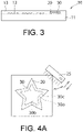
- Fig. 3 is a side view showing the printed matter 10.
- the substrate 11 is made of polycarbonate (PC), polyethylene terephthalate (PET), amorphous polyester (PET-G), polyvinyl chloride (PVC), or polypropylene (PP).
- the substrate 11 may be a paper substrate.
- the overcoat layer 13 is made of polycarbonate (PC), polyethylene terephthalate (PET), amorphous polyester (PET-G), polyvinyl chloride (PVC), or polypropylene (PP).
- PC polycarbonate
- PET polyethylene terephthalate
- PET-G amorphous polyester
- PVC polyvinyl chloride
- PP polypropylene
- the ordinary printed layer 12 and the colored picture layer 30 are formed with normal print ink containing a common pigment or dye.
- a printing method a printing method, such as offset printing, silk screen printing, or inkjet printing, that allows printing on the substrate is selected as appropriate.
- the hues of the ordinary printed layer 12 and the colored picture layer 30 under visible light are chromatic colors, and do not have transparency. Any color or ink that can be printed by the printing method may be used. It should be noted that the colored picture layer 30 will be further described later.
- the luminous printed layer 20 is obtained by doing printing so as to entirely cover the colored picture layer 30 with a luminous body that emits light upon irradiation with excitation light.
- the hue of the luminous printed layer 20 may be either colorless or colorless and transparent, may be the body color of a pigment, or may be the chromatic color of color pigments mixed or a chromatic color having transparency.
- the luminous printed layer 20 of the printed matter needs to be without incongruity in color and appearance with the hue of the colored picture layer 30.
- the tint of color pigments mixed is deep, the luminous color of the luminous body is absorbed, with the result that it becomes hard to visually recognize a change in the luminous color; therefore, it is preferable that the chromatic color of a color pigment be light. Note, however, that since there are many types of ink or color pigment available in the world and there are more than several hundred types of ink and color pigment, a preferred form or composition ratio changes accordingly depending on the type of ink or pigment.
- a usable example of a luminous body that constitutes the luminous body of the luminous printed layer 20 is a blue luminous body (such as BaMgAl 10 O 17 :Eu), a green luminous body (such as SrAl 2 0 4 :Eu,Dy, Sr 4 Al 14 0 25 :Eu,Dy, ZnO, Zn 2 GeO 4 :Mn), a red luminous body (such as YVO 4 :Bi,Eu, Y 2 O 2 S:Eu), or a while luminous body (such as a blue, green, and red mixed luminous body "Y 2 O 2 S:Eu, Zn 2 GeO 4 :Mn, BaMgAl 10 O 17 :Eu").
- a blue luminous body such as BaMgAl 10 O 17 :Eu
- a green luminous body such as SrAl 2 0 4 :Eu,Dy, Sr 4 Al 14 0 25 :Eu,D
- the luminous printed layer 20 is formed by printing with luminous body ink containing the aforementioned luminous body.
- a printing method such as offset printing, silk screen printing, or inkjet printing, that allows printing on the substrate is selected as appropriate.
- a publicly-known printing method may be used as a method for applying the luminous body ink onto the colored picture layer 30 of the substrate 11, for example, by printing or coating.
- a method for example, for printing such as intaglio printing, anastatic printing, offset printing, screen printing, gravure printing, flexo printing, and inkjet printing or coating.
- the luminous body ink may be applied onto the colored picture layer 30 of the substrate 11 by a combination of these printing methods.
- the luminous body ink further contains, for example, aqueous varnish, solvent varnish, oxidative polymerizable varnish, radiation curable varnish, radiation curable and oxidative polymerizable hybrid varnish in addition to the luminous body.
- the luminous body ink contains various types of varnish as mentioned earlier, and has its viscosity or other properties adjusted so that the various types of varnish may be mixed up.
- the blending ratio of the luminous body be higher than or equal to 1 mass%, more preferably higher than or equal to 3 mass%, or even more preferably higher than or equal to 5 mass%, although the blending ratio varies depending on how the luminous printed layer 20 is formed.
- the blending ratio be lower than or equal to 60 mass% , more preferably lower than or equal to 50 mass%, or even more preferably lower than or equal to 40 mass%.
- the luminous body ink is produced by sufficiently dispersing the luminous body in the varnish with a three-roll mill, a ball mill, a bead mill, or other mills. It should be noted that a kneading method and an appropriate viscosity are selected as appropriate depending on how the luminous body ink is applied.
- the luminous body ink may be formed into ink or paste by mixing another color material or functional material to such an extent as not to prevent emission of light, and is applied onto the colored picture layer 30 provided in advance onto the substrate 11. That is, the ordinary printed layer 12 and the colored picture layer 30, which are formed in advance with normal print ink and form a printed picture, are provided on the substrate 11, and the luminous body ink is applied onto the colored picture layer 30 of the substrate 11 to form the luminous printed layer 20.
- the colored picture layer 30 provided on the substrate 11 is further described with reference to Fig. 1 .
- the colored picture layer 30 is provided on the substrate 11 through the use of print ink, and on the colored picture layer 30, the luminous printed layer 20 is provided through the use of luminous body ink so as to entirely cover the colored picture layer 30.
- the colored picture layer 30 has a star shape having a peripheral edge region 30a located at a peripheral edge and a region other than the peripheral edge region 30a, specifically a body region 30b located in the center.
- the colored picture layer 30 of the peripheral edge region 30a has its color density gradually decreasing toward a peripheral edge 30c of the colored picture layer 30, and the colored picture layer 30 is disposed so that its density is in a state of gradation in the peripheral edge region 30a.
- the luminous printed layer 20 too has a star shape that is similar to that of the colored picture layer 30.
- the body region 30a has a halftone-dot density of, for example, 100%.
- the peripheral edge region 30a has its halftone-dot density gradually decreasing from the body region 30b toward the peripheral edge 30c, and the colored picture layer 30 is disposed so that its density is in a state of gradation in the peripheral edge region 30a.
- the peripheral edge region 30a of the colored picture layer 30 has its halftone-dot density decreasing, for example, from 100% to 0% from the body region 30b toward the peripheral edge 30c.
- the peripheral edge region 30a of the colored picture layer 30 has its halftone-dot density decreasing, for example, from 100% to 0% from the body region 30b toward the peripheral edge 30c, and in this case, the halftone-dot density may vary from 100%, 99%, 98%, and 97% to 5%, 4%, 3%, 2%, 1%, and 0% in decrements of 1%.
- the halftone-dot density may vary in decrements of 0.1% or 0.001%, and there is no need to place upper or lower limits on the decrements.
- the colored picture layer 30 may be printed not by halftone-dot printing but by using minute printing elements such as micro letters and minute symbols, letters, and figures or fine printing elements such as parallel lines, wavy lines, or dashed lines, and in this case, the body region 30b of the colored picture layer 30 has its minute printing element or fine printing element density of, for example, 100%. Further, the peripheral edge region 30a has its minute printing element or fine printing element density gradually decreasing from the body region 30b toward the peripheral edge 30c, and the colored picture layer 30 is disposed so that its density is in a state of gradation in the peripheral edge region 30a.
- minute printing elements such as micro letters and minute symbols, letters, and figures or fine printing elements such as parallel lines, wavy lines, or dashed lines
- the body region 30b of the colored picture layer 30 has its minute printing element or fine printing element density of, for example, 100%.
- the peripheral edge region 30a has its minute printing element or fine printing element density gradually decreasing from the body region 30b toward the peripheral edge 30c, and the colored picture
- the peripheral edge region 30a of the colored picture layer 30 has its minute printing element or fine printing element density decreasing, for example, from 100% to 0% from the body region 30b toward the peripheral edge 30c. This causes the peripheral edge region 30a of the colored picture layer 30 to exhibit outward blurring of colors.
- minute printing elements such as micro letters and minute symbols, letters, and figures is determined by the thicknesses, sizes, shapes, and density of arrangement of these minute printing elements.
- fine printing elements such as parallel lines, wavy lines, or dashed lines is determined by the line thicknesses and density of arrangement of these fine printing elements.
- disposing the colored picture layer 30 in a state of gradation makes it possible to expect a higher anticounterfeit effect in addition to the anticounterfeit effect of printing of the fine printing elements per se.
- the colored picture layer 30 has a peripheral edge region 30a whose color density gradually decreases toward a peripheral edge 30c, and the colored picture layer 30 is disposed so that its density is in a state of gradation in the peripheral edge region 30a.
- the luminous printed layer 20 on the colored picture layer 30 emits intense light, with the result that the luminous printed layer 20 comes to clearly appear outward.
- the luminous printed layer 20 comes to clearly appear outward, and to the extent that the luminous printed layer 20 clearly appears outward, the peripheral edge region 30a of the colored picture layer 30 comes to faintly appear outward, so that the peripheral edge region 30a becomes partially missing at the peripheral edge 30c.
- the colored picture layer 30 allows observation of a picture of the body region 30b per se and a picture of the luminous printed layer 20 per se.
- the luminous printed layer 20 on the colored picture layer 30 emits a weak light, so that the luminous printed layer 20 comes to faintly appear outward.
- the luminous printed layer 20 comes to faintly appear outward, and to the extent that the luminous printed layer 20 faintly appears, the peripheral edge region 30a of the colored picture layer 30 comes to intensely appear outward, so that the peripheral edge region 30a comes to fully appear outward.
- the aforementioned printed matter 10 is prepared, and an inspector irradiates the printed matter 10 with UV light from the light source 25.
- the printed matter 10 is irradiated with UV light with a center wavelength of 365 nm from the light source 25.
- the inspector moves the light source 25 closer to and away from the printed matter 10.
- the colored picture layer 30 has a peripheral edge region 30a whose color density gradually decreases toward a peripheral edge 30c, and the colored picture layer 30 is disposed so that its density is in a state of gradation in the peripheral edge region 30a.
- Fig. 4A is a cross-sectional view of the printed matter 10 shown in Fig. 4A .
- the inspector checks the shape of the colored picture layer 30 of the printed matter 10 at this point in time by moving the light source 25 closer to and away from the printed matter 10. Then, the inspector can surely determine the authenticity of the printed matter 10 on the basis of a predetermined change in shape of the colored picture layer 30 effected by moving the light source 25 closer to and away from the printed matter 10 and a change in shape of the colored picture layer 30 at the time of inspection.
- the colored picture layer 30 has a uniform color density as a whole, and the colored picture layer 30 has no peripheral edge region whose color density gradually decreases toward a peripheral edge 30c.
- FIGs. 4D to 4F other components are substantially identical to those of the present embodiment shown in Figs. 4A to 4C .
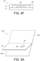
- Fig. 4F is a cross-sectional view of the printed matter 10 shown in Fig. 4D .
- moving the light source 25 closer to and away from the printed matter 10 effects no change in shape of the colored picture layer 30 of the printed matter 10.
- the present embodiment makes it possible to visually recognize the shape of the picture of the colored picture layer 30 with changes easily and surely made simply by moving the light source 25 closer to and away from the printed matter 10.
- the printed matter 10 can be used as a security material for a booklet or a card. This allows even a person who does not know luminescence property in advance to visually determine authenticity.
- a printed matter 10 having personal information has a structure that is similar to that shown in Figs. 1 to 3 , and can be incorporated into a booklet 10A such as a passport (see Figs. 5A and 5B ).
- the booklet 10A has a data page interposed between a plurality of pages 10a and 10b, and the data page is composed of a printed matter 10 of the present disclosure having personal information.
- the printed matter 10 is irradiated with excitation light from the light source 25, and the light source 25 is moved closer to and away from the printed matter 10.
- the authenticity of the printed matter 10 can be determined by checking a change in shape of the colored picture layer 30.
- the modification shown in Fig. 6 only differs in configuration of the colored picture layer 30, and other components are substantially identical to those of the embodiment shown in Figs. 1 to 3 .
- Those components of the modification shown in Fig. 6 which are identical to those of the embodiment shown in Figs. 1 to 3 are given identical signs, and a detailed description of those components is omitted.
- the printed matter 10 includes a substrate 11 made of synthetic resin, an ordinary printed layer 12 provided on the substrate 11, a colored picture layer 30 provided on the substrate 11, a luminous printed layer 20 provided so as to entirely cover the colored picture layer 30, and an overcoat layer 13 covering the ordinary printed layer 12, the colored picture layer 30, and the luminous printed layer 20, which are provided on the substrate 11.
- the colored picture layer 30 includes letters or figures, e.g. the letters "A”, “B”, and “C”. Each of these letters “A”, “B”, and “C” has a body region 30b having a uniform deep-color density and a peripheral edge region 30a located at a peripheral edge of the body region 30b. In the present embodiment, the body region 30b is a region other than the peripheral edge region.
- Each of the letters “A”, “B”, and “C” of the colored picture layer 30 is formed by a line having a predetermined width, and has an outer edge 30x facing outward and an inner edge 30y facing inward.
- the peripheral edge region 30a of each of the letters “A”, “B”, and “C” of the colored picture layer 30 is formed along the outer edge 30x and the inner edge 30y.
- the color density of the colored picture layer 30 gradually decreases toward the outer edge 30x or the inner edge 30y, whereby the density form a state of gradation in the peripheral edge region 30a.
- each of the letters "A", “B", and “C” of the colored picture layer 30 has a peripheral edge region 30a whose color density gradually decreases toward an outer edge 30x and an inner edge 30y and, the colored picture layer 30 is disposed so that its density is in a state of gradation in the peripheral edge region 30a.
- moving the light source 25 away from the printed matter 10 causes the luminous printed layer 20 on the colored picture layer 30 to emit a weak light, so that the luminous printed layer 20 comes to faintly appear outward.
- the luminous printed layer 20 comes to faintly appear outward, and to the extent that the luminous printed layer 20 faintly appears, the peripheral edge region 30a each of the letters "A", "B", and "C" of the colored picture layer 30 comes to intensely appear outward, so that the peripheral edge region 30a comes to fully appear outward.
- each of the letters "A”, "B”, and “C” of the colored picture layer 30 becomes thicker overall in shape. It should be noted that the shape of the luminous printed layer 20 does not change in particular.
- the present modification makes it possible to visually recognize the size of the picture of the colored picture layer 30 with changes easily and surely made simply by moving the light source 25 closer to and away from the printed matter 10.
- moving the light source 25 closer to the printed matter 10 causes the luminous printed layer 20 to emit intense light, whereby the picture of the colored picture layer 30 becomes thinner at the outer edge 30x.
- moving the light source 25 away from the printed matter 10 causes the luminous printed layer 20 to emit a weak light, whereby the picture of the colored picture layer 30 becomes thicker at the outer edge 30x and the shape of the outer edge 30x changes.
- moving the light source 25 closer to the printed matter 10 causes the luminous printed layer 20 to emit intense light, whereby the picture of the colored picture layer 30 becomes thinner at the inner edge 30y.
- moving the light source 25 away from the printed matter 10 causes the luminous printed layer 20 to emit a weak light, whereby the picture of the colored picture layer 30 becomes thicker at the inner edge 30y and the shape of the inner edge 30y changes.
- the printed matter according to the modification shown in Fig. 7 only differs in configuration of the colored picture layer 30, and other components are substantially identical to those of the embodiment shown in Figs. 1 to 3 .
- Those components of the modification shown in Fig. 7 which are identical to those of the embodiment shown in Figs. 1 to 3 are given identical signs, and a detailed description of those components is omitted.
- the printed matter 10 includes a substrate 11 made of synthetic resin, an ordinary printed layer 12 provided on the substrate 11, a colored picture layer 30 provided on the substrate 11, a luminous printed layer 20 provided so as to entirely cover the colored picture layer 30, and an overcoat layer 13 covering the ordinary printed layer 12, the colored picture layer 30, and the luminous printed layer 20, which are provided on the substrate 11.
- the colored picture layer 30 is composed of a first colored picture layer 31 representing palm trees and a second colored picture layer 32 having a body region 32b and a peripheral edge region 32a and representing seawater.
- the first colored picture layer 31 has a uniform high density.
- the second colored picture layer 32 has a body region 32b having a uniform high density and a peripheral edge region 32a whose color density gradually decreased from the body region 32b toward a peripheral edge 32c. This causes the second colored picture layer 32 to be disposed so that its density is in a state of gradation in the peripheral edge region 32a.
- the shape of the first colored picture layer 31, which represent the palm trees, does not change.
- moving the light source 25 away from the printed matter 10 causes the luminous printed layer 20 on the colored picture layer 30 to emit a weak light, so that the luminous printed layer 20 comes to faintly appear outward.
- the luminous printed layer 20 comes to faintly appear outward, and to the extent that the luminous printed layer 20 faintly appears, the peripheral edge region 32a of the second colored picture layer 32 comes to intensely appear outward, so that the peripheral edge region 32a of the second colored picture layer 32 comes to fully appears outward.
- the seawater represented by the second colored picture layer 32 comes to have a higher level.
- the shape of the first colored picture layer 31, which represents the palm trees, does not change.
- the present modification makes it possible to visually recognize the shapes of the pictures of the colored picture layers 31 and 32 with changes easily and surely made simply by moving the light source 25 closer to and away from the printed matter 10.
- the printed matter according to the modification shown in Fig. 8 only differs in configuration of the colored picture layer 30, and other components are substantially identical to those of the embodiment shown in Figs. 1 to 3 .
- Those components of the modification shown in Fig. 8 which are identical to those of the embodiment shown in Figs. 1 to 3 are given identical signs, and a detailed description of those components is omitted.
- the printed matter 10 includes a substrate 11 made of synthetic resin, an ordinary printed layer 12 provided on the substrate 11, a colored picture layer 30 provided on the substrate 11, a luminous printed layer 20 provided so as to entirely cover the colored picture layer 30, and an overcoat layer 13 covering the ordinary printed layer 12, the colored picture layer 30, and the luminous printed layer 20, which are provided on the substrate 11.
- the colored picture layer 30 has a series of a plurality of colored picture portions 33a, 33b, and 33c placed one after another, and the colored picture portions 33a, 33b, and 33c have star shapes that are identical to one another.
- the color density of the plurality of colored picture portions 33a, 33b, and 33c of the colored picture layer 30 continuously gradually decreases from the colored picture portion 33a on one side shown in Fig. 8 (e.g. the right side) toward the colored picture portion 33c on the other side (e.g. the left side).
- the colored picture portion 33a (indicated by solid lines) has a uniform deep-color density
- the colored picture portion 33b (indicated by dashed lines) has a uniform intermediate-color density
- the colored picture portion 33c (indicated by chain double-dashed lines) has a uniform light-color density.
- each of the colored picture portions 33a, 33b, and 33c the color density does not change, and each of the colored picture portions 33a, 33b, and 33c has a uniform density.
- moving the light source 25 gradually away from the printed matter 10 causes the luminous printed layer 20 on the colored picture layer 30 to be lower in luminescence intensity, so that the outward appearance of the luminous printed layer 20 becomes gradually fainter.
- the colored picture portion 33b which has an intermediate-color density, comes to appear outward.
- both the colored picture portion 33a and the colored picture portion 33b i.e. a total of two colored picture portions 33a and 33b, appear outward.
- the present modification makes it possible to visually recognize the printed matter 10 with changes in the number of outwardly-appearing colored picture portions 33a, 33b, and 33c of the printed matter 10 by moving the light source 25 closer to and away from the printed matter 10.
- the printed matter according to the modification shown in Fig. 9 only differs in configuration of the colored picture layer 30, and other components are substantially identical to those of the embodiment shown in Figs. 1 to 3 .
- Those components of the modification shown in Fig. 9 which are identical to those of the embodiment shown in Figs. 1 to 3 are given identical signs, and a detailed description of those components is omitted.
- the printed matter 10 includes a substrate 11 made of synthetic resin, an ordinary printed layer 12 provided on the substrate 11, a colored picture layer 30 provided on the substrate 11, a luminous printed layer 20 provided so as to entirely cover the colored picture layer 30, and an overcoat layer 13 covering the ordinary printed layer 12, the colored picture layer 30, and the luminous printed layer 20, which are provided on the substrate 11.
- the colored picture layer 30 has a plurality of colored picture layers 35a and 35b. These colored picture layers 35a and 35b are substantially identical in configuration to each other.
- the colored picture layers 35a and 35b each have a color pattern including a plurality of minute printing elements such as micro letters and minute symbols, letters, and figures having different shapes or a plurality of fine printing elements such as parallel lines, wavy lines, or dashed lines.
- the density of minute printing elements such as micro letters and minute symbols, letters, and figures is determined by the thicknesses, sizes, shapes, and density of arrangement of these minute printing elements.
- the density of fine printing elements such as parallel lines, wavy lines, or dashed lines is determined by the line thicknesses and density of arrangement of these fine printing elements.
- these parallel lines differ in width and length from one another.
- moving the light source 25 gradually away from the printed matter 10 causes the luminous printed layer 20 on the colored picture layer 30 to be lower in luminescence intensity, so that the outward appearance of the luminous printed layer 20 becomes gradually fainter.
- the parallel line of medium width and length comes to appear outward.
- the colored picture layers 35a and 35b become medium in color density.
- the present modification makes it possible to visually recognize the density (shading) of the pictures of the colored picture layers 35a and 35b with changes easily and surely made simply by moving the light source 25 closer to and away from the printed matter 10.
- the widths and lengths of the parallel lines that constitute the color patterns of the colored picture layers 35a and 35b may be adjusted between the colored picture layers 35a and 35b.
- moving the light source 25 closer to and away from the printed matter 10 makes it possible, for example, to effect a great change in shading of the color of the colored picture layer 35a and effect a small change in shading of the color of the colored picture layer 35b.
- parallel lines differing in both width and length are used as the parallel lines that constitute the color patterns of the colored picture layers 35a and 35b, this is not intended to imposed any limitation, but parallel lines differing in either width or length may be used.
- a luminous body may be mixed in a substrate 11A.
- the substrate 11A include paper such as coated paper, copy paper, paper, and high-quality paper, that contains a whitening agent containing a fluorescent body.
- a fluorescent body can be kneaded into the resin substrate 11A (see Fig. 11A ).
- the ordinary printed layer 12 and the colored picture layer 30 can be printed with an inkjet or toner printer installed in a home, a convenience store, or other places, as the ordinary printed layer 12 and the colored picture layer 30 are formed with normal print ink as mentioned above. This makes it possible to use a simple printer to easily and simply produce a printed matter 10 constituting a ticket, a certificate, or other documents.
- a printed matter 10 may have a laser-light-coloring-agent-containing resin substrate 11B containing a coloring agent that produces a color by laser printing and a luminous printed layer 20 provided on the resin substrate 11B (see Fig. 11B ).
- laser printing causes the coloring agent contained in the resin substrate 11B to produce a color.
- Such a printed matter 10 having a laser-light-coloring-agent-containing resin substrate 11B constitutes, for example, a certification card or a data page incorporated into a booklet such as a passport.
- an overcoat layer 13 is provided on the substrate 11B so as to cover the luminous printed layer 20. Note, however, that the overcoat layer 13 does not necessarily need to be provided.
- a printed matter 10 may have a color-change-substance-containing paper substrate (thermal paper) 11C containing a color-change substance that changes its color upon heating by a thermal head 40 and a luminous printed layer 20 provided on the paper substrate 11C (see Fig. 11C ).
- thermal head 40 to heat the color-change substance contained in the paper substrate 11C makes it possible to cause the color-change substance contained in the substrate 11B to change its color within the region of the luminous printed layer 20 to form a colored picture layer 30.
- an overcoat layer 13 is provided on the substrate 11C so as to cover the luminous printed layer 20. Note, however, that the overcoat layer 13 does not necessarily need to be provided.
- Figs. 1 to 3 has illustrated a case where the printed matter 10 constitutes a card such as a certification card, this is not intended to impose any limitation, but as shown in Figs. 12 and 13 , the printed matter 10 may constitute, for example, a gift certificate.
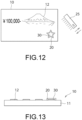
- Fig. 12 is a plan view showing a printed matter 10
- Fig. 13 is a side view of the printed matter 10 shown in Fig. 12 .
- such a printed matter 10 constituting a gift certificate includes a substrate 11, an ordinary printed layer 12 provided on the substrate 11, a colored picture layer 30 provided on the substrate 11, and a luminous printed layer 20 provided so as to entirely cover the colored picture layer 30.
- the substrate 11 is made of polycarbonate (PC), polyethylene terephthalate (PET), amorphous polyester (PET-G), polyvinyl chloride (PVC), or polypropylene (PP).
- the substrate 11 may be a paper substrate.
- the ordinary printed layer 12 and the colored picture layer 30 are formed with normal print ink containing a common pigment or dye.
- a printing method a printing method, such as offset printing, silk screen printing, or inkjet printing, that allows printing on the substrate is selected as appropriate.
- the hues of the ordinary printed layer 12 and the colored picture layer 30 under visible light are chromatic colors, and do not have transparency. Any color or ink that can be printed by the printing method may be used.
- the luminous printed layer 20 is obtained by doing printing so as to entirely cover the colored picture layer 30 with a luminous body that emits light upon irradiation with excitation light.
- the hue of the luminous printed layer 20 may be either colorless or colorless and transparent, may be the body color of a pigment, or may be the chromatic color of color pigments mixed or a chromatic color having transparency.
- the luminous printed layer 20 of the printed matter needs to be without incongruity in color and appearance with the hue of the colored picture layer 30.
- the tint of color pigments mixed is deep, the luminous color of the luminous body is absorbed, with the result that it becomes hard to visually recognize a change in the luminous color; therefore, it is preferable that the chromatic color of a color pigment be light. Note, however, that since there are many types of ink or color pigment available in the world and there are more than several hundred types of ink and color pigment, a preferred form or composition ratio changes accordingly depending on the type of ink or pigment.
- the present modification makes it possible to visually recognize the shape of the picture of the colored picture layer 30 with changes easily and surely made simply by moving the light source 25 closer to and away from the printed matter 10.
- the printed matter 10 may include a substrate 11, a luminous printed layer 20 provided on the substrate 11, and a colored picture layer 30 provided on the luminous printed layer 20 by printing (see Fig. 10 ).
- the printed matter 10 may include a substrate 11A into which a luminous body has been kneaded, a colored picture layer 30 provided on the substrate 11A by printing, and an ordinary printed layer 12 provided on the substrate 11A by printing (see Fig. 11A ).
- Figs. 14A and 14B only differs in configuration of the colored picture layer 30, and other components are substantially identical to those of the embodiment shown in Figs. 1 to 3 .
- Those components of the additional modification shown in Figs. 14A and 14B which are identical to those of the embodiment shown in Figs. 1 to 3 are given identical signs, and a detailed description of those components is omitted.
- Fig. 14A is a plan view showing an additional modification
- Fig. 14B is a cross-sectional view of a printed matter shown in Fig. 14A .
- the printed matter 10 includes a substrate 11 made of synthetic resin, an ordinary printed layer 12 (see Fig. 3 ) provided on the substrate 11, a colored picture layer 30 provided on the substrate 11, a luminous printed layer 20 provided so as to entirely cover the colored picture layer 30, and an overcoat layer 13 covering the ordinary printed layer 12, the colored picture layer 30, and the luminous printed layer 20, which are provided on the substrate 11.
- the colored picture layer 30 has a body region 30b, located in the center, that has a uniform deep-color density and a peripheral edge region 30a, located outside the body region 30b, whose color density gradually decreases toward a peripheral edge 30c.
- the body region 30b is a region other than the peripheral edge region 30a.
- the body region 30b of the colored picture layer 30 has a circular shape, and the peripheral edge region 30a provided outside the body region 30b has a star shape.
- the luminous printed layer 20 surrounds the colored picture layer 30 and has a hexagonal shape.
- the colored picture layer 30 has a peripheral edge region 30a whose color density gradually decreases toward a peripheral edge 30c, and the colored picture layer 30 is disposed so that its density is in a state of gradation in the peripheral edge region 30a.
- the body region 30b of the colored picture layer 30, located in the center, that has a circular shape comes to clearly appear outward. That is, to the extent that the luminous printed layer 20 clearly appears, the peripheral edge region 30a of the colored picture layer 30 comes to faintly appear outward, so that the peripheral edge region 30a becomes partially missing at the peripheral edge 30c. As a result of this, the circular shape of the body region 30b of the colored picture layer 30 clearly appears outward.
- moving the light source 25 away from the printed matter 10 causes the luminous printed layer 20 on the colored picture layer 30 to emit a weak light, so that the luminous printed layer 20 comes to faintly appear outward.
- the peripheral edge region 30a of the colored picture layer 30 comes to intensely appear outward, so that the peripheral edge region 30a comes to fully appear outward.
- the star shape of the peripheral edge region 30a of the colored picture layer 30 clearly appears outward.
- the circular shape of the body region 30b of the colored picture layer 30 and the star shape of the peripheral edge region 30a can be easily and surely alternately displayed outward simply by moving the light source 25 closer to and away from the printed matter 10.
- Figs. 15A and 15B only differs in configuration of the luminous printed layer 20, and other components are substantially identical to those of the embodiment shown in Figs. 1 to 3 .
- Those components of the modifications shown in Figs. 15A and 15B which are identical to those of the embodiment shown in Figs. 1 to 3 are given identical signs, and a detailed description of those components is omitted.
- Fig. 15A is a cross-sectional view showing an additional modification
- Fig. 15B is a cross-sectional view showing another additional modification.
- the printed matter 10 includes a substrate 11 made of synthetic resin, an ordinary printed layer 12 (see Fig. 3 ) provided on the substrate 11, a colored picture layer 30 provided on the substrate 11, a luminous printed layer 20 provided so as to entirely cover the colored picture layer 30, and an overcoat layer 13 covering the ordinary printed layer 12, the colored picture layer 30, and the luminous printed layer 20, which are provided on the substrate 11.
- the colored picture layer 30 has a body region 30b, located in the center, that has a uniform deep-color density and a peripheral edge region 30a, located outside the body region 30b, whose color density gradually decreases toward a peripheral edge 30c.
- the body region 30b is a region other than the peripheral edge region 30a.
- the luminous printed layer 20 covers only the peripheral edge region 30a of the colored picture layer 30.
- the colored picture layer 30 has a peripheral edge region 30a whose color density gradually decreases toward a peripheral edge 30c, and the colored picture layer 30 is disposed so that its density is in a state of gradation in the peripheral edge region 30a.
- moving the light source 25 away from the printed matter 10 causes the luminous printed layer 20 on the colored picture layer 30 to emit a weak light, so that the luminous printed layer 20 comes to faintly appear outward.
- the luminous printed layer 20 comes to faintly appear outward, and to the extent that the luminous printed layer 20 faintly appears, the peripheral edge region 30a of the colored picture layer 30 comes to intensely appear outward, so that the peripheral edge region 30a comes to fully appear outward.
- the present modification makes it possible to visually recognize the shape of the picture of the colored picture layer 30 with changes easily and surely made simply by moving the light source 25 closer to and away from the printed matter 10. Further, since the luminous printed layer 20 covers only the peripheral edge region 30a of the colored picture layer 30, the amount of ink that is used for fabricating the luminous printed layer 20 can be reduced.
- Fig. 15A has illustrated an example in which the luminous printed layer 20 covers only the peripheral edge region 30a of the colored picture layer 30, this is not intended to impose any limitation, but the luminous printed layer 20 may cover the peripheral edge region 30a of the colored picture layer 30 and part of the body region 30b beside the peripheral edge region 30a (see Fig. 15B ).
- Example 1 has illustrated an example in which the luminous printed layer 20 covers only the peripheral edge region 30a of the colored picture layer 30, this is not intended to impose any limitation, but the luminous printed layer 20 may cover the peripheral edge region 30a of the colored picture layer 30 and part of the body region 30b beside the peripheral edge region 30a (see Fig. 15B ).
- the present specific example corresponds to the embodiment shown in Figs. 1 to 3 and Figs. 4A to 4C .
- the substrate 11 paper free of a fluorescent whitening agent was used. Further, as the body region 30b to peripheral edge region 30a of the colored picture layer 30, commercially-available black ink was used, and as the luminous printed layer 20, Y 2 O 2 S:Eu was used. An offset printing method was used to give a halftone-dot printed matter 10. In this case, the peripheral edge region 30a was subjected to gradation printing with changes in halftone-dot area ratio from 100% to 0%.
Landscapes
- Physics & Mathematics (AREA)
- General Physics & Mathematics (AREA)
- Health & Medical Sciences (AREA)
- General Health & Medical Sciences (AREA)
- Toxicology (AREA)
- Engineering & Computer Science (AREA)
- Computer Vision & Pattern Recognition (AREA)
- Spectroscopy & Molecular Physics (AREA)
- Printing Methods (AREA)
- Credit Cards Or The Like (AREA)
- Inspection Of Paper Currency And Valuable Securities (AREA)
Abstract
Description
- The present disclosure relates to a printed matter including a substrate and a luminous printed layer containing a luminous body and a combination of a light source and a printed matter.
- A printed matter, such as securities, that requires security includes a substrate and a luminous printed layer provided on the substrate through the use of a luminous body, and has a structure that prevents forgery or alteration or discriminates between a counterfeit product and a genuine product. Further, in general, a colored picture layer may be formed on the substrate separately from the luminous printed layer.
- As a method for determining the authenticity of a printed matter given such a luminous printed layer, a method by which a printed matter is irradiated with electromagnetic waves or radiation such as excitation light containing energy capable of exciting a luminous body and sensing is done with a read device or machine such as a sensor is commonly used.
- In a case where a luminous body is a visible luminous body, there is also a method for authenticating the emission of light with a human eye by using a simple light source such as a black light as an excitation source. In such a case, for convenience in surely authenticating a printed matter, it is preferable that the shape, size, number, or shading of a picture or pictures of a colored picture layer provided on a substrate together with a luminous printed layer be visually recognized with changes made by causing excitation light emitted by the black light to move closer to and away from the printed matter.
-
- PTL 1:
Japanese Unexamined Patent Application Publication (Translation of PCT Application) No. 2011-514937 - PTL 2:
Japanese Patent No. 5610121 - The present disclosure was made in view of visually identifying the emission of light through the use of a commonly available light source such as a black light, and has as an object to provide a printed matter that can be visually recognized with changes easily and surely made in shape, size, number, or shading of a picture or pictures of a colored picture layer simply by moving a light source closer to and away from the printed matter and a combination of a light source and a printed matter.
- The present disclosure is directed to a printed matter that is irradiated with excitation light from a light source, the printed matter including: a substrate; a luminous printed layer, provided on the substrate, that contains a luminous body; and a colored picture layer, provided on the substrate, that contains a pigment or a dye, wherein the luminous printed layer and the colored picture layer overlap each other, the colored picture layer has a body region and a peripheral edge region, and a color density of the colored picture layer of the peripheral edge region gradually decreases toward a peripheral edge of the colored picture layer.
- The present disclosure is directed to a printed matter that is irradiated with excitation light from a light source, the printed matter including: a substrate containing a luminous body; and a colored picture layer, provided on the substrate, that contains a pigment or a dye, wherein the colored picture layer has a body region and a peripheral edge region, and a color density of the colored picture layer of the peripheral edge region gradually decreases toward a peripheral edge of the colored picture layer.
- The present disclosure is directed to the printed matter, wherein the colored picture layer is formed by halftone-dot printing, and in the peripheral edge region, a halftone-dot density of the colored picture layer gradually decreases toward the peripheral edge.
- The present disclosure is directed to the printed matter, wherein the colored picture layer includes a plurality of minute printing elements or fine printing elements, and in the peripheral edge region, a density of the minute printing elements or fine printing elements of the colored picture layer gradually decreases toward the peripheral edge.
- The present disclosure is directed to the printed matter, wherein the colored picture layer forms a letter or a figure, and the peripheral edge region is formed along an outer edge of the letter or the figure.
- The present disclosure is directed to the printed matter, wherein the colored picture layer forms a letter or a figure, and the peripheral edge region is formed along an inner edge of the letter or the figure.
- The present disclosure is directed to a printed matter that is irradiated with excitation light from a light source, the printed matter including: a substrate; a luminous printed layer, provided on the substrate, that contains a luminous body; and a colored picture layer, provided on the substrate, that contains a pigment or a dye, wherein the luminous printed layer and the colored picture layer overlap each other, the colored picture layer includes a series of a plurality of colored picture portions placed one after another, and a color density of the plurality of colored picture portions continuously gradually decreases from a colored picture portion on one side toward a colored picture portion on the other side.
- The present disclosure is directed to a printed matter that is irradiated with excitation light from a light source, the printed matter including: a substrate containing a luminous body; and a colored picture layer, provided on the substrate, that contains a pigment or a dye, wherein the colored picture layer includes a series of a plurality of colored picture portions placed one after another, and a color density of the plurality of colored picture portions continuously gradually decreases from a colored picture portion on one side toward a picture portion on the other side.
- The present disclosure is directed to a printed matter that is irradiated with excitation light from a light source, the printed matter including: a substrate; a luminous printed layer, provided on the substrate, that contains a luminous body; and a colored picture layer, provided on the substrate, that contains a pigment or a dye, wherein the luminous printed layer and the colored picture layer overlap each other, and the colored picture layer forms a color pattern including a plurality of minute printing elements or fine printing elements having different shapes.
- The present disclosure is directed to a printed matter that is irradiated with excitation light from a light source, the printed matter including: a substrate containing a luminous body; and a colored picture layer, provided on the substrate, that contains a pigment or a dye, wherein the colored picture layer forms a color pattern including a plurality of minute printing elements or fine printing elements having different shapes.
- The present disclosure is directed to the printed matter, further comprising an overcoat layer, provided on the substrate, that covers at least the colored picture layer.
- A booklet includes the printed matter described above.
- A combination of a light source and a printed matter includes the printed matter described above and the light source that emits the excitation light.
- A method for determining authenticity of a printed matter with the combination of a light source and a printed matter described above includes the steps of irradiating a surface of the printed matter with the excitation light from the light source and determining the authenticity of the printed matter by visually recognizing the printed matter with changes made in shape, size, number, or shading of an outwardly-appearing picture or pictures of the colored picture layer by moving the light source closer to and away from the printed matter.
- The present disclosure makes it possible to visually recognize the shape, size, number, or shading of a picture or pictures of the colored picture layer with changes easily and surely made simply by moving the light source closer to and away from the printed matter.
-
- [
Fig. 1] Fig. 1 is a diagram showing a luminous printed layer and a colored picture layer of a printed matter according to the present embodiment. - [
Fig. 2] Fig. 2 is a plan view showing a printed matter constituting a certification card according to the present embodiment. - [
Fig. 3] Fig. 3 is a side view of the printed matter shown inFig. 2 . - [
Fig. 4A] Fig. 4A is a diagram showing the action of a printed matter according to the present embodiment. - [
Fig. 4B] Fig. 4B is a diagram showing the action of the printed matter according to the present embodiment. - [
Fig. 4C] Fig. 4C is a cross-sectional view of the printed matter shown inFigs. 4A and4B . - [
Fig. 4D] Fig. 4D is a diagram showing the action of a printed matter according to a comparative example. - [
Fig. 4E] Fig. 4E is a diagram showing the action of the printed matter according to the comparative example. - [
Fig. 4F] Fig. 4F is a cross-sectional view of the printed matter shown inFigs. 4D and 4E . - [
Fig. 5A] Fig. 5A is a diagram showing a booklet according to an applied example of the present embodiment. - [
Fig. 5B] Fig. 5B is a diagram showing a state where the booklet shown inFig. 5A is irradiated with excitation light. - [
Fig. 6] Fig. 6 is a diagram showing a printed matter according to a modification. - [
Fig. 7] Fig. 7 is a diagram showing a printed matter according to a modification. - [
Fig. 8] Fig. 8 is a diagram showing a printed matter according to a modification. - [
Fig. 9] Fig. 9 is a diagram showing a printed matter according to a modification. - [
Fig. 10] Fig. 10 is a diagram showing a printed matter according to a modification. - [
Fig. 11A] Fig. 11A is a diagram showing a printed matter according to a modification. - [
Fig. 11B] Fig. 11B is a diagram showing a printed matter according to another modification. - [
Fig. 11C] Fig. 11C is a diagram showing a printed matter according to another modification. - [
Fig. 12] Fig. 12 is a plan view showing a printed matter constituting a gift certificate. - [
Fig. 13] Fig. 13 is a side view of the printed matter shown inFig. 12 . - [
Fig. 14A] Fig. 14A is a diagram showing a printed matter according to an additional modification. - [
Fig. 14B] Fig. 14B is a cross-sectional view of the printed matter shown inFig. 14A . - [
Fig. 15A] Fig. 15A is a cross-sectional view showing a printed matter according to an additional modification. - [
Fig. 15B] Fig. 15B is a cross-sectional view showing a printed matter according to an additional modification. - In the following, a printed matter and a combination of a light source and a printed matter according to the present embodiment are described with reference to the drawings.
- First, a printed
matter 10 according to the present embodiment is described with reference toFigs. 1 to 3 . The printedmatter 10 can be used as a security material for a booklet or a card. The printedmatter 10 per se may be a booklet such as a passport, a data page of a passport, a gift certificate, or a bill, or may be contained in a layer of an ID, a ticket, or a card (contact or non-contact integrated-circuit (IC) card). As shown inFigs. 1 to 3 , the printedmatter 10 is irradiated, for example, with ultraviolet light (UV light) with a center wavelength of 365 nm from alight source 25 such as a UV discharge tube constituting a black light. The UV light emitted by the light source functions as excitation light that excites a luminous body of the after-mentioned luminous printedlayer 20 to emit light. It should be noted that thelight source 25 may be a UV-LED light source. - First, the present embodiment illustrates a case where the printed
matter 10 constitutes a card such as a certification card. As shown inFigs. 1 to 3 , such a printedmatter 10 constituting a certification card includes asubstrate 11 made of synthetic resin, an ordinary printedlayer 12 provided on thesubstrate 11 and composed of letters, numbers, or other characters, acolored picture layer 30 provided on thesubstrate 11, a luminous printedlayer 20 provided so as to entirely cover thecolored picture layer 30, and anovercoat layer 13 covering the ordinary printedlayer 12, thecolored picture layer 30, and the luminous printedlayer 20, which are provided on thesubstrate 11. Note here thatFig. 2 is a plan view showing the printedmatter 10 andFig. 3 is a side view showing the printedmatter 10. - Of them, the
substrate 11 is made of polycarbonate (PC), polyethylene terephthalate (PET), amorphous polyester (PET-G), polyvinyl chloride (PVC), or polypropylene (PP). Alternatively, thesubstrate 11 may be a paper substrate. - Further, the
overcoat layer 13 is made of polycarbonate (PC), polyethylene terephthalate (PET), amorphous polyester (PET-G), polyvinyl chloride (PVC), or polypropylene (PP). - Further, the ordinary printed
layer 12 and thecolored picture layer 30 are formed with normal print ink containing a common pigment or dye. As a printing method, a printing method, such as offset printing, silk screen printing, or inkjet printing, that allows printing on the substrate is selected as appropriate. The hues of the ordinary printedlayer 12 and thecolored picture layer 30 under visible light are chromatic colors, and do not have transparency. Any color or ink that can be printed by the printing method may be used. It should be noted that thecolored picture layer 30 will be further described later. - Further, the luminous printed
layer 20 is obtained by doing printing so as to entirely cover thecolored picture layer 30 with a luminous body that emits light upon irradiation with excitation light. In a case where the luminous printedlayer 20 is printed all over thecolored picture layer 30, the hue of the luminous printedlayer 20 may be either colorless or colorless and transparent, may be the body color of a pigment, or may be the chromatic color of color pigments mixed or a chromatic color having transparency. The luminous printedlayer 20 of the printed matter needs to be without incongruity in color and appearance with the hue of thecolored picture layer 30. Further, if the tint of color pigments mixed is deep, the luminous color of the luminous body is absorbed, with the result that it becomes hard to visually recognize a change in the luminous color; therefore, it is preferable that the chromatic color of a color pigment be light. Note, however, that since there are many types of ink or color pigment available in the world and there are more than several hundred types of ink and color pigment, a preferred form or composition ratio changes accordingly depending on the type of ink or pigment. - In the present embodiment, a usable example of a luminous body that constitutes the luminous body of the luminous printed
layer 20 is a blue luminous body (such as BaMgAl10O17:Eu), a green luminous body (such as SrAl204:Eu,Dy, Sr4Al14025:Eu,Dy, ZnO, Zn2GeO4:Mn), a red luminous body (such as YVO4:Bi,Eu, Y2O2S:Eu), or a while luminous body (such as a blue, green, and red mixed luminous body "Y2O2S:Eu, Zn2GeO4:Mn, BaMgAl10O17:Eu"). - In the present embodiment, the luminous printed
layer 20 is formed by printing with luminous body ink containing the aforementioned luminous body. As a printing method, a printing method, such as offset printing, silk screen printing, or inkjet printing, that allows printing on the substrate is selected as appropriate. - As a method for applying the luminous body ink onto the
colored picture layer 30 of thesubstrate 11, for example, by printing or coating, a publicly-known printing method may be used. A method, for example, for printing such as intaglio printing, anastatic printing, offset printing, screen printing, gravure printing, flexo printing, and inkjet printing or coating. The luminous body ink may be applied onto thecolored picture layer 30 of thesubstrate 11 by a combination of these printing methods. - Note here that the luminous body ink further contains, for example, aqueous varnish, solvent varnish, oxidative polymerizable varnish, radiation curable varnish, radiation curable and oxidative polymerizable hybrid varnish in addition to the luminous body.
- Further, the luminous body ink contains various types of varnish as mentioned earlier, and has its viscosity or other properties adjusted so that the various types of varnish may be mixed up. In terms of luminescence intensity, it is preferable that the blending ratio of the luminous body be higher than or equal to 1 mass%, more preferably higher than or equal to 3 mass%, or even more preferably higher than or equal to 5 mass%, although the blending ratio varies depending on how the luminous printed
layer 20 is formed. Meanwhile, in terms of ease of formation an ink layer, it is preferable that the blending ratio be lower than or equal to 60 mass% , more preferably lower than or equal to 50 mass%, or even more preferably lower than or equal to 40 mass%. - The luminous body ink is produced by sufficiently dispersing the luminous body in the varnish with a three-roll mill, a ball mill, a bead mill, or other mills. It should be noted that a kneading method and an appropriate viscosity are selected as appropriate depending on how the luminous body ink is applied.
- The luminous body ink may be formed into ink or paste by mixing another color material or functional material to such an extent as not to prevent emission of light, and is applied onto the
colored picture layer 30 provided in advance onto thesubstrate 11. That is, the ordinary printedlayer 12 and thecolored picture layer 30, which are formed in advance with normal print ink and form a printed picture, are provided on thesubstrate 11, and the luminous body ink is applied onto thecolored picture layer 30 of thesubstrate 11 to form the luminous printedlayer 20. - Next, the
colored picture layer 30 provided on thesubstrate 11 is further described with reference toFig. 1 . As shown inFig. 1 , thecolored picture layer 30 is provided on thesubstrate 11 through the use of print ink, and on thecolored picture layer 30, the luminous printedlayer 20 is provided through the use of luminous body ink so as to entirely cover thecolored picture layer 30. - In the present embodiment, the
colored picture layer 30 has a star shape having aperipheral edge region 30a located at a peripheral edge and a region other than theperipheral edge region 30a, specifically abody region 30b located in the center. Of them, thecolored picture layer 30 of theperipheral edge region 30a has its color density gradually decreasing toward aperipheral edge 30c of thecolored picture layer 30, and thecolored picture layer 30 is disposed so that its density is in a state of gradation in theperipheral edge region 30a. - Further, the luminous printed
layer 20 too has a star shape that is similar to that of thecolored picture layer 30. Further, in a case where thecolored picture layer 30 is formed by halftone-dot printing, thebody region 30a has a halftone-dot density of, for example, 100%. Further, theperipheral edge region 30a has its halftone-dot density gradually decreasing from thebody region 30b toward theperipheral edge 30c, and thecolored picture layer 30 is disposed so that its density is in a state of gradation in theperipheral edge region 30a. Specifically, theperipheral edge region 30a of thecolored picture layer 30 has its halftone-dot density decreasing, for example, from 100% to 0% from thebody region 30b toward theperipheral edge 30c. This causes theperipheral edge region 30a of thecolored picture layer 30 to exhibit outward blurring of colors. Further, the formation of thecolored picture layer 30 by halftone-dot printing makes it possible to easily and simply achieve an ordinary state of gradation. Incidentally, theperipheral edge region 30a of thecolored picture layer 30 has its halftone-dot density decreasing, for example, from 100% to 0% from thebody region 30b toward theperipheral edge 30c, and in this case, the halftone-dot density may vary from 100%, 99%, 98%, and 97% to 5%, 4%, 3%, 2%, 1%, and 0% in decrements of 1%. Alternatively, the halftone-dot density may vary in decrements of 0.1% or 0.001%, and there is no need to place upper or lower limits on the decrements. - Alternatively, the
colored picture layer 30 may be printed not by halftone-dot printing but by using minute printing elements such as micro letters and minute symbols, letters, and figures or fine printing elements such as parallel lines, wavy lines, or dashed lines, and in this case, thebody region 30b of thecolored picture layer 30 has its minute printing element or fine printing element density of, for example, 100%. Further, theperipheral edge region 30a has its minute printing element or fine printing element density gradually decreasing from thebody region 30b toward theperipheral edge 30c, and thecolored picture layer 30 is disposed so that its density is in a state of gradation in theperipheral edge region 30a. Specifically, theperipheral edge region 30a of thecolored picture layer 30 has its minute printing element or fine printing element density decreasing, for example, from 100% to 0% from thebody region 30b toward theperipheral edge 30c. This causes theperipheral edge region 30a of thecolored picture layer 30 to exhibit outward blurring of colors. It should be noted that in the present embodiment, the density of minute printing elements such as micro letters and minute symbols, letters, and figures is determined by the thicknesses, sizes, shapes, and density of arrangement of these minute printing elements. On the other hand, the density of fine printing elements such as parallel lines, wavy lines, or dashed lines is determined by the line thicknesses and density of arrangement of these fine printing elements. Further, in a case where thecolored picture layer 30 is printed by using fine printing elements, disposing thecolored picture layer 30 in a state of gradation makes it possible to expect a higher anticounterfeit effect in addition to the anticounterfeit effect of printing of the fine printing elements per se. - In this way, the
colored picture layer 30 has aperipheral edge region 30a whose color density gradually decreases toward aperipheral edge 30c, and thecolored picture layer 30 is disposed so that its density is in a state of gradation in theperipheral edge region 30a. In the present embodiment, in a case where thelight source 25 is moved closer to and away from the printedmatter 10, e.g. when thelight source 25 is moved closer to the printedmatter 10, the luminous printedlayer 20 on thecolored picture layer 30 emits intense light, with the result that the luminous printedlayer 20 comes to clearly appear outward. In this case, the luminous printedlayer 20 comes to clearly appear outward, and to the extent that the luminous printedlayer 20 clearly appears outward, theperipheral edge region 30a of thecolored picture layer 30 comes to faintly appear outward, so that theperipheral edge region 30a becomes partially missing at theperipheral edge 30c. In this case, thecolored picture layer 30 allows observation of a picture of thebody region 30b per se and a picture of the luminous printedlayer 20 per se. - On the other hand, when the
light source 25 is moved away from the printedmatter 10, the luminous printedlayer 20 on thecolored picture layer 30 emits a weak light, so that the luminous printedlayer 20 comes to faintly appear outward. In this case, the luminous printedlayer 20 comes to faintly appear outward, and to the extent that the luminous printedlayer 20 faintly appears, theperipheral edge region 30a of thecolored picture layer 30 comes to intensely appear outward, so that theperipheral edge region 30a comes to fully appear outward. - Next, the action of the present embodiment composed of such components is described with reference to
Figs. 4A to 4F . - First, as shown in
Figs. 4A to 4C , the aforementioned printedmatter 10 is prepared, and an inspector irradiates the printedmatter 10 with UV light from thelight source 25. In this case, the printedmatter 10 is irradiated with UV light with a center wavelength of 365 nm from thelight source 25. Next, the inspector moves thelight source 25 closer to and away from the printedmatter 10. - As mentioned above, the
colored picture layer 30 has aperipheral edge region 30a whose color density gradually decreases toward aperipheral edge 30c, and thecolored picture layer 30 is disposed so that its density is in a state of gradation in theperipheral edge region 30a. - For this reason, moving the
light source 25 closer to the printedmatter 10 causes the luminous printedlayer 20 on thecolored picture layer 30 to emit intense light, with the result that the luminous printedlayer 20 comes clearly appear outward (seeFig. 4A ). In this case, the luminous printedlayer 20 comes to clearly appear outward, and to the extent that the luminous printedlayer 20 clearly appears, theperipheral edge region 30a of thecolored picture layer 30 comes to faintly appear outward, so that theperipheral edge region 30a becomes partially missing at theperipheral edge 30c. As a result of this, the star-shapedcolored picture layer 30 becomes smaller overall in shape. It should be noted that the shape of the luminous printedlayer 20 does not change in particular. Note here thatFig. 4C is a cross-sectional view of the printedmatter 10 shown inFig. 4A . - On the other hand, moving the
light source 25 away from the printedmatter 10 causes the luminous printedlayer 20 on thecolored picture layer 30 to emit a weak light, so that the luminous printedlayer 20 comes to faintly appear outward (seeFig. 4B ). In this case, the luminous printedlayer 20 comes to faintly appear outward, and to the extent that the luminous printedlayer 20 faintly appears, theperipheral edge region 30a of thecolored picture layer 30 comes to intensely appear outward, so that theperipheral edge region 30a comes to fully appear outward. As a result of this, the star-shapedcolored picture layer 30 becomes larger overall in shape. It should be noted that the shape of the luminous printedlayer 20 does not change in particular. - At this point in time, the inspector checks the shape of the
colored picture layer 30 of the printedmatter 10 at this point in time by moving thelight source 25 closer to and away from the printedmatter 10. Then, the inspector can surely determine the authenticity of the printedmatter 10 on the basis of a predetermined change in shape of thecolored picture layer 30 effected by moving thelight source 25 closer to and away from the printedmatter 10 and a change in shape of thecolored picture layer 30 at the time of inspection. - Next, a printed
matter 10 according to a comparative example is described with reference toFigs. 4D to 4F . - In the printed
matter 10 according to the comparative example, thecolored picture layer 30 has a uniform color density as a whole, and thecolored picture layer 30 has no peripheral edge region whose color density gradually decreases toward aperipheral edge 30c. - In
Figs. 4D to 4F , other components are substantially identical to those of the present embodiment shown inFigs. 4A to 4C . - In the comparative example shown in
Figs. 4D and4F , moving thelight source 25 closer to the printedmatter 10 causes the luminous printedlayer 20 to clearly appear, but since thecolored picture layer 30 has no peripheral edge region whose color density gradually decreases toward aperipheral edge 30c, thecolored picture layer 30 does not become smaller in shape (seeFig. 4D ). Note here thatFig. 4F is a cross-sectional view of the printedmatter 10 shown inFig. 4D . - Further, moving the
light source 25 away from the printedmatter 10 causes the luminous printedlayer 20 to faintly appear, but since thecolored picture layer 30 has no peripheral edge region whose color density gradually decreases toward aperipheral edge 30c, thecolored picture layer 30 does not become larger in shape (seeFig. 4D ). - Thus, in the comparative example, moving the
light source 25 closer to and away from the printedmatter 10 effects no change in shape of thecolored picture layer 30 of the printedmatter 10. - As noted above, the present embodiment makes it possible to visually recognize the shape of the picture of the
colored picture layer 30 with changes easily and surely made simply by moving thelight source 25 closer to and away from the printedmatter 10. - Further, in the present embodiment, the printed
matter 10 can be used as a security material for a booklet or a card. This allows even a person who does not know luminescence property in advance to visually determine authenticity. Specifically, such a printedmatter 10 having personal information has a structure that is similar to that shown inFigs. 1 to 3 , and can be incorporated into abooklet 10A such as a passport (seeFigs. 5A and5B ). As shown inFigs. 5A and5B , thebooklet 10A has a data page interposed between a plurality ofpages matter 10 of the present disclosure having personal information. Moreover, the printedmatter 10 is irradiated with excitation light from thelight source 25, and thelight source 25 is moved closer to and away from the printedmatter 10. At this point in time, the authenticity of the printedmatter 10 can be determined by checking a change in shape of thecolored picture layer 30. - Next, printed matters according to modifications of the present embodiment are described with reference to
Figs. 6 to 13 . - The modification shown in
Fig. 6 only differs in configuration of thecolored picture layer 30, and other components are substantially identical to those of the embodiment shown inFigs. 1 to 3 . Those components of the modification shown inFig. 6 which are identical to those of the embodiment shown inFigs. 1 to 3 are given identical signs, and a detailed description of those components is omitted. - As shown in
Fig. 6 , the printedmatter 10 includes asubstrate 11 made of synthetic resin, an ordinary printedlayer 12 provided on thesubstrate 11, acolored picture layer 30 provided on thesubstrate 11, a luminous printedlayer 20 provided so as to entirely cover thecolored picture layer 30, and anovercoat layer 13 covering the ordinary printedlayer 12, thecolored picture layer 30, and the luminous printedlayer 20, which are provided on thesubstrate 11. - Of them, the
colored picture layer 30 includes letters or figures, e.g. the letters "A", "B", and "C". Each of these letters "A", "B", and "C" has abody region 30b having a uniform deep-color density and aperipheral edge region 30a located at a peripheral edge of thebody region 30b. In the present embodiment, thebody region 30b is a region other than the peripheral edge region. - Each of the letters "A", "B", and "C" of the
colored picture layer 30 is formed by a line having a predetermined width, and has anouter edge 30x facing outward and aninner edge 30y facing inward. In this case, theperipheral edge region 30a of each of the letters "A", "B", and "C" of thecolored picture layer 30 is formed along theouter edge 30x and theinner edge 30y. - Further, in the
peripheral edge region 30a of each of the letters "A", "B", and "C" of thecolored picture layer 30, the color density of thecolored picture layer 30 gradually decreases toward theouter edge 30x or theinner edge 30y, whereby the density form a state of gradation in theperipheral edge region 30a. - In
Fig. 6 , each of the letters "A", "B", and "C" of thecolored picture layer 30 has aperipheral edge region 30a whose color density gradually decreases toward anouter edge 30x and aninner edge 30y and, thecolored picture layer 30 is disposed so that its density is in a state of gradation in theperipheral edge region 30a. - For this reason, moving the
light source 25 closer to the printedmatter 10 causes the luminous printedlayer 20 on thecolored picture layer 30 to emit intense light, with the result that the luminous printedlayer 20 comes to clearly appear outward. In this case, the luminous printedlayer 20 comes to clearly appear outward, and to the extent that the luminous printedlayer 20 clearly appears, theperipheral edge region 30a of each of the letters "A", "B", and "C" of thecolored picture layer 30 comes to faintly appear outward, so that theperipheral edge region 30a becomes partially missing at theouter edge 30x and theinner edge 30y. As a result of this, each of the letters "A", "B", and "C" of thecolored picture layer 30 becomes thinner overall in shape. It should be noted that the shape of the luminous printedlayer 20 does not change in particular. - On the other hand, moving the
light source 25 away from the printedmatter 10 causes the luminous printedlayer 20 on thecolored picture layer 30 to emit a weak light, so that the luminous printedlayer 20 comes to faintly appear outward. In this case, the luminous printedlayer 20 comes to faintly appear outward, and to the extent that the luminous printedlayer 20 faintly appears, theperipheral edge region 30a each of the letters "A", "B", and "C" of thecolored picture layer 30 comes to intensely appear outward, so that theperipheral edge region 30a comes to fully appear outward. - As a result of this, each of the letters "A", "B", and "C" of the
colored picture layer 30 becomes thicker overall in shape. It should be noted that the shape of the luminous printedlayer 20 does not change in particular. - In this way, the present modification makes it possible to visually recognize the size of the picture of the
colored picture layer 30 with changes easily and surely made simply by moving thelight source 25 closer to and away from the printedmatter 10. In this case, at theouter edge 30x of each of the letters "A", "B", and "C", moving thelight source 25 closer to the printedmatter 10 causes the luminous printedlayer 20 to emit intense light, whereby the picture of thecolored picture layer 30 becomes thinner at theouter edge 30x. On the other hand, moving thelight source 25 away from the printedmatter 10 causes the luminous printedlayer 20 to emit a weak light, whereby the picture of thecolored picture layer 30 becomes thicker at theouter edge 30x and the shape of theouter edge 30x changes. Further, at theinner edge 30y of each of the letters "A", "B", and "C", moving thelight source 25 closer to the printedmatter 10 causes the luminous printedlayer 20 to emit intense light, whereby the picture of thecolored picture layer 30 becomes thinner at theinner edge 30y. On the other hand, moving thelight source 25 away from the printedmatter 10 causes the luminous printedlayer 20 to emit a weak light, whereby the picture of thecolored picture layer 30 becomes thicker at theinner edge 30y and the shape of theinner edge 30y changes. - The printed matter according to the modification shown in
Fig. 7 only differs in configuration of thecolored picture layer 30, and other components are substantially identical to those of the embodiment shown inFigs. 1 to 3 . Those components of the modification shown inFig. 7 which are identical to those of the embodiment shown inFigs. 1 to 3 are given identical signs, and a detailed description of those components is omitted. - As shown in
Fig. 7 , the printedmatter 10 includes asubstrate 11 made of synthetic resin, an ordinary printedlayer 12 provided on thesubstrate 11, acolored picture layer 30 provided on thesubstrate 11, a luminous printedlayer 20 provided so as to entirely cover thecolored picture layer 30, and anovercoat layer 13 covering the ordinary printedlayer 12, thecolored picture layer 30, and the luminous printedlayer 20, which are provided on thesubstrate 11. - Further, the
colored picture layer 30 is composed of a firstcolored picture layer 31 representing palm trees and a secondcolored picture layer 32 having abody region 32b and aperipheral edge region 32a and representing seawater. - Of them, the first
colored picture layer 31 has a uniform high density. Further, the secondcolored picture layer 32 has abody region 32b having a uniform high density and aperipheral edge region 32a whose color density gradually decreased from thebody region 32b toward aperipheral edge 32c. This causes the secondcolored picture layer 32 to be disposed so that its density is in a state of gradation in theperipheral edge region 32a. - In
Fig. 7 , moving thelight source 25 closer to the printedmatter 10 causes the luminous printedlayer 20 on thecolored picture layer 30 to emit intense light, with the result that the luminous printedlayer 20 clearly appears outward. In this case, since the luminous printedlayer 20 clearly appears outward, theperipheral edge region 32a of the secondcolored picture layer 32 becomes partially missing at theperipheral edge 32c. As a result of this, the seawater represented by the secondcolored picture layer 32 comes to have a lower level. - Meanwhile, the shape of the first
colored picture layer 31, which represent the palm trees, does not change. - On the other hand, moving the
light source 25 away from the printedmatter 10 causes the luminous printedlayer 20 on thecolored picture layer 30 to emit a weak light, so that the luminous printedlayer 20 comes to faintly appear outward. In this case, the luminous printedlayer 20 comes to faintly appear outward, and to the extent that the luminous printedlayer 20 faintly appears, theperipheral edge region 32a of the secondcolored picture layer 32 comes to intensely appear outward, so that theperipheral edge region 32a of the secondcolored picture layer 32 comes to fully appears outward. As a result of this, the seawater represented by the secondcolored picture layer 32 comes to have a higher level. - Meanwhile, the shape of the first
colored picture layer 31, which represents the palm trees, does not change. - In this way, the present modification makes it possible to visually recognize the shapes of the pictures of the colored picture layers 31 and 32 with changes easily and surely made simply by moving the
light source 25 closer to and away from the printedmatter 10. - The printed matter according to the modification shown in
Fig. 8 only differs in configuration of thecolored picture layer 30, and other components are substantially identical to those of the embodiment shown inFigs. 1 to 3 . Those components of the modification shown inFig. 8 which are identical to those of the embodiment shown inFigs. 1 to 3 are given identical signs, and a detailed description of those components is omitted. - As shown in
Fig. 8 , the printedmatter 10 includes asubstrate 11 made of synthetic resin, an ordinary printedlayer 12 provided on thesubstrate 11, acolored picture layer 30 provided on thesubstrate 11, a luminous printedlayer 20 provided so as to entirely cover thecolored picture layer 30, and anovercoat layer 13 covering the ordinary printedlayer 12, thecolored picture layer 30, and the luminous printedlayer 20, which are provided on thesubstrate 11. - Further, the
colored picture layer 30 has a series of a plurality ofcolored picture portions colored picture portions - Further, the color density of the plurality of
colored picture portions colored picture layer 30 continuously gradually decreases from the colored picture portion 33a on one side shown inFig. 8 (e.g. the right side) toward thecolored picture portion 33c on the other side (e.g. the left side). Specifically, the colored picture portion 33a (indicated by solid lines) has a uniform deep-color density, thecolored picture portion 33b (indicated by dashed lines) has a uniform intermediate-color density, and thecolored picture portion 33c (indicated by chain double-dashed lines) has a uniform light-color density. - Further, within each of the
colored picture portions colored picture portions - In
Fig. 8 , moving thelight source 25 closer to the printedmatter 10 causes the luminous printedlayer 20 on thecolored picture layer 30 to emit intense light, with the result that the luminous printedlayer 20 clearly appears outward. In this case, since the luminous printedlayer 20 clearly appears outward, thecolored picture portion 33c, which has a light-color density, and thecolored picture portion 33b, which has an intermediate-color density, become missing, so that the only the colored picture portion 33a, which has a deep-color density, comes to appear outward, and as thecolored picture layer 30, only the colored picture portion 33a appears outward. - On the other hand, moving the
light source 25 gradually away from the printedmatter 10 causes the luminous printedlayer 20 on thecolored picture layer 30 to be lower in luminescence intensity, so that the outward appearance of the luminous printedlayer 20 becomes gradually fainter. - As the outward appearance of the luminous printed
layer 20 becomes gradually fainter, thecolored picture portion 33b, which has an intermediate-color density, comes to appear outward. As a result of this, as thecolored picture layer 30, both the colored picture portion 33a and thecolored picture portion 33b, i.e. a total of twocolored picture portions 33a and 33b, appear outward. - Moving the
light source 25 further away from the printedmatter 10 causes the luminous printedlayer 20 on thecolored picture layer 30 to be even lower in luminescence intensity, so that thecolored picture portion 33c, which has a light-color density, as well as thecolored picture portion 33b, which has an intermediate-color density, comes to appear outward. As a result of this, as thecolored picture layer 30, the threecolored picture portions - In this way, the present modification makes it possible to visually recognize the printed
matter 10 with changes in the number of outwardly-appearingcolored picture portions matter 10 by moving thelight source 25 closer to and away from the printedmatter 10. - The printed matter according to the modification shown in
Fig. 9 only differs in configuration of thecolored picture layer 30, and other components are substantially identical to those of the embodiment shown inFigs. 1 to 3 . Those components of the modification shown inFig. 9 which are identical to those of the embodiment shown inFigs. 1 to 3 are given identical signs, and a detailed description of those components is omitted. - As shown in
Fig. 9 , the printedmatter 10 includes asubstrate 11 made of synthetic resin, an ordinary printedlayer 12 provided on thesubstrate 11, acolored picture layer 30 provided on thesubstrate 11, a luminous printedlayer 20 provided so as to entirely cover thecolored picture layer 30, and anovercoat layer 13 covering the ordinary printedlayer 12, thecolored picture layer 30, and the luminous printedlayer 20, which are provided on thesubstrate 11. - Further, the
colored picture layer 30 has a plurality of colored picture layers 35a and 35b. These colored picture layers 35a and 35b are substantially identical in configuration to each other. - That is, the colored picture layers 35a and 35b each have a color pattern including a plurality of minute printing elements such as micro letters and minute symbols, letters, and figures having different shapes or a plurality of fine printing elements such as parallel lines, wavy lines, or dashed lines. In the present embodiment, the density of minute printing elements such as micro letters and minute symbols, letters, and figures is determined by the thicknesses, sizes, shapes, and density of arrangement of these minute printing elements. On the other hand, the density of fine printing elements such as parallel lines, wavy lines, or dashed lines is determined by the line thicknesses and density of arrangement of these fine printing elements. In a case where the color pattern of each of the colored picture layers 35a and 35b are composed of fine printing elements and these fine printing elements are constituted, for example, by parallel lines, these parallel lines differ in width and length from one another.
- For this reason, in a case where the luminescence intensity of the luminous printed
layer 20 is changed by moving thelight source 25 closer to and away from the printedmatter 10, parallel lines of different widths and lengths appear outward and become missing accordingly. - In
Fig. 9 , moving thelight source 25 closer to the printedmatter 10 causes the luminous printedlayer 20 on thecolored picture layer 30 to emit intense light, with the result that the luminous printedlayer 20 clearly appears outward. In this case, since the luminous printedlayer 20 clearly appears outward, a parallel line of small or medium width and length in each of the colored picture layers 35a and 35b becomes missing, and only a parallel line of large width and length comes to appear outward, so that the colored picture layers 35a and 35b become lower in density. - On the other hand, moving the
light source 25 gradually away from the printedmatter 10 causes the luminous printedlayer 20 on thecolored picture layer 30 to be lower in luminescence intensity, so that the outward appearance of the luminous printedlayer 20 becomes gradually fainter. - As the outward appearance of the luminous printed
layer 20 becomes gradually fainter, the parallel line of medium width and length comes to appear outward. As a result of this, the colored picture layers 35a and 35b become medium in color density. - Moving the
light source 25 further away from the printedmatter 10 causes the luminous printedlayer 20 on thecolored picture layer 30 to be even lower in luminescence intensity, so that the parallel line of small width and length as well as the parallel line of medium width and length as well as thecolored picture portion 33b comes to appear outward. As a result of this, the colored picture layers 35a and 35b become higher in color density. - In this way, the present modification makes it possible to visually recognize the density (shading) of the pictures of the colored picture layers 35a and 35b with changes easily and surely made simply by moving the
light source 25 closer to and away from the printedmatter 10. - Further, the widths and lengths of the parallel lines that constitute the color patterns of the colored picture layers 35a and 35b may be adjusted between the colored picture layers 35a and 35b. In this case, moving the
light source 25 closer to and away from the printedmatter 10 makes it possible, for example, to effect a great change in shading of the color of thecolored picture layer 35a and effect a small change in shading of the color of thecolored picture layer 35b. Furthermore, although the foregoing modification has illustrated an example in which parallel lines differing in both width and length are used as the parallel lines that constitute the color patterns of the colored picture layers 35a and 35b, this is not intended to imposed any limitation, but parallel lines differing in either width or length may be used. - It should be noted that although the foregoing embodiments shown in
Figs. 1 to 5B and the modifications shown inFigs. 6 to 9 have each illustrated an example in which thecolored picture layer 30 is provided on thesubstrate 11 and the luminous printedlayer 20 is further provided on thesubstrate 11 so as to entirely cover thecolored picture layer 30, this is not intended to impose any limitation, but the luminous printedlayer 20 may be provided on thesubstrate 11 and thecolored picture layer 30 may be provided on the luminous printedlayer 20 so as to fall within the range of the luminous printed layer 20 (seeFig. 10 ). - It should be noted that although the foregoing embodiments shown in
Figs. 1 to 5B and the modifications shown inFigs. 6 to 9 have each illustrated an example in which thecolored picture layer 30 is provided on thesubstrate 11 and the luminous printedlayer 20 is further provided on thesubstrate 11 so as to entirely cover thecolored picture layer 30, this is not intended to impose any limitation, but a luminous body may be mixed in asubstrate 11A. In this case, there is no need to provide a luminous printedlayer 20 on thesubstrate 11A, and acolored picture layer 30 is disposed to fall within an outer edge of thesubstrate 11A. In this case, usable examples of thesubstrate 11A include paper such as coated paper, copy paper, paper, and high-quality paper, that contains a whitening agent containing a fluorescent body. Alternatively, in a case where asubstrate 11A made of resin is used as thesubstrate 11A, a fluorescent body can be kneaded into theresin substrate 11A (seeFig. 11A ). - Incidentally, in a case where as shown in
Fig. 11A , paper containing a whitening agent containing a fluorescent body is used as thesubstrate 11A or in a case where as shown inFig. 10 , the luminous printedlayer 20 is formed on the paper first and then the ordinary printedlayer 12 and thecolored picture layer 30 are formed, the ordinary printedlayer 12 and thecolored picture layer 30 can be printed with an inkjet or toner printer installed in a home, a convenience store, or other places, as the ordinary printedlayer 12 and thecolored picture layer 30 are formed with normal print ink as mentioned above. This makes it possible to use a simple printer to easily and simply produce a printedmatter 10 constituting a ticket, a certificate, or other documents. - Further, as another modification, a printed
matter 10 may have a laser-light-coloring-agent-containingresin substrate 11B containing a coloring agent that produces a color by laser printing and a luminous printedlayer 20 provided on theresin substrate 11B (seeFig. 11B ). InFig. 11B , laser printing causes the coloring agent contained in theresin substrate 11B to produce a color. This makes it possible to cause the coloring agent contained in thesubstrate 11B to produce a color in the region of the luminous printedlayer 20 to form acolored picture layer 30. Such a printedmatter 10 having a laser-light-coloring-agent-containingresin substrate 11B constitutes, for example, a certification card or a data page incorporated into a booklet such as a passport. - Further, an
overcoat layer 13 is provided on thesubstrate 11B so as to cover the luminous printedlayer 20. Note, however, that theovercoat layer 13 does not necessarily need to be provided. - Further, as another modification, a printed
matter 10 may have a color-change-substance-containing paper substrate (thermal paper) 11C containing a color-change substance that changes its color upon heating by athermal head 40 and a luminous printedlayer 20 provided on the paper substrate 11C (seeFig. 11C ). InFig. 11C , using thethermal head 40 to heat the color-change substance contained in the paper substrate 11C makes it possible to cause the color-change substance contained in thesubstrate 11B to change its color within the region of the luminous printedlayer 20 to form acolored picture layer 30. - Further, an
overcoat layer 13 is provided on the substrate 11C so as to cover the luminous printedlayer 20. Note, however, that theovercoat layer 13 does not necessarily need to be provided. - Further, although the embodiment shown in
Figs. 1 to 3 has illustrated a case where the printedmatter 10 constitutes a card such as a certification card, this is not intended to impose any limitation, but as shown inFigs. 12 and 13 , the printedmatter 10 may constitute, for example, a gift certificate. Note here thatFig. 12 is a plan view showing a printedmatter 10 andFig. 13 is a side view of the printedmatter 10 shown inFig. 12 . - Those components of the modification shown in
Figs. 12 and 13 which are identical to those of the embodiment shown inFigs. 1 to 3 are given identical signs, and a detailed description of those components is omitted. - As shown in
Figs. 12 and 13 , such a printedmatter 10 constituting a gift certificate includes asubstrate 11, an ordinary printedlayer 12 provided on thesubstrate 11, acolored picture layer 30 provided on thesubstrate 11, and a luminous printedlayer 20 provided so as to entirely cover thecolored picture layer 30. - Of them, the
substrate 11 is made of polycarbonate (PC), polyethylene terephthalate (PET), amorphous polyester (PET-G), polyvinyl chloride (PVC), or polypropylene (PP). Alternatively, thesubstrate 11 may be a paper substrate. - Further, the ordinary printed
layer 12 and thecolored picture layer 30 are formed with normal print ink containing a common pigment or dye. As a printing method, a printing method, such as offset printing, silk screen printing, or inkjet printing, that allows printing on the substrate is selected as appropriate. The hues of the ordinary printedlayer 12 and thecolored picture layer 30 under visible light are chromatic colors, and do not have transparency. Any color or ink that can be printed by the printing method may be used. - Further, the luminous printed
layer 20 is obtained by doing printing so as to entirely cover thecolored picture layer 30 with a luminous body that emits light upon irradiation with excitation light. In a case where the luminous printedlayer 20 is printed all over thecolored picture layer 30, the hue of the luminous printedlayer 20 may be either colorless or colorless and transparent, may be the body color of a pigment, or may be the chromatic color of color pigments mixed or a chromatic color having transparency. The luminous printedlayer 20 of the printed matter needs to be without incongruity in color and appearance with the hue of thecolored picture layer 30. Further, if the tint of color pigments mixed is deep, the luminous color of the luminous body is absorbed, with the result that it becomes hard to visually recognize a change in the luminous color; therefore, it is preferable that the chromatic color of a color pigment be light. Note, however, that since there are many types of ink or color pigment available in the world and there are more than several hundred types of ink and color pigment, a preferred form or composition ratio changes accordingly depending on the type of ink or pigment. - As with the embodiment shown in
Figs. 1 to 3 , the present modification makes it possible to visually recognize the shape of the picture of thecolored picture layer 30 with changes easily and surely made simply by moving thelight source 25 closer to and away from the printedmatter 10. - It should be noted that although the modification shown in
Figs. 12 and 13 has illustrated an example in which the luminous printedlayer 20 is provided on thecolored picture layer 30 of the printedmatter 10, this is not intended to impose any limitation, but the printedmatter 10 may include asubstrate 11, a luminous printedlayer 20 provided on thesubstrate 11, and acolored picture layer 30 provided on the luminous printedlayer 20 by printing (seeFig. 10 ). Alternatively, the printedmatter 10 may include asubstrate 11A into which a luminous body has been kneaded, acolored picture layer 30 provided on thesubstrate 11A by printing, and an ordinary printedlayer 12 provided on thesubstrate 11A by printing (seeFig. 11A ). - Next, a printed matter according to an additional modification of the present embodiment is described with reference to
Figs. 14A and 14B . - The printed matter according to the additional modification shown in
Figs. 14A and 14B only differs in configuration of thecolored picture layer 30, and other components are substantially identical to those of the embodiment shown inFigs. 1 to 3 . Those components of the additional modification shown inFigs. 14A and 14B which are identical to those of the embodiment shown inFigs. 1 to 3 are given identical signs, and a detailed description of those components is omitted. Note here thatFig. 14A is a plan view showing an additional modification andFig. 14B is a cross-sectional view of a printed matter shown inFig. 14A . - As shown in
Figs. 14A and 14B , the printedmatter 10 includes asubstrate 11 made of synthetic resin, an ordinary printed layer 12 (seeFig. 3 ) provided on thesubstrate 11, acolored picture layer 30 provided on thesubstrate 11, a luminous printedlayer 20 provided so as to entirely cover thecolored picture layer 30, and anovercoat layer 13 covering the ordinary printedlayer 12, thecolored picture layer 30, and the luminous printedlayer 20, which are provided on thesubstrate 11. - Of them, the
colored picture layer 30 has abody region 30b, located in the center, that has a uniform deep-color density and aperipheral edge region 30a, located outside thebody region 30b, whose color density gradually decreases toward aperipheral edge 30c. In the present embodiment, thebody region 30b is a region other than theperipheral edge region 30a. Thebody region 30b of thecolored picture layer 30 has a circular shape, and theperipheral edge region 30a provided outside thebody region 30b has a star shape. Further, as shown inFig. 14A , the luminous printedlayer 20 surrounds thecolored picture layer 30 and has a hexagonal shape. - As mentioned above, the
colored picture layer 30 has aperipheral edge region 30a whose color density gradually decreases toward aperipheral edge 30c, and thecolored picture layer 30 is disposed so that its density is in a state of gradation in theperipheral edge region 30a. - For this reason, moving the
light source 25 closer to the printedmatter 10 causes the luminous printedlayer 20 on thecolored picture layer 30 to emit intense light. In this case, thebody region 30b of thecolored picture layer 30, located in the center, that has a circular shape comes to clearly appear outward. That is, to the extent that the luminous printedlayer 20 clearly appears, theperipheral edge region 30a of thecolored picture layer 30 comes to faintly appear outward, so that theperipheral edge region 30a becomes partially missing at theperipheral edge 30c. As a result of this, the circular shape of thebody region 30b of thecolored picture layer 30 clearly appears outward. - On the other hand, moving the
light source 25 away from the printedmatter 10 causes the luminous printedlayer 20 on thecolored picture layer 30 to emit a weak light, so that the luminous printedlayer 20 comes to faintly appear outward. In this case, to the extent that the luminous printedlayer 20 faintly appears, theperipheral edge region 30a of thecolored picture layer 30 comes to intensely appear outward, so that theperipheral edge region 30a comes to fully appear outward. As a result of this, the star shape of theperipheral edge region 30a of thecolored picture layer 30 clearly appears outward. - Thus, according to the present modification, the circular shape of the
body region 30b of thecolored picture layer 30 and the star shape of theperipheral edge region 30a can be easily and surely alternately displayed outward simply by moving thelight source 25 closer to and away from the printedmatter 10. - Next, printed matters according to further additional modifications of the present embodiment are described with reference to
Figs. 15A and 15B . - The printed matter according to the modifications shown in
Figs. 15A and 15B only differs in configuration of the luminous printedlayer 20, and other components are substantially identical to those of the embodiment shown inFigs. 1 to 3 . Those components of the modifications shown inFigs. 15A and 15B which are identical to those of the embodiment shown inFigs. 1 to 3 are given identical signs, and a detailed description of those components is omitted. Note here thatFig. 15A is a cross-sectional view showing an additional modification andFig. 15B is a cross-sectional view showing another additional modification. - As shown in
Fig. 15A , the printedmatter 10 includes asubstrate 11 made of synthetic resin, an ordinary printed layer 12 (seeFig. 3 ) provided on thesubstrate 11, acolored picture layer 30 provided on thesubstrate 11, a luminous printedlayer 20 provided so as to entirely cover thecolored picture layer 30, and anovercoat layer 13 covering the ordinary printedlayer 12, thecolored picture layer 30, and the luminous printedlayer 20, which are provided on thesubstrate 11. - Of them, the
colored picture layer 30 has abody region 30b, located in the center, that has a uniform deep-color density and aperipheral edge region 30a, located outside thebody region 30b, whose color density gradually decreases toward aperipheral edge 30c. In the present embodiment, thebody region 30b is a region other than theperipheral edge region 30a. Further, as shown inFig. 15A , the luminous printedlayer 20 covers only theperipheral edge region 30a of thecolored picture layer 30. - As mentioned above, the
colored picture layer 30 has aperipheral edge region 30a whose color density gradually decreases toward aperipheral edge 30c, and thecolored picture layer 30 is disposed so that its density is in a state of gradation in theperipheral edge region 30a. - For this reason, moving the
light source 25 closer to the printedmatter 10 causes the luminous printedlayer 20 on theperipheral edge region 30a of thecolored picture layer 30 to emit intense light, with the result that the luminous printedlayer 20 comes to clearly appear outward. In this case, the luminous printedlayer 20 comes to clearly appear outward, and to the extent that the luminous printedlayer 20 clearly appears, theperipheral edge region 30a of thecolored picture layer 30 comes to faintly appear outward, so that theperipheral edge region 30a becomes partially missing at theperipheral edge 30c. As a result of this, thecolored picture layer 30 becomes thinner overall in shape. - On the other hand, moving the
light source 25 away from the printedmatter 10 causes the luminous printedlayer 20 on thecolored picture layer 30 to emit a weak light, so that the luminous printedlayer 20 comes to faintly appear outward. In this case, the luminous printedlayer 20 comes to faintly appear outward, and to the extent that the luminous printedlayer 20 faintly appears, theperipheral edge region 30a of thecolored picture layer 30 comes to intensely appear outward, so that theperipheral edge region 30a comes to fully appear outward. The present modification makes it possible to visually recognize the shape of the picture of thecolored picture layer 30 with changes easily and surely made simply by moving thelight source 25 closer to and away from the printedmatter 10. Further, since the luminous printedlayer 20 covers only theperipheral edge region 30a of thecolored picture layer 30, the amount of ink that is used for fabricating the luminous printedlayer 20 can be reduced. - Although
Fig. 15A has illustrated an example in which the luminous printedlayer 20 covers only theperipheral edge region 30a of thecolored picture layer 30, this is not intended to impose any limitation, but the luminous printedlayer 20 may cover theperipheral edge region 30a of thecolored picture layer 30 and part of thebody region 30b beside theperipheral edge region 30a (seeFig. 15B ). Example - Next, a specific example of the present disclosure is described below.
- The present specific example corresponds to the embodiment shown in
Figs. 1 to 3 andFigs. 4A to 4C . - First, as the
substrate 11, paper free of a fluorescent whitening agent was used. Further, as thebody region 30b toperipheral edge region 30a of thecolored picture layer 30, commercially-available black ink was used, and as the luminous printedlayer 20, Y2O2S:Eu was used. An offset printing method was used to give a halftone-dot printedmatter 10. In this case, theperipheral edge region 30a was subjected to gradation printing with changes in halftone-dot area ratio from 100% to 0%. - Visual observations were made by irradiating the printed
matter 10 with irradiating excitation light with a wavelength of 365 nm from thelight source 25. - With the
light source 25 moved closer to the printedmatter 10, the color of black of thebody region 30b of thecolored picture layer 30 and the emission of light by the surrounding luminous printedlayer 20 were observed. Meanwhile, with thelight source 25 moved away from the printedmatter 10, the emission of light from the luminous printedlayer 20 became faint, and a blurring black shape including a state of gradation of thebody region 30b toperipheral edge region 30a of thecolored picture layer 30 was observed. As a result of this, a change in shape of a black printed portion of thecolored picture layer 30 was observed. -
- 10
- printed matter
- 11, 11A, 11B, 11C
- substrate
- 12
- ordinary printed layer
- 13
- overcoat layer
- 20
- luminous printed layer
- 25
- light source
- 30
- colored picture layer
- 30a
- peripheral edge region
- 30b
- body region
- 30c
- peripheral edge
- 30x
- outer edge
- 30y
- inner edge
- 31
- first colored picture layer
- 32
- second colored picture layer
- 32a
- peripheral edge region
- 32b
- body region
- 33a, 33b, 33c
- colored picture portion
- 35a, 35b
- colored picture layer
Claims (14)
- A printed matter that is irradiated with excitation light from a light source, the printed matter comprising:a substrate;a luminous printed layer, provided on the substrate, that contains a luminous body; anda colored picture layer, provided on the substrate, that contains a pigment or a dye,whereinthe luminous printed layer and the colored picture layer overlap each other,the colored picture layer has a body region and a peripheral edge region, anda color density of the colored picture layer of the peripheral edge region gradually decreases toward a peripheral edge of the colored picture layer.
- A printed matter that is irradiated with excitation light from a light source, the printed matter comprising:a substrate containing a luminous body; anda colored picture layer, provided on the substrate, that contains a pigment or a dye,whereinthe colored picture layer has a body region and a peripheral edge region, anda color density of the colored picture layer of the peripheral edge region gradually decreases toward a peripheral edge of the colored picture layer.
- The printed matter according to Claim 1 or 2, whereinthe colored picture layer is formed by halftone-dot printing, andin the peripheral edge region, a halftone-dot density of the colored picture layer gradually decreases toward the peripheral edge.
- The printed matter according to Claim 1 or 2, whereinthe colored picture layer includes a plurality of minute printing elements or fine printing elements, andin the peripheral edge region, a density of the minute printing elements or fine printing elements of the colored picture layer gradually decreases toward the peripheral edge.
- The printed matter according to any of Claims 1 to 4, whereinthe colored picture layer forms a letter or a figure, andthe peripheral edge region is formed along an outer edge of the letter or the figure.
- The printed matter according to any of Claims 1 to 4, whereinthe colored picture layer forms a letter or a figure, andthe peripheral edge region is formed along an inner edge of the letter or the figure.
- A printed matter that is irradiated with excitation light from a light source, the printed matter comprising:a substrate;a luminous printed layer, provided on the substrate, that contains a luminous body; anda colored picture layer, provided on the substrate, that contains a pigment or a dye,whereinthe luminous printed layer and the colored picture layer overlap each other,the colored picture layer includes a series of a plurality of colored picture portions placed one after another, anda color density of the plurality of colored picture portions continuously gradually decreases from a colored picture portion on one side toward a picture portion on the other side.
- A printed matter that is irradiated with excitation light from a light source, the printed matter comprising:a substrate containing a luminous body; anda colored picture layer, provided on the substrate, that contains a pigment or a dye,whereinthe colored picture layer includes a series of a plurality of colored picture portions placed one after another, anda color density of the plurality of colored picture portions continuously gradually decreases from a colored picture portion on one side toward a picture portion on the other side.
- A printed matter that is irradiated with excitation light from a light source, the printed matter comprising:a substrate;a luminous printed layer, provided on the substrate, that contains a luminous body; anda colored picture layer, provided on the substrate, that contains a pigment or a dye,wherein the colored picture layer forms a color pattern including a plurality of minute printing elements or fine printing elements having different shapes.
- A printed matter that is irradiated with excitation light from a light source, the printed matter comprising:a substrate containing a luminous body; anda colored picture layer, provided on the substrate, that contains a pigment or a dye,wherein the colored picture layer forms a color pattern including a plurality of minute printing elements or fine printing elements having different shapes.
- The printed matter according to any of Claims 1 to 10, further comprising an overcoat layer, provided on the substrate, that covers at least the colored picture layer.
- A booklet comprising the printed matter according to any of Claims 1 to 11.
- A combination of a light source and a printed matter comprising:the printed matter according to any of Claims 1 to 11; andthe light source that emits the excitation light.
- A method for determining authenticity of a printed matter with the combination of a light source and a printed matter according to Claim 13, the method comprising the steps of:irradiating a surface of the printed matter with the excitation light from the light source; anddetermining the authenticity of the printed matter by visually recognizing the printed matter with changes made in shape, size, number, or shading of an outwardly-appearing picture or pictures of the colored picture layer by moving the light source closer to and away from the printed matter.
Applications Claiming Priority (2)
| Application Number | Priority Date | Filing Date | Title |
|---|---|---|---|
| JP2020066811 | 2020-04-02 | ||
| PCT/JP2021/014250 WO2021201259A1 (en) | 2020-04-02 | 2021-04-01 | Printed matter, booklet, combination of light source and printed matter, and method for determining authenticity of printed matter |
Publications (2)
| Publication Number | Publication Date |
|---|---|
| EP4129707A1 true EP4129707A1 (en) | 2023-02-08 |
| EP4129707A4 EP4129707A4 (en) | 2024-04-17 |
Family
ID=77928119
Family Applications (1)
| Application Number | Title | Priority Date | Filing Date |
|---|---|---|---|
| EP21781754.3A Pending EP4129707A4 (en) | 2020-04-02 | 2021-04-01 | PRINTED MATTER, BROCHURE, COMBINATION OF LIGHT SOURCE AND PRINTED MATTER AND METHOD FOR DETERMINING THE AUTHENTICITY OF PRINTED MATTER |
Country Status (3)
| Country | Link |
|---|---|
| EP (1) | EP4129707A4 (en) |
| JP (1) | JP7136370B2 (en) |
| WO (1) | WO2021201259A1 (en) |
Families Citing this family (1)
| Publication number | Priority date | Publication date | Assignee | Title |
|---|---|---|---|---|
| JP7867367B2 (en) * | 2022-04-22 | 2026-05-29 | アルテミラ製缶株式会社 | Image processing apparatus, image processing method, program, method for manufacturing a sleeve printing plate, and method for manufacturing a can. |
Family Cites Families (9)
| Publication number | Priority date | Publication date | Assignee | Title |
|---|---|---|---|---|
| JP3478474B2 (en) * | 1998-03-23 | 2003-12-15 | 独立行政法人 国立印刷局 | Halftone screen making method and printed matter |
| JP2000071632A (en) * | 1998-08-28 | 2000-03-07 | Dainippon Printing Co Ltd | Fluorescent latent image transfer film |
| JP2000326619A (en) * | 1999-05-17 | 2000-11-28 | Dainippon Printing Co Ltd | Forged / Altered Prevention Printed Material and Manufacturing Method Thereof |
| US20050035196A1 (en) * | 2003-08-15 | 2005-02-17 | Whitmarsh Winston Chandler | Autograph card tracking and verification |
| JP5610121B2 (en) * | 2010-01-13 | 2014-10-22 | 独立行政法人 国立印刷局 | Afterglow luminescent composition, afterglow ink composition, and authenticity printed matter |
| GB201007042D0 (en) * | 2010-04-28 | 2010-06-09 | Rue De Int Ltd | Printed security feature and method of manufacture |
| JP6217079B2 (en) * | 2012-12-19 | 2017-10-25 | 大日本印刷株式会社 | Card-like print |
| JP6437749B2 (en) * | 2014-07-10 | 2018-12-12 | 溝部 達司 | How to create a color code |
| US10284740B1 (en) * | 2017-12-22 | 2019-05-07 | Xerox Corporation | Copy identification with ultraviolet light exposure |
-
2021
- 2021-04-01 WO PCT/JP2021/014250 patent/WO2021201259A1/en not_active Ceased
- 2021-04-01 JP JP2021570722A patent/JP7136370B2/en active Active
- 2021-04-01 EP EP21781754.3A patent/EP4129707A4/en active Pending
Also Published As
| Publication number | Publication date |
|---|---|
| EP4129707A4 (en) | 2024-04-17 |
| WO2021201259A1 (en) | 2021-10-07 |
| JP7136370B2 (en) | 2022-09-13 |
| JPWO2021201259A1 (en) | 2021-10-07 |
Similar Documents
| Publication | Publication Date | Title |
|---|---|---|
| EP3621821B1 (en) | Security devices and methods for their manufacture | |
| JP7294353B2 (en) | Printed matter, booklet, combination of light source and printed matter, and method for judging authenticity of printed matter | |
| US20050052519A1 (en) | Valuable document and security mark using a marking substance | |
| RU2361745C2 (en) | Layered important document containing paint mixture in one of its layers | |
| US9757972B2 (en) | Security feature with a color progression structure for a value product and/or security product, and value product and/or security document having the security feature | |
| RU2264296C2 (en) | Half-tint image, produced by printing method | |
| EP4081406B1 (en) | Personalizable luminescent security element | |
| JP4487090B2 (en) | Luminous printed matter with authenticity discrimination | |
| US9842451B2 (en) | Security feature and value product and/or security product containing the security feature | |
| EP3023258B1 (en) | Multilayered protected composition (variants) and article consisting of said composition | |
| JP7136370B2 (en) | Printed matter, booklet, combination of light source and printed matter, and method for judging authenticity of printed matter | |
| KR100828258B1 (en) | Recording medium having an image, recording method, information recognition method, and information recognition apparatus | |
| RU2238189C2 (en) | Concealed bitmap printed image | |
| JP2012171272A (en) | Latent image printed matter | |
| RU2379194C1 (en) | Valuable document with counterfeit protection (versions), method for counterfeit protection of valuable document (versions), device for visualisation and protective element (versions) | |
| EP4313615A1 (en) | Personalizable multi-colour security features | |
| RU2639807C1 (en) | Protective element for polygraphic products and fraud-proof polygraphic product | |
| HRP20080466A2 (en) | Infrared print with processing colours | |
| JP2025178610A (en) | Authentication-determining printed matter and authenticity-determining method | |
| JP2022036531A (en) | Fluorescent printed matter |
Legal Events
| Date | Code | Title | Description |
|---|---|---|---|
| STAA | Information on the status of an ep patent application or granted ep patent |
Free format text: STATUS: THE INTERNATIONAL PUBLICATION HAS BEEN MADE |
|
| PUAI | Public reference made under article 153(3) epc to a published international application that has entered the european phase |
Free format text: ORIGINAL CODE: 0009012 |
|
| STAA | Information on the status of an ep patent application or granted ep patent |
Free format text: STATUS: REQUEST FOR EXAMINATION WAS MADE |
|
| 17P | Request for examination filed |
Effective date: 20221027 |
|
| AK | Designated contracting states |
Kind code of ref document: A1 Designated state(s): AL AT BE BG CH CY CZ DE DK EE ES FI FR GB GR HR HU IE IS IT LI LT LU LV MC MK MT NL NO PL PT RO RS SE SI SK SM TR |
|
| DAV | Request for validation of the european patent (deleted) | ||
| DAX | Request for extension of the european patent (deleted) | ||
| A4 | Supplementary search report drawn up and despatched |
Effective date: 20240318 |
|
| RIC1 | Information provided on ipc code assigned before grant |
Ipc: G07D 7/128 20160101ALI20240312BHEP Ipc: B42D 25/378 20140101ALI20240312BHEP Ipc: B42D 25/337 20140101ALI20240312BHEP Ipc: B41M 3/14 20060101AFI20240312BHEP |
|
| STAA | Information on the status of an ep patent application or granted ep patent |
Free format text: STATUS: EXAMINATION IS IN PROGRESS |
|
| 17Q | First examination report despatched |
Effective date: 20250919 |