EP4129636A1 - Fiber placement device - Google Patents
Fiber placement device Download PDFInfo
- Publication number
- EP4129636A1 EP4129636A1 EP21781287.4A EP21781287A EP4129636A1 EP 4129636 A1 EP4129636 A1 EP 4129636A1 EP 21781287 A EP21781287 A EP 21781287A EP 4129636 A1 EP4129636 A1 EP 4129636A1
- Authority
- EP
- European Patent Office
- Prior art keywords
- placement
- tow
- reinforcing fiber
- heating
- cycle
- Prior art date
- Legal status (The legal status is an assumption and is not a legal conclusion. Google has not performed a legal analysis and makes no representation as to the accuracy of the status listed.)
- Pending
Links
- 239000000835 fiber Substances 0.000 title claims abstract description 87
- 230000007246 mechanism Effects 0.000 claims abstract description 243
- 238000010438 heat treatment Methods 0.000 claims abstract description 211
- 239000012783 reinforcing fiber Substances 0.000 claims abstract description 189
- 238000003825 pressing Methods 0.000 claims description 14
- 239000003292 glue Substances 0.000 abstract description 5
- 238000004519 manufacturing process Methods 0.000 description 14
- 238000000034 method Methods 0.000 description 14
- 238000005520 cutting process Methods 0.000 description 12
- 239000004744 fabric Substances 0.000 description 11
- 239000011230 binding agent Substances 0.000 description 9
- 230000005855 radiation Effects 0.000 description 9
- 239000011347 resin Substances 0.000 description 8
- 229920005989 resin Polymers 0.000 description 8
- 238000004590 computer program Methods 0.000 description 4
- 230000033001 locomotion Effects 0.000 description 3
- 239000000463 material Substances 0.000 description 3
- 238000002844 melting Methods 0.000 description 3
- 230000008018 melting Effects 0.000 description 3
- 238000000465 moulding Methods 0.000 description 3
- 239000002759 woven fabric Substances 0.000 description 3
- 229920000049 Carbon (fiber) Polymers 0.000 description 2
- 238000004026 adhesive bonding Methods 0.000 description 2
- 238000009529 body temperature measurement Methods 0.000 description 2
- 239000004917 carbon fiber Substances 0.000 description 2
- 230000000694 effects Effects 0.000 description 2
- 239000003365 glass fiber Substances 0.000 description 2
- 239000004033 plastic Substances 0.000 description 2
- 230000004044 response Effects 0.000 description 2
- 238000003860 storage Methods 0.000 description 2
- 238000011144 upstream manufacturing Methods 0.000 description 2
- 229920000271 Kevlar® Polymers 0.000 description 1
- 239000004696 Poly ether ether ketone Substances 0.000 description 1
- 239000004695 Polyether sulfone Substances 0.000 description 1
- 238000013459 approach Methods 0.000 description 1
- 239000004760 aramid Substances 0.000 description 1
- 229920003235 aromatic polyamide Polymers 0.000 description 1
- 230000008901 benefit Effects 0.000 description 1
- 238000005265 energy consumption Methods 0.000 description 1
- 239000003822 epoxy resin Substances 0.000 description 1
- 230000006870 function Effects 0.000 description 1
- 239000004761 kevlar Substances 0.000 description 1
- 239000007788 liquid Substances 0.000 description 1
- 238000005259 measurement Methods 0.000 description 1
- 239000000155 melt Substances 0.000 description 1
- 230000003287 optical effect Effects 0.000 description 1
- 239000005011 phenolic resin Substances 0.000 description 1
- 229920001652 poly(etherketoneketone) Polymers 0.000 description 1
- 229920006393 polyether sulfone Polymers 0.000 description 1
- 229920002530 polyetherether ketone Polymers 0.000 description 1
- 239000000843 powder Substances 0.000 description 1
- 230000009467 reduction Effects 0.000 description 1
- 238000001931 thermography Methods 0.000 description 1
- 229920006345 thermoplastic polyamide Polymers 0.000 description 1
- 229920001187 thermosetting polymer Polymers 0.000 description 1
- 239000010409 thin film Substances 0.000 description 1
Images




Classifications
-
- B—PERFORMING OPERATIONS; TRANSPORTING
- B29—WORKING OF PLASTICS; WORKING OF SUBSTANCES IN A PLASTIC STATE IN GENERAL
- B29C—SHAPING OR JOINING OF PLASTICS; SHAPING OF MATERIAL IN A PLASTIC STATE, NOT OTHERWISE PROVIDED FOR; AFTER-TREATMENT OF THE SHAPED PRODUCTS, e.g. REPAIRING
- B29C70/00—Shaping composites, i.e. plastics material comprising reinforcements, fillers or preformed parts, e.g. inserts
- B29C70/04—Shaping composites, i.e. plastics material comprising reinforcements, fillers or preformed parts, e.g. inserts comprising reinforcements only, e.g. self-reinforcing plastics
- B29C70/28—Shaping operations therefor
- B29C70/30—Shaping by lay-up, i.e. applying fibres, tape or broadsheet on a mould, former or core; Shaping by spray-up, i.e. spraying of fibres on a mould, former or core
- B29C70/38—Automated lay-up, e.g. using robots, laying filaments according to predetermined patterns
- B29C70/382—Automated fiber placement [AFP]
- B29C70/384—Fiber placement heads, e.g. component parts, details or accessories
-
- B—PERFORMING OPERATIONS; TRANSPORTING
- B29—WORKING OF PLASTICS; WORKING OF SUBSTANCES IN A PLASTIC STATE IN GENERAL
- B29C—SHAPING OR JOINING OF PLASTICS; SHAPING OF MATERIAL IN A PLASTIC STATE, NOT OTHERWISE PROVIDED FOR; AFTER-TREATMENT OF THE SHAPED PRODUCTS, e.g. REPAIRING
- B29C70/00—Shaping composites, i.e. plastics material comprising reinforcements, fillers or preformed parts, e.g. inserts
- B29C70/04—Shaping composites, i.e. plastics material comprising reinforcements, fillers or preformed parts, e.g. inserts comprising reinforcements only, e.g. self-reinforcing plastics
- B29C70/28—Shaping operations therefor
- B29C70/30—Shaping by lay-up, i.e. applying fibres, tape or broadsheet on a mould, former or core; Shaping by spray-up, i.e. spraying of fibres on a mould, former or core
- B29C70/38—Automated lay-up, e.g. using robots, laying filaments according to predetermined patterns
-
- B—PERFORMING OPERATIONS; TRANSPORTING
- B29—WORKING OF PLASTICS; WORKING OF SUBSTANCES IN A PLASTIC STATE IN GENERAL
- B29C—SHAPING OR JOINING OF PLASTICS; SHAPING OF MATERIAL IN A PLASTIC STATE, NOT OTHERWISE PROVIDED FOR; AFTER-TREATMENT OF THE SHAPED PRODUCTS, e.g. REPAIRING
- B29C70/00—Shaping composites, i.e. plastics material comprising reinforcements, fillers or preformed parts, e.g. inserts
- B29C70/04—Shaping composites, i.e. plastics material comprising reinforcements, fillers or preformed parts, e.g. inserts comprising reinforcements only, e.g. self-reinforcing plastics
- B29C70/06—Fibrous reinforcements only
- B29C70/10—Fibrous reinforcements only characterised by the structure of fibrous reinforcements, e.g. hollow fibres
- B29C70/16—Fibrous reinforcements only characterised by the structure of fibrous reinforcements, e.g. hollow fibres using fibres of substantial or continuous length
-
- B—PERFORMING OPERATIONS; TRANSPORTING
- B29—WORKING OF PLASTICS; WORKING OF SUBSTANCES IN A PLASTIC STATE IN GENERAL
- B29K—INDEXING SCHEME ASSOCIATED WITH SUBCLASSES B29B, B29C OR B29D, RELATING TO MOULDING MATERIALS OR TO MATERIALS FOR MOULDS, REINFORCEMENTS, FILLERS OR PREFORMED PARTS, e.g. INSERTS
- B29K2105/00—Condition, form or state of moulded material or of the material to be shaped
- B29K2105/06—Condition, form or state of moulded material or of the material to be shaped containing reinforcements, fillers or inserts
- B29K2105/08—Condition, form or state of moulded material or of the material to be shaped containing reinforcements, fillers or inserts of continuous length, e.g. cords, rovings, mats, fabrics, strands or yarns
Definitions
- the present disclosure relates to a fiber placement device which is used to manufacture a reinforcing fiber plastic product.
- a following technique is known as a method for manufacturing a preform used to manufacture a reinforcing fiber plastic product and having a three-dimensional shape, and formed by reinforcing fibers such as glass fibers or carbon fibers.
- a cut pattern having a two-dimensional shape matching a shape of a preform of interest is cut out first from a belt-like woven fabric formed by reinforcing fibers. This cut pattern is pressed to form the preform having a three-dimensional shape.
- the woven fabric left after the cut pattern is cut out from the belt-like woven fabric is discarded.
- this method has a problem that a yield rate of reinforcing fibers is poor, and manufacturing cost is high.
- a fiber placement method As one of methods for solving this problem, a fiber placement method is known. According to the fiber placement method, a plurality of reinforcing fiber tows are placed only at a necessary place on a table to form a two-dimensional shape matching a shape of a preform of interest, and are bonded to each other. The reinforcing fiber tows placed in the two-dimensional shape in this way are pressed to manufacture the preform having the three-dimensional shape.
- Patent Literature 1 discloses a fiber placement device which can place a reinforcing fiber tow on a table at a high speed by using this method.
- This device includes a tow pressing mechanism which can press the reinforcing fiber tow against the table, a tow supply mechanism which can supply the reinforcing fiber tow to the table, and a cutting blade which is positioned independently from this tow supply mechanism, and is able to cut the reinforcing fiber tow when the above tow pressing mechanism presses the reinforcing fiber tow against a blade tip.
- this device it is possible to place the reinforcing fiber tow in a desired two-dimensional shape on the table. Consequently, the yield rate of the reinforcing fibers is improved.
- this device can cut the reinforcing fiber tow without decelerating traveling of the tow supply mechanism. Consequently, the reinforcing fiber tow is placed at a higher speed.
- Patent Literature 2 discloses a following device as a technique which further stacks a reinforcing fiber tow on the placed reinforcing fiber tow.
- This device presses a reinforcing fiber fabric to which a binder has adhered against a reinforcing fiber fabric layer stacked on a preform molding jig, or against the preform molding jig, by a heating/pressurizing roller. While this heating/pressurizing roller presses the reinforcing fiber fabric, the binder melts and glues the reinforcing fiber fabric.
- Patent Literature 3 discloses a following device as a technique which secures a heating time of a binder included in a reinforcing fiber fabric which is being placed.
- This device includes a pressurizing roller which presses the reinforcing fiber tow against a stacking jig.
- This device preheats part of an area of the stacking jig in a traveling direction of the pressurizing roller in addition to the reinforcing fiber tow on an upstream side of the pressurizing roller.
- this device it is possible to heat in advance the area in which the reinforcing fiber tow is placed.
- Patent Literature 1 uses a suction table as means for fixing the reinforcing fiber tow onto the table. Hence, the reinforcing fiber tow in direct contact with this suction table is fixed onto the suction table. However, when a reinforcing fiber tow is further overlaid and placed in the area in which the reinforcing fiber tow has already been placed on the suction table, the reinforcing fiber tow cannot be fixed onto the suction table. Hence, following processing is necessary to obtain a preform in which a plurality of reinforcing fiber tows are stacked by using the above device.
- a heating mechanism which preheats the stacking jig is mounted on a placement head including the pressurizing roller in the device disclosed in Patent Literature 3. Furthermore, the area preheated by the heating mechanism is limited to an area in the traveling direction of the pressurizing roller. Therefore, it has been similarly impossible to set a higher speed for arranging reinforcing fiber tow to sufficiently heat the area in the traveling direction of the pressurizing roller. As a result, a reduction effect of the tact time taken to manufacture preforms has been limited.
- a subject of the present disclosure is to place a reinforcing fiber tow at a higher speed and reduce a time required to manufacture preforms by reducing a heating standby time for melting or softening a binder.
- the present disclosure has been made to handle at least part of the above-described task, and can be realized as following aspects.
- the fiber placement device employs following configurations (1) to (4) to handle the above task.
- the present disclosure can be also realized as various aspects other than the fiber placement device.
- the present disclosure can be realized as aspects such as a fiber placement device manufacturing method, a fiber placement device control method, a computer program which realizes this fiber placement device control method and a non-transitory recording medium having this computer program recorded thereon.
- the fiber placement device By using the fiber placement device according to the present disclosure, it is possible to separately perform heating processing for melting or softening of binders included in reinforcing fiber tows, and a placement operation of the tow arranging mechanism. Consequently, it is possible to place and stack the reinforcing fibers tow on a placement plane at a high speed irrespectively of a heating standby time of the binders.
- the fiber placement device includes at least: a placement plane on which a reinforcing fiber tow is placed and stacked; a tow arranging mechanism which presses and places the reinforcing fiber tow against and on the placement plane; and a heating mechanism which partially heats the placement plane, and can move the tow arranging mechanism to a predetermined position, cause the tow arranging mechanism to move by a predetermined length in a first axial direction after the tow arranging mechanism presses the reinforcing fiber tow against the placement plane heated in advance by the heating mechanism, and repeatedly perform a placement cycle of moving the placement plane in a second axial direction which intersects the first axial direction after gluing and fixing the reinforcing fiber tow onto the placement plane, the heating mechanism is configured to be relatively movable along the second axial direction with respect to the placement plane, and the heating mechanism is moved to an upper side of an area in which the reinforcing fiber tow is placed in an n th ( n is the natural number equal to or more than two
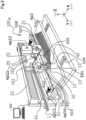
- Fig. 1 illustrates a perspective view of an entire fiber placement device 100 according to one embodiment of the present disclosure.
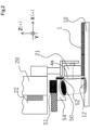
- Fig. 2 illustrates a state where a heating mechanism 50 and a tow arranging mechanism 20 are seen from a Y axis + (plus) side in Fig. 1 .
- Fig. 2 illustrates a positional relationship between the heating mechanism 50 and the tow arranging mechanism 20 of the fiber placement device 100 illustrated in Fig. 1 .
- embodiments of the fiber placement device 100 illustrated in Figs. 1 and 2 are examples, and a configuration of the fiber placement device is by no means limited by each embodiment in the present disclosure.
- the fiber placement device 100 includes: a placement base 10 which includes a placement plane 10s on which a reinforcing fiber tow 1 is placed and stacked; the tow arranging mechanism 20 which can press and place the reinforcing fiber tow 1 against and on the placement plane 10s; a tow cutting mechanism 40 which is positioned independently from the tow arranging mechanism 20, and cuts the reinforcing fiber tow 1 when a tow pressing mechanism 21 provided inside the tow arranging mechanism 20 presses the reinforcing fiber tow 1 against a blade tip; the heating mechanism 50 which is positioned independently from the tow arranging mechanism 20 and the tow cutting mechanism 40, and can heat the placement plane 10s; and a control unit 60 which monitors a state of each of the above-described mechanisms, and controls an operation of each device according to a program given by a user to place and stack the reinforcing fiber tow 1 in a desired shape on the placement plane 10s.
- a placement base 10 which includes a placement plane 10s on which a reinforcing
- the fiber placement device 100 repeatedly performs a placement cycle described below.
- the fiber placement device 100 moves the tow arranging mechanism 20 to a predetermined position. More specifically, the tow arranging mechanism 20 is moved onto the placement plane 10s heated in advance by the heating mechanism 50.
- the fiber placement device 100 presses the reinforcing fiber tow 1 fed from the tow arranging mechanism 20 onto the placement plane 10s, and then moves the tow arranging mechanism 20 by a predetermined length in a first axial direction (a Y axis direction in Fig. 1 ).
- the fiber placement device 100 moves the placement base 10 in a second axial direction (an X axis direction in Fig. 1 ) which intersects the first axial direction.
- the fiber placement device 100 repeatedly performs the above-described placement cycle. A specific configuration and operation of the fiber placement device 100 will be described below.
- the reinforcing fiber tow 1 is a unidirectional fiber fabric which includes at least reinforcing fibers and a resin component which exhibits adhesiveness when heated.
- Various material and forms of the reinforcing fiber tow 1 can be selected according to operability during an operation or required characteristics after molding.
- the materials of reinforcing fibers carbon fibers, glass fibers, aramid, Kevlar and natural fibers can be used.
- the materials of the resin component a thermosetting epoxy or phenol resin, or thermoplastic polyamide, polyether ether ketone, polyether ketone ketone, and polyether sulfone can be used.
- a mixed state of the resin component with respect to the reinforcing fiber is not limited in particular.
- a liquid resin component may be impregnated inside a reinforcing fiber tow.
- the resin component may be applied as a thin film to a tow surface. Powder resin components may adhere to a tow surface.
- the placement base 10 includes the placement plane 10s on which the reinforcing fiber tow 1 is placed and stacked.
- the placement base 10 is configured to relatively move in the X axis direction with respect to the tow arranging mechanism 20.
- the placement base 10 includes the placement plane 10s on which the reinforcing fiber tow 1 is aligned in a desired circumferential shape and placed.
- the placement base 10 includes a placement plane moving mechanism 13. After the tow arranging mechanism 20 places the reinforcing fiber tow 1 on the placement plane 10s in the above-described placement cycle, the placement plane moving mechanism 13 relatively moves the placement base 10 in the X axis direction with respect to the tow arranging mechanism.
- a placement cycle for the second and subsequent layers is performed regarding that the reinforcing fiber tow 1 of the first layer is also included in the placement plane 10s.
- the placement base 10, the tow arranging mechanism 20 and the heating mechanism 50 may be configured to be relatively movable in the X axis direction in the placement cycle.
- the placement plane moving mechanism 13 does not necessarily need to be equipped to the placement base 10, and for example, the placement base 10 may be fixed, and the tow arranging mechanism 20, the tow cutting mechanism 40 and the heating mechanism 50 may be each configured to be movable in the X axis direction.
- the tow arranging mechanism 20 can feed the reinforcing fiber tow 1 while pressing the reinforcing fiber tow 1 against the placement plane 10s, and place the reinforcing fiber tow 1 on the placement plane 10s along the Y axis direction.
- the tow arranging mechanism 20 is configured to relatively move in the X axis direction with respect to the placement base 10.
- the tow arranging mechanism 20 is attached to a slider mechanism 22 which is movable in the Y axis direction (see an arrow Ap 11 in Fig. 1 ).
- the slider mechanism 22 moves in a - (minus) direction of a Y axis
- the tow arranging mechanism 20 is moved to an upper side of a desired tow placement start position in the Y axis direction.
- the reinforcing fiber tow 1 is nipped by a nip part 102 equipped to the tow arranging mechanism 20 via a nip roller 101 equipped to the tow arranging mechanism 20 likewise.
- a distal end of the reinforcing fiber tow 1 is guided to a lower part to the tow pressing mechanism 21 by a final guide 23 provided to the tow arranging mechanism 20.
- movement of the tow arranging mechanism 20 in the - (minus) direction of the Y axis causes a necessary amount of the reinforcing fiber tow 1 for placement in the current placement cycle to be pulled out from an unillustrated tow feeding part in an upstream.
- the tow pressing mechanism 21 When the tow pressing mechanism 21 subsequently descends in a - (minus) direction of a Z axis, and approaches the placement plane 10s, the end part of the reinforcing fiber tow 1 is pressed against a tow placement start position on the placement plane 10s (see an arrow Ap12 in Fig. 1 ).
- the tow placement start position on the placement plane 10s and a placement scheduled area 11 in the current placement cycle are heated in advance by the heating mechanism 50.
- the resin component included in the reinforcing fiber tow 1 pressed against the tow placement start position of the placement plane 10s and the placement scheduled area 11 is heated, then softens, and exhibits adhesiveness.
- the reinforcing fiber tow 1 pressed against the placement plane 10s is glued and fixed to the placement plane 10s thanks to the adhesiveness.
- the reinforcing fiber tow 1 pulled out from the tow feeding part is sequentially pressed against the placement plane 10s, and glued and fixed onto the placement plane 10s (see the arrow Ap11 in Fig. 1 ).
- the placement scheduled area 11 in which the reinforcing fiber tow 1 is scheduled to be placed has already been heated by the heating mechanism 50 as described above.
- the tow arranging mechanism 20 is moved at a high speed, it is possible to reliably glue and fix the reinforcing fiber tow 1 onto the placement plane 10s.
- the tow cutting mechanism 40 includes a cutting blade 42 which cuts the reinforcing fiber tow 1.
- the tow cutting mechanism 40 is configured to be movable in the Y axis direction and a Z axis direction (see arrows Ap13 and Ap14 in Fig. 1 ).
- the cutting blade 42 of the tow cutting mechanism 40 attached to the slider mechanism 41 cuts the reinforcing fiber tow 1.
- the slider mechanism 41 is configured to be movable in the Y axis direction independently from the slider mechanism 22 (see the arrow Ap13 in Fig. 1 ).
- the tow pressing mechanism 21 and the tow cutting mechanism 40 ascend in a + (plus) direction of the Z axis, and evacuates from the placement plane 10s (see the arrows Ap12 and A14 in Fig. 1 ).
- the placement base 10 is moved in a + (plus) direction of an X axis along the placement plane moving mechanism 13 (see an arrow Ap2 in Fig. 1 ).
- the fiber placement device 100 can place the reinforcing fiber tow 1 in the desired two-dimensional shape on the placement plane 10s.
- the heating mechanism 50 can heat part of an area of the placement plane 10s.
- the heating mechanism 50 is configured to relatively move in the X axis direction with respect to the placement base 10. More specifically, the heating mechanism 50 is configured to be relatively movable along the second axial direction (the X axis direction in Fig. 1 ) with respect to the placement plane 10s of the placement base 10.
- the heating mechanism 50 includes a moving mechanism 51, a temperature measuring unit 52, a heater 53 and a heater housing 54.
- a heating system of the heater 53 of the heating mechanism 50 can be freely selected from systems which can heat a heating target without contacting the heating target such as a convective heating system which uses hot wind or a radiation heating system which uses an infrared ray, a lamp or a laser beam.
- the heating system of the heater 53 of the heating mechanism 50 is radiation heating which uses an infrared ray.
- the output density of the heater 53 of the heating mechanism 50 is preferably 1 W/mm 2 .
- the heater 53 whose output density is 1 W/mm 2 or less is easy to obtain.
- the heater housing 54 which grips the heater 53 preferably adopts a structure which can reflect an infrared ray radiated from the heating mechanism 50 and radiate the infrared ray only in one single direction. According to this aspect, it is possible to increase the output density of the heating mechanism 50.
- a cross-sectional shape of the heater housing 54 is an arch shape for heating only a side directly below.
- the moving mechanism 51 grips the heating mechanism 50 to move to a desired position on the placement plane 10s.
- the moving mechanism 51 can move the heating mechanism 50 in the X axis direction with respect to the placement plane 10s independently from the tow arranging mechanism 20. Consequently, it is possible to finely adjust a heating target area in the X axis direction.
- a system of the moving mechanism 51 can be freely selected from a robot arm, a gantry crane or a parallel link.
- the moving mechanism 51 may be, for example, a slider mechanism which extends from the slider mechanism 22 which moves the tow arranging mechanism 20.
- the moving mechanism 51 preferably has sufficient support rigidity by taking the weight and an inertia of the heating mechanism 50 into account. According to this aspect, it is possible to reliably place the heater 53 in the placement scheduled area on the placement plane 10s in a next placement cycle.
- the temperature measuring unit 52 measures a temperature of the placement plane 10s heated by the heater 53.
- Fig. 2 illustrates an arrow As which is directed from the temperature measuring unit 52 to the placement plane 10s whose temperature is measured by the temperature measuring unit 52.
- the temperature measuring unit 52 is preferably able to measure the temperature without contacting the placement plane 10s.
- Such a system includes radiation temperature measurement or thermography which uses infrared rays, or optical measurement.
- the temperature measuring unit 52 is preferably able to measure a temperature range of 0°C to 500°C according to a temperature range which can be heated.
- a response speed related to temperature measurement is preferably higher so as to be able to appropriately manage the temperature of the placement plane 10s even when the output density of the heater 53 is high. More specifically, the response speed is preferably 0.0001 second to 1 second.
- the control unit 60 controls the fiber placement device 100.
- the control unit 60 is a computer which includes a CPU which is a processor, a RAM and a ROM.
- the RAM includes a main memory and an auxiliary storage device.
- the CPU of the control unit 60 causes the fiber placement device 100 to operate by loading a computer program stored in the auxiliary storage device and executing the computer program.
- the control unit 60 can repeatedly perform the above placement cycle.
- the placement cycle includes first processing and second processing.
- the first processing is processing where the tow arranging mechanism 20 places the reinforcing fiber tow 1 of a predetermined length on the placement plane 10s along the Y axis direction (see the arrow Ap11 in Fig. 1 ).
- the second processing is processing of relatively moving the placement base 10 in the X axis direction with respect to the tow arranging mechanism 20 (see the arrow Ap22 in Fig. 1 ).
- the control unit 60 causes the heating mechanism 50 to heat a placement scheduled area 12 in which the reinforcing fiber tow 1 is placed in the n th placement cycle until the ( n -1)th placement cycle is finished.
- control unit 60 causes the heating mechanism 50 to move above the area in which the reinforcing fiber tow 1 is placed in the nth ( n is a natural number equal to or more than two) placement cycle and heat an area which faces the heating mechanism 50 until the ( n -1)th placement cycle is finished.
- the moving mechanism 51 equipped to the heating mechanism 50 is movable in the X axis direction independently from the slider mechanisms 22 and 41. As a result, the heating mechanism 50 is relatively movable in the X axis direction with respect to the tow arranging mechanism 20.
- the heating mechanism 50 is controlled to be located on a - (minus) side of the X axis direction with respect to the tow pressing mechanism 21 equipped to the tow arranging mechanism 20.
- the temperature measuring unit 52 measures the temperature of the area on the placement plane 10s heated by the heating mechanism 50.
- the heating mechanism 50 moves to the upper side of the placement scheduled area 12 in which the reinforcing fiber tow 1 is placed after the placement scheduled area 11, and heats the placement scheduled area 12 in advance.
- the placement scheduled area 12 is heated to a predetermined temperature. Consequently, it is possible to start the placement cycle for the placement scheduled area 12 without waiting for a rise of the temperature of the placement scheduled area 12.
- the above-described placement cycle is repeated until the reinforcing fiber tow is placed to form the two-dimensional shape having the desired circumferential shape input to the control unit 60.
- a heating mechanism is mounted on a tow arranging mechanism.
- the heating mechanism is configured to heat a tow pressing mechanism, a reinforcing fiber tow guided to the tow pressing mechanism, and part of a placement plane in a traveling direction of the tow arranging mechanism.
- heating for pasting the reinforcing fiber tow on the placement plane is performed during a placement cycle for this area.
- an initial heating standby time for heating the placement plane such that an end part of the reinforcing fiber tow is pasted on the placement plane is required at a time of start of an arranging operation.
- a continuous heating standby time for heating the placement plane prior to placement of the reinforcing fiber tow is required during the arranging operation.
- a slider mechanism which moves the tow arranging mechanism can move only at a low speed to match with the continuous heating standby time. Furthermore, at a beginning of placement of the reinforcing fiber tow, the slider mechanism needs to start movement at a very low speed to match with the initial heating standby time. As a result, a tact time required for the placement cycle increases.
- the fiber placement device 100 heats in advance the placement scheduled area of the reinforcing fiber tow in the current placement cycle. Consequently, it is possible to place the reinforcing fiber tow without the above-described initial heating standby time and continuous heating standby time, and make a speed of the placement cycle higher.
- the heating mechanism 50 which has been moved to the area in which the reinforcing fiber tow is placed in the nth placement cycle preferably heats in advance an entire area in which the reinforcing fiber tow in the nth placement cycle is placed to make a speed of the placement cycle higher.
- the area which is defined by the width and the length of the reinforcing fiber tow which can be placed on the placement plane 10s in one placement cycle by the tow arranging mechanism 20 can preferably include an area in which the heating mechanism 50 can simultaneously heat the placement plane 10s.
- a maximum width of the reinforcing fiber tow which can be placed on the placement plane 10s in one placement cycle by the tow arranging mechanism 20 will be referred to as a "maximum placement width”.
- a maximum length of the reinforcing fiber tow which can be placed on the placement plane 10s in one placement cycle by the tow arranging mechanism 20 will be referred to as a "maximum placement length”.
- the area which can be heated by the heating mechanism 50 simultaneously in the placement plane 10s will be referred to as a "heatable area”.
- AY axis direction dimension of the heatable area preferably matches with the maximum placement length.
- An X axis direction dimension of the heatable area is preferably approximately 1 to 10 times as large as the maximum placement width. According to such an aspect, it is possible to heat a placement scheduled area in a next cycle of a currently executed placement cycle and, in addition, the placement scheduled area of a subsequent placement cycle. In this regard, increasing the heatable area causes an increase in cost of the fiber placement device, and makes the components other than the heating mechanism in the fiber placement device difficult. Consequently, the X axis direction dimension of the heatable area is preferably five times as large as or equal to or less than the maximum placement width.
- the heating mechanism 50 preferably heats in advance the area in which the reinforcing fiber tow 1 is placed in the nth placement cycle while the ( n -1)th placement cycle is performed. More specifically, at least while the tow arranging mechanism 20 performs the placement cycle for the placement scheduled area 11, the heating mechanism 50 preferably heats the next placement scheduled area 12. According to this aspect, it is possible to reduce a time taken from heating to placement of the reinforcing fiber tow 1. Consequently, it is possible to increase energy use efficiency. As a result, it is possible to reduce cost required for placement of a reinforcing fiber tow.
- An aspect where heating the placement scheduled area 12 is finished before the placement cycle for the placement scheduled area 11 is performed, and the placement scheduled area 12 is not heated while the placement cycle for the placement scheduled area 11 is performed has a following task.
- Heat given to the placement scheduled area 12 is radiated by heat conduction into the placement plane 10s, and convection and radiation to surrounding environment. While a heat radiation amount differs according to a temperature difference from surroundings or a heat quantity and a thermal conductivity of the placement plane 10s, part of energy required for heating is lost due to heat radiation in any aspect.
- the placement scheduled area 12 is preferably heated until the placement cycle for the last placement scheduled area 11 is performed.
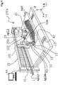
- Fig. 3 is a perspective view of an entire fiber placement device 100a according to a modified example of the first embodiment.
- the fiber placement device 100a according to this modified example includes a heating mechanism 50a instead of the heating mechanism 50 equipped to the fiber placement device 100 according to the above first embodiment.
- Other points of a hardware configuration of the fiber placement device 100a are the same as those of the fiber placement device 100.
- the heating mechanism 50a includes eight heating devices 501 to 508 placed along the Y axis direction.
- the heating devices 501 to 508 each include the heater 53.
- the heating devices 501 to 508 each include the temperature measuring unit 52, and can control feedback of a heating target temperature.
- the heating devices 501 to 508 can be each independently controlled. More specifically, on/off and output of the heating devices 501 to 508 can be independently controlled.
- the control unit 60 sets a higher temperature to a heating device which heats an area in which the reinforcing fiber tow 1 is lastly placed in the nth placement cycle among the heating devices 501 to 508 to a temperature of a heating device which heats an area in which the reinforcing fiber tow 1 is firstly placed in the nth placement cycle among the heating devices 501 to 508. More specifically, a setting temperature of the heating device which heats the area in which the reinforcing fiber tow 1 is firstly placed is set as the lowest temperature among the heating devices 501 to 508. The setting temperature of the heating device which heats the area in which the reinforcing fiber tow 1 is lastly placed is set as the lowest temperature among the heating devices 501 to 508.
- a higher setting temperature of each heating device located between these two heating devices is set to each heating device closer to the heating device which heats the area in which the reinforcing fiber tow 1 is lastly placed.
- the heating device which heats the area in which the reinforcing fiber tow 1 is firstly placed is the heating device 503
- the heating device which heats the area in which the reinforcing fiber tow 1 is lastly placed is the heating device 508.
- a shape of a reinforcing fiber sheet formed by the fiber placement device is similar to a final shape of a product, and therefore there is often a case where the length of the reinforcing fiber tow to be placed per placement cycle differs.
- the length in the Y axis direction of the reinforcing fiber tow to be placed will be also referred to as an "placement length". It is preferable to not heat a part at which the reinforcing fiber tow is not placed in the Y axis direction, and heat the part at which the reinforcing fiber tow is placed. This modified example can realize such heating.
- the heating mechanism 50a includes the eight heating devices 501 to 508.
- the number of heating devices equipped to the heating mechanism may be another number.
- the number of heating devices equipped to the heating mechanism is preferably two to ten.
- control unit 60 performs heating as described above such that an output density of the individual heating device becomes higher in order along a direction from - to + of the Y axis.
- the Y axis direction in the present embodiment will be also referred to as a "first direction”.
- the X axis direction will be also referred to as a "second direction”.
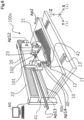
- Fig. 4 illustrates a perspective view of a fiber placement device 100b according to an embodiment different from the fiber placement device 100 according to the first embodiment.
- Fig. 5 illustrates a state where a heating mechanism 50b included in the fiber placement device 100b is seen along the Y axis direction.
- the fiber placement device 100b includes a tow arranging mechanism 20b instead of the tow arranging mechanism 20 equipped to the fiber placement device 100 according to the first embodiment.
- the fiber placement device 100b includes the heating mechanism 50b instead of the heating mechanism 50 equipped to the fiber placement device 100.
- Other points of the fiber placement device 100b are the same as those of the fiber placement device 100 according to the first embodiment.
- a configuration of the tow arranging mechanism 20b is the same as the configuration of the tow arranging mechanism 20 according to the first embodiment except that the heating mechanism 50b is attached.
- the heating mechanism 50b is provided to the tow arranging mechanism 20b.
- the heating mechanism 50b is moved along the Y axis direction together with the tow arranging mechanism 20b.
- a size of the heating mechanism 50b in the Y axis direction is configured to be small compared to the heating mechanism 50 according to the first embodiment so as not to hinder an operation of the tow arranging mechanism 20b.
- the size in the Y axis direction of the area on the placement plane 10s which the heating mechanism 50b can heat is shorter than the maximum placement length.
- the heating mechanism 50b is configured to heat part of the placement plane 10s on the Y axis direction + side seen from the tow pressing mechanism 21, and part of the area of the placement plane 10s on the X axis direction - side.
- the heating mechanism 50b heats the placement plane 10s directly below the heating mechanism 50b while the tow arranging mechanism 20 moves in the Y axis direction in the above-described placement cycle.
- the placement plane 10s directly below the heating mechanism 50b is a placement scheduled area on the X axis direction - side with respect to the reinforcing fiber tow 1 which is currently placed, and is a placement scheduled area in a next placement cycle.
- the fiber placement device 100b is suitable as a device which manufactures small parts of complicated shapes.
- Fig. 6 illustrates a perspective view of a fiber placement device 100c according to still another embodiment. Furthermore, Fig. 7 illustrates a state where a heating mechanism 50c included in the fiber placement device 100c lies along the Y axis direction.
- the fiber placement device 100c includes the heating mechanism 50c instead of the heating mechanism 50 equipped to the fiber placement device 100 according to the first embodiment. Other points of the fiber placement device 100c are the same as those of the fiber placement device 100 according to the first embodiment.
- the heating mechanism 50c is provided along the entire length in the Y axis direction of the placement plane 10s.
- the heating mechanism 50c is attached to the slider mechanism 22.
- a distance in the X axis direction between the heating mechanism 50c and the tow arranging mechanism 20 is fixed.
- the heating mechanism 50c heats an area in which the reinforcing fiber tow is placed a fixed cycle (e.g., one to five cycles) after in the area in which the tow arranging mechanism 20 in a certain placement cycle.
- the fiber placement device 100c does not include the moving mechanism 51 of the fiber placement device 100. Hence, cost of the fiber placement device 100c is low.
- a target to which the heating mechanism 50c is fixed is not limited to the slider mechanism 22.
- the heating mechanism 50c may be fixed to, for example, a frame member which supports the slider mechanism 22 or other members with a bracket interposed therebetween.
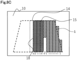
- Figs. 8A to 8C are explanatory views illustrating heating areas.
- a placement cycle is repeatedly performed to place the reinforcing fiber tow 1 on the placement plane 10s and further stack the reinforcing fiber tow 1.
- Numbers 1 to ( n +3) which indicate an order of a placement cycle of arranging reinforcing fiber tows which form the first layer are illustrated in lower parts in Figs. 8A to 8C .
- Each of Figs. 8A to 8C illustrates a state where an ( n -1)th ( n is an arbitrary integer equal to or more than two) placement cycle is being performed.
- Figs. 8A to 8C areas 14 surrounded by bold broken lines are areas in which the reinforcing fiber tows 1 are scheduled to be placed. In Figs. 8A to 8C , areas to which diagonal lines are applied are areas in which the reinforcing fiber tows 1 have already been placed. In Figs. 8A to 8C , areas 15 surrounded by thin broken lines are areas in which the reinforcing fiber tows 1 are placed in nth and subsequent placement cycles. In Figs. 8A to 8C , areas to which checkered patterns are applied are heating areas 16, 17 and 18 which are heated while the ( n -1)th ( n is an arbitrary integer equal to or more than two) placement cycle is performed.
- part of the placement scheduled area 15 in the nth and subsequent placement cycles may be heated during a ( n -k)th (k is a natural number which satisfies k ⁇ n) placement cycle
- the heating area 16 in the ( n -1)th placement cycle is configured to be across each of part of the placement scheduled areas in ( n +1)th to ( n +3)th placement cycles.
- the heating area 17 in the ( n -1)th placement cycle is an entire placement scheduled area of the ( n + 1)th to ( n +3)th placement cycles.
- the heating area 18 in the ( n -1)th placement cycle is an entire placement scheduled area of the n th to ( n +2)th placement cycles.
- the entire placement scheduled area 12 in which the reinforcing fiber tow 1 is placed in the nth placement cycle is simultaneously heated by the heating mechanism 50.
- the area in which the reinforcing fiber tow is placed in the nth placement cycle may be heated by a plurality of times of heating processing.
- the control unit 60 causes the heating mechanism 50 to heat whole area in which the reinforcing fiber tow 1 is placed in the n th placement cycle until the ( n -1)th placement cycle is finished (see Figs. 8B and 8C , too).
- the heating mechanism 50 heats part of areas in which the reinforcing fiber tow 1 is placed in the nth placement cycle until the ( n -1)th placement cycle is finished.
- the control unit 60 causes the heating mechanism 50 to heat the area in which the reinforcing fiber tow 1 is placed in the nth placement cycle during a period in which the ( n -1)th placement cycle is executed.
- the control unit 60 may cause the heating mechanism 50 to heat the area in which the reinforcing fiber tow 1 is placed in a placement cycle after the n th placement cycle during a period in which the ( n -1)th placement cycle is executed.
- the heating mechanism 50a includes the plurality of heating devices 501 to 508 which are aligned along the Y axis direction, and can be each controlled independently. Furthermore, the control unit 60 sets a higher temperature to the heating device 508 which heats the area in which the reinforcing fiber tow 1 is lastly placed in the nth placement cycle among the plurality of heating devices 501 to 508 than a temperature of the heating device 503 which heats the area in which the reinforcing fiber tow 1 is firstly placed. However, whole area in which the reinforcing fiber tow 1 is placed in the n th placement cycle may be set with an identical target temperature, and heated.
- the present disclosure is not limited to the above-described embodiments, and can be realized by various configurations without departing from the gist of the present disclosure.
- technical features in the embodiments corresponding to technical features in each aspect disclosed in the summary can be replaced or combined as appropriate to solve part or entirety of the above-described task or to achieve part or entirety of the above-described effect.
- these technical features can be deleted as appropriate if the technical features are not described as indispensable in the description.
Landscapes
- Engineering & Computer Science (AREA)
- Chemical & Material Sciences (AREA)
- Composite Materials (AREA)
- Mechanical Engineering (AREA)
- Robotics (AREA)
- Textile Engineering (AREA)
- Moulding By Coating Moulds (AREA)
- Yarns And Mechanical Finishing Of Yarns Or Ropes (AREA)
Abstract
Description
- This application is based upon and claims benefit of priority from
Japanese Patent Application No. 2020-059393, filed on March 30, 2020 - The present disclosure relates to a fiber placement device which is used to manufacture a reinforcing fiber plastic product.
- A following technique is known as a method for manufacturing a preform used to manufacture a reinforcing fiber plastic product and having a three-dimensional shape, and formed by reinforcing fibers such as glass fibers or carbon fibers. According to this technique, a cut pattern having a two-dimensional shape matching a shape of a preform of interest is cut out first from a belt-like woven fabric formed by reinforcing fibers. This cut pattern is pressed to form the preform having a three-dimensional shape. However, according to this method, the woven fabric left after the cut pattern is cut out from the belt-like woven fabric is discarded. Hence, this method has a problem that a yield rate of reinforcing fibers is poor, and manufacturing cost is high.
- As one of methods for solving this problem, a fiber placement method is known. According to the fiber placement method, a plurality of reinforcing fiber tows are placed only at a necessary place on a table to form a two-dimensional shape matching a shape of a preform of interest, and are bonded to each other. The reinforcing fiber tows placed in the two-dimensional shape in this way are pressed to manufacture the preform having the three-dimensional shape.
- For example,
Patent Literature 1 discloses a fiber placement device which can place a reinforcing fiber tow on a table at a high speed by using this method. This device includes a tow pressing mechanism which can press the reinforcing fiber tow against the table, a tow supply mechanism which can supply the reinforcing fiber tow to the table, and a cutting blade which is positioned independently from this tow supply mechanism, and is able to cut the reinforcing fiber tow when the above tow pressing mechanism presses the reinforcing fiber tow against a blade tip. By using this device, it is possible to place the reinforcing fiber tow in a desired two-dimensional shape on the table. Consequently, the yield rate of the reinforcing fibers is improved. Furthermore, this device can cut the reinforcing fiber tow without decelerating traveling of the tow supply mechanism. Consequently, the reinforcing fiber tow is placed at a higher speed. - For example,
Patent Literature 2 discloses a following device as a technique which further stacks a reinforcing fiber tow on the placed reinforcing fiber tow. This device presses a reinforcing fiber fabric to which a binder has adhered against a reinforcing fiber fabric layer stacked on a preform molding jig, or against the preform molding jig, by a heating/pressurizing roller. While this heating/pressurizing roller presses the reinforcing fiber fabric, the binder melts and glues the reinforcing fiber fabric. - For example,
Patent Literature 3 discloses a following device as a technique which secures a heating time of a binder included in a reinforcing fiber fabric which is being placed. This device includes a pressurizing roller which presses the reinforcing fiber tow against a stacking jig. This device preheats part of an area of the stacking jig in a traveling direction of the pressurizing roller in addition to the reinforcing fiber tow on an upstream side of the pressurizing roller. By using this device, it is possible to heat in advance the area in which the reinforcing fiber tow is placed. As a result, by arranging the reinforcing fiber tow in the preheated area, it is possible to soften or melt the binder by heating in a relatively short time, and reduce a tact time required to manufacture preforms. -
- Patent Literature 1:
WO 2016/047141 - Patent Literature 2:
JP 2011-57767 A - Patent Literature 3:
WO 2016/146902 - The device disclosed in
Patent Literature 1 uses a suction table as means for fixing the reinforcing fiber tow onto the table. Hence, the reinforcing fiber tow in direct contact with this suction table is fixed onto the suction table. However, when a reinforcing fiber tow is further overlaid and placed in the area in which the reinforcing fiber tow has already been placed on the suction table, the reinforcing fiber tow cannot be fixed onto the suction table. Hence, following processing is necessary to obtain a preform in which a plurality of reinforcing fiber tows are stacked by using the above device. That is, after a group of reinforcing fiber tows corresponding to one layer is placed in a two-dimensional shape matching a preform to be generated, this group of reinforcing fiber tows is transported to another stacking table. Furthermore, this group of reinforcing fiber tows is further stacked on groups of reinforcing fiber tows corresponding to a plurality of layers which have already been stacked on the stacking table. This processing is performed, and therefore the technique according toPatent Literature 1 has a problem that a tact time taken to manufacture a preform is long and manufacturing cost increases. - Furthermore, to glue the reinforcing fiber fabric by using the device disclosed in
Patent Literature 2, it is necessary to heat powder-binders in the reinforcing fiber fabric to a melting point while the heating/pressurizing roller and the reinforcing fiber fabrics guided to the heating/pressurizing roller are in contact. Therefore, it is necessary to secure a sufficiently long contact time of the heating/pressurizing roller and the reinforcing fiber fabrics. Therefore, a speed to place the reinforcing fiber fabrics is restricted, and a tact time taken to manufacture preforms becomes long. - A heating mechanism which preheats the stacking jig is mounted on a placement head including the pressurizing roller in the device disclosed in
Patent Literature 3. Furthermore, the area preheated by the heating mechanism is limited to an area in the traveling direction of the pressurizing roller. Therefore, it has been similarly impossible to set a higher speed for arranging reinforcing fiber tow to sufficiently heat the area in the traveling direction of the pressurizing roller. As a result, a reduction effect of the tact time taken to manufacture preforms has been limited. - A subject of the present disclosure is to place a reinforcing fiber tow at a higher speed and reduce a time required to manufacture preforms by reducing a heating standby time for melting or softening a binder.
- The present disclosure has been made to handle at least part of the above-described task, and can be realized as following aspects.
- (1) One aspect of the present disclosure provides a fiber placement device. This fiber placement device includes: a placement base which includes a placement plane on which a reinforcing fiber tow is placed and stacked; a tow arranging mechanism which is configured to feed the reinforcing fiber tow while pressing the reinforcing fiber tow against the placement plane, and place the reinforcing fiber tow on the placement plane along a first direction; a heating mechanism which is configured to heat part of an area of the placement plane; and a control unit which controls the fiber placement device. The placement base and the tow arranging mechanism are configured to relatively move in a second direction which intersects the first direction. The placement base and the heating mechanism are configured to relatively move in the second direction. The control unit is configured to repeatedly perform a placement cycle. The placement cycle includes first processing of causing the tow arranging mechanism to place the reinforcing fiber tow of a predetermined length on the placement plane along the first direction, and second processing of relatively moving the placement base in the second direction with respect to the tow arranging mechanism. The control unit causes the heating mechanism to heat at least part of an area in which the reinforcing fiber tow is placed in an nth (n is a natural number equal to or more than two) placement cycle until an (n -1)th placement cycle is finished.
- (2) The fiber placement device according to the above aspect can achieve an aspect where the control unit causes the heating mechanism to heat whole area in which the reinforcing fiber tow is placed in the nth placement cycle until the (n -1)th placement cycle is finished.
- (3) The fiber placement device according to the above aspect can achieve an aspect where the control unit causes the heating mechanism to heat at least the part of the area in which the reinforcing fiber tow is placed in the nth placement cycle during a period in which the (n -1)th placement cycle is executed.
- (4) The fiber placement device according to the above aspect can achieve an aspect where the heating mechanism includes a plurality of heating devices which are placed along the first direction and configured to be each independently controlled, and the control unit sets a higher temperature to a heating device which heats an area in which the reinforcing fiber tow is lastly placed in the nth placement cycle among the plurality of heating devices than a temperature of a heating device which heats an area in which the reinforcing fiber tow is firstly placed in the nth placement cycle among the plurality of heating devices.
- The fiber placement device according to the present disclosure employs following configurations (1) to (4) to handle the above task.
- (1) The fiber placement device includes at least: a placement plane on which a reinforcing fiber tow is placed and stacked; a tow arranging mechanism which presses and places the reinforcing fiber tow against and on the placement plane; and a heating mechanism which partially heats the placement plane, and can move the tow arranging mechanism to a predetermined position, cause the tow arranging mechanism to move by a predetermined length in a first axial direction after the tow arranging mechanism presses the reinforcing fiber tow against the placement plane heated in advance by the heating mechanism, and repeatedly perform a placement cycle of moving the placement plane in a second axial direction which intersects the first axial direction after gluing and fixing the reinforcing fiber tow onto the placement plane, the heating mechanism is configured to be relatively movable along the second axial direction with respect to the placement plane, and the heating mechanism is moved to an upper side of an area in which the reinforcing fiber tow is placed in an nth (n is the natural number equal to or more than two) placement cycle until an (n -1)th placement cycle is finished to heat the area in advance.
- (2) According to the fiber placement device described in (1), the heating mechanism moved to the area in which the reinforcing fiber tow is placed in the nth placement cycle heats in advance an entire area in which the reinforcing fiber tow is placed in the nth placement cycle.
- (3) According to the fiber placement device described in (1) or (2), the heating mechanism moved to the area in which the reinforcing fiber tow is placed in the nth placement cycle heats in advance the area in which the reinforcing fiber tow is placed in the nth placement cycle while the (n -1)th placement cycle is performed.
- (4) According to the fiber placement device described in any one of (1) to (3), the heating mechanism includes a group of heating devices which are divided into a plurality of areas along the first axial direction, and the group of the heating devices is configured to independently adjust a heating state.
- The present disclosure can be also realized as various aspects other than the fiber placement device. The present disclosure can be realized as aspects such as a fiber placement device manufacturing method, a fiber placement device control method, a computer program which realizes this fiber placement device control method and a non-transitory recording medium having this computer program recorded thereon.
- By using the fiber placement device according to the present disclosure, it is possible to separately perform heating processing for melting or softening of binders included in reinforcing fiber tows, and a placement operation of the tow arranging mechanism. Consequently, it is possible to place and stack the reinforcing fibers tow on a placement plane at a high speed irrespectively of a heating standby time of the binders.
-
-
Fig. 1 is a perspective view illustrating an entirefiber placement device 100 according to one embodiment of the present disclosure. -
Fig. 2 is a Y axis direction perspective view for explaining an operation of aheating mechanism 50 of thefiber placement device 100 according to one embodiment of the present disclosure. -
Fig. 3 is a perspective view of an entire fiber placement device 100a according to a modified example of the first embodiment. -
Fig. 4 is a perspective view illustrating an entirefiber placement device 100b according to one embodiment of the present disclosure. -
Fig. 5 is an explanatory view illustrating a state where aheating mechanism 50b included in afiber placement device 100c lies along a Y axis direction. -
Fig. 6 is an explanatory view for explaining an operation of theheating mechanism 50c of thefiber placement device 100c according to one embodiment of the present disclosure. -
Fig. 7 is an explanatory view illustrating a state where theheating mechanism 50c included in afiber placement device 100c lies along the Y axis direction. -
Fig. 8A is an explanatory view for explaining a positional relationship between a placement cycle of a tow arranging mechanism and a heating area of a heating mechanism according to one embodiment of the present disclosure. -
Fig. 8B is an explanatory view for explaining a positional relationship between the placement cycle of the tow arranging mechanism and the heating area of the heating mechanism according to one embodiment of the present disclosure. -
Fig. 8C is an explanatory view for explaining a positional relationship between the placement cycle of the tow arranging mechanism and the heating area of the heating mechanism according to one embodiment of the present disclosure. - Specific embodiments of the present disclosure will be described below with reference to the drawings. Note that the following description facilitates understanding of the present disclosure, and by no means limits the present disclosure. In this regard, as is readily understood by one of ordinary skill in the art, motions to preferred aspects and variations in individual embodiments can be simultaneously interpreted as explanation of a fiber placement device which is a generic concept of the present disclosure.
- The fiber placement device according to the present disclosure includes at least: a placement plane on which a reinforcing fiber tow is placed and stacked; a tow arranging mechanism which presses and places the reinforcing fiber tow against and on the placement plane; and a heating mechanism which partially heats the placement plane, and can move the tow arranging mechanism to a predetermined position, cause the tow arranging mechanism to move by a predetermined length in a first axial direction after the tow arranging mechanism presses the reinforcing fiber tow against the placement plane heated in advance by the heating mechanism, and repeatedly perform a placement cycle of moving the placement plane in a second axial direction which intersects the first axial direction after gluing and fixing the reinforcing fiber tow onto the placement plane, the heating mechanism is configured to be relatively movable along the second axial direction with respect to the placement plane, and the heating mechanism is moved to an upper side of an area in which the reinforcing fiber tow is placed in an nth (n is the natural number equal to or more than two) placement cycle until an (n -1)th placement cycle is finished to heat the area in advance.
-
Fig. 1 illustrates a perspective view of an entirefiber placement device 100 according to one embodiment of the present disclosure.Fig. 2 illustrates a state where aheating mechanism 50 and atow arranging mechanism 20 are seen from a Y axis + (plus) side inFig. 1 .Fig. 2 illustrates a positional relationship between theheating mechanism 50 and thetow arranging mechanism 20 of thefiber placement device 100 illustrated inFig. 1 . Note that embodiments of thefiber placement device 100 illustrated inFigs. 1 and2 are examples, and a configuration of the fiber placement device is by no means limited by each embodiment in the present disclosure. - In the present embodiment, the
fiber placement device 100 includes: aplacement base 10 which includes aplacement plane 10s on which a reinforcingfiber tow 1 is placed and stacked; thetow arranging mechanism 20 which can press and place the reinforcingfiber tow 1 against and on theplacement plane 10s; atow cutting mechanism 40 which is positioned independently from thetow arranging mechanism 20, and cuts the reinforcingfiber tow 1 when a towpressing mechanism 21 provided inside thetow arranging mechanism 20 presses the reinforcingfiber tow 1 against a blade tip; theheating mechanism 50 which is positioned independently from thetow arranging mechanism 20 and thetow cutting mechanism 40, and can heat theplacement plane 10s; and acontrol unit 60 which monitors a state of each of the above-described mechanisms, and controls an operation of each device according to a program given by a user to place and stack the reinforcingfiber tow 1 in a desired shape on theplacement plane 10s. - In the present disclosure, the
fiber placement device 100 repeatedly performs a placement cycle described below. First, thefiber placement device 100 moves thetow arranging mechanism 20 to a predetermined position. More specifically, thetow arranging mechanism 20 is moved onto theplacement plane 10s heated in advance by theheating mechanism 50. Thefiber placement device 100 presses the reinforcingfiber tow 1 fed from thetow arranging mechanism 20 onto theplacement plane 10s, and then moves thetow arranging mechanism 20 by a predetermined length in a first axial direction (a Y axis direction inFig. 1 ). After the reinforcingfiber tow 1 is glued onto theplacement plane 10s and thereby fixed, thefiber placement device 100 moves theplacement base 10 in a second axial direction (an X axis direction inFig. 1 ) which intersects the first axial direction. Thefiber placement device 100 repeatedly performs the above-described placement cycle. A specific configuration and operation of thefiber placement device 100 will be described below. - The reinforcing
fiber tow 1 is a unidirectional fiber fabric which includes at least reinforcing fibers and a resin component which exhibits adhesiveness when heated. Various material and forms of the reinforcingfiber tow 1 can be selected according to operability during an operation or required characteristics after molding. For example, as the materials of reinforcing fibers, carbon fibers, glass fibers, aramid, Kevlar and natural fibers can be used. As the materials of the resin component, a thermosetting epoxy or phenol resin, or thermoplastic polyamide, polyether ether ketone, polyether ketone ketone, and polyether sulfone can be used. Furthermore, a mixed state of the resin component with respect to the reinforcing fiber is not limited in particular. A liquid resin component may be impregnated inside a reinforcing fiber tow. The resin component may be applied as a thin film to a tow surface. Powder resin components may adhere to a tow surface. - The
placement base 10 includes theplacement plane 10s on which the reinforcingfiber tow 1 is placed and stacked. Theplacement base 10 is configured to relatively move in the X axis direction with respect to thetow arranging mechanism 20. - More specifically, the
placement base 10 includes theplacement plane 10s on which the reinforcingfiber tow 1 is aligned in a desired circumferential shape and placed. Theplacement base 10 includes a placementplane moving mechanism 13. After thetow arranging mechanism 20 places the reinforcingfiber tow 1 on theplacement plane 10s in the above-described placement cycle, the placementplane moving mechanism 13 relatively moves theplacement base 10 in the X axis direction with respect to the tow arranging mechanism. Furthermore, in a case where the reinforcingfiber tow 1 is placed in the desired circumferential shape, and then the reinforcingfiber tows 1 of second and subsequent layers are placed and stacked overlapping thereon, a placement cycle for the second and subsequent layers is performed regarding that the reinforcingfiber tow 1 of the first layer is also included in theplacement plane 10s. - Note that the
placement base 10, thetow arranging mechanism 20 and theheating mechanism 50 may be configured to be relatively movable in the X axis direction in the placement cycle. Hence, the placementplane moving mechanism 13 does not necessarily need to be equipped to theplacement base 10, and for example, theplacement base 10 may be fixed, and thetow arranging mechanism 20, thetow cutting mechanism 40 and theheating mechanism 50 may be each configured to be movable in the X axis direction. - The
tow arranging mechanism 20 can feed the reinforcingfiber tow 1 while pressing the reinforcingfiber tow 1 against theplacement plane 10s, and place the reinforcingfiber tow 1 on theplacement plane 10s along the Y axis direction. Thetow arranging mechanism 20 is configured to relatively move in the X axis direction with respect to theplacement base 10. - More specifically, the
tow arranging mechanism 20 is attached to aslider mechanism 22 which is movable in the Y axis direction (see anarrow Ap 11 inFig. 1 ). When theslider mechanism 22 moves in a - (minus) direction of a Y axis, thetow arranging mechanism 20 is moved to an upper side of a desired tow placement start position in the Y axis direction. In this case, the reinforcingfiber tow 1 is nipped by a nippart 102 equipped to thetow arranging mechanism 20 via anip roller 101 equipped to thetow arranging mechanism 20 likewise. A distal end of the reinforcingfiber tow 1 is guided to a lower part to thetow pressing mechanism 21 by afinal guide 23 provided to thetow arranging mechanism 20. Hence, movement of thetow arranging mechanism 20 in the - (minus) direction of the Y axis causes a necessary amount of the reinforcingfiber tow 1 for placement in the current placement cycle to be pulled out from an unillustrated tow feeding part in an upstream. - When the
tow pressing mechanism 21 subsequently descends in a - (minus) direction of a Z axis, and approaches theplacement plane 10s, the end part of the reinforcingfiber tow 1 is pressed against a tow placement start position on theplacement plane 10s (see an arrow Ap12 inFig. 1 ). In this case, the tow placement start position on theplacement plane 10s and a placement scheduledarea 11 in the current placement cycle are heated in advance by theheating mechanism 50. Hence, the resin component included in the reinforcingfiber tow 1 pressed against the tow placement start position of theplacement plane 10s and the placement scheduledarea 11 is heated, then softens, and exhibits adhesiveness. As a result, the reinforcingfiber tow 1 pressed against theplacement plane 10s is glued and fixed to theplacement plane 10s thanks to the adhesiveness. - When the
slider mechanism 22 moves thetow arranging mechanism 20 by a predetermined distance in a + (plus) direction of the Y axis, the reinforcingfiber tow 1 pulled out from the tow feeding part is sequentially pressed against theplacement plane 10s, and glued and fixed onto theplacement plane 10s (see the arrow Ap11 inFig. 1 ). In this case, the placement scheduledarea 11 in which the reinforcingfiber tow 1 is scheduled to be placed has already been heated by theheating mechanism 50 as described above. Hence, in order to glue the reinforcingfiber tow 1, it is not necessary to heat the placement scheduledarea 11 immediately before the reinforcingfiber tow 1 is placed. Consequently, even when thetow arranging mechanism 20 is moved at a high speed, it is possible to reliably glue and fix the reinforcingfiber tow 1 onto theplacement plane 10s. - The
tow cutting mechanism 40 includes acutting blade 42 which cuts the reinforcingfiber tow 1. Thetow cutting mechanism 40 is configured to be movable in the Y axis direction and a Z axis direction (see arrows Ap13 and Ap14 inFig. 1 ). - After the reinforcing
fiber tow 1 is placed on and fixed onto theplacement plane 10s along the Y axis direction (see the arrow Ap11 inFig. 1 ), thecutting blade 42 of thetow cutting mechanism 40 attached to theslider mechanism 41 cuts the reinforcingfiber tow 1. Theslider mechanism 41 is configured to be movable in the Y axis direction independently from the slider mechanism 22 (see the arrow Ap13 inFig. 1 ). The towpressing mechanism 21 and thetow cutting mechanism 40 ascend in a + (plus) direction of the Z axis, and evacuates from theplacement plane 10s (see the arrows Ap12 and A14 inFig. 1 ). Subsequently, theplacement base 10 is moved in a + (plus) direction of an X axis along the placement plane moving mechanism 13 (see an arrow Ap2 inFig. 1 ). - The above-described operation will be referred to as a series of the "placement cycle". By repeating this placement cycle, the
fiber placement device 100 can place the reinforcingfiber tow 1 in the desired two-dimensional shape on theplacement plane 10s. - The
heating mechanism 50 can heat part of an area of theplacement plane 10s. Theheating mechanism 50 is configured to relatively move in the X axis direction with respect to theplacement base 10. More specifically, theheating mechanism 50 is configured to be relatively movable along the second axial direction (the X axis direction inFig. 1 ) with respect to theplacement plane 10s of theplacement base 10. Theheating mechanism 50 includes a movingmechanism 51, atemperature measuring unit 52, a heater 53 and aheater housing 54. - A heating system of the heater 53 of the
heating mechanism 50 can be freely selected from systems which can heat a heating target without contacting the heating target such as a convective heating system which uses hot wind or a radiation heating system which uses an infrared ray, a lamp or a laser beam. In the present embodiment, from a viewpoint of heating output (which will be referred to as an output density below) per unit area of a target, manufacturing cost and easiness of output control, the heating system of the heater 53 of theheating mechanism 50 is radiation heating which uses an infrared ray. - A higher output density of the
heating mechanism 50 results in a higher speed of the placement cycle. On the other hand, a heater of a high output density leads to an increase in manufacturing cost of thefiber placement device 100. Hence, the output density of the heater 53 of theheating mechanism 50 is preferably 1 W/mm2. The heater 53 whose output density is 1 W/mm2 or less is easy to obtain. - The
heater housing 54 which grips the heater 53 preferably adopts a structure which can reflect an infrared ray radiated from theheating mechanism 50 and radiate the infrared ray only in one single direction. According to this aspect, it is possible to increase the output density of theheating mechanism 50. For example, a cross-sectional shape of theheater housing 54 is an arch shape for heating only a side directly below. - The moving
mechanism 51 grips theheating mechanism 50 to move to a desired position on theplacement plane 10s. The movingmechanism 51 can move theheating mechanism 50 in the X axis direction with respect to theplacement plane 10s independently from thetow arranging mechanism 20. Consequently, it is possible to finely adjust a heating target area in the X axis direction. - A system of the moving
mechanism 51 can be freely selected from a robot arm, a gantry crane or a parallel link. The movingmechanism 51 may be, for example, a slider mechanism which extends from theslider mechanism 22 which moves thetow arranging mechanism 20. Furthermore, the movingmechanism 51 preferably has sufficient support rigidity by taking the weight and an inertia of theheating mechanism 50 into account. According to this aspect, it is possible to reliably place the heater 53 in the placement scheduled area on theplacement plane 10s in a next placement cycle. - The
temperature measuring unit 52 measures a temperature of theplacement plane 10s heated by the heater 53.Fig. 2 illustrates an arrow As which is directed from thetemperature measuring unit 52 to theplacement plane 10s whose temperature is measured by thetemperature measuring unit 52. Thetemperature measuring unit 52 is preferably able to measure the temperature without contacting theplacement plane 10s. Such a system includes radiation temperature measurement or thermography which uses infrared rays, or optical measurement. Thetemperature measuring unit 52 is preferably able to measure a temperature range of 0°C to 500°C according to a temperature range which can be heated. Furthermore, a response speed related to temperature measurement is preferably higher so as to be able to appropriately manage the temperature of theplacement plane 10s even when the output density of the heater 53 is high. More specifically, the response speed is preferably 0.0001 second to 1 second. - The
control unit 60 controls thefiber placement device 100. Thecontrol unit 60 is a computer which includes a CPU which is a processor, a RAM and a ROM. The RAM includes a main memory and an auxiliary storage device. The CPU of thecontrol unit 60 causes thefiber placement device 100 to operate by loading a computer program stored in the auxiliary storage device and executing the computer program. - The
control unit 60 can repeatedly perform the above placement cycle. The placement cycle includes first processing and second processing. The first processing is processing where thetow arranging mechanism 20 places the reinforcingfiber tow 1 of a predetermined length on theplacement plane 10s along the Y axis direction (see the arrow Ap11 inFig. 1 ). The second processing is processing of relatively moving theplacement base 10 in the X axis direction with respect to the tow arranging mechanism 20 (see the arrow Ap22 inFig. 1 ). Thecontrol unit 60 causes theheating mechanism 50 to heat a placement scheduledarea 12 in which the reinforcingfiber tow 1 is placed in the nth placement cycle until the (n -1)th placement cycle is finished. - More specifically, the
control unit 60 causes theheating mechanism 50 to move above the area in which the reinforcingfiber tow 1 is placed in the nth (n is a natural number equal to or more than two) placement cycle and heat an area which faces theheating mechanism 50 until the (n -1)th placement cycle is finished. - Still more specifically, following processing is executed. The moving
mechanism 51 equipped to theheating mechanism 50 is movable in the X axis direction independently from theslider mechanisms heating mechanism 50 is relatively movable in the X axis direction with respect to thetow arranging mechanism 20. Theheating mechanism 50 is controlled to be located on a - (minus) side of the X axis direction with respect to thetow pressing mechanism 21 equipped to thetow arranging mechanism 20. Thetemperature measuring unit 52 measures the temperature of the area on theplacement plane 10s heated by theheating mechanism 50. - While or before the
tow arranging mechanism 20 performs the placement cycle for arranging the reinforcingfiber tow 1 in the placement scheduledarea 11, theheating mechanism 50 moves to the upper side of the placement scheduledarea 12 in which the reinforcingfiber tow 1 is placed after the placement scheduledarea 11, and heats the placement scheduledarea 12 in advance. By a time when the placement cycle for the placement scheduledarea 11 is finished, and the placement cycle for the placement scheduledarea 12 starts, the placement scheduledarea 12 is heated to a predetermined temperature. Consequently, it is possible to start the placement cycle for the placement scheduledarea 12 without waiting for a rise of the temperature of the placement scheduledarea 12. - Subsequently, the above-described placement cycle is repeated until the reinforcing fiber tow is placed to form the two-dimensional shape having the desired circumferential shape input to the
control unit 60. As a result, an original form of a reinforcing fiber sheet in which the plurality of reinforcingfiber tow 1 extending in the X axis direction are aligned in the Y axis direction. - In a conventional fiber placement device, a heating mechanism is mounted on a tow arranging mechanism. The heating mechanism is configured to heat a tow pressing mechanism, a reinforcing fiber tow guided to the tow pressing mechanism, and part of a placement plane in a traveling direction of the tow arranging mechanism. According to this aspect, heating for pasting the reinforcing fiber tow on the placement plane is performed during a placement cycle for this area. Hence, an initial heating standby time for heating the placement plane such that an end part of the reinforcing fiber tow is pasted on the placement plane is required at a time of start of an arranging operation. Furthermore, a continuous heating standby time for heating the placement plane prior to placement of the reinforcing fiber tow is required during the arranging operation. Hence, when the reinforcing fiber tow is placed, a slider mechanism which moves the tow arranging mechanism can move only at a low speed to match with the continuous heating standby time. Furthermore, at a beginning of placement of the reinforcing fiber tow, the slider mechanism needs to start movement at a very low speed to match with the initial heating standby time. As a result, a tact time required for the placement cycle increases.
- On the other hand, in a last placement cycle, the
fiber placement device 100 according to the present disclosure heats in advance the placement scheduled area of the reinforcing fiber tow in the current placement cycle. Consequently, it is possible to place the reinforcing fiber tow without the above-described initial heating standby time and continuous heating standby time, and make a speed of the placement cycle higher. - The
heating mechanism 50 which has been moved to the area in which the reinforcing fiber tow is placed in the nth placement cycle preferably heats in advance an entire area in which the reinforcing fiber tow in the nth placement cycle is placed to make a speed of the placement cycle higher. - More specifically, the area which is defined by the width and the length of the reinforcing fiber tow which can be placed on the
placement plane 10s in one placement cycle by thetow arranging mechanism 20 can preferably include an area in which theheating mechanism 50 can simultaneously heat theplacement plane 10s. In this description, a maximum width of the reinforcing fiber tow which can be placed on theplacement plane 10s in one placement cycle by thetow arranging mechanism 20 will be referred to as a "maximum placement width". A maximum length of the reinforcing fiber tow which can be placed on theplacement plane 10s in one placement cycle by thetow arranging mechanism 20 will be referred to as a "maximum placement length". The area which can be heated by theheating mechanism 50 simultaneously in theplacement plane 10s will be referred to as a "heatable area". - AY axis direction dimension of the heatable area preferably matches with the maximum placement length. An X axis direction dimension of the heatable area is preferably approximately 1 to 10 times as large as the maximum placement width. According to such an aspect, it is possible to heat a placement scheduled area in a next cycle of a currently executed placement cycle and, in addition, the placement scheduled area of a subsequent placement cycle. In this regard, increasing the heatable area causes an increase in cost of the fiber placement device, and makes the components other than the heating mechanism in the fiber placement device difficult. Consequently, the X axis direction dimension of the heatable area is preferably five times as large as or equal to or less than the maximum placement width.
- Furthermore, the
heating mechanism 50 preferably heats in advance the area in which the reinforcingfiber tow 1 is placed in the nth placement cycle while the (n -1)th placement cycle is performed. More specifically, at least while thetow arranging mechanism 20 performs the placement cycle for the placement scheduledarea 11, theheating mechanism 50 preferably heats the next placement scheduledarea 12. According to this aspect, it is possible to reduce a time taken from heating to placement of the reinforcingfiber tow 1. Consequently, it is possible to increase energy use efficiency. As a result, it is possible to reduce cost required for placement of a reinforcing fiber tow. - An aspect where heating the placement scheduled
area 12 is finished before the placement cycle for the placement scheduledarea 11 is performed, and the placement scheduledarea 12 is not heated while the placement cycle for the placement scheduledarea 11 is performed has a following task. Heat given to the placement scheduledarea 12 is radiated by heat conduction into theplacement plane 10s, and convection and radiation to surrounding environment. While a heat radiation amount differs according to a temperature difference from surroundings or a heat quantity and a thermal conductivity of theplacement plane 10s, part of energy required for heating is lost due to heat radiation in any aspect. To reduce cost required to place a reinforcing fiber tow, it is preferable to use energy required for heating to highly efficiently melt binders. Hence, the placement scheduledarea 12 is preferably heated until the placement cycle for the last placement scheduledarea 11 is performed. -
Fig. 3 is a perspective view of an entire fiber placement device 100a according to a modified example of the first embodiment. The fiber placement device 100a according to this modified example includes aheating mechanism 50a instead of theheating mechanism 50 equipped to thefiber placement device 100 according to the above first embodiment. Other points of a hardware configuration of the fiber placement device 100a are the same as those of thefiber placement device 100. - The
heating mechanism 50a includes eightheating devices 501 to 508 placed along the Y axis direction. Theheating devices 501 to 508 each include the heater 53. Theheating devices 501 to 508 each include thetemperature measuring unit 52, and can control feedback of a heating target temperature. Theheating devices 501 to 508 can be each independently controlled. More specifically, on/off and output of theheating devices 501 to 508 can be independently controlled. - The
control unit 60 sets a higher temperature to a heating device which heats an area in which the reinforcingfiber tow 1 is lastly placed in the nth placement cycle among theheating devices 501 to 508 to a temperature of a heating device which heats an area in which the reinforcingfiber tow 1 is firstly placed in the nth placement cycle among theheating devices 501 to 508. More specifically, a setting temperature of the heating device which heats the area in which the reinforcingfiber tow 1 is firstly placed is set as the lowest temperature among theheating devices 501 to 508. The setting temperature of the heating device which heats the area in which the reinforcingfiber tow 1 is lastly placed is set as the lowest temperature among theheating devices 501 to 508. A higher setting temperature of each heating device located between these two heating devices is set to each heating device closer to the heating device which heats the area in which the reinforcingfiber tow 1 is lastly placed. In the example inFig. 3 , the heating device which heats the area in which the reinforcingfiber tow 1 is firstly placed is theheating device 503, and the heating device which heats the area in which the reinforcingfiber tow 1 is lastly placed is theheating device 508. - A shape of a reinforcing fiber sheet formed by the fiber placement device is similar to a final shape of a product, and therefore there is often a case where the length of the reinforcing fiber tow to be placed per placement cycle differs. The length in the Y axis direction of the reinforcing fiber tow to be placed will be also referred to as an "placement length". It is preferable to not heat a part at which the reinforcing fiber tow is not placed in the Y axis direction, and heat the part at which the reinforcing fiber tow is placed. This modified example can realize such heating.
- In addition, in this modified example, the
heating mechanism 50a includes the eightheating devices 501 to 508. In this regard, the number of heating devices equipped to the heating mechanism may be another number. In this regard, the number of heating devices equipped to the heating mechanism is preferably two to ten. - In this modified example, the
control unit 60 performs heating as described above such that an output density of the individual heating device becomes higher in order along a direction from - to + of the Y axis. - In an area closer to an end on a + side of both ends in the Y axis direction of the placement scheduled
area 12, a time taken until the reinforcing fiber tow is placed after theheating mechanism 50a finishes heating becomes longer. Hence, a heat radiation amount is larger in an area closer to the end on the Y axis direction + side, and a temperature at a time when the reinforcing fiber tow is placed becomes substantially lower than a temperature at a time when heating is performed. By setting the output densities of the plurality of heating devices as described above, it is possible to give a temperature gradient which takes heat radiation into account to the placement scheduled area. As a result, it is possible to place the reinforcing fiber tow in a state where each placement scheduled area has an optimal temperature. Furthermore, excessive heating is not performed in an area closer to an end on a-side of the both ends in the Y axis direction of the placement scheduledarea 12, so that it is possible to avoid wasteful energy consumption. - The Y axis direction in the present embodiment will be also referred to as a "first direction". The X axis direction will be also referred to as a "second direction".
-
Fig. 4 illustrates a perspective view of afiber placement device 100b according to an embodiment different from thefiber placement device 100 according to the first embodiment. Furthermore,Fig. 5 illustrates a state where aheating mechanism 50b included in thefiber placement device 100b is seen along the Y axis direction. - The
fiber placement device 100b includes atow arranging mechanism 20b instead of thetow arranging mechanism 20 equipped to thefiber placement device 100 according to the first embodiment. Thefiber placement device 100b includes theheating mechanism 50b instead of theheating mechanism 50 equipped to thefiber placement device 100. Other points of thefiber placement device 100b are the same as those of thefiber placement device 100 according to the first embodiment. - A configuration of the
tow arranging mechanism 20b is the same as the configuration of thetow arranging mechanism 20 according to the first embodiment except that theheating mechanism 50b is attached. - The
heating mechanism 50b is provided to thetow arranging mechanism 20b. When thetow arranging mechanism 20b is moved along the Y axis direction by theslider mechanism 22, theheating mechanism 50b is moved along the Y axis direction together with thetow arranging mechanism 20b. According to the present embodiment, a size of theheating mechanism 50b in the Y axis direction is configured to be small compared to theheating mechanism 50 according to the first embodiment so as not to hinder an operation of thetow arranging mechanism 20b. Hence, the size in the Y axis direction of the area on theplacement plane 10s which theheating mechanism 50b can heat is shorter than the maximum placement length. Theheating mechanism 50b is configured to heat part of theplacement plane 10s on the Y axis direction + side seen from thetow pressing mechanism 21, and part of the area of theplacement plane 10s on the X axis direction - side. - The
heating mechanism 50b heats theplacement plane 10s directly below theheating mechanism 50b while thetow arranging mechanism 20 moves in the Y axis direction in the above-described placement cycle. Theplacement plane 10s directly below theheating mechanism 50b is a placement scheduled area on the X axis direction - side with respect to the reinforcingfiber tow 1 which is currently placed, and is a placement scheduled area in a next placement cycle. - According to the present embodiment, it is possible to miniaturize the
heating mechanism 50b, and reduce device cost and running cost. Furthermore, it is possible to heat a next placement scheduled area even when theplacement plane 10s has a three-dimensional shape. Consequently, thefiber placement device 100b is suitable as a device which manufactures small parts of complicated shapes. -
Fig. 6 illustrates a perspective view of afiber placement device 100c according to still another embodiment. Furthermore,Fig. 7 illustrates a state where aheating mechanism 50c included in thefiber placement device 100c lies along the Y axis direction. - The
fiber placement device 100c includes theheating mechanism 50c instead of theheating mechanism 50 equipped to thefiber placement device 100 according to the first embodiment. Other points of thefiber placement device 100c are the same as those of thefiber placement device 100 according to the first embodiment. - The
heating mechanism 50c is provided along the entire length in the Y axis direction of theplacement plane 10s. Theheating mechanism 50c is attached to theslider mechanism 22. A distance in the X axis direction between theheating mechanism 50c and thetow arranging mechanism 20 is fixed. Hence, in thisfiber placement device 100c, theheating mechanism 50c heats an area in which the reinforcing fiber tow is placed a fixed cycle (e.g., one to five cycles) after in the area in which thetow arranging mechanism 20 in a certain placement cycle. Thefiber placement device 100c does not include the movingmechanism 51 of thefiber placement device 100. Hence, cost of thefiber placement device 100c is low. - In this regard, as long as the
heating mechanism 50c is independently movable with respect to theplacement plane 10s, a target to which theheating mechanism 50c is fixed is not limited to theslider mechanism 22. Theheating mechanism 50c may be fixed to, for example, a frame member which supports theslider mechanism 22 or other members with a bracket interposed therebetween. -
Figs. 8A to 8C are explanatory views illustrating heating areas. In each of examples illustrated inFigs. 8A to 8C , a placement cycle is repeatedly performed to place the reinforcingfiber tow 1 on theplacement plane 10s and further stack the reinforcingfiber tow 1.Numbers 1 to (n +3) which indicate an order of a placement cycle of arranging reinforcing fiber tows which form the first layer are illustrated in lower parts inFigs. 8A to 8C . Each ofFigs. 8A to 8C illustrates a state where an (n -1)th (n is an arbitrary integer equal to or more than two) placement cycle is being performed. - In
Figs. 8A to 8C ,areas 14 surrounded by bold broken lines are areas in which the reinforcingfiber tows 1 are scheduled to be placed. InFigs. 8A to 8C , areas to which diagonal lines are applied are areas in which the reinforcingfiber tows 1 have already been placed. InFigs. 8A to 8C ,areas 15 surrounded by thin broken lines are areas in which the reinforcingfiber tows 1 are placed in nth and subsequent placement cycles. InFigs. 8A to 8C , areas to which checkered patterns are applied areheating areas - At one of points of time until the (n -1)th placement cycle is finished, at least part of the placement scheduled
area 15 of the reinforcing fiber tow in the nth and subsequent placement cycles is heated. - In the present disclosure, part of the placement scheduled
area 15 in the nth and subsequent placement cycles may be heated during a (n -k)th (k is a natural number which satisfies k < n) placement cycle In the example inFig. 8A , theheating area 16 in the (n -1)th placement cycle is configured to be across each of part of the placement scheduled areas in (n +1)th to (n +3)th placement cycles. - It is preferable to heat the entire placement scheduled area in advance to make a speed of the placement cycle higher. In the example in
Fig. 8B , theheating area 17 in the (n -1)th placement cycle is an entire placement scheduled area of the (n + 1)th to (n +3)th placement cycles. - It is preferable to heat the placement scheduled area of the reinforcing fiber tow in the next placement cycle to reduce energy loss due to heat radiation from the preheated area. In the example in
Fig. 8C , theheating area 18 in the (n -1)th placement cycle is an entire placement scheduled area of the nth to (n +2)th placement cycles. - According to the first embodiment, the entire placement scheduled
area 12 in which the reinforcingfiber tow 1 is placed in the nth placement cycle is simultaneously heated by theheating mechanism 50. However, the area in which the reinforcing fiber tow is placed in the nth placement cycle may be heated by a plurality of times of heating processing. - According to the above first embodiment and third embodiment, the
control unit 60 causes theheating mechanism 50 to heat whole area in which the reinforcingfiber tow 1 is placed in the nth placement cycle until the (n -1)th placement cycle is finished (seeFigs. 8B and8C , too). However, there may also be employed an aspect where, as illustrated in the example inFig. 8A , theheating mechanism 50 heats part of areas in which the reinforcingfiber tow 1 is placed in the nth placement cycle until the (n -1)th placement cycle is finished. - It is preferable to finish heating the area in which the reinforcing
fiber tow 1 is firstly placed in the nth placement cycle until the (n -1)th placement cycle is finished. That is, it is preferable to raise the temperature of the area in which the reinforcingfiber tow 1 is firstly placed in the nth placement cycle to a target temperature until the nth placement cycle is started. - In the example illustrated in
Fig. 8C , thecontrol unit 60 causes theheating mechanism 50 to heat the area in which the reinforcingfiber tow 1 is placed in the nth placement cycle during a period in which the (n -1)th placement cycle is executed. However, thecontrol unit 60 may cause theheating mechanism 50 to heat the area in which the reinforcingfiber tow 1 is placed in a placement cycle after the nth placement cycle during a period in which the (n -1)th placement cycle is executed. - According to the modified example of the above first embodiment, the
heating mechanism 50a includes the plurality ofheating devices 501 to 508 which are aligned along the Y axis direction, and can be each controlled independently. Furthermore, thecontrol unit 60 sets a higher temperature to theheating device 508 which heats the area in which the reinforcingfiber tow 1 is lastly placed in the nth placement cycle among the plurality ofheating devices 501 to 508 than a temperature of theheating device 503 which heats the area in which the reinforcingfiber tow 1 is firstly placed. However, whole area in which the reinforcingfiber tow 1 is placed in the nth placement cycle may be set with an identical target temperature, and heated. - The present disclosure is not limited to the above-described embodiments, and can be realized by various configurations without departing from the gist of the present disclosure. For example, technical features in the embodiments corresponding to technical features in each aspect disclosed in the summary can be replaced or combined as appropriate to solve part or entirety of the above-described task or to achieve part or entirety of the above-described effect. Furthermore, these technical features can be deleted as appropriate if the technical features are not described as indispensable in the description.
-
- 1
- Reinforcing fiber tow
- 2
- Reinforcing fiber
- 3
- Resin component
- 10
- Placement base
- 10s
- Placement plane
- 11
- Placement scheduled area of reinforcing fiber tow in current placement cycle
- 12
- Placement scheduled area of reinforcing fiber tow in next placement cycle
- 13
- Placement plane moving mechanism
- 14
- Area having desired two-dimensional shape
- 15
- Placement scheduled area of reinforcing fiber tow in nth placement cycle
- 16
- Heating area
- 17
- Heating area
- 18
- Heating area
- 20
- Tow arranging mechanism
- 20b
- Tow arranging mechanism
- 21
- Tow pressing mechanism
- 22
- Slider mechanism
- 23
- Final guide
- 40
- Tow cutting mechanism
- 41
- Slider mechanism
- 42
- Cutting blade
- 50
- Heating mechanism
- 50a
- Heating mechanism
- 50b
- Heating mechanism
- 50c
- Heating mechanism
- 51
- Moving mechanism
- 52
- Temperature measuring unit
- 53
- Heater
- 54
- Heater housing
- 60
- Control unit
- 100
- Fiber placement device
- 100a
- Fiber placement device
- 100b
- Fiber placement device
- 100c
- Fiber placement device
- 101
- Nip roller
- 102
- Nip part
- 501 to 508
- Heating device
-
Ap 11 - Arrow indicating operation direction of
tow arranging mechanism 20 in first processing - Ap22
- Arrow indicating operation direction of
placement base 10 in second processing
Claims (4)
- A fiber placement device comprising:a placement base which includes a placement plane on which a reinforcing fiber tow is placed and stacked;a tow arranging mechanism which is configured to feed the reinforcing fiber tow while pressing the reinforcing fiber tow against the placement plane, and place the reinforcing fiber tow on the placement plane along a first direction;a heating mechanism which is configured to heat part of an area of the placement plane; anda control unit which controls the fiber placement device, whereinthe placement base and the tow arranging mechanism are configured to relatively move in a second direction which intersects the first direction,the placement base and the heating mechanism are configured to relatively move in the second direction,the control unit is configured to repeatedly perform a placement cycle,the placement cycle includesfirst processing of causing the tow arranging mechanism to place the reinforcing fiber tow of a predetermined length on the placement plane along the first direction, andsecond processing of relatively moving the placement base in the second direction with respect to the tow arranging mechanism, andthe control unit causes the heating mechanism to heat at least part of an area in which the reinforcing fiber tow is placed in an nth (n is a natural number equal to or more than two) placement cycle until an (n-1)th placement cycle is finished.
- The fiber placement device according to claim 1, wherein the control unit causes the heating mechanism to heat whole area in which the reinforcing fiber tow is placed in the nth placement cycle until the (n -1)th placement cycle is finished.
- The fiber placement device according to claim 1 or 2, wherein the control unit causes the heating mechanism to heat at least the part of the area in which the reinforcing fiber tow is placed in the nth placement cycle during a period in which the (n -1)th placement cycle is executed.
- The fiber placement device according to any one of claims 1 to 3, whereinthe heating mechanism includes a plurality of heating devices which are placed along the first direction and configured to be each independently controlled, andthe control unit sets a higher temperature to a heating device which heats an area in which the reinforcing fiber tow is lastly placed in the nth placement cycle among the plurality of heating devices than a temperature of a heating device which heats an area in which the reinforcing fiber tow is firstly placed in the nth placement cycle among the plurality of heating devices.
Applications Claiming Priority (2)
| Application Number | Priority Date | Filing Date | Title |
|---|---|---|---|
| JP2020059393 | 2020-03-30 | ||
| PCT/JP2021/012353 WO2021200498A1 (en) | 2020-03-30 | 2021-03-24 | Fiber placement device |
Publications (2)
| Publication Number | Publication Date |
|---|---|
| EP4129636A1 true EP4129636A1 (en) | 2023-02-08 |
| EP4129636A4 EP4129636A4 (en) | 2024-07-31 |
Family
ID=77927239
Family Applications (1)
| Application Number | Title | Priority Date | Filing Date |
|---|---|---|---|
| EP21781287.4A Pending EP4129636A4 (en) | 2020-03-30 | 2021-03-24 | FIBER PLACEMENT DEVICE |
Country Status (5)
| Country | Link |
|---|---|
| US (2) | US20230373168A1 (en) |
| EP (1) | EP4129636A4 (en) |
| JP (1) | JP7597024B2 (en) |
| CN (1) | CN115335211B (en) |
| WO (1) | WO2021200498A1 (en) |
Families Citing this family (1)
| Publication number | Priority date | Publication date | Assignee | Title |
|---|---|---|---|---|
| US20230066485A1 (en) * | 2021-08-31 | 2023-03-02 | University Of South Carolina | Non-contacting temperature measurement system for automated fiber placement |
Family Cites Families (16)
| Publication number | Priority date | Publication date | Assignee | Title |
|---|---|---|---|---|
| US5936861A (en) * | 1997-08-15 | 1999-08-10 | Nanotek Instruments, Inc. | Apparatus and process for producing fiber reinforced composite objects |
| JP2004066593A (en) * | 2002-08-05 | 2004-03-04 | Mitsubishi Heavy Ind Ltd | Automatic lamination molding apparatus for fiber-reinforced plastic and its molding method |
| US7731816B2 (en) * | 2006-02-16 | 2010-06-08 | Ingersoll Machine Tools, Inc. | System and method for heating carbon fiber using infrared radiation in a fiber placement machine |
| CN101254652B (en) * | 2007-12-28 | 2010-04-21 | 西安交通大学 | In-situ consolidated fiber placement method and device for manufacturing resin matrix composite components |
| JP2011057767A (en) | 2009-09-08 | 2011-03-24 | Toyota Industries Corp | Method and apparatus for manufacturing preform for fiber-reinforced composite material |
| JP2014100911A (en) * | 2012-10-25 | 2014-06-05 | Toray Ind Inc | Preform and production method of the same |
| DE202014100514U1 (en) * | 2014-02-05 | 2015-04-08 | Dieffenbacher GmbH Maschinen- und Anlagenbau | Tape laying device for building a laminate |
| DE112015002058T5 (en) * | 2014-04-30 | 2017-01-05 | Magna International Inc. | Apparatus and method for forming three-dimensional objects |
| US10625477B2 (en) | 2014-09-25 | 2020-04-21 | Toray Industries, Inc. | Reinforcing fiber sheet manufacturing apparatus |
| FR3033729B1 (en) | 2015-03-16 | 2017-10-06 | Coriolis Composites | FIBER APPLICATION HEAD WITH INFRARED HEATING SYSTEM |
| EP3272488B1 (en) * | 2015-03-19 | 2020-05-06 | Toray Industries, Inc. | Sheet-shaped reinforced fiber substrate, preform, fiber reinforced plastic molded article and method of producing a fiber-reinforced resin molded product |
| JP6712900B2 (en) | 2016-05-13 | 2020-06-24 | 津田駒工業株式会社 | Method for manufacturing reinforced fiber base material |
| US20180050502A1 (en) * | 2016-08-19 | 2018-02-22 | Ingersoll Machine Tools, Inc. | Fiber placement head with secondary compaction arrangement |
| GB201620227D0 (en) * | 2016-11-29 | 2017-01-11 | Cytec Ind Inc | Automated fabrication of fibrous preform |
| US10821672B2 (en) * | 2017-07-06 | 2020-11-03 | The Boeing Company | Methods for additive manufacturing |
| US11491745B2 (en) | 2017-11-28 | 2022-11-08 | High In Tech Co., Ltd. | Apparatus and method for laminating fibers for direct manufacturing or preform |
-
2021
- 2021-03-24 CN CN202180024486.0A patent/CN115335211B/en active Active
- 2021-03-24 EP EP21781287.4A patent/EP4129636A4/en active Pending
- 2021-03-24 JP JP2021519681A patent/JP7597024B2/en active Active
- 2021-03-24 WO PCT/JP2021/012353 patent/WO2021200498A1/en not_active Ceased
- 2021-03-24 US US17/913,076 patent/US20230373168A1/en not_active Abandoned
-
2024
- 2024-05-14 US US18/663,426 patent/US12365150B2/en active Active
Also Published As
| Publication number | Publication date |
|---|---|
| JP7597024B2 (en) | 2024-12-10 |
| US20230373168A1 (en) | 2023-11-23 |
| CN115335211B (en) | 2025-03-25 |
| CN115335211A (en) | 2022-11-11 |
| US20240300189A1 (en) | 2024-09-12 |
| WO2021200498A1 (en) | 2021-10-07 |
| US12365150B2 (en) | 2025-07-22 |
| JPWO2021200498A1 (en) | 2021-10-07 |
| EP4129636A4 (en) | 2024-07-31 |
Similar Documents
| Publication | Publication Date | Title |
|---|---|---|
| CN106573413B (en) | Three-dimensional printing system, three-dimensional printing method, molding device, fiber-containing object, and manufacturing method thereof | |
| US8940119B2 (en) | Process and apparatus for producing beam member | |
| KR101436386B1 (en) | System and method for the rapid, automated creation of advanced composite tailored blanks | |
| CN106687268B (en) | Reinforcing fiber sheet manufacturing equipment | |
| US20170151731A1 (en) | Freespace composite manufacturing process and device | |
| JP2012504506A (en) | Method and apparatus for placing a portion of a reinforcing fiber structure to form a preform with an outer shape and forming a ridge in the portion | |
| US12365150B2 (en) | Fiber placement device | |
| EP3492248B1 (en) | Preform production apparatus and preform production method | |
| CN104540662A (en) | Laying head and device and method for constructing a three-dimensional preform for a component made of a fibre composite | |
| CN101678567A (en) | Method and device for producing a preform for a fibre composite structure suitable for power flows | |
| CN101680136A (en) | Spreading device for spreading out fibre filament bundles, and spreading method carried out using same | |
| JPH04229257A (en) | Continuous forming of fiber-reinforced high-temperature thermal plastic resin honeycomb structure | |
| CN111730877B (en) | Automated fiber placement systems and methods and articles produced therefrom | |
| US10773469B2 (en) | Systems and methods of converting fiber into shaped fabric plies for composite preforms and products | |
| KR102892598B1 (en) | Continuous fabrication for composite preforms | |
| CN104023951B (en) | Adhesive self-supporting prepreg used in an automated method of laying up prepreg to form a three-dimensional part | |
| WO2007013543A1 (en) | Method for lamination molding of fiber reinforced plastic and lamination molding apparatus | |
| CN106414016B (en) | Heating device using light for adhesive activation and its integration in preforming devices | |
| CN112590253B (en) | Backing tape supporting device for laying thermosetting composite material prepreg tape | |
| JP2003103554A (en) | Automatic laminating equipment | |
| JP2020157582A (en) | Method of molding prepreg | |
| JP2021160129A (en) | Fiber bundle sticking device | |
| JP2022151326A (en) | Coating device and fiber bundle pasting device | |
| WO2021199700A1 (en) | Fiber bundle adhesion method |
Legal Events
| Date | Code | Title | Description |
|---|---|---|---|
| STAA | Information on the status of an ep patent application or granted ep patent |
Free format text: STATUS: THE INTERNATIONAL PUBLICATION HAS BEEN MADE |
|
| PUAI | Public reference made under article 153(3) epc to a published international application that has entered the european phase |
Free format text: ORIGINAL CODE: 0009012 |
|
| STAA | Information on the status of an ep patent application or granted ep patent |
Free format text: STATUS: REQUEST FOR EXAMINATION WAS MADE |
|
| 17P | Request for examination filed |
Effective date: 20220921 |
|
| AK | Designated contracting states |
Kind code of ref document: A1 Designated state(s): AL AT BE BG CH CY CZ DE DK EE ES FI FR GB GR HR HU IE IS IT LI LT LU LV MC MK MT NL NO PL PT RO RS SE SI SK SM TR |
|
| DAV | Request for validation of the european patent (deleted) | ||
| DAX | Request for extension of the european patent (deleted) | ||
| A4 | Supplementary search report drawn up and despatched |
Effective date: 20240702 |
|
| RIC1 | Information provided on ipc code assigned before grant |
Ipc: B29C 70/38 20060101ALI20240626BHEP Ipc: B29C 70/16 20060101AFI20240626BHEP |