EP4129632A1 - Pouch battery sealing device comprising stopper and pouch battery sealing method using same - Google Patents
Pouch battery sealing device comprising stopper and pouch battery sealing method using same Download PDFInfo
- Publication number
- EP4129632A1 EP4129632A1 EP21889542.3A EP21889542A EP4129632A1 EP 4129632 A1 EP4129632 A1 EP 4129632A1 EP 21889542 A EP21889542 A EP 21889542A EP 4129632 A1 EP4129632 A1 EP 4129632A1
- Authority
- EP
- European Patent Office
- Prior art keywords
- pouch
- stopper
- sealing block
- shaped battery
- upper sealing
- Prior art date
- Legal status (The legal status is an assumption and is not a legal conclusion. Google has not performed a legal analysis and makes no representation as to the accuracy of the status listed.)
- Granted
Links
Images


Classifications
-
- B—PERFORMING OPERATIONS; TRANSPORTING
- B29—WORKING OF PLASTICS; WORKING OF SUBSTANCES IN A PLASTIC STATE IN GENERAL
- B29C—SHAPING OR JOINING OF PLASTICS; SHAPING OF MATERIAL IN A PLASTIC STATE, NOT OTHERWISE PROVIDED FOR; AFTER-TREATMENT OF THE SHAPED PRODUCTS, e.g. REPAIRING
- B29C66/00—General aspects of processes or apparatus for joining preformed parts
- B29C66/90—Measuring or controlling the joining process
- B29C66/92—Measuring or controlling the joining process by measuring or controlling the pressure, the force, the mechanical power or the displacement of the joining tools
- B29C66/924—Measuring or controlling the joining process by measuring or controlling the pressure, the force, the mechanical power or the displacement of the joining tools by controlling or regulating the pressure, the force, the mechanical power or the displacement of the joining tools
- B29C66/9261—Measuring or controlling the joining process by measuring or controlling the pressure, the force, the mechanical power or the displacement of the joining tools by controlling or regulating the pressure, the force, the mechanical power or the displacement of the joining tools by controlling or regulating the displacement of the joining tools
- B29C66/92611—Measuring or controlling the joining process by measuring or controlling the pressure, the force, the mechanical power or the displacement of the joining tools by controlling or regulating the pressure, the force, the mechanical power or the displacement of the joining tools by controlling or regulating the displacement of the joining tools by controlling or regulating the gap between the joining tools
-
- B—PERFORMING OPERATIONS; TRANSPORTING
- B29—WORKING OF PLASTICS; WORKING OF SUBSTANCES IN A PLASTIC STATE IN GENERAL
- B29C—SHAPING OR JOINING OF PLASTICS; SHAPING OF MATERIAL IN A PLASTIC STATE, NOT OTHERWISE PROVIDED FOR; AFTER-TREATMENT OF THE SHAPED PRODUCTS, e.g. REPAIRING
- B29C65/00—Joining or sealing of preformed parts, e.g. welding of plastics materials; Apparatus therefor
- B29C65/02—Joining or sealing of preformed parts, e.g. welding of plastics materials; Apparatus therefor by heating, with or without pressure
-
- B—PERFORMING OPERATIONS; TRANSPORTING
- B29—WORKING OF PLASTICS; WORKING OF SUBSTANCES IN A PLASTIC STATE IN GENERAL
- B29C—SHAPING OR JOINING OF PLASTICS; SHAPING OF MATERIAL IN A PLASTIC STATE, NOT OTHERWISE PROVIDED FOR; AFTER-TREATMENT OF THE SHAPED PRODUCTS, e.g. REPAIRING
- B29C66/00—General aspects of processes or apparatus for joining preformed parts
- B29C66/01—General aspects dealing with the joint area or with the area to be joined
- B29C66/05—Particular design of joint configurations
- B29C66/10—Particular design of joint configurations particular design of the joint cross-sections
- B29C66/11—Joint cross-sections comprising a single joint-segment, i.e. one of the parts to be joined comprising a single joint-segment in the joint cross-section
- B29C66/112—Single lapped joints
-
- B—PERFORMING OPERATIONS; TRANSPORTING
- B29—WORKING OF PLASTICS; WORKING OF SUBSTANCES IN A PLASTIC STATE IN GENERAL
- B29C—SHAPING OR JOINING OF PLASTICS; SHAPING OF MATERIAL IN A PLASTIC STATE, NOT OTHERWISE PROVIDED FOR; AFTER-TREATMENT OF THE SHAPED PRODUCTS, e.g. REPAIRING
- B29C66/00—General aspects of processes or apparatus for joining preformed parts
- B29C66/01—General aspects dealing with the joint area or with the area to be joined
- B29C66/05—Particular design of joint configurations
- B29C66/10—Particular design of joint configurations particular design of the joint cross-sections
- B29C66/13—Single flanged joints; Fin-type joints; Single hem joints; Edge joints; Interpenetrating fingered joints; Other specific particular designs of joint cross-sections not provided for in groups B29C66/11 - B29C66/12
- B29C66/131—Single flanged joints, i.e. one of the parts to be joined being rigid and flanged in the joint area
-
- B—PERFORMING OPERATIONS; TRANSPORTING
- B29—WORKING OF PLASTICS; WORKING OF SUBSTANCES IN A PLASTIC STATE IN GENERAL
- B29C—SHAPING OR JOINING OF PLASTICS; SHAPING OF MATERIAL IN A PLASTIC STATE, NOT OTHERWISE PROVIDED FOR; AFTER-TREATMENT OF THE SHAPED PRODUCTS, e.g. REPAIRING
- B29C66/00—General aspects of processes or apparatus for joining preformed parts
- B29C66/01—General aspects dealing with the joint area or with the area to be joined
- B29C66/05—Particular design of joint configurations
- B29C66/10—Particular design of joint configurations particular design of the joint cross-sections
- B29C66/13—Single flanged joints; Fin-type joints; Single hem joints; Edge joints; Interpenetrating fingered joints; Other specific particular designs of joint cross-sections not provided for in groups B29C66/11 - B29C66/12
- B29C66/133—Fin-type joints, the parts to be joined being flexible
-
- B—PERFORMING OPERATIONS; TRANSPORTING
- B29—WORKING OF PLASTICS; WORKING OF SUBSTANCES IN A PLASTIC STATE IN GENERAL
- B29C—SHAPING OR JOINING OF PLASTICS; SHAPING OF MATERIAL IN A PLASTIC STATE, NOT OTHERWISE PROVIDED FOR; AFTER-TREATMENT OF THE SHAPED PRODUCTS, e.g. REPAIRING
- B29C66/00—General aspects of processes or apparatus for joining preformed parts
- B29C66/01—General aspects dealing with the joint area or with the area to be joined
- B29C66/05—Particular design of joint configurations
- B29C66/20—Particular design of joint configurations particular design of the joint lines, e.g. of the weld lines
- B29C66/24—Particular design of joint configurations particular design of the joint lines, e.g. of the weld lines said joint lines being closed or non-straight
- B29C66/242—Particular design of joint configurations particular design of the joint lines, e.g. of the weld lines said joint lines being closed or non-straight said joint lines being closed, i.e. forming closed contours
- B29C66/2424—Particular design of joint configurations particular design of the joint lines, e.g. of the weld lines said joint lines being closed or non-straight said joint lines being closed, i.e. forming closed contours being a closed polygonal chain
- B29C66/24243—Particular design of joint configurations particular design of the joint lines, e.g. of the weld lines said joint lines being closed or non-straight said joint lines being closed, i.e. forming closed contours being a closed polygonal chain forming a quadrilateral
- B29C66/24244—Particular design of joint configurations particular design of the joint lines, e.g. of the weld lines said joint lines being closed or non-straight said joint lines being closed, i.e. forming closed contours being a closed polygonal chain forming a quadrilateral forming a rectangle
-
- B—PERFORMING OPERATIONS; TRANSPORTING
- B29—WORKING OF PLASTICS; WORKING OF SUBSTANCES IN A PLASTIC STATE IN GENERAL
- B29C—SHAPING OR JOINING OF PLASTICS; SHAPING OF MATERIAL IN A PLASTIC STATE, NOT OTHERWISE PROVIDED FOR; AFTER-TREATMENT OF THE SHAPED PRODUCTS, e.g. REPAIRING
- B29C66/00—General aspects of processes or apparatus for joining preformed parts
- B29C66/40—General aspects of joining substantially flat articles, e.g. plates, sheets or web-like materials; Making flat seams in tubular or hollow articles; Joining single elements to substantially flat surfaces
- B29C66/41—Joining substantially flat articles ; Making flat seams in tubular or hollow articles
- B29C66/43—Joining a relatively small portion of the surface of said articles
- B29C66/433—Casing-in, i.e. enclosing an element between two sheets by an outlined seam
- B29C66/4332—Casing-in, i.e. enclosing an element between two sheets by an outlined seam by folding a sheet over
-
- B—PERFORMING OPERATIONS; TRANSPORTING
- B29—WORKING OF PLASTICS; WORKING OF SUBSTANCES IN A PLASTIC STATE IN GENERAL
- B29C—SHAPING OR JOINING OF PLASTICS; SHAPING OF MATERIAL IN A PLASTIC STATE, NOT OTHERWISE PROVIDED FOR; AFTER-TREATMENT OF THE SHAPED PRODUCTS, e.g. REPAIRING
- B29C66/00—General aspects of processes or apparatus for joining preformed parts
- B29C66/50—General aspects of joining tubular articles; General aspects of joining long products, i.e. bars or profiled elements; General aspects of joining single elements to tubular articles, hollow articles or bars; General aspects of joining several hollow-preforms to form hollow or tubular articles
- B29C66/51—Joining tubular articles, profiled elements or bars; Joining single elements to tubular articles, hollow articles or bars; Joining several hollow-preforms to form hollow or tubular articles
- B29C66/53—Joining single elements to tubular articles, hollow articles or bars
- B29C66/534—Joining single elements to open ends of tubular or hollow articles or to the ends of bars
- B29C66/5346—Joining single elements to open ends of tubular or hollow articles or to the ends of bars said single elements being substantially flat
- B29C66/53461—Joining single elements to open ends of tubular or hollow articles or to the ends of bars said single elements being substantially flat joining substantially flat covers and/or substantially flat bottoms to open ends of container bodies
-
- B—PERFORMING OPERATIONS; TRANSPORTING
- B29—WORKING OF PLASTICS; WORKING OF SUBSTANCES IN A PLASTIC STATE IN GENERAL
- B29C—SHAPING OR JOINING OF PLASTICS; SHAPING OF MATERIAL IN A PLASTIC STATE, NOT OTHERWISE PROVIDED FOR; AFTER-TREATMENT OF THE SHAPED PRODUCTS, e.g. REPAIRING
- B29C66/00—General aspects of processes or apparatus for joining preformed parts
- B29C66/50—General aspects of joining tubular articles; General aspects of joining long products, i.e. bars or profiled elements; General aspects of joining single elements to tubular articles, hollow articles or bars; General aspects of joining several hollow-preforms to form hollow or tubular articles
- B29C66/51—Joining tubular articles, profiled elements or bars; Joining single elements to tubular articles, hollow articles or bars; Joining several hollow-preforms to form hollow or tubular articles
- B29C66/54—Joining several hollow-preforms, e.g. half-shells, to form hollow articles, e.g. for making balls, containers; Joining several hollow-preforms, e.g. half-cylinders, to form tubular articles
- B29C66/549—Joining several hollow-preforms, e.g. half-shells, to form hollow articles, e.g. for making balls, containers; Joining several hollow-preforms, e.g. half-cylinders, to form tubular articles said hollow-preforms being interconnected during their moulding process, e.g. by a hinge
-
- B—PERFORMING OPERATIONS; TRANSPORTING
- B29—WORKING OF PLASTICS; WORKING OF SUBSTANCES IN A PLASTIC STATE IN GENERAL
- B29C—SHAPING OR JOINING OF PLASTICS; SHAPING OF MATERIAL IN A PLASTIC STATE, NOT OTHERWISE PROVIDED FOR; AFTER-TREATMENT OF THE SHAPED PRODUCTS, e.g. REPAIRING
- B29C66/00—General aspects of processes or apparatus for joining preformed parts
- B29C66/70—General aspects of processes or apparatus for joining preformed parts characterised by the composition, physical properties or the structure of the material of the parts to be joined; Joining with non-plastics material
- B29C66/72—General aspects of processes or apparatus for joining preformed parts characterised by the composition, physical properties or the structure of the material of the parts to be joined; Joining with non-plastics material characterised by the structure of the material of the parts to be joined
- B29C66/723—General aspects of processes or apparatus for joining preformed parts characterised by the composition, physical properties or the structure of the material of the parts to be joined; Joining with non-plastics material characterised by the structure of the material of the parts to be joined being multi-layered
- B29C66/7232—General aspects of processes or apparatus for joining preformed parts characterised by the composition, physical properties or the structure of the material of the parts to be joined; Joining with non-plastics material characterised by the structure of the material of the parts to be joined being multi-layered comprising a non-plastics layer
- B29C66/72321—General aspects of processes or apparatus for joining preformed parts characterised by the composition, physical properties or the structure of the material of the parts to be joined; Joining with non-plastics material characterised by the structure of the material of the parts to be joined being multi-layered comprising a non-plastics layer consisting of metals or their alloys
-
- B—PERFORMING OPERATIONS; TRANSPORTING
- B29—WORKING OF PLASTICS; WORKING OF SUBSTANCES IN A PLASTIC STATE IN GENERAL
- B29C—SHAPING OR JOINING OF PLASTICS; SHAPING OF MATERIAL IN A PLASTIC STATE, NOT OTHERWISE PROVIDED FOR; AFTER-TREATMENT OF THE SHAPED PRODUCTS, e.g. REPAIRING
- B29C66/00—General aspects of processes or apparatus for joining preformed parts
- B29C66/70—General aspects of processes or apparatus for joining preformed parts characterised by the composition, physical properties or the structure of the material of the parts to be joined; Joining with non-plastics material
- B29C66/73—General aspects of processes or apparatus for joining preformed parts characterised by the composition, physical properties or the structure of the material of the parts to be joined; Joining with non-plastics material characterised by the intensive physical properties of the material of the parts to be joined, by the optical properties of the material of the parts to be joined, by the extensive physical properties of the parts to be joined, by the state of the material of the parts to be joined or by the material of the parts to be joined being a thermoplastic or a thermoset
- B29C66/739—General aspects of processes or apparatus for joining preformed parts characterised by the composition, physical properties or the structure of the material of the parts to be joined; Joining with non-plastics material characterised by the intensive physical properties of the material of the parts to be joined, by the optical properties of the material of the parts to be joined, by the extensive physical properties of the parts to be joined, by the state of the material of the parts to be joined or by the material of the parts to be joined being a thermoplastic or a thermoset characterised by the material of the parts to be joined being a thermoplastic or a thermoset
- B29C66/7392—General aspects of processes or apparatus for joining preformed parts characterised by the composition, physical properties or the structure of the material of the parts to be joined; Joining with non-plastics material characterised by the intensive physical properties of the material of the parts to be joined, by the optical properties of the material of the parts to be joined, by the extensive physical properties of the parts to be joined, by the state of the material of the parts to be joined or by the material of the parts to be joined being a thermoplastic or a thermoset characterised by the material of the parts to be joined being a thermoplastic or a thermoset characterised by the material of at least one of the parts being a thermoplastic
- B29C66/73921—General aspects of processes or apparatus for joining preformed parts characterised by the composition, physical properties or the structure of the material of the parts to be joined; Joining with non-plastics material characterised by the intensive physical properties of the material of the parts to be joined, by the optical properties of the material of the parts to be joined, by the extensive physical properties of the parts to be joined, by the state of the material of the parts to be joined or by the material of the parts to be joined being a thermoplastic or a thermoset characterised by the material of the parts to be joined being a thermoplastic or a thermoset characterised by the material of at least one of the parts being a thermoplastic characterised by the materials of both parts being thermoplastics
-
- B—PERFORMING OPERATIONS; TRANSPORTING
- B29—WORKING OF PLASTICS; WORKING OF SUBSTANCES IN A PLASTIC STATE IN GENERAL
- B29C—SHAPING OR JOINING OF PLASTICS; SHAPING OF MATERIAL IN A PLASTIC STATE, NOT OTHERWISE PROVIDED FOR; AFTER-TREATMENT OF THE SHAPED PRODUCTS, e.g. REPAIRING
- B29C66/00—General aspects of processes or apparatus for joining preformed parts
- B29C66/80—General aspects of machine operations or constructions and parts thereof
- B29C66/81—General aspects of the pressing elements, i.e. the elements applying pressure on the parts to be joined in the area to be joined, e.g. the welding jaws or clamps
- B29C66/816—General aspects of the pressing elements, i.e. the elements applying pressure on the parts to be joined in the area to be joined, e.g. the welding jaws or clamps characterised by the mounting of the pressing elements, e.g. of the welding jaws or clamps
- B29C66/8163—Self-aligning to the joining plane, e.g. mounted on a ball and socket
-
- B—PERFORMING OPERATIONS; TRANSPORTING
- B29—WORKING OF PLASTICS; WORKING OF SUBSTANCES IN A PLASTIC STATE IN GENERAL
- B29C—SHAPING OR JOINING OF PLASTICS; SHAPING OF MATERIAL IN A PLASTIC STATE, NOT OTHERWISE PROVIDED FOR; AFTER-TREATMENT OF THE SHAPED PRODUCTS, e.g. REPAIRING
- B29C66/00—General aspects of processes or apparatus for joining preformed parts
- B29C66/80—General aspects of machine operations or constructions and parts thereof
- B29C66/82—Pressure application arrangements, e.g. transmission or actuating mechanisms for joining tools or clamps
-
- B—PERFORMING OPERATIONS; TRANSPORTING
- B29—WORKING OF PLASTICS; WORKING OF SUBSTANCES IN A PLASTIC STATE IN GENERAL
- B29C—SHAPING OR JOINING OF PLASTICS; SHAPING OF MATERIAL IN A PLASTIC STATE, NOT OTHERWISE PROVIDED FOR; AFTER-TREATMENT OF THE SHAPED PRODUCTS, e.g. REPAIRING
- B29C66/00—General aspects of processes or apparatus for joining preformed parts
- B29C66/80—General aspects of machine operations or constructions and parts thereof
- B29C66/83—General aspects of machine operations or constructions and parts thereof characterised by the movement of the joining or pressing tools
- B29C66/832—Reciprocating joining or pressing tools
- B29C66/8322—Joining or pressing tools reciprocating along one axis
-
- B—PERFORMING OPERATIONS; TRANSPORTING
- B29—WORKING OF PLASTICS; WORKING OF SUBSTANCES IN A PLASTIC STATE IN GENERAL
- B29C—SHAPING OR JOINING OF PLASTICS; SHAPING OF MATERIAL IN A PLASTIC STATE, NOT OTHERWISE PROVIDED FOR; AFTER-TREATMENT OF THE SHAPED PRODUCTS, e.g. REPAIRING
- B29C66/00—General aspects of processes or apparatus for joining preformed parts
- B29C66/90—Measuring or controlling the joining process
- B29C66/92—Measuring or controlling the joining process by measuring or controlling the pressure, the force, the mechanical power or the displacement of the joining tools
- B29C66/922—Measuring or controlling the joining process by measuring or controlling the pressure, the force, the mechanical power or the displacement of the joining tools by measuring the pressure, the force, the mechanical power or the displacement of the joining tools
- B29C66/9231—Measuring or controlling the joining process by measuring or controlling the pressure, the force, the mechanical power or the displacement of the joining tools by measuring the pressure, the force, the mechanical power or the displacement of the joining tools by measuring the displacement of the joining tools
- B29C66/92311—Measuring or controlling the joining process by measuring or controlling the pressure, the force, the mechanical power or the displacement of the joining tools by measuring the pressure, the force, the mechanical power or the displacement of the joining tools by measuring the displacement of the joining tools with special measurement means or methods
-
- B—PERFORMING OPERATIONS; TRANSPORTING
- B29—WORKING OF PLASTICS; WORKING OF SUBSTANCES IN A PLASTIC STATE IN GENERAL
- B29C—SHAPING OR JOINING OF PLASTICS; SHAPING OF MATERIAL IN A PLASTIC STATE, NOT OTHERWISE PROVIDED FOR; AFTER-TREATMENT OF THE SHAPED PRODUCTS, e.g. REPAIRING
- B29C66/00—General aspects of processes or apparatus for joining preformed parts
- B29C66/90—Measuring or controlling the joining process
- B29C66/92—Measuring or controlling the joining process by measuring or controlling the pressure, the force, the mechanical power or the displacement of the joining tools
- B29C66/924—Measuring or controlling the joining process by measuring or controlling the pressure, the force, the mechanical power or the displacement of the joining tools by controlling or regulating the pressure, the force, the mechanical power or the displacement of the joining tools
- B29C66/9261—Measuring or controlling the joining process by measuring or controlling the pressure, the force, the mechanical power or the displacement of the joining tools by controlling or regulating the pressure, the force, the mechanical power or the displacement of the joining tools by controlling or regulating the displacement of the joining tools
- B29C66/92651—Measuring or controlling the joining process by measuring or controlling the pressure, the force, the mechanical power or the displacement of the joining tools by controlling or regulating the pressure, the force, the mechanical power or the displacement of the joining tools by controlling or regulating the displacement of the joining tools by using stops
- B29C66/92653—Measuring or controlling the joining process by measuring or controlling the pressure, the force, the mechanical power or the displacement of the joining tools by controlling or regulating the pressure, the force, the mechanical power or the displacement of the joining tools by controlling or regulating the displacement of the joining tools by using stops said stops being adjustable
-
- B—PERFORMING OPERATIONS; TRANSPORTING
- B29—WORKING OF PLASTICS; WORKING OF SUBSTANCES IN A PLASTIC STATE IN GENERAL
- B29C—SHAPING OR JOINING OF PLASTICS; SHAPING OF MATERIAL IN A PLASTIC STATE, NOT OTHERWISE PROVIDED FOR; AFTER-TREATMENT OF THE SHAPED PRODUCTS, e.g. REPAIRING
- B29C66/00—General aspects of processes or apparatus for joining preformed parts
- B29C66/90—Measuring or controlling the joining process
- B29C66/92—Measuring or controlling the joining process by measuring or controlling the pressure, the force, the mechanical power or the displacement of the joining tools
- B29C66/924—Measuring or controlling the joining process by measuring or controlling the pressure, the force, the mechanical power or the displacement of the joining tools by controlling or regulating the pressure, the force, the mechanical power or the displacement of the joining tools
- B29C66/9261—Measuring or controlling the joining process by measuring or controlling the pressure, the force, the mechanical power or the displacement of the joining tools by controlling or regulating the pressure, the force, the mechanical power or the displacement of the joining tools by controlling or regulating the displacement of the joining tools
- B29C66/92651—Measuring or controlling the joining process by measuring or controlling the pressure, the force, the mechanical power or the displacement of the joining tools by controlling or regulating the pressure, the force, the mechanical power or the displacement of the joining tools by controlling or regulating the displacement of the joining tools by using stops
- B29C66/92655—Measuring or controlling the joining process by measuring or controlling the pressure, the force, the mechanical power or the displacement of the joining tools by controlling or regulating the pressure, the force, the mechanical power or the displacement of the joining tools by controlling or regulating the displacement of the joining tools by using stops by using several stops
-
- B—PERFORMING OPERATIONS; TRANSPORTING
- B29—WORKING OF PLASTICS; WORKING OF SUBSTANCES IN A PLASTIC STATE IN GENERAL
- B29C—SHAPING OR JOINING OF PLASTICS; SHAPING OF MATERIAL IN A PLASTIC STATE, NOT OTHERWISE PROVIDED FOR; AFTER-TREATMENT OF THE SHAPED PRODUCTS, e.g. REPAIRING
- B29C66/00—General aspects of processes or apparatus for joining preformed parts
- B29C66/90—Measuring or controlling the joining process
- B29C66/95—Measuring or controlling the joining process by measuring or controlling specific variables not covered by groups B29C66/91 - B29C66/94
- B29C66/954—Measuring or controlling the joining process by measuring or controlling specific variables not covered by groups B29C66/91 - B29C66/94 by measuring or controlling the thickness of the parts to be joined
-
- H—ELECTRICITY
- H01—ELECTRIC ELEMENTS
- H01M—PROCESSES OR MEANS, e.g. BATTERIES, FOR THE DIRECT CONVERSION OF CHEMICAL ENERGY INTO ELECTRICAL ENERGY
- H01M10/00—Secondary cells; Manufacture thereof
- H01M10/04—Construction or manufacture in general
- H01M10/0404—Machines for assembling batteries
-
- H—ELECTRICITY
- H01—ELECTRIC ELEMENTS
- H01M—PROCESSES OR MEANS, e.g. BATTERIES, FOR THE DIRECT CONVERSION OF CHEMICAL ENERGY INTO ELECTRICAL ENERGY
- H01M50/00—Constructional details or processes of manufacture of the non-active parts of electrochemical cells other than fuel cells, e.g. hybrid cells
- H01M50/10—Primary casings; Jackets or wrappings
- H01M50/102—Primary casings; Jackets or wrappings characterised by their shape or physical structure
- H01M50/105—Pouches or flexible bags
-
- H—ELECTRICITY
- H01—ELECTRIC ELEMENTS
- H01M—PROCESSES OR MEANS, e.g. BATTERIES, FOR THE DIRECT CONVERSION OF CHEMICAL ENERGY INTO ELECTRICAL ENERGY
- H01M50/00—Constructional details or processes of manufacture of the non-active parts of electrochemical cells other than fuel cells, e.g. hybrid cells
- H01M50/10—Primary casings; Jackets or wrappings
- H01M50/116—Primary casings; Jackets or wrappings characterised by the material
- H01M50/124—Primary casings; Jackets or wrappings characterised by the material having a layered structure
-
- H—ELECTRICITY
- H01—ELECTRIC ELEMENTS
- H01M—PROCESSES OR MEANS, e.g. BATTERIES, FOR THE DIRECT CONVERSION OF CHEMICAL ENERGY INTO ELECTRICAL ENERGY
- H01M50/00—Constructional details or processes of manufacture of the non-active parts of electrochemical cells other than fuel cells, e.g. hybrid cells
- H01M50/10—Primary casings; Jackets or wrappings
- H01M50/183—Sealing members
-
- B—PERFORMING OPERATIONS; TRANSPORTING
- B29—WORKING OF PLASTICS; WORKING OF SUBSTANCES IN A PLASTIC STATE IN GENERAL
- B29L—INDEXING SCHEME ASSOCIATED WITH SUBCLASS B29C, RELATING TO PARTICULAR ARTICLES
- B29L2031/00—Other particular articles
- B29L2031/712—Containers; Packaging elements or accessories, Packages
- B29L2031/7146—Battery-cases
-
- Y—GENERAL TAGGING OF NEW TECHNOLOGICAL DEVELOPMENTS; GENERAL TAGGING OF CROSS-SECTIONAL TECHNOLOGIES SPANNING OVER SEVERAL SECTIONS OF THE IPC; TECHNICAL SUBJECTS COVERED BY FORMER USPC CROSS-REFERENCE ART COLLECTIONS [XRACs] AND DIGESTS
- Y02—TECHNOLOGIES OR APPLICATIONS FOR MITIGATION OR ADAPTATION AGAINST CLIMATE CHANGE
- Y02E—REDUCTION OF GREENHOUSE GAS [GHG] EMISSIONS, RELATED TO ENERGY GENERATION, TRANSMISSION OR DISTRIBUTION
- Y02E60/00—Enabling technologies; Technologies with a potential or indirect contribution to GHG emissions mitigation
- Y02E60/10—Energy storage using batteries
Definitions
- the present invention relates to a pouch-shaped battery sealing apparatus including a stopper and a pouch-shaped battery sealing method using the same. More particularly, the present invention relates to a pouch-shaped battery sealing apparatus including a stopper capable of adjusting a thickness after sealing in a process of sealing the outer edge of a battery case made of a laminate sheet by applying heat and pressure thereto when a pouch-shaped battery is manufactured and a pouch-shaped battery sealing method using the same.
- the lithium secondary battery may be classified as a cylindrical secondary battery made of a metal material, a prismatic secondary battery made of a metal material, or a pouch-shaped battery made of a laminate sheet.
- the pouch-shaped battery has advantages in that the pouch-shaped battery is stacked with high integration, thereby having high energy density per unit weight, is manufactured at low cost, and is easily deformable. Consequently, the pouch-shaped battery is used in various devices.
- a laminate sheet including an outer coating layer, a metal blocking layer, and an inner adhesive layer is generally shaped so as to be used as a battery case.
- An electrode assembly is received in a receiving portion formed in the laminate sheet together with an electrolytic solution, and the receiving portion is hermetically sealed to manufacture the pouch-shaped battery
- a pouch-shaped battery 50 is configured to have a structure in which an electrode assembly 20 is mounted in a receiving portion 13 of a battery case 10 constituted by a lower pouch portion 11 and an upper pouch portion 12.
- a battery case 10 constituted by a lower pouch portion 11 and an upper pouch portion 12.
- positive and negative electrode tabs 21 and 22 are welded respectively to two electrode leads 31 and 32 and are exposed outwards from the battery case 10.
- the outer edge of the case 10 is hermetically sealed in the state in which pairs of insulative films 41 and 42 are disposed on the upper surfaces and the lower surfaces of the electrode leads 31 and 32.
- the outer edge of the case 10 is hermetically sealed as the result of an inner adhesive layer of a laminate sheet being melted by heat and pressed by a rectangular parallelepiped sealing tool that is long in a longitudinal direction.
- FIG. 2 is an exploded perspective view of a pouch-shaped battery sealing apparatus 500 according to Patent Document 1.
- the outer edge of a pouch-shaped battery is disposed between a holder 100 and a sealing block 200.
- the holder 100 which is configured to be moved upwards and downwards by a lifting means 110, heats and fuses the outer edge of the pouch-shaped battery while being moved downwards, whereby the outer edge of the pouch-shaped battery is hermetically sealed. Since there is no separate interval or distance control means between the holder 100 and the sealing block 200, the degree of pressure applied to the pouch-shaped battery varies depending on pressure applied by the lifting means 110. If pressing is excessively performed, there occurs a thermal deformation problem in that an inner adhesive layer of a laminate sheet melts and protrudes outwards.
- Patent Document 1 in order to solve this problem, a spacing member 300 is inserted such that uniform distance between the holder 100 and the sealing block 200 is maintained, whereby the thermal deformation problem is solved.
- the inventors have found that the distance between the holder 100 and the sealing block 200 is one of the most essential factors in sealing the pouch-shaped battery.
- the inventors have also found that it is possible to greatly reduce a defect rate while increasing sealing strength through adjustment of the distance therebetween. Even though the distance between the holder 100 and the sealing block 200 is changed merely a few micrometers, great difference occurs in sealing strength and a defect rate based thereon.
- the distance which is such a sensitively reactive variable, is also affected by the following various factors. It is necessary to adjust the distance between the holder 100 and the sealing block 200 depending on whether an electrode lead is disposed, the kind and thickness of a metal of a metal blocking layer of the laminate sheet, the thickness and adhesive component of the inner adhesive layer of the laminate sheet, kind and thickness of a metal of the electrode lead, the thickness and component of an insulative film, and temperatures of the holder and the sealing block.
- Patent Document 1 such a problem is not recognized, and the holder 100 and the sealing block 200 are spaced apart from each other by a predetermined distance merely to solve the thermal deformation problem. In the conventional art including Patent Document 1, therefore, only a spacing member of a fixed size is used.
- the inventors have found that the distance between the holder 100 and the sealing block 200 is a very important factor in sealing and that, when various sealing distances based on various process conditions are provided to this end, it is possible to greatly reduce a defect rate.
- spacing members having various heights and to check the results of sealing based on distance using the same.
- the inventors have found that conducting experiments using spacing members, generally made of a metal material, manufactured so as to be different from each other in units of micrometers is almost physically impossible, and have derived the present invention in a process of solving this problem.
- Patent Document 2 relates to a battery module manufacturing method and an instrument characteristics measurement apparatus.
- Patent Document 2 includes a process of measuring correspondence between load applied between a first circumferential surface of a battery cell and a second circumference of the battery cell opposite the first circumferential surface and the distance between the first circumferential surface and the second circumferential surface, a process of calculating the distance between the first circumferential surface and the second circumferential surface of first load preset in the measured correspondence, and a process of inserting the battery cell between a chassis that contacts the first circumferential surface and a support plate that contacts the second circumferential surface and mounting the support plate to the chassis in the state in which the distance between the first circumferential surface and the second circumferential surface is set to a required distance between the first circumferential surface and the second circumferential surface.
- Patent Document 2 (A), (D') the battery cell is compressed between the first circumferential surface and the second circumferential surface in the state in which load is added, and a core is formed between the first circumferential surface and the second circumferential surface to adjust the distance between the first circumferential surface and the second circumferential surface; however, a construction for measuring movement to calculate an exact distance, which is one of the constructions according to the present invention for solving the problem, is absent.
- Patent Document 3 relates to an apparatus and method for measuring the thickness of a secondary battery cell.
- Patent Document 3 includes a mounting table on which a secondary battery cell, the thickness of which is to be measured, is placed; a pressing plate opposite the mounting table in the state in which the secondary battery cell is disposed therebetween, the pressing plate being installed such that the distance between the pressing plate and the mounting plate is variable; a pressing means configured to push or pull the pressing plate toward or from the mounting table in order to press the secondary battery cell placed on the mounting table in a thickness direction thereof; a measurement means configured to measure pressing force applied to the pressing plate by the pressing means and the thickness of the secondary battery cell at time intervals; and a controller configured to control charging, discharging, or temperature of the secondary battery cell according to measurement conditions input by an operator, to receive the measured pressing force value and the measured thickness value from the measurement means at time intervals, to determine the magnitude of the pressing force applied to the pressing plate and the thickness of the secondary battery cell, to store the determined magnitude of the pressing force and the determined thickness of the secondary battery cell in
- Patent Document 3 relates to merely an apparatus for measuring the thickness of the secondary battery cell, and thus cannot be a solution to the problem to be solved by the present invention.
- Patent Document 4 relates to a clamping device for stacking electrochemical cells
- Patent Document 5 relates to a battery cell pressing apparatus and a battery cell pressing method using the same. These patent documents do not describe whether to measure the distance.
- a measurement apparatus capable of accurately adjusting the distance between a holder and a sealing block and determining the degree of sealing based thereon in sealing a pouch-shaped battery, recognized as an important problem in the present invention, and a measurement method using the same have not yet been suggested.
- Patent Document 1 Korean Patent Application Publication No. 2015-0025684 (2015.03.11)
- Patent Document 2 Japanese Patent Application Publication No. 2019-185929 (2019.10.24 )
- Patent Document 3 Korean Patent Application Publication No. 2016-0063278 (2016.06.03 )
- Patent Document 4 Korean Patent Application Publication No. 2015-0141966 (2015.12.21 ) (“Patent Document 4")
- Patent Document 5 Korean Patent Application Publication No. 2015-0089555 (2015.08.05 ) (“Patent Document 5")
- the present invention has been made in view of the above problems, and it is an object of the present invention to provide a pouch-shaped battery sealing apparatus capable of accurately adjusting the distance between a holder and a sealing block and the degree of sealing based thereon in a process of sealing the outer edge of a battery case made of a laminate sheet by applying heat and pressure thereto when a pouch-shaped battery is manufactured and a pouch-shaped battery sealing method using the same.
- the present invention provides a pouch-shaped battery sealing apparatus including an upper sealing block, a lower sealing block, and a stopper unit configured to maintain the minimum distance between the upper sealing block and the lower sealing block, wherein the stopper unit includes a stopper configured to contact the upper sealing block in order to prevent downward movement of the upper sealing block; a support shaft disposed at at least one side of the upper sealing block, the support shaft being configured to allow the stopper to support the upper sealing block while changing the position of the stopper through upward and downward movement or rotational movement; a measurement portion configured to measure a movement change of the stopper; and a height adjustment portion configured to adjust the position at which the stopper is fixed.
- the stopper unit includes a stopper configured to contact the upper sealing block in order to prevent downward movement of the upper sealing block; a support shaft disposed at at least one side of the upper sealing block, the support shaft being configured to allow the stopper to support the upper sealing block while changing the position of the stopper through upward and downward movement or rotational movement; a measurement portion configured to measure a movement
- the stopper unit may be disposed at left and right surfaces of the upper sealing block in a symmetrical fashion while having an identical construction.
- the measurement portion may be a micrometer configured to measure the upward and downward movement distance of the stopper, and the height adjustment portion may be configured to adjust the height of the stopper by rotation of a screw thereof.
- the pouch-shaped battery sealing apparatus may further include a fixing portion configured to fix the height adjustment portion and the measurement portion at constant positions from the lower sealing block.
- the support shaft may be disposed between the upper sealing block and the measurement portion and the height adjustment portion, the support shaft may be disposed perpendicular to a plane at which the lower sealing block is fixed, and the support shaft may include a guide configured to allow the stopper to be horizontally moved along the support shaft or a rotation shaft configured to allow the stopper to be rotated about the support shaft.
- the stopper may be disposed at each of left and right sides of the upper sealing block, and the left and right distance between the upper sealing block and the lower sealing block may be differently fixed by the stopper.
- the stopper may be disposed at each of left and right sides of the upper sealing block, and a plane at which the upper sealing block is fixed may be inclined by the stopper.
- the present invention provides a method of adjusting the sealing thickness of a pouch-shaped battery using the pouch-shaped battery sealing apparatus.
- the present invention may provide all possible combinations of the above solving means.
- the present invention provides a pouch-shaped battery sealing apparatus capable of accurately adjusting the distance between a holder and a sealing block and the degree of sealing based thereon in a process of sealing the outer edge of a battery case made of a laminate sheet by applying heat and pressure thereto when a pouch-shaped battery is manufactured and a pouch-shaped battery sealing method using the same.
- height adjustment is accurately performed by a height adjustment portion and a change in height is observed by a measurement portion. Consequently, it is possible to accurately and constantly adjust a sealing distance, whereby it is possible to provide consistent results.
- Left and right stoppers according to the present invention are individually adjusted.
- a lower sealing block is not horizontal, therefore, it is possible to adjust an upper sealing block based on the state of the lower sealing block.
- Each stopper according to the present invention has a constant position, since a rotation shaft thereof is fixed, and the upper sealing block is supported by the height adjustment portion and the measurement portion according to the lever principle, whereby fixing force is very high while height adjustment is easily performed.
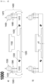
- FIG. 3 is a sectional view of a pouch-shaped battery sealing apparatus 5000 according to a first embodiment of the present invention, showing operation examples a) and b) thereof.
- the pouch-shaped battery sealing apparatus includes an upper sealing block 5100, a lower sealing block 5200, and stopper units 5300 and 5400 configured to maintain the minimum distance between the upper sealing block 5100 and the lower sealing block 5200.
- a left stopper unit and a right stopper unit which have the same construction, are disposed at left and right sides in a symmetrical fashion.
- the stopper units 5300 and 5400 include stoppers 5310 and 5410 configured to contact the upper sealing block 5100 in order to prevent downward movement of the upper sealing block 5100; support shafts 5330 and 5430 disposed at at least one side of the upper sealing block 5100, the support shafts being configured to allow the stoppers 5310 and 5410 to support the upper sealing block 5100 while changing the positions of the stoppers 5310 and 5410 through upward and downward movement; measurement portions 5350 and 5450 configured to measure movement changes of the stoppers 5310 and 5410; and height adjustment portions 5370 and 5470 configured to adjust positions at which the stoppers 5350 and 5450 are fixed.
- the measurement portions 5350 and 5450 are micrometers configured to measure upward and downward movement distances of the stoppers 5310 and 5410.
- the height adjustment portions 5370 and 5470 adjust the heights of the stoppers 5310 and 5410 through rotation of screws thereof.
- the distance for sealing of the pouch-shaped battery is changed in units of micrometers, there is a difference in the degree of sealing and a defect rate.
- the micrometers are used.
- the stoppers 5310 and 5410 are moved upwards and downwards along the support shafts 5330 and 5430 in parallel to each other.
- the support shafts 5350 and 5450 are provided with guides (not shown) configured to allow the stoppers 5350 and 5450 to be moved therealong.
- the height adjustment portions 5370 and 5470 are fixed to through-holes formed in the stoppers 5310 and 5410, the through-holes being provided with screw threads, in a screw-engagement manner. When the screws of the height adjustment portions 5370 and 5470 are rotated, the stoppers 5310 and 5410 move upwards and downwards in response thereto.
- the height adjustment portions 5370 and 5470 and the measurement portions 5350 and 5450 are fixed to fixing portions 5390 and 5490 so as to be located at constant positions from the lower sealing block 5200.
- the lower figure b) of FIG. 3 shows that the upper sealing block 5100 and the lower sealing block 5200 are constantly adjusted so as to have a distance of d5 therebetween by the stoppers 5310 and 5410.
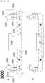
- FIG. 4 is a sectional view showing a first operation example 1000 of a pouch-shaped battery sealing apparatus according to a second embodiment of the present invention
- FIG. 5 is a sectional view showing a second operation example 2000 of the pouch-shaped battery sealing apparatus according to the second embodiment of the present invention
- FIG. 6 is a sectional view showing a third operation example 3000 of the pouch-shaped battery sealing apparatus according to the second embodiment of the present invention
- FIG. 7 is a sectional view showing a fourth operation example 4000 of the pouch-shaped battery sealing apparatus according to the second embodiment of the present invention.
- the pouch-shaped battery sealing apparatus according to the first embodiment of the present invention and the pouch-shaped battery sealing apparatus according to the second embodiment of the present invention are different from each other in terms of stopper movement.
- the entireties of the stoppers 5310 and 5410 move upwards and downwards along the support shafts 5350 and 5450 in parallel to each other.
- stoppers are rotated about rotation shafts 1330, 2330, 3330, 4330, 1430, 2430, 3430, 4430 provided at support shafts (not shown).
- the stoppers perform rotational movement, unlike the first embodiment. Consequently, values measured by measurement portions are not used as they are, distances from the rotation shafts are measured, and distances d1, d2, d3, d4, d4L, and d4R between an upper sealing block and a lower sealing block are calculated through an arithmetic expression thereof, or the distances d1, d2, d3, d4, d4L, and d4R between the upper sealing block and the lower sealing block are calculated through correlation between the values measured by the measurement portions and the measured actual distance between the upper sealing block and the lower sealing block.
- FIG. 4 shows that an upper sealing block 1100 is fixed in the state in which both stoppers 1310 and 1410 are horizontal
- FIG. 5 shows that an upper sealing block 2100 is fixed in the state in which both stoppers 2310 and 2410 are moved downwards as the result of rotational movement
- FIG. 6 shows that an upper sealing block 3100 is fixed in the state in which both stoppers 3310 and 3410 are moved upwards as the result of rotational movement
- FIG. 7 shows that an upper sealing block 3100 is fixed in the state in which one of stoppers 4310 and 4410 is moved upwards and the other stopper is moved downwards as the result of rotational movement. Consequently, the same distances are maintained even in the state in which a lower sealing block is not horizontal. It can be seen that d4, d4L, and d4R are equal to each other.
- the present invention relates to a pouch-shaped battery sealing apparatus including a stopper capable of adjusting a thickness after sealing in a process of sealing the outer edge of a battery case made of a laminate sheet by applying heat and pressure thereto when a pouch-shaped battery is manufactured and a pouch-shaped battery sealing method using the same, and therefore the present invention has industrial applicability.
Landscapes
- Engineering & Computer Science (AREA)
- Mechanical Engineering (AREA)
- Chemical & Material Sciences (AREA)
- Chemical Kinetics & Catalysis (AREA)
- Electrochemistry (AREA)
- General Chemical & Material Sciences (AREA)
- Manufacturing & Machinery (AREA)
- Sealing Battery Cases Or Jackets (AREA)
Abstract
Description
- This application claims the benefit of priority to
Korean Patent Application No. 2020-0146813 filed on November 5, 2020 - The present invention relates to a pouch-shaped battery sealing apparatus including a stopper and a pouch-shaped battery sealing method using the same. More particularly, the present invention relates to a pouch-shaped battery sealing apparatus including a stopper capable of adjusting a thickness after sealing in a process of sealing the outer edge of a battery case made of a laminate sheet by applying heat and pressure thereto when a pouch-shaped battery is manufactured and a pouch-shaped battery sealing method using the same.
- Demand for a secondary battery as an energy source for mobile devices, electric vehicles, etc. has abruptly increased. In particular, demand for a lithium secondary battery, which has high energy density and high discharge voltage, is high.
- Based on the shape and material thereof, the lithium secondary battery may be classified as a cylindrical secondary battery made of a metal material, a prismatic secondary battery made of a metal material, or a pouch-shaped battery made of a laminate sheet. The pouch-shaped battery has advantages in that the pouch-shaped battery is stacked with high integration, thereby having high energy density per unit weight, is manufactured at low cost, and is easily deformable. Consequently, the pouch-shaped battery is used in various devices.
- In the pouch-shaped battery, a laminate sheet including an outer coating layer, a metal blocking layer, and an inner adhesive layer is generally shaped so as to be used as a battery case. An electrode assembly is received in a receiving portion formed in the laminate sheet together with an electrolytic solution, and the receiving portion is hermetically sealed to manufacture the pouch-shaped battery
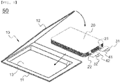
- As shown in
FIG. 1 , a pouch-shaped battery 50 is configured to have a structure in which anelectrode assembly 20 is mounted in a receivingportion 13 of abattery case 10 constituted by alower pouch portion 11 and anupper pouch portion 12. In theelectrode assembly 20, positive andnegative electrode tabs battery case 10. The outer edge of thecase 10 is hermetically sealed in the state in which pairs ofinsulative films - The outer edge of the
case 10 is hermetically sealed as the result of an inner adhesive layer of a laminate sheet being melted by heat and pressed by a rectangular parallelepiped sealing tool that is long in a longitudinal direction. -
FIG. 2 is an exploded perspective view of a pouch-shapedbattery sealing apparatus 500 according to Patent Document 1. The outer edge of a pouch-shaped battery is disposed between aholder 100 and asealing block 200. Theholder 100, which is configured to be moved upwards and downwards by a lifting means 110, heats and fuses the outer edge of the pouch-shaped battery while being moved downwards, whereby the outer edge of the pouch-shaped battery is hermetically sealed. Since there is no separate interval or distance control means between theholder 100 and thesealing block 200, the degree of pressure applied to the pouch-shaped battery varies depending on pressure applied by the lifting means 110. If pressing is excessively performed, there occurs a thermal deformation problem in that an inner adhesive layer of a laminate sheet melts and protrudes outwards. - In Patent Document 1, in order to solve this problem, a
spacing member 300 is inserted such that uniform distance between theholder 100 and thesealing block 200 is maintained, whereby the thermal deformation problem is solved. - As the result of continuous examination of the above sealing problem, the inventors have found that the distance between the
holder 100 and thesealing block 200 is one of the most essential factors in sealing the pouch-shaped battery. The inventors have also found that it is possible to greatly reduce a defect rate while increasing sealing strength through adjustment of the distance therebetween. Even though the distance between theholder 100 and thesealing block 200 is changed merely a few micrometers, great difference occurs in sealing strength and a defect rate based thereon. - The distance, which is such a sensitively reactive variable, is also affected by the following various factors. It is necessary to adjust the distance between the
holder 100 and thesealing block 200 depending on whether an electrode lead is disposed, the kind and thickness of a metal of a metal blocking layer of the laminate sheet, the thickness and adhesive component of the inner adhesive layer of the laminate sheet, kind and thickness of a metal of the electrode lead, the thickness and component of an insulative film, and temperatures of the holder and the sealing block. - As can also been seen from Patent Document 1, such a problem is not recognized, and the
holder 100 and thesealing block 200 are spaced apart from each other by a predetermined distance merely to solve the thermal deformation problem. In the conventional art including Patent Document 1, therefore, only a spacing member of a fixed size is used. - As previously described, the inventors have found that the distance between the
holder 100 and thesealing block 200 is a very important factor in sealing and that, when various sealing distances based on various process conditions are provided to this end, it is possible to greatly reduce a defect rate. - In the initial stage, the inventors tried to manufacture spacing members having various heights and to check the results of sealing based on distance using the same. However, the inventors have found that conducting experiments using spacing members, generally made of a metal material, manufactured so as to be different from each other in units of micrometers is almost physically impossible, and have derived the present invention in a process of solving this problem.
- Patent Document 2 relates to a battery module manufacturing method and an instrument characteristics measurement apparatus. Patent Document 2 includes a process of measuring correspondence between load applied between a first circumferential surface of a battery cell and a second circumference of the battery cell opposite the first circumferential surface and the distance between the first circumferential surface and the second circumferential surface, a process of calculating the distance between the first circumferential surface and the second circumferential surface of first load preset in the measured correspondence, and a process of inserting the battery cell between a chassis that contacts the first circumferential surface and a support plate that contacts the second circumferential surface and mounting the support plate to the chassis in the state in which the distance between the first circumferential surface and the second circumferential surface is set to a required distance between the first circumferential surface and the second circumferential surface.
- In Patent Document 2, (A), (D') the battery cell is compressed between the first circumferential surface and the second circumferential surface in the state in which load is added, and a core is formed between the first circumferential surface and the second circumferential surface to adjust the distance between the first circumferential surface and the second circumferential surface; however, a construction for measuring movement to calculate an exact distance, which is one of the constructions according to the present invention for solving the problem, is absent.
- Patent Document 3 relates to an apparatus and method for measuring the thickness of a secondary battery cell. Patent Document 3 includes a mounting table on which a secondary battery cell, the thickness of which is to be measured, is placed; a pressing plate opposite the mounting table in the state in which the secondary battery cell is disposed therebetween, the pressing plate being installed such that the distance between the pressing plate and the mounting plate is variable; a pressing means configured to push or pull the pressing plate toward or from the mounting table in order to press the secondary battery cell placed on the mounting table in a thickness direction thereof; a measurement means configured to measure pressing force applied to the pressing plate by the pressing means and the thickness of the secondary battery cell at time intervals; and a controller configured to control charging, discharging, or temperature of the secondary battery cell according to measurement conditions input by an operator, to receive the measured pressing force value and the measured thickness value from the measurement means at time intervals, to determine the magnitude of the pressing force applied to the pressing plate and the thickness of the secondary battery cell, to store the determined magnitude of the pressing force and the determined thickness of the secondary battery cell in a memory together with time information, and to maintain or change pressing force applied to the pressing plate by the pressing means during measurement of the thickness of the secondary battery cell.
- Patent Document 3 relates to merely an apparatus for measuring the thickness of the secondary battery cell, and thus cannot be a solution to the problem to be solved by the present invention.
- Patent Document 4 relates to a clamping device for stacking electrochemical cells, and Patent Document 5 relates to a battery cell pressing apparatus and a battery cell pressing method using the same. These patent documents do not describe whether to measure the distance.
- As described above, a measurement apparatus capable of accurately adjusting the distance between a holder and a sealing block and determining the degree of sealing based thereon in sealing a pouch-shaped battery, recognized as an important problem in the present invention, and a measurement method using the same have not yet been suggested.
-
Korean Patent Application Publication No. 2015-0025684 -
Japanese Patent Application Publication No. 2019-185929 (2019.10.24 -
Korean Patent Application Publication No. 2016-0063278 (2016.06.03 -
Korean Patent Application Publication No. 2015-0141966 (2015.12.21 -
Korean Patent Application Publication No. 2015-0089555 (2015.08.05 - The present invention has been made in view of the above problems, and it is an object of the present invention to provide a pouch-shaped battery sealing apparatus capable of accurately adjusting the distance between a holder and a sealing block and the degree of sealing based thereon in a process of sealing the outer edge of a battery case made of a laminate sheet by applying heat and pressure thereto when a pouch-shaped battery is manufactured and a pouch-shaped battery sealing method using the same.
- In order to accomplish the above object, the present invention provides a pouch-shaped battery sealing apparatus including an upper sealing block, a lower sealing block, and a stopper unit configured to maintain the minimum distance between the upper sealing block and the lower sealing block, wherein the stopper unit includes a stopper configured to contact the upper sealing block in order to prevent downward movement of the upper sealing block; a support shaft disposed at at least one side of the upper sealing block, the support shaft being configured to allow the stopper to support the upper sealing block while changing the position of the stopper through upward and downward movement or rotational movement; a measurement portion configured to measure a movement change of the stopper; and a height adjustment portion configured to adjust the position at which the stopper is fixed.
- The stopper unit may be disposed at left and right surfaces of the upper sealing block in a symmetrical fashion while having an identical construction.
- The measurement portion may be a micrometer configured to measure the upward and downward movement distance of the stopper, and the height adjustment portion may be configured to adjust the height of the stopper by rotation of a screw thereof.
- In another aspect, the pouch-shaped battery sealing apparatus may further include a fixing portion configured to fix the height adjustment portion and the measurement portion at constant positions from the lower sealing block.
- The support shaft may be disposed between the upper sealing block and the measurement portion and the height adjustment portion, the support shaft may be disposed perpendicular to a plane at which the lower sealing block is fixed, and the support shaft may include a guide configured to allow the stopper to be horizontally moved along the support shaft or a rotation shaft configured to allow the stopper to be rotated about the support shaft.
- The stopper may be disposed at each of left and right sides of the upper sealing block, and the left and right distance between the upper sealing block and the lower sealing block may be differently fixed by the stopper.
- The stopper may be disposed at each of left and right sides of the upper sealing block, and a plane at which the upper sealing block is fixed may be inclined by the stopper.
- In a further aspect, the present invention provides a method of adjusting the sealing thickness of a pouch-shaped battery using the pouch-shaped battery sealing apparatus.
- In addition, the present invention may provide all possible combinations of the above solving means.
- As is apparent from the above description, the present invention provides a pouch-shaped battery sealing apparatus capable of accurately adjusting the distance between a holder and a sealing block and the degree of sealing based thereon in a process of sealing the outer edge of a battery case made of a laminate sheet by applying heat and pressure thereto when a pouch-shaped battery is manufactured and a pouch-shaped battery sealing method using the same.
- In the present invention, height adjustment is accurately performed by a height adjustment portion and a change in height is observed by a measurement portion. Consequently, it is possible to accurately and constantly adjust a sealing distance, whereby it is possible to provide consistent results.
- Left and right stoppers according to the present invention are individually adjusted. When a lower sealing block is not horizontal, therefore, it is possible to adjust an upper sealing block based on the state of the lower sealing block.
- Each stopper according to the present invention has a constant position, since a rotation shaft thereof is fixed, and the upper sealing block is supported by the height adjustment portion and the measurement portion according to the lever principle, whereby fixing force is very high while height adjustment is easily performed.
-
-
FIG. 1 is an exploded perspective view of a conventional pouch-shaped battery. -
FIG. 2 is an exploded perspective view of a pouch-shaped battery sealing apparatus according to Patent Document 1. -
FIG. 3 is a sectional view of a pouch-shaped battery sealing apparatus according to a first embodiment of the present invention. -
FIG. 4 is a sectional view showing a first operation example of a pouch-shaped battery sealing apparatus according to a second embodiment of the present invention. -
FIG. 5 is a sectional view showing a second operation example of the pouch-shaped battery sealing apparatus according to the second embodiment of the present invention. -
FIG. 6 is a sectional view showing a third operation example of the pouch-shaped battery sealing apparatus according to the second embodiment of the present invention. -
FIG. 7 is a sectional view showing a fourth operation example of the pouch-shaped battery sealing apparatus according to the second embodiment of the present invention. - Now, preferred embodiments of the present invention will be described in detail with reference to the accompanying drawings such that the preferred embodiments of the present invention can be easily implemented by a person having ordinary skill in the art to which the present invention pertains. In describing the principle of operation of the preferred embodiments of the present invention in detail, however, a detailed description of known functions and configurations incorporated herein will be omitted when the same may obscure the subject matter of the present invention.
- In addition, the same reference numbers will be used throughout the drawings to refer to parts that perform similar functions or operations. In the case in which one part is said to be connected to another part throughout the specification, not only may the one part be directly connected to the other part, but also, the one part may be indirectly connected to the other part via a further part. In addition, that a certain element is included does not mean that other elements are excluded, but means that such elements may be further included unless mentioned otherwise.
- In addition, a description to embody elements through limitation or addition may be applied to all inventions, unless particularly restricted, and does not limit a specific invention.
- Also, in the description of the invention and the claims of the present application, singular forms are intended to include plural forms unless mentioned otherwise.
- Also, in the description of the invention and the claims of the present application, "or" includes "and" unless mentioned otherwise. Therefore, "including A or B" means three cases, namely, the case including A, the case including B, and the case including A and B.
- Hereinafter, embodiments of the present invention will be described with reference to the accompanying drawings.
-
FIG. 3 is a sectional view of a pouch-shapedbattery sealing apparatus 5000 according to a first embodiment of the present invention, showing operation examples a) and b) thereof. - The pouch-shaped battery sealing apparatus according to the present invention includes an
upper sealing block 5100, alower sealing block 5200, andstopper units upper sealing block 5100 and thelower sealing block 5200. InFIGS. 3 to 7 , a left stopper unit and a right stopper unit, which have the same construction, are disposed at left and right sides in a symmetrical fashion. - The
stopper units stoppers upper sealing block 5100 in order to prevent downward movement of theupper sealing block 5100;support shafts upper sealing block 5100, the support shafts being configured to allow thestoppers upper sealing block 5100 while changing the positions of thestoppers measurement portions stoppers height adjustment portions stoppers - The
measurement portions stoppers height adjustment portions stoppers - When the distance for sealing of the pouch-shaped battery is changed in units of micrometers, there is a difference in the degree of sealing and a defect rate. In order to measure variation of the height, the micrometers are used.
- In a first embodiment of the present invention, the
stoppers support shafts support shafts stoppers - The
height adjustment portions stoppers height adjustment portions stoppers - To this end, the
height adjustment portions measurement portions portions lower sealing block 5200. As a result, it is possible to adjust the heights of thestoppers - The lower figure b) of
FIG. 3 shows that theupper sealing block 5100 and thelower sealing block 5200 are constantly adjusted so as to have a distance of d5 therebetween by thestoppers -
FIG. 4 is a sectional view showing a first operation example 1000 of a pouch-shaped battery sealing apparatus according to a second embodiment of the present invention,FIG. 5 is a sectional view showing a second operation example 2000 of the pouch-shaped battery sealing apparatus according to the second embodiment of the present invention,FIG. 6 is a sectional view showing a third operation example 3000 of the pouch-shaped battery sealing apparatus according to the second embodiment of the present invention, andFIG. 7 is a sectional view showing a fourth operation example 4000 of the pouch-shaped battery sealing apparatus according to the second embodiment of the present invention. - The pouch-shaped battery sealing apparatus according to the first embodiment of the present invention and the pouch-shaped battery sealing apparatus according to the second embodiment of the present invention are different from each other in terms of stopper movement. In the first embodiment, the entireties of the
stoppers support shafts - In the second embodiment, stoppers are rotated about
rotation shafts - In the second embodiment, the stoppers perform rotational movement, unlike the first embodiment. Consequently, values measured by measurement portions are not used as they are, distances from the rotation shafts are measured, and distances d1, d2, d3, d4, d4L, and d4R between an upper sealing block and a lower sealing block are calculated through an arithmetic expression thereof, or the distances d1, d2, d3, d4, d4L, and d4R between the upper sealing block and the lower sealing block are calculated through correlation between the values measured by the measurement portions and the measured actual distance between the upper sealing block and the lower sealing block.
-
FIG. 4 shows that anupper sealing block 1100 is fixed in the state in which bothstoppers FIG. 5 shows that anupper sealing block 2100 is fixed in the state in which bothstoppers FIG. 6 shows that anupper sealing block 3100 is fixed in the state in which bothstoppers FIG. 7 shows that anupper sealing block 3100 is fixed in the state in which one ofstoppers - Those skilled in the art to which the present invention pertains will appreciate that various applications and modifications are possible within the category of the present invention based on the above description.
-
- 10: Battery case
- 11: Lower portion
- 12: Upper portion
- 13: Receiving portion
- 20: Electrode assembly
- 21, 22: Electrode tabs
- 31, 32: Electrode leads
- 41, 42: Insulative films
- 50: Pouch-shaped battery
- 100: Holder
- 110: Lifting means
- 200: Sealing block
- 300: Spacing member
- 500: Conventional pouch-shaped battery sealing apparatus
- 1000: First operation example of pouch-shaped battery sealing apparatus according to second embodiment of present invention
- 2000: Second operation example of pouch-shaped battery sealing apparatus according to second embodiment of present invention
- 3000: Third operation example of pouch-shaped battery sealing apparatus according to second embodiment of present invention
- 4000: Fourth operation example of pouch-shaped battery sealing apparatus according to second embodiment of present invention
- 5000: Operation example of pouch-shaped battery sealing apparatus according to first embodiment of present invention
- 1100, 2100, 3100, 4100, 5100: Upper sealing blocks
- 1200, 2200, 3200, 4200, 5200: Lower sealing blocks
- 1300, 2300, 3300, 4300, 5300: Left stopper units
- 1400, 2400, 3400, 4400, 5400: Right stopper units
- 1310, 2310, 3310, 4310, 5310: Left stoppers
- 1410, 2410, 3410, 4410, 5410: Right stoppers
- 1330, 2330, 3330, 4330: Left rotation shafts
- 1430, 2430, 3430, 4430: Right rotation shafts
- 5330: Left support shaft
- 5430: Right support shaft
- 1350, 2350, 3350, 4350, 5350, 1450, 2450, 3450, 4450, 5450: Measurement portions
- 1370, 2370, 3370, 4370, 5370, 1470, 2470, 3470, 4470, 5470: Height adjustment portions
- 1390, 2390, 3390, 4390, 5390, 1490, 2490, 3490, 4490, 5490: Fixing portions
- d1, d2, d3, d4, d4L, d4R, d5: Distances between upper sealing blocks and lower sealing blocks
- The present invention relates to a pouch-shaped battery sealing apparatus including a stopper capable of adjusting a thickness after sealing in a process of sealing the outer edge of a battery case made of a laminate sheet by applying heat and pressure thereto when a pouch-shaped battery is manufactured and a pouch-shaped battery sealing method using the same, and therefore the present invention has industrial applicability.
Claims (11)
- A pouch-shaped battery sealing apparatus comprising an upper sealing block, a lower sealing block, and a stopper unit configured to maintain a minimum distance between the upper sealing block and the lower sealing block, wherein the stopper unit comprises:a stopper configured to contact the upper sealing block in order to prevent downward movement of the upper sealing block;a support shaft disposed at at least one side of the upper sealing block, the support shaft being configured to allow the stopper to support the upper sealing block while changing a position of the stopper through upward and downward movement or rotational movement;a measurement portion configured to measure a movement change of the stopper; anda height adjustment portion configured to adjust a position at which the stopper is fixed.
- The pouch-shaped battery sealing apparatus according to claim 1, wherein the stopper unit is disposed at left and right surfaces of the upper sealing block in a symmetrical fashion while having an identical construction.
- The pouch-shaped battery sealing apparatus according to claim 1, wherein the measurement portion is a micrometer configured to measure an upward and downward movement distance of the stopper.
- The pouch-shaped battery sealing apparatus according to claim 1, wherein the height adjustment portion is configured to adjust a height of the stopper by rotation of a screw thereof.
- The pouch-shaped battery sealing apparatus according to claim 1, further comprising a fixing portion configured to fix the height adjustment portion and the measurement portion at constant positions from the lower sealing block.
- The pouch-shaped battery sealing apparatus according to claim 1, wherein the support shaft is disposed between the upper sealing block and the measurement portion and the height adjustment portion.
- The pouch-shaped battery sealing apparatus according to claim 1, wherein the support shaft is disposed perpendicular to a plane at which the lower sealing block is fixed.
- The pouch-shaped battery sealing apparatus according to claim 7, wherein the support shaft comprises a guide configured to allow the stopper to be horizontally moved along the support shaft or a rotation shaft configured to allow the stopper to be rotated about the support shaft.
- The pouch-shaped battery sealing apparatus according to claim 1, whereinthe stopper is disposed at each of left and right sides of the upper sealing block, anda left and right distance between the upper sealing block and the lower sealing block is differently fixed by the stopper.
- The pouch-shaped battery sealing apparatus according to claim 1, whereinthe stopper is disposed at each of left and right sides of the upper sealing block, anda plane at which the upper sealing block is fixed is inclined by the stopper.
- A method of adjusting a sealing thickness of a pouch-shaped battery using the pouch-shaped battery sealing apparatus according to any one of claims 1 to 10.
Applications Claiming Priority (2)
| Application Number | Priority Date | Filing Date | Title |
|---|---|---|---|
| KR1020200146813A KR20220060807A (en) | 2020-11-05 | 2020-11-05 | Pouch-type secondary battery sealing device comprising a stopper and sealing method of pouch-type secondary battery using the same |
| PCT/KR2021/015774 WO2022098077A1 (en) | 2020-11-05 | 2021-11-03 | Pouch battery sealing device comprising stopper and pouch battery sealing method using same |
Publications (3)
| Publication Number | Publication Date |
|---|---|
| EP4129632A1 true EP4129632A1 (en) | 2023-02-08 |
| EP4129632A4 EP4129632A4 (en) | 2023-11-08 |
| EP4129632B1 EP4129632B1 (en) | 2025-09-10 |
Family
ID=81458070
Family Applications (1)
| Application Number | Title | Priority Date | Filing Date |
|---|---|---|---|
| EP21889542.3A Active EP4129632B1 (en) | 2020-11-05 | 2021-11-03 | Pouch battery sealing device comprising stopper and pouch battery sealing method using same |
Country Status (7)
| Country | Link |
|---|---|
| US (1) | US20230207856A1 (en) |
| EP (1) | EP4129632B1 (en) |
| JP (1) | JP7428314B2 (en) |
| KR (1) | KR20220060807A (en) |
| CN (1) | CN115666906A (en) |
| ES (1) | ES3055892T3 (en) |
| WO (1) | WO2022098077A1 (en) |
Families Citing this family (3)
| Publication number | Priority date | Publication date | Assignee | Title |
|---|---|---|---|---|
| KR20240020040A (en) * | 2022-08-05 | 2024-02-14 | 주식회사 엘지에너지솔루션 | Seaing device |
| KR20250008367A (en) * | 2023-07-07 | 2025-01-14 | 주식회사 엘지에너지솔루션 | Sealing tool inspection device and battery cell sealing system including same |
| KR20250098381A (en) * | 2023-12-22 | 2025-07-01 | 주식회사 엘지에너지솔루션 | Battery Cell Sealing Device Comprising Gap Measuring Part |
Family Cites Families (23)
| Publication number | Priority date | Publication date | Assignee | Title |
|---|---|---|---|---|
| JP2002298799A (en) | 2001-04-02 | 2002-10-11 | Sony Corp | Hermetic sealing device |
| JP2013166287A (en) | 2012-02-15 | 2013-08-29 | Tokyo Electron Ltd | Heat sealing device and heat sealing method |
| WO2014158768A1 (en) | 2013-03-14 | 2014-10-02 | Enevate Corporation | Clamping device for an electrochemical cell stack |
| KR102084100B1 (en) * | 2013-08-22 | 2020-04-14 | 삼성에스디아이 주식회사 | Pouch type rechargeable battery |
| KR20150025684A (en) | 2013-08-30 | 2015-03-11 | 주식회사 엘지화학 | Impeller mixer of electrode slurry |
| KR101763980B1 (en) * | 2013-08-30 | 2017-08-01 | 주식회사 엘지화학 | Sealiing tool of pouch type secondary battery |
| KR101910686B1 (en) | 2014-01-28 | 2018-10-22 | 주식회사 엘지화학 | Apparatus of pressuring battery cell and method of pressuring battery cell using the same |
| CN104154888B (en) * | 2014-07-25 | 2016-12-07 | 四川工程职业技术学院 | A kind of miniature parts Precision measurement platform |
| KR101783923B1 (en) | 2014-11-26 | 2017-10-10 | 주식회사 엘지화학 | Apparatus and Method of Measuring Thickness of Secondary Battery Cell |
| CN204444719U (en) * | 2015-03-02 | 2015-07-08 | 三峡大学 | Detachable screw mandrel regulation type just combines just Mobile table and accessory thereof |
| KR20170046910A (en) * | 2015-10-22 | 2017-05-04 | 제일특수소재주식회사 | Electrode tab bonding apparatus for secondary battery |
| KR101762807B1 (en) * | 2016-01-28 | 2017-07-28 | 주식회사 탑앤씨 | Pouch Film Sealing Apparatus for Secondary Battery |
| KR102174607B1 (en) * | 2016-09-09 | 2020-11-05 | 주식회사 엘지화학 | Sealing Device for Battery Case Comprising Sealing Protrusion and Method of Manufacturing Battery Cell Using the Same |
| KR102647221B1 (en) * | 2016-12-22 | 2024-03-14 | 에스케이온 주식회사 | Sealing Device for Secondary Battery |
| KR102109926B1 (en) * | 2017-07-20 | 2020-05-12 | 주식회사 엘지화학 | Pouch case for secondary battery, pouch type secondary battery and manufacturing method thereof using the same |
| EP3718749B1 (en) | 2017-11-30 | 2023-08-30 | Nagano Automation Co., Ltd. | Melt-bonding device |
| KR102320013B1 (en) * | 2018-03-12 | 2021-11-02 | 주식회사 엘지에너지솔루션 | Sealing device for rechargeable battery |
| KR20190107922A (en) * | 2018-03-13 | 2019-09-23 | 주식회사 엠플러스 | Sealing unit corresponding to thermal deformation |
| JP2019175799A (en) | 2018-03-29 | 2019-10-10 | 株式会社エンビジョンAescジャパン | Heat seal device |
| JP7133964B2 (en) | 2018-04-04 | 2022-09-09 | 三菱電機株式会社 | BATTERY MODULE MANUFACTURING METHOD AND MECHANICAL PROPERTIES MEASURING DEVICE |
| CN109398770A (en) * | 2018-09-26 | 2019-03-01 | 河南慧锦药业有限公司 | A kind of pharmaceutical purpose particle packaging machine |
| KR102930411B1 (en) * | 2020-02-20 | 2026-02-25 | 주식회사 엘지에너지솔루션 | Rolling apparatus for secondary battery |
| CN211507815U (en) * | 2020-04-13 | 2020-09-15 | 深圳市量能科技有限公司 | Polymer lithium ion battery capper and preparation system |
-
2020
- 2020-11-05 KR KR1020200146813A patent/KR20220060807A/en active Pending
-
2021
- 2021-11-03 EP EP21889542.3A patent/EP4129632B1/en active Active
- 2021-11-03 ES ES21889542T patent/ES3055892T3/en active Active
- 2021-11-03 CN CN202180035816.6A patent/CN115666906A/en active Pending
- 2021-11-03 US US17/926,813 patent/US20230207856A1/en active Pending
- 2021-11-03 JP JP2022567771A patent/JP7428314B2/en active Active
- 2021-11-03 WO PCT/KR2021/015774 patent/WO2022098077A1/en not_active Ceased
Also Published As
| Publication number | Publication date |
|---|---|
| JP2023527689A (en) | 2023-06-30 |
| CN115666906A (en) | 2023-01-31 |
| ES3055892T3 (en) | 2026-02-16 |
| EP4129632A4 (en) | 2023-11-08 |
| KR20220060807A (en) | 2022-05-12 |
| EP4129632B1 (en) | 2025-09-10 |
| JP7428314B2 (en) | 2024-02-06 |
| WO2022098077A1 (en) | 2022-05-12 |
| US20230207856A1 (en) | 2023-06-29 |
Similar Documents
| Publication | Publication Date | Title |
|---|---|---|
| EP4129632B1 (en) | Pouch battery sealing device comprising stopper and pouch battery sealing method using same | |
| EP2993725A1 (en) | Charging and discharging inspection device and charging and discharging inspection method for thin secondary battery | |
| EP3800702A1 (en) | Bus bar for battery cell connection, battery pack, and manufacturing method therefor | |
| JP2010032492A (en) | Pressure measuring device and thickness measuring device | |
| EP4026651B1 (en) | Welding quality inspection device | |
| KR102795945B1 (en) | Defective Inspection Device of Pouch-type Battery Cell | |
| EP4318730B1 (en) | Shock test apparatus for pouch-shaped battery cells and shock test method for pouch-shaped battery cells using the same | |
| EP4087011B1 (en) | Battery cell jig comprising spacer laminate, apparatus comprising same for measuring volume of battery cell, and method for measuring volume of battery cell using same | |
| KR20230029203A (en) | Tab fold detection device for secondary battery and method for detecting tab fold using the same | |
| EP4135107A1 (en) | Pouch-type battery sealing device comprising position adjustment unit, and pouch-type battery sealing method using same | |
| KR20230007070A (en) | Jog for measuring impedance of a battery cell including a pressing jig and device for measuring impedance of a battery cell including the same | |
| EP4087010B1 (en) | Apparatus for measuring volume of a battery cell comprising a battery cell jig including a spacer and method for measuring volume of battery cell using same | |
| US20250219126A1 (en) | Method for manufacturing a power storage device | |
| EP4156360B1 (en) | Mono-cell manufacturing device having glossmeter and manufacturing method using same | |
| KR102218034B1 (en) | Height gauge for measuring side folding portion of cell | |
| EP4668386A1 (en) | Compressing device, capable of real-time monitoring of compressing force, for formation of secondary battery, and compressing method thereof | |
| KR102064307B1 (en) | Device of Measuring Thickness by Regulating Impulse to Battery Cell | |
| KR102955823B1 (en) | Pouch-type secondary battery sealing device comprising a position adjustment part and sealing method of pouch-type secondary battery using the same | |
| US20250219212A1 (en) | Method for manufacturing a power storage device | |
| EP4424495A1 (en) | Sealing apparatus | |
| KR102931771B1 (en) | Inspection method for battery cell | |
| JP2019185929A (en) | Manufacturing method of battery module and mechanical characteristic measuring apparatus | |
| KR20260035439A (en) | Apparatus and method for loading electrodes | |
| KR20230060999A (en) | Pouch cell sealing part thickness measuring device and measuring method using the same |
Legal Events
| Date | Code | Title | Description |
|---|---|---|---|
| STAA | Information on the status of an ep patent application or granted ep patent |
Free format text: STATUS: THE INTERNATIONAL PUBLICATION HAS BEEN MADE |
|
| PUAI | Public reference made under article 153(3) epc to a published international application that has entered the european phase |
Free format text: ORIGINAL CODE: 0009012 |
|
| STAA | Information on the status of an ep patent application or granted ep patent |
Free format text: STATUS: REQUEST FOR EXAMINATION WAS MADE |
|
| 17P | Request for examination filed |
Effective date: 20221104 |
|
| AK | Designated contracting states |
Kind code of ref document: A1 Designated state(s): AL AT BE BG CH CY CZ DE DK EE ES FI FR GB GR HR HU IE IS IT LI LT LU LV MC MK MT NL NO PL PT RO RS SE SI SK SM TR |
|
| REG | Reference to a national code |
Ref country code: DE Ref legal event code: R079 Free format text: PREVIOUS MAIN CLASS: B29C0065000000 Ipc: B29C0065020000 Ref document number: 602021038523 Country of ref document: DE |
|
| A4 | Supplementary search report drawn up and despatched |
Effective date: 20231009 |
|
| RIC1 | Information provided on ipc code assigned before grant |
Ipc: H01M 50/124 20210101ALN20231002BHEP Ipc: H01M 50/105 20210101ALN20231002BHEP Ipc: H01M 10/04 20060101ALI20231002BHEP Ipc: B29C 65/02 20060101AFI20231002BHEP |
|
| DAV | Request for validation of the european patent (deleted) | ||
| DAX | Request for extension of the european patent (deleted) | ||
| GRAP | Despatch of communication of intention to grant a patent |
Free format text: ORIGINAL CODE: EPIDOSNIGR1 |
|
| STAA | Information on the status of an ep patent application or granted ep patent |
Free format text: STATUS: GRANT OF PATENT IS INTENDED |
|
| RIC1 | Information provided on ipc code assigned before grant |
Ipc: H01M 50/124 20210101ALN20250507BHEP Ipc: H01M 50/105 20210101ALN20250507BHEP Ipc: H01M 10/04 20060101ALI20250507BHEP Ipc: B29C 65/02 20060101AFI20250507BHEP |
|
| RIC1 | Information provided on ipc code assigned before grant |
Ipc: H01M 50/124 20210101ALN20250514BHEP Ipc: H01M 50/105 20210101ALN20250514BHEP Ipc: H01M 10/04 20060101ALI20250514BHEP Ipc: B29C 65/02 20060101AFI20250514BHEP |
|
| INTG | Intention to grant announced |
Effective date: 20250602 |
|
| GRAS | Grant fee paid |
Free format text: ORIGINAL CODE: EPIDOSNIGR3 |
|
| GRAA | (expected) grant |
Free format text: ORIGINAL CODE: 0009210 |
|
| STAA | Information on the status of an ep patent application or granted ep patent |
Free format text: STATUS: THE PATENT HAS BEEN GRANTED |
|
| AK | Designated contracting states |
Kind code of ref document: B1 Designated state(s): AL AT BE BG CH CY CZ DE DK EE ES FI FR GB GR HR HU IE IS IT LI LT LU LV MC MK MT NL NO PL PT RO RS SE SI SK SM TR |
|
| REG | Reference to a national code |
Ref country code: GB Ref legal event code: FG4D |
|
| REG | Reference to a national code |
Ref country code: CH Ref legal event code: EP |
|
| REG | Reference to a national code |
Ref country code: DE Ref legal event code: R096 Ref document number: 602021038523 Country of ref document: DE |
|
| REG | Reference to a national code |
Ref country code: IE Ref legal event code: FG4D |
|
| P01 | Opt-out of the competence of the unified patent court (upc) registered |
Free format text: CASE NUMBER: UPC_APP_8079_4129632/2025 Effective date: 20250926 |
|
| PGFP | Annual fee paid to national office [announced via postgrant information from national office to epo] |
Ref country code: DE Payment date: 20251020 Year of fee payment: 5 |
|
| PGFP | Annual fee paid to national office [announced via postgrant information from national office to epo] |
Ref country code: GB Payment date: 20251023 Year of fee payment: 5 |
|
| PG25 | Lapsed in a contracting state [announced via postgrant information from national office to epo] |
Ref country code: NO Free format text: LAPSE BECAUSE OF FAILURE TO SUBMIT A TRANSLATION OF THE DESCRIPTION OR TO PAY THE FEE WITHIN THE PRESCRIBED TIME-LIMIT Effective date: 20251210 |
|
| REG | Reference to a national code |
Ref country code: LT Ref legal event code: MG9D |
|
| PGFP | Annual fee paid to national office [announced via postgrant information from national office to epo] |
Ref country code: AT Payment date: 20260113 Year of fee payment: 5 |
|
| PG25 | Lapsed in a contracting state [announced via postgrant information from national office to epo] |
Ref country code: FI Free format text: LAPSE BECAUSE OF FAILURE TO SUBMIT A TRANSLATION OF THE DESCRIPTION OR TO PAY THE FEE WITHIN THE PRESCRIBED TIME-LIMIT Effective date: 20250910 |
|
| REG | Reference to a national code |
Ref country code: NL Ref legal event code: MP Effective date: 20250910 |
|
| PG25 | Lapsed in a contracting state [announced via postgrant information from national office to epo] |
Ref country code: HR Free format text: LAPSE BECAUSE OF FAILURE TO SUBMIT A TRANSLATION OF THE DESCRIPTION OR TO PAY THE FEE WITHIN THE PRESCRIBED TIME-LIMIT Effective date: 20250910 |
|
| PGFP | Annual fee paid to national office [announced via postgrant information from national office to epo] |
Ref country code: FR Payment date: 20251021 Year of fee payment: 5 |
|
| PG25 | Lapsed in a contracting state [announced via postgrant information from national office to epo] |
Ref country code: GR Free format text: LAPSE BECAUSE OF FAILURE TO SUBMIT A TRANSLATION OF THE DESCRIPTION OR TO PAY THE FEE WITHIN THE PRESCRIBED TIME-LIMIT Effective date: 20251211 |
|
| PGFP | Annual fee paid to national office [announced via postgrant information from national office to epo] |
Ref country code: BE Payment date: 20251020 Year of fee payment: 5 |
|
| PG25 | Lapsed in a contracting state [announced via postgrant information from national office to epo] |
Ref country code: SE Free format text: LAPSE BECAUSE OF FAILURE TO SUBMIT A TRANSLATION OF THE DESCRIPTION OR TO PAY THE FEE WITHIN THE PRESCRIBED TIME-LIMIT Effective date: 20250910 |
|
| PG25 | Lapsed in a contracting state [announced via postgrant information from national office to epo] |
Ref country code: LV Free format text: LAPSE BECAUSE OF FAILURE TO SUBMIT A TRANSLATION OF THE DESCRIPTION OR TO PAY THE FEE WITHIN THE PRESCRIBED TIME-LIMIT Effective date: 20250910 |
|
| PG25 | Lapsed in a contracting state [announced via postgrant information from national office to epo] |
Ref country code: PL Free format text: LAPSE BECAUSE OF FAILURE TO SUBMIT A TRANSLATION OF THE DESCRIPTION OR TO PAY THE FEE WITHIN THE PRESCRIBED TIME-LIMIT Effective date: 20250910 Ref country code: BG Free format text: LAPSE BECAUSE OF FAILURE TO SUBMIT A TRANSLATION OF THE DESCRIPTION OR TO PAY THE FEE WITHIN THE PRESCRIBED TIME-LIMIT Effective date: 20250910 |
|
| PG25 | Lapsed in a contracting state [announced via postgrant information from national office to epo] |
Ref country code: RS Free format text: LAPSE BECAUSE OF FAILURE TO SUBMIT A TRANSLATION OF THE DESCRIPTION OR TO PAY THE FEE WITHIN THE PRESCRIBED TIME-LIMIT Effective date: 20251210 |
|
| PGFP | Annual fee paid to national office [announced via postgrant information from national office to epo] |
Ref country code: ES Payment date: 20251215 Year of fee payment: 5 |
|
| REG | Reference to a national code |
Ref country code: AT Ref legal event code: MK05 Ref document number: 1835461 Country of ref document: AT Kind code of ref document: T Effective date: 20250910 |
|
| PG25 | Lapsed in a contracting state [announced via postgrant information from national office to epo] |
Ref country code: NL Free format text: LAPSE BECAUSE OF FAILURE TO SUBMIT A TRANSLATION OF THE DESCRIPTION OR TO PAY THE FEE WITHIN THE PRESCRIBED TIME-LIMIT Effective date: 20250910 |
|
| REG | Reference to a national code |
Ref country code: ES Ref legal event code: FG2A Ref document number: 3055892 Country of ref document: ES Kind code of ref document: T3 Effective date: 20260216 |
|
| PGFP | Annual fee paid to national office [announced via postgrant information from national office to epo] |
Ref country code: HU Payment date: 20251216 Year of fee payment: 5 |
|
| PG25 | Lapsed in a contracting state [announced via postgrant information from national office to epo] |
Ref country code: SM Free format text: LAPSE BECAUSE OF FAILURE TO SUBMIT A TRANSLATION OF THE DESCRIPTION OR TO PAY THE FEE WITHIN THE PRESCRIBED TIME-LIMIT Effective date: 20250910 |
|
| PG25 | Lapsed in a contracting state [announced via postgrant information from national office to epo] |
Ref country code: AT Free format text: LAPSE BECAUSE OF FAILURE TO SUBMIT A TRANSLATION OF THE DESCRIPTION OR TO PAY THE FEE WITHIN THE PRESCRIBED TIME-LIMIT Effective date: 20250910 |
|
| PG25 | Lapsed in a contracting state [announced via postgrant information from national office to epo] |
Ref country code: RO Free format text: LAPSE BECAUSE OF FAILURE TO SUBMIT A TRANSLATION OF THE DESCRIPTION OR TO PAY THE FEE WITHIN THE PRESCRIBED TIME-LIMIT Effective date: 20250910 Ref country code: IT Free format text: LAPSE BECAUSE OF FAILURE TO SUBMIT A TRANSLATION OF THE DESCRIPTION OR TO PAY THE FEE WITHIN THE PRESCRIBED TIME-LIMIT Effective date: 20250910 |
|
| PG25 | Lapsed in a contracting state [announced via postgrant information from national office to epo] |
Ref country code: IS Free format text: LAPSE BECAUSE OF FAILURE TO SUBMIT A TRANSLATION OF THE DESCRIPTION OR TO PAY THE FEE WITHIN THE PRESCRIBED TIME-LIMIT Effective date: 20260110 |
|
| PG25 | Lapsed in a contracting state [announced via postgrant information from national office to epo] |
Ref country code: CZ Free format text: LAPSE BECAUSE OF FAILURE TO SUBMIT A TRANSLATION OF THE DESCRIPTION OR TO PAY THE FEE WITHIN THE PRESCRIBED TIME-LIMIT Effective date: 20250910 Ref country code: PT Free format text: LAPSE BECAUSE OF FAILURE TO SUBMIT A TRANSLATION OF THE DESCRIPTION OR TO PAY THE FEE WITHIN THE PRESCRIBED TIME-LIMIT Effective date: 20260112 |
|
| PG25 | Lapsed in a contracting state [announced via postgrant information from national office to epo] |
Ref country code: EE Free format text: LAPSE BECAUSE OF FAILURE TO SUBMIT A TRANSLATION OF THE DESCRIPTION OR TO PAY THE FEE WITHIN THE PRESCRIBED TIME-LIMIT Effective date: 20250910 Ref country code: SK Free format text: LAPSE BECAUSE OF FAILURE TO SUBMIT A TRANSLATION OF THE DESCRIPTION OR TO PAY THE FEE WITHIN THE PRESCRIBED TIME-LIMIT Effective date: 20250910 |