EP4129623A1 - Pouch bending guide apparatus and pouch bending method for secondary battery packaging system using stopping means - Google Patents
Pouch bending guide apparatus and pouch bending method for secondary battery packaging system using stopping means Download PDFInfo
- Publication number
- EP4129623A1 EP4129623A1 EP20928648.3A EP20928648A EP4129623A1 EP 4129623 A1 EP4129623 A1 EP 4129623A1 EP 20928648 A EP20928648 A EP 20928648A EP 4129623 A1 EP4129623 A1 EP 4129623A1
- Authority
- EP
- European Patent Office
- Prior art keywords
- pouch
- bending
- jig
- stopping means
- base
- Prior art date
- Legal status (The legal status is an assumption and is not a legal conclusion. Google has not performed a legal analysis and makes no representation as to the accuracy of the status listed.)
- Granted
Links
Images






Classifications
-
- B—PERFORMING OPERATIONS; TRANSPORTING
- B21—MECHANICAL METAL-WORKING WITHOUT ESSENTIALLY REMOVING MATERIAL; PUNCHING METAL
- B21D—WORKING OR PROCESSING OF SHEET METAL OR METAL TUBES, RODS OR PROFILES WITHOUT ESSENTIALLY REMOVING MATERIAL; PUNCHING METAL
- B21D5/00—Bending sheet metal along straight lines, e.g. to form simple curves
- B21D5/01—Bending sheet metal along straight lines, e.g. to form simple curves between rams and anvils or abutments
-
- B—PERFORMING OPERATIONS; TRANSPORTING
- B29—WORKING OF PLASTICS; WORKING OF SUBSTANCES IN A PLASTIC STATE IN GENERAL
- B29C—SHAPING OR JOINING OF PLASTICS; SHAPING OF MATERIAL IN A PLASTIC STATE, NOT OTHERWISE PROVIDED FOR; AFTER-TREATMENT OF THE SHAPED PRODUCTS, e.g. REPAIRING
- B29C53/00—Shaping by bending, folding, twisting, straightening or flattening; Apparatus therefor
- B29C53/02—Bending or folding
- B29C53/04—Bending or folding of plates or sheets
-
- B—PERFORMING OPERATIONS; TRANSPORTING
- B29—WORKING OF PLASTICS; WORKING OF SUBSTANCES IN A PLASTIC STATE IN GENERAL
- B29C—SHAPING OR JOINING OF PLASTICS; SHAPING OF MATERIAL IN A PLASTIC STATE, NOT OTHERWISE PROVIDED FOR; AFTER-TREATMENT OF THE SHAPED PRODUCTS, e.g. REPAIRING
- B29C53/00—Shaping by bending, folding, twisting, straightening or flattening; Apparatus therefor
- B29C53/80—Component parts, details or accessories; Auxiliary operations
-
- H—ELECTRICITY
- H01—ELECTRIC ELEMENTS
- H01M—PROCESSES OR MEANS, e.g. BATTERIES, FOR THE DIRECT CONVERSION OF CHEMICAL ENERGY INTO ELECTRICAL ENERGY
- H01M10/00—Secondary cells; Manufacture thereof
- H01M10/04—Construction or manufacture in general
- H01M10/0404—Machines for assembling batteries
-
- H—ELECTRICITY
- H01—ELECTRIC ELEMENTS
- H01M—PROCESSES OR MEANS, e.g. BATTERIES, FOR THE DIRECT CONVERSION OF CHEMICAL ENERGY INTO ELECTRICAL ENERGY
- H01M10/00—Secondary cells; Manufacture thereof
- H01M10/04—Construction or manufacture in general
- H01M10/049—Processes for forming or storing electrodes in the battery container
-
- H—ELECTRICITY
- H01—ELECTRIC ELEMENTS
- H01M—PROCESSES OR MEANS, e.g. BATTERIES, FOR THE DIRECT CONVERSION OF CHEMICAL ENERGY INTO ELECTRICAL ENERGY
- H01M50/00—Constructional details or processes of manufacture of the non-active parts of electrochemical cells other than fuel cells, e.g. hybrid cells
- H01M50/10—Primary casings; Jackets or wrappings
- H01M50/102—Primary casings; Jackets or wrappings characterised by their shape or physical structure
- H01M50/105—Pouches or flexible bags
-
- B—PERFORMING OPERATIONS; TRANSPORTING
- B21—MECHANICAL METAL-WORKING WITHOUT ESSENTIALLY REMOVING MATERIAL; PUNCHING METAL
- B21D—WORKING OR PROCESSING OF SHEET METAL OR METAL TUBES, RODS OR PROFILES WITHOUT ESSENTIALLY REMOVING MATERIAL; PUNCHING METAL
- B21D11/00—Bending not restricted to forms of material mentioned in only one of groups B21D5/00, B21D7/00, B21D9/00; Bending not provided for in groups B21D5/00 - B21D9/00; Twisting
- B21D11/20—Bending sheet metal, not otherwise provided for
-
- Y—GENERAL TAGGING OF NEW TECHNOLOGICAL DEVELOPMENTS; GENERAL TAGGING OF CROSS-SECTIONAL TECHNOLOGIES SPANNING OVER SEVERAL SECTIONS OF THE IPC; TECHNICAL SUBJECTS COVERED BY FORMER USPC CROSS-REFERENCE ART COLLECTIONS [XRACs] AND DIGESTS
- Y02—TECHNOLOGIES OR APPLICATIONS FOR MITIGATION OR ADAPTATION AGAINST CLIMATE CHANGE
- Y02E—REDUCTION OF GREENHOUSE GAS [GHG] EMISSIONS, RELATED TO ENERGY GENERATION, TRANSMISSION OR DISTRIBUTION
- Y02E60/00—Enabling technologies; Technologies with a potential or indirect contribution to GHG emissions mitigation
- Y02E60/10—Energy storage using batteries
-
- Y—GENERAL TAGGING OF NEW TECHNOLOGICAL DEVELOPMENTS; GENERAL TAGGING OF CROSS-SECTIONAL TECHNOLOGIES SPANNING OVER SEVERAL SECTIONS OF THE IPC; TECHNICAL SUBJECTS COVERED BY FORMER USPC CROSS-REFERENCE ART COLLECTIONS [XRACs] AND DIGESTS
- Y02—TECHNOLOGIES OR APPLICATIONS FOR MITIGATION OR ADAPTATION AGAINST CLIMATE CHANGE
- Y02P—CLIMATE CHANGE MITIGATION TECHNOLOGIES IN THE PRODUCTION OR PROCESSING OF GOODS
- Y02P70/00—Climate change mitigation technologies in the production process for final industrial or consumer products
- Y02P70/50—Manufacturing or production processes characterised by the final manufactured product
Definitions
- the present disclosure relates to a pouch bending guide apparatus and a pouch bending method for a secondary battery packaging system using a stopping means, and more particularly, to a pouch bending guide apparatus and a pouch bending method for a secondary battery packaging system using a stopping means for preventing a bending side of the pouch from being concavely deformed in the bending operation for folding the pouch.
- the present disclosure relates to pouch bending in a secondary battery packaging system, and is to prevent the bending pouch from entering into the main room using a cylinder and a stopping means.
- To prevent the pouch from entering the main room means to prevent the phenomenon that the bending side of one side of the pouch is pushed into the interior of the pouch when the pouch sheet is folded to form the pouch.
- Secondary batteries may be recharged and miniaturized and it is possible to increase the capacity.
- Secondary batteries may be classified into can-type or pouch-type secondary batteries according to the shape of the outer case, and the pouch-type secondary battery consists of a battery cell in which an electrode tab is formed on one side of the electrode plate, and a pouch enclosing and sealing the electrode plate so that the electrode tab is drawn out.
- the battery cell has a separator interposed between a plurality of positive and negative electrode plates, and the battery cell is sealed in a pouch, and the electrode tab on one side of the battery cell is drawn out to the outside of the pouch.
- a battery cell in which such a battery cell is embedded in a pouch is referred to as a pouch-type secondary battery.
- the middle portion of the pouch sheet having a half-fold battery cell accommodating part is folded to embed the battery cells in the battery cell accommodating part inside the pouch.
- the pouch 2 enters the main room, resulting in a smaller size of the main room.
- the fact that the pouch enters the main room means that the bending side of one side of the pouch is pushed into the inside of the pouch when the pouch sheet is folded to form a pouch, and as such, when the pouch is bent, a problem that the size of the main room of the pouch becomes smaller due to the pouch being brought into the main room occurs.
- a plurality of pouches with built-in battery cells (hereinafter, referred to as pouches for convenience) are placed side by side on the hanger frame and mounted, and the bending side of the pouch conducts and discharges the heat generated in the pouch during the battery cell charging/discharging operation from the bending side to the heat sink, in a state in contact with the heat sink (a metal plate with high thermal conductivity, which may be, for example, an aluminum plate) provided at the bottom of the hanger frame, and if there is a concave deformed part in which the bending side of the pouch is concave inward, since the concave deformed part does not properly contact the heat sink, there is a problem in that the heat generated in the pouch during the battery cell charging/discharging operation cannot be properly transferred to the heat sink from the bending side, so that the heat generated inside the pouch
- an object of the present disclosure is to provide a pouch bending guide apparatus and a pouch bending method for a secondary battery packaging system using a stopping means of a new configuration which may prevent the bending side of the pouch from being concavely deformed in the bending process of disposing the battery cell on the pouch sheet and folding the base jig and the bending jig, and smoothly dissipate heat generated during charging/discharging of secondary batteries from the pouch.
- the main object of the present disclosure is to prevent the bending side of the pouch from entering the inside in the process of bending the pouch sheet to embed the battery cell in the pouch.
- a pouch bending guide apparatus of a secondary battery packaging system using a stopping means which folds a pouch sheet while a bending jig is folded toward a base jig in a state where the pouch sheet is disposed on the base jig and the bending jig, characterized by including a stopping means for preventing a bending side of a pouch from being pushed into the pouch by supporting at least one side of the pouch formed when the pouch sheet is folded by the bending jig.
- the present disclosure is effective in solving the problem that the bending side of the pouch is concavely deformed inward by preventing the case in which the middle portion of the pouch sheet is pushed in during the bending operation of folding the middle portion of the pouch sheet.
- the appearance quality of the pouch is improved and the reliability of the pouch is improved because the bending side of the pouch is not pushed inward.
- the present disclosure is a pouch bending guide apparatus of a secondary battery packaging system which folds a pouch sheet while a bending jig is folded toward a base jig in a state where the pouch sheet is disposed on the base jig and the bending jig, including a stopping means for preventing a bending side 2BS of a pouch from being pushed into the pouch by supporting at least one side of the pouch 2 formed when the pouch sheet is folded by the bending jig, and the stopping means is best formed by a pad provided on the inner surface of the bending jig.
- the present disclosure is a pouch bending guide apparatus of a secondary battery packaging system using a stopping means for preventing a bending side 2BS of a pouch 2 from being pushed into the pouch 2 when the pouch sheet 2A is folded by the bending jig 20 being folded toward a base jig 30 in a state where the pouch sheet 2A is disposed on the base jig 30 and the bending jig 20.
- the present disclosure is provided with a stopping means 42 as a main part.
- the stopping means 42 provided at least in the inside of the bending jig 20.
- the main feature is to prevent the bending side 2BS of the pouch 2 from being pushed into the pouch 2 by supporting the outer surface of the pouch 2 by the stopping means 42 when the pouch 2 is formed by a bending operation.
- the stopping means 42 supports the battery cell accommodating part of the pouch 2 from the outside to prevent the bending side 2BS of the pouch 2 from being pushed into the pouch 2, and since the battery cell accommodating part of the pouch 2 is a configuration of the pouch 2, it will be understood that the stopping means 42 supports the pouch 2 from the outside.
- the bending jig 20 is supported by the support frame and at the same time is folded into the inner surface of the base jig 30 by a bending driving unit and unfolded outward from the inner surface of the base jig 30.
- a concave half-fold pouch battery cell accommodating part seating groove is also provided on the inner surface of the bending jig 20.
- the pouch battery cell accommodating part seating groove of the bending jig 20 also has a rectangular groove shape.
- the base jig 30 is mounted on a support frame, and one side wall of the base jig 30 and the bending jig 20 is connected to each other by a hinge part.
- the bending jig 20 is folded toward the inner surface of the base jig 30 so that the inner surface of the base jig 30 and the bending jig 20 face each other, and the bending jig 20 is unfolded outward from the inner surface of the base jig 30.
- the base jig 30 and the bending jig 20 are configured in a plate shape having a pouch battery cell accommodating part seating groove therein. Based on the hinge portion, the bending jig 20 is folded toward the base jig 30 and unfolded from the base jig 30.
- a vacuum suction passage is provided inside the base jig 30 and the bending jig 20, and a plurality of vacuum suction holes communicating with the vacuum suction passage are provided on inner surfaces of the base jig 30 and the bending jig 20 facing each other.
- the vacuum suction hole of the base jig 30 is opened to the inner surface of the base jig 30 while being connected to the internal vacuum suction passage of the base jig 30 .
- the vacuum suction hole of the bending jig 20 is also opened to the inner surface of the bending jig 20 while being connected to the internal vacuum suction passage of the bending jig 20.
- the base jig 30 and the outer surface of the pouch sheet 2A placed on the inner surface of the bending jig 20 are disposed to face the vacuum suction hole of the base jig 30 and the vacuum suction hole of the bending jig 20.
- the vacuum suction passage and the vacuum suction hole inside the base jig 30 and the vacuum suction passage and the vacuum suction hole inside the bending jig 20 are connected to a vacuum device (not shown) by a connecting hose, a vacuum connection block 42 and a vacuum pressure filling block 51.
- a vacuum device not shown
- the pouch sheet 2A can be closely adhered to the inner surface of the base jig 30 and the inner surface of the bending jig 20 by vacuum.
- a vacuum device is connected to the vacuum suction passage of the base jig 30 and the bending jig 20 by a connecting means such as a hose not shown, so that the bending jig 20 is configured to fold toward the base jig 30 based on the hinge part or unfold based on the hinge part in a state where the base jig 30 and the bending jig 20 adsorb the pouch sheet 2A by the operation of the vacuum device.
- the operation of folding or unfolding the bending jig 20 on the base jig 30 may be performed by a bending operation means not shown. Since the bending operation means may use a known device such as a cylinder, a detailed description thereof will be omitted.
- a pouch sheet 2A is disposed on the base jig 30 and the bending jig 20, a battery cell is accommodated in a half-fold battery cell accommodating part disposed on the base jig 30 among a pair of half-fold battery cell accommodating parts of the pouch sheet 2A, and in a state where the two half-fold battery cell accommodating parts of the pouch sheet 2A are seated in the pouch battery cell accommodating part seating groove inside each base jig 30 and the pouch battery cell accommodating part seating groove of the bending jig 20, as the bending jig 20 is folded toward the base jig 30, the pouch sheet 2A is folded, and the pouch sheet 2A is folded to form a pouch 2 in which a battery cell is embedded in an internal battery cell accommodating part.
- One side walls of the base jig 30 and the bending jig 20 are connected to each other by a hinge part, and a bending guide opening part OP communicating with the inner and outer surfaces are formed on one sidewalls of the base jig 30 and the bending jig 20.
- the bending guide opening part OP is also formed on one side wall of the base jig 30, and is also formed on one side wall of the bending jig 20.
- the bending guide opening part PO formed on one side walls of the base jig 30 and the bending jig 20 communicates with one side wall of the base jig 30 and one side wall of the bending jig 20 from one side of the pouch battery cell accommodating part seating groove formed in the base jig 30 and the bending jig 20, respectively.
- the bending guide opening part OP guides the bending side 2BS of the pouch 2 to be pushed out when the stopping means 42 pushes the pouch 2 from the outside, and may be referred to as a guide hole for preventing the bending side 2BS of the pouch 2 from being pushed concavely into the pouch 2.
- the stopping means 42 supports at least one side of the pouch 2 formed when the pouch sheet 2A is folded by the bending jig 20 so as to prevent the bending side 2BS of the pouch 2 from being pushed into the pouch 2.
- the stopping means 42 is formed of a pad provided on the inner surface of the bending jig 20.
- the stopping means 42 is formed of an elastic material such as a foamed urethane pad.
- the stopping means 42 is configured in the shape of a square pad.
- the width between the left and right side ends of the stopping means 42 is equal to or slightly smaller than the width between the left and right side ends of the bending guide opening part OP.
- a half-fold pouch battery cell accommodating part seating groove is provided inside the bending jig 20, and a pad-shaped stopping means 42 is provided at the inner bottom part of the half-fold pouch battery cell accommodating part seating groove.
- the base jig 30 is also provided with a half-fold pouch battery cell accommodating part seating groove therein.
- the half-fold pouch battery cell accommodating part seating groove inside the bending jig 20 and the half-fold pouch battery cell accommodating part seating groove inside the base jig 30 face each other, and the pad-shaped stopping means 42 is disposed on the inner inner surface of the half-fold pouch battery cell accommodating part seating groove of the bending jig 20, and in a state where the bending jig 20 is folded toward the base jig 30, the stopping means 42 is disposed at a position facing the internal inner surface of the half-fold pouch battery cell accommodating part seating groove of the base jig 30.
- the present disclosure provide a pouch bending method for a secondary battery packaging system using a stopping means including a pouch bending operation for folding a pouch sheet 2A while a bending jig 20 is folded toward a base jig 30 in a state where the pouch sheet 2A is disposed on the base jig 30 and the bending jig 20, and a pouch support operation for preventing a bending side 2BS of a pouch 2 formed during the bending operation of the pouch sheet 2A from being pushed into the pouch 2, by a stopping means pushing at least one side of the pouch 2 from outside when the pouch sheet 2A is folded by the bending jig 20.
- At least the bending jig 20 is provided with the stopping means 42, and when the pouch sheet 2A is folded by the bending jig 20, by supporting at least one side of the pouch 2 from the outside by the stopping means 42, the bending side 2BS of the pouch 2 is prevented from being pushed into the inside of the pouch 2.
- the stopping means 42 is formed of a pad of elasticity having a certain area, and the physical properties of the stopping means 42 are configured to have elasticity to the extent that it is not deformed when the pouch 2 is bent and can be contracted when the jelly roll is put into the pouch 2.
- the function of the stopping means 42 is to prevent the pouch 2 from being pushed into the inside of the bending side 2BS by pressing the pouch 2 when only the pouch 2 is bent.
- the pouch 2 and the battery cell are subjected to force in the thickness direction by the stopping means 42, so that the pouch 2 is crushed or marks are formed.
- the stopping means 42 protrudes from the inner surfaces of the base jig 30 and the bending jig 20, and when the battery cell is put into the pouch 2, the stopping means 42 has a function of retracting inward.
- a spring SP or a cylinder 60 is employed to prevent the pouch 2 from press marks or being crushed. This will be described later.
- the base jig 30 and the bending jig 20 are unfolded based on the hinge part connected to each other, an on the inner surface of the base jig 30 and the bending jig 20, the pouch sheet 2A is unfolded, and each half-fold battery cell accommodating part of the pouch sheet 2A is seated in the half-fold pouch battery cell accommodating part seating groove inside the bending jig 20 and at the same time the stopping means 42 is interposed between the outer surface of the half-fold battery cell accommodating part of the pouch sheet 2A and the internal inner surface of the half-fold pouch battery cell accommodating seating groove inside the bending jig 20, and at the same time, the remaining half-fold battery cell accommodating part of the pouch sheet 2A is seated in the half-fold pouch battery cell accommodating part seating groove inside the base jig 30, and in this state, when the bending jig 20 is folded toward the base jig 30 based on the hinge part, the pouch sheet 2A is also folded in half from the unfolded state.
- the stopping means 42 provided in the bending jig 20 is supporting the half-fold battery cell accommodating part of the pouch 2 from the outside, and at the same time, the internal inner surface of the half-fold pouch battery cell accommodating part seating groove of the base jig 30 supports the other half pouch battery cell accommodation part of the pouch 2 from the outside.
- the stopping means 42 supports at least one side of the pouch 2 (i.e., at least one side among both sides of the battery cell accommodating part of the pouch 2) from the outside, the bending side 2BS of the pouch 2 is not pushed inward.
- the bending guide opening part OP communicating with the inner and outer surfaces are formed on one side walls of the base jig 30 and the bending jig 20, and since the stopping means 42 supports at least one side of the pouch 2 (i.e., at least one side among both sides of the battery cell accommodating part of the pouch 2), a case in which the bending side 2BS of the pouch 2 is pushed inward can be prevented while a force to unfold outwardly of the pouch 2 acts through the bending guide opening part OP.
- the stopping means 42 supports at least one side of the pouch 2 from the outside, the pouch 2 is formed in a state where the bending side 2BS of the pouch 2 is not pushed inward.
- the bending jig 20 and the half-fold pouch sheet 2A are completely folded toward the base jig 30 and the other half-fold pouch sheet 2A, so that the pouch 2 in which the two half-fold pouch sheets 2A are overlapped can be formed.
- the present disclosure prevents the case where the middle portion of the pouch sheet 2A is pushed inward during the bending operation of folding the middle portion of the pouch sheet 2A so as to solve the problem that the bending side 2BS of the pouch 2 is deformed concavely inward. In other words, it solves a problem such as when the pouch sheet 2A is folded, the bending side surface 2BS of the pouch 2 goes inside and is concavely crushed.
- the pouch 2 is folded in half with the pouch sheet 2A in a state (in the present invention, a state where two stopping means 42 support both sides of the pouch 2) where at least one side of the pouch 2 is supported by the stopping means 42 with an adequate elastic force (adequate elastic force of the spring 62) to prevent the pouch 2 from entering the main room.
- the fact that the pouch 2 enters the main room means that when the pouch sheet 2A is folded to form the pouch 2, the bending side 2BS of one side of the pouch 2 is pushed into the interior of the pouch 2, and the present disclosure solves the problem that the main room size of the pouch 2 becomes smaller by preventing the pouch 2 from entering the main room during bending of the pouch 2 as described above.
- the bending side 2BS of the pouch 2 Since the bending side 2BS of the pouch 2 is not pushed in, the external quality of the pouch 2 is improved and the reliability of the pouch 2 is improved.
- a plurality of pouches 2 with built in battery cells (hereinafter, referred to as pouch 2 for convenience) are placed side by side on a hanger frame and mounted, and the bending side 2BS of the pouch 2 is in contact with the heat sink provided at the bottom of the hanger frame, and the heat generated in the pouch 2 during the battery cell charging/discharging operation is conducted from the bending side 2BS to the heat sink, and discharged, wherein the bending side 2BS of the pouch 2 does not have a concave deformed part that is concave inward, so it is not that the concave deformed part of the pouch 2 does not properly contact the heat sink, but rather because the bending side 2BS of the pouch 2 protrudes more or is formed flat at least from the side of the pouch 2, the bending side 2BS of the
- FIGS. 5 and 6 show another embodiment of the present disclosure.
- the stopping means 42 is also provided inside the base jig 30 to which the bending jig 20 is connected via a hinge part.
- a pad-shaped stopping means 42 is also provided on the internal inner surface of the pouch battery cell accommodating part seating groove inside the base jig 30. In a state in which the bending jig 20 is folded toward the base jig 30 based on the hinge part, two pad-shaped stopping means 42 are disposed at positions facing each other.
- both the bending jig 20 and the base jig 30 are provided with the stopping means 42, and by supporting both sides of the pouch 2 from the outside by the two stopping means 42 when the pouch sheet 2A is folded by the bending jig 20, the bending side 2BS of the pouch 2 is prevented from being pushed into the inside of the pouch 2.
- the pouch sheet 2A is also folded in half from the unfolded state, and the stopping means 42 provided in the bending jig 20 is supporting the half-fold battery cell accommodating part of the pouch 2 from the outside in a state where the bending jig 20 and the half-fold pouch sheet 2A are folded toward the base jig 30 and the other half-fold pouch sheet 2A, and at the same time, the other stopping means 42 provided on the internal inner surface of the seating groove of the half-fold pouch battery cell accommodating part of the base jig 30 also supports the other half-fold pouch battery cell accommodating part of the pouch 2 from the outside.
- the stopping means 42 supports both sides of the pouch 2 (i.e., both sides of the battery cell accommodating part of the pouch 2) from the outside, the bending side 2BS of the pouch 2 is not pushed inward.
- the bending guide opening part OP communicating with the inner and outer surfaces are formed on one side walls of the base jig 30 and the bending jig 20, and since the stopping means 42 supports both sides of the pouch 2 (i.e., both sides of the battery cell accommodating part of the pouch 2), a case in which the bending side 2BS of the pouch 2 is pushed inward can be prevented while a force to unfold outwardly of the pouch 2 acts through the bending guide opening part OP.
- the stopping means 42 supports both sides of the pouch 2 from the outside, the pouch 2 is formed in a state where the bending side 2BS of the pouch 2 is not pushed inward.
- the stopping means 42 presses the pouch 2 to prevent it from being pushed into the inside of the bending side 2BS of the pouch 2.
- the stopping means 42 when the battery cells are put into the pouch 2, the stopping means 42 is configured to have a function of retracting inward.
- a spring SP or a cylinder 60 is employed so that the stopping means 42 has a function of retracting inward.
- FIGS. 9 and 10 illustrate an embodiment in which a spring SP is employed to prevent the pouch 2 from press marks or the pouch from being crushed when the pouch 2 is bent in a state where the battery cell (jelly roll) is put in the pouch 2 in the present disclosure.
- the stopping means 42 is slidably embedded in the push operation hole formed in the bending jig 20, and a spring SP is interposed between the push operation hole and the stopping means 42, and it is configured such that the stopping means 42 can be retracted inward from the pouch 2 while the spring SP is supporting the stopping means 42.
- the stopping means 42 When forming the pouch 2 by folding the bending jig 20 toward the base jig 30 in a state where the battery cell is built in the pouch 2, as the stopping means 42 is pushed into the inside of the bending jig 20 and the base jig 30 from the pouch 2, the spring SP is pressed, and since the force pressing in the thickness direction of the pouch 2 does not act and a pair of stopping means 42 support both sides of the pouch 2 from the outside, in the process of bending the pouch 2, the bending side 2BS is prevented from being pushed into the inside of the pouch 2, and at the same time, the pouch 2 is prevented from press marks or the pouch 2 is prevented from being crushed.
- the stopping means 42 when the pouch 2 is bent in the state where the battery cell (jelly roll) is put in the pouch 2, the stopping means 42 is pushed in from the pouch 2 so as to prevent the bending side 2BS of the pouch 2 from being pushed into the inside of the pouch 2 as well as to prevent the pouch 2 from press marks or the pouch 2 being crushed.
- the embodiment of the present disclosure illustrated in FIGS. 9 and 10 employs a spring SP so that proper stopping occurs when the pouch 2 is bent in a state where the battery cells are put into the pouch 2.
- FIGS. 11 to 13 illustrate an embodiment in which the cylinder 60 is employed to prevent the pouch 2 from press marks or the pouch 2 from being crushed when the pouch 2 is bent in a state where a battery cell (jelly roll) is put into the pouch 2 in the present disclosure.
- At least one of the base jig 30 and the bending jig 20 is provided with the stopping means 42, and the stopping means 42 supports at least one side of the pouch 2 from the outside, and the stopping means 42 is configured to be connected to the cylinder rod of the cylinder 60.
- two pad-shaped stopping means 42 are disposed on the internal inner surface of the half-fold pouch battery cell accommodating part seating groove inside the base jig 30 and the bending jig 20, and the two stopping means 42 are configured to be connected to the cylinder rods of the two cylinders 60.
- the bending jig 20 is provided with the cylinder 60.
- the cylinder 60 is mounted on the outer surface of the bending jig 20.
- the inside of the bending jig 20 is provided with a push operation hole.
- the push operation hole may be configured to communicate from the inner surface to the outer surface of the bending jig 20.
- the push operation hole may be configured in a cross-sectional rectangular hole shape.
- a cylinder 60 is provided in each of the base jig 30 and the bending jig 20, and a push operation hole is provided in the base jig 30 and the bending jig 20.
- the push operation hole on the base jig 30 side communicates with the inner surface from the inside of the base jig 30, and the push operation hole on the bending jig 20 side communicates with the inner surface from the inside of the bending jig 20.
- the stopping means 42 is coupled to the push operation hole of the base jig 30 and the bending jig 20 so as to move forward and backward.
- the stopping means 42 are configured to move forward toward the inner surface of the base jig 30 and the inner surface of the bending jig 20 in each push operation hole.
- the stopping means 42 is formed in a plate shape. When the push operation hole has a cross-sectional square hole shape, the stopping means 42 is configured in a square plate shape.
- a guide bar 52 is built in the push operation hole.
- a plurality of guide bars 52 are disposed in the push operation hole.
- a push operation plate 64 is connected to the cylinder rod provided in the cylinder 60 on the base jig 30 side and the cylinder rod provided in the cylinder 60 on the bending jig 20 side, respectively, and the push operation plate 64 is slidably coupled to the guide bar 52.
- the push operation plate 64 is disposed at a position facing the stopping means 42.
- the cylinder rods of the cylinders 60 provided in the base jig 30 and the bending jig 20 are connected to the push operation plate 64.
- the stopping means 42 is connected to the push operation plate 64.
- the stopping means 42 is connected to the push operation plate 64 via a connecting means such as a connecting bar (not shown).
- a spring 62 is interposed between the push operation plate 64 and the stopping means 42.
- the spring 62 is interposed between the push operation plate 64 and the stopping means 42 in a state of being coupled to the outer circumferential surface of the guide bar 52.
- a spring 62 is interposed between the bottom surface of the push operation plate 64 and the top surface of the stopping means 42.
- At least the bending jig 20 is provided with the stopping means 42, and when the pouch sheet 2A is folded by the bending jig 20, by supporting at least one side of the pouch 2 from the outside by the stopping means 42, the bending side 2BS of the pouch 2 is prevented from being pushed into the inside of the pouch 2.
- each of the base jig 30 and the bending jig 20 is provided with the stopping means 42, and the two stopping means 42 are configured to support both sides of the pouch 2 from the outside.
- the base jig 30 and the bending jig 20 are unfolded based on the hinge part connected to each other, and on the inner surface of the base jig 30 and the bending jig 20, the pouch sheet 2A is unfolded, and in such a state, when the bending jig 20 is folded toward the base jig 30 based on the hinge part, the pouch sheet 2A is also folded in half from the unfolded state.
- the cylinder rods of the cylinder 60 provided in the base jig 30 and the bending jig 20 move forward and the push operation plate 64 and the stopping means 42 move forward, so that the two stopping means 42 support both sides of the pouch 2 from the outside.
- the spring 62 is compressed to have an elastic restoring force.
- the stopping means 42 support both sides of the pouch 2 from the outside, the bending side 2BS of the pouch 2 is not pushed inward.
- a bending guide opening part OP communicating with the inner and outer surfaces is formed on one side walls of the base jig 30 and the bending jig 20, and since the stopping means 42 support both sides of the pouch 2, a case in which the bending side 2BS of the pouch 2 is pushed inward can be prevented while a force to unfold outwardly of the pouch 2 acts through the bending guide opening part OP. Since the stopping means 42 supports both sides of the pouch 2 from the outside, the pouch 2 is formed in a state where the bending side 2BS of the pouch 2 is not pushed inward. The bending jig 20 and the half-fold pouch sheet 2A are completely folded toward the base jig 30 and the other half-fold pouch sheet 2A, so that the pouch 2 in which the two half-fold pouch sheets 2A are overlapped can be formed.
- the elastic restoring force of the spring 62 is such that the force of the stopping means 42 pressing the pouch 2 inward is not applied and in a state where the stopping means 42 elastically holds the elastic restoring force enough to support both sides of the pouch 2 from the outside, when the stopping means 42 presses both sides of the pouch 2 with excessive force, it is possible to prevent the pouch 2 from being press marks or the pouch 2 from being crushed.
- the stopping means 42 is pushed inward from the pouch 2 and the force pressed by the stopping means 42 in the thickness direction of the pouch 2 does not act in the state in which the battery cell (jelly roll) is put in the pouch 2, the pouch 2 is prevented from press marks or being crushed.
- the embodiment of the present disclosure illustrated in FIGS. 11 to 13 also employs a cylinder 60 to properly stop the pouch 2 when bending the pouch 2 in a state where the battery cells are put into.
- a pouch bending guide apparatus of a secondary battery packaging system using a stopping means is a pouch bending guide apparatus of a secondary battery packaging system which folds a pouch sheet while a bending jig is folded toward a base jig in a state where the pouch sheet is disposed on the base jig and the bending jig, including a stopping means for preventing a bending side 2BS of a pouch from being pushed into the pouch by supporting at least one side of the pouch 2 formed when the pouch sheet is folded by the bending jig, which has industrial applicability.
Landscapes
- Engineering & Computer Science (AREA)
- Mechanical Engineering (AREA)
- Chemical & Material Sciences (AREA)
- Chemical Kinetics & Catalysis (AREA)
- Electrochemistry (AREA)
- General Chemical & Material Sciences (AREA)
- Manufacturing & Machinery (AREA)
- Sealing Battery Cases Or Jackets (AREA)
Abstract
Description
- The present disclosure relates to a pouch bending guide apparatus and a pouch bending method for a secondary battery packaging system using a stopping means, and more particularly, to a pouch bending guide apparatus and a pouch bending method for a secondary battery packaging system using a stopping means for preventing a bending side of the pouch from being concavely deformed in the bending operation for folding the pouch. The present disclosure relates to pouch bending in a secondary battery packaging system, and is to prevent the bending pouch from entering into the main room using a cylinder and a stopping means. To prevent the pouch from entering the main room means to prevent the phenomenon that the bending side of one side of the pouch is pushed into the interior of the pouch when the pouch sheet is folded to form the pouch.
- Secondary batteries may be recharged and miniaturized and it is possible to increase the capacity. Secondary batteries may be classified into can-type or pouch-type secondary batteries according to the shape of the outer case, and the pouch-type secondary battery consists of a battery cell in which an electrode tab is formed on one side of the electrode plate, and a pouch enclosing and sealing the electrode plate so that the electrode tab is drawn out. The battery cell has a separator interposed between a plurality of positive and negative electrode plates, and the battery cell is sealed in a pouch, and the electrode tab on one side of the battery cell is drawn out to the outside of the pouch. A battery cell in which such a battery cell is embedded in a pouch is referred to as a pouch-type secondary battery.
- Here, when forming a pouch in which the battery cells are embedded, the middle portion of the pouch sheet having a half-fold battery cell accommodating part is folded to embed the battery cells in the battery cell accommodating part inside the pouch.
- However, there is a problem in that the bending side of the
pouch 2 is concavely deformed inward as the middle portion of the pouch sheet is pushed in during the bending operation of folding the middle portion of the pouch sheet. In other words, when the pouch sheet is folded, the bending side of the pouch falls into the inside and there is a problem such as being concavely crushed. - In the case of a battery without a bottom, when the pouch is bent, the
pouch 2 enters the main room, resulting in a smaller size of the main room. The fact that the pouch enters the main room means that the bending side of one side of the pouch is pushed into the inside of the pouch when the pouch sheet is folded to form a pouch, and as such, when the pouch is bent, a problem that the size of the main room of the pouch becomes smaller due to the pouch being brought into the main room occurs. - In addition, if the bending side of the pouch is concavely deformed inward, heat generated during the charging/discharging operation of the secondary battery battery cell is not properly discharged. A plurality of pouches with built-in battery cells (hereinafter, referred to as pouches for convenience) are placed side by side on the hanger frame and mounted, and the bending side of the pouch conducts and discharges the heat generated in the pouch during the battery cell charging/discharging operation from the bending side to the heat sink, in a state in contact with the heat sink (a metal plate with high thermal conductivity, which may be, for example, an aluminum plate) provided at the bottom of the hanger frame, and if there is a concave deformed part in which the bending side of the pouch is concave inward, since the concave deformed part does not properly contact the heat sink, there is a problem in that the heat generated in the pouch during the battery cell charging/discharging operation cannot be properly transferred to the heat sink from the bending side, so that the heat generated inside the pouch cannot be properly dissipated during the battery cell charging/discharging operation, and if the heat dissipation from the pouch is not properly done, there is also a problem that the battery cells are deteriorated or burned by heat.
- The present disclosure has been proposed to solve the problems of the related art as described above, and an object of the present disclosure is to provide a pouch bending guide apparatus and a pouch bending method for a secondary battery packaging system using a stopping means of a new configuration which may prevent the bending side of the pouch from being concavely deformed in the bending process of disposing the battery cell on the pouch sheet and folding the base jig and the bending jig, and smoothly dissipate heat generated during charging/discharging of secondary batteries from the pouch. In other words, the main object of the present disclosure is to prevent the bending side of the pouch from entering the inside in the process of bending the pouch sheet to embed the battery cell in the pouch.
- According to the present disclosure to solve the problems as described above, there is provided a pouch bending guide apparatus of a secondary battery packaging system using a stopping means, which folds a pouch sheet while a bending jig is folded toward a base jig in a state where the pouch sheet is disposed on the base jig and the bending jig, characterized by including a stopping means for preventing a bending side of a pouch from being pushed into the pouch by supporting at least one side of the pouch formed when the pouch sheet is folded by the bending jig.
- The present disclosure is effective in solving the problem that the bending side of the pouch is concavely deformed inward by preventing the case in which the middle portion of the pouch sheet is pushed in during the bending operation of folding the middle portion of the pouch sheet.
- In addition, the appearance quality of the pouch is improved and the reliability of the pouch is improved because the bending side of the pouch is not pushed inward.
-
-
FIG. 1 is a photograph showing a portion of a pouch in which a concave deformed part is generated in which a bending side of a conventional pouch is concave inward. -
FIG. 2 is a plan view illustrating an unfolded state of a base jig and a bending jig which are main parts of a pouch bending guide apparatus of a secondary battery packaging system using a stopping means, and a pouch sheet arranged on the base jig and the bending jig in an unfolded state in accordance with the present disclosure. -
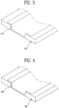
FIG. 3 is a perspective view illustrating a part of the bending jig illustrated inFIG. 2 . -
FIG. 4 is a perspective view illustrating a part of the base jig illustrated inFIG. 2 . -
FIG. 5 is a cross-sectional view illustrating a process of bending and forming a pouch by a pouch bending guide apparatus of a secondary battery packaging system using a stopping means in accordance with the present disclosure. -
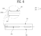
FIG. 6 is a cross-sectional view illustrating a state in which the bending jig illustrated inFIG. 5 is folded toward the base jig, and the stopping means supports the pouch to form a bending side of the pouch. -
FIG. 7 is a cross-sectional view illustrating a process of bending and forming a pouch by a pouch bending guide apparatus of a secondary battery packaging system using a stopping means in accordance with another embodiment of the present disclosure. -
FIG. 8 is a cross-sectional view illustrating a state in which the bending jig illustrated inFIG. 7 is folded toward the base jig, and the stopping means supports the pouch to form a bending side of the pouch. -
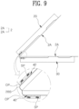
FIG. 9 is a cross-sectional view illustrating a process of bending and forming a pouch by a pouch bending guide apparatus of a secondary battery packaging system using a stopping means according to another embodiment of the present disclosure. -
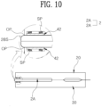
FIG. 10 is a cross-sectional view illustrating a state in which the bending jig illustrated inFIG. 9 is folded toward the base jig, and the stopping means supports the pouch to form a bending side of the pouch. -
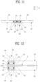
FIG. 11 is a cross-sectional view illustrating an unfolded state of a base jig and a bending jig which are main parts of a pouch bending guide apparatus of a secondary battery packaging system using a stopping means according to another embodiment of the present disclosure. -
FIG. 12 is a cross-sectional view schematically illustrating a state before the stopping means contact both sides of the pouch in a state where the bending jig shown inFIG. 11 is folded toward the base jig. -
FIG. 13 is a cross-sectional view schematically illustrating a state in which the stopping means are in contact with both sides of the pouch in a state where the bending jig illustrated inFIG. 12 is folded toward the base jig. - The present disclosure is a pouch bending guide apparatus of a secondary battery packaging system which folds a pouch sheet while a bending jig is folded toward a base jig in a state where the pouch sheet is disposed on the base jig and the bending jig, including a stopping means for preventing a bending side 2BS of a pouch from being pushed into the pouch by supporting at least one side of the
pouch 2 formed when the pouch sheet is folded by the bending jig, and the stopping means is best formed by a pad provided on the inner surface of the bending jig. - The present disclosure is a pouch bending guide apparatus of a secondary battery packaging system using a stopping means for preventing a bending side 2BS of a
pouch 2 from being pushed into thepouch 2 when thepouch sheet 2A is folded by thebending jig 20 being folded toward abase jig 30 in a state where thepouch sheet 2A is disposed on thebase jig 30 and thebending jig 20. The present disclosure is provided with a stopping means 42 as a main part. The stopping means 42 provided at least in the inside of thebending jig 20. The main feature is to prevent the bending side 2BS of thepouch 2 from being pushed into thepouch 2 by supporting the outer surface of thepouch 2 by the stopping means 42 when thepouch 2 is formed by a bending operation. In the present disclosure, when thepouch 2 is formed by bending thepouch sheet 2A, the stopping means 42 supports the battery cell accommodating part of thepouch 2 from the outside to prevent the bending side 2BS of thepouch 2 from being pushed into thepouch 2, and since the battery cell accommodating part of thepouch 2 is a configuration of thepouch 2, it will be understood that the stopping means 42 supports thepouch 2 from the outside. - The
bending jig 20 is supported by the support frame and at the same time is folded into the inner surface of thebase jig 30 by a bending driving unit and unfolded outward from the inner surface of thebase jig 30. A concave half-fold pouch battery cell accommodating part seating groove is also provided on the inner surface of thebending jig 20. The pouch battery cell accommodating part seating groove of thebending jig 20 also has a rectangular groove shape. - The
base jig 30 is mounted on a support frame, and one side wall of thebase jig 30 and thebending jig 20 is connected to each other by a hinge part. Thebending jig 20 is folded toward the inner surface of the base jig 30 so that the inner surface of thebase jig 30 and thebending jig 20 face each other, and thebending jig 20 is unfolded outward from the inner surface of thebase jig 30. Thebase jig 30 and thebending jig 20 are configured in a plate shape having a pouch battery cell accommodating part seating groove therein. Based on the hinge portion, thebending jig 20 is folded toward thebase jig 30 and unfolded from thebase jig 30. - In a state where the
bending jig 20 is unfolded from thebase jig 30, the inner surface of thebending jig 20 faces upward. - Preferably, a vacuum suction passage is provided inside the
base jig 30 and thebending jig 20, and a plurality of vacuum suction holes communicating with the vacuum suction passage are provided on inner surfaces of thebase jig 30 and thebending jig 20 facing each other. The vacuum suction hole of thebase jig 30 is opened to the inner surface of thebase jig 30 while being connected to the internal vacuum suction passage of thebase jig 30 . In addition, the vacuum suction hole of thebending jig 20 is also opened to the inner surface of thebending jig 20 while being connected to the internal vacuum suction passage of thebending jig 20. - The base jig 30 and the outer surface of the
pouch sheet 2A placed on the inner surface of thebending jig 20 are disposed to face the vacuum suction hole of thebase jig 30 and the vacuum suction hole of thebending jig 20. - The vacuum suction passage and the vacuum suction hole inside the
base jig 30 and the vacuum suction passage and the vacuum suction hole inside thebending jig 20 are connected to a vacuum device (not shown) by a connecting hose, avacuum connection block 42 and a vacuum pressure filling block 51. By sucking air through the vacuum suction hole on the inner surface of thebase jig 30 and the vacuum suction hole on the inner surface of thebending jig 20 by a vacuum device, thepouch sheet 2A can be closely adhered to the inner surface of thebase jig 30 and the inner surface of thebending jig 20 by vacuum. - A vacuum device is connected to the vacuum suction passage of the
base jig 30 and thebending jig 20 by a connecting means such as a hose not shown, so that thebending jig 20 is configured to fold toward thebase jig 30 based on the hinge part or unfold based on the hinge part in a state where the base jig 30 and thebending jig 20 adsorb thepouch sheet 2A by the operation of the vacuum device. The operation of folding or unfolding thebending jig 20 on thebase jig 30 may be performed by a bending operation means not shown. Since the bending operation means may use a known device such as a cylinder, a detailed description thereof will be omitted. - A
pouch sheet 2A is disposed on thebase jig 30 and thebending jig 20, a battery cell is accommodated in a half-fold battery cell accommodating part disposed on thebase jig 30 among a pair of half-fold battery cell accommodating parts of thepouch sheet 2A, and in a state where the two half-fold battery cell accommodating parts of thepouch sheet 2A are seated in the pouch battery cell accommodating part seating groove inside eachbase jig 30 and the pouch battery cell accommodating part seating groove of thebending jig 20, as thebending jig 20 is folded toward thebase jig 30, thepouch sheet 2A is folded, and thepouch sheet 2A is folded to form apouch 2 in which a battery cell is embedded in an internal battery cell accommodating part. - One side walls of the
base jig 30 and thebending jig 20 are connected to each other by a hinge part, and a bending guide opening part OP communicating with the inner and outer surfaces are formed on one sidewalls of thebase jig 30 and thebending jig 20. The bending guide opening part OP is also formed on one side wall of thebase jig 30, and is also formed on one side wall of the bendingjig 20. In other words, the bending guide opening part PO formed on one side walls of thebase jig 30 and the bendingjig 20 communicates with one side wall of thebase jig 30 and one side wall of the bendingjig 20 from one side of the pouch battery cell accommodating part seating groove formed in thebase jig 30 and the bendingjig 20, respectively. The bending guide opening part OP guides the bending side 2BS of thepouch 2 to be pushed out when the stopping means 42 pushes thepouch 2 from the outside, and may be referred to as a guide hole for preventing the bending side 2BS of thepouch 2 from being pushed concavely into thepouch 2. - The stopping means 42 supports at least one side of the
pouch 2 formed when thepouch sheet 2A is folded by the bendingjig 20 so as to prevent the bending side 2BS of thepouch 2 from being pushed into thepouch 2. The stopping means 42 is formed of a pad provided on the inner surface of the bendingjig 20. The stopping means 42 is formed of an elastic material such as a foamed urethane pad. - The stopping means 42 is configured in the shape of a square pad. The width between the left and right side ends of the stopping means 42 is equal to or slightly smaller than the width between the left and right side ends of the bending guide opening part OP.
- A half-fold pouch battery cell accommodating part seating groove is provided inside the bending
jig 20, and a pad-shaped stopping means 42 is provided at the inner bottom part of the half-fold pouch battery cell accommodating part seating groove. - The
base jig 30 is also provided with a half-fold pouch battery cell accommodating part seating groove therein. - When the bending
jig 20 is folded toward thebase jig 30 based on the hinge part of one side, the half-fold pouch battery cell accommodating part seating groove inside the bendingjig 20 and the half-fold pouch battery cell accommodating part seating groove inside thebase jig 30 face each other, and the pad-shaped stopping means 42 is disposed on the inner inner surface of the half-fold pouch battery cell accommodating part seating groove of the bendingjig 20, and in a state where the bendingjig 20 is folded toward thebase jig 30, the stopping means 42 is disposed at a position facing the internal inner surface of the half-fold pouch battery cell accommodating part seating groove of thebase jig 30. - In addition, the present disclosure provide a pouch bending method for a secondary battery packaging system using a stopping means including a pouch bending operation for folding a
pouch sheet 2A while a bendingjig 20 is folded toward abase jig 30 in a state where thepouch sheet 2A is disposed on thebase jig 30 and the bendingjig 20, and a pouch support operation for preventing a bending side 2BS of apouch 2 formed during the bending operation of thepouch sheet 2A from being pushed into thepouch 2, by a stopping means pushing at least one side of thepouch 2 from outside when thepouch sheet 2A is folded by the bendingjig 20. - According to the present disclosure having the above configuration, at least the bending
jig 20 is provided with the stopping means 42, and when thepouch sheet 2A is folded by the bendingjig 20, by supporting at least one side of thepouch 2 from the outside by the stopping means 42, the bending side 2BS of thepouch 2 is prevented from being pushed into the inside of thepouch 2. - Here, the stopping means 42 is formed of a pad of elasticity having a certain area, and the physical properties of the stopping means 42 are configured to have elasticity to the extent that it is not deformed when the
pouch 2 is bent and can be contracted when the jelly roll is put into thepouch 2. - In the present disclosure, the function of the stopping means 42 is to prevent the
pouch 2 from being pushed into the inside of the bending side 2BS by pressing thepouch 2 when only thepouch 2 is bent. - However, in a state where the battery cell (jelly roll) is put into the
pouch 2, thepouch 2 and the battery cell are subjected to force in the thickness direction by the stopping means 42, so that thepouch 2 is crushed or marks are formed. - Therefore, in the case of bending only the
pouch 2 in order to properly stop, the stopping means 42 protrudes from the inner surfaces of thebase jig 30 and the bendingjig 20, and when the battery cell is put into thepouch 2, the stopping means 42 has a function of retracting inward. In the present disclosure, when thepouch 2 is bent when the battery cells are put into thepouch 2, a spring SP or acylinder 60 is employed to prevent thepouch 2 from press marks or being crushed. This will be described later. - The
base jig 30 and the bendingjig 20 are unfolded based on the hinge part connected to each other, an on the inner surface of thebase jig 30 and the bendingjig 20, thepouch sheet 2A is unfolded, and each half-fold battery cell accommodating part of thepouch sheet 2A is seated in the half-fold pouch battery cell accommodating part seating groove inside the bendingjig 20 and at the same time the stopping means 42 is interposed between the outer surface of the half-fold battery cell accommodating part of thepouch sheet 2A and the internal inner surface of the half-fold pouch battery cell accommodating seating groove inside the bendingjig 20, and at the same time, the remaining half-fold battery cell accommodating part of thepouch sheet 2A is seated in the half-fold pouch battery cell accommodating part seating groove inside thebase jig 30, and in this state, when the bendingjig 20 is folded toward thebase jig 30 based on the hinge part, thepouch sheet 2A is also folded in half from the unfolded state. This is the pouch bending operation. - In a state in which the bending
jig 20 and thehalf-fold pouch sheet 2A are folded toward thebase jig 30 and the otherhalf-fold pouch sheet 2A, the stopping means 42 provided in the bendingjig 20 is supporting the half-fold battery cell accommodating part of thepouch 2 from the outside, and at the same time, the internal inner surface of the half-fold pouch battery cell accommodating part seating groove of thebase jig 30 supports the other half pouch battery cell accommodation part of thepouch 2 from the outside. - Accordingly, since the stopping means 42 supports at least one side of the pouch 2 (i.e., at least one side among both sides of the battery cell accommodating part of the pouch 2) from the outside, the bending side 2BS of the
pouch 2 is not pushed inward. Here, the bending guide opening part OP communicating with the inner and outer surfaces are formed on one side walls of thebase jig 30 and the bendingjig 20, and since the stopping means 42 supports at least one side of the pouch 2 (i.e., at least one side among both sides of the battery cell accommodating part of the pouch 2), a case in which the bending side 2BS of thepouch 2 is pushed inward can be prevented while a force to unfold outwardly of thepouch 2 acts through the bending guide opening part OP. In other words, since the stopping means 42 supports at least one side of thepouch 2 from the outside, thepouch 2 is formed in a state where the bending side 2BS of thepouch 2 is not pushed inward. The bendingjig 20 and thehalf-fold pouch sheet 2A are completely folded toward thebase jig 30 and the otherhalf-fold pouch sheet 2A, so that thepouch 2 in which the twohalf-fold pouch sheets 2A are overlapped can be formed. - Therefore, the present disclosure prevents the case where the middle portion of the
pouch sheet 2A is pushed inward during the bending operation of folding the middle portion of thepouch sheet 2A so as to solve the problem that the bending side 2BS of thepouch 2 is deformed concavely inward. In other words, it solves a problem such as when thepouch sheet 2A is folded, the bending side surface 2BS of thepouch 2 goes inside and is concavely crushed. - Conventionally, in the case of a battery without a bottom, when the
pouch 2 is bent, thepouch 2 enters the main room, resulting in a smaller size of the main room. - However, in the present disclosure, the
pouch 2 is folded in half with thepouch sheet 2A in a state (in the present invention, a state where two stoppingmeans 42 support both sides of the pouch 2) where at least one side of thepouch 2 is supported by the stopping means 42 with an adequate elastic force (adequate elastic force of the spring 62) to prevent thepouch 2 from entering the main room. The fact that thepouch 2 enters the main room means that when thepouch sheet 2A is folded to form thepouch 2, the bending side 2BS of one side of thepouch 2 is pushed into the interior of thepouch 2, and the present disclosure solves the problem that the main room size of thepouch 2 becomes smaller by preventing thepouch 2 from entering the main room during bending of thepouch 2 as described above. - Since the bending side 2BS of the
pouch 2 is not pushed in, the external quality of thepouch 2 is improved and the reliability of thepouch 2 is improved. - In addition, when the bending side 2BS of the
pouch 2 with built in battery cells is deformed to be concave inward, the problem that the heat generated during the charging/discharging operation of the secondary battery is not properly discharged is also solved. A plurality ofpouches 2 with built in battery cells (hereinafter, referred to aspouch 2 for convenience) are placed side by side on a hanger frame and mounted, and the bending side 2BS of thepouch 2 is in contact with the heat sink provided at the bottom of the hanger frame, and the heat generated in thepouch 2 during the battery cell charging/discharging operation is conducted from the bending side 2BS to the heat sink, and discharged, wherein the bending side 2BS of thepouch 2 does not have a concave deformed part that is concave inward, so it is not that the concave deformed part of thepouch 2 does not properly contact the heat sink, but rather because the bending side 2BS of thepouch 2 protrudes more or is formed flat at least from the side of thepouch 2, the bending side 2BS of thepouch 2 is firmly in contact with the heat sink, resulting in the effect of properly dissipating the heat generated inside thepouch 2 during the battery cell charging/discharging operation by properly transferring the heat generated in thepouch 2 from the bending side 2BS to the heat sink during the battery cell charging/discharging operation. - In addition, as heat is properly dissipated from the
pouch 2, there is an effect of solving the problem that the battery cells are deteriorated or burned out due to heat. - Meanwhile,
FIGS. 5 and6 show another embodiment of the present disclosure. In another embodiment of the present disclosure illustrated inFIGS. 5 and6 , the stopping means 42 is also provided inside thebase jig 30 to which the bendingjig 20 is connected via a hinge part. A pad-shaped stopping means 42 is also provided on the internal inner surface of the pouch battery cell accommodating part seating groove inside thebase jig 30. In a state in which the bendingjig 20 is folded toward thebase jig 30 based on the hinge part, two pad-shaped stopping means 42 are disposed at positions facing each other. - According to another embodiment of the present disclosure, both the bending
jig 20 and thebase jig 30 are provided with the stopping means 42, and by supporting both sides of thepouch 2 from the outside by the two stoppingmeans 42 when thepouch sheet 2A is folded by the bendingjig 20, the bending side 2BS of thepouch 2 is prevented from being pushed into the inside of thepouch 2. - When the bending
jig 20 is folded toward thebase jig 30 based on the hinge part, thepouch sheet 2A is also folded in half from the unfolded state, and the stopping means 42 provided in the bendingjig 20 is supporting the half-fold battery cell accommodating part of thepouch 2 from the outside in a state where the bendingjig 20 and thehalf-fold pouch sheet 2A are folded toward thebase jig 30 and the otherhalf-fold pouch sheet 2A, and at the same time, the other stopping means 42 provided on the internal inner surface of the seating groove of the half-fold pouch battery cell accommodating part of thebase jig 30 also supports the other half-fold pouch battery cell accommodating part of thepouch 2 from the outside. - Therefore, since the stopping means 42 supports both sides of the pouch 2 (i.e., both sides of the battery cell accommodating part of the pouch 2) from the outside, the bending side 2BS of the
pouch 2 is not pushed inward. Here, the bending guide opening part OP communicating with the inner and outer surfaces are formed on one side walls of thebase jig 30 and the bendingjig 20, and since the stopping means 42 supports both sides of the pouch 2 (i.e., both sides of the battery cell accommodating part of the pouch 2), a case in which the bending side 2BS of thepouch 2 is pushed inward can be prevented while a force to unfold outwardly of thepouch 2 acts through the bending guide opening part OP. In other words, since the stopping means 42 supports both sides of thepouch 2 from the outside, thepouch 2 is formed in a state where the bending side 2BS of thepouch 2 is not pushed inward. - Since the effects of other embodiments of the present disclosure are the same as the effects of the above-described embodiments of the present disclosure, redundant descriptions thereof will be omitted. However, in another embodiment of the present disclosure, since the two stopping
means 42 support both sides of thepouch 2 from the outside, there is an effect of more reliably preventing the case where the bending side of thepouch 2 is pushed into the inner surface of thepouch 2. - In the above embodiment, only the
pouch 2 is bent in a state where the battery cell (jelly roll) is not put into thepouch 2, when only thepouch 2 is bent, the stopping means 42 presses thepouch 2 to prevent it from being pushed into the inside of the bending side 2BS of thepouch 2. Refer toFIGS. 5 to 8 . - On the other hand, in the present disclosure, when the battery cells are put into the
pouch 2, the stopping means 42 is configured to have a function of retracting inward. In the present disclosure, a spring SP or acylinder 60 is employed so that the stopping means 42 has a function of retracting inward. -
FIGS. 9 and10 illustrate an embodiment in which a spring SP is employed to prevent thepouch 2 from press marks or the pouch from being crushed when thepouch 2 is bent in a state where the battery cell (jelly roll) is put in thepouch 2 in the present disclosure. - According to the present disclosure illustrated in
FIGS. 9 and10 , the stopping means 42 is slidably embedded in the push operation hole formed in the bendingjig 20, and a spring SP is interposed between the push operation hole and the stopping means 42, and it is configured such that the stopping means 42 can be retracted inward from thepouch 2 while the spring SP is supporting the stoppingmeans 42. - When forming the
pouch 2 by folding the bendingjig 20 toward thebase jig 30 in a state where the battery cell is built in thepouch 2, as the stopping means 42 is pushed into the inside of the bendingjig 20 and thebase jig 30 from thepouch 2, the spring SP is pressed, and since the force pressing in the thickness direction of thepouch 2 does not act and a pair of stoppingmeans 42 support both sides of thepouch 2 from the outside, in the process of bending thepouch 2, the bending side 2BS is prevented from being pushed into the inside of thepouch 2, and at the same time, thepouch 2 is prevented from press marks or thepouch 2 is prevented from being crushed. - In other words, in the embodiment employing the spring SP in the present disclosure, when the
pouch 2 is bent in the state where the battery cell (jelly roll) is put in thepouch 2, the stopping means 42 is pushed in from thepouch 2 so as to prevent the bending side 2BS of thepouch 2 from being pushed into the inside of thepouch 2 as well as to prevent thepouch 2 from press marks or thepouch 2 being crushed. In other words, the embodiment of the present disclosure illustrated inFIGS. 9 and10 employs a spring SP so that proper stopping occurs when thepouch 2 is bent in a state where the battery cells are put into thepouch 2. - In addition,
FIGS. 11 to 13 illustrate an embodiment in which thecylinder 60 is employed to prevent thepouch 2 from press marks or thepouch 2 from being crushed when thepouch 2 is bent in a state where a battery cell (jelly roll) is put into thepouch 2 in the present disclosure. - In the present invention illustrated in
FIGS. 11 to 13 , at least one of thebase jig 30 and the bendingjig 20 is provided with the stopping means 42, and the stopping means 42 supports at least one side of thepouch 2 from the outside, and the stopping means 42 is configured to be connected to the cylinder rod of thecylinder 60. In the present disclosure, two pad-shaped stopping means 42 are disposed on the internal inner surface of the half-fold pouch battery cell accommodating part seating groove inside thebase jig 30 and the bendingjig 20, and the two stoppingmeans 42 are configured to be connected to the cylinder rods of the twocylinders 60. - Among the
base jig 30 and the bendingjig 20, at least the bendingjig 20 is provided with thecylinder 60. Thecylinder 60 is mounted on the outer surface of the bendingjig 20. The inside of the bendingjig 20 is provided with a push operation hole. The push operation hole may be configured to communicate from the inner surface to the outer surface of the bendingjig 20. The push operation hole may be configured in a cross-sectional rectangular hole shape. In the present disclosure, acylinder 60 is provided in each of thebase jig 30 and the bendingjig 20, and a push operation hole is provided in thebase jig 30 and the bendingjig 20. The push operation hole on thebase jig 30 side communicates with the inner surface from the inside of thebase jig 30, and the push operation hole on the bendingjig 20 side communicates with the inner surface from the inside of the bendingjig 20. - The stopping means 42 is coupled to the push operation hole of the
base jig 30 and the bendingjig 20 so as to move forward and backward. The stopping means 42 are configured to move forward toward the inner surface of thebase jig 30 and the inner surface of the bendingjig 20 in each push operation hole. The stopping means 42 is formed in a plate shape. When the push operation hole has a cross-sectional square hole shape, the stopping means 42 is configured in a square plate shape. - A
guide bar 52 is built in the push operation hole. A plurality of guide bars 52 are disposed in the push operation hole. - A
push operation plate 64 is connected to the cylinder rod provided in thecylinder 60 on thebase jig 30 side and the cylinder rod provided in thecylinder 60 on the bendingjig 20 side, respectively, and thepush operation plate 64 is slidably coupled to theguide bar 52. Thepush operation plate 64 is disposed at a position facing the stoppingmeans 42. - The cylinder rods of the
cylinders 60 provided in thebase jig 30 and the bendingjig 20 are connected to thepush operation plate 64. - The stopping means 42 is connected to the
push operation plate 64. The stopping means 42 is connected to thepush operation plate 64 via a connecting means such as a connecting bar (not shown). - A
spring 62 is interposed between thepush operation plate 64 and the stoppingmeans 42. Thespring 62 is interposed between thepush operation plate 64 and the stopping means 42 in a state of being coupled to the outer circumferential surface of theguide bar 52. Aspring 62 is interposed between the bottom surface of thepush operation plate 64 and the top surface of the stoppingmeans 42. When the cylinder rod of thecylinder 60 moves forward, thepush operation plate 64 and the stopping means 42 move forward, and when the cylinder rod of thecylinder 60 moves backward, thepush operation plate 64 and the stopping means 42 moves backward. In a state in which thepush operation plate 64 and the stopping means 42 are moved forward, thespring 62 is compressed to retain elastic restoring force, and in a state where thepush operation plate 64 and the stopping means 42 are moved backward, thespring 62 is unfolded. - According to another embodiment of the present disclosure illustrated in
FIGS. 11 to 13 , at least the bendingjig 20 is provided with the stopping means 42, and when thepouch sheet 2A is folded by the bendingjig 20, by supporting at least one side of thepouch 2 from the outside by the stopping means 42, the bending side 2BS of thepouch 2 is prevented from being pushed into the inside of thepouch 2. In the present disclosure, each of thebase jig 30 and the bendingjig 20 is provided with the stopping means 42, and the two stoppingmeans 42 are configured to support both sides of thepouch 2 from the outside. - Specifically, the
base jig 30 and the bendingjig 20 are unfolded based on the hinge part connected to each other, and on the inner surface of thebase jig 30 and the bendingjig 20, thepouch sheet 2A is unfolded, and in such a state, when the bendingjig 20 is folded toward thebase jig 30 based on the hinge part, thepouch sheet 2A is also folded in half from the unfolded state. - In a state in which the bending
jig 20 and thehalf-fold pouch sheet 2A are folded toward thebase jig 30 and the otherhalf-fold pouch sheet 2A, the cylinder rods of thecylinder 60 provided in thebase jig 30 and the bendingjig 20 move forward and thepush operation plate 64 and the stopping means 42 move forward, so that the two stoppingmeans 42 support both sides of thepouch 2 from the outside. Here, thespring 62 is compressed to have an elastic restoring force. - Then, since the stopping means 42 support both sides of the
pouch 2 from the outside, the bending side 2BS of thepouch 2 is not pushed inward. Here, a bending guide opening part OP communicating with the inner and outer surfaces is formed on one side walls of thebase jig 30 and the bendingjig 20, and since the stopping means 42 support both sides of thepouch 2, a case in which the bending side 2BS of thepouch 2 is pushed inward can be prevented while a force to unfold outwardly of thepouch 2 acts through the bending guide opening part OP. Since the stopping means 42 supports both sides of thepouch 2 from the outside, thepouch 2 is formed in a state where the bending side 2BS of thepouch 2 is not pushed inward. The bendingjig 20 and thehalf-fold pouch sheet 2A are completely folded toward thebase jig 30 and the otherhalf-fold pouch sheet 2A, so that thepouch 2 in which the twohalf-fold pouch sheets 2A are overlapped can be formed. - On the other hand, while the
spring 62 is compressed to retain elastic restoring force, the elastic restoring force of thespring 62 is such that the force of the stopping means 42 pressing thepouch 2 inward is not applied and in a state where the stopping means 42 elastically holds the elastic restoring force enough to support both sides of thepouch 2 from the outside, when the stopping means 42 presses both sides of thepouch 2 with excessive force, it is possible to prevent thepouch 2 from being press marks or thepouch 2 from being crushed. - As illustrated in
FIGS. 11 to 13 , even in the present disclosure employing thecylinder 60, since the stopping means 42 is pushed inward from thepouch 2 and the force pressed by the stopping means 42 in the thickness direction of thepouch 2 does not act in the state in which the battery cell (jelly roll) is put in thepouch 2, thepouch 2 is prevented from press marks or being crushed. The embodiment of the present disclosure illustrated inFIGS. 11 to 13 also employs acylinder 60 to properly stop thepouch 2 when bending thepouch 2 in a state where the battery cells are put into. - On the other hand, since the force of supporting the
pouch 2 from the outside by stoppingmeans 42 can be adjusted by adjusting the force of the cylinder rod of thecylinder 60 to move forward, there is an effect of more reliably preventing thepouch 2 from getting press marks by the stopping means or thepouch 2 from being crushed, and there is an effect that the clearance of the stopping means 42 can be easily and quickly adjusted by thecylinder 60 in response to the thickness of thepouch 2. By adjusting the clearance of the stopping means 42 corresponding to the thickness of thepouch 2, there is an effect that it can be used interchangeably even if the thickness of thepouch 2 is different. - A pouch bending guide apparatus of a secondary battery packaging system using a stopping means according to the present disclosure, is a pouch bending guide apparatus of a secondary battery packaging system which folds a pouch sheet while a bending jig is folded toward a base jig in a state where the pouch sheet is disposed on the base jig and the bending jig, including a stopping means for preventing a bending side 2BS of a pouch from being pushed into the pouch by supporting at least one side of the
pouch 2 formed when the pouch sheet is folded by the bending jig, which has industrial applicability.
Claims (11)
- A pouch bending guide apparatus of a secondary battery packaging system using a stopping means, which folds a pouch sheet 2A while a bending jig 20 is folded toward a base jig 30 in a state where the pouch sheet 2A is disposed on the base jig 30 and the bending jig 20, characterized by comprising:
a stopping means 42 for preventing a bending side 2BS of a pouch 2 from being pushed into the pouch 2 by supporting at least one side of the pouch 2 formed when the pouch sheet 2A is folded by the bending jig 20. - The pouch bending guide apparatus of claim 1, characterized in that the stopping means 42 is formed of a pad provided on an inner surface of the bending jig 20.
- The pouch bending guide apparatus of claim 2, characterized in that the stopping means 42 is also provided inside the base jig 30 to which the bending jig 20 is connected via a hinge part.
- The pouch bending guide apparatus of claim 2, characterized in that the stopping means 42 is slidably embedded in a push operation hole formed in the bending jig 20, and a spring SP is interposed between the push operation hole and the stopping means 42, so that the stopping means 42 is configured to adjust a clearance according to a thickness of the pouch in a state where the spring SP supports the stopping means 42.
- The pouch bending guide apparatus of claim 2, characterized in that the stopping means 42 is also provided inside the base jig 30 to which the bending jig 20 is connected via a hinge part, the stopping means 42 is slidably embedded in a push operation hole formed in the bending jig 20 and the base jig 30, and a spring SP is interposed between the push operation hole and the stopping means 42, so that the stopping means 42 is configured to adjust a clearance according to a thickness of the pouch in a state where the spring SP supports the stopping means 42.
- The pouch bending guide apparatus of claim 1, characterized by comprising:
a cylinder 60 for moving the stopping means 42 back and forth. - The pouch bending guide apparatus of claim 1, characterized in that the stopping means 42 is provided inside each of the base jig 30 and the bending jig 20, and when forming the pouch 2 by folding the pouch sheet 2A, the stopping means 42 on the base jig 30 side and the stopping means 42 on the bending jig 20 side are configured to support outer both surfaces of the pouch 2.
- The pouch bending guide apparatus of claim 7, characterized in that a cylinder 60 is provided outside each of the base jig 30 and the bending jig 20, to push the stopping means 42 on the base jig 30 side and the stopping means 42 on the bending jig 20 side.
- The pouch bending guide apparatus of claim 8, characterized in that the cylinder 60 is provided on outer surface opposite to an inner surface of each of the base jig 30 and the bending jig 20, a cylinder rod of the cylinder 60 is provided with a push operation plate 64 slidably coupled to a push operation hole, a guide bar 52 built in the push operation hole is coupled to the push operation plate 64, and the stopping means 42 is connected to the push operation plate 64.
- The pouch bending guide apparatus of claim 1, characterized in that one side wall of the base jig 30 and one side wall of the bending jig 20 are connected to each other by a hinge part, and a bending guide opening part OP is formed on the one side wall of the base jig 30 and the one side wall of the bending jig 20 to communicate with inner and outer surfaces.
- A pouch bending method for a secondary battery packaging system using a stopping means, characterized by comprising:a pouch bending operation for folding a pouch sheet 2A while a bending jig 20 is folded toward a base jig 30 in a state where the pouch sheet 2A is disposed on the base jig 30 and the bending jig 20; anda pouch support operation for preventing a bending side 2BS of a pouch 2 formed during the bending operation of the pouch sheet 2A from being pushed into the pouch 2, by a stopping means 42 pushing at least one side of the pouch 2 from outside when the pouch sheet 2A is folded by the bending jig 20.
Applications Claiming Priority (2)
| Application Number | Priority Date | Filing Date | Title |
|---|---|---|---|
| KR1020200040220A KR102304208B1 (en) | 2020-04-02 | 2020-04-02 | Battery cell pouch bending apparaus for secondary battery packaging system utilizing stopping means and pouch bending method |
| PCT/KR2020/008048 WO2021201338A1 (en) | 2020-04-02 | 2020-06-22 | Pouch bending guide apparatus and pouch bending method for secondary battery packaging system using stopping means |
Publications (3)
| Publication Number | Publication Date |
|---|---|
| EP4129623A1 true EP4129623A1 (en) | 2023-02-08 |
| EP4129623A4 EP4129623A4 (en) | 2024-04-03 |
| EP4129623B1 EP4129623B1 (en) | 2025-02-26 |
Family
ID=77914485
Family Applications (1)
| Application Number | Title | Priority Date | Filing Date |
|---|---|---|---|
| EP20928648.3A Active EP4129623B1 (en) | 2020-04-02 | 2020-06-22 | Pouch bending guide apparatus and pouch bending method for secondary battery packaging system using stopping means |
Country Status (6)
| Country | Link |
|---|---|
| US (1) | US20230191467A1 (en) |
| EP (1) | EP4129623B1 (en) |
| KR (1) | KR102304208B1 (en) |
| HU (1) | HUE071326T2 (en) |
| PL (1) | PL4129623T3 (en) |
| WO (1) | WO2021201338A1 (en) |
Families Citing this family (1)
| Publication number | Priority date | Publication date | Assignee | Title |
|---|---|---|---|---|
| CN114497677A (en) * | 2022-01-18 | 2022-05-13 | 中山市众旺德新能源科技有限公司 | A kind of manufacturing method of double pit soft pack battery |
Family Cites Families (14)
| Publication number | Priority date | Publication date | Assignee | Title |
|---|---|---|---|---|
| US2696241A (en) * | 1950-07-03 | 1954-12-07 | Northrop Aircraft Inc | Wrap-stretch means |
| US4713957A (en) * | 1986-08-12 | 1987-12-22 | Eder Ernest J | Reverse bend attachment for a sheet metal brake |
| JP3594567B2 (en) * | 2001-05-21 | 2004-12-02 | アスカ電子株式会社 | Battery holder |
| US8875554B2 (en) * | 2011-10-19 | 2014-11-04 | Ford Global Technologies, Llc | Hemming a flange with compression to form a sharp edge |
| KR20130048419A (en) | 2011-11-02 | 2013-05-10 | 에스케이이노베이션 주식회사 | Secondary battery in pouch type |
| KR101571210B1 (en) * | 2013-09-04 | 2015-11-23 | 주식회사 엘지화학 | Jig apparatus for secondary battery |
| KR20150003358U (en) | 2014-03-03 | 2015-09-11 | 주식회사 엘지화학 | Secondary Battery Pouch |
| KR101758959B1 (en) * | 2014-06-10 | 2017-07-17 | 주식회사 엘지화학 | Jig device for battery cell |
| KR101672402B1 (en) * | 2015-07-21 | 2016-11-03 | (주)휴민텍 | Acute angle bending apparatus for side sealing portion of pouch type secondary battery cell and acute angle bending method using the same |
| KR101858680B1 (en) * | 2016-08-11 | 2018-05-16 | (주)테크랜드 | Apparatus and method for folding cells of secondary cell battery |
| KR102169839B1 (en) * | 2016-09-08 | 2020-10-26 | 주식회사 엘지화학 | Battery Case Sealing Device Having Wrinkle Removal Function |
| KR102217451B1 (en) * | 2017-08-29 | 2021-02-22 | 주식회사 엘지화학 | Rechargeable battery and the manufacturing method, and press block for rechargeable battery |
| DE102017120192A1 (en) * | 2017-09-01 | 2019-03-07 | Benteler Automobiltechnik Gmbh | Hold-down press for producing a semifinished product from sheet material with thinned areas and method for producing a Blechumformbauteils |
| KR101903367B1 (en) * | 2017-10-26 | 2018-10-02 | 주식회사 디에이테크놀로지 | Protection Film Packaging Apparatus for Secondary Cell |
-
2020
- 2020-04-02 KR KR1020200040220A patent/KR102304208B1/en active Active
- 2020-06-22 EP EP20928648.3A patent/EP4129623B1/en active Active
- 2020-06-22 PL PL20928648.3T patent/PL4129623T3/en unknown
- 2020-06-22 WO PCT/KR2020/008048 patent/WO2021201338A1/en not_active Ceased
- 2020-06-22 HU HUE20928648A patent/HUE071326T2/en unknown
- 2020-06-22 US US17/916,754 patent/US20230191467A1/en active Pending
Also Published As
| Publication number | Publication date |
|---|---|
| KR102304208B9 (en) | 2023-01-13 |
| US20230191467A1 (en) | 2023-06-22 |
| PL4129623T3 (en) | 2025-06-02 |
| KR102304208B1 (en) | 2021-09-24 |
| EP4129623B1 (en) | 2025-02-26 |
| HUE071326T2 (en) | 2025-08-28 |
| WO2021201338A1 (en) | 2021-10-07 |
| EP4129623A4 (en) | 2024-04-03 |
Similar Documents
| Publication | Publication Date | Title |
|---|---|---|
| US12057545B2 (en) | Pouch exterior material for secondary battery, pouch type secondary battery using the same, and method of manufacturing the same | |
| KR101962526B1 (en) | Pressurization device for battery cells | |
| CN110311068A (en) | Battery | |
| US7816029B2 (en) | Battery module | |
| US11539068B2 (en) | Method for manufacturing secondary battery | |
| EP4129623B1 (en) | Pouch bending guide apparatus and pouch bending method for secondary battery packaging system using stopping means | |
| CN110603665A (en) | Electrolyte removing device, apparatus and method for manufacturing secondary battery including the same, and secondary battery | |
| US11870082B2 (en) | Method for manufacturing secondary battery | |
| US20230163343A1 (en) | Battery cell pouch bending apparatus for secondary battery packaging system and pouch bending method | |
| CN114128077A (en) | Apparatus for charging and discharging secondary battery | |
| CN117321842A (en) | Battery pack and vehicle including the same | |
| JP2003031264A (en) | Thin plate bending method and apparatus, and method of manufacturing lithium ion secondary battery | |
| US20230187684A1 (en) | Method for Manufacturing Secondary Battery and Apparatus for Manufacturing Secondary Battery | |
| KR102757190B1 (en) | Jig unit, degas device and degas method including thereof | |
| JP7567137B2 (en) | Pouch Sealing Machine | |
| JP7482999B2 (en) | Battery module manufacturing apparatus and battery module manufacturing method | |
| US20240154147A1 (en) | Apparatus for Manufacturing Pouch Type Rechargeable-Battery | |
| JP2024531531A (en) | Pouch manufacturing equipment | |
| US12463234B2 (en) | Formation device of pouch-type battery cell | |
| JP7818624B2 (en) | Battery pack and manufacturing method thereof | |
| JP2026511644A (en) | Battery cell pressurizing jig and battery cell gas removal system including the same | |
| CN118786574A (en) | Electrolyte injection device for battery cells | |
| KR20230127912A (en) | Pouch folding device for secondary battery and secondary battery | |
| JP2023011277A (en) | packaging method |
Legal Events
| Date | Code | Title | Description |
|---|---|---|---|
| STAA | Information on the status of an ep patent application or granted ep patent |
Free format text: STATUS: THE INTERNATIONAL PUBLICATION HAS BEEN MADE |
|
| PUAI | Public reference made under article 153(3) epc to a published international application that has entered the european phase |
Free format text: ORIGINAL CODE: 0009012 |
|
| STAA | Information on the status of an ep patent application or granted ep patent |
Free format text: STATUS: REQUEST FOR EXAMINATION WAS MADE |
|
| 17P | Request for examination filed |
Effective date: 20221031 |
|
| AK | Designated contracting states |
Kind code of ref document: A1 Designated state(s): AL AT BE BG CH CY CZ DE DK EE ES FI FR GB GR HR HU IE IS IT LI LT LU LV MC MK MT NL NO PL PT RO RS SE SI SK SM TR |
|
| RIN1 | Information on inventor provided before grant (corrected) |
Inventor name: PARK, SANG JUN Inventor name: KIM, WOOK KYOUNG Inventor name: AHN, JI EUN Inventor name: JEONG, BONG UK Inventor name: PARK, HUI JIN Inventor name: KO, KANG HO Inventor name: KIM, JONG SUNG |
|
| RAP1 | Party data changed (applicant data changed or rights of an application transferred) |
Owner name: SK ON CO., LTD. |
|
| DAV | Request for validation of the european patent (deleted) | ||
| DAX | Request for extension of the european patent (deleted) | ||
| A4 | Supplementary search report drawn up and despatched |
Effective date: 20240305 |
|
| RIC1 | Information provided on ipc code assigned before grant |
Ipc: B21D 11/20 20060101ALN20240228BHEP Ipc: H01M 50/183 20210101ALI20240228BHEP Ipc: H01M 50/20 20210101ALI20240228BHEP Ipc: H01M 10/04 20060101ALI20240228BHEP Ipc: B21D 19/08 20060101ALI20240228BHEP Ipc: B21D 19/12 20060101ALI20240228BHEP Ipc: B21D 19/02 20060101ALI20240228BHEP Ipc: B29C 53/80 20060101ALI20240228BHEP Ipc: H01M 50/10 20210101ALI20240228BHEP Ipc: B29C 53/04 20060101AFI20240228BHEP |
|
| GRAP | Despatch of communication of intention to grant a patent |
Free format text: ORIGINAL CODE: EPIDOSNIGR1 |
|
| STAA | Information on the status of an ep patent application or granted ep patent |
Free format text: STATUS: GRANT OF PATENT IS INTENDED |
|
| RIC1 | Information provided on ipc code assigned before grant |
Ipc: B21D 11/20 20060101ALN20240909BHEP Ipc: H01M 50/183 20210101ALI20240909BHEP Ipc: H01M 50/20 20210101ALI20240909BHEP Ipc: H01M 10/04 20060101ALI20240909BHEP Ipc: B21D 19/08 20060101ALI20240909BHEP Ipc: B21D 19/12 20060101ALI20240909BHEP Ipc: B21D 19/02 20060101ALI20240909BHEP Ipc: B29C 53/80 20060101ALI20240909BHEP Ipc: H01M 50/105 20210101ALI20240909BHEP Ipc: B29C 53/04 20060101AFI20240909BHEP |
|
| INTG | Intention to grant announced |
Effective date: 20240920 |
|
| GRAS | Grant fee paid |
Free format text: ORIGINAL CODE: EPIDOSNIGR3 |
|
| GRAA | (expected) grant |
Free format text: ORIGINAL CODE: 0009210 |
|
| STAA | Information on the status of an ep patent application or granted ep patent |
Free format text: STATUS: THE PATENT HAS BEEN GRANTED |
|
| AK | Designated contracting states |
Kind code of ref document: B1 Designated state(s): AL AT BE BG CH CY CZ DE DK EE ES FI FR GB GR HR HU IE IS IT LI LT LU LV MC MK MT NL NO PL PT RO RS SE SI SK SM TR |
|
| REG | Reference to a national code |
Ref country code: GB Ref legal event code: FG4D |
|
| REG | Reference to a national code |
Ref country code: CH Ref legal event code: EP |
|
| REG | Reference to a national code |
Ref country code: DE Ref legal event code: R096 Ref document number: 602020047027 Country of ref document: DE |
|
| REG | Reference to a national code |
Ref country code: IE Ref legal event code: FG4D |
|
| REG | Reference to a national code |
Ref country code: NL Ref legal event code: MP Effective date: 20250226 |
|
| PG25 | Lapsed in a contracting state [announced via postgrant information from national office to epo] |
Ref country code: RS Free format text: LAPSE BECAUSE OF FAILURE TO SUBMIT A TRANSLATION OF THE DESCRIPTION OR TO PAY THE FEE WITHIN THE PRESCRIBED TIME-LIMIT Effective date: 20250526 |
|
| PG25 | Lapsed in a contracting state [announced via postgrant information from national office to epo] |
Ref country code: FI Free format text: LAPSE BECAUSE OF FAILURE TO SUBMIT A TRANSLATION OF THE DESCRIPTION OR TO PAY THE FEE WITHIN THE PRESCRIBED TIME-LIMIT Effective date: 20250226 |
|
| PG25 | Lapsed in a contracting state [announced via postgrant information from national office to epo] |
Ref country code: ES Free format text: LAPSE BECAUSE OF FAILURE TO SUBMIT A TRANSLATION OF THE DESCRIPTION OR TO PAY THE FEE WITHIN THE PRESCRIBED TIME-LIMIT Effective date: 20250226 |
|
| REG | Reference to a national code |
Ref country code: LT Ref legal event code: MG9D |
|
| PG25 | Lapsed in a contracting state [announced via postgrant information from national office to epo] |
Ref country code: NO Free format text: LAPSE BECAUSE OF FAILURE TO SUBMIT A TRANSLATION OF THE DESCRIPTION OR TO PAY THE FEE WITHIN THE PRESCRIBED TIME-LIMIT Effective date: 20250526 Ref country code: IS Free format text: LAPSE BECAUSE OF FAILURE TO SUBMIT A TRANSLATION OF THE DESCRIPTION OR TO PAY THE FEE WITHIN THE PRESCRIBED TIME-LIMIT Effective date: 20250626 |
|
| PG25 | Lapsed in a contracting state [announced via postgrant information from national office to epo] |
Ref country code: NL Free format text: LAPSE BECAUSE OF FAILURE TO SUBMIT A TRANSLATION OF THE DESCRIPTION OR TO PAY THE FEE WITHIN THE PRESCRIBED TIME-LIMIT Effective date: 20250226 |
|
| PG25 | Lapsed in a contracting state [announced via postgrant information from national office to epo] |
Ref country code: HR Free format text: LAPSE BECAUSE OF FAILURE TO SUBMIT A TRANSLATION OF THE DESCRIPTION OR TO PAY THE FEE WITHIN THE PRESCRIBED TIME-LIMIT Effective date: 20250226 |
|
| PG25 | Lapsed in a contracting state [announced via postgrant information from national office to epo] |
Ref country code: LV Free format text: LAPSE BECAUSE OF FAILURE TO SUBMIT A TRANSLATION OF THE DESCRIPTION OR TO PAY THE FEE WITHIN THE PRESCRIBED TIME-LIMIT Effective date: 20250226 Ref country code: PT Free format text: LAPSE BECAUSE OF FAILURE TO SUBMIT A TRANSLATION OF THE DESCRIPTION OR TO PAY THE FEE WITHIN THE PRESCRIBED TIME-LIMIT Effective date: 20250626 |
|
| PGFP | Annual fee paid to national office [announced via postgrant information from national office to epo] |
Ref country code: HU Payment date: 20250616 Year of fee payment: 6 |
|
| PG25 | Lapsed in a contracting state [announced via postgrant information from national office to epo] |
Ref country code: BG Free format text: LAPSE BECAUSE OF FAILURE TO SUBMIT A TRANSLATION OF THE DESCRIPTION OR TO PAY THE FEE WITHIN THE PRESCRIBED TIME-LIMIT Effective date: 20250226 Ref country code: GR Free format text: LAPSE BECAUSE OF FAILURE TO SUBMIT A TRANSLATION OF THE DESCRIPTION OR TO PAY THE FEE WITHIN THE PRESCRIBED TIME-LIMIT Effective date: 20250527 |
|
| REG | Reference to a national code |
Ref country code: AT Ref legal event code: MK05 Ref document number: 1770235 Country of ref document: AT Kind code of ref document: T Effective date: 20250226 |
|
| REG | Reference to a national code |
Ref country code: HU Ref legal event code: AG4A Ref document number: E071326 Country of ref document: HU |
|
| PG25 | Lapsed in a contracting state [announced via postgrant information from national office to epo] |
Ref country code: SE Free format text: LAPSE BECAUSE OF FAILURE TO SUBMIT A TRANSLATION OF THE DESCRIPTION OR TO PAY THE FEE WITHIN THE PRESCRIBED TIME-LIMIT Effective date: 20250226 |
|
| PG25 | Lapsed in a contracting state [announced via postgrant information from national office to epo] |
Ref country code: SM Free format text: LAPSE BECAUSE OF FAILURE TO SUBMIT A TRANSLATION OF THE DESCRIPTION OR TO PAY THE FEE WITHIN THE PRESCRIBED TIME-LIMIT Effective date: 20250226 |
|
| PG25 | Lapsed in a contracting state [announced via postgrant information from national office to epo] |
Ref country code: DK Free format text: LAPSE BECAUSE OF FAILURE TO SUBMIT A TRANSLATION OF THE DESCRIPTION OR TO PAY THE FEE WITHIN THE PRESCRIBED TIME-LIMIT Effective date: 20250226 |
|
| PG25 | Lapsed in a contracting state [announced via postgrant information from national office to epo] |
Ref country code: IT Free format text: LAPSE BECAUSE OF FAILURE TO SUBMIT A TRANSLATION OF THE DESCRIPTION OR TO PAY THE FEE WITHIN THE PRESCRIBED TIME-LIMIT Effective date: 20250226 |
|
| PG25 | Lapsed in a contracting state [announced via postgrant information from national office to epo] |
Ref country code: AT Free format text: LAPSE BECAUSE OF FAILURE TO SUBMIT A TRANSLATION OF THE DESCRIPTION OR TO PAY THE FEE WITHIN THE PRESCRIBED TIME-LIMIT Effective date: 20250226 |
|
| PG25 | Lapsed in a contracting state [announced via postgrant information from national office to epo] |
Ref country code: EE Free format text: LAPSE BECAUSE OF FAILURE TO SUBMIT A TRANSLATION OF THE DESCRIPTION OR TO PAY THE FEE WITHIN THE PRESCRIBED TIME-LIMIT Effective date: 20250226 Ref country code: CZ Free format text: LAPSE BECAUSE OF FAILURE TO SUBMIT A TRANSLATION OF THE DESCRIPTION OR TO PAY THE FEE WITHIN THE PRESCRIBED TIME-LIMIT Effective date: 20250226 |
|
| PG25 | Lapsed in a contracting state [announced via postgrant information from national office to epo] |
Ref country code: RO Free format text: LAPSE BECAUSE OF FAILURE TO SUBMIT A TRANSLATION OF THE DESCRIPTION OR TO PAY THE FEE WITHIN THE PRESCRIBED TIME-LIMIT Effective date: 20250226 |
|
| PG25 | Lapsed in a contracting state [announced via postgrant information from national office to epo] |
Ref country code: SK Free format text: LAPSE BECAUSE OF FAILURE TO SUBMIT A TRANSLATION OF THE DESCRIPTION OR TO PAY THE FEE WITHIN THE PRESCRIBED TIME-LIMIT Effective date: 20250226 |
|
| REG | Reference to a national code |
Ref country code: DE Ref legal event code: R097 Ref document number: 602020047027 Country of ref document: DE |
|
| PLBE | No opposition filed within time limit |
Free format text: ORIGINAL CODE: 0009261 |
|
| REG | Reference to a national code |
Ref country code: DE Ref legal event code: R119 Ref document number: 602020047027 Country of ref document: DE |
|
| STAA | Information on the status of an ep patent application or granted ep patent |
Free format text: STATUS: NO OPPOSITION FILED WITHIN TIME LIMIT |
|
| REG | Reference to a national code |
Ref country code: CH Ref legal event code: L10 Free format text: ST27 STATUS EVENT CODE: U-0-0-L10-L00 (AS PROVIDED BY THE NATIONAL OFFICE) Effective date: 20260107 |
|
| REG | Reference to a national code |
Ref country code: CH Ref legal event code: H13 Free format text: ST27 STATUS EVENT CODE: U-0-0-H10-H13 (AS PROVIDED BY THE NATIONAL OFFICE) Effective date: 20260127 |
|
| PG25 | Lapsed in a contracting state [announced via postgrant information from national office to epo] |
Ref country code: MC Free format text: LAPSE BECAUSE OF FAILURE TO SUBMIT A TRANSLATION OF THE DESCRIPTION OR TO PAY THE FEE WITHIN THE PRESCRIBED TIME-LIMIT Effective date: 20250226 |
|
| 26N | No opposition filed |
Effective date: 20251127 |
|
| PG25 | Lapsed in a contracting state [announced via postgrant information from national office to epo] |
Ref country code: LU Free format text: LAPSE BECAUSE OF NON-PAYMENT OF DUE FEES Effective date: 20250622 |
|
| GBPC | Gb: european patent ceased through non-payment of renewal fee |
Effective date: 20250622 |
|
| REG | Reference to a national code |
Ref country code: BE Ref legal event code: MM Effective date: 20250630 |
|
| PG25 | Lapsed in a contracting state [announced via postgrant information from national office to epo] |
Ref country code: GB Free format text: LAPSE BECAUSE OF NON-PAYMENT OF DUE FEES Effective date: 20250622 |
|
| PG25 | Lapsed in a contracting state [announced via postgrant information from national office to epo] |
Ref country code: IE Free format text: LAPSE BECAUSE OF NON-PAYMENT OF DUE FEES Effective date: 20250622 Ref country code: DE Free format text: LAPSE BECAUSE OF NON-PAYMENT OF DUE FEES Effective date: 20260101 |
|
| PG25 | Lapsed in a contracting state [announced via postgrant information from national office to epo] |
Ref country code: BE Free format text: LAPSE BECAUSE OF NON-PAYMENT OF DUE FEES Effective date: 20250630 |
|
| PG25 | Lapsed in a contracting state [announced via postgrant information from national office to epo] |
Ref country code: FR Free format text: LAPSE BECAUSE OF NON-PAYMENT OF DUE FEES Effective date: 20250630 |
|
| PG25 | Lapsed in a contracting state [announced via postgrant information from national office to epo] |
Ref country code: CH Free format text: LAPSE BECAUSE OF NON-PAYMENT OF DUE FEES Effective date: 20250630 |
|
| PGFP | Annual fee paid to national office [announced via postgrant information from national office to epo] |
Ref country code: PL Payment date: 20260325 Year of fee payment: 7 |