EP4129607A1 - Method for manufacturing fiber-reinforced resin product, and core - Google Patents
Method for manufacturing fiber-reinforced resin product, and core Download PDFInfo
- Publication number
- EP4129607A1 EP4129607A1 EP21776538.7A EP21776538A EP4129607A1 EP 4129607 A1 EP4129607 A1 EP 4129607A1 EP 21776538 A EP21776538 A EP 21776538A EP 4129607 A1 EP4129607 A1 EP 4129607A1
- Authority
- EP
- European Patent Office
- Prior art keywords
- wax
- core
- fusible part
- manufacturing
- prepreg
- Prior art date
- Legal status (The legal status is an assumption and is not a legal conclusion. Google has not performed a legal analysis and makes no representation as to the accuracy of the status listed.)
- Withdrawn
Links
Images


Classifications
-
- B—PERFORMING OPERATIONS; TRANSPORTING
- B29—WORKING OF PLASTICS; WORKING OF SUBSTANCES IN A PLASTIC STATE IN GENERAL
- B29C—SHAPING OR JOINING OF PLASTICS; SHAPING OF MATERIAL IN A PLASTIC STATE, NOT OTHERWISE PROVIDED FOR; AFTER-TREATMENT OF THE SHAPED PRODUCTS, e.g. REPAIRING
- B29C43/00—Compression moulding, i.e. applying external pressure to flow the moulding material; Apparatus therefor
- B29C43/32—Component parts, details or accessories; Auxiliary operations
- B29C43/36—Moulds for making articles of definite length, i.e. discrete articles
-
- B—PERFORMING OPERATIONS; TRANSPORTING
- B29—WORKING OF PLASTICS; WORKING OF SUBSTANCES IN A PLASTIC STATE IN GENERAL
- B29C—SHAPING OR JOINING OF PLASTICS; SHAPING OF MATERIAL IN A PLASTIC STATE, NOT OTHERWISE PROVIDED FOR; AFTER-TREATMENT OF THE SHAPED PRODUCTS, e.g. REPAIRING
- B29C33/00—Moulds or cores; Details thereof or accessories therefor
- B29C33/44—Moulds or cores; Details thereof or accessories therefor with means for, or specially constructed to facilitate, the removal of articles, e.g. of undercut articles
- B29C33/52—Moulds or cores; Details thereof or accessories therefor with means for, or specially constructed to facilitate, the removal of articles, e.g. of undercut articles soluble or fusible
-
- B—PERFORMING OPERATIONS; TRANSPORTING
- B29—WORKING OF PLASTICS; WORKING OF SUBSTANCES IN A PLASTIC STATE IN GENERAL
- B29C—SHAPING OR JOINING OF PLASTICS; SHAPING OF MATERIAL IN A PLASTIC STATE, NOT OTHERWISE PROVIDED FOR; AFTER-TREATMENT OF THE SHAPED PRODUCTS, e.g. REPAIRING
- B29C33/00—Moulds or cores; Details thereof or accessories therefor
- B29C33/76—Cores
-
- B—PERFORMING OPERATIONS; TRANSPORTING
- B29—WORKING OF PLASTICS; WORKING OF SUBSTANCES IN A PLASTIC STATE IN GENERAL
- B29C—SHAPING OR JOINING OF PLASTICS; SHAPING OF MATERIAL IN A PLASTIC STATE, NOT OTHERWISE PROVIDED FOR; AFTER-TREATMENT OF THE SHAPED PRODUCTS, e.g. REPAIRING
- B29C35/00—Heating, cooling or curing, e.g. crosslinking or vulcanising; Apparatus therefor
- B29C35/02—Heating or curing, e.g. crosslinking or vulcanizing during moulding, e.g. in a mould
- B29C35/08—Heating or curing, e.g. crosslinking or vulcanizing during moulding, e.g. in a mould by wave energy or particle radiation
- B29C35/0805—Heating or curing, e.g. crosslinking or vulcanizing during moulding, e.g. in a mould by wave energy or particle radiation using electromagnetic radiation
-
- B—PERFORMING OPERATIONS; TRANSPORTING
- B29—WORKING OF PLASTICS; WORKING OF SUBSTANCES IN A PLASTIC STATE IN GENERAL
- B29C—SHAPING OR JOINING OF PLASTICS; SHAPING OF MATERIAL IN A PLASTIC STATE, NOT OTHERWISE PROVIDED FOR; AFTER-TREATMENT OF THE SHAPED PRODUCTS, e.g. REPAIRING
- B29C35/00—Heating, cooling or curing, e.g. crosslinking or vulcanising; Apparatus therefor
- B29C35/02—Heating or curing, e.g. crosslinking or vulcanizing during moulding, e.g. in a mould
- B29C35/12—Dielectric heating
-
- B—PERFORMING OPERATIONS; TRANSPORTING
- B29—WORKING OF PLASTICS; WORKING OF SUBSTANCES IN A PLASTIC STATE IN GENERAL
- B29C—SHAPING OR JOINING OF PLASTICS; SHAPING OF MATERIAL IN A PLASTIC STATE, NOT OTHERWISE PROVIDED FOR; AFTER-TREATMENT OF THE SHAPED PRODUCTS, e.g. REPAIRING
- B29C70/00—Shaping composites, i.e. plastics material comprising reinforcements, fillers or preformed parts, e.g. inserts
- B29C70/04—Shaping composites, i.e. plastics material comprising reinforcements, fillers or preformed parts, e.g. inserts comprising reinforcements only, e.g. self-reinforcing plastics
- B29C70/28—Shaping operations therefor
- B29C70/40—Shaping or impregnating by compression not applied
- B29C70/42—Shaping or impregnating by compression not applied for producing articles of definite length, i.e. discrete articles
- B29C70/46—Shaping or impregnating by compression not applied for producing articles of definite length, i.e. discrete articles using matched moulds, e.g. for deforming sheet moulding compounds [SMC] or prepregs
-
- B—PERFORMING OPERATIONS; TRANSPORTING
- B29—WORKING OF PLASTICS; WORKING OF SUBSTANCES IN A PLASTIC STATE IN GENERAL
- B29C—SHAPING OR JOINING OF PLASTICS; SHAPING OF MATERIAL IN A PLASTIC STATE, NOT OTHERWISE PROVIDED FOR; AFTER-TREATMENT OF THE SHAPED PRODUCTS, e.g. REPAIRING
- B29C70/00—Shaping composites, i.e. plastics material comprising reinforcements, fillers or preformed parts, e.g. inserts
- B29C70/04—Shaping composites, i.e. plastics material comprising reinforcements, fillers or preformed parts, e.g. inserts comprising reinforcements only, e.g. self-reinforcing plastics
- B29C70/28—Shaping operations therefor
- B29C70/54—Component parts, details or accessories; Auxiliary operations, e.g. feeding or storage of prepregs or SMC after impregnation or during ageing
-
- B—PERFORMING OPERATIONS; TRANSPORTING
- B29—WORKING OF PLASTICS; WORKING OF SUBSTANCES IN A PLASTIC STATE IN GENERAL
- B29C—SHAPING OR JOINING OF PLASTICS; SHAPING OF MATERIAL IN A PLASTIC STATE, NOT OTHERWISE PROVIDED FOR; AFTER-TREATMENT OF THE SHAPED PRODUCTS, e.g. REPAIRING
- B29C35/00—Heating, cooling or curing, e.g. crosslinking or vulcanising; Apparatus therefor
- B29C35/02—Heating or curing, e.g. crosslinking or vulcanizing during moulding, e.g. in a mould
- B29C35/08—Heating or curing, e.g. crosslinking or vulcanizing during moulding, e.g. in a mould by wave energy or particle radiation
- B29C35/0805—Heating or curing, e.g. crosslinking or vulcanizing during moulding, e.g. in a mould by wave energy or particle radiation using electromagnetic radiation
- B29C2035/0811—Heating or curing, e.g. crosslinking or vulcanizing during moulding, e.g. in a mould by wave energy or particle radiation using electromagnetic radiation using induction
-
- B—PERFORMING OPERATIONS; TRANSPORTING
- B29—WORKING OF PLASTICS; WORKING OF SUBSTANCES IN A PLASTIC STATE IN GENERAL
- B29C—SHAPING OR JOINING OF PLASTICS; SHAPING OF MATERIAL IN A PLASTIC STATE, NOT OTHERWISE PROVIDED FOR; AFTER-TREATMENT OF THE SHAPED PRODUCTS, e.g. REPAIRING
- B29C35/00—Heating, cooling or curing, e.g. crosslinking or vulcanising; Apparatus therefor
- B29C35/02—Heating or curing, e.g. crosslinking or vulcanizing during moulding, e.g. in a mould
- B29C35/08—Heating or curing, e.g. crosslinking or vulcanizing during moulding, e.g. in a mould by wave energy or particle radiation
- B29C35/0805—Heating or curing, e.g. crosslinking or vulcanizing during moulding, e.g. in a mould by wave energy or particle radiation using electromagnetic radiation
- B29C2035/0855—Heating or curing, e.g. crosslinking or vulcanizing during moulding, e.g. in a mould by wave energy or particle radiation using electromagnetic radiation using microwave
-
- B—PERFORMING OPERATIONS; TRANSPORTING
- B29—WORKING OF PLASTICS; WORKING OF SUBSTANCES IN A PLASTIC STATE IN GENERAL
- B29C—SHAPING OR JOINING OF PLASTICS; SHAPING OF MATERIAL IN A PLASTIC STATE, NOT OTHERWISE PROVIDED FOR; AFTER-TREATMENT OF THE SHAPED PRODUCTS, e.g. REPAIRING
- B29C43/00—Compression moulding, i.e. applying external pressure to flow the moulding material; Apparatus therefor
- B29C43/32—Component parts, details or accessories; Auxiliary operations
- B29C43/36—Moulds for making articles of definite length, i.e. discrete articles
- B29C2043/3665—Moulds for making articles of definite length, i.e. discrete articles cores or inserts, e.g. pins, mandrels, sliders
-
- B—PERFORMING OPERATIONS; TRANSPORTING
- B29—WORKING OF PLASTICS; WORKING OF SUBSTANCES IN A PLASTIC STATE IN GENERAL
- B29C—SHAPING OR JOINING OF PLASTICS; SHAPING OF MATERIAL IN A PLASTIC STATE, NOT OTHERWISE PROVIDED FOR; AFTER-TREATMENT OF THE SHAPED PRODUCTS, e.g. REPAIRING
- B29C43/00—Compression moulding, i.e. applying external pressure to flow the moulding material; Apparatus therefor
- B29C43/32—Component parts, details or accessories; Auxiliary operations
- B29C43/36—Moulds for making articles of definite length, i.e. discrete articles
- B29C2043/3665—Moulds for making articles of definite length, i.e. discrete articles cores or inserts, e.g. pins, mandrels, sliders
- B29C2043/3668—Moulds for making articles of definite length, i.e. discrete articles cores or inserts, e.g. pins, mandrels, sliders destructible or fusible
Definitions
- the present invention mainly relates to a manufacturing method for a fiber reinforced plastic product and a core used for manufacturing a fiber reinforced plastic product.
- Fiber reinforced plastic (FRP) products are used in various use applications including a reinforcement for automobiles.
- Patent Document 1 As a method for molding an FRP product having a hollow part or a U-shaped cross-section part, a method including disposing a prepreg preform in a mold together with a core comprising a wax and curing it while pressurizing by causing the core to expand inside the mold has been proposed (Patent Document 1).
- Patent Document 1 PCT International Publication No. WO 2018/079824
- Amain object of the present invention is to provide beneficial improvements relating to a manufacturing method for a fiber reinforced plastic product, the manufacturing method including curing while pressurizing a prepreg preform by using a core comprising a wax.
- Embodiments of the present invention include the following, but are not limited thereto.
- the manufacturing method including curing while pressurizing a prepreg preform by using a core comprising a wax.
- a prepreg (pre-impregnated composite material) is a composite comprising fibers and a thermosetting resin, the composite being used as an intermediate material in the manufacture of FRP products.
- An FRP product is manufactured by preforming a prepreg and then curing it in a mold.
- the form of fibers in the prepreg varies from long fibers to a woven fabric, a nonwoven fabric, a non-crimp fabric, short fibers, and the like.
- a sheet type prepreg obtained by impregnating a long fiber bundle aligned in one direction in one plane with a resin is called a unidirectional prepreg (UD prepreg).
- a prepreg obtained by impregnating a woven fabric woven with long fiber bundles, with a resin is called a cloth prepreg.
- a prepreg obtained by impregnating a mat comprising chopped short fiber bundles with a resin is called an SMC (sheet molding compound).
- a prepreg obtained by impregnating a single long fiber bundle with a resin is called a tow prepreg.
- Examples of the fibers used for a prepreg include carbon fibers, glass fibers, aramid fibers, silicon carbide fibers, and metal fibers. Two or more kinds of fibers may be used in combination.
- thermosetting resin used for a prepreg examples include an epoxy resin, a urea resin, a vinyl ester resin (also called an epoxy acrylate resin), an unsaturated polyester resin, a polyurethane resin, and a phenol resin.
- a mixture of two or more kinds of thermosetting resins may also be used.
- thermosetting resin in the prepreg is not limited to, but in many cases 15% to 50% by mass.
- the content may be 15% to 20% by mass, 20% to 25% by mass, 25% to 40% by mass, 40% to 45% by mass, or 45% to 50% by mass.
- additives can be added to a prepreg.
- examples include a reactive diluent, a low shrinkage agent, a flame retardant, an antifoaming agent, a defoaming agent, a mold release agent, a particulate filler, a colorant, and a silane coupling agent.
- One of the embodiments of the present invention relates to a manufacturing method for an FRP product.
- the FRP product manufacturing method according to the embodiment is preferably used for manufacturing an FRP product having a structure including a bent or curved wall surface.
- Typical examples of the structure including a bent or curved wall surface include a hollow structure, a cylindrical structure, a structure with a U-shaped cross-section, and a structure with an L-shaped cross-section.
- Various undercuts also often include bent or curved wall surfaces in the structure.
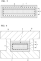
- Fig. 2 is a cross-sectional view showing the structure of a core prepared in the core preparation step (i).
- the core 3 comprises a fusible part 1 comprising a wax and an outer skin 2 covering the fusible part, and the fusible part 1 further comprises a first fusible part 1a comprising a first wax and a second fusible part 1b comprising a second wax.
- Melting points of the first wax and the second wax are different from each other, and the melting point of the first wax is lower than the melting point of the second wax.
- Both the melting point of the first wax and the melting point of the second wax are higher than room temperature (25°C) and are preferably 50°C or higher.
- the upper limit of the melting point that the first wax and the second wax should have will be described later.
- the first wax and the second wax are incompatible with each other. Therefore, a melt of the first wax does not dissolve the second wax, and when the melt of the first wax and a melt of the second wax are put into one container, the two are separated into two phases.
- the first fusible part 1a is disposed so as to be in contact with the outer skin 2, and this is advantageous in promoting fusion of the first fusible part 1a in the molding step (ii). As shown in Fig. 3 , this effect is conspicuous when a part of the fusible part 1 that is in contact with the outer skin 2 is entirely included in the first fusible part 1a.
- the fusible part 1 may consist of the first fusible part 1a.
- the first fusible part 1a may be divided into several parts.
- each of the first fusible parts 1a does not have to comprise a single piece.
- the first fusible part 1a may be configured by stacking two or more plates each comprising the first wax.
- the second fusible part 1b may comprise a single piece or may comprise a plurality of pieces.
- the first wax and the second wax are such that one is a wax comprising an organic compound having a polar group, while the other is a wax comprising a hydrocarbon as a main component. That is, when the first wax is a wax comprising an organic compound having a polar group, the second wax is a wax comprising a hydrocarbon as a main component, and when the first wax is a wax comprising a hydrocarbon as a main component, the second wax is a wax comprising an organic compound having a polar group.
- the polar group is a functional group including a carbon-oxygen bond or a carbon-nitrogen bond (except for an ether group), such as a hydroxyl group, an amino group, an amide group, a carbonyl group, a carboxyl group, or an ester group.
- a wax comprising a hydroxy fatty acid amide, a fatty acid amide, a hydroxy fatty acid ester, or a fatty acid ester as a main component is a typical example of the wax comprising an organic compound having a polar group.
- wax comprising a hydrocarbon as a main component examples include petroleum waxes such as paraffin wax and microcrystalline wax, as well as synthetic waxes such as Fischer-Tropsch wax, polyethylene wax, and polypropylene wax.
- additives can be added, if necessary, to the fusible part 1 of the core 3 shown in Fig. 2 to Fig. 4 .
- the additives may be added to both the first fusible part 1a and the second fusible part 1b or may be added to one of them only.
- the core 3 can be lightened by adding hollow particles having a particle specific gravity (specific gravity of individual particles) smaller than the specific gravity of the wax, to the fusible part 1.
- the core 3 may be made induction-heatable by adding particles of a material having a property of generating heat in a high-frequency electromagnetic field to the fusible part 1.
- a material having a property of generating heat in a high-frequency electromagnetic field examples include a ferromagnetic material, a ferrimagnetic material, and an electroconductive material.
- the ferromagnetic material include iron, nickel, cobalt, an iron alloy, a nickel alloy, a cobalt alloy, a permalloy, and many steels.
- the ferrimagnetic material include magnetite, nickel-zinc ferrite, manganese-zinc ferrite, and copper-zinc ferrite.
- the electroconductive material examples include copper, aluminum, and brass.
- the core 3 can be made microwave-heatable by adding particles of a material having a property of absorbing microwaves and thus generating heat, to the fusible part 1.
- a material having a property of absorbing microwaves and thus generating heat examples include silicon carbide, ferrite, barium titanate, anatase-type titanium oxide, graphite, and carbon black.
- All of the above-described particles may be hollow or may have a core-shell structure.
- Induction heating or microwave heating of the core can be performed in the molding step (ii) or can be performed when the core is preheated outside the mold before the molding step (ii).
- the material of the outer skin 2 should be capable of extensional deformation at the molding temperature.
- This extensional deformation may be elastic, may be plastic, or may have both natures.
- a preferred material for the outer skin 2 is, but not limited to, an organic material, and particularly a resin material.
- the preferred material for the outer skin 2 include synthetic polymers such as a polyolefin, a polyamide, a polyester, a polyurethane, a silicone, and a fluororubber, and further include elastomers comprising these polymers.
- a first wax piece prepared for the first fusible part 1a and a second wax piece prepared for the second fusible part 1b are wrapped with a polymer film prepared for the outer skin 2 and sealed by adhesion or fusion.
- the shapes of the first wax piece and the second wax piece are arranged such that as little space as possible is formed between the core to be produced and the prepreg preform to be produced in a subsequent step.
- the outer skin 2 can also be formed by using a shrink tube comprising the above-described polymer.
- a shrink tube in which a wax piece for the fusible part has been put in may be subjected to thermal shrinkage, and both ends of the shrink tube may be heat-sealed.
- the outer skin 2 can also be formed by using a low-temperature curable liquid rubber comprising the above-described polymer.
- a liquid rubber may be applied on a surface of a wax for the fusible part and cured at a temperature at which the wax does not fuse.
- a liquid rubber is applied on the surface of the wax for the fusible part, subsequently a nonwoven fabric made of a synthetic resin and capable of extensional deformation is stuck to the coated surface as a reinforcing material, the liquid rubber is further applied on the nonwoven fabric, and then the liquid rubber is cured.
- the outer skin 2 can also be formed of a UV-curable elastomer.
- a UV-curable elastomer is a UV-curable resin whose cured product is an elastic body such as rubber, and examples thereof include a UV-curable silicone rubber and a UV-curable urethane acrylate.
- the UV-curable elastomer is suitable as the material for the outer skin 2, from the viewpoint that the UV-curable elastomer can be cured in a short period of time even at room temperature.
- a prepreg preform 4 having a near net shape is prepared from one or two or more prepreg sheets, and disposed around the core 3 as shown in Fig. 5 .
- the prepreg preform 4 may be prepared so as to be in a state of enclosing the core 3 from the beginning, that is, in the state as shown in Fig. 5 .
- the prepreg preform 4 may be produced by combining different kinds of prepregs.
- the prepreg preform 4 can be produced by combining an SMC with one or more prepregs selected from a unidirectional prepreg, a cloth prepreg, and a tow prepreg.
- the prepreg preform 4 is disposed in a cavity of a mold 10 comprising a lower mold 12 and an upper mold 14, together with the core 3 enclosed by the prepreg preform 4, as shown in Fig. 6 .
- the mold 10 is heated to the same temperature as the molding temperature at this time.
- the mold 10 preferably has a vacuum mechanism.
- the temperature of the mold 10 is not limited to, but usually in a range from 120°C to 180°C, and preferably 140°C or higher. As the temperature of the mold 10 is higher, the time required for molding is shortened.
- the core 3 expands by absorbing heat transferred from the mold 10 through the prepreg preform 4, and the prepreg preform 4 is pressed against an inner surface of the mold 10. In other words, an internal pressure generated as the core 3 attempts to expand against the clamping force of the mold 10 is applied to the prepreg preform 4.
- the pressure applied to the prepreg preform 4 is weak, however, when the temperature near the surface of the core 3 reaches the melting point of the first wax, and the first fusible part 1a begins to fuse, the pressure applied to the prepreg preform 4 rises sharply. This is because when the wax fuses, its volume increases significantly.
- the fused first wax flows to spread evenly over the entire space between the unfused part of the fusible part 1 and the outer skin 12.
- the fused first wax acting as a pressure medium, all parts of the prepreg preform 4 are pressed against the inner surface of the mold 10 with substantially the same pressure.
- the first fusible part 1a is not required to fuse completely. Since the temperature of the first wax is maintained at its melting point until the first fusible part 1a fuses completely, fusion of the second fusible part 1b does not start.
- the melting point T m2 of the second wax is sufficiently higher than the melting point T m1 of the first wax, only the first fusible part 1a fuses in the molding step (ii). Therefore, a degree of expansion of the core 3 in the molding step (ii) can be controlled by regulating a volume ratio of the first fusible part 1a in the fusible part 1. This means, in other words, the pressure applied to the prepreg preform 4 by the expansion of the core 3 can be controlled.
- the melting point T m1 of the first wax constituting the first fusible part 1a is lower than the molding temperature T M , that is, the temperature of the mold 10 at the time of molding.
- the prepreg preform 4 When the prepreg preform 4 is too thick, since the transfer of heat from the mold 10 to the core 3 is delayed, irrespective of the fact that the melting point T m1 of the first wax is lower than the molding temperature T M , the prepreg preform 4 may begin to cure at a part in contact with the mold 10 before the first fusible part 1a fuses.
- an FRP cured in this stage has a bad appearance and may include voids.
- the prepreg preform 4 when the prepreg preform 4 is thick, it is desirable to lower the melting point T m1 of the first wax to make the first fusible part 1a fuse early.
- the melting point T m1 of the first wax is lower than 80°C.
- the prepreg preform 4 having a thickness of about 4 mm can be prevented from starting to cure before the first fusible part 1a fuses.
- unidirectional prepregs, cloth prepregs, tow prepregs, and the like have thicknesses of only about 0.2 mm, while it is common that even a single SMC has a thickness of about 2 mm. Therefore, the effect brought by lowering the melting point T m1 of the first wax is particularly prominent when the prepreg preform 4 comprises an SMC.
- the melting point T m2 of the second wax is equal to or higher than the molding temperature T M , fusion of the second wax during molding can be reliably prevented; however, on the other hand, the time required to fuse its entire amount in the wax removal step is lengthened.
- the melting point T m2 of the second wax is not necessarily required to be equal to or higher than the molding temperature T M .
- the difference between the melting point T m2 of the second wax and the molding temperature T M is not limited to, but preferably 40°C or less and may be 30°C or less, 25°C or less, or 20°C or less.
- the core 3 may be preheated before the molding step (ii).
- This preheating needs to be performed such that the temperature of the core 3 does not reach the melting point T m1 of the first wax. This is because when the first fusible part 1a is fused at the stage of preheating, it becomes impossible to pressurize the prepreg preform 4 utilizing large expansion of the core 3 concomitant to the fusion of the first fusible part 1a in the molding step (ii).
- the timing of preheating the core 3 is not limited, and the timing may be either before or after, or may be both before and after, disposing the prepreg preform 4 around the core 3.
- the prepreg preform 4 may be heated at the same time.
- a hot air circulation furnace can be preferably used for the preheating of the core 3, by using dielectric heating or microwave heating as additional means or alternative means, the preheating of the core 3 can be performed in a shorter period of time.
- particles of a material having a property of generating heat in a high-frequency electromagnetic field may be added to the fusible part 1 of the core 3 in advance.
- particles of a material having a property of absorbing microwaves and thus generating heat may be added to the fusible part 1 of the core 3 in advance.
- the prepreg preform 4 Since the prepreg preform 4 is prepared from a prepreg sheet, the prepreg preform 4 has at least any one of a butt joint between prepreg sheets 5 as shown in Fig. 7 and an overlap joint between prepreg sheets 5 as shown in Fig. 8 .
- the outer skin 2 of the core 3 has a role of sealing the gap between the prepreg sheets 5 at such a joint and preventing the fused wax from entering between the prepreg preform 4 and the mold 10. Therefore, the material of the outer skin 2 should be flexible and deformable at the molding temperature.
- the FRP product may be molded from two or more partial prepreg preforms.
- an FRP product 6 obtained thereby has a structure reinforced by a partition wall 8 located between two cavities 7, as shown in Fig. 10 .
- the partition wall 8 is cured in a sufficiently pressurized state and becomes void-free.
- a mold 10 having a cavity formed by a lower mold 12, an upper mold 14, and a slide core 16.
- the movement of the slide core 16 is controlled by a pressure control mechanism (not shown) using hydraulic pressure or the like, and even when the core 3 expands, the slide core 16 does not move until the pressure in the cavity reaches a predetermined value.
- the pressure in the cavity is about to exceed a predetermined value, the slide core 16 moves in the horizontal direction to relieve the pressure. It is convenient to control the molding pressure to be constant by using such a mold in order to stabilize the quality of the FRP product.
- the FRP product obtained by curing the prepreg preform 4 in the molding step (ii) is taken out from the mold 10, and the wax constituting the fusible part 1 is removed from the core 3 filling the cavity inside the FRP product.
- the outer skin 2 is not required to remove, when it is firmly fixed to the inner surface of the FRP product, and as long as it does not affect a function and an appearance of the FRP product.
- the wax constituting the fusible part 1 is fused by, for example, heating in an oven and is discharged through a drain hole that is formed in the FRP product using a drill or a hole saw. During heating, the temperature of the FRP product should not reach a thermal deformation temperature (deflection temperature under load).
- a through-hole H may be provided in the prepreg preform 4, and an FRP product may be molded with an elastomer plug 20 inserted into the through-hole H.
- the gap between the through-hole H and the elastomer plug 20 is closed by flow deformation of the prepreg during molding.
- a metal tube 30 is made to pierce through the elastomer plug 20, and as a result, a part or all of fused wax 8a and 8b in the cavity of the FRP product 6 is discharged through the metal tube 30 into a collection container 34 connected to the other end of the metal tube 30, as shown in Fig. 13 ,.
- the mold may be provided with an insertion hole for passing the metal tube, and before the upper mold is lifted, the metal tube may be pierced into the FRP product in the mold through this insertion hole to discharge a part or all of the wax.
- the timing of discharging the wax may be after the mold opening or may be before the mold opening.
- the reason why the elastomer plug 20 is tapered along the direction of insertion into the through-hole H is to prevent the elastomer plug 20 from coming off due to the pressure inside the cavity after the molding and before the discharging of the wax, and accordingly, the elastomer plug 20 is inserted into the through-hole H such that the side having a larger diameter of the cross-section orthogonal to the direction of insertion faces toward the core 3.
- protrusions or dents may be provided on the side surface of the elastomer plug.
- a material of the elastomer plug is not limited to, but can be an acrylic rubber, a fluororubber, a silicone rubber, a nitrile rubber, and a butyl rubber.
- the tip of the metal tube may be sharpened so that it can easily pierce the elastomer plug.
- the melting point T m2 of the second wax is lower by 20°C or more than the thermal deformation temperature of the FRP product, so that the second wax can be rapidly removed from the FRP product.
- first wax and the second wax are incompatible with each other, they can be easily separated and reused.
- the difference in the melting point can be utilized to fuse only the first wax for separating it from the second wax.
- the first wax and the second wax can be separated utilizing the difference in the specific gravity.
- the FRP product manufacturing method according to the embodiment has been described above using the case of manufacturing a hollow cuboid FRP article as an example, however, an external shape of the FRP product that can be manufactured by this manufacturing method is not limited to a cuboid.
- This manufacturing method can be applied to the manufacture of various FRP products having a structure including a bent or curved wall surface.
- the FRP product manufacturing method according to the embodiment can be used not only for manufacturing a structure comprising only an FRP, but also for manufacturing a structure in which an FRP is integrally molded with a metal component, and manufacturing a structure in which an FRP comprising a thermosetting resin and an FRP comprising a thermoplastic resin are integrally molded.
- Another embodiment of the present invention relates to a core used for manufacturing an FRP product.
- the core of the embodiment is a core that can be disposed in a mold together with a prepreg when an FRP product having a structure including a bent or curved wall surface is manufactured by curing the prepreg by heating and pressurizing in the mold.
- This core comprises a fusible part comprising a wax and an outer skin covering the fusible part.
- the fusible part may have a part comprising a wax having a melting point of lower than 80°C, and this part is preferably in contact with the outer skin.
- the fusible part may consist of a part comprising a wax having a melting point of lower than 80°C.
- the fusible part may also have, in addition to the part comprising a wax having a melting point of lower than 80°C, another part comprising another wax that has a melting point higher than that of the wax and is incompatible with the wax.
- the wax having a melting point of lower than 80°C and the other wax may be such that one of them is a wax comprising an organic compound having a polar group while the other one is a wax including a hydrocarbon as a main component.
- particles of a material having a property of generating heat in a high-frequency electromagnetic field may be added to the fusible part.
- particles of a material having a property of absorbing microwaves and thus generating heat may be added to the fusible part.
- the core according to the embodiment can be preferably used in the manufacturing method for an FRP product described in the above-described section 1.
- the cores exemplified in the description of the FRP product manufacturing method in the above-described section 1. are all examples of the cores according to the embodiment.
- a hollow cuboid comprising an FRP and having a size of 100 mm ⁇ 50 mm ⁇ 22 mm was experimentally produced by the following procedure.
- the core had a fusible part which comprised a synthetic wax (ITOWAX E-210 manufactured by Itoh Oil Chemicals Co., Ltd.) comprising methyl 12-hydroxystearate and having a melting point of 50°C and was covered with an outer skin formed by using a shrink tube made of a polyolefin and having a thickness of 15 ⁇ m.
- the core was produced to be a cuboid having a size that just fitted into the prepreg preform.
- the prepreg preform was placed, together with the core enclosed by the prepreg preform, in a mold that had been heated in advance to the same temperature as a molding temperature, and the prepreg preform was heated and pressurized to be cured.
- the molding temperature was set to 140°C, and a molding time was set to 15 minutes.
- the molding time is a time from mold clamping to mold opening.
- a hole having a diameter of 10 mm was drilled in the molded article taken out from the mold, and all the wax inside the molded article was fused by heating to 130°C and then discharged through this hole.
- the appearance of the obtained hollow cuboid was favorable, and neither corner chippings nor wrinkles on a wall surface were observed.
- a hollow cuboid comprising an FRP was experimentally produced in the same manner as in Experiment 1, except that the fusible part of the core was formed with a synthetic wax (ITOWAX E-70G manufactured by Itoh Oil Chemicals Co., Ltd.) comprising a higher fatty acid ester and having a melting point of 68°C, instead of the synthetic wax comprising methyl 12-hydroxystearate and having a melting point of 50°C.
- a synthetic wax IOWAX E-70G manufactured by Itoh Oil Chemicals Co., Ltd.
- the appearance of the obtained hollow cuboid was favorable, and neither corner chippings nor wrinkles on a wall surface were observed.
- a hollow cuboid comprising an FRP was experimentally produced in the same manner as in Experiment 1, except that the fusible part of the core was not formed with one kind of wax but was formed with the synthetic wax (ITOWAX E-70G manufactured by Itoh Oil Chemicals Co., Ltd.) having a melting point of 68°C used for the core in Experiment 2 and a polyethylene wax (File-A-Wax Green manufactured by Freeman Manufacturing & Supply Company) having a melting point of 117°C and being incompatible with the above-described synthetic wax.
- the synthetic wax IOWAX E-70G manufactured by Itoh Oil Chemicals Co., Ltd.
- File-A-Wax Green manufactured by Freeman Manufacturing & Supply Company
- the core using the two kinds of waxes was configured by disposing pieces of the synthetic wax having a melting point of 68°C around pieces of the polyethylene wax having a melting point of 117°C. That is, wax pieces having a lower melting point were disposed at a part in contact with the outer skin.
- a volume ratio of the amounts of the two kinds of waxes used was 1: 1.
- the appearance of the obtained hollow cuboid was favorable, and neither corner chippings nor wrinkles on a wall surface were observed.
- a hollow cuboid comprising an FRP was experimentally produced in the same manner as in Experiment 1, except that the fusible part of the core was formed with the polyethylene wax (File-A-Wax Green manufactured by Freeman Manufacturing & Supply Company) having a melting point of 117°C, instead of the synthetic wax comprising methyl 12-hydroxystearate and having a melting point of 50°C.
- the polyethylene wax File-A-Wax Green manufactured by Freeman Manufacturing & Supply Company
- the obtained hollow cuboid had inferior appearance as compared with the ones obtained in the above-described Experiments 1 to 3, and had some corner chippings as well as wrinkles observed on a part of the wall surface.
- a hollow cuboid comprising an FRP and having a size of 72 mm ⁇ 36 mm ⁇ 20 mm was experimentally produced by the following procedure.
- One sheet of an SMC (STR120N131 manufactured by Mitsubishi Chemical Corporation) having a thickness of 2 mm was cut into a predetermined shape, while forming, in a part thereof, a cylindrical through-hole with an inner diameter of 6 mm, and folded to prepare a prepreg preform having a near net shape.
- the core had a fusible part which comprises the synthetic wax (ITOWAX E-70G manufactured by Itoh Oil Chemicals Co., Ltd.) comprising a higher fatty acid ester and having a melting point of 68°C covered with an outer skin formed by using a nylon 6 film having a thickness of 7 ⁇ m.
- the core was produced to be a cuboid having a size that just fitted into the prepreg preform.
- a silicone rubber plug was inserted into the through-hole provided in the SMC.
- This silicone rubber plug was a frustoconical tapered plug having a diameter of 6 mm at the upper surface, a diameter of 10 mm at the lower surface, and a height of 4 mm and was inserted into the through-hole such that the lower surface faced the core.
- the prepreg preform was placed, together with the core enclosed by the prepreg preform, in a mold that had been heated to the same temperature as the molding temperature in advance such that the surface provided with the through-hole faced upward, and the prepreg preform was heated and pressurized to be cured.
- the molding temperature was set to 140°C, and the molding time was set to 10 minutes.
- one end of a stainless steel tube having an outer diameter of 2 mm and an inner diameter of 1 mm was made to pierce through the silicone rubber plug, resulting in that the fused wax flowed from the inside of the molded article through the stainless steel tube into a container connected to the other end of the stainless steel tube.
- the invention disclosed in the present specification can be preferably used in the manufacture of an FRP product having a structure including a bent or curved wall surface.
- the invention disclosed herein can be preferably used, without any limitations, when components (including structural components) for automobiles, ships, railway vehicles, aircraft and other transportation equipment, as well as various sports goods including bicycle frames, tennis rackets, and golf shafts are manufactured with fiber reinforced plastics.
Landscapes
- Mechanical Engineering (AREA)
- Engineering & Computer Science (AREA)
- Physics & Mathematics (AREA)
- Health & Medical Sciences (AREA)
- Composite Materials (AREA)
- Chemical & Material Sciences (AREA)
- Oral & Maxillofacial Surgery (AREA)
- Thermal Sciences (AREA)
- Electromagnetism (AREA)
- Toxicology (AREA)
- Casting Or Compression Moulding Of Plastics Or The Like (AREA)
- Moulding By Coating Moulds (AREA)
- Moulds For Moulding Plastics Or The Like (AREA)
Abstract
Description
- The present invention mainly relates to a manufacturing method for a fiber reinforced plastic product and a core used for manufacturing a fiber reinforced plastic product.
- Priority is claimed on
Japanese Patent Application No. 2020-056726, filed March 26, 2020 - Fiber reinforced plastic (FRP) products are used in various use applications including a reinforcement for automobiles.
- As a method for molding an FRP product having a hollow part or a U-shaped cross-section part, a method including disposing a prepreg preform in a mold together with a core comprising a wax and curing it while pressurizing by causing the core to expand inside the mold has been proposed (Patent Document 1).
- [Patent Document 1]
PCT International Publication No. WO 2018/079824 - Amain object of the present invention is to provide beneficial improvements relating to a manufacturing method for a fiber reinforced plastic product, the manufacturing method including curing while pressurizing a prepreg preform by using a core comprising a wax.
- The problems solved by each embodiment of the present invention may be disclosed explicitly or implicitly in the specification.
- Embodiments of the present invention include the following, but are not limited thereto.
- [1] A manufacturing method for a fiber reinforced plastic product, including: a molding step including disposing a prepreg preform in a mold together with a core comprising a fusible part comprising a wax and an outer skin covering the fusible part, and heating and pressurizing the prepreg preform in the mold to obtain a cured product, and in which the prepreg preform is at least partially pressurized by expansion of the core; and a wax removal step including removing the wax from the cured product, wherein a molding temperature in the molding step is 140°C or higher, the prepreg preform at least partially has a thickness of 1 mm or more, and the fusible part has a first fusible part comprising a first wax having a melting point of lower than 80°C.
- [2] The manufacturing method according to [1], wherein the first fusible part is in contact with the outer skin.
- [3] The manufacturing method according to [1] or [2], wherein the core is preheated before the molding step.
- [4] The manufacturing method according to [3], wherein the fusible part comprises particles of a material having a property of generating heat in a high-frequency electromagnetic field, and the preheating is performed by induction heating.
- [5] The manufacturing method according to [3], wherein the fusible part comprises particles of a material having a property of absorbing microwaves and thus generating heat, and the preheating is performed by microwave heating.
- [6] The manufacturing method according to any one of [1] to [5], wherein the fusible part consists of the first fusible part.
- [7] The manufacturing method according to any one of [1] to [5], wherein the fusible part comprises the first fusible part and a second fusible part comprising a second wax having a melting point higher than that of the first wax and being incompatible with the first wax.
- [8] The manufacturing method according to [7], wherein one of the first wax and the second wax is a wax comprising an organic compound having a polar group, and the other is a wax comprising a hydrocarbon as a main component.
- [9] The manufacturing method according to any one of [1] to [8], wherein the prepreg preform comprises an SMC.
- [10] The manufacturing method according to any one of [1] to [9], wherein in the molding step, a plurality of the prepreg preforms are disposed in the mold such that each of the prepreg preforms encloses one said core, and the prepreg preforms are heated and pressurized in the mold to obtain a single cured product.
- [11] The manufacturing method according to any one of [1] to [10], wherein the mold comprises a cavity formed by a lower mold, an upper mold, and a slide core.
- [12] A core to be disposed in a mold together with a prepreg when a fiber reinforced plastic product is manufactured by curing the prepreg by heating and pressurizing thereof in the mold, the core comprising a fusible part comprising a wax and an outer skin covering the fusible part, wherein the fusible part has a first fusible part comprising a first wax having a melting point of lower than 80°C.
- [13] The core according to [12], wherein the first fusible part is in contact with the outer skin.
- [14] The core according to [12] or [13], wherein the fusible part comprises particles of a material having a property of generating heat in a high-frequency electromagnetic field.
- [15] The core according to [12] or [13], wherein the fusible part comprises particles of a material having a property of absorbing microwaves and thus generating heat.
- [16] The core according to any one of [12] to [15], wherein the fusible part consists of the first fusible part.
- [17] The core according to any one of [12] to [15], wherein the fusible part comprises the first fusible part and a second fusible part comprising a second wax having a melting point higher than that of the first wax and being incompatible with the first wax.
- [18] The core according to [17], wherein one of the first wax and the second wax is a wax comprising an organic compound having a polar group, and the other is a wax comprising a hydrocarbon as a main component.
- [19] A core to be disposed in a mold together with a prepreg when a fiber reinforced plastic product is manufactured by curing the prepreg by heating and pressurizing thereof in the mold, the core comprising a fusible part comprising a wax and an outer skin covering the fusible part, wherein the fusible part comprises particles of a material having a property of generating heat in a high-frequency electromagnetic field.
- [20] The core according to [19], wherein the fusible part comprises a first fusible part comprising a first wax and a second fusible part comprising a second wax having a melting point higher than that of the first wax and being incompatible with the first wax.
- [21] The core according to [20], wherein the first fusible part is in contact with the outer skin.
- [22] The core according to [20] or [21], wherein one of the first wax and the second wax is a wax comprising an organic compound having a polar group, and the other is a wax comprising a hydrocarbon as a main component.
- [23] A manufacturing method for a fiber reinforced plastic product, including: a molding step including disposing a prepreg in a mold together with the core according to any one of [19] to [22] and heating and pressurizing the prepreg in the mold to obtain a cured product; and a wax removal step including removing the wax constituting the fusible part of the core from the cured product, wherein the core is preheated by induction heating before the molding step, and in the molding step, the fusible part of the core at least partially fuses, and the prepreg is at least partially pressurized by expansion of the core.
- [24] A core to be disposed in a mold together with a prepreg when a fiber reinforced plastic product is manufactured by curing the prepreg by heating and pressurizing thereof in the mold, the core comprising a fusible part comprising a wax and an outer skin covering the fusible part, wherein the fusible part comprises particles of a material having a property of absorbing microwaves and thus generating heat.
- [25] The core according to [24], wherein the fusible part comprises a first fusible part comprising a first wax and a second fusible part comprising a second wax having a melting point higher than that of the first wax and being incompatible with the first wax.
- [26] The core according to [25], wherein the first fusible part is in contact with the outer skin.
- [27] The core according to [25] or [26], wherein one of the first wax and the second wax is a wax comprising an organic compound having a polar group, and the other is a wax comprising a hydrocarbon as a main component.
- [28] A manufacturing method for a fiber reinforced plastic product, including: a molding step including disposing a prepreg in a mold together with the core according to any one of [24] to [27] and heating and pressurizing the prepreg in the mold to obtain a cured product; and a wax removal step including removing the wax constituting the fusible part of the core from the cured product, wherein the core is preheated by microwave heating before the molding step, and in the molding step, the fusible part of the core at least partially fuses, and the prepreg is at least partially pressurized by expansion of the core.
- [29] A manufacturing method for a fiber reinforced plastic product, including disposing a prepreg in a mold together with the core according to any one of [12] to [22] and [24] to [27] and curing the prepreg by heating and pressurizing thereof in the mold.
- [30] Use of the core according to any one of [12] to [22] and [24] to [27], in a manufacturing method for a fiber reinforced plastic product including disposing a prepreg in a mold together with a core and curing the prepreg by heating and pressurizing thereof in the mold.
- [31] A manufacturing method for a fiber reinforced plastic product, including: a molding step including heating and pressurizing a prepreg preform in a mold to obtain a cured product having a hollow part, the prepreg preform having a core-containing part in which a core comprising a fusible part comprising a wax and an outer skin covering the fusible part, is wrapped with a prepreg sheet; and a wax removal step including removing the wax from an inside of the hollow part, wherein the prepreg preform has a through-hole formed in the core-containing part, and an elastomer plug is inserted into the through-hole.
- [32] The manufacturing method according to [31], wherein the elastomer plug is at least partially tapered along a direction of insertion into the through-hole.
- [33] The manufacturing method according to [32], wherein the elastomer plug is inserted into the through-hole such that a side having a larger diameter of a cross-section orthogonal to the direction of insertion into the through-hole faces toward the core.
- [34] The manufacturing method according to any one of [31] to [33], wherein the elastomer plug has a protrusion or a dent on a side surface.
- [35] The manufacturing method according to any one of [31] to [34], wherein in the wax removal step, one end of a metal tube is made to pierce through the elastomer plug, and all or a part of the wax is discharged from the hollow part through the metal tube.
- [36] The manufacturing method according to [35], wherein in the wax removal step, the metal tube is at least partially heated.
- [37] The manufacturing method according to [35] or [36], wherein the other end of the metal tube is connected to a collection container.
- [38] The manufacturing method according to any one of [31] to [37], wherein the core is preheated before the molding step.
- [39] The manufacturing method according to [38], wherein the fusible part comprises particles of a material having a property of generating heat in a high-frequency electromagnetic field, and the preheating is performed by induction heating.
- [40] The manufacturing method according to [38], wherein the fusible part comprises particles of a material having a property of absorbing microwaves and thus generating heat, and the preheating is performed by microwave heating.
- [41] The manufacturing method according to any one of [31] to [40], wherein the prepreg preform at least partially has a thickness of 1 mm or more in the core-containing part, the fusible part has a first fusible part comprising a first wax having a melting point of lower than 80°C, and the molding temperature in the molding step is 140°C or higher.
- [42] The manufacturing method according to [41], wherein the first fusible part is in contact with the outer skin.
- [43] The manufacturing method according to [41] or [42], wherein the fusible part consists of the first fusible part.
- [44] The manufacturing method according to [41] or [42], wherein the fusible part comprises the first fusible part and a second fusible part comprising a second wax having a melting point higher than that of the first wax and being incompatible with the first wax.
- [45] The manufacturing method according to [44], wherein one of the first wax and the second wax is a wax comprising an organic compound having a polar group, and the other is a wax comprising a hydrocarbon as a main component.
- [46] The manufacturing method according to any one of [41] to [45], wherein the prepreg preform comprises an SMC.
- [47] A manufacturing method for a fiber reinforced plastic product, including: a molding step including disposing a prepreg preform in a mold together with a core comprising a fusible part comprising a wax and an outer skin covering the fusible part, and heating and pressurizing the prepreg preform in the mold to obtain a cured product, and in which the prepreg preform is at least partially pressurized by expansion of the core; and a wax removal step including removing the wax from the cured product, wherein the core is preheated before the molding step.
- [48] The manufacturing method according to [47], wherein the fusible part has a first fusible part comprising a first wax having a melting point of lower than 80°C.
- [49] The manufacturing method according to [48], wherein the first fusible part is in contact with the outer skin.
- [50] The manufacturing method according to [48] or [49], wherein the fusible part consists of the first fusible part.
- [51] The manufacturing method according to [48] or [49], wherein the fusible part comprises the first fusible part and a second fusible part comprising a second wax having a melting point higher than that of the first wax and being incompatible with the first wax.
- [52] The manufacturing method according to [51], wherein one of the first wax and the second wax is a wax comprising an organic compound having a polar group, and the other is a wax comprising a hydrocarbon as a main component.
- [53] The manufacturing method according to any one of [47] to [52], wherein the prepreg preform at least partially has a thickness of 1 mm or more.
- [54] The manufacturing method according to [53], wherein the prepreg preform comprises an SMC.
- [55] The manufacturing method according to any one of [47] to [54], wherein the molding temperature in the molding step is 140°C or higher.
- There are provided beneficial improvements relating to a manufacturing method for a fiber reinforced plastic product, the manufacturing method including curing while pressurizing a prepreg preform by using a core comprising a wax.
-
-
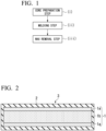
Fig. 1 is a flow chart for an FRP product manufacturing method according to an embodiment. -
Fig. 2 is a cross-sectional view showing a structure of a core that can be used in the FRP product manufacturing method according to the embodiment. -
Fig. 3 is a cross-sectional view showing the structure of a core that can be used in the FRP product manufacturing method according to the embodiment. -
Fig. 4 is a cross-sectional view showing the structure of a core that can be used in the FRP product manufacturing method according to the embodiment. -
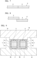
Fig. 5 is a cross-sectional view showing that a prepreg preform having a near net shape is disposed around a core. -
Fig. 6 is a cross-sectional view showing that a prepreg preform is disposed in a cavity of a mold together with a core enclosed by the prepreg preform. -
Fig. 7 is a cross-sectional view showing a butt part between prepreg sheet edges. -
Fig. 8 is a cross-sectional view showing an overlap joint between prepreg sheet edges. -
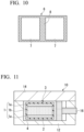
Fig. 9 is a cross-sectional view showing two partial prepreg preforms disposed in a mold cavity each together with a core enclosed by the prepreg preform. -
Fig. 10 is a cross-sectional view showing an FRP article molded from the two partial prepreg preforms shown inFig. 9 . -
Fig. 11 is a cross-sectional view showing a prepreg preform disposed in a mold cavity together with a core enclosed by the prepreg preform. -
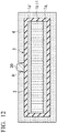
Fig. 12 is a cross-sectional view showing that a prepreg preform having a near net shape is disposed around a core. -
Fig. 13 shows that one end of a metal tube is made to pierce through the elastomer plug to discharge a wax in the cavity of an FRP product into a collection container through the metal tube. - A prepreg (pre-impregnated composite material) is a composite comprising fibers and a thermosetting resin, the composite being used as an intermediate material in the manufacture of FRP products. An FRP product is manufactured by preforming a prepreg and then curing it in a mold.
- The form of fibers in the prepreg varies from long fibers to a woven fabric, a nonwoven fabric, a non-crimp fabric, short fibers, and the like. A sheet type prepreg obtained by impregnating a long fiber bundle aligned in one direction in one plane with a resin is called a unidirectional prepreg (UD prepreg). A prepreg obtained by impregnating a woven fabric woven with long fiber bundles, with a resin is called a cloth prepreg. A prepreg obtained by impregnating a mat comprising chopped short fiber bundles with a resin is called an SMC (sheet molding compound). A prepreg obtained by impregnating a single long fiber bundle with a resin is called a tow prepreg.
- Examples of the fibers used for a prepreg include carbon fibers, glass fibers, aramid fibers, silicon carbide fibers, and metal fibers. Two or more kinds of fibers may be used in combination.
- Examples of the thermosetting resin used for a prepreg include an epoxy resin, a urea resin, a vinyl ester resin (also called an epoxy acrylate resin), an unsaturated polyester resin, a polyurethane resin, and a phenol resin. A mixture of two or more kinds of thermosetting resins may also be used.
- A content of the thermosetting resin in the prepreg is not limited to, but in many cases 15% to 50% by mass. The content may be 15% to 20% by mass, 20% to 25% by mass, 25% to 40% by mass, 40% to 45% by mass, or 45% to 50% by mass.
- Various additives can be added to a prepreg. Examples include a reactive diluent, a low shrinkage agent, a flame retardant, an antifoaming agent, a defoaming agent, a mold release agent, a particulate filler, a colorant, and a silane coupling agent.
- One of the embodiments of the present invention relates to a manufacturing method for an FRP product.
- In the following description, the FRP product manufacturing method according to the embodiment will be divided into the following three steps as shown in the flow chart of
Fig. 1 , for the convenience of explanation. - (i) A core preparation step including preparing a core comprising a fusible part comprising a wax and an outer skin covering the fusible part.
- (ii) A molding step including disposing a prepreg preform in a mold together with the core and heating and pressurizing the prepreg preform in the mold to obtain a cured product (FRP product).
- (iii) A wax removal step including removing the wax from the cured product.
- The FRP product manufacturing method according to the embodiment is preferably used for manufacturing an FRP product having a structure including a bent or curved wall surface. Typical examples of the structure including a bent or curved wall surface include a hollow structure, a cylindrical structure, a structure with a U-shaped cross-section, and a structure with an L-shaped cross-section. Various undercuts also often include bent or curved wall surfaces in the structure.
- Hereinafter, each of the steps (i) to (iii) will be described in detail with reference to the drawings, by taking a case where a hollow cuboid article is manufactured as an FRP product, as an example. The hollow cuboid has a wall surface bent at an angle of 90 degrees.
-
Fig. 2 is a cross-sectional view showing the structure of a core prepared in the core preparation step (i). - The
core 3 comprises afusible part 1 comprising a wax and anouter skin 2 covering the fusible part, and thefusible part 1 further comprises a firstfusible part 1a comprising a first wax and a secondfusible part 1b comprising a second wax. - Melting points of the first wax and the second wax are different from each other, and the melting point of the first wax is lower than the melting point of the second wax.
- Both the melting point of the first wax and the melting point of the second wax are higher than room temperature (25°C) and are preferably 50°C or higher. The upper limit of the melting point that the first wax and the second wax should have will be described later.
- The first wax and the second wax are incompatible with each other. Therefore, a melt of the first wax does not dissolve the second wax, and when the melt of the first wax and a melt of the second wax are put into one container, the two are separated into two phases.
- The first
fusible part 1a is disposed so as to be in contact with theouter skin 2, and this is advantageous in promoting fusion of the firstfusible part 1a in the molding step (ii). As shown inFig. 3 , this effect is conspicuous when a part of thefusible part 1 that is in contact with theouter skin 2 is entirely included in the firstfusible part 1a. - In an example, as shown in
Fig. 4 , thefusible part 1 may consist of the firstfusible part 1a. - As can be seen from
Fig. 2 , the firstfusible part 1a may be divided into several parts. - In any of the examples shown in
Fig. 2 to Fig. 4 , each of the firstfusible parts 1a does not have to comprise a single piece. For example, inFig. 4 , the firstfusible part 1a may be configured by stacking two or more plates each comprising the first wax. - The same also applies to the second
fusible part 1b, and the secondfusible part 1b may comprise a single piece or may comprise a plurality of pieces. - According to the investigation made by the present inventors, there is a tendency that a wax comprising an organic compound having a polar group and a wax comprising a hydrocarbon as a main component are less likely to be compatible with each other. Therefore, in a suitable example, the first wax and the second wax are such that one is a wax comprising an organic compound having a polar group, while the other is a wax comprising a hydrocarbon as a main component. That is, when the first wax is a wax comprising an organic compound having a polar group, the second wax is a wax comprising a hydrocarbon as a main component, and when the first wax is a wax comprising a hydrocarbon as a main component, the second wax is a wax comprising an organic compound having a polar group.
- The polar group is a functional group including a carbon-oxygen bond or a carbon-nitrogen bond (except for an ether group), such as a hydroxyl group, an amino group, an amide group, a carbonyl group, a carboxyl group, or an ester group. A wax comprising a hydroxy fatty acid amide, a fatty acid amide, a hydroxy fatty acid ester, or a fatty acid ester as a main component is a typical example of the wax comprising an organic compound having a polar group.
- Examples of the wax comprising a hydrocarbon as a main component include petroleum waxes such as paraffin wax and microcrystalline wax, as well as synthetic waxes such as Fischer-Tropsch wax, polyethylene wax, and polypropylene wax.
- Various additives can be added, if necessary, to the
fusible part 1 of thecore 3 shown inFig. 2 to Fig. 4 . The additives may be added to both the firstfusible part 1a and the secondfusible part 1b or may be added to one of them only. - In an example, the
core 3 can be lightened by adding hollow particles having a particle specific gravity (specific gravity of individual particles) smaller than the specific gravity of the wax, to thefusible part 1. - In another example, the
core 3 may be made induction-heatable by adding particles of a material having a property of generating heat in a high-frequency electromagnetic field to thefusible part 1. Examples of such a material include a ferromagnetic material, a ferrimagnetic material, and an electroconductive material. Examples of the ferromagnetic material include iron, nickel, cobalt, an iron alloy, a nickel alloy, a cobalt alloy, a permalloy, and many steels. Examples of the ferrimagnetic material include magnetite, nickel-zinc ferrite, manganese-zinc ferrite, and copper-zinc ferrite. Examples of the electroconductive material include copper, aluminum, and brass. - In still another example, the
core 3 can be made microwave-heatable by adding particles of a material having a property of absorbing microwaves and thus generating heat, to thefusible part 1. Examples of such a material include silicon carbide, ferrite, barium titanate, anatase-type titanium oxide, graphite, and carbon black. - All of the above-described particles may be hollow or may have a core-shell structure.
- Induction heating or microwave heating of the core can be performed in the molding step (ii) or can be performed when the core is preheated outside the mold before the molding step (ii).
- In order to prevent the
outer skin 2 from being broken by the deformation and expansion of thefusible part 1 in the molding step (ii), the material of theouter skin 2 should be capable of extensional deformation at the molding temperature. This extensional deformation may be elastic, may be plastic, or may have both natures. - Therefore, a preferred material for the
outer skin 2 is, but not limited to, an organic material, and particularly a resin material. Examples of the preferred material for theouter skin 2 include synthetic polymers such as a polyolefin, a polyamide, a polyester, a polyurethane, a silicone, and a fluororubber, and further include elastomers comprising these polymers. - When manufacturing the
core 3, for example, a first wax piece prepared for the firstfusible part 1a and a second wax piece prepared for the secondfusible part 1b are wrapped with a polymer film prepared for theouter skin 2 and sealed by adhesion or fusion. The shapes of the first wax piece and the second wax piece are arranged such that as little space as possible is formed between the core to be produced and the prepreg preform to be produced in a subsequent step. - The
outer skin 2 can also be formed by using a shrink tube comprising the above-described polymer. A shrink tube in which a wax piece for the fusible part has been put in may be subjected to thermal shrinkage, and both ends of the shrink tube may be heat-sealed. - The
outer skin 2 can also be formed by using a low-temperature curable liquid rubber comprising the above-described polymer. A liquid rubber may be applied on a surface of a wax for the fusible part and cured at a temperature at which the wax does not fuse. In a modified method, it is also acceptable that a liquid rubber is applied on the surface of the wax for the fusible part, subsequently a nonwoven fabric made of a synthetic resin and capable of extensional deformation is stuck to the coated surface as a reinforcing material, the liquid rubber is further applied on the nonwoven fabric, and then the liquid rubber is cured. - The
outer skin 2 can also be formed of a UV-curable elastomer. A UV-curable elastomer is a UV-curable resin whose cured product is an elastic body such as rubber, and examples thereof include a UV-curable silicone rubber and a UV-curable urethane acrylate. The UV-curable elastomer is suitable as the material for theouter skin 2, from the viewpoint that the UV-curable elastomer can be cured in a short period of time even at room temperature. - In the molding step (ii), first, a
prepreg preform 4 having a near net shape is prepared from one or two or more prepreg sheets, and disposed around thecore 3 as shown inFig. 5 . In an example, rather than preparing theprepreg preform 4 in a separate step and then combining it with thecore 3, theprepreg preform 4 may be prepared so as to be in a state of enclosing thecore 3 from the beginning, that is, in the state as shown inFig. 5 . - The
prepreg preform 4 may be produced by combining different kinds of prepregs. In a preferred example, theprepreg preform 4 can be produced by combining an SMC with one or more prepregs selected from a unidirectional prepreg, a cloth prepreg, and a tow prepreg. - After preparing the
prepreg preform 4, theprepreg preform 4 is disposed in a cavity of amold 10 comprising alower mold 12 and anupper mold 14, together with thecore 3 enclosed by theprepreg preform 4, as shown inFig. 6 . Usually, themold 10 is heated to the same temperature as the molding temperature at this time. Themold 10 preferably has a vacuum mechanism. - Next, the
mold 10 is clamped to cure theprepreg preform 4. The temperature of themold 10 is not limited to, but usually in a range from 120°C to 180°C, and preferably 140°C or higher. As the temperature of themold 10 is higher, the time required for molding is shortened. - The
core 3 expands by absorbing heat transferred from themold 10 through theprepreg preform 4, and theprepreg preform 4 is pressed against an inner surface of themold 10. In other words, an internal pressure generated as thecore 3 attempts to expand against the clamping force of themold 10 is applied to theprepreg preform 4. - Immediately after the mold clamping, since a volume of the
core 3 increases only gradually due to thermal expansion, the pressure applied to theprepreg preform 4 is weak, however, when the temperature near the surface of thecore 3 reaches the melting point of the first wax, and the firstfusible part 1a begins to fuse, the pressure applied to theprepreg preform 4 rises sharply. This is because when the wax fuses, its volume increases significantly. - The fused first wax flows to spread evenly over the entire space between the unfused part of the
fusible part 1 and theouter skin 12. By the fused first wax acting as a pressure medium, all parts of theprepreg preform 4 are pressed against the inner surface of themold 10 with substantially the same pressure. - In the molding step (ii), the first
fusible part 1a is not required to fuse completely. Since the temperature of the first wax is maintained at its melting point until the firstfusible part 1a fuses completely, fusion of the secondfusible part 1b does not start. When the melting point Tm2 of the second wax is sufficiently higher than the melting point Tm1 of the first wax, only the firstfusible part 1a fuses in the molding step (ii). Therefore, a degree of expansion of thecore 3 in the molding step (ii) can be controlled by regulating a volume ratio of the firstfusible part 1a in thefusible part 1. This means, in other words, the pressure applied to theprepreg preform 4 by the expansion of thecore 3 can be controlled. - In order to pressurize the
prepreg preform 4 by utilizing the large expansion of thecore 3 concomitant to the fusion of thefusible part 1, it is necessary that the melting point Tm1 of the first wax constituting the firstfusible part 1a is lower than the molding temperature TM, that is, the temperature of themold 10 at the time of molding. - However, when the
prepreg preform 4 is thick, that alone may be insufficient. - When the
prepreg preform 4 is too thick, since the transfer of heat from themold 10 to thecore 3 is delayed, irrespective of the fact that the melting point Tm1 of the first wax is lower than the molding temperature TM, theprepreg preform 4 may begin to cure at a part in contact with themold 10 before the firstfusible part 1a fuses. - Until the first
fusible part 1a fuses, thecore 3 only weakly presses theprepreg preform 4 against the inner surface of themold 10, thus an FRP cured in this stage has a bad appearance and may include voids. - Accordingly, when the
prepreg preform 4 is thick, it is desirable to lower the melting point Tm1 of the first wax to make the firstfusible part 1a fuse early. - Specifically, when the thickness of the
prepreg preform 4 is at least partially 1 mm or more, it is preferable that the melting point Tm1 of the first wax is lower than 80°C. For example, when the melting point Tm1 of the first wax is lower than 70°C, theprepreg preform 4 having a thickness of about 4 mm can be prevented from starting to cure before the firstfusible part 1a fuses. - Among the prepregs, unidirectional prepregs, cloth prepregs, tow prepregs, and the like have thicknesses of only about 0.2 mm, while it is common that even a single SMC has a thickness of about 2 mm. Therefore, the effect brought by lowering the melting point Tm1 of the first wax is particularly prominent when the
prepreg preform 4 comprises an SMC. - When the melting point Tm2 of the second wax is equal to or higher than the molding temperature TM, fusion of the second wax during molding can be reliably prevented; however, on the other hand, the time required to fuse its entire amount in the wax removal step is lengthened. Depending on the molding temperature and the molding time, the melting point Tm2 of the second wax is not necessarily required to be equal to or higher than the molding temperature TM. When the melting point Tm2 of the second wax is lower than the molding temperature TM, the difference between the melting point Tm2 of the second wax and the molding temperature TM is not limited to, but preferably 40°C or less and may be 30°C or less, 25°C or less, or 20°C or less.
- In an example, in order for the first
fusible part 1a to fuse sufficiently early, in addition to lowering the melting point Tm1 of the first wax, or in place of lowering the melting point Tm1 of the first wax, thecore 3 may be preheated before the molding step (ii). - This preheating needs to be performed such that the temperature of the
core 3 does not reach the melting point Tm1 of the first wax. This is because when the firstfusible part 1a is fused at the stage of preheating, it becomes impossible to pressurize theprepreg preform 4 utilizing large expansion of thecore 3 concomitant to the fusion of the firstfusible part 1a in the molding step (ii). - The timing of preheating the
core 3 is not limited, and the timing may be either before or after, or may be both before and after, disposing theprepreg preform 4 around thecore 3. When thecore 3 is preheated after disposing theprepreg preform 4 around the core, theprepreg preform 4 may be heated at the same time. - While a hot air circulation furnace can be preferably used for the preheating of the
core 3, by using dielectric heating or microwave heating as additional means or alternative means, the preheating of thecore 3 can be performed in a shorter period of time. - In order to utilize dielectric heating, particles of a material having a property of generating heat in a high-frequency electromagnetic field may be added to the
fusible part 1 of thecore 3 in advance. - In order to utilize microwave heating, particles of a material having a property of absorbing microwaves and thus generating heat may be added to the
fusible part 1 of thecore 3 in advance. - Since the
prepreg preform 4 is prepared from a prepreg sheet, theprepreg preform 4 has at least any one of a butt joint betweenprepreg sheets 5 as shown inFig. 7 and an overlap joint betweenprepreg sheets 5 as shown inFig. 8 . - The
outer skin 2 of thecore 3 has a role of sealing the gap between theprepreg sheets 5 at such a joint and preventing the fused wax from entering between theprepreg preform 4 and themold 10. Therefore, the material of theouter skin 2 should be flexible and deformable at the molding temperature. - In the case of a large-sized FRP product or an FRP product that requires high strength, the FRP product may be molded from two or more partial prepreg preforms.
- For example, as shown in
Fig. 9 , when twopartial prepreg preforms 4a are disposed in a cavity of amold 10 each together with acore 3 enclosed by the prepreg preform and cured, anFRP product 6 obtained thereby has a structure reinforced by apartition wall 8 located between twocavities 7, as shown inFig. 10 . - When the first
fusible part 1a fuses, the twocores 3 expand greatly, and therefore, thepartition wall 8 is cured in a sufficiently pressurized state and becomes void-free. - In a modified embodiment, as shown in
Fig. 11 , it is also acceptable to mold an FRP product from theprepreg preform 4 by using amold 10 having a cavity formed by alower mold 12, anupper mold 14, and aslide core 16. The movement of theslide core 16 is controlled by a pressure control mechanism (not shown) using hydraulic pressure or the like, and even when thecore 3 expands, theslide core 16 does not move until the pressure in the cavity reaches a predetermined value. When the pressure in the cavity is about to exceed a predetermined value, theslide core 16 moves in the horizontal direction to relieve the pressure. It is convenient to control the molding pressure to be constant by using such a mold in order to stabilize the quality of the FRP product. - In the wax removal step (iii), the FRP product obtained by curing the
prepreg preform 4 in the molding step (ii) is taken out from themold 10, and the wax constituting thefusible part 1 is removed from thecore 3 filling the cavity inside the FRP product. Theouter skin 2 is not required to remove, when it is firmly fixed to the inner surface of the FRP product, and as long as it does not affect a function and an appearance of the FRP product. - The wax constituting the
fusible part 1 is fused by, for example, heating in an oven and is discharged through a drain hole that is formed in the FRP product using a drill or a hole saw. During heating, the temperature of the FRP product should not reach a thermal deformation temperature (deflection temperature under load). - In a preferred embodiment, as shown in
Fig. 12 , a through-hole H may be provided in theprepreg preform 4, and an FRP product may be molded with anelastomer plug 20 inserted into the through-hole H. The gap between the through-hole H and theelastomer plug 20 is closed by flow deformation of the prepreg during molding. - Immediately after the molding is completed and then the upper mold is lifted, one end of a
metal tube 30 is made to pierce through theelastomer plug 20, and as a result, a part or all of fusedwax FRP product 6 is discharged through themetal tube 30 into acollection container 34 connected to the other end of themetal tube 30, as shown inFig. 13 ,. - According to this method, since the fused wax does not spout out when the FRP product is drilled, not only the wax can be safely removed, but also the FRP product is prevented from deformation caused by the pressure inside the cavity after taking it out from the mold.
- By modifying this method, the mold may be provided with an insertion hole for passing the metal tube, and before the upper mold is lifted, the metal tube may be pierced into the FRP product in the mold through this insertion hole to discharge a part or all of the wax. In this modified embodiment, the timing of discharging the wax may be after the mold opening or may be before the mold opening.
- In the example shown in
Fig. 12 , the reason why theelastomer plug 20 is tapered along the direction of insertion into the through-hole H is to prevent theelastomer plug 20 from coming off due to the pressure inside the cavity after the molding and before the discharging of the wax, and accordingly, theelastomer plug 20 is inserted into the through-hole H such that the side having a larger diameter of the cross-section orthogonal to the direction of insertion faces toward thecore 3. - In an example, in addition to or in place of at least partially tapering the elastomer plug, protrusions or dents may be provided on the side surface of the elastomer plug.
- A material of the elastomer plug is not limited to, but can be an acrylic rubber, a fluororubber, a silicone rubber, a nitrile rubber, and a butyl rubber.
- The tip of the metal tube may be sharpened so that it can easily pierce the elastomer plug. When discharging the wax, it is preferable to heat at least a part of the metal tube in order to prevent solidification of the wax in the metal tube.
- It is preferable that the melting point Tm2 of the second wax is lower by 20°C or more than the thermal deformation temperature of the FRP product, so that the second wax can be rapidly removed from the FRP product.
- In another embodiment, when an FRP product that is not hollow and does not have undercut is manufactured, it is not always necessary to fuse the fusible part in order to remove the core.
- Since the first wax and the second wax are incompatible with each other, they can be easily separated and reused.
- In an example, the difference in the melting point can be utilized to fuse only the first wax for separating it from the second wax.
- When the specific gravity of the fused first wax and the specific gravity of the fused second wax are different, the first wax and the second wax can be separated utilizing the difference in the specific gravity.
- The FRP product manufacturing method according to the embodiment has been described above using the case of manufacturing a hollow cuboid FRP article as an example, however, an external shape of the FRP product that can be manufactured by this manufacturing method is not limited to a cuboid. This manufacturing method can be applied to the manufacture of various FRP products having a structure including a bent or curved wall surface.
- The FRP product manufacturing method according to the embodiment can be used not only for manufacturing a structure comprising only an FRP, but also for manufacturing a structure in which an FRP is integrally molded with a metal component, and manufacturing a structure in which an FRP comprising a thermosetting resin and an FRP comprising a thermoplastic resin are integrally molded.
- Another embodiment of the present invention relates to a core used for manufacturing an FRP product.
- More specifically, the core of the embodiment is a core that can be disposed in a mold together with a prepreg when an FRP product having a structure including a bent or curved wall surface is manufactured by curing the prepreg by heating and pressurizing in the mold.
- This core comprises a fusible part comprising a wax and an outer skin covering the fusible part.
- In an example, the fusible part may have a part comprising a wax having a melting point of lower than 80°C, and this part is preferably in contact with the outer skin.
- In an example, the fusible part may consist of a part comprising a wax having a melting point of lower than 80°C.
- In another example, the fusible part may also have, in addition to the part comprising a wax having a melting point of lower than 80°C, another part comprising another wax that has a melting point higher than that of the wax and is incompatible with the wax.
- The wax having a melting point of lower than 80°C and the other wax may be such that one of them is a wax comprising an organic compound having a polar group while the other one is a wax including a hydrocarbon as a main component.
- In an example, in the core of the embodiment, particles of a material having a property of generating heat in a high-frequency electromagnetic field may be added to the fusible part.
- In another example, in the core of the embodiment, particles of a material having a property of absorbing microwaves and thus generating heat may be added to the fusible part.
- The core according to the embodiment can be preferably used in the manufacturing method for an FRP product described in the above-described
section 1. The cores exemplified in the description of the FRP product manufacturing method in the above-describedsection 1. are all examples of the cores according to the embodiment. - A hollow cuboid comprising an FRP and having a size of 100 mm × 50 mm × 22 mm was experimentally produced by the following procedure.
- Two sheets of an SMC (STR120N131 manufactured by Mitsubishi Chemical Corporation) obtained by impregnating a chopped carbon fiber mat with an epoxy acrylate resin and having a fiber content of 53% by mass and a thickness of about 2 mm, were stacked and the resultant stack was cut into a predetermined shape and folded to prepare a prepreg preform having a near net shape.
- When the prepreg preform was prepared, a core produced in a separate step was disposed inside the prepreg preform.
- The core had a fusible part which comprised a synthetic wax (ITOWAX E-210 manufactured by Itoh Oil Chemicals Co., Ltd.) comprising methyl 12-hydroxystearate and having a melting point of 50°C and was covered with an outer skin formed by using a shrink tube made of a polyolefin and having a thickness of 15 µm. The core was produced to be a cuboid having a size that just fitted into the prepreg preform.
- The prepreg preform was placed, together with the core enclosed by the prepreg preform, in a mold that had been heated in advance to the same temperature as a molding temperature, and the prepreg preform was heated and pressurized to be cured. The molding temperature was set to 140°C, and a molding time was set to 15 minutes. The molding time is a time from mold clamping to mold opening.
- A hole having a diameter of 10 mm was drilled in the molded article taken out from the mold, and all the wax inside the molded article was fused by heating to 130°C and then discharged through this hole.
- The appearance of the obtained hollow cuboid was favorable, and neither corner chippings nor wrinkles on a wall surface were observed.
- A hollow cuboid comprising an FRP was experimentally produced in the same manner as in
Experiment 1, except that the fusible part of the core was formed with a synthetic wax (ITOWAX E-70G manufactured by Itoh Oil Chemicals Co., Ltd.) comprising a higher fatty acid ester and having a melting point of 68°C, instead of the synthetic wax comprising methyl 12-hydroxystearate and having a melting point of 50°C. - The appearance of the obtained hollow cuboid was favorable, and neither corner chippings nor wrinkles on a wall surface were observed.
- A hollow cuboid comprising an FRP was experimentally produced in the same manner as in
Experiment 1, except that the fusible part of the core was not formed with one kind of wax but was formed with the synthetic wax (ITOWAX E-70G manufactured by Itoh Oil Chemicals Co., Ltd.) having a melting point of 68°C used for the core inExperiment 2 and a polyethylene wax (File-A-Wax Green manufactured by Freeman Manufacturing & Supply Company) having a melting point of 117°C and being incompatible with the above-described synthetic wax. - The core using the two kinds of waxes was configured by disposing pieces of the synthetic wax having a melting point of 68°C around pieces of the polyethylene wax having a melting point of 117°C. That is, wax pieces having a lower melting point were disposed at a part in contact with the outer skin. A volume ratio of the amounts of the two kinds of waxes used was 1: 1.
- The appearance of the obtained hollow cuboid was favorable, and neither corner chippings nor wrinkles on a wall surface were observed.
- A hollow cuboid comprising an FRP was experimentally produced in the same manner as in
Experiment 1, except that the fusible part of the core was formed with the polyethylene wax (File-A-Wax Green manufactured by Freeman Manufacturing & Supply Company) having a melting point of 117°C, instead of the synthetic wax comprising methyl 12-hydroxystearate and having a melting point of 50°C. - The obtained hollow cuboid had inferior appearance as compared with the ones obtained in the above-described
Experiments 1 to 3, and had some corner chippings as well as wrinkles observed on a part of the wall surface. - A hollow cuboid comprising an FRP and having a size of 72 mm × 36 mm × 20 mm was experimentally produced by the following procedure.
- One sheet of an SMC (STR120N131 manufactured by Mitsubishi Chemical Corporation) having a thickness of 2 mm was cut into a predetermined shape, while forming, in a part thereof, a cylindrical through-hole with an inner diameter of 6 mm, and folded to prepare a prepreg preform having a near net shape.
- When the prepreg preform was prepared, a core produced in a separate step was disposed inside the prepreg preform.
- The core had a fusible part which comprises the synthetic wax (ITOWAX E-70G manufactured by Itoh Oil Chemicals Co., Ltd.) comprising a higher fatty acid ester and having a melting point of 68°C covered with an outer skin formed by using a
nylon 6 film having a thickness of 7 µm. The core was produced to be a cuboid having a size that just fitted into the prepreg preform. - A silicone rubber plug was inserted into the through-hole provided in the SMC. This silicone rubber plug was a frustoconical tapered plug having a diameter of 6 mm at the upper surface, a diameter of 10 mm at the lower surface, and a height of 4 mm and was inserted into the through-hole such that the lower surface faced the core.
- The prepreg preform was placed, together with the core enclosed by the prepreg preform, in a mold that had been heated to the same temperature as the molding temperature in advance such that the surface provided with the through-hole faced upward, and the prepreg preform was heated and pressurized to be cured. The molding temperature was set to 140°C, and the molding time was set to 10 minutes. After the molding was completed, as soon as an upper mold was lifted, one end of a stainless steel tube having an outer diameter of 2 mm and an inner diameter of 1 mm was made to pierce through the silicone rubber plug, resulting in that the fused wax flowed from the inside of the molded article through the stainless steel tube into a container connected to the other end of the stainless steel tube.
- The present invention has been described above in line with specific embodiments; however, each of the embodiments has been suggested as examples and is not intended to limit the scope of the present invention. Each of the embodiments described in the present specification can be variously modified to the extent that the gist of the invention is maintained, and can be combined with the features described by other embodiments, to the extent practicable.
- The invention disclosed in the present specification can be preferably used in the manufacture of an FRP product having a structure including a bent or curved wall surface.
- The invention disclosed herein can be preferably used, without any limitations, when components (including structural components) for automobiles, ships, railway vehicles, aircraft and other transportation equipment, as well as various sports goods including bicycle frames, tennis rackets, and golf shafts are manufactured with fiber reinforced plastics.
-
- 1: Fusible part
- 1a: First fusible part
- 1b: Second fusible part
- 2: Outer skin
- 3: Core
- 4: Prepreg preform
- 5: Prepreg sheet
- 6: FRP product
- 7: Cavity
- 8a: First wax melt
- 8b: Second wax melt
- 10: Mold
- 12: Lower mold
- 14: Upper mold
- 16: Slide core
- 20: Elastomer plug
- 30: Metal tube
- 34: Collection container
Claims (55)
- A manufacturing method for a fiber reinforced plastic product, including:a molding step including disposing a prepreg preform in a mold together with a core comprising a fusible part comprising a wax and an outer skin covering the fusible part, and heating and pressurizing the prepreg preform in the mold to obtain a cured product, and in which the prepreg preform is at least partially pressurized by expansion of the core; anda wax removal step including removing the wax from the cured product,wherein a molding temperature in the molding step is 140°C or higher,the prepreg preform at least partially has a thickness of 1 mm or more, andthe fusible part has a first fusible part comprising a first wax having a melting point of lower than 80°C.
- The manufacturing method according to Claim 1, wherein the first fusible part is in contact with the outer skin.
- The manufacturing method according to Claim 1 or 2, wherein the core is preheated before the molding step.
- The manufacturing method according to Claim 3, wherein the fusible part comprises particles of a material having a property of generating heat in a high-frequency electromagnetic field, and the preheating is performed by induction heating.
- The manufacturing method according to Claim 3, wherein the fusible part comprises particles of a material having a property of absorbing microwaves and thus generating heat, and the preheating is performed by microwave heating.
- The manufacturing method according to any one of Claims 1 to 5, wherein the fusible part consists of the first fusible part.
- The manufacturing method according to any one of Claims 1 to 5, wherein the fusible part comprises the first fusible part and a second fusible part comprising a second wax having a melting point higher than that of the first wax and being incompatible with the first wax.
- The manufacturing method according to Claim 7, wherein one of the first wax and the second wax is a wax comprising an organic compound having a polar group, and the other is a wax comprising a hydrocarbon as a main component.
- The manufacturing method according to any one of Claims 1 to 8, wherein the prepreg preform comprises an SMC.
- The manufacturing method according to any one of Claims 1 to 9, wherein in the molding step, a plurality of the prepreg preforms are disposed in the mold such that each of the prepreg preforms encloses one said core, and the prepreg preforms are heated and pressurized in the mold to obtain a single cured product.
- The manufacturing method according to any one of Claims 1 to 10, wherein the mold comprises a cavity formed by a lower mold, an upper mold, and a slide core.
- A core to be disposed in a mold together with a prepreg when a fiber reinforced plastic product is manufactured by curing the prepreg by heating and pressurizing thereof in the mold, the core comprising:a fusible part comprising a wax; andan outer skin covering the fusible part,wherein the fusible part has a first fusible part comprising a first wax having a melting point of lower than 80°C.
- The core according to Claim 12, wherein the first fusible part is in contact with the outer skin.
- The core according to Claim 12 or 13, wherein the fusible part comprises particles of a material having a property of generating heat in a high-frequency electromagnetic field.
- The core according to Claim 12 or 13, wherein the fusible part comprises particles of a material having a property of absorbing microwaves and thus generating heat.
- The core according to any one of Claims 12 to 15, wherein the fusible part consists of the first fusible part.
- The core according to any one of Claims 12 to 15, wherein the fusible part comprises the first fusible part and a second fusible part comprising a second wax having a melting point higher than that of the first wax and being incompatible with the first wax.
- The core according to Claim 17, wherein one of the first wax and the second wax is a wax comprising an organic compound having a polar group, and the other is a wax comprising a hydrocarbon as a main component.
- A core to be disposed in a mold together with a prepreg when a fiber reinforced plastic product is manufactured by curing the prepreg by heating and pressurizing thereof in the mold, the core comprising:a fusible part comprising a wax; andan outer skin covering the fusible part,wherein the fusible part comprises particles of a material having a property of generating heat in a high-frequency electromagnetic field.
- The core according to Claim 19, wherein the fusible part comprises a first fusible part comprising a first wax and a second fusible part comprising a second wax having a melting point higher than that of the first wax and being incompatible with the first wax.
- The core according to Claim 20, wherein the first fusible part is in contact with the outer skin.
- The core according to Claim 20 or 21, wherein one of the first wax and the second wax is a wax comprising an organic compound having a polar group, and the other is a wax comprising a hydrocarbon as a main component.
- A manufacturing method for a fiber reinforced plastic product, including:a molding step including disposing a prepreg in a mold together with the core according to any one of Claims 19 to 22 and heating and pressurizing the prepreg in the mold to obtain a cured product; anda wax removal step including removing the wax constituting the fusible part of the core from the cured product,wherein the core is preheated by induction heating before the molding step, andin the molding step, the fusible part of the core at least partially fuses, and the prepreg is at least partially pressurized by expansion of the core.
- A core to be disposed in a mold together with a prepreg when a fiber reinforced plastic product is manufactured by curing the prepreg by heating and pressurizing thereof in the mold, the core comprising:a fusible part comprising a wax; andan outer skin covering the fusible part,wherein the fusible part comprises particles of a material having a property of absorbing microwaves and thus generating heat.
- The core according to Claim 24, wherein the fusible part comprises a first fusible part comprising a first wax and a second fusible part comprising a second wax having a melting point higher than that of the first wax and being incompatible with the first wax.
- The core according to Claim 25, wherein the first fusible part is in contact with the outer skin.
- The core according to Claim 25 or 26, wherein one of the first wax and the second wax is a wax comprising an organic compound having a polar group, and the other is a wax comprising a hydrocarbon as a main component.
- A manufacturing method for a fiber reinforced plastic product, including:a molding step including disposing a prepreg in a mold together with the core according to any one of Claims 24 to 27 and heating and pressurizing the prepreg in the mold to obtain a cured product; anda wax removal step including removing the wax constituting the fusible part of the core from the cured product,wherein the core is preheated by microwave heating before the molding step, andin the molding step, the fusible part of the core at least partially fuses,and the prepreg is at least partially pressurized by expansion of the core.
- A manufacturing method for a fiber reinforced plastic product, including:
disposing a prepreg in a mold together with the core according to any one of Claims 12 to 22 and 24 to 27 and curing the prepreg by heating and pressurizing thereof in the mold. - Use of the core according to any one of Claims 12 to 22 and 24 to 27, in a manufacturing method for a fiber reinforced plastic product including disposing a prepreg in a mold together with a core and curing the prepreg by heating and pressurizing thereof in the mold.
- A manufacturing method for a fiber reinforced plastic product, including:a molding step including heating and pressurizing a prepreg preform in a mold to obtain a cured product having a hollow part, the prepreg preform having a core-containing part in which a core comprising a fusible part comprising a wax and an outer skin covering the fusible part, is wrapped with a prepreg sheet; anda wax removal step including removing the wax from an inside of the hollow part,wherein the prepreg preform has a through-hole formed in the core-containing part, and an elastomer plug is inserted into the through-hole.
- The manufacturing method according to Claim 31, wherein the elastomer plug is at least partially tapered along a direction of insertion into the through-hole.
- The manufacturing method according to Claim 32, wherein the elastomer plug is inserted into the through-hole such that a side having a larger diameter of a cross-section orthogonal to the direction of insertion into the through-hole faces toward the core.
- The manufacturing method according to any one of Claims 31 to 33, wherein the elastomer plug has a protrusion or a dent on a side surface.
- The manufacturing method according to any one of Claims 31 to 34, wherein in the wax removal step, one end of a metal tube is made to pierce through the elastomer plug, and all or a part of the wax is discharged from the hollow part through the metal tube.
- The manufacturing method according to Claim 35, wherein in the wax removal step, the metal tube is at least partially heated.
- The manufacturing method according to Claim 35 or 36, wherein the other end of the metal tube is connected to a collection container.
- The manufacturing method according to any one of Claims 31 to 37, wherein the core is preheated before the molding step.
- The manufacturing method according to Claim 38, wherein the fusible part comprises particles of a material having a property of generating heat in a high-frequency electromagnetic field, and the preheating is performed by induction heating.
- The manufacturing method according to Claim 38, wherein the fusible part comprises particles of a material having a property of absorbing microwaves and thus generating heat, and the preheating is performed by microwave heating.
- The manufacturing method according to any one of Claims 31 to 40, wherein the prepreg preform at least partially has a thickness of 1 mm or more in the core-containing part, the fusible part has a first fusible part comprising a first wax having a melting point of lower than 80°C, and the molding temperature in the molding step is 140°C or higher.
- The manufacturing method according to Claim 41, wherein the first fusible part is in contact with the outer skin.
- The manufacturing method according to Claim 41 or 42, wherein the fusible part consists of the first fusible part.
- The manufacturing method according to Claim 41 or 42, wherein the fusible part comprises the first fusible part and a second fusible part comprising a second wax having a melting point higher than that of the first wax and being incompatible with the first wax.
- The manufacturing method according to Claim 44, wherein one of the first wax and the second wax is a wax comprising an organic compound having a polar group, and the other is a wax comprising a hydrocarbon as a main component.
- The manufacturing method according to any one of Claims 41 to 45, wherein the prepreg preform comprises an SMC.
- A manufacturing method for a fiber reinforced plastic product, including:a molding step including disposing a prepreg preform in a mold together with a core comprising a fusible part comprising a wax and an outer skin covering the fusible part, and heating and pressurizing the prepreg preform in the mold to obtain a cured product, and in which the prepreg preform is at least partially pressurized by expansion of the core; anda wax removal step including removing the wax from the cured product,wherein the core is preheated before the molding step.
- The manufacturing method according to Claim 47, wherein the fusible part has a first fusible part comprising a first wax having a melting point of lower than 80°C.
- The manufacturing method according to Claim 48, wherein the first fusible part is in contact with the outer skin.
- The manufacturing method according to Claim 48 or 49, wherein the fusible part consists of the first fusible part.
- The manufacturing method according to Claim 48 or 49, wherein the fusible part comprises the first fusible part and a second fusible part comprising a second wax having a melting point higher than that of the first wax and being incompatible with the first wax.
- The manufacturing method according to Claim 51, wherein one of the first wax and the second wax is a wax comprising an organic compound having a polar group, and the other is a wax comprising a hydrocarbon as a main component.
- The manufacturing method according to any one of Claims 47 to 52, wherein the prepreg preform at least partially has a thickness of 1 mm or more.
- The manufacturing method according to Claim 53, wherein the prepreg preform comprises an SMC.
- The manufacturing method according to any one of Claims 47 to 54, wherein the molding temperature in the molding step is 140°C or higher.
Applications Claiming Priority (2)
| Application Number | Priority Date | Filing Date | Title |
|---|---|---|---|
| JP2020056726 | 2020-03-26 | ||
| PCT/JP2021/011690 WO2021193524A1 (en) | 2020-03-26 | 2021-03-22 | Method for manufacturing fiber-reinforced resin product, and core |
Publications (2)
| Publication Number | Publication Date |
|---|---|
| EP4129607A1 true EP4129607A1 (en) | 2023-02-08 |
| EP4129607A4 EP4129607A4 (en) | 2023-09-13 |
Family
ID=77890372
Family Applications (1)
| Application Number | Title | Priority Date | Filing Date |
|---|---|---|---|
| EP21776538.7A Withdrawn EP4129607A4 (en) | 2020-03-26 | 2021-03-22 | METHOD FOR PRODUCING A FIBER REINFORCED RESIN PRODUCT AND CORE |
Country Status (4)
| Country | Link |
|---|---|
| EP (1) | EP4129607A4 (en) |
| JP (2) | JP7216936B2 (en) |
| CN (1) | CN115298009A (en) |
| WO (1) | WO2021193524A1 (en) |
Cited By (1)
| Publication number | Priority date | Publication date | Assignee | Title |
|---|---|---|---|---|
| WO2026013387A1 (en) * | 2024-07-08 | 2026-01-15 | Mclaren Automotive Limited | Method of manufacturing a composite part |
Families Citing this family (7)
| Publication number | Priority date | Publication date | Assignee | Title |
|---|---|---|---|---|
| EP3533580B1 (en) * | 2016-10-31 | 2021-07-07 | Mitsubishi Chemical Corporation | Method for manufacturing fiber reinforced plastic molded body |
| JP7629704B2 (en) * | 2020-10-13 | 2025-02-14 | 三菱重工業株式会社 | Manufacturing method of the structure |
| CN114248464B (en) * | 2021-11-24 | 2022-08-26 | 威海光威复合材料股份有限公司 | Carbon fiber composite material forming device and method |
| JP7816028B2 (en) * | 2022-07-12 | 2026-02-18 | トヨタ自動車株式会社 | High-pressure tanks and manufacturing equipment for high-pressure tanks |
| CN116277624B (en) * | 2023-02-16 | 2026-06-05 | 陕西天翌科技股份有限公司 | A combined core mold and its manufacturing method |
| WO2024241575A1 (en) * | 2023-05-25 | 2024-11-28 | 三菱ケミカル株式会社 | Method for producing frp product, core, and fusible composition |
| CN122514455A (en) * | 2024-01-22 | 2026-08-04 | 三菱化学株式会社 | Fiber-reinforced resin articles and methods for manufacturing the same, as well as fusible cores and methods for manufacturing the same. |
Family Cites Families (6)
| Publication number | Priority date | Publication date | Assignee | Title |
|---|---|---|---|---|
| JP2007307853A (en) * | 2006-05-22 | 2007-11-29 | Toyota Motor Corp | FRP hollow molding product molding method |
| US9358703B2 (en) * | 2013-07-09 | 2016-06-07 | The Boeing Company | Thermoplastic sandwich structures |
| EP3533580B1 (en) * | 2016-10-31 | 2021-07-07 | Mitsubishi Chemical Corporation | Method for manufacturing fiber reinforced plastic molded body |
| JP7070035B2 (en) * | 2018-04-25 | 2022-05-18 | 三菱ケミカル株式会社 | Manufacturing method of fiber reinforced plastic molded product |
| JP7151272B2 (en) * | 2018-08-27 | 2022-10-12 | 三菱ケミカル株式会社 | Method for manufacturing fiber-reinforced plastic molded product |
| JP7158680B2 (en) | 2018-10-03 | 2022-10-24 | 富士電機株式会社 | gas sensor |
-
2021
- 2021-03-22 EP EP21776538.7A patent/EP4129607A4/en not_active Withdrawn
- 2021-03-22 WO PCT/JP2021/011690 patent/WO2021193524A1/en not_active Ceased
- 2021-03-22 JP JP2022510477A patent/JP7216936B2/en active Active
- 2021-03-22 CN CN202180022774.2A patent/CN115298009A/en active Pending
-
2023
- 2023-01-17 JP JP2023005007A patent/JP7473024B2/en active Active
Cited By (1)
| Publication number | Priority date | Publication date | Assignee | Title |
|---|---|---|---|---|
| WO2026013387A1 (en) * | 2024-07-08 | 2026-01-15 | Mclaren Automotive Limited | Method of manufacturing a composite part |
Also Published As
| Publication number | Publication date |
|---|---|
| JP7216936B2 (en) | 2023-02-02 |
| JP2023033471A (en) | 2023-03-10 |
| JPWO2021193524A1 (en) | 2021-09-30 |
| EP4129607A4 (en) | 2023-09-13 |
| WO2021193524A1 (en) | 2021-09-30 |
| JP7473024B2 (en) | 2024-04-23 |
| CN115298009A (en) | 2022-11-04 |
Similar Documents
| Publication | Publication Date | Title |
|---|---|---|
| JP7473024B2 (en) | Method for manufacturing fiber-reinforced resin product and core | |
| US11931927B2 (en) | Method for producing fiber reinforced plastic product, and core | |
| JP4874326B2 (en) | Manufacture of composite tube | |
| EP1368179B1 (en) | Non-isothermal method for fabricating hollow composite parts | |
| JP5706402B2 (en) | Method for delivering a thermoplastic resin and / or a crosslinkable resin to a composite laminate structure | |
| JP6504269B2 (en) | Method for producing fiber-reinforced plastic molding | |
| JP2012529385A (en) | Manufacturing method for advanced composite components | |
| US12570811B2 (en) | Method for producing fiber-reinforced resin article, and fiber-reinforced resin article | |
| EP2087990A1 (en) | Vacuum bagging of composite materials | |
| JP7070035B2 (en) | Manufacturing method of fiber reinforced plastic molded product | |
| JP7532952B2 (en) | FRP molding method and core | |
| US20240033977A1 (en) | Method for manufacturing fiber-reinforced resin article, and fiber-reinforced resin article | |
| JP2023093152A (en) | Core manufacturing method and FRP product manufacturing method | |
| JP2024020732A (en) | Manufacturing method for FRP articles | |
| JP2024141918A (en) | Structure and manufacturing method thereof | |
| CN117320872A (en) | Method for manufacturing fiber-reinforced resin article and fiber-reinforced resin article | |
| WO2025159095A1 (en) | Fiber-reinforced resin article and production method for same and fusible core and production method for same | |
| JP2024139872A (en) | A method for manufacturing a composite article. | |
| JP7287526B2 (en) | Method for producing fiber-reinforced plastic molded article | |
| Tanaka et al. | EFFECT OF PRESS DISPLACEMENT ON IMPREGNATION PROPERTIES IN MELTED THERMOPLASTIC-RESIN TRANSFER MOLDING OF CONTINUOUS FIBER REINFORCED THERMOPLASTIC COMPOSITES |
Legal Events
| Date | Code | Title | Description |
|---|---|---|---|
| STAA | Information on the status of an ep patent application or granted ep patent |
Free format text: STATUS: THE INTERNATIONAL PUBLICATION HAS BEEN MADE |
|
| PUAI | Public reference made under article 153(3) epc to a published international application that has entered the european phase |
Free format text: ORIGINAL CODE: 0009012 |
|
| STAA | Information on the status of an ep patent application or granted ep patent |
Free format text: STATUS: REQUEST FOR EXAMINATION WAS MADE |
|
| 17P | Request for examination filed |
Effective date: 20220921 |
|
| AK | Designated contracting states |
Kind code of ref document: A1 Designated state(s): AL AT BE BG CH CY CZ DE DK EE ES FI FR GB GR HR HU IE IS IT LI LT LU LV MC MK MT NL NO PL PT RO RS SE SI SK SM TR |
|
| DAV | Request for validation of the european patent (deleted) | ||
| DAX | Request for extension of the european patent (deleted) | ||
| A4 | Supplementary search report drawn up and despatched |
Effective date: 20230817 |
|
| RIC1 | Information provided on ipc code assigned before grant |
Ipc: B29C 35/08 20060101ALI20230810BHEP Ipc: B29C 70/54 20060101ALI20230810BHEP Ipc: B29C 43/36 20060101ALI20230810BHEP Ipc: B29C 33/76 20060101AFI20230810BHEP |
|
| STAA | Information on the status of an ep patent application or granted ep patent |
Free format text: STATUS: THE APPLICATION HAS BEEN WITHDRAWN |
|
| 18W | Application withdrawn |
Effective date: 20250514 |