EP4129522A1 - Molding system - Google Patents
Molding system Download PDFInfo
- Publication number
- EP4129522A1 EP4129522A1 EP21774397.0A EP21774397A EP4129522A1 EP 4129522 A1 EP4129522 A1 EP 4129522A1 EP 21774397 A EP21774397 A EP 21774397A EP 4129522 A1 EP4129522 A1 EP 4129522A1
- Authority
- EP
- European Patent Office
- Prior art keywords
- forming
- metal material
- transport
- metal pipe
- pipe material
- Prior art date
- Legal status (The legal status is an assumption and is not a legal conclusion. Google has not performed a legal analysis and makes no representation as to the accuracy of the status listed.)
- Pending
Links
Images



Classifications
-
- B—PERFORMING OPERATIONS; TRANSPORTING
- B21—MECHANICAL METAL-WORKING WITHOUT ESSENTIALLY REMOVING MATERIAL; PUNCHING METAL
- B21D—WORKING OR PROCESSING OF SHEET METAL OR METAL TUBES, RODS OR PROFILES WITHOUT ESSENTIALLY REMOVING MATERIAL; PUNCHING METAL
- B21D26/00—Shaping without cutting otherwise than using rigid devices or tools or yieldable or resilient pads, i.e. applying fluid pressure or magnetic forces
- B21D26/02—Shaping without cutting otherwise than using rigid devices or tools or yieldable or resilient pads, i.e. applying fluid pressure or magnetic forces by applying fluid pressure
- B21D26/033—Deforming tubular bodies
- B21D26/035—Deforming tubular bodies including an additional treatment performed by fluid pressure, e.g. perforating
-
- B—PERFORMING OPERATIONS; TRANSPORTING
- B21—MECHANICAL METAL-WORKING WITHOUT ESSENTIALLY REMOVING MATERIAL; PUNCHING METAL
- B21D—WORKING OR PROCESSING OF SHEET METAL OR METAL TUBES, RODS OR PROFILES WITHOUT ESSENTIALLY REMOVING MATERIAL; PUNCHING METAL
- B21D26/00—Shaping without cutting otherwise than using rigid devices or tools or yieldable or resilient pads, i.e. applying fluid pressure or magnetic forces
- B21D26/02—Shaping without cutting otherwise than using rigid devices or tools or yieldable or resilient pads, i.e. applying fluid pressure or magnetic forces by applying fluid pressure
- B21D26/033—Deforming tubular bodies
-
- B—PERFORMING OPERATIONS; TRANSPORTING
- B21—MECHANICAL METAL-WORKING WITHOUT ESSENTIALLY REMOVING MATERIAL; PUNCHING METAL
- B21C—MANUFACTURE OF METAL SHEETS, WIRE, RODS, TUBES, PROFILES OR LIKE SEMI-MANUFACTURED PRODUCTS OTHERWISE THAN BY ROLLING; AUXILIARY OPERATIONS USED IN CONNECTION WITH METAL-WORKING WITHOUT ESSENTIALLY REMOVING MATERIAL
- B21C51/00—Measuring, gauging, indicating, counting, or marking devices specially adapted for use in the production or manipulation of material in accordance with subclasses B21B - B21F
- B21C51/005—Marking devices
-
- B—PERFORMING OPERATIONS; TRANSPORTING
- B21—MECHANICAL METAL-WORKING WITHOUT ESSENTIALLY REMOVING MATERIAL; PUNCHING METAL
- B21D—WORKING OR PROCESSING OF SHEET METAL OR METAL TUBES, RODS OR PROFILES WITHOUT ESSENTIALLY REMOVING MATERIAL; PUNCHING METAL
- B21D26/00—Shaping without cutting otherwise than using rigid devices or tools or yieldable or resilient pads, i.e. applying fluid pressure or magnetic forces
- B21D26/02—Shaping without cutting otherwise than using rigid devices or tools or yieldable or resilient pads, i.e. applying fluid pressure or magnetic forces by applying fluid pressure
- B21D26/033—Deforming tubular bodies
- B21D26/039—Means for controlling the clamping or opening of the moulds
-
- B—PERFORMING OPERATIONS; TRANSPORTING
- B21—MECHANICAL METAL-WORKING WITHOUT ESSENTIALLY REMOVING MATERIAL; PUNCHING METAL
- B21D—WORKING OR PROCESSING OF SHEET METAL OR METAL TUBES, RODS OR PROFILES WITHOUT ESSENTIALLY REMOVING MATERIAL; PUNCHING METAL
- B21D43/00—Feeding, positioning or storing devices combined with, or arranged in, or specially adapted for use in connection with, apparatus for working or processing sheet metal, metal tubes or metal profiles; Associations therewith of cutting devices
- B21D43/003—Positioning devices
-
- B—PERFORMING OPERATIONS; TRANSPORTING
- B21—MECHANICAL METAL-WORKING WITHOUT ESSENTIALLY REMOVING MATERIAL; PUNCHING METAL
- B21D—WORKING OR PROCESSING OF SHEET METAL OR METAL TUBES, RODS OR PROFILES WITHOUT ESSENTIALLY REMOVING MATERIAL; PUNCHING METAL
- B21D43/00—Feeding, positioning or storing devices combined with, or arranged in, or specially adapted for use in connection with, apparatus for working or processing sheet metal, metal tubes or metal profiles; Associations therewith of cutting devices
- B21D43/006—Feeding elongated articles, such as tubes, bars, or profiles
-
- B—PERFORMING OPERATIONS; TRANSPORTING
- B21—MECHANICAL METAL-WORKING WITHOUT ESSENTIALLY REMOVING MATERIAL; PUNCHING METAL
- B21D—WORKING OR PROCESSING OF SHEET METAL OR METAL TUBES, RODS OR PROFILES WITHOUT ESSENTIALLY REMOVING MATERIAL; PUNCHING METAL
- B21D43/00—Feeding, positioning or storing devices combined with, or arranged in, or specially adapted for use in connection with, apparatus for working or processing sheet metal, metal tubes or metal profiles; Associations therewith of cutting devices
- B21D43/02—Advancing work in relation to the stroke of the die or tool
- B21D43/04—Advancing work in relation to the stroke of the die or tool by means in mechanical engagement with the work
- B21D43/10—Advancing work in relation to the stroke of the die or tool by means in mechanical engagement with the work by grippers
- B21D43/105—Manipulators, i.e. mechanical arms carrying a gripper element having several degrees of freedom
-
- B—PERFORMING OPERATIONS; TRANSPORTING
- B23—MACHINE TOOLS; METAL-WORKING NOT OTHERWISE PROVIDED FOR
- B23K—SOLDERING OR UNSOLDERING; WELDING; CLADDING OR PLATING BY SOLDERING OR WELDING; CUTTING BY APPLYING HEAT LOCALLY, e.g. FLAME CUTTING; WORKING BY LASER BEAM
- B23K26/00—Working by laser beam, e.g. welding, cutting or boring
- B23K26/36—Removing material
-
- B—PERFORMING OPERATIONS; TRANSPORTING
- B23—MACHINE TOOLS; METAL-WORKING NOT OTHERWISE PROVIDED FOR
- B23P—METAL-WORKING NOT OTHERWISE PROVIDED FOR; COMBINED OPERATIONS; UNIVERSAL MACHINE TOOLS
- B23P15/00—Making specific metal objects by operations not covered by a single other subclass or a group in this subclass
-
- C—CHEMISTRY; METALLURGY
- C21—METALLURGY OF IRON
- C21D—MODIFYING THE PHYSICAL STRUCTURE OF FERROUS METALS; GENERAL DEVICES FOR HEAT TREATMENT OF FERROUS OR NON-FERROUS METALS OR ALLOYS; MAKING METAL MALLEABLE, e.g. BY DECARBURISATION OR TEMPERING
- C21D1/00—General methods or devices for heat treatment, e.g. annealing, hardening, quenching or tempering
- C21D1/34—Methods of heating
- C21D1/40—Direct resistance heating
-
- C—CHEMISTRY; METALLURGY
- C21—METALLURGY OF IRON
- C21D—MODIFYING THE PHYSICAL STRUCTURE OF FERROUS METALS; GENERAL DEVICES FOR HEAT TREATMENT OF FERROUS OR NON-FERROUS METALS OR ALLOYS; MAKING METAL MALLEABLE, e.g. BY DECARBURISATION OR TEMPERING
- C21D7/00—Modifying the physical properties of iron or steel by deformation
- C21D7/13—Modifying the physical properties of iron or steel by deformation by hot working
-
- C—CHEMISTRY; METALLURGY
- C21—METALLURGY OF IRON
- C21D—MODIFYING THE PHYSICAL STRUCTURE OF FERROUS METALS; GENERAL DEVICES FOR HEAT TREATMENT OF FERROUS OR NON-FERROUS METALS OR ALLOYS; MAKING METAL MALLEABLE, e.g. BY DECARBURISATION OR TEMPERING
- C21D8/00—Modifying the physical properties of ferrous metals or ferrous alloys by deformation combined with, or followed by, heat treatment
- C21D8/10—Modifying the physical properties of ferrous metals or ferrous alloys by deformation combined with, or followed by, heat treatment during manufacturing of tubular bodies
-
- C—CHEMISTRY; METALLURGY
- C21—METALLURGY OF IRON
- C21D—MODIFYING THE PHYSICAL STRUCTURE OF FERROUS METALS; GENERAL DEVICES FOR HEAT TREATMENT OF FERROUS OR NON-FERROUS METALS OR ALLOYS; MAKING METAL MALLEABLE, e.g. BY DECARBURISATION OR TEMPERING
- C21D9/00—Heat treatment, e.g. annealing, hardening, quenching or tempering, adapted for particular articles; Furnaces therefor
- C21D9/08—Heat treatment, e.g. annealing, hardening, quenching or tempering, adapted for particular articles; Furnaces therefor for tubular bodies or pipes
-
- C—CHEMISTRY; METALLURGY
- C21—METALLURGY OF IRON
- C21D—MODIFYING THE PHYSICAL STRUCTURE OF FERROUS METALS; GENERAL DEVICES FOR HEAT TREATMENT OF FERROUS OR NON-FERROUS METALS OR ALLOYS; MAKING METAL MALLEABLE, e.g. BY DECARBURISATION OR TEMPERING
- C21D2261/00—Machining or cutting being involved
Definitions
- An aspect of the present invention relates to a forming system.
- a forming system described in PTL 1 has a heating unit that heats a metal material, a fluid supply unit that supplies a fluid to the heated metal material, and a forming die that forms the heated metal material.
- the forming device obtains a shape corresponding to a forming surface as the shape of the metal material by bringing the forming surface of the forming die into contact with the heated metal material.
- the forming system described in PTL 1 described above expands and deforms the metal material to perform the forming.
- a type of forming system since it is necessary to expand the metal material during the forming, it is not possible to form a reference hole for clarifying a reference position in a preliminary stage of a forming process. Even in a situation where such a reference hole cannot be provided, it is required to improve the accuracy of a product using a formed product.
- An aspect of the present invention has been made to solve such a problem, and an object of the present invention is to provide a forming system capable of improving the accuracy of a product using a formed product.
- the forming system is a forming system that expands and deforms a metal material to perform forming.
- the forming system includes a forming device that performs the forming; and at least one transport device that transports the metal material.
- the transport device transports the metal material to the forming device in a held state.
- the transport device transports the metal material to the pretreatment device in a held state.
- at least one of the transport device and any of the devices continues holding the metal material.
- the transport device transports the metal material to the forming device in a held state, and in a case where the pretreatment device that performs pretreatment for forming is present, the transport device transports the metal material to the pretreatment device in a held state.
- the transport device transports the metal material to the pretreatment device in a held state.
- at least one of the transport device and any of the devices continues holding the metal material. That is, during the period from the transport process in which the metal material is transported to the forming device by the transport device to the forming treatment process performed by the forming device, at least one of the transport device and the forming device continues holding the metal material.
- the forming system may execute the treatment process while maintaining a state in which the position of the metal material is aligned. That is, it is possible to continue constraining the metal material so as to suppress the positional deviation and the phase deviation of the metal material in the forming device and the pretreatment device, and to execute the forming treatment and the pretreatment. From the above, the accuracy of a product using the formed product can be improved.
- the forming system may further include a positioning portion that positions the metal material in a part of the pretreatment device.
- the transport device may hold the metal material in a state of being positioned in the positioning portion.
- the metal material may continue being held by any of the pretreatment device, the forming device, and the pretreatment device in a case where the pretreatment device is present, from when the metal material is held by the transport device in the positioning portion to when the forming is performed by the forming device.
- the forming system can perform the forming treatment in the forming device while maintaining a state in which the position of the metal material is aligned by the positioning portion.
- the forming system further includes a post-machining device that machines a formed product formed by the forming device.
- the forming device performs marking with respect to the formed product.
- the post-machining device detects a mark formed by the marking.
- the forming device performs marking on the formed product after the expansion and deformation.
- the marking serves to mark an accurate relative position with respect to product shape. Therefore, in the post-process of the forming process, the post-machining device can perform highly accurate machining by using information obtained by the marking. From the above, the accuracy of a product using the formed product can be improved.
- the forming system is a forming system that expands and deforms a metal material to perform forming.
- the forming system includes a forming device that performs the forming; and a post-machining device that machines a formed product formed by the forming device.
- the forming device performs marking with respect to the formed product.
- the post-machining device detects a mark formed by the marking.
- the forming device performs marking with respect to the formed product, and the post-machining device detects a mark formed by the marking.
- the forming device performs marking on the formed product after the expansion and deformation.
- the marking serves to mark an accurate relative position with respect to product shape. Therefore, in the post-process of the forming process, the post-machining device can perform highly accurate machining by using information obtained by the marking. From the above, the accuracy of a product using the formed product can be improved.
- the post-machining device may detect the mark, correct a machining position of the formed product on the basis of a result of the detection, and perform predetermined machining. Accordingly, the post-machining device can perform highly accurate machining on the basis of the detection result of the mark.
- the forming system includes a forming device that performs the forming; at least one transport device that transports the metal material; and a post-machining device that machines a formed product formed by the forming device.
- the transport device transports the metal material to the forming device in a held state.
- a pretreatment device that performs pretreatment for the forming the transport device transports the metal material to the pretreatment device in a held state.
- at least one of the transport device and any of the devices continues holding the metal material.
- the forming device performs marking with respect to the formed product.
- the post-machining device detects a mark formed by the marking.
- the transport device transports the metal material to the forming device in a held state, and in a case where a pretreatment device that performs pretreatment for the forming is present, the transport device transports the metal material to the pretreatment device in a held state.
- at least one of the transport device and any of the devices continues holding the metal material. That is, during the period from the transport process in which the metal material is transported to the forming device by the transport device to the forming treatment process performed by the forming device, at least one of the transport device and the forming device continues holding the metal material.
- the forming system may execute the treatment process while maintaining a state in which the position of the metal material is aligned. That is, it is possible to continue constraining the metal material so as to suppress the positional deviation and the phase deviation of the metal material in the forming device and the pretreatment device, and to execute the forming treatment and the pretreatment. From the above, the accuracy of a product using the formed product can be improved.
- the forming device performs marking with respect to the formed product, and the post-machining device detects a mark formed by the marking.
- the forming device performs marking on the formed product after the expansion and deformation.
- the marking serves to mark an accurate relative position with respect to product shape. Therefore, in the post-process of the forming process, the post-machining device can perform highly accurate machining by using information obtained by the marking. From the above, the accuracy of a product using the formed product can be improved.
- the forming system capable of improving the accuracy of a product using the formed product.
- Fig. 1 is a schematic diagram of the forming device 1 used in the forming system 100 according to the present embodiment.
- the forming device 1 is a device that forms a heated metal material with a forming die.
- a STAF forming device which performs the forming and hardening by supplying a fluid to a heated metal pipe material to bring the fluid into contact with a forming surface of the forming die, is adopted as the forming device 1.
- the forming device 1 is installed on a horizontal plane.
- the forming device 1 includes a forming die 2, a drive mechanism 3, a holding unit 4, a fluid supply unit 6, a cooling unit 7, and a control unit 8.
- the metal pipe material 40 refers to a hollow article before the completion of the forming by the forming device 1.
- the metal pipe material 40 is a steel type pipe material that can be hardened. Additionally, in the horizontal direction, a direction in which the metal pipe material 40 extends during forming may be referred to as a "longitudinal direction", and a direction perpendicular to the longitudinal direction may be referred to as a "width direction” .
- the forming die 2 is a die that forms a product from the metal pipe material 40, and includes a lower die 11 and an upper die 12 that face each other in a vertical direction.
- the lower die 11 and the upper die 12 are made of steel blocks.
- Each of the lower die 11 and the upper die 12 is provided with a recessed portion in having the forming surface for the metal pipe material 40. With the lower die 11 and the upper die 12 in close contact with each other (die closed state), respective recessed portions thereof form a space having a target shape in which the metal pipe material is to be formed. Therefore, the surfaces of the respective recessed portions become the forming surfaces of the forming die 2.
- the lower die 11 is fixed to a base stage 13 via a die holder or the like.
- the upper die 12 is fixed to a slide of the drive mechanism 3 via a die holder or the like.
- the drive mechanism 3 is a mechanism that moves at least one of the lower die 11 and the upper die 12.
- the drive mechanism 3 has a configuration in which only the upper die 12 is moved.
- the drive mechanism 3 includes a slide 21 that moves the upper die 12 such that the lower die 11 and the upper die 12 are joined together, and a pull-back cylinder 22 serving as an actuator that generates a force for pulling the slide 21 upward, a main cylinder 23 serving as a drive source that downward-pressurizes the slide 21, and a drive source 24 that applies a driving force to the main cylinder 23.
- the holding unit 4 is a mechanism that holds the metal pipe material 40 disposed between the lower die 11 and the upper die 12.
- the holding unit 4 includes a retaining member 26 and a retaining member 27 that hold the metal pipe material 40 on one end side of the forming die 2 in the longitudinal direction, and a retaining member 26 and a retaining member 27 on both sides in the longitudinal direction sandwich the vicinity of the end portion of the metal pipe material 40 from the vertical direction to hold the metal pipe material 40.
- groove portions having a shape corresponding to an outer peripheral surface of the metal pipe material 40 are formed on an upper surface of the retaining member 26 and a lower surface of the retaining member 27.
- the retaining member 26 and the retaining member 27 are provided with drive mechanisms (not shown) and are movable independently in the vertical direction.
- the fluid supply unit 6 is a mechanism that supplies a high-pressure fluid into the metal pipe material 40 held between the lower die 11 and the upper die 12.
- the fluid supply unit 6 supplies the high-pressure fluid to the metal pipe material 40 that has been brought into a high-temperature state by being heated, and expands the metal pipe material 40.
- the fluid supply unit 6 is provided on both end sides of the forming die 2 in the longitudinal direction.
- the fluid supply unit 6 includes a nozzle 31 that supplies fluid from an opening of an end portion of the metal pipe material 40 to the inside of the metal pipe material 40, and a drive mechanism 32 that moves the nozzle 31 forward and backward with respect to the opening of the metal pipe material 40, and a supply source 33 that supplies the high-pressure fluid into the metal pipe material 40 via the nozzle 31.
- the nozzle 31 is brought into close contact with the end portion of the metal pipe material 40 in a state in which the sealing performance is secured during fluid supply and exhaust, and at other times, the nozzle 31 is spaced apart from the end portion of the metal pipe material 40.
- the fluid supply unit 6 may supply a gas such as high-pressure air or an inert gas as the fluid.
- the fluid supply unit 6 may be the same device together with the holding unit 4 having a mechanism that moves the metal pipe material 40 in the vertical direction.
- a base member 38 that supports the fluid supply unit 6, and the holding unit 4 may be connected to each other by a connection member 39.
- the cooling unit 7 is a mechanism that cools the forming die 2. By cooling the forming die 2, the cooling unit 7 can rapidly cool the metal pipe material 40 when the expanded metal pipe material 40 has come into contact with a forming surface of the forming die 2.
- the cooling unit 7 includes a flow path 36 formed inside the lower die 11 and the upper die 12, and a water circulation mechanism 37 that supplies and circulates cooling water to the flow path 36.
- the control unit 8 is a device that controls the entire forming device 1.
- the control unit 8 controls the drive mechanism 3, the holding unit 4, the fluid supply unit 6, and the cooling unit 7.
- the control unit 8 repeatedly performs an operation of forming the metal pipe material 40 with the forming die 2.
- control unit 8 controls, for example, the transport timing from a transport device such as a robot arm to dispose the metal pipe material 40 between the lower die 11 and the upper die 12 in an open state. Additionally, the control unit 8 supports the metal pipe material 40 with the retaining members 26 on both sides in the longitudinal direction, and then controls the actuator of the holding unit 4 so as to lower the retaining member 27 to sandwich the metal pipe material 40.
- the control unit 8 controls the drive mechanism 3 to lower the upper die 12 and bring the upper die 12 closer to the lower die 11 to close the forming die 2.
- the control unit 8 controls the fluid supply unit 6 to seal the openings of both ends of the metal pipe material 40 with the nozzle 31 and supply the fluid. Accordingly, the metal pipe material 40 softened by heating expands and comes into contact with the forming surface of the forming die 2. Then, the metal pipe material 40 is formed so as to follow the shape of the forming surface of the forming die 2.
- a part of the metal pipe material 40 is made to enter a gap between the lower die 11 and the upper die 12, and then the die is further closed to crush the entering portion to form a flange portion.
- hardening of the metal pipe material 40 is performed by being quenched with the forming die 2 cooled by the cooling unit 7.
- the forming device 1 expands and deforms the metal pipe material 40 to perform forming. For this reason, it is not possible to provide a structure in which a hole is made in the metal pipe material 40 to allow the fluid to leak in a preliminary stage in which the metal pipe material 40 expands in the forming device 1. For that reason, it is not possible to form a positioning hole in the metal pipe material 40 in the preliminary stage of the forming. For that reason, the forming system 100 according to the present embodiment includes a structure for performing forming with the forming device 1 in a state in which the metal pipe material 40 is positioned.
- Fig. 2 is an example of a conceptual diagram showing the configuration of the forming system 100 according to the present embodiment.
- the forming system 100 includes a metal pipe material preparation area E1, a heating area E2, a forming area E3, an accumulation area E4, a treatment area E5, and a machining area E6.
- the forming system 100 includes a positioning portion 50 in the metal pipe material preparation area E1, a heating device 60 in the heating area E2, the forming device 1 in the forming area E3, an accumulation unit 70 in the accumulation area E4, an inspection device 81, a scale removing device 82, and an accumulation unit 83 in the treatment area E5, a post-machining device 90 in the machining area E6, and transport devices 110A to 110D disposed in the respective areas.
- the transport devices 110A to 110D are configured by transport devices such as robots.
- the metal pipe material 40 is prepared. Additionally, in the metal pipe material preparation area E1, the metal pipe material 40 is positioned by the positioning portion 50 as shown in Fig. 3A .
- the positioning portion 50 positions the metal pipe material 40 by three-point support, for example, as shown in Fig. 3A . That is, the positioning portion 50 includes support portions 51A and 51B that support both end portions of the metal pipe material 40, and a support portion 51C that supports a central position of the metal pipe material 40 in the longitudinal direction. For example, the positioning portion 50 can determine the phase of the metal pipe material 40 by the support portions 51A, 51B, and 51C. Additionally, in the positioning portion 50, the metal pipe material is positioned in the longitudinal direction by pressing one end portion of the metal pipe material 40 against a wall portion 52.
- the metal pipe material 40 positioned by the positioning portion 50 is transported to the heating device 60 in the heating area E2 by the transport device 110A.
- the heating device 60 includes two sets of electrodes 61 and 62.
- One set of electrodes 61 and 62 sandwiches and grips one end portion of the metal pipe material 40.
- the other set of electrodes 61 and 62 sandwiches and grips the other end portion of the metal pipe material 40.
- the heating device 60 is a mechanism that heats the metal pipe material 40 by energizing the metal pipe material 40 via the electrodes 61 and 62.
- the heating device 60 allows a high electric current to flow between one set of electrodes 61 and 62 and the other set of electrodes 61 and 62. Accordingly, an axial electric current flows through the metal pipe material 40, and the electric resistance of the metal pipe material 40 itself causes the metal pipe material 40 itself to generate heat due to Joule heat.
- the metal pipe material 40 heated by the heating device 60 is transported to the forming device 1 in the forming area E3 by the transport device 110B.
- the metal pipe material 40 is formed by the forming device 1. Accordingly, the formed product 41 is formed (see Figs. 4A to 4C ).
- the formed product 41 formed by the forming device 1 is accumulated in the accumulation unit 70 in the accumulation area E4 by the transport device 110C.
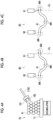
- the accumulation unit 70 is a device that accumulates a plurality of formed products 41. As shown in Fig. 4A , in the accumulation unit 70, the transport device 110C grips the formed product 41 formed by the forming device 1 and places the formed product 41 on an accumulation bogie 71. The transport device 110C accumulates the formed product 41 by repeating the operation to stack the formed product 41 on the accumulation bogie 71.
- a worker transports the accumulation bogie 71 in which the formed products 41 are accumulated in the accumulation unit 70 to the inspection device 81 in the treatment area E5.
- the inspection device 81 inspects the formed product 41.
- the inspection device 81 inspects the shape of the formed product 41 and displays an error on the formed product that does not satisfy predetermined criteria.
- the worker transports the passed formed product 41 to the scale removing device 82.
- the scale removing device 82 removes oxidized scales generated in the formed product 41 during forming.
- the scale removing device 82 removes the scales by, for example, shot blasting or wet blasting.
- the worker accumulates the formed product 41, from which the scales have been removed, on the accumulation bogie of the accumulation unit 83.
- the formed product 41 of the accumulation unit 83 is transported to the post-machining device 90 in the machining area E6 by the transport device 110D.
- the post-machining device 90 in the machining area E6 irradiates the formed product 41 with a laser beam to perform machining such as drilling, notch forming, and cutting.
- the post-machining device 90 includes a laser head 91 (machining unit). The post-machining device 90 moves the laser head 91 in accordance with the machining content while irradiating the formed product 41 from the laser head 91.
- the forming system 100 has a function of constraining the relative position and relative phase of the positioned metal pipe material 40 so as not to change until the forming is performed by the forming device 1.
- the metal pipe material 40 continues being gripped by at least one of the transport devices 110A and 110B and any of the devices 1 and 60.
- the metal pipe material 40 continues being gripped by any of the transport devices 110A and 110B, the forming device 1, and the heating device 60 from when the metal pipe material 40 is gripped by the transport device 110A by the positioning portion 50 to when the forming is performed by the forming device 1.
- the transport device 110A sandwiches the metal pipe material 40 in a state of being positioned by the positioning portion 50 between the gripping members 101 and 102, thereby gripping the metal pipe material 40.
- the transport device 110A has a structure in which the position and angle of the metal pipe material 40 with respect to the gripping members 101 and 102 do not deviate before and after the metal pipe material 40 on the positioning portion 50 is gripped.
- the transport device 110A transports the metal pipe material 40 to the heating device 60 while being gripped by the gripping members 101 and 102.
- the transport device 110A does not release the gripping of the metal pipe material 40 or does not change the gripped state (for example, change the position or angle to grip) during the transport.
- the transport device 110A positions the metal pipe material 40 with respect to the heating device 60 while gripping the metal pipe material 40.
- the transport device 110A performs the positioning on the basis of information such as the position and angle at which the metal pipe material 40 is gripped.
- the heating device 60 grips both ends of the metal pipe material 40 with the electrodes 61 and 62.
- the gripping portion 100A releases the gripping of the metal pipe material 40 and returns the gripping members 101 and 102 to the positioning portion 50 again.
- the transport device 110B grips the metal pipe material 40 by sandwiching the heated metal pipe material 40 between the gripping members 101 and 102.
- the transport device 110B has a structure in which the position and angle of the metal pipe material 40 on the heating device 60 with respect to the gripping members 101 and 102 do not deviate before and after the gripping.
- the heating device 60 releases the gripping performed by the electrodes 61 and 62.
- the transport device 110B transports the metal pipe material 40 to the forming device 1 while being gripped by the gripping members 101 and 102.
- the transport device 110B does not release the gripping of the metal pipe material 40 or does not change the gripped state (for example, change the position or angle to grip) during the transport.
- the transport device 110B performs positioning with respect to the forming device 1 while gripping the metal pipe material 40.
- the transport device 110B has a structure in which the position and angle of the metal pipe material 40 with respect to the gripping members 101 and 102 do not deviate before and after the gripping.
- the forming device 1 grips both ends of the metal pipe material 40 with the retaining members 26 and 27.
- the gripping portion 100B releases the gripping of the metal pipe material 40 and returns the gripping members 101 and 102 to the heating device 60 side again.
- the metal pipe material 40 disposed in the forming device 1 becomes a formed product 41 after the forming.
- the forming device 1 performs marking with respect to the formed product 41.
- the forming device 1 has a marking unit 120.
- the marking unit 120 performs marking with respect to an outer peripheral surface of the formed product 41.
- the marking unit 120 includes a pin 121, a pin support mechanism 122, a hydraulic chamber 123, and a hydraulic oil supply unit 124, for example, in the case of performing marking with a pin.
- the pin 121 is disposed in a lower die 11 and is reciprocable in the vertical direction. When the marking is not performed, the pin 121 is accommodated in the lower die 11 so as not to protrude from a forming surface 11a. The pin 121 protrudes from the forming surface 11a when the marking is performed.
- the pin support mechanism 122 is a mechanism that supports the pin 121 in the lower die 11.
- the pin support mechanism 122 supports the pin 121 so as to be reciprocable in the vertical direction.
- the pin support mechanism 122 includes a spring member 122a. In a case where the pin 121 has protruded from the forming surface 11a, the spring member 122a applies an elastic force in the direction of returning the pin 121 to an original position thereof.
- the hydraulic chamber 123 is an internal space formed in the lower die 11. A proximal end portion of the pin 121 is exposed in the hydraulic chamber 123.
- the hydraulic oil supply unit 124 supplies hydraulic oil to the hydraulic chamber 123.
- the hydraulic oil supply unit 124 supplies the hydraulic oil to the hydraulic chamber 123
- the proximal end portion of the pin 121 receives pressure, and the pin 121 protrudes from the forming surface 11a. Accordingly, a recess, or a mark resulting from a through-hole is formed on the outer peripheral surface of the formed product 41.
- the hydraulic oil is discharged from the hydraulic chamber 123, the pressure on the proximal end portion of the pin 121 is released, and the pin 121 returns to the original position.
- the hydraulic mechanism as described above does not need to be built in the lower die 11, but may be built in a die holder or a press device.
- the timing at which the pin 121 protrudes from the forming surface to perform the marking is not particularly limited.
- the pin 121 may perform the marking at the timing at which the temperature of the formed product 41 has dropped to some extent after the forming is completed.
- the mark can be added after the formed product 41, which has been expanded by the heating, has contracted through cooling.
- the above-described marking unit 120 accommodates the pin 121 in the lower die 11 during the forming of the forming device 1. After the forming is completed, the marking unit 120 protrudes the pin 121 from the forming surface 11a to press the pin 121 against the formed product 41. Accordingly, the mark is given to the formed product 41.
- the marking unit 120 may be provided, for example, at spots corresponding to both end portions of the formed product 41 or at a spot corresponding to a central position of the formed product 41, in the lower die 11. Additionally, the marking unit 120 may be provided at spots corresponding to both end portions of the formed product 41 or at a spot corresponding to the central position of the formed product 41, in the upper die 12. However, the number and location of the marking units 120 are not particularly limited.
- the marking units 120 are at two or more spots including positions as apart as possible.
- the mark may be any means as long as the coordinates can be specified.
- the mark may be an intersection line resulting from marking-off or may be drilling.
- the post-machining device 90 detects a mark MK formed by the marking. Additionally, the post-machining device 90 detects the mark MK and corrects a position between the laser head 91 and the formed product 41 on the basis of a result of the detection. As shown in Fig. 4B , the post-machining device 90 includes a detection unit 92 that detects the mark MK.
- the detection unit 92 is constituted by, for example, a camera. The detection unit 92 detects the position of the mark MK on the basis of a captured image.
- the post-machining device 90 calculates the relative deviation between a preset machining work locus and the formed product 41 gripped in the post-machining device 90 on the basis of the detected position of the mark MK, and the post-machining device 90 calculates the correction amount of the machining work locus . Then, as shown in Fig. 4C , in a case where deviation occurs between the laser head 91 and a cutting line CL, the post-machining device 90 moves the laser head 91 to the position of the cutting line CL to correct the deviation.
- the forming system 100 expands and deforms the metal pipe material 40 to perform high-pressure gas expansion forming.
- a type of forming system 100 since it is necessary to expand the metal material during the forming, it is not possible to form a reference hole for clarifying a reference position in the preliminary stage of the forming process. If the reference hole can be provided, the metal pipe material 40 can be easily positioned by inserting a positioning pin or the like into the reference hole, and the formed product 41 can be positioned using the reference hole even the machining in the post-machining device 90.
- the high-pressure gas expansion forming if such a reference hole is formed in the metal pipe material 40, high-pressure gas leaks from the reference hole, and the forming cannot be performed.
- the forming system 100 is a forming system 100 that expands and deforms the metal pipe material 40 to perform the forming, and includes a forming device 1 that performs the forming and the transport device that transports the metal pipe material 40.
- the transport device transports the metal pipe material 40 to the forming device 1 in a gripped state.
- the transport device transports the metal pipe material 40 to the heating device 60 in a gripped state.
- the forming system 100 during the period from the transport process in which the metal pipe material 40 is transported to any of the devices 1 and 60 by the transport device to the treatment process performed by any of the devices 1 and 60, at least one of the transport device and any of the devices 1,60 continues gripping the metal pipe material 40. That is, during the period from the transport process in which the metal pipe material 40 is transported to the forming device 1 by the transport device 110B to a forming treatment process performed by the forming device 1, at least one of the transport device 110B and the forming device 1 continues gripping the metal pipe material 40.
- the heating device 60 during the period from the transport process in which the metal pipe material 40 is transported to the heating device 60 by the transport device 110A to a heating process performed by the heating device 60, at least one of the transport device 110A and the heating device 60 continues gripping the metal pipe material 40.
- the forming system 100 may execute the treatment process while maintaining a state in which the position of the metal pipe material 40 is aligned. That is, it is possible to continue constraining the metal pipe material 40 in the forming device 1 and the heating device 60 so as not to have a positional deviation and a phase deviation, and to execute the forming treatment and the heat treatment. From the above, the accuracy of a product using the formed product 41 can be improved.
- the forming system 100 further includes the positioning portion 50 that positions the metal pipe material 40 in a part of the pretreatment device, and the transport device 110A and 110B grip the metal pipe material 40 in a state of being positioned by the positioning portion 50, the metal pipe material 40 continues being gripped by any of the transport device 110A and 110B, the forming device 1, and the heating device 60 in a case where this heating device 60 is present, from when the metal pipe material 40 is gripped by the transport device 110A and 110B by the positioning portion 50 to when the forming is performed by the forming device 1.
- the forming system 100 can perform the forming treatment in the forming device 1 while maintaining a state in which the position of the metal pipe material 40 is aligned by the positioning portion 50.
- the forming system 100 is the forming system 100 that expands and deforms the metal pipe material 40 to perform the forming, and includes the forming device 1 that performs the forming and the post-machining device 90 that performs the machining of the formed product 41 formed by the forming device 1, the forming device 1 performs marking with respect to the formed product 41, and the post-machining device 90 detects the mark formed by the marking to perform correction calculation of a machining position based on the marking position to perform predetermined machining.
- the forming device 1 performs marking with respect to the formed product 41, and the post-machining device 90 detects the mark formed by the marking.
- the forming device 1 performs marking on the formed product 41 after the expansion and deformation.
- the marking serves to mark an accurate relative position with respect to product shape . Therefore, in the post-process of the forming process, the post-machining device 90 can perform highly accurate machining by using information obtained by the marking. Additionally, the post-machining device 90 can perform reference hole and notch machining using the detection result of the marking, thereby utilizing the same assembly process as the related-art car body assembly process.
- the forming device 1 can perform the forming while maintaining the positioning state in the positioning portion 50. For that reason, the forming device 1 can perform marking with respect to the formed product 41 in a state in which the positional deviation and the phase deviation are suppressed. Therefore, the post-machining device 90 can perform the machining by using the position information of the marking written at an accurate relative position with respect to a die forming surface. From the above, the accuracy of a product using the formed product 41 can be improved.
- the post-machining device 90 detects the mark, corrects the relative position of the machining based on the mark position where the machining position with respect to the formed product 41 is written at the accurate relative position, on the basis of a result of the detection, and performs the predetermined machining. Accordingly, the post-machining device 90 can perform highly accurate machining on the basis of the detection result of the mark.
- the forming system is a forming system that expands and deforms a metal material to perform forming, and includes a forming device that performs the forming, and a transport device that transports the metal material, and a post-machining device that machines a formed product formed by the forming device.
- the transport device transports the metal material to the forming device in a held state.
- the pretreatment device that performs pretreatment for the forming is present, the transport device transports the metal material to the pretreatment device in a held state.
- the metal material continues being held by at least one of the transport device or any of the devices.
- the forming device performs marking with respect to the formed product.
- the post-machining device detects the mark formed by the marking.
- the present invention is not limited to the above-described embodiment.
- the pretreatment device may not be present on the upstream side of the forming device. That is, the heating device may not be present.
- the forming device has an electrode for energization and heating.
- a device other than the heating device may be present.
- the transport device is not limited to the robot or the like. That is, the transport device may be any of the devices as long as the transport device can transport the metal pipe material while holding the metal pipe material in a state in which at least the position and phase are maintained.
- the mechanism that performs the marking is not limited to the above-described embodiment.
- the marking is not performed during the forming, and after the forming is completed, the drive mechanism drives the pin to perform the marking.
- a drive mechanism may be omitted, and a configuration in which the pin always protrudes from the forming surface may be adopted.
- marking is performed at the same time that the metal pipe material comes into contact with the forming surface.
- the marking can be performed after the product shape is frozen, which is less affected by cooling contraction or the like.
- the post-machining device may detect the mark by methods other than capturing performed by a camera.
- the post-machining device may detect the mark by a contact sensor or the like.
- the forming method is not particularly limited as long as a forming method that performs the forming by expansion deformation is provided.
- forming methods such as hydroforming may be adopted.
- the machining unit is not limited to the post-machining device, and devices using other machining methods may be adopted.
Landscapes
- Engineering & Computer Science (AREA)
- Mechanical Engineering (AREA)
- Chemical & Material Sciences (AREA)
- Physics & Mathematics (AREA)
- Fluid Mechanics (AREA)
- Organic Chemistry (AREA)
- Crystallography & Structural Chemistry (AREA)
- Materials Engineering (AREA)
- Metallurgy (AREA)
- Thermal Sciences (AREA)
- Plasma & Fusion (AREA)
- Optics & Photonics (AREA)
- Manufacturing & Machinery (AREA)
- Shaping Metal By Deep-Drawing, Or The Like (AREA)
- Laser Beam Processing (AREA)
- Injection Moulding Of Plastics Or The Like (AREA)
- Casting Or Compression Moulding Of Plastics Or The Like (AREA)
- Specific Conveyance Elements (AREA)
Abstract
Description
- An aspect of the present invention relates to a forming system.
- In the related art, a forming system described in
PTL 1 is known. This forming system has a heating unit that heats a metal material, a fluid supply unit that supplies a fluid to the heated metal material, and a forming die that forms the heated metal material. The forming device obtains a shape corresponding to a forming surface as the shape of the metal material by bringing the forming surface of the forming die into contact with the heated metal material. - [PTL 1]
Japanese Unexamined Patent Publication No. 2009-220141 - Here, the forming system described in
PTL 1 described above expands and deforms the metal material to perform the forming. In such a type of forming system, since it is necessary to expand the metal material during the forming, it is not possible to form a reference hole for clarifying a reference position in a preliminary stage of a forming process. Even in a situation where such a reference hole cannot be provided, it is required to improve the accuracy of a product using a formed product. - An aspect of the present invention has been made to solve such a problem, and an object of the present invention is to provide a forming system capable of improving the accuracy of a product using a formed product.
- The forming system according to an aspect of the present invention is a forming system that expands and deforms a metal material to perform forming. The forming system includes a forming device that performs the forming; and at least one transport device that transports the metal material. The transport device transports the metal material to the forming device in a held state. In a case where a pretreatment device that performs pretreatment for the forming is present, the transport device transports the metal material to the pretreatment device in a held state. During a period from a transport process in which the metal material is transported to any of devices by the transport device to a treatment process performed by any of the devices, at least one of the transport device and any of the devices continues holding the metal material.
- In the forming system, the transport device transports the metal material to the forming device in a held state, and in a case where the pretreatment device that performs pretreatment for forming is present, the transport device transports the metal material to the pretreatment device in a held state. In contrast, during the period from the transport process in which the metal material is transported to any of the devices by the transport device to the treatment process performed by any of the devices, at least one of the transport device and any of the devices continues holding the metal material. That is, during the period from the transport process in which the metal material is transported to the forming device by the transport device to the forming treatment process performed by the forming device, at least one of the transport device and the forming device continues holding the metal material. Additionally, in a case where the pretreatment device is present, during the period from the transport process in which the metal material is transported to the pretreatment device by the transport device to the pretreatment process performed by the pretreatment device, at least one of the transport device and the pretreatment device continues holding the metal material. In this case, in a case where the metal material has been positioned in the preliminary stage of the transport process, the forming system may execute the treatment process while maintaining a state in which the position of the metal material is aligned. That is, it is possible to continue constraining the metal material so as to suppress the positional deviation and the phase deviation of the metal material in the forming device and the pretreatment device, and to execute the forming treatment and the pretreatment. From the above, the accuracy of a product using the formed product can be improved.
- The forming system may further include a positioning portion that positions the metal material in a part of the pretreatment device. The transport device may hold the metal material in a state of being positioned in the positioning portion. The metal material may continue being held by any of the pretreatment device, the forming device, and the pretreatment device in a case where the pretreatment device is present, from when the metal material is held by the transport device in the positioning portion to when the forming is performed by the forming device. In this case, the forming system can perform the forming treatment in the forming device while maintaining a state in which the position of the metal material is aligned by the positioning portion.
- The forming system further includes a post-machining device that machines a formed product formed by the forming device. The forming device performs marking with respect to the formed product. The post-machining device detects a mark formed by the marking. Although it is not possible to form a reference hole or the like in the metal material in the preliminary stage of the forming process accompanied by the expansion and deformation, here, the forming device performs marking on the formed product after the expansion and deformation. The marking serves to mark an accurate relative position with respect to product shape. Therefore, in the post-process of the forming process, the post-machining device can perform highly accurate machining by using information obtained by the marking. From the above, the accuracy of a product using the formed product can be improved.
- The forming system according to an aspect of the present invention is a forming system that expands and deforms a metal material to perform forming. The forming system includes a forming device that performs the forming; and a post-machining device that machines a formed product formed by the forming device. The forming device performs marking with respect to the formed product. The post-machining device detects a mark formed by the marking.
- In the forming system, the forming device performs marking with respect to the formed product, and the post-machining device detects a mark formed by the marking. Although it is not possible to form a reference hole or the like in the metal material in the preliminary stage of the forming process accompanied by the expansion and deformation, here, the forming device performs marking on the formed product after the expansion and deformation. The marking serves to mark an accurate relative position with respect to product shape. Therefore, in the post-process of the forming process, the post-machining device can perform highly accurate machining by using information obtained by the marking. From the above, the accuracy of a product using the formed product can be improved.
- The post-machining device may detect the mark, correct a machining position of the formed product on the basis of a result of the detection, and perform predetermined machining. Accordingly, the post-machining device can perform highly accurate machining on the basis of the detection result of the mark.
- Provided is a forming system that expands and deforms a metal material to perform forming. The forming system includes a forming device that performs the forming; at least one transport device that transports the metal material; and a post-machining device that machines a formed product formed by the forming device. The transport device transports the metal material to the forming device in a held state. In a case where a pretreatment device that performs pretreatment for the forming is present, the transport device transports the metal material to the pretreatment device in a held state. During a period from a transport process in which the metal material is transported to any of the devices by the transport device to a treatment process performed any of the devices, at least one of the transport device and any of the devices continues holding the metal material. The forming device performs marking with respect to the formed product. The post-machining device detects a mark formed by the marking.
- According to the forming system, in the forming system, the transport device transports the metal material to the forming device in a held state, and in a case where a pretreatment device that performs pretreatment for the forming is present, the transport device transports the metal material to the pretreatment device in a held state. In contrast, during the period from the transport process in which the metal material is transported to any of the devices by the transport device to the treatment process performed by any of the devices, at least one of the transport device and any of the devices continues holding the metal material. That is, during the period from the transport process in which the metal material is transported to the forming device by the transport device to the forming treatment process performed by the forming device, at least one of the transport device and the forming device continues holding the metal material. Additionally, in a case where the pretreatment device is present, during the period from the transport process in which the metal material is transported to the pretreatment device by the transport device to the pretreatment process performed by the pretreatment device, at least one of the transport device and the pretreatment device continues holding the metal material. In this case, in a case where the metal material has been positioned in the preliminary stage of the transport process, the forming system may execute the treatment process while maintaining a state in which the position of the metal material is aligned. That is, it is possible to continue constraining the metal material so as to suppress the positional deviation and the phase deviation of the metal material in the forming device and the pretreatment device, and to execute the forming treatment and the pretreatment. From the above, the accuracy of a product using the formed product can be improved. Additionally, in the forming system, the forming device performs marking with respect to the formed product, and the post-machining device detects a mark formed by the marking. Although it is not possible to form a reference hole or the like in the metal material in the preliminary stage of the forming process accompanied by the expansion and deformation, here, the forming device performs marking on the formed product after the expansion and deformation. The marking serves to mark an accurate relative position with respect to product shape. Therefore, in the post-process of the forming process, the post-machining device can perform highly accurate machining by using information obtained by the marking. From the above, the accuracy of a product using the formed product can be improved.
- According to an aspect of the present invention, it is possible to provide the forming system capable of improving the accuracy of a product using the formed product.
-
-
Fig. 1 is a schematic diagram of a forming device used in a forming system according to the present embodiment. -
Fig. 2 is an example of a conceptual diagram showing a configuration of the forming system according to the present embodiment. -
Figs. 3A to 3F are schematic diagrams showing a holding state of a metal pipe material in each device. -
Figs. 4A to 4C are schematic diagrams showing a treatment process of a formed product after forming. -
Fig. 5 is a cross-sectional view showing a marking unit of a forming device. - Hereinafter, preferred embodiments of the present invention will be described with reference to the drawings. In addition, in the respective drawings, the same portions or corresponding portions are designated by the same reference numerals, and duplicated descriptions will be omitted.
-
Fig. 1 is a schematic diagram of the formingdevice 1 used in the formingsystem 100 according to the present embodiment. As shown inFig. 1 , the formingdevice 1 is a device that forms a heated metal material with a forming die. In the present embodiment, a STAF forming device, which performs the forming and hardening by supplying a fluid to a heated metal pipe material to bring the fluid into contact with a forming surface of the forming die, is adopted as the formingdevice 1. In the present embodiment, the formingdevice 1 is installed on a horizontal plane. The formingdevice 1 includes a formingdie 2, adrive mechanism 3, a holdingunit 4, afluid supply unit 6, acooling unit 7, and acontrol unit 8. In addition, in the present specification, the metal pipe material 40 (metal material) refers to a hollow article before the completion of the forming by the formingdevice 1. Themetal pipe material 40 is a steel type pipe material that can be hardened. Additionally, in the horizontal direction, a direction in which themetal pipe material 40 extends during forming may be referred to as a "longitudinal direction", and a direction perpendicular to the longitudinal direction may be referred to as a "width direction" . - The forming
die 2 is a die that forms a product from themetal pipe material 40, and includes alower die 11 and anupper die 12 that face each other in a vertical direction. Thelower die 11 and theupper die 12 are made of steel blocks. Each of thelower die 11 and theupper die 12 is provided with a recessed portion in having the forming surface for themetal pipe material 40. With thelower die 11 and theupper die 12 in close contact with each other (die closed state), respective recessed portions thereof form a space having a target shape in which the metal pipe material is to be formed. Therefore, the surfaces of the respective recessed portions become the forming surfaces of the formingdie 2. Thelower die 11 is fixed to abase stage 13 via a die holder or the like. Theupper die 12 is fixed to a slide of thedrive mechanism 3 via a die holder or the like. - The
drive mechanism 3 is a mechanism that moves at least one of thelower die 11 and theupper die 12. InFig. 1 , thedrive mechanism 3 has a configuration in which only theupper die 12 is moved. Thedrive mechanism 3 includes aslide 21 that moves theupper die 12 such that thelower die 11 and theupper die 12 are joined together, and a pull-back cylinder 22 serving as an actuator that generates a force for pulling theslide 21 upward, amain cylinder 23 serving as a drive source that downward-pressurizes theslide 21, and adrive source 24 that applies a driving force to themain cylinder 23. - The holding
unit 4 is a mechanism that holds themetal pipe material 40 disposed between thelower die 11 and theupper die 12. The holdingunit 4 includes a retainingmember 26 and a retainingmember 27 that hold themetal pipe material 40 on one end side of the formingdie 2 in the longitudinal direction, and a retainingmember 26 and a retainingmember 27 on both sides in the longitudinal direction sandwich the vicinity of the end portion of themetal pipe material 40 from the vertical direction to hold themetal pipe material 40. In addition, groove portions having a shape corresponding to an outer peripheral surface of themetal pipe material 40 are formed on an upper surface of the retainingmember 26 and a lower surface of the retainingmember 27. The retainingmember 26 and the retainingmember 27 are provided with drive mechanisms (not shown) and are movable independently in the vertical direction. - The
fluid supply unit 6 is a mechanism that supplies a high-pressure fluid into themetal pipe material 40 held between thelower die 11 and theupper die 12. Thefluid supply unit 6 supplies the high-pressure fluid to themetal pipe material 40 that has been brought into a high-temperature state by being heated, and expands themetal pipe material 40. Thefluid supply unit 6 is provided on both end sides of the formingdie 2 in the longitudinal direction. Thefluid supply unit 6 includes anozzle 31 that supplies fluid from an opening of an end portion of themetal pipe material 40 to the inside of themetal pipe material 40, and adrive mechanism 32 that moves thenozzle 31 forward and backward with respect to the opening of themetal pipe material 40, and asupply source 33 that supplies the high-pressure fluid into themetal pipe material 40 via thenozzle 31. In thedrive mechanism 32, thenozzle 31 is brought into close contact with the end portion of themetal pipe material 40 in a state in which the sealing performance is secured during fluid supply and exhaust, and at other times, thenozzle 31 is spaced apart from the end portion of themetal pipe material 40. In addition, thefluid supply unit 6 may supply a gas such as high-pressure air or an inert gas as the fluid. Additionally, thefluid supply unit 6 may be the same device together with the holdingunit 4 having a mechanism that moves themetal pipe material 40 in the vertical direction. In this case, abase member 38 that supports thefluid supply unit 6, and the holdingunit 4 may be connected to each other by aconnection member 39. - The
cooling unit 7 is a mechanism that cools the formingdie 2. By cooling the formingdie 2, thecooling unit 7 can rapidly cool themetal pipe material 40 when the expandedmetal pipe material 40 has come into contact with a forming surface of the formingdie 2. Thecooling unit 7 includes aflow path 36 formed inside thelower die 11 and theupper die 12, and awater circulation mechanism 37 that supplies and circulates cooling water to theflow path 36. - The
control unit 8 is a device that controls the entire formingdevice 1. Thecontrol unit 8 controls thedrive mechanism 3, the holdingunit 4, thefluid supply unit 6, and thecooling unit 7. Thecontrol unit 8 repeatedly performs an operation of forming themetal pipe material 40 with the formingdie 2. - Specifically, the
control unit 8 controls, for example, the transport timing from a transport device such as a robot arm to dispose themetal pipe material 40 between thelower die 11 and theupper die 12 in an open state. Additionally, thecontrol unit 8 supports themetal pipe material 40 with the retainingmembers 26 on both sides in the longitudinal direction, and then controls the actuator of the holdingunit 4 so as to lower the retainingmember 27 to sandwich themetal pipe material 40. - The
control unit 8 controls thedrive mechanism 3 to lower theupper die 12 and bring theupper die 12 closer to thelower die 11 to close the formingdie 2. On the other hand, thecontrol unit 8 controls thefluid supply unit 6 to seal the openings of both ends of themetal pipe material 40 with thenozzle 31 and supply the fluid. Accordingly, themetal pipe material 40 softened by heating expands and comes into contact with the forming surface of the formingdie 2. Then, themetal pipe material 40 is formed so as to follow the shape of the forming surface of the formingdie 2. In addition, in a case where a metal pipe with a flange is formed, a part of themetal pipe material 40 is made to enter a gap between thelower die 11 and theupper die 12, and then the die is further closed to crush the entering portion to form a flange portion. When themetal pipe material 40 comes into contact with the forming surface, hardening of themetal pipe material 40 is performed by being quenched with the formingdie 2 cooled by thecooling unit 7. - As described above, the forming
device 1 expands and deforms themetal pipe material 40 to perform forming. For this reason, it is not possible to provide a structure in which a hole is made in themetal pipe material 40 to allow the fluid to leak in a preliminary stage in which themetal pipe material 40 expands in the formingdevice 1. For that reason, it is not possible to form a positioning hole in themetal pipe material 40 in the preliminary stage of the forming. For that reason, the formingsystem 100 according to the present embodiment includes a structure for performing forming with the formingdevice 1 in a state in which themetal pipe material 40 is positioned. -
Fig. 2 is an example of a conceptual diagram showing the configuration of the formingsystem 100 according to the present embodiment. As shown inFig. 2 , the formingsystem 100 includes a metal pipe material preparation area E1, a heating area E2, a forming area E3, an accumulation area E4, a treatment area E5, and a machining area E6. Additionally, the formingsystem 100 includes apositioning portion 50 in the metal pipe material preparation area E1, aheating device 60 in the heating area E2, the formingdevice 1 in the forming area E3, anaccumulation unit 70 in the accumulation area E4, aninspection device 81, ascale removing device 82, and anaccumulation unit 83 in the treatment area E5, apost-machining device 90 in the machining area E6, andtransport devices 110A to 110D disposed in the respective areas. Thetransport devices 110A to 110D are configured by transport devices such as robots. - In the metal pipe material preparation area E1, the
metal pipe material 40 is prepared. Additionally, in the metal pipe material preparation area E1, themetal pipe material 40 is positioned by the positioningportion 50 as shown inFig. 3A . The positioningportion 50 positions themetal pipe material 40 by three-point support, for example, as shown inFig. 3A . That is, the positioningportion 50 includessupport portions metal pipe material 40, and asupport portion 51C that supports a central position of themetal pipe material 40 in the longitudinal direction. For example, the positioningportion 50 can determine the phase of themetal pipe material 40 by thesupport portions positioning portion 50, the metal pipe material is positioned in the longitudinal direction by pressing one end portion of themetal pipe material 40 against awall portion 52. - Returning to
Fig. 2 , themetal pipe material 40 positioned by the positioningportion 50 is transported to theheating device 60 in the heating area E2 by thetransport device 110A. In the heating area E2, the metal pipe material is heated by theheating device 60. As shown inFig. 3C , theheating device 60 includes two sets ofelectrodes electrodes metal pipe material 40. The other set ofelectrodes metal pipe material 40. Theheating device 60 is a mechanism that heats themetal pipe material 40 by energizing themetal pipe material 40 via theelectrodes heating device 60 allows a high electric current to flow between one set ofelectrodes electrodes metal pipe material 40, and the electric resistance of themetal pipe material 40 itself causes themetal pipe material 40 itself to generate heat due to Joule heat. - Returning to
Fig. 2 , themetal pipe material 40 heated by theheating device 60 is transported to the formingdevice 1 in the forming area E3 by thetransport device 110B. In the forming area E3, themetal pipe material 40 is formed by the formingdevice 1. Accordingly, the formedproduct 41 is formed (seeFigs. 4A to 4C ). - The formed
product 41 formed by the formingdevice 1 is accumulated in theaccumulation unit 70 in the accumulation area E4 by thetransport device 110C. Theaccumulation unit 70 is a device that accumulates a plurality of formedproducts 41. As shown inFig. 4A , in theaccumulation unit 70, thetransport device 110C grips the formedproduct 41 formed by the formingdevice 1 and places the formedproduct 41 on anaccumulation bogie 71. Thetransport device 110C accumulates the formedproduct 41 by repeating the operation to stack the formedproduct 41 on theaccumulation bogie 71. - Returning to
Fig. 2 , a worker transports theaccumulation bogie 71 in which the formedproducts 41 are accumulated in theaccumulation unit 70 to theinspection device 81 in the treatment area E5. Theinspection device 81 inspects the formedproduct 41. Theinspection device 81 inspects the shape of the formedproduct 41 and displays an error on the formed product that does not satisfy predetermined criteria. Next, the worker transports the passed formedproduct 41 to thescale removing device 82. Thescale removing device 82 removes oxidized scales generated in the formedproduct 41 during forming. Thescale removing device 82 removes the scales by, for example, shot blasting or wet blasting. The worker accumulates the formedproduct 41, from which the scales have been removed, on the accumulation bogie of theaccumulation unit 83. - The formed
product 41 of theaccumulation unit 83 is transported to thepost-machining device 90 in the machining area E6 by thetransport device 110D. As shown inFig. 2 , thepost-machining device 90 in the machining area E6 irradiates the formedproduct 41 with a laser beam to perform machining such as drilling, notch forming, and cutting. As shown inFigs. 4B and 4C , thepost-machining device 90 includes a laser head 91 (machining unit). Thepost-machining device 90 moves thelaser head 91 in accordance with the machining content while irradiating the formedproduct 41 from thelaser head 91. - The forming
system 100 according to the present embodiment has a function of constraining the relative position and relative phase of the positionedmetal pipe material 40 so as not to change until the forming is performed by the formingdevice 1. - Specifically, in the forming
system 100, during a period from a transport process in which themetal pipe material 40 is transported to any of thedevices transport devices devices metal pipe material 40 continues being gripped by at least one of thetransport devices devices metal pipe material 40 continues being gripped by any of thetransport devices device 1, and theheating device 60 from when themetal pipe material 40 is gripped by thetransport device 110A by the positioningportion 50 to when the forming is performed by the formingdevice 1. - More specifically, as shown in
Fig. 3B , thetransport device 110A sandwiches themetal pipe material 40 in a state of being positioned by the positioningportion 50 between thegripping members metal pipe material 40. In this case, thetransport device 110A has a structure in which the position and angle of themetal pipe material 40 with respect to the grippingmembers metal pipe material 40 on thepositioning portion 50 is gripped. Thetransport device 110A transports themetal pipe material 40 to theheating device 60 while being gripped by the grippingmembers transport device 110A does not release the gripping of themetal pipe material 40 or does not change the gripped state (for example, change the position or angle to grip) during the transport. - As shown in
Fig. 3C , thetransport device 110A positions themetal pipe material 40 with respect to theheating device 60 while gripping themetal pipe material 40. In this case, thetransport device 110A performs the positioning on the basis of information such as the position and angle at which themetal pipe material 40 is gripped. After the positioning of thetransport device 110A is completed, theheating device 60 grips both ends of themetal pipe material 40 with theelectrodes Fig. 3D , when the gripping by theelectrodes portion 100A releases the gripping of themetal pipe material 40 and returns the grippingmembers positioning portion 50 again. - Next, the
transport device 110B grips themetal pipe material 40 by sandwiching the heatedmetal pipe material 40 between thegripping members transport device 110B has a structure in which the position and angle of themetal pipe material 40 on theheating device 60 with respect to the grippingmembers transport device 110B is completed, theheating device 60 releases the gripping performed by theelectrodes transport device 110B transports themetal pipe material 40 to the formingdevice 1 while being gripped by the grippingmembers transport device 110B does not release the gripping of themetal pipe material 40 or does not change the gripped state (for example, change the position or angle to grip) during the transport. - As shown in
Fig. 3E , thetransport device 110B performs positioning with respect to the formingdevice 1 while gripping themetal pipe material 40. In this case, thetransport device 110B has a structure in which the position and angle of themetal pipe material 40 with respect to the grippingmembers transport device 110B is completed, the formingdevice 1 grips both ends of themetal pipe material 40 with the retainingmembers Fig. 3F , when the gripping is completed, the grippingportion 100B releases the gripping of themetal pipe material 40 and returns the grippingmembers heating device 60 side again. Themetal pipe material 40 disposed in the formingdevice 1 becomes a formedproduct 41 after the forming. - Additionally, the forming
device 1 performs marking with respect to the formedproduct 41. As shown inFig. 5 , the formingdevice 1 has a markingunit 120. The markingunit 120 performs marking with respect to an outer peripheral surface of the formedproduct 41. The markingunit 120 includes apin 121, apin support mechanism 122, a hydraulic chamber 123, and a hydraulicoil supply unit 124, for example, in the case of performing marking with a pin. Thepin 121 is disposed in alower die 11 and is reciprocable in the vertical direction. When the marking is not performed, thepin 121 is accommodated in thelower die 11 so as not to protrude from a forming surface 11a. Thepin 121 protrudes from the forming surface 11a when the marking is performed. Thepin support mechanism 122 is a mechanism that supports thepin 121 in thelower die 11. Thepin support mechanism 122 supports thepin 121 so as to be reciprocable in the vertical direction. Additionally, thepin support mechanism 122 includes aspring member 122a. In a case where thepin 121 has protruded from the forming surface 11a, thespring member 122a applies an elastic force in the direction of returning thepin 121 to an original position thereof. The hydraulic chamber 123 is an internal space formed in thelower die 11. A proximal end portion of thepin 121 is exposed in the hydraulic chamber 123. The hydraulicoil supply unit 124 supplies hydraulic oil to the hydraulic chamber 123. - Accordingly, when the hydraulic
oil supply unit 124 supplies the hydraulic oil to the hydraulic chamber 123, the proximal end portion of thepin 121 receives pressure, and thepin 121 protrudes from the forming surface 11a. Accordingly, a recess, or a mark resulting from a through-hole is formed on the outer peripheral surface of the formedproduct 41. When the hydraulic oil is discharged from the hydraulic chamber 123, the pressure on the proximal end portion of thepin 121 is released, and thepin 121 returns to the original position. In addition, the hydraulic mechanism as described above does not need to be built in thelower die 11, but may be built in a die holder or a press device. In addition, the timing at which thepin 121 protrudes from the forming surface to perform the marking is not particularly limited. However, thepin 121 may perform the marking at the timing at which the temperature of the formedproduct 41 has dropped to some extent after the forming is completed. In this case, the mark can be added after the formedproduct 41, which has been expanded by the heating, has contracted through cooling. - The above-described
marking unit 120 accommodates thepin 121 in thelower die 11 during the forming of the formingdevice 1. After the forming is completed, the markingunit 120 protrudes thepin 121 from the forming surface 11a to press thepin 121 against the formedproduct 41. Accordingly, the mark is given to the formedproduct 41. The markingunit 120 may be provided, for example, at spots corresponding to both end portions of the formedproduct 41 or at a spot corresponding to a central position of the formedproduct 41, in thelower die 11. Additionally, the markingunit 120 may be provided at spots corresponding to both end portions of the formedproduct 41 or at a spot corresponding to the central position of the formedproduct 41, in theupper die 12. However, the number and location of the markingunits 120 are not particularly limited. For example, it is preferable that the markingunits 120 are at two or more spots including positions as apart as possible. Additionally, the mark may be any means as long as the coordinates can be specified. For example, in addition to the mark resulting from the pin, the mark may be an intersection line resulting from marking-off or may be drilling. - As shown in
Figs. 4B and 4C , thepost-machining device 90 detects a mark MK formed by the marking. Additionally, thepost-machining device 90 detects the mark MK and corrects a position between thelaser head 91 and the formedproduct 41 on the basis of a result of the detection. As shown inFig. 4B , thepost-machining device 90 includes adetection unit 92 that detects the mark MK. Thedetection unit 92 is constituted by, for example, a camera. Thedetection unit 92 detects the position of the mark MK on the basis of a captured image. Then, thepost-machining device 90 calculates the relative deviation between a preset machining work locus and the formedproduct 41 gripped in thepost-machining device 90 on the basis of the detected position of the mark MK, and thepost-machining device 90 calculates the correction amount of the machining work locus . Then, as shown inFig. 4C , in a case where deviation occurs between thelaser head 91 and a cutting line CL, thepost-machining device 90 moves thelaser head 91 to the position of the cutting line CL to correct the deviation. - Next, the operation and effects of the forming
system 100 according to the present embodiment will be described. - The forming
system 100 expands and deforms themetal pipe material 40 to perform high-pressure gas expansion forming. In such a type of formingsystem 100, since it is necessary to expand the metal material during the forming, it is not possible to form a reference hole for clarifying a reference position in the preliminary stage of the forming process. If the reference hole can be provided, themetal pipe material 40 can be easily positioned by inserting a positioning pin or the like into the reference hole, and the formedproduct 41 can be positioned using the reference hole even the machining in thepost-machining device 90. However, in the high-pressure gas expansion forming, if such a reference hole is formed in themetal pipe material 40, high-pressure gas leaks from the reference hole, and the forming cannot be performed. - In contrast, the forming
system 100 according to the present embodiment is a formingsystem 100 that expands and deforms themetal pipe material 40 to perform the forming, and includes a formingdevice 1 that performs the forming and the transport device that transports themetal pipe material 40. The transport device transports themetal pipe material 40 to the formingdevice 1 in a gripped state. In a case where a heating device (pretreatment device) that performs pretreatment for the forming is present, the transport device transports themetal pipe material 40 to theheating device 60 in a gripped state. During the period from the transport process in which themetal pipe material 40 is transported to any of thedevices devices devices metal pipe material 40. - In the forming
system 100, during the period from the transport process in which themetal pipe material 40 is transported to any of thedevices devices devices metal pipe material 40. That is, during the period from the transport process in which themetal pipe material 40 is transported to the formingdevice 1 by thetransport device 110B to a forming treatment process performed by the formingdevice 1, at least one of thetransport device 110B and the formingdevice 1 continues gripping themetal pipe material 40. Additionally, in a case where theheating device 60 is present, during the period from the transport process in which themetal pipe material 40 is transported to theheating device 60 by thetransport device 110A to a heating process performed by theheating device 60, at least one of thetransport device 110A and theheating device 60 continues gripping themetal pipe material 40. In this case, in a case where themetal pipe material 40 has been positioned in the preliminary stage of the transport process, the formingsystem 100 may execute the treatment process while maintaining a state in which the position of themetal pipe material 40 is aligned. That is, it is possible to continue constraining themetal pipe material 40 in the formingdevice 1 and theheating device 60 so as not to have a positional deviation and a phase deviation, and to execute the forming treatment and the heat treatment. From the above, the accuracy of a product using the formedproduct 41 can be improved. - The forming
system 100 further includes thepositioning portion 50 that positions themetal pipe material 40 in a part of the pretreatment device, and thetransport device metal pipe material 40 in a state of being positioned by the positioningportion 50, themetal pipe material 40 continues being gripped by any of thetransport device device 1, and theheating device 60 in a case where thisheating device 60 is present, from when themetal pipe material 40 is gripped by thetransport device portion 50 to when the forming is performed by the formingdevice 1. In this case, in the transport process in thetransport device 110A, the heating process in theheating device 60, the transport process in thetransport device 110B, and the forming process in the formingdevice 1, it is possible to continue constraining themetal pipe material 40 so as to have no positional deviation or phase deviation, and guarantee repetition accuracy. Therefore, the formingsystem 100 can perform the forming treatment in the formingdevice 1 while maintaining a state in which the position of themetal pipe material 40 is aligned by the positioningportion 50. - The forming
system 100 according to the embodiment is the formingsystem 100 that expands and deforms themetal pipe material 40 to perform the forming, and includes the formingdevice 1 that performs the forming and thepost-machining device 90 that performs the machining of the formedproduct 41 formed by the formingdevice 1, the formingdevice 1 performs marking with respect to the formedproduct 41, and thepost-machining device 90 detects the mark formed by the marking to perform correction calculation of a machining position based on the marking position to perform predetermined machining. - In the forming
system 100, the formingdevice 1 performs marking with respect to the formedproduct 41, and thepost-machining device 90 detects the mark formed by the marking. Although it is not possible to form the reference hole or the like in themetal pipe material 40 in the preliminary stage of the forming process accompanied by the expansion and deformation, here, the formingdevice 1 performs marking on the formedproduct 41 after the expansion and deformation. The marking serves to mark an accurate relative position with respect to product shape . Therefore, in the post-process of the forming process, thepost-machining device 90 can perform highly accurate machining by using information obtained by the marking. Additionally, thepost-machining device 90 can perform reference hole and notch machining using the detection result of the marking, thereby utilizing the same assembly process as the related-art car body assembly process. In particular, in the present embodiment, as described above, the formingdevice 1 can perform the forming while maintaining the positioning state in thepositioning portion 50. For that reason, the formingdevice 1 can perform marking with respect to the formedproduct 41 in a state in which the positional deviation and the phase deviation are suppressed. Therefore, thepost-machining device 90 can perform the machining by using the position information of the marking written at an accurate relative position with respect to a die forming surface. From the above, the accuracy of a product using the formedproduct 41 can be improved. - The
post-machining device 90 detects the mark, corrects the relative position of the machining based on the mark position where the machining position with respect to the formedproduct 41 is written at the accurate relative position, on the basis of a result of the detection, and performs the predetermined machining. Accordingly, thepost-machining device 90 can perform highly accurate machining on the basis of the detection result of the mark. - The forming system is a forming system that expands and deforms a metal material to perform forming, and includes a forming device that performs the forming, and a transport device that transports the metal material, and a post-machining device that machines a formed product formed by the forming device. The transport device transports the metal material to the forming device in a held state. In a case where the pretreatment device that performs pretreatment for the forming is present, the transport device transports the metal material to the pretreatment device in a held state. During the period from a transport process in which the metal material is transported to any of the devices by the transport device to a treatment process performed by any of the devices, the metal material continues being held by at least one of the transport device or any of the devices. The forming device performs marking with respect to the formed product. The post-machining device detects the mark formed by the marking.
- According to the forming system, the operation and effects having the meaning as that of the above-described forming system can be obtained.
- The present invention is not limited to the above-described embodiment.
- For example, the pretreatment device may not be present on the upstream side of the forming device. That is, the heating device may not be present. In this case, the forming device has an electrode for energization and heating. Additionally, as the pretreatment device, a device other than the heating device may be present.
- The transport device is not limited to the robot or the like. That is, the transport device may be any of the devices as long as the transport device can transport the metal pipe material while holding the metal pipe material in a state in which at least the position and phase are maintained.
- The mechanism that performs the marking is not limited to the above-described embodiment. For example, in the above-described embodiment, the marking is not performed during the forming, and after the forming is completed, the drive mechanism drives the pin to perform the marking. However, such a drive mechanism may be omitted, and a configuration in which the pin always protrudes from the forming surface may be adopted. In this case, marking is performed at the same time that the metal pipe material comes into contact with the forming surface. In addition, if the drive mechanism is provided, the marking can be performed after the product shape is frozen, which is less affected by cooling contraction or the like.
- The post-machining device may detect the mark by methods other than capturing performed by a camera. For example, the post-machining device may detect the mark by a contact sensor or the like.
- For example, one that performs the high-pressure gas expansion forming is exemplified as an example of the forming device, but the forming method is not particularly limited as long as a forming method that performs the forming by expansion deformation is provided. For example, forming methods such as hydroforming may be adopted.
- The machining unit is not limited to the post-machining device, and devices using other machining methods may be adopted.
-
- 1
- Forming device
- 60
- Heating device (pretreatment device)
- 90
- Post-machining device
- 91
- Laser head (machining unit)
- 100
- Forming system
- 110A, 110B, 110C, 110D
- Transport device
Claims (6)
- A forming system that expands and deforms a metal material to perform forming,the forming system comprising: a forming device that performs the forming; andat least one transport device that transports the metal material,wherein the transport device transports the metal material to the forming device in a held state,in a case where a pretreatment device that performs pretreatment for the forming is present, the transport device transports the metal material to the pretreatment device in a held state, andduring a period from a transport process in which the metal material is transported to any of devices by the transport device to a treatment process performed by any of the devices, at least one of the transport device and any of the devices continues holding the metal material.
- The forming system according to claim 1, further comprising:a positioning portion that positions the metal material in a part of the pretreatment device,wherein the transport device holds the metal material in a state of being positioned in the positioning portion, andthe metal material continues being held by any of the transport device, the forming device, and the pretreatment device in a case where the pretreatment device is present, from when the metal material is held by the transport device in the positioning portion to when the forming is performed by the forming device.
- The forming system according to claim 1 or 2, further comprising:a post-machining device that machines a formed product formed by the forming device,wherein the forming device performs marking with respect to the formed product, andthe post-machining device detects a mark formed by the marking.
- A forming system that expands and deforms a metal material to perform forming, the forming system comprising:a forming device that performs the forming; anda post-machining device that machines a formed product formed by the forming device,wherein the forming device performs marking with respect to the formed product, andthe post-machining device detects a mark formed by the marking.
- The forming system according to claim 4,
wherein the post-machining device detects the mark, corrects a machining position of the formed product on the basis of a result of the detection, and performs predetermined machining. - A forming system that expands and deforms a metal material to perform forming, the forming system comprising:a forming device that performs the forming;at least one transport device that transports the metal material; anda post-machining device that machines a formed product formed by the forming device,wherein the transport device transports the metal material to the forming device in a held state,in a case where a pretreatment device that performs pretreatment for the forming is present, the transport device transports the metal material to the pretreatment device in a held state,during a period from a transport process in which the metal material is transported to any of devices by the transport device to a treatment process performed by any of the devices, at least one of the transport device and any of the devices continues holding the metal material,the forming device performs marking with respect to the formed product, andthe post-machining device detects a mark formed by the marking.
Applications Claiming Priority (2)
| Application Number | Priority Date | Filing Date | Title |
|---|---|---|---|
| JP2020057621A JP7448396B2 (en) | 2020-03-27 | 2020-03-27 | molding system |
| PCT/JP2021/001854 WO2021192553A1 (en) | 2020-03-27 | 2021-01-20 | Molding system |
Publications (2)
| Publication Number | Publication Date |
|---|---|
| EP4129522A1 true EP4129522A1 (en) | 2023-02-08 |
| EP4129522A4 EP4129522A4 (en) | 2024-02-14 |
Family
ID=77891334
Family Applications (1)
| Application Number | Title | Priority Date | Filing Date |
|---|---|---|---|
| EP21774397.0A Pending EP4129522A4 (en) | 2020-03-27 | 2021-01-20 | MOLDING SYSTEM |
Country Status (7)
| Country | Link |
|---|---|
| US (1) | US11998969B2 (en) |
| EP (1) | EP4129522A4 (en) |
| JP (1) | JP7448396B2 (en) |
| KR (1) | KR20220153575A (en) |
| CN (1) | CN114981023A (en) |
| CA (1) | CA3170407A1 (en) |
| WO (1) | WO2021192553A1 (en) |
Families Citing this family (1)
| Publication number | Priority date | Publication date | Assignee | Title |
|---|---|---|---|---|
| EP4279194A1 (en) * | 2022-05-19 | 2023-11-22 | Braun GmbH | Personal care device and method of manufacturing a personal care device |
Family Cites Families (20)
| Publication number | Priority date | Publication date | Assignee | Title |
|---|---|---|---|---|
| US4027517A (en) * | 1974-01-07 | 1977-06-07 | Bodnar Ernest R | Method and apparatus for embossing sheet metal strip and sheet metal panel |
| JPS5866037U (en) * | 1981-10-26 | 1983-05-04 | 株式会社日立製作所 | Bulge processing equipment |
| JPS59124550A (en) * | 1982-12-27 | 1984-07-18 | Ono Sokki Co Ltd | Processing device |
| US5890387A (en) * | 1989-08-24 | 1999-04-06 | Aquaform Inc. | Apparatus and method for forming and hydropiercing a tubular frame member |
| US6134767A (en) * | 1997-04-10 | 2000-10-24 | Meleghy Hydroforming Gmbh & Co. Kg | Method for embedding connection elements in a wall |
| US7024897B2 (en) * | 1999-09-24 | 2006-04-11 | Hot Metal Gas Forming Intellectual Property, Inc. | Method of forming a tubular blank into a structural component and die therefor |
| JP2005324209A (en) * | 2004-05-13 | 2005-11-24 | High Frequency Heattreat Co Ltd | Bulging apparatus and bulging method |
| KR100958151B1 (en) * | 2006-12-22 | 2010-05-18 | 혼다 기켄 고교 가부시키가이샤 | Bulge forming method and apparatus |
| JP2009220141A (en) | 2008-03-14 | 2009-10-01 | Marujun Co Ltd | Method and apparatus for manufacturing pipe product |
| JP2015080796A (en) | 2013-10-22 | 2015-04-27 | ダイハツ工業株式会社 | Hot press molding facility |
| GB201415748D0 (en) * | 2014-09-05 | 2014-10-22 | Hadley Ind Overseas Holdings Ltd | Sheet material forming |
| KR101641786B1 (en) * | 2014-11-06 | 2016-07-22 | 주식회사 포스코 | Method of hydroforming work and method and system of making high strength steel pipe using thereof |
| DE102016107952B4 (en) * | 2016-04-28 | 2018-07-12 | Schuler Pressen Gmbh | Method for manufacturing a component, component and press for manufacturing a component |
| KR101992077B1 (en) | 2016-05-18 | 2019-06-21 | 닛폰세이테츠 가부시키가이샤 | Manufacturing method of press molded article |
| JP6548620B2 (en) | 2016-09-06 | 2019-07-24 | 日本製鉄株式会社 | Hot press machine |
| JP6751635B2 (en) * | 2016-09-28 | 2020-09-09 | 昭和電工パッケージング株式会社 | Laminating material processing method |
| WO2018173575A1 (en) | 2017-03-21 | 2018-09-27 | 住友重機械工業株式会社 | Molding system and molding method |
| JP2020093261A (en) * | 2017-03-30 | 2020-06-18 | 住友重機械工業株式会社 | Electric heating device |
| CN212042200U (en) | 2019-03-04 | 2020-12-01 | 航宇智造(北京)工程技术有限公司 | Ultrahigh pressure gas circulation control module for gas bulging and rapid cooling strengthening process |
| WO2021029392A1 (en) | 2019-08-15 | 2021-02-18 | 住友重機械工業株式会社 | Display device and shaping device |
-
2020
- 2020-03-27 JP JP2020057621A patent/JP7448396B2/en active Active
-
2021
- 2021-01-20 CA CA3170407A patent/CA3170407A1/en active Pending
- 2021-01-20 CN CN202180008754.XA patent/CN114981023A/en active Pending
- 2021-01-20 EP EP21774397.0A patent/EP4129522A4/en active Pending
- 2021-01-20 WO PCT/JP2021/001854 patent/WO2021192553A1/en not_active Ceased
- 2021-01-20 KR KR1020227022956A patent/KR20220153575A/en not_active Ceased
-
2022
- 2022-08-09 US US17/884,227 patent/US11998969B2/en active Active
Also Published As
| Publication number | Publication date |
|---|---|
| KR20220153575A (en) | 2022-11-18 |
| CA3170407A1 (en) | 2021-09-30 |
| WO2021192553A1 (en) | 2021-09-30 |
| CN114981023A (en) | 2022-08-30 |
| JP7448396B2 (en) | 2024-03-12 |
| JP2021154347A (en) | 2021-10-07 |
| US11998969B2 (en) | 2024-06-04 |
| EP4129522A4 (en) | 2024-02-14 |
| US20220379363A1 (en) | 2022-12-01 |
Similar Documents
| Publication | Publication Date | Title |
|---|---|---|
| JP6285082B2 (en) | Molding apparatus and molding method | |
| KR102430684B1 (en) | molding equipment | |
| US11998969B2 (en) | Forming system | |
| CN110666341A (en) | A kind of bifurcated tail nozzle double laser beam impact forging hybrid welding method and device | |
| US11465191B2 (en) | Forming device | |
| US20240253103A1 (en) | Forming device and forming method | |
| EP4197665A1 (en) | Molding device and metal pipe | |
| US20240300000A1 (en) | Forming device | |
| US12358037B2 (en) | Forming device and forming method | |
| EP4292728B1 (en) | Molding device and metal pipe | |
| US20220288665A1 (en) | Information providing device and determination system | |
| CA3162758C (en) | Forming device and forming method | |
| EP4480594A1 (en) | Electrical heating device, molding device, and electrical heating method | |
| JP2022043699A (en) | Molding die | |
| JP7538757B2 (en) | Electrical heating system and electrode | |
| EP4487975A1 (en) | Electric heating device, molding device, and electric heating method | |
| US20250222508A1 (en) | Forming device | |
| US20250222510A1 (en) | Forming system | |
| US20220297176A1 (en) | Forming system and forming method | |
| JP2020151754A (en) | Molding method | |
| CN121870762A (en) | Mechanical arm control method and device for electron beam welding workshop, mechanical arm and electron beam welding workshop | |
| CN121464006A (en) | Forming device, forming system and metal pipe |
Legal Events
| Date | Code | Title | Description |
|---|---|---|---|
| STAA | Information on the status of an ep patent application or granted ep patent |
Free format text: STATUS: THE INTERNATIONAL PUBLICATION HAS BEEN MADE |
|
| PUAI | Public reference made under article 153(3) epc to a published international application that has entered the european phase |
Free format text: ORIGINAL CODE: 0009012 |
|
| STAA | Information on the status of an ep patent application or granted ep patent |
Free format text: STATUS: REQUEST FOR EXAMINATION WAS MADE |
|
| 17P | Request for examination filed |
Effective date: 20220725 |
|
| AK | Designated contracting states |
Kind code of ref document: A1 Designated state(s): AL AT BE BG CH CY CZ DE DK EE ES FI FR GB GR HR HU IE IS IT LI LT LU LV MC MK MT NL NO PL PT RO RS SE SI SK SM TR |
|
| DAV | Request for validation of the european patent (deleted) | ||
| DAX | Request for extension of the european patent (deleted) | ||
| STAA | Information on the status of an ep patent application or granted ep patent |
Free format text: STATUS: EXAMINATION IS IN PROGRESS |
|
| A4 | Supplementary search report drawn up and despatched |
Effective date: 20240112 |
|
| RIC1 | Information provided on ipc code assigned before grant |
Ipc: B23P 15/00 20060101ALI20240108BHEP Ipc: B21D 43/10 20060101ALI20240108BHEP Ipc: B21D 43/00 20060101ALI20240108BHEP Ipc: B21D 26/033 20110101AFI20240108BHEP |
|
| 17Q | First examination report despatched |
Effective date: 20240124 |