EP4129386A1 - Image analysis device, method for controlling image analysis device, image analysis system, and method for controlling image analysis system - Google Patents
Image analysis device, method for controlling image analysis device, image analysis system, and method for controlling image analysis system Download PDFInfo
- Publication number
- EP4129386A1 EP4129386A1 EP21778806.6A EP21778806A EP4129386A1 EP 4129386 A1 EP4129386 A1 EP 4129386A1 EP 21778806 A EP21778806 A EP 21778806A EP 4129386 A1 EP4129386 A1 EP 4129386A1
- Authority
- EP
- European Patent Office
- Prior art keywords
- balloon
- image
- processing unit
- shape
- captured image
- Prior art date
- Legal status (The legal status is an assumption and is not a legal conclusion. Google has not performed a legal analysis and makes no representation as to the accuracy of the status listed.)
- Withdrawn
Links
Images





Classifications
-
- G—PHYSICS
- G06—COMPUTING OR CALCULATING; COUNTING
- G06T—IMAGE DATA PROCESSING OR GENERATION, IN GENERAL
- G06T7/00—Image analysis
- G06T7/10—Segmentation; Edge detection
-
- A—HUMAN NECESSITIES
- A61—MEDICAL OR VETERINARY SCIENCE; HYGIENE
- A61B—DIAGNOSIS; SURGERY; IDENTIFICATION
- A61B18/00—Surgical instruments, devices or methods for transferring non-mechanical forms of energy to or from the body
- A61B18/04—Surgical instruments, devices or methods for transferring non-mechanical forms of energy to or from the body by heating
- A61B18/12—Surgical instruments, devices or methods for transferring non-mechanical forms of energy to or from the body by heating by passing a current through the tissue to be heated, e.g. high-frequency current
- A61B18/14—Probes or electrodes therefor
- A61B18/1492—Probes or electrodes therefor having a flexible, catheter-like structure, e.g. for heart ablation
-
- A—HUMAN NECESSITIES
- A61—MEDICAL OR VETERINARY SCIENCE; HYGIENE
- A61B—DIAGNOSIS; SURGERY; IDENTIFICATION
- A61B18/00—Surgical instruments, devices or methods for transferring non-mechanical forms of energy to or from the body
- A61B18/04—Surgical instruments, devices or methods for transferring non-mechanical forms of energy to or from the body by heating
- A61B18/08—Surgical instruments, devices or methods for transferring non-mechanical forms of energy to or from the body by heating by means of electrically-heated probes
- A61B18/082—Probes or electrodes therefor
-
- A—HUMAN NECESSITIES
- A61—MEDICAL OR VETERINARY SCIENCE; HYGIENE
- A61B—DIAGNOSIS; SURGERY; IDENTIFICATION
- A61B90/00—Instruments, implements or accessories specially adapted for surgery or diagnosis and not covered by any of the groups A61B1/00 - A61B50/00, e.g. for luxation treatment or for protecting wound edges
- A61B90/36—Image-producing devices or illumination devices not otherwise provided for
- A61B90/37—Surgical systems with images on a monitor during operation
-
- A—HUMAN NECESSITIES
- A61—MEDICAL OR VETERINARY SCIENCE; HYGIENE
- A61M—DEVICES FOR INTRODUCING MEDIA INTO, OR ONTO, THE BODY; DEVICES FOR TRANSDUCING BODY MEDIA OR FOR TAKING MEDIA FROM THE BODY; DEVICES FOR PRODUCING OR ENDING SLEEP OR STUPOR
- A61M25/00—Catheters; Hollow probes
- A61M25/10—Balloon catheters
-
- G—PHYSICS
- G06—COMPUTING OR CALCULATING; COUNTING
- G06T—IMAGE DATA PROCESSING OR GENERATION, IN GENERAL
- G06T7/00—Image analysis
- G06T7/0002—Inspection of images, e.g. flaw detection
- G06T7/0012—Biomedical image inspection
-
- G—PHYSICS
- G06—COMPUTING OR CALCULATING; COUNTING
- G06T—IMAGE DATA PROCESSING OR GENERATION, IN GENERAL
- G06T7/00—Image analysis
- G06T7/60—Analysis of geometric attributes
-
- A—HUMAN NECESSITIES
- A61—MEDICAL OR VETERINARY SCIENCE; HYGIENE
- A61B—DIAGNOSIS; SURGERY; IDENTIFICATION
- A61B18/00—Surgical instruments, devices or methods for transferring non-mechanical forms of energy to or from the body
- A61B2018/00005—Cooling or heating of the probe or tissue immediately surrounding the probe
- A61B2018/00011—Cooling or heating of the probe or tissue immediately surrounding the probe with fluids
- A61B2018/00023—Cooling or heating of the probe or tissue immediately surrounding the probe with fluids closed, i.e. without wound contact by the fluid
-
- A—HUMAN NECESSITIES
- A61—MEDICAL OR VETERINARY SCIENCE; HYGIENE
- A61B—DIAGNOSIS; SURGERY; IDENTIFICATION
- A61B18/00—Surgical instruments, devices or methods for transferring non-mechanical forms of energy to or from the body
- A61B2018/00053—Mechanical features of the instrument of device
- A61B2018/00172—Connectors and adapters therefor
- A61B2018/00178—Electrical connectors
-
- A—HUMAN NECESSITIES
- A61—MEDICAL OR VETERINARY SCIENCE; HYGIENE
- A61B—DIAGNOSIS; SURGERY; IDENTIFICATION
- A61B18/00—Surgical instruments, devices or methods for transferring non-mechanical forms of energy to or from the body
- A61B2018/00053—Mechanical features of the instrument of device
- A61B2018/00214—Expandable means emitting energy, e.g. by elements carried thereon
- A61B2018/0022—Balloons
-
- A—HUMAN NECESSITIES
- A61—MEDICAL OR VETERINARY SCIENCE; HYGIENE
- A61B—DIAGNOSIS; SURGERY; IDENTIFICATION
- A61B18/00—Surgical instruments, devices or methods for transferring non-mechanical forms of energy to or from the body
- A61B2018/00053—Mechanical features of the instrument of device
- A61B2018/00214—Expandable means emitting energy, e.g. by elements carried thereon
- A61B2018/0022—Balloons
- A61B2018/00232—Balloons having an irregular shape
-
- A—HUMAN NECESSITIES
- A61—MEDICAL OR VETERINARY SCIENCE; HYGIENE
- A61B—DIAGNOSIS; SURGERY; IDENTIFICATION
- A61B18/00—Surgical instruments, devices or methods for transferring non-mechanical forms of energy to or from the body
- A61B2018/00315—Surgical instruments, devices or methods for transferring non-mechanical forms of energy to or from the body for treatment of particular body parts
- A61B2018/00345—Vascular system
- A61B2018/00351—Heart
- A61B2018/00357—Endocardium
-
- A—HUMAN NECESSITIES
- A61—MEDICAL OR VETERINARY SCIENCE; HYGIENE
- A61B—DIAGNOSIS; SURGERY; IDENTIFICATION
- A61B18/00—Surgical instruments, devices or methods for transferring non-mechanical forms of energy to or from the body
- A61B2018/00315—Surgical instruments, devices or methods for transferring non-mechanical forms of energy to or from the body for treatment of particular body parts
- A61B2018/00345—Vascular system
- A61B2018/00351—Heart
- A61B2018/00375—Ostium, e.g. ostium of pulmonary vein or artery
-
- A—HUMAN NECESSITIES
- A61—MEDICAL OR VETERINARY SCIENCE; HYGIENE
- A61B—DIAGNOSIS; SURGERY; IDENTIFICATION
- A61B18/00—Surgical instruments, devices or methods for transferring non-mechanical forms of energy to or from the body
- A61B2018/00571—Surgical instruments, devices or methods for transferring non-mechanical forms of energy to or from the body for achieving a particular surgical effect
- A61B2018/00577—Ablation
-
- A—HUMAN NECESSITIES
- A61—MEDICAL OR VETERINARY SCIENCE; HYGIENE
- A61B—DIAGNOSIS; SURGERY; IDENTIFICATION
- A61B18/00—Surgical instruments, devices or methods for transferring non-mechanical forms of energy to or from the body
- A61B2018/00636—Sensing and controlling the application of energy
- A61B2018/00696—Controlled or regulated parameters
- A61B2018/00744—Fluid flow
-
- A—HUMAN NECESSITIES
- A61—MEDICAL OR VETERINARY SCIENCE; HYGIENE
- A61B—DIAGNOSIS; SURGERY; IDENTIFICATION
- A61B18/00—Surgical instruments, devices or methods for transferring non-mechanical forms of energy to or from the body
- A61B2018/00636—Sensing and controlling the application of energy
- A61B2018/00773—Sensed parameters
- A61B2018/00791—Temperature
- A61B2018/00815—Temperature measured by a thermistor
-
- A—HUMAN NECESSITIES
- A61—MEDICAL OR VETERINARY SCIENCE; HYGIENE
- A61B—DIAGNOSIS; SURGERY; IDENTIFICATION
- A61B18/00—Surgical instruments, devices or methods for transferring non-mechanical forms of energy to or from the body
- A61B2018/00636—Sensing and controlling the application of energy
- A61B2018/00773—Sensed parameters
- A61B2018/00791—Temperature
- A61B2018/00821—Temperature measured by a thermocouple
-
- A—HUMAN NECESSITIES
- A61—MEDICAL OR VETERINARY SCIENCE; HYGIENE
- A61B—DIAGNOSIS; SURGERY; IDENTIFICATION
- A61B18/00—Surgical instruments, devices or methods for transferring non-mechanical forms of energy to or from the body
- A61B2018/00982—Surgical instruments, devices or methods for transferring non-mechanical forms of energy to or from the body combined with or comprising means for visual or photographic inspections inside the body, e.g. endoscopes
-
- A—HUMAN NECESSITIES
- A61—MEDICAL OR VETERINARY SCIENCE; HYGIENE
- A61B—DIAGNOSIS; SURGERY; IDENTIFICATION
- A61B18/00—Surgical instruments, devices or methods for transferring non-mechanical forms of energy to or from the body
- A61B18/04—Surgical instruments, devices or methods for transferring non-mechanical forms of energy to or from the body by heating
- A61B18/12—Surgical instruments, devices or methods for transferring non-mechanical forms of energy to or from the body by heating by passing a current through the tissue to be heated, e.g. high-frequency current
- A61B18/14—Probes or electrodes therefor
- A61B2018/1405—Electrodes having a specific shape
- A61B2018/1435—Spiral
- A61B2018/1437—Spiral whereby the windings of the spiral touch each other such as to create a continuous surface
-
- A—HUMAN NECESSITIES
- A61—MEDICAL OR VETERINARY SCIENCE; HYGIENE
- A61B—DIAGNOSIS; SURGERY; IDENTIFICATION
- A61B18/00—Surgical instruments, devices or methods for transferring non-mechanical forms of energy to or from the body
- A61B18/04—Surgical instruments, devices or methods for transferring non-mechanical forms of energy to or from the body by heating
- A61B18/12—Surgical instruments, devices or methods for transferring non-mechanical forms of energy to or from the body by heating by passing a current through the tissue to be heated, e.g. high-frequency current
- A61B18/14—Probes or electrodes therefor
- A61B2018/1405—Electrodes having a specific shape
- A61B2018/144—Wire
-
- A—HUMAN NECESSITIES
- A61—MEDICAL OR VETERINARY SCIENCE; HYGIENE
- A61B—DIAGNOSIS; SURGERY; IDENTIFICATION
- A61B90/00—Instruments, implements or accessories specially adapted for surgery or diagnosis and not covered by any of the groups A61B1/00 - A61B50/00, e.g. for luxation treatment or for protecting wound edges
- A61B90/36—Image-producing devices or illumination devices not otherwise provided for
- A61B90/37—Surgical systems with images on a monitor during operation
- A61B2090/376—Surgical systems with images on a monitor during operation using X-rays, e.g. fluoroscopy
-
- A—HUMAN NECESSITIES
- A61—MEDICAL OR VETERINARY SCIENCE; HYGIENE
- A61B—DIAGNOSIS; SURGERY; IDENTIFICATION
- A61B2562/00—Details of sensors; Constructional details of sensor housings or probes; Accessories for sensors
- A61B2562/02—Details of sensors specially adapted for in-vivo measurements
- A61B2562/0271—Thermal or temperature sensors
-
- A—HUMAN NECESSITIES
- A61—MEDICAL OR VETERINARY SCIENCE; HYGIENE
- A61B—DIAGNOSIS; SURGERY; IDENTIFICATION
- A61B2562/00—Details of sensors; Constructional details of sensor housings or probes; Accessories for sensors
- A61B2562/02—Details of sensors specially adapted for in-vivo measurements
- A61B2562/0271—Thermal or temperature sensors
- A61B2562/0276—Thermal or temperature sensors comprising a thermosensitive compound
-
- A—HUMAN NECESSITIES
- A61—MEDICAL OR VETERINARY SCIENCE; HYGIENE
- A61B—DIAGNOSIS; SURGERY; IDENTIFICATION
- A61B2576/00—Medical imaging apparatus involving image processing or analysis
-
- A—HUMAN NECESSITIES
- A61—MEDICAL OR VETERINARY SCIENCE; HYGIENE
- A61B—DIAGNOSIS; SURGERY; IDENTIFICATION
- A61B34/00—Computer-aided surgery; Manipulators or robots specially adapted for use in surgery
- A61B34/25—User interfaces for surgical systems
-
- A—HUMAN NECESSITIES
- A61—MEDICAL OR VETERINARY SCIENCE; HYGIENE
- A61B—DIAGNOSIS; SURGERY; IDENTIFICATION
- A61B6/00—Apparatus or devices for radiation diagnosis; Apparatus or devices for radiation diagnosis combined with radiation therapy equipment
- A61B6/12—Arrangements for detecting or locating foreign bodies
-
- A—HUMAN NECESSITIES
- A61—MEDICAL OR VETERINARY SCIENCE; HYGIENE
- A61B—DIAGNOSIS; SURGERY; IDENTIFICATION
- A61B6/00—Apparatus or devices for radiation diagnosis; Apparatus or devices for radiation diagnosis combined with radiation therapy equipment
- A61B6/48—Diagnostic techniques
- A61B6/486—Diagnostic techniques involving generating temporal series of image data
- A61B6/487—Diagnostic techniques involving generating temporal series of image data involving fluoroscopy
-
- A—HUMAN NECESSITIES
- A61—MEDICAL OR VETERINARY SCIENCE; HYGIENE
- A61B—DIAGNOSIS; SURGERY; IDENTIFICATION
- A61B8/00—Diagnosis using ultrasonic, sonic or infrasonic waves
- A61B8/08—Clinical applications
- A61B8/0883—Clinical applications for diagnosis of the heart
-
- A—HUMAN NECESSITIES
- A61—MEDICAL OR VETERINARY SCIENCE; HYGIENE
- A61B—DIAGNOSIS; SURGERY; IDENTIFICATION
- A61B8/00—Diagnosis using ultrasonic, sonic or infrasonic waves
- A61B8/44—Constructional features of the ultrasonic, sonic or infrasonic diagnostic device
- A61B8/4444—Constructional features of the ultrasonic, sonic or infrasonic diagnostic device related to the probe
- A61B8/445—Details of catheter construction
-
- A—HUMAN NECESSITIES
- A61—MEDICAL OR VETERINARY SCIENCE; HYGIENE
- A61M—DEVICES FOR INTRODUCING MEDIA INTO, OR ONTO, THE BODY; DEVICES FOR TRANSDUCING BODY MEDIA OR FOR TAKING MEDIA FROM THE BODY; DEVICES FOR PRODUCING OR ENDING SLEEP OR STUPOR
- A61M25/00—Catheters; Hollow probes
- A61M25/10—Balloon catheters
- A61M2025/1043—Balloon catheters with special features or adapted for special applications
-
- G—PHYSICS
- G06—COMPUTING OR CALCULATING; COUNTING
- G06T—IMAGE DATA PROCESSING OR GENERATION, IN GENERAL
- G06T2207/00—Indexing scheme for image analysis or image enhancement
- G06T2207/10—Image acquisition modality
- G06T2207/10116—X-ray image
- G06T2207/10121—Fluoroscopy
-
- G—PHYSICS
- G06—COMPUTING OR CALCULATING; COUNTING
- G06T—IMAGE DATA PROCESSING OR GENERATION, IN GENERAL
- G06T2207/00—Indexing scheme for image analysis or image enhancement
- G06T2207/30—Subject of image; Context of image processing
- G06T2207/30004—Biomedical image processing
- G06T2207/30021—Catheter; Guide wire
Definitions
- the present invention relates to an image analysis device, a contr ol method for an image analysis device, an image analysis system, and a control method for an image analysis system.
- a support system has been proposed in which the contact state between the catheter and the myocardium is investigated in advance to convert it into data, and the result is displayed on the screen while performing the procedure (see, for example, Patent Documents 1 and 2).
- Patent Document 3 Furthermore, a system for determining and displaying the catheter position during ablation in real time has been proposed (see, for example, Patent Document 3).
- ablation with a balloon catheter in balloon catheter treatment is a procedure in which heat is transferred to the entire contact portion by ablation while contacting and pressing the balloon against the myocardium to treat multiple points at once.
- the Satake Hot Balloon (Registered Trademark) applied to this balloon catheter treatment is to control the temperature by a coil electrode in the balloon and a thermocouple welded to the portion thereof.
- the evaluation of the coaxiality, between the end of the sheath and the tip tube, which indicates that the controlled temperature of the balloon and the surface temperature of the actual balloon are in the same state, and the evaluation of the shape, which indicates that the balloon is in contact with the ablation point, are important for an effective procedure using a balloon catheter.
- the coaxiality of the catheter is evaluated, by performing image processing on the fluoroscopic image used by the doctor during the procedure, from the detection of the end of the sheath and the tip tube. Then, the size of the balloon before being pressed against the myocardium is estimated from the number of pixels of the balloon detected on the fluoroscopic image. The amount of balloon deformation before and after the procedure is quantified by comparing it with the balloon size calculated from the input image.
- An image analysis device has been developed that can output an index during ablation treatment by processing and displaying this information in real time.
- an object of the present invention is to provide an image analysis device capable of outputting evaluation information for use in the balloon catheter treatment for subjects (e.g., humans), in real time during a procedure using a balloon catheter.
- the image analysis device includes: an input unit configured to input captured image data of a two-dimensional captured image of a balloon catheter inserted into an organ of the subject and pressed against an inner surface of the organ; a processing unit configured to obtain evaluation image data of a two-dimensional evaluation image, by executing an image processing on the captured image based on the captured image data input by the input unit, and configured to obtain evaluation information regarding a state of the balloon catheter pressed against the inner surface of the organ based on the evaluation image data; and an output unit configured to output the evaluation information acquired by the processing unit.
- the processing unit acquires the evaluati on information including the measured value obtained by measuring the shape of the balloon catheter included in the captured image or the inde x calculated based on the measured value, and the output unit outputs t he evaluation information acquired by the processing unit.
- the output unit is a display device that displays the evaluation information to the outside.
- the captured image is a two-dimensional X-ray fluoroscopic image taken by seeing through the balloon catheter located in the organ of th e subject, using X-rays.
- the balloon catheter compri ses: a sheath; a catheter tube housed in the sheath; a balloon having o ne end connected to an end of the sheath; and a tip tube connected to the other end of the balloon and configured to lead the sheath.
- the processing unit detects the balloon I ocated in the organ of the subject, the end of the sheath in contact with one end of the balloon or the end of the catheter tube, and tip tube in contact with the other end of the balloon, from the captured image, by e xecuting noise reduction processing, shading detection processing, or patt ern matching processing on the captured image input by the input unit.
- the processing unit detects the balloon f rom the captured image by executing the Sobel filter processing or the R ing filter processing on the captured image.
- the processing unit detects the end porti on of the sheath and the tip tube by a rectangular detection filter from a vicinity of the edge of the balloon detected from the captured image.
- a size of the first rectangular detection f ilter for detecting the end of the sheath is different from a size of the se cond rectangular detection filter for detecting the tip tube, and the size o f the first rectangular detection filter and the size of the second rectangu lar detection filter are set to sizes that do not interfere with a wire.
- the processing unit detects the coaxialit y indicating a relationship between a first axial direction, of the end of t he sheath or the catheter tube, and a second axial direction, of the tip t ube, from the image-processed captured image, and the processing unit acquires the detected coaxiality as the evaluation information.
- the processing unit calculates a first ang le in the first axial direction of the end of the sheath with respect to the reference direction and a second angle in the second axial direction of t he tip tube with respect to the reference direction, in the two-dimension al captured image, and the processing unit obtains an angle difference, which is the difference between the first angle and the second angle, as the evaluation information of the coaxiality.
- the processing unit obtains number of fi rst pixels, which is total number of pixels of the captured image correspo nding to a detected first shape of the balloon, and obtains number of se cond pixels, which is total number of pixels of the captured image corres ponding to a theoretical second shape of the balloon before being presse d against the inner surface of the organ, and the processing unit evaluat es the shape of the balloon pressed against the inner surface of the orga n based on a difference between the number of first pixels and the num ber of second pixels.
- the processing unit detects a first contac t point between the detected edge of the balloon and the end of the she ath, and a second contact point between the detected edge of the balloo n and the tip tube, the processing unit calculates a length of the line se gment connecting the first contact point and the second contact point de tected, as a diameter of the balloon before being pressed against the inn er surface of the organ, the processing unit calculates a first balloon are a of the first shape of the balloon whose edge is detected in a pressed s tate pressed against the inner surface of the organ, the processing unit obtains a theoretical second shape of a circle or ellipse of the balloon be fore the balloon is pressed against the inner surface of the organ, based on the calculated diameter of the balloon and the first balloon area, the processing unit divides the first shape of the balloon in the pressed state into a plurality of regions, the processing unit calculates area of each of the regions of the divided first shape, the processing unit divides the th
- the processing unit divides the first shap e of the balloon in the pressed state into the plurality of regions along t he line segment, and the processing unit divides the theoretical second s hape of the balloon into the plurality of regions along the line segment.
- the processing unit divides the first shap e of the balloon in the pressed state into a plurality of regions around th e line segment, and divides the theoretical second shape of the balloon i nto a plurality of regions around the line segment.
- the processing unit divides the first shap e of the balloon in the pressed state into six regions, by dividing along t he line segment into sections every 1/3 of the length of the line segmen t and dividing by the center of the line segment, and the processing unit divides the theoretical second shape of the balloon into six regions, by dividing along the line segment into sections every 1/3 of the length of t he line segment and dividing by the center of the line segment.
- the image analysis device further includes a storage unit storing the evaluation information.
- the processing unit evaluates the change in the coaxiality of the balloon catheter within a predetermined period during the balloon catheter treatment, by performing the analysis of the moving image based on the captured image input from the input unit during the balloon catheter treatment.
- the processing unit evaluates the change in the shape of the balloon of the balloon catheter within a predetermined period during the treatment of the balloon catheter, by performing the analysis of the moving image based on the captured image input from the input unit during the balloon catheter treatment.
- the image analysis device comprises: an input unit configured to input captured image data of a two-dimensional captured image obtained by the image pickup device; a processing unit; and output unit, wherein the processing unit obtains evaluation image data of a two-dimensional evaluation image, by executing an image processing on the captured image based on the captured image data input by the input unit, and obtains evaluation information regarding a state of the balloon catheter pressed against the inner surface of the organ based on the evaluation image data, and wherein the output unit outputs the evaluation information acquired by the processing unit.
- An image analysis system that outputs evaluation informa tion for use in balloon catheter treatment for subjects
- the image analysi s system comprises: an image pickup device configured to obtain capture d image data of a two-dimensional captured image, by imaging a balloon catheter inserted into the organ of the subject and pressed against the inner surface of the organ; and an image analysis device configured to o utput evaluation information for use in balloon catheter treatment for the subject based on the captured image data of the captured image, wher ein the image analysis device comprises: an input unit configured to inpu t captured image data of a two-dimensional captured image obtained by the image pickup device; a processing unit configured to obtain evaluati on image data of a two-dimensional evaluation image, by executing an i mage processing on the captured image based on the captured image da ta input by the input unit, and configured to obtain evaluation informatio n regarding a state of the balloon catheter pressed against the inner surf ace of the organ based on the evaluation image data
- the image analysis system outputs evaluation information for use in balloon cathete r treatment for subjects
- the image analysis system comprises: an image pickup device configured to obtain captured image data of a two-dimens ional captured image, by imaging a balloon catheter inserted into the org an of the subject and pressed against the inner surface of the organ; an d an image analysis device configured to output evaluation information fo r use in balloon catheter treatment for the subject based on the capture d image data of the captured image
- the image analysis device comprises: an input unit configured to input captured image data of a tw o-dimensional captured image obtained by the image pickup device; a pr ocessing unit; and output unit, wherein the processing unit obtains evalu ation image data of a two-dimensional evaluation image, by executing an image processing on the captured image based on the captured image data input by the input unit, and obtains evaluation information regardin g a state of the balloon catheter pressed against the
- An image analysis device can output evaluation information for use in balloon catheter tre atment for subjects in real time during a procedure using a balloon cath eter.
- a balloon catheter applied to the balloon catheter treatment such as an arrhythmia of atrial fibrillation will be described.
- the balloon catheter can be used for a balloon catheter for treating other treatments such as endometriosis, cancer, etc.
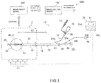
- FIG. 1 is a diagram showing an example of a configuration including an image analysis system comprising an image analysis device 100 according to an embodiment and a balloon catheter system 10 appli ed to balloon catheter treatment.
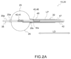
- FIG. 2A is a diagram showing an exa mple of a configuration in the vicinity of a balloon of a balloon catheter i n an inflated state.
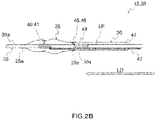
- FIG. 2B is a diagram showing an example of a confi guration in the vicinity of a balloon of a balloon catheter in a deflated st ate.
- a balloon catheter system 10 shown in FIG. 1 has a balloon catheter 15, a control unit 70 connected to the balloon catheter 15, and an agitator 75 connected to the balloon catheter 15.
- the balloon catheter 15 also has a catheter body 20 having a longitudinal direction LD, and a handle 50 connected to a proximal end of the catheter body 20.
- the catheter body 20 has a balloon 25, an outer cylinder shaft 30 connected to a proximal end 25b of the balloon 25, an inner cylinder shaft 35 connected to a distal end 25a of the balloon 25, and a heating member 40 disposed in the balloon 25.
- the inner cylinder shaft 35 passes through the outer cylinder shaft 30 to extend into the balloon 25.
- a liquid delivery path LP in communication with the balloon 25 is formed between the outer cylinder shaft 30 and the inner cylinder shaft 35.
- the heating member 40 heats a liquid in the balloon 25.
- the longitudinal direction LD of the catheter body 20 is specified as a direction along which center axes of the outer cylinder shaft 30 and the inner cylinder shaft 35 extending from the outer cylinder shaft 30 extend.
- distal side used for respective components of the balloon catheter 15 and the catheter body 20 means a side distant from an operator (surgeon) of the handle 50 and the balloon catheter 15 along the longitudinal direction LD of the catheter body 20, in other words, a distant side.
- proximal side used for respective components of the balloon catheter 15 and the catheter body 20 means a side close to the operator (surgeon) of the handle 50 and the balloon catheter 15 along the longitudinal direction LD of the catheter body 20, in other words, a near side.
- the catheter body 20 of the balloon catheter 15 is described in detail.
- the catheter body 20 of the balloon catheter 15 according to this embodiment has the balloon 25, the outer cylinder shaft 30, the inner cylinder shaft 35, the heating member 40, and the temperature sensor 45.
- the outer cylinder shaft 30 and the inner cylinder shaft 35 both have a tubular shape, typically a cylindrical shape.
- the outer cylinder shaft 30 and the inner cylinder shaft 35 respectively form lumens as inside spaces.
- a not-shown guide wire for example, is inserted thorough the lumen formed by the inner cylinder shaft 35.
- the inner cylinder shaft 35 is inserted through the lumen formed by the outer cylinder shaft 30.
- the outer cylinder shaft 30 and the inner cylinder shaft 35 form a dual shaft structure.
- An internal diameter of the outer cylinder shaft 30 is larger than an external diameter of the inner cylinder shaft 35.
- a lumen remains between the outer cylinder shaft 30 and the inner cylinder shaft 35.
- the balloon 25 is connected to the outer cylinder shaft 30 and the inner cylinder shaft 35.
- the balloon 25 is formed so as to be inflatable when it is filled with liquid and deflatable when a liquid is discharged therefrom.
- the balloon 25 is preferably shaped to fit a target site to be treated (e.g., blood vessel).
- the balloon 25 adapted for a pulmonary venous junction of a left atrium may have a spherical shape having a diameter between 15 mm or more and 40 mm or less.
- the spherical shape here includes a true spherical shape, a prolate shape, and a prolate spheroid shape. It also includes a substantially spherical shape.
- the distal end (distant end) 25a of the balloon 25 is fixed to a distal end (distant end) 35a of the inner cylinder shaft 35.
- the proximal end (near end) 25b of the balloon 25 is fixed to a distal end (distant end) 30a of the outer cylinder shaft 30.
- the balloon 25 is connected to the outer cylinder shaft 30 and the inner cylinder shaft 35 by adhesion or heat welding.
- the balloon 25 connected to the outer cylinder shaft 30 and the inner cylinder shaft 35 deforms.
- the relative movement of the outer cylinder shaft 30 and the inner cylinder shaft 35 allows a dimension of the balloon 25 to be adjusted in the longitudinal direction LD.
- FIG. 2B when the inner cylinder shaft 35 is relatively moved with respect to the outer cylinder shaft 30 to the distal side in the longitudinal direction LD, the balloon 25 is stretched in the longitudinal direction LD and is further strained.
- the movement range of the inner cylinder shaft 35 with respect to the outer cylinder shaft 30 to the distal side in the longitudinal direction is restricted by the balloon 25.
- the balloon 25 becomes loosened.
- the balloon 25 can be inflated. Namely, the relative movement of the outer cylinder shaft 30 and the inner cylinder shaft 35 allows for the dimension of the balloon 25 to be adjusted in the longitudinal direction LD.
- the heating member 40 is disposed in the balloon 25.
- the heating member 40 is a member for heating a liquid filled in the balloon 25.
- a nichrome wire that generates electric resistance heat can be employed as the heating member 40.
- a coil electrode 41 may be employed as another example of the heating member 40, as shown in Fig. 2A and FIG. 2B .
- high-frequency current conduction high-frequency energization
- a high-frequency current flows between the coil electrode 41 and a counter electrode 77 ( Fig. 1 ) disposed outside, so that the liquid positioned between the coil electrode 41 and the counter electrode 77 generates Joule heat.
- the counter electrode 77 is located on the back of a patient, for example.
- the coil electrode 41 is provided on the inner cylinder shaft 35 extending inside the balloon 25.
- the coil electrode 41 may be made by a conductive wire wound around the inner cylinder shaft 35.
- the coil electrode 41 is electrically connected to a wiring 42 for high-frequency current conduction.
- the wiring 42 extends in the liquid delivery path LP, which serves as a lumen between the outer cylinder shaft 30 and the inner cylinder shaft 35, up to the handle 50.
- the temperature sensor 45 acquires information on a liquid temperature.
- the temperature sensor 45 has a thermosensitive part 46 disposed in the liquid delivery path LP positioned between the outer cylinder shaft 30 and the inner cylinder shaft 35.
- the temperature sensor 45 typically has the thermosensitive part 46, and a lead wire 47 electrically connected to the thermosensitive part 46.
- the temperature sensor 45 comprises a thermocouple
- a part where different metals are connected serves as the thermosensitive part 46.
- the temperature sensor 45 comprises a thermistor
- a ceramic element serves as the thermosensitive part 46.
- the lead wire 47 extends inside the liquid delivery path LP, which serves as a lumen between the outer cylinder shaft 30 and the inner cylinder shaft 35, up to the handle 50.
- the temperature sensor 45 is attached to the inner cylinder shaft 35. As shown in FIG. 2A and FIG. 2B , the temperature sensor 45 is attached to the inner cylinder shaft 35 by fixing the lead wire 47 of the temperature sensor 45.
- the thermosensitive part 46 is apart from both the outer cylinder shaft 30 and the inner cylinder shaft 35.
- the handle 50 is a part grasped by an operator (surgeon) during the use of the balloon catheter system 10.
- the handle 50 shown in Fig. 1 has a first handle part 51 and a second handle part 52 that are slidable to each other.
- the first handle part (front handle part) 51 is connected to the outer cylinder shaft 30 of the catheter body 20.
- the second handle part (rear handle part) 52 is connected to the inner cylinder shaft 35 of the catheter body 20. By relatively moving the second handle part 52 with respect to the first handle part 51, the inner cylinder shaft 35 can be relatively moved with respect to the outer cylinder shaft 30.
- the handle 50 also functions as a part that connects other devices included in the balloon catheter system 10 and the balloon catheter 15.
- a connector 56 extends from the second handle part 52. This connector 56 electrically connects the wiring 42 of the catheter body 20 and the lead wire 47 of the temperature sensor 45 to the external control unit 70. The connector 56 extends from one of the branches 52a provided on the second handle part 52.
- the second handle part 52 has branches 52b and 52c other than the branch 52a to which the connector 56 is connected. These branches 52b and 52c function as a part through which a liquid is supplied to the lumen as an inside space of the inner cylinder shaft 35, and a part from which a guide wire inserted through the lumen of the inner cylinder shaft 35 extends.
- a saline solution an amount of which is as small as about 100 ml/hour is generally injected into a body through the lumen of the inner cylinder shaft 35. The injection of saline solution effectively prevents backflow of blood into the lumen of the inner cylinder shaft 35.
- an extension tube 57 extends from the first handle part 51.
- the extension tube 57 communicates the liquid delivery path LP of the catheter body 20 with an external supply unit 74 and the agitator 75.
- the extension tube 57 extends from the branch 51a provided on the first handle part 51.
- the extension tube 57 is connected to the supply unit 74 and the agitator 75 through a valve 58.
- whether the supply unit 74 or the agitator 75 is communicated with the liquid delivery path LP can be selected by operating the valve 58.
- a three-way stopper cock may be used as the valve 58.
- the illustrated control unit 70 is electrically connected to the coil electrode 41 through the wiring 42.
- the control unit 70 has a high-frequency current conduction controller 70A that controls high-frequency current conduction to the coil electrode 41.
- the high-frequency current conduction controller 70A controls the high-frequency current conduction to/through the coil electrode 41 to adjust an output from the heating member 40.
- the high-frequency current conduction controller 70A can control the high-frequency current conduction to the coil electrode 41 based on a surface temperature of the balloon 25 determined by a temperature computing unit 70B described later, or in accordance with a preset process, or in accordance with an input from an operator.
- control unit 70 is electrically connected to the lead wire 47 of the temperature sensor 45.
- the control unit 70 has the temperature computing unit 70B that computes information on a temperature acquired by the inner cylinder shaft 35.
- the temperature computing unit 70B calculates a liquid temperature in the liquid delivery path LP based on information on a temperature acquired by the temperature sensor 45, and further estimates a surface temperature of the balloon 25 based on the calculated liquid temperature.
- the temperature computing unit 70B may display a determined surface temperature of the balloon 25 on a display 71.
- the control unit 70 further has an agitator controller 70C that controls the agitator 75.
- the agitator controller 70C may display a control condition of the agitator 75 on the display 71.
- the supply unit 74 supplies a liquid into the liquid delivery path LP.
- the balloon 25 By supplying a liquid from the supply unit 74 to the balloon 25 through the liquid delivery path LP, the balloon 25 can be inflated as shown in FIG. 2A .
- the balloon 25 by discharging the liquid from the supply unit 74 from the balloon 25 through the liquid delivery path LP, the balloon 25 can be deflated.
- the liquid to be supplied into the liquid delivery path LP may typically be a saline solution.
- a syringe can be used as the supply unit 74 as illustrated. However, a pump or the like can also be used as the supply unit 74.
- the agitator 75 is provided for agitating a liquid in the balloon 25.
- heat supplied into the balloon 25 can be distributed or equalized so that a surface temperature of the balloon 25 can be adjusted.
- the agitator 75 repeats supply of supply of liquid to the liquid delivery path LP and discharge of liquid from the liquid delivery path LP.
- the image analysis system 1000 that outputs evaluation information for use in balloon catheter treatment for a subject will be descri bed.
- the image analysis system 1000 includes an image pickup device 200 configured to acquire captured image data of a two-dimensional captured image, and the image analysis device 100 configured to output evaluation information for use in balloon catheter treatment for a subject.
- the image pickup device 200 is adapted to take an image of the balloon catheter that has been inserted into the organ of the subject (the pulmonary vein of the left atrium of the heart) and pressed against the inner surface of the organ (for example, the myocardium), according to the operation of the operator, for example.
- the image pickup device 200 is adapted to take an image using X-rays. That is, in the present embodiment, the captured image is a two-dimensional X-ray fluoroscopic image obtained by seeing through a balloon catheter located in the organ of the subject using X-rays.
- the image analysis device 100 is adapted to output evaluation information for use in balloon catheter treatment for a subject based on the captured image data of the two-dimensional captured image acquired by the image pickup device 200, for example, depending on the operation of the operator.
- the image analysis device 100 may be configured by being integrally combined with the control device 70 described above, for example.
- FIG. 3 is a diagram showing an example of the configuration of the image analysis device 100 shown in FIG. 1 .
- the image analysis device 100 comprises, for example, an input unit IN, a processing unit Y, an output unit D, and a storage unit M, as shown in FIG.3 .
- the input unit IN is adapted to input the captured image data of the two-dimensional captured image obtained by imaging the balloon catheter in a state of being inserted into the organ of the subject and pressed against the inner surface of the organ.
- the processing unit Y acquires the evaluation image data of the two-dimensional evaluation image, by executing image processing on the captured image based on the captured image data input by the input unit IN. Then, the processing unit Y acquires evaluation information regarding the state of the balloon catheter pressed against the inner surface (myocardium) of the organ of the subject, based on the acquired evaluation image data. In particular, in image processing, the processing unit Y acquires the evaluation information including the measured value obtained by measuring the shape of the balloon catheter included in the captured image or the index calculated based on the measured value.
- This processing unit Y is composed of hardware such as a CPU, for example. At least a part of the processing unit Y may be configured by a software. Furthermore, in the processing unit Y, a part of the components of the processing unit Y may be able to cooperate with the above-mentioned control device 70 by communication through a network.
- the output unit D outputs the evaluation information acquired by the processing unit Y.
- the output unit D is, for example, a display device that displays the evaluation information to the outside.
- the storage unit M is designed to store captured image data, evaluation image data, and / or evaluation information.
- the storage unit M is, for example, a non-volatile memory such as a NAND flash memory.
- FIG. 4 is a diagram showing an example of a control method of the image analysis device 100 shown in FIG.3 .
- FIG. 5A is a diagram showing an example of image processing that executes a Sobel filter process and a Ring filter process for detecting a balloon in a captured image.
- FIG. 5B is a diagram showing an example of image processing for executing a process of detecting the edge of a balloon by performing a shading calculation on radiation from the center point of the balloon detected by the process of FIG. 5A .
- FIG. 5C is a diagram showing an example of image processing for executing a rectangular detection filter process for detecting an end portion and a tip tube of a sheath in a captured image.
- FIG. 5A is a diagram showing an example of image processing that executes a Sobel filter process and a Ring filter process for detecting a balloon in a captured image.
- FIG. 5B is a diagram showing an example of image processing for executing a process of detecting the edge of a balloon by performing a
- FIG. 5D is a diagram showing an example of image processing for calculating the angle difference between the end portion of the sheath and the tip tube in a captured image.
- FIG. 6 is a diagram showing an example of a model of rectangular detection filtering processing shown in FIG. 5C .
- the image pickup device 200 acquires the captured image data of the two-dimensional captured image, by imaging the balloon catheter that is inserted into the organ of the subject during the procedure and pressed against the inner surface (the myocardium) of the organ, for example, in response to the operation of the operator.
- the input unit IN of the image analysis device 100 inputs the captured image data of the two-dimensional captured image, output from the image pickup device 200, obtained by imaging the balloon catheter which is inserted into the organ of the subject during the procedure and pressed against the inner surface (the myocardium) of the organ (the step S1 in FIG. 4 ).
- the processing unit Y executes noise reduction processing, shading detection processing, or pattern matching processing on the captured image input by the input unit IN.
- the processing unit Y detects the balloon B of the balloon catheter from the captured image (the step S2 in FIG. 4 ).
- the balloon catheter includes: the tip tube A; the sheath C (corresponding to the outer cylinder shaft 30 shown in FIGS. 1 and 2A and B2 described above); the catheter tube housed in the sheath C (corresponding to the inner cylinder shaft 35 shown in FIGS. 1 and 2A and 2B described above); the balloon B having one end (the proximal end 25b of the balloon 25 shown in FIG. 2B described above) B1 connected to the end portion of the sheath C (corresponding to the balloon 25 shown in FIGS.
- the processing unit Y detects the balloon B from the captured image by executing the Sobel filter processing and the Ring filter processing on the captured image.
- the processing unit Y may detect the balloon B by executing only one of the Sobel filter processing and the Ring filter processing on the captured image.
- the processing unit Y acquires the shape of the balloon B in the captured image by detecting the edge of the balloon B of the balloon catheter (the step S3 in FIG. 4 ).
- the shading calculation is performed radially (for example, 2 ° interval) from the center of the balloon B detected by the process of FIG. 5A , the luminance change point is measured, and the edge BE is plotted.
- the processing unit Y detects the end portion of the sheath C and the tip tube A (the step S4 in FIG. 4 ).
- the processing unit Y detects the end portion of the sheath C and the tip tube A by the first and second rectangular detection filters F1 and F2, from the vicinity of one end B1 or the other end B2 (edge BE) of the balloon B detected from the captured image. More specifically, for example, as shown in FIG.
- the processing unit Y detects the one having the closest shape to the rectangular detection filter as the end portion of the sheath C or the tip tube A, by rotating the first and second rectangular detection filters F1 and F2 by 0 ° to 180 ° (for example, 2 ° interval) around the detected edge BE (including one end B1 and the other end B2) of the balloon B.
- the size of the first rectangular detection filter F1 for detecting the end of the sheath C is set to be different from the size of the second rectangular detection filter F2 for detecting the tip tube A, and the sizes of the first and second rectangular detection filters F1 and F2 are set so as not to interfere with other cables, wires, or the like.
- the wires and the like constituting the balloon catheter may be detected in order to evaluate the coaxiality, but the wires and the like may not be distinguishable from other wirings and the like. Therefore, by targeting the sheath C and the tip tube A, which are unique configurations of the balloon catheter, with the first and second rectangular detection filters F1 and F2, the sheath C and the tip tube A can be detected more accurately.
- the processing unit Y detects the balloon B located in the organ of the subject, the end of the sheath C (or the end of the catheter tube) in contact with one end B1 of the balloon B, and the tip tube A in contact with the other end B2 of the balloon B, from the captured image ( FIGS. 5C and 6 ).
- the processing unit Y evaluates the coaxiality of the balloon catheter in the pressed state (the step S5 in FIG. 4 ). For example, as shown in FIG. 5D , the processing unit Y acquires (calculates) the coaxiality indicating the relationship between the first axial direction T1, which is the direction of the end of the sheath C or the central axis of the catheter tube, and the second axial direction T2, which is the direction of the central axis of the tip tube A, detected from the image-processed captured image, as evaluation information.
- the processing unit Y calculates a first angle ⁇ 1 of the first axial direction (the long side direction of the end of the rectangular sheath C) T1 of the end portion of the sheath C with respect to the reference direction T and a second angle ⁇ 2 of the second axial direction (the long side direction of rectangular tip tube A) T2 of the tip tube A with respect to the reference direction T, in the two-dimensional captured image. Then, the processing unit Y acquires (calculates) the angle difference ⁇ d (the coaxiality), which is the difference between the first angle ⁇ 1 and the second angle ⁇ 2, as the evaluation information of the coaxiality.
- the angle difference ⁇ d the coaxiality
- the processing unit Y evaluates a state in which the end portion of the sheath C and the tip tube A are aligned with the balloon B (there is little difference in angle between the end of the sheath C and the tip tube A) as having high coaxiality.
- the processing unit Y may evaluate the change in the coaxiality of the balloon catheter within a predetermined period during the balloon catheter treatment, by performing the analysis of the moving image based on the captured image input from the input unit IN during the balloon catheter treatment.
- the processing unit Y evaluates the shape of the balloon catheter in the pressed state (the step S6 in FIG. 4 ).
- the processing unit Y may evaluate the change in the shape of the balloon B of the balloon catheter within a predetermined period during the treatment of the balloon catheter, by performing the analysis of the moving image based on the captured image input from the input unit IN during the balloon catheter treatment.
- the output unit D outputs the evaluation information acquired by the processing unit Y (the step S7 in FIG. 4 ).
- the output unit D displays, for example, the character information of the shape variation and the coaxiality, and the evaluation image including notations of the shape of the balloon B shown in FIG. 5D , the reference direction T, the first angle ⁇ 1, the first axial direction T1, the second angle ⁇ 2, the second axial direction T2, and the angle difference ⁇ d, as the evaluation information.
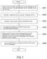
- FIG. 7 is a diagram showing a detailed example of a step of evaluating a shape in the control flow shown in FIG. 4 .
- FIG. 8A is a diagram showing an example of a two-dimensional image of a balloon catheter in a state of being pressed against the inner surface (the myocardium) of an organ of a subject, which is acquired in image processing.
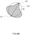
- FIG. 8B is a diagram showing an example in which a two-dimensional image of the balloon shown in FIG. 8A and the theoretical outer shape of the balloon before pressing are superimposed.
- FIG. 8C is a diagram showing an example of a model in which the theoretical balloon shape before pressing shown in FIG. 8B is divided into a plurality of regions along a line segment connecting one end and the other end.
- FIG. 8D is a diagram showing an example of a model in which the theoretical balloon shape before pressing shown in FIG. 8B is divided into a plurality of regions along a line segment connecting one end and the other end.
- the processing unit Y detects the first contact point (ie, one end of the balloon B) B1 between the detected edge of balloon B and the end of sheath C, and the second contact point (that is, the other end of the balloon B) B2 between the detected edge of the balloon B and the tip tube A (the step S61 in FIG. 7 , FIG. 8A ).
- the processing unit Y calculates the length of the line segment BL connecting the detected first contact point B1 and the second contact point B2, as the diameter value (the diameter (when the shape of balloon B in the captured image is circular), as the major axis (when the shape of balloon B in the captured image is elliptical), or as the minor axis (when the shape of balloon B in the captured image is elliptical)) of the balloon B in a free state (before being pressed) that is not pressed against the inner surface of the organ before the procedure (the step S62 in FIG. 7 ).
- the diameter value the diameter (when the shape of balloon B in the captured image is circular)
- the major axis when the shape of balloon B in the captured image is elliptical
- minor axis when the shape of balloon B in the captured image is elliptical
- the processing unit Y calculates the first balloon area of the first shape of the balloon B whose edge is detected in the pressed state in which the balloon B is pressed against the inner surface of the organ during the procedure (the step S63 in FIG. 7 ).
- the processing unit Y acquires (calculates) the theoretical second shape, which is the circle or ellipse, of the balloon B in a free state (before being pressed) that is not pressed against the inner surface of the organ before the procedure, based on the calculated diameter, major axis, or minor axis of balloon B, and the first balloon area (the step S64 in FIG. 7 , FIG. 8B ).
- the processing unit Y divides the first shape of the balloon B in the pressed state into a plurality of regions X1 to X6, and calculates the area of each region X1 to X6 of the divided first shape (the step S65 in FIG. 7 , and FIG. 8C ). For example, the processing unit Y divides the first shape of the balloon B in the pressed state into a plurality of regions along the line segment BL. Furthermore, the processing unit Y divides the first shape of the balloon B in the pressed state into a plurality of regions around the line segment BL. In particular, in this embodiment, for example, as shown in FIG.
- the processing unit Y divides the first shape into sections of each 1/3 of the length of the line segment BL along the line segment BL, and divides the first shape around the line segment BL, so that the processing unit Y divides the first shape of the balloon B in the pressed state into six regions X1 to X6.
- the processing unit Y divides the theoretical second shape of the balloon B into a plurality of regions X1 to X6 in the same manner as in dividing the first shape, and calculates the area of each region X1 to X6 of the divided second shape (the step S65, FIG. 8D ).
- the processing unit Y divides the theoretical second shape of the balloon B into a plurality of regions along the line segment BL.
- the processing unit Y divides the theoretical second shape of the balloon B into a plurality of regions around the line segment BL.
- the theoretical second shape of the balloon B is divided into six regions X1 to X6.
- the processing unit Y divides the second shape into sections of every 1/3 of the length of the line segment BL along the line segment BL, and divides the second shape around the line segment BL.
- the processing unit Y acquires the number of first pixels, which is the total number of pixels of the captured image corresponding to each region X1 to X6 of the detected first shape of the balloon B. Furthermore, the processing unit Y acquires the number of second pixels, which is the total number of pixels of the captured image corresponding to each region X1 to X6 of theoretical second shape of a free-state balloon B that is not pressed against the inner surface of the pre-procedural organ (before being pressed). By acquiring the number of the first and second pixels, the area corresponding to each region X1 to X6 can be acquired.
- the processing unit Y calculates the rate of change in the shape of the balloon B due to pressing against the inner surface of the organ (the step S66), by comparing the area of each region X1 to X6 of the first shape of the balloon B ( FIG. 8C ) and the area of each region X1 to X6 of the second shape of the balloon B ( FIG. 8D ), for each area X1 to X6 corresponding to the position in the captured image.
- the processing unit Y can evaluate the shape (obtain the rate of change in the shape) of the balloon B pressed against the inner surface of the organ during the procedure, for example, based on the difference between the number of first pixels (that is, the area) and the number of the second pixels (that is, the area) in each of the regions X1 to X6 acquired in the step S65 described above.
- FIG. 9 is a diagram showing an example of evaluation information displayed by the display unit D when the output unit D shown in FIG. 2 is a display device.
- the output unit (the display device) D may further display the captured image G1 together with the evaluation image G2 obtained by the image processing and the character information A regarding the rate of change in shape and the coaxiality.
- the notation of the reference direction T, the first angle ⁇ 1, the first axial direction T1, the second angle ⁇ 2, the second axial direction T2, and the angle difference ⁇ d described above is omitted.
- the notation of the reference direction T, the first angle ⁇ 1, the first axial direction T1, the second angle ⁇ 2, the second axial direction T2, and the angle difference ⁇ d may be displayed.
- the image analysis device 100 can output evaluation information for use in balloon catheter treatment for a subject in real time during the procedure using the balloon catheter.
- the doctor who is the operator can improve the success rate of the treatment in the balloon catheter treatment for the subject (human), by properly determining whether the surface temperature of the balloon is correctly transmitted to the myocardium, using the evaluation information output in real time from the image analysis device 100, the contact state between the balloon and the myocardium is recognized, during the procedure with the balloon catheter.
- the present invention can be used for a balloon catheter system and a balloon catheter for treating arrhythmia such as atrial fibrillation, endometriosis, cancer and the like.
Landscapes
- Health & Medical Sciences (AREA)
- Engineering & Computer Science (AREA)
- Life Sciences & Earth Sciences (AREA)
- Surgery (AREA)
- Nuclear Medicine, Radiotherapy & Molecular Imaging (AREA)
- Heart & Thoracic Surgery (AREA)
- General Health & Medical Sciences (AREA)
- Physics & Mathematics (AREA)
- Medical Informatics (AREA)
- Animal Behavior & Ethology (AREA)
- Public Health (AREA)
- Veterinary Medicine (AREA)
- Biomedical Technology (AREA)
- Molecular Biology (AREA)
- Radiology & Medical Imaging (AREA)
- Otolaryngology (AREA)
- Plasma & Fusion (AREA)
- Computer Vision & Pattern Recognition (AREA)
- Theoretical Computer Science (AREA)
- General Physics & Mathematics (AREA)
- Pathology (AREA)
- Cardiology (AREA)
- Gynecology & Obstetrics (AREA)
- Oral & Maxillofacial Surgery (AREA)
- Biophysics (AREA)
- Pulmonology (AREA)
- Anesthesiology (AREA)
- Hematology (AREA)
- Child & Adolescent Psychology (AREA)
- Geometry (AREA)
- Quality & Reliability (AREA)
- Media Introduction/Drainage Providing Device (AREA)
- High Energy & Nuclear Physics (AREA)
- Optics & Photonics (AREA)
- Apparatus For Radiation Diagnosis (AREA)
Abstract
Description
- The present invention relates to an image analysis device, a contr ol method for an image analysis device, an image analysis system, and a control method for an image analysis system.
- Conventionally, by inserting a catheter into an organ such as a blood vessel, an examination or treatment is performed on a lesion.
- For example, a support system has been proposed in which the contact state between the catheter and the myocardium is investigated in advance to convert it into data, and the result is displayed on the screen while performing the procedure (see, for example,
Patent Documents 1 and 2). - Furthermore, a system for determining and displaying the catheter position during ablation in real time has been proposed (see, for example, Patent Document 3).
-
- [Patent Document 1]
JP2017-148142 - [Patent Document 2]
JP2017-94073 - [Patent Document 3]
JP2019-103809 - Here, ablation with a balloon catheter in balloon catheter treatment is a procedure in which heat is transferred to the entire contact portion by ablation while contacting and pressing the balloon against the myocardium to treat multiple points at once. For example, the Satake Hot Balloon (Registered Trademark) applied to this balloon catheter treatment is to control the temperature by a coil electrode in the balloon and a thermocouple welded to the portion thereof.
- The inventor of this application has confirmed that, in such a Satake Hot Balloon (Registered Trademark), if the positional relationship of the balloon operation part (the sheath end and the tip tube) changes during the ablation, the surface temperature of the balloon will change. In addition, in this Satake Hot Balloon (Registered Trademark), a device that makes it easier to determine during the procedure whether the temperature of the balloon is correctly transmitted to the myocardium is requested by the doctor.
- Thus, the evaluation of the coaxiality, between the end of the sheath and the tip tube, which indicates that the controlled temperature of the balloon and the surface temperature of the actual balloon are in the same state, and the evaluation of the shape, which indicates that the balloon is in contact with the ablation point, are important for an effective procedure using a balloon catheter.
- Therefore, in the present invention, the coaxiality of the catheter is evaluated, by performing image processing on the fluoroscopic image used by the doctor during the procedure, from the detection of the end of the sheath and the tip tube. Then, the size of the balloon before being pressed against the myocardium is estimated from the number of pixels of the balloon detected on the fluoroscopic image. The amount of balloon deformation before and after the procedure is quantified by comparing it with the balloon size calculated from the input image. An image analysis device has been developed that can output an index during ablation treatment by processing and displaying this information in real time.
- As described above, an object of the present invention is to provide an image analysis device capable of outputting evaluation information for use in the balloon catheter treatment for subjects (e.g., humans), in real time during a procedure using a balloon catheter.
- The image analysis device according to the embodiment according to one aspect of the present invention includes: an input unit configured to input captured image data of a two-dimensional captured image of a balloon catheter inserted into an organ of the subject and pressed against an inner surface of the organ; a processing unit configured to obtain evaluation image data of a two-dimensional evaluation image, by executing an image processing on the captured image based on the captured image data input by the input unit, and configured to obtain evaluation information regarding a state of the balloon catheter pressed against the inner surface of the organ based on the evaluation image data; and an output unit configured to output the evaluation information acquired by the processing unit.
- In the image processing, the processing unit acquires the evaluati on information including the measured value obtained by measuring the shape of the balloon catheter included in the captured image or the inde x calculated based on the measured value, and the output unit outputs t he evaluation information acquired by the processing unit.
- In the image analysis device, wherein the output unit is a display device that displays the evaluation information to the outside.
- The captured image is a two-dimensional X-ray fluoroscopic image taken by seeing through the balloon catheter located in the organ of th e subject, using X-rays.
- In the image analysis device, wherein the balloon catheter compri ses: a sheath; a catheter tube housed in the sheath; a balloon having o ne end connected to an end of the sheath; and a tip tube connected to the other end of the balloon and configured to lead the sheath.
- In the image processing, the processing unit detects the balloon I ocated in the organ of the subject, the end of the sheath in contact with one end of the balloon or the end of the catheter tube, and tip tube in contact with the other end of the balloon, from the captured image, by e xecuting noise reduction processing, shading detection processing, or patt ern matching processing on the captured image input by the input unit.
- In the image processing, the processing unit detects the balloon f rom the captured image by executing the Sobel filter processing or the R ing filter processing on the captured image.
- In the image processing, the processing unit detects the end porti on of the sheath and the tip tube by a rectangular detection filter from a vicinity of the edge of the balloon detected from the captured image.
- In the image processing, a size of the first rectangular detection f ilter for detecting the end of the sheath is different from a size of the se cond rectangular detection filter for detecting the tip tube, and the size o f the first rectangular detection filter and the size of the second rectangu lar detection filter are set to sizes that do not interfere with a wire.
- In the image processing, the processing unit detects the coaxialit y indicating a relationship between a first axial direction, of the end of t he sheath or the catheter tube, and a second axial direction, of the tip t ube, from the image-processed captured image, and the processing unit acquires the detected coaxiality as the evaluation information.
- In the image processing, the processing unit calculates a first ang le in the first axial direction of the end of the sheath with respect to the reference direction and a second angle in the second axial direction of t he tip tube with respect to the reference direction, in the two-dimension al captured image, and the processing unit obtains an angle difference, which is the difference between the first angle and the second angle, as the evaluation information of the coaxiality.
- In the image processing, the processing unit obtains number of fi rst pixels, which is total number of pixels of the captured image correspo nding to a detected first shape of the balloon, and obtains number of se cond pixels, which is total number of pixels of the captured image corres ponding to a theoretical second shape of the balloon before being presse d against the inner surface of the organ, and the processing unit evaluat es the shape of the balloon pressed against the inner surface of the orga n based on a difference between the number of first pixels and the num ber of second pixels.
- In the image processing, the processing unit detects a first contac t point between the detected edge of the balloon and the end of the she ath, and a second contact point between the detected edge of the balloo n and the tip tube, the processing unit calculates a length of the line se gment connecting the first contact point and the second contact point de tected, as a diameter of the balloon before being pressed against the inn er surface of the organ, the processing unit calculates a first balloon are a of the first shape of the balloon whose edge is detected in a pressed s tate pressed against the inner surface of the organ, the processing unit obtains a theoretical second shape of a circle or ellipse of the balloon be fore the balloon is pressed against the inner surface of the organ, based on the calculated diameter of the balloon and the first balloon area, the processing unit divides the first shape of the balloon in the pressed state into a plurality of regions, the processing unit calculates area of each of the regions of the divided first shape, the processing unit divides the th eoretical second shape of the balloon into a plurality of regions in the sa me manner as the dividing of the first shape, the processing unit calcula tes the area of each region of the second shape divided, and the process ing unit calculates a rate of change in the shape of the balloon due to p ressing against the inner surface of the organ, by comparing the area of each region of the first shape of the balloon and the area of each region of the second shape of the balloon for each region corresponding to a p osition in the captured image.
- In the image processing, the processing unit divides the first shap e of the balloon in the pressed state into the plurality of regions along t he line segment, and the processing unit divides the theoretical second s hape of the balloon into the plurality of regions along the line segment.
- In the image processing, the processing unit divides the first shap e of the balloon in the pressed state into a plurality of regions around th e line segment, and divides the theoretical second shape of the balloon i nto a plurality of regions around the line segment.
- In the image processing, the processing unit divides the first shap e of the balloon in the pressed state into six regions, by dividing along t he line segment into sections every 1/3 of the length of the line segmen t and dividing by the center of the line segment, and the processing unit divides the theoretical second shape of the balloon into six regions, by dividing along the line segment into sections every 1/3 of the length of t he line segment and dividing by the center of the line segment.
- The image analysis device further includes a storage unit storing the evaluation information.
- In the image processing, the processing unit evaluates the change in the coaxiality of the balloon catheter within a predetermined period during the balloon catheter treatment, by performing the analysis of the moving image based on the captured image input from the input unit during the balloon catheter treatment.
- In image processing, the processing unit evaluates the change in the shape of the balloon of the balloon catheter within a predetermined period during the treatment of the balloon catheter, by performing the analysis of the moving image based on the captured image input from the input unit during the balloon catheter treatment.
- A control method, for an image analysis device, according to the embodiment according to one aspect of the present invention, the image analysis device comprises: an input unit configured to input captured image data of a two-dimensional captured image obtained by the image pickup device; a processing unit; and output unit, wherein the processing unit obtains evaluation image data of a two-dimensional evaluation image, by executing an image processing on the captured image based on the captured image data input by the input unit, and obtains evaluation information regarding a state of the balloon catheter pressed against the inner surface of the organ based on the evaluation image data, and wherein the output unit outputs the evaluation information acquired by the processing unit.
- An image analysis system, according to the embodiment accordin g to one aspect of the present invention, that outputs evaluation informa tion for use in balloon catheter treatment for subjects, the image analysi s system comprises: an image pickup device configured to obtain capture d image data of a two-dimensional captured image, by imaging a balloon catheter inserted into the organ of the subject and pressed against the inner surface of the organ; and an image analysis device configured to o utput evaluation information for use in balloon catheter treatment for the subject based on the captured image data of the captured image, wher ein the image analysis device comprises: an input unit configured to inpu t captured image data of a two-dimensional captured image obtained by the image pickup device; a processing unit configured to obtain evaluati on image data of a two-dimensional evaluation image, by executing an i mage processing on the captured image based on the captured image da ta input by the input unit, and configured to obtain evaluation informatio n regarding a state of the balloon catheter pressed against the inner surf ace of the organ based on the evaluation image data; and an output uni t configured to output the evaluation information acquired by the process ing unit.
- A control method, for an image analysis system, according to the embodiment according to one aspect of the present invention, the image analysis system outputs evaluation information for use in balloon cathete r treatment for subjects, the image analysis system comprises: an image pickup device configured to obtain captured image data of a two-dimens ional captured image, by imaging a balloon catheter inserted into the org an of the subject and pressed against the inner surface of the organ; an d an image analysis device configured to output evaluation information fo r use in balloon catheter treatment for the subject based on the capture d image data of the captured image, wherein the image analysis device comprises: an input unit configured to input captured image data of a tw o-dimensional captured image obtained by the image pickup device; a pr ocessing unit; and output unit, wherein the processing unit obtains evalu ation image data of a two-dimensional evaluation image, by executing an image processing on the captured image based on the captured image data input by the input unit, and obtains evaluation information regardin g a state of the balloon catheter pressed against the inner surface of the organ based on the evaluation image data, and wherein the output unit outputs the evaluation information acquired by the processing unit.
- An image analysis device according to one aspect of the present i nvention can output evaluation information for use in balloon catheter tre atment for subjects in real time during a procedure using a balloon cath eter.
-
- [
FIG. 1] FIG. 1 is a diagram showing an example of a configuration inclu ding an image analysis system comprising animage analysis device 100 according to an embodiment and aballoon catheter system 10 applied to balloon catheter treatment. - [
FIG. 2A] FIG. 2A is a diagram showing an example of a configuration in the vicinity of a balloon of a balloon catheter in an inflated state. - [
FIG. 2B] FIG. 2B is a diagram showing an example of a configuration in the vicinity of a balloon of a balloon catheter in a deflated state. - [
FIG. 3] FIG. 3 is a diagram showing an example of the configuration of theimage analysis device 100 shown inFIG.1 . - [
FIG. 4] FIG. 4 is a diagram showing an example of a control method of theimage analysis device 100 shown inFIG.3 . - [
FIG. 5A] FIG. 5A is a diagram showing an example of image processing that executes a Sobel filter process and a Ring filter process for detecting a balloon in a captured image. - [
FIG. 5B] FIG. 5B is a diagram showing an example of image processing for executing a process of detecting the edge of a balloon by performing a shading calculation on radiation from the center point of the balloon detected by the process ofFIG. 5A . - [
FIG. 5C] FIG. 5C is a diagram showing an example of image processing for executing a rectangular detection filter process for detecting an end portion and a tip tube of a sheath in a captured image. - [
FIG. 5D] FIG. 5D is a diagram showing an example of image processing for calculating the angle difference between the end portion of the sheath and the tip tube in a captured image. - [
FIG. 6] FIG. 6 is a diagram showing an example of a model of rectangular detection filtering processing shown inFIG. 5C . - [
FIG. 7] FIG. 7 is a diagram showing a detailed example of a step of evaluating a shape in the control flow shown inFIG. 4 . - [
FIG. 8A] FIG. 8A is a diagram showing an example of a two-dimensional image of a balloon catheter in a state of being pressed against the inner surface (the myocardium) of an organ of a subject, which is acquired in image processing. - [
FIG. 8B] FIG. 8B is a diagram showing an example in which a two-dimensional image of the balloon shown inFIG. 8A and the theoretical outer shape of the balloon before pressing are superimposed. - [
FIG. 8C] FIG. 8C is a diagram showing an example of a model in which the theoretical balloon shape before pressing shown inFIG. 8B is divided into a plurality of regions along a line segment connecting one end and the other end. - [
FIG. 8D] FIG. 8D is a diagram showing an example of a model in which the theoretical balloon shape before pressing shown inFIG. 8B is divided into a plurality of regions along a line segment connecting one end and the other end. - [
FIG. 9] FIG. 9 is a diagram showing an example of evaluation information displayed by the display unit when the output unit D shown inFIG. 3 is a display device. - An embodiment of the present invention will be described hereunder with reference to specific examples shown in the drawings. In the drawings attached to the specification, a scale dimension, an aspect ratio and so on are changed and exaggerated from the actual ones, for the convenience of easiness in illustration and understanding. In addition, terms used herein to specify shapes, geometric conditions and their degrees, e.g., "parallel", "orthogonal", "same", etc., and values of a length and an angle are not limited to their strict definitions, but construed to include a range capable of exerting a similar function, unless otherwise specified.
- In the embodiment shown below, as an example of a balloon catheter that is inserted into an organ of a subject (for example, human) and pressed against the inner surface of the organ, a balloon catheter applied to the balloon catheter treatment such as an arrhythmia of atrial fibrillation will be described. However, the balloon catheter can be used for a balloon catheter for treating other treatments such as endometriosis, cancer, etc.
- Here,
FIG. 1 is a diagram showing an example of a configuration including an image analysis system comprising animage analysis device 100 according to an embodiment and aballoon catheter system 10 appli ed to balloon catheter treatment.FIG. 2A is a diagram showing an exa mple of a configuration in the vicinity of a balloon of a balloon catheter i n an inflated state.FIG. 2B is a diagram showing an example of a confi guration in the vicinity of a balloon of a balloon catheter in a deflated st ate. - First, the
balloon catheter system 10 applied to the balloon catheter treatment for a subject will be described. - A
balloon catheter system 10 shown inFIG. 1 has aballoon catheter 15, acontrol unit 70 connected to theballoon catheter 15, and anagitator 75 connected to theballoon catheter 15. Theballoon catheter 15 also has acatheter body 20 having a longitudinal direction LD, and ahandle 50 connected to a proximal end of thecatheter body 20. - As shown in
FIG. 2A , thecatheter body 20 according to this embodiment has aballoon 25, anouter cylinder shaft 30 connected to aproximal end 25b of theballoon 25, aninner cylinder shaft 35 connected to adistal end 25a of theballoon 25, and a heating member 40 disposed in theballoon 25. Theinner cylinder shaft 35 passes through theouter cylinder shaft 30 to extend into theballoon 25. A liquid delivery path LP in communication with theballoon 25 is formed between theouter cylinder shaft 30 and theinner cylinder shaft 35. The heating member 40 heats a liquid in theballoon 25. - The longitudinal direction LD of the
catheter body 20 is specified as a direction along which center axes of theouter cylinder shaft 30 and theinner cylinder shaft 35 extending from theouter cylinder shaft 30 extend. In this specification, the term "distal" side used for respective components of theballoon catheter 15 and thecatheter body 20 means a side distant from an operator (surgeon) of thehandle 50 and theballoon catheter 15 along the longitudinal direction LD of thecatheter body 20, in other words, a distant side. In addition, the term "proximal" side used for respective components of theballoon catheter 15 and thecatheter body 20 means a side close to the operator (surgeon) of thehandle 50 and theballoon catheter 15 along the longitudinal direction LD of thecatheter body 20, in other words, a near side. - The
balloon catheter system 10 and theballoon catheter 15 are further described in detail hereunder. First, thecatheter body 20 of theballoon catheter 15 is described in detail. As described above, thecatheter body 20 of theballoon catheter 15 according to this embodiment has theballoon 25, theouter cylinder shaft 30, theinner cylinder shaft 35, the heating member 40, and the temperature sensor 45. - The
outer cylinder shaft 30 and theinner cylinder shaft 35 both have a tubular shape, typically a cylindrical shape. Thus, theouter cylinder shaft 30 and theinner cylinder shaft 35 respectively form lumens as inside spaces. A not-shown guide wire, for example, is inserted thorough the lumen formed by theinner cylinder shaft 35. Theinner cylinder shaft 35 is inserted through the lumen formed by theouter cylinder shaft 30. Namely, theouter cylinder shaft 30 and theinner cylinder shaft 35 form a dual shaft structure. An internal diameter of theouter cylinder shaft 30 is larger than an external diameter of theinner cylinder shaft 35. Thus, a lumen remains between theouter cylinder shaft 30 and theinner cylinder shaft 35. The lumen between theouter cylinder shaft 30 and theinner cylinder shaft 35 form the liquid delivery path LP. As shown inFIG. 2A , the liquid delivery path LP is in communion with theballoon 25. The liquid delivery path LP extends up to an inside of thehandle 50. - The
balloon 25 is connected to theouter cylinder shaft 30 and theinner cylinder shaft 35. Theballoon 25 is formed so as to be inflatable when it is filled with liquid and deflatable when a liquid is discharged therefrom. Theballoon 25 is preferably shaped to fit a target site to be treated (e.g., blood vessel). As an example, theballoon 25 adapted for a pulmonary venous junction of a left atrium may have a spherical shape having a diameter between 15 mm or more and 40 mm or less. The spherical shape here includes a true spherical shape, a prolate shape, and a prolate spheroid shape. It also includes a substantially spherical shape. - In the illustrated
catheter body 20, as shown inFIG. 2A andFIG. 2B , the distal end (distant end) 25a of theballoon 25 is fixed to a distal end (distant end) 35a of theinner cylinder shaft 35. The proximal end (near end) 25b of theballoon 25 is fixed to a distal end (distant end) 30a of theouter cylinder shaft 30. Theballoon 25 is connected to theouter cylinder shaft 30 and theinner cylinder shaft 35 by adhesion or heat welding. - By the relative movement of the
outer cylinder shaft 30 and theinner cylinder shaft 35 in the longitudinal direction LD, theballoon 25 connected to theouter cylinder shaft 30 and theinner cylinder shaft 35 deforms. In the illustrated example, the relative movement of theouter cylinder shaft 30 and theinner cylinder shaft 35 allows a dimension of theballoon 25 to be adjusted in the longitudinal direction LD. As shown inFIG. 2B , when theinner cylinder shaft 35 is relatively moved with respect to theouter cylinder shaft 30 to the distal side in the longitudinal direction LD, theballoon 25 is stretched in the longitudinal direction LD and is further strained. In the illustrated example, the movement range of theinner cylinder shaft 35 with respect to theouter cylinder shaft 30 to the distal side in the longitudinal direction is restricted by theballoon 25. When theinner cylinder shaft 35 is relatively moved with respect to theouter cylinder shaft 30 from the position shown inFIG. 2B to the proximal side in the longitudinal direction LD, theballoon 25 becomes loosened. By introducing a liquid into the loosenedballoon 25, as shown inFIG. 2A , theballoon 25 can be inflated. Namely, the relative movement of theouter cylinder shaft 30 and theinner cylinder shaft 35 allows for the dimension of theballoon 25 to be adjusted in the longitudinal direction LD. - The heating member 40 is disposed in the
balloon 25. The heating member 40 is a member for heating a liquid filled in theballoon 25. As an example, a nichrome wire that generates electric resistance heat can be employed as the heating member 40. A coil electrode 41 may be employed as another example of the heating member 40, as shown inFig. 2A andFIG. 2B . By means of high-frequency current conduction (high-frequency energization) to the heating member 40 as the coil electrode 41, a high-frequency current flows between the coil electrode 41 and a counter electrode 77 (Fig. 1 ) disposed outside, so that the liquid positioned between the coil electrode 41 and thecounter electrode 77 generates Joule heat. Thecounter electrode 77 is located on the back of a patient, for example. - In the example shown in
FIG. 2A andFIG. 2B , the coil electrode 41 is provided on theinner cylinder shaft 35 extending inside theballoon 25. The coil electrode 41 may be made by a conductive wire wound around theinner cylinder shaft 35. The coil electrode 41 is electrically connected to awiring 42 for high-frequency current conduction. Thewiring 42 extends in the liquid delivery path LP, which serves as a lumen between theouter cylinder shaft 30 and theinner cylinder shaft 35, up to thehandle 50. - The temperature sensor 45 acquires information on a liquid temperature. In this embodiment, the temperature sensor 45 has a thermosensitive part 46 disposed in the liquid delivery path LP positioned between the
outer cylinder shaft 30 and theinner cylinder shaft 35. - In order to highly precisely determine a surface temperature of the
balloon 25, there is a preferable length DX along the longitudinal direction LD of the outer cylinder shaft from thedistal end 30a of theouter cylinder shaft 30 up to the thermosensitive part 46 of the temperature sensor 45. - As shown in
FIG. 2A andFIG. 2B , the temperature sensor 45 typically has the thermosensitive part 46, and alead wire 47 electrically connected to the thermosensitive part 46. When the temperature sensor 45 comprises a thermocouple, a part where different metals are connected serves as the thermosensitive part 46. When the temperature sensor 45 comprises a thermistor, a ceramic element serves as the thermosensitive part 46. Thelead wire 47 extends inside the liquid delivery path LP, which serves as a lumen between theouter cylinder shaft 30 and theinner cylinder shaft 35, up to thehandle 50. - In the illustrated example, the temperature sensor 45 is attached to the
inner cylinder shaft 35. As shown inFIG. 2A andFIG. 2B , the temperature sensor 45 is attached to theinner cylinder shaft 35 by fixing thelead wire 47 of the temperature sensor 45. The thermosensitive part 46 is apart from both theouter cylinder shaft 30 and theinner cylinder shaft 35. - Next, the
handle 50 is a part grasped by an operator (surgeon) during the use of theballoon catheter system 10. - The
handle 50 shown inFig. 1 has afirst handle part 51 and asecond handle part 52 that are slidable to each other. The first handle part (front handle part) 51 is connected to theouter cylinder shaft 30 of thecatheter body 20. The second handle part (rear handle part) 52 is connected to theinner cylinder shaft 35 of thecatheter body 20. By relatively moving thesecond handle part 52 with respect to thefirst handle part 51, theinner cylinder shaft 35 can be relatively moved with respect to theouter cylinder shaft 30. - As shown in
Fig. 1 , thehandle 50 also functions as a part that connects other devices included in theballoon catheter system 10 and theballoon catheter 15. - A
connector 56 extends from thesecond handle part 52. Thisconnector 56 electrically connects thewiring 42 of thecatheter body 20 and thelead wire 47 of the temperature sensor 45 to theexternal control unit 70. Theconnector 56 extends from one of thebranches 52a provided on thesecond handle part 52. - The
second handle part 52 hasbranches branch 52a to which theconnector 56 is connected. Thesebranches inner cylinder shaft 35, and a part from which a guide wire inserted through the lumen of theinner cylinder shaft 35 extends. During a cardiac ablation therapy, a saline solution an amount of which is as small as about 100 ml/hour is generally injected into a body through the lumen of theinner cylinder shaft 35. The injection of saline solution effectively prevents backflow of blood into the lumen of theinner cylinder shaft 35. - In addition, as shown in
Fig. 1 , anextension tube 57 extends from thefirst handle part 51. Theextension tube 57 communicates the liquid delivery path LP of thecatheter body 20 with anexternal supply unit 74 and theagitator 75. Theextension tube 57 extends from thebranch 51a provided on thefirst handle part 51. Theextension tube 57 is connected to thesupply unit 74 and theagitator 75 through avalve 58. In the illustrated example, whether thesupply unit 74 or theagitator 75 is communicated with the liquid delivery path LP can be selected by operating thevalve 58. A three-way stopper cock may be used as thevalve 58. - Next, devices constituting the
balloon catheter system 10 together with theaforementioned balloon catheter 15, to be specific, thecontrol unit 70, thesupply unit 74 and theagitator 75, are described. - The illustrated
control unit 70 is electrically connected to the coil electrode 41 through thewiring 42. Thecontrol unit 70 has a high-frequencycurrent conduction controller 70A that controls high-frequency current conduction to the coil electrode 41. In the illustrated example, the high-frequencycurrent conduction controller 70A controls the high-frequency current conduction to/through the coil electrode 41 to adjust an output from the heating member 40. The high-frequencycurrent conduction controller 70A can control the high-frequency current conduction to the coil electrode 41 based on a surface temperature of theballoon 25 determined by atemperature computing unit 70B described later, or in accordance with a preset process, or in accordance with an input from an operator. - In addition, the
control unit 70 is electrically connected to thelead wire 47 of the temperature sensor 45. Thecontrol unit 70 has thetemperature computing unit 70B that computes information on a temperature acquired by theinner cylinder shaft 35. Thetemperature computing unit 70B calculates a liquid temperature in the liquid delivery path LP based on information on a temperature acquired by the temperature sensor 45, and further estimates a surface temperature of theballoon 25 based on the calculated liquid temperature. Thetemperature computing unit 70B may display a determined surface temperature of theballoon 25 on adisplay 71. - The
control unit 70 further has anagitator controller 70C that controls theagitator 75. Theagitator controller 70C may display a control condition of theagitator 75 on thedisplay 71. - Next, the
supply unit 74 supplies a liquid into the liquid delivery path LP. By supplying a liquid from thesupply unit 74 to theballoon 25 through the liquid delivery path LP, theballoon 25 can be inflated as shown inFIG. 2A . On the other hand, by discharging the liquid from thesupply unit 74 from theballoon 25 through the liquid delivery path LP, theballoon 25 can be deflated. The liquid to be supplied into the liquid delivery path LP may typically be a saline solution. A syringe can be used as thesupply unit 74 as illustrated. However, a pump or the like can also be used as thesupply unit 74. - Next, the
agitator 75 is provided for agitating a liquid in theballoon 25. By agitating the liquid in theballoon 25, heat supplied into theballoon 25 can be distributed or equalized so that a surface temperature of theballoon 25 can be adjusted. Theagitator 75 repeats supply of supply of liquid to the liquid delivery path LP and discharge of liquid from the liquid delivery path LP. - Next, the
image analysis system 1000 that outputs evaluation information for use in balloon catheter treatment for a subject will be descri bed. - For example, as shown in
FIG. 1 described above, theimage analysis system 1000 includes animage pickup device 200 configured to acquire captured image data of a two-dimensional captured image, and theimage analysis device 100 configured to output evaluation information for use in balloon catheter treatment for a subject. - Then, the
image pickup device 200 is adapted to take an image of the balloon catheter that has been inserted into the organ of the subject (the pulmonary vein of the left atrium of the heart) and pressed against the inner surface of the organ (for example, the myocardium), according to the operation of the operator, for example. Theimage pickup device 200 is adapted to take an image using X-rays. That is, in the present embodiment, the captured image is a two-dimensional X-ray fluoroscopic image obtained by seeing through a balloon catheter located in the organ of the subject using X-rays. - Also, for example, as shown in
FIG.1 , theimage analysis device 100 is adapted to output evaluation information for use in balloon catheter treatment for a subject based on the captured image data of the two-dimensional captured image acquired by theimage pickup device 200, for example, depending on the operation of the operator. - The
image analysis device 100 may be configured by being integrally combined with thecontrol device 70 described above, for example. - Here,
FIG. 3 is a diagram showing an example of the configuration of theimage analysis device 100 shown inFIG. 1 . Theimage analysis device 100 comprises, for example, an input unit IN, a processing unit Y, an output unit D, and a storage unit M, as shown inFIG.3 . - Then, the input unit IN is adapted to input the captured image data of the two-dimensional captured image obtained by imaging the balloon catheter in a state of being inserted into the organ of the subject and pressed against the inner surface of the organ.
- Furthermore, the processing unit Y acquires the evaluation image data of the two-dimensional evaluation image, by executing image processing on the captured image based on the captured image data input by the input unit IN. Then, the processing unit Y acquires evaluation information regarding the state of the balloon catheter pressed against the inner surface (myocardium) of the organ of the subject, based on the acquired evaluation image data. In particular, in image processing, the processing unit Y acquires the evaluation information including the measured value obtained by measuring the shape of the balloon catheter included in the captured image or the index calculated based on the measured value.
- This processing unit Y is composed of hardware such as a CPU, for example. At least a part of the processing unit Y may be configured by a software. Furthermore, in the processing unit Y, a part of the components of the processing unit Y may be able to cooperate with the above-mentioned
control device 70 by communication through a network. - Furthermore, the output unit D outputs the evaluation information acquired by the processing unit Y. The output unit D is, for example, a display device that displays the evaluation information to the outside.
- Furthermore, the storage unit M is designed to store captured image data, evaluation image data, and / or evaluation information. The storage unit M is, for example, a non-volatile memory such as a NAND flash memory.
- Next, a control method of the
image analysis device 100 having the above configuration will be described.FIG. 4 is a diagram showing an example of a control method of theimage analysis device 100 shown inFIG.3 .FIG. 5A is a diagram showing an example of image processing that executes a Sobel filter process and a Ring filter process for detecting a balloon in a captured image.FIG. 5B is a diagram showing an example of image processing for executing a process of detecting the edge of a balloon by performing a shading calculation on radiation from the center point of the balloon detected by the process ofFIG. 5A .FIG. 5C is a diagram showing an example of image processing for executing a rectangular detection filter process for detecting an end portion and a tip tube of a sheath in a captured image.FIG. 5D is a diagram showing an example of image processing for calculating the angle difference between the end portion of the sheath and the tip tube in a captured image.FIG. 6 is a diagram showing an example of a model of rectangular detection filtering processing shown inFIG. 5C . - First, the
image pickup device 200 acquires the captured image data of the two-dimensional captured image, by imaging the balloon catheter that is inserted into the organ of the subject during the procedure and pressed against the inner surface (the myocardium) of the organ, for example, in response to the operation of the operator. - Then, for example, as shown in
Fig. 4 , the input unit IN of theimage analysis device 100 inputs the captured image data of the two-dimensional captured image, output from theimage pickup device 200, obtained by imaging the balloon catheter which is inserted into the organ of the subject during the procedure and pressed against the inner surface (the myocardium) of the organ (the step S1 inFIG. 4 ). - Next, in the image processing, the processing unit Y executes noise reduction processing, shading detection processing, or pattern matching processing on the captured image input by the input unit IN.
- Then, in the image processing, the processing unit Y detects the balloon B of the balloon catheter from the captured image (the step S2 in
FIG. 4 ). - Here, in the image-processed captured image, for example, as shown in
FIG. 5A . it is assumed that the balloon catheter includes: the tip tube A; the sheath C (corresponding to theouter cylinder shaft 30 shown inFIGS. 1 and2A and B2 described above); the catheter tube housed in the sheath C (corresponding to theinner cylinder shaft 35 shown inFIGS. 1 and2A and 2B described above); the balloon B having one end (theproximal end 25b of theballoon 25 shown inFIG. 2B described above) B1 connected to the end portion of the sheath C (corresponding to theballoon 25 shown inFIGS. 1 and2A and2B described above); and the tip tube A (corresponds to the distal end (tip) 35a of the inner cylinder shaft 35) which is connected to the other end B2 (corresponding to thedistal end 25a of theballoon 25 inFIG. 2B ) of the balloon B, is continuous with the catheter tube, and leads the sheath C. In this case, for example, as shown inFIG. 5A , in the image processing, the processing unit Y detects the balloon B from the captured image by executing the Sobel filter processing and the Ring filter processing on the captured image. Here, the processing unit Y may detect the balloon B by executing only one of the Sobel filter processing and the Ring filter processing on the captured image. - Next, in the image processing, the processing unit Y acquires the shape of the balloon B in the captured image by detecting the edge of the balloon B of the balloon catheter (the step S3 in
FIG. 4 ). Here, for example, as shown inFIG. 5B , the shading calculation is performed radially (for example, 2 ° interval) from the center of the balloon B detected by the process ofFIG. 5A , the luminance change point is measured, and the edge BE is plotted. - Next, in image processing, the processing unit Y detects the end portion of the sheath C and the tip tube A (the step S4 in
FIG. 4 ). For example, as shown inFIG. 5C , in image processing, the processing unit Y detects the end portion of the sheath C and the tip tube A by the first and second rectangular detection filters F1 and F2, from the vicinity of one end B1 or the other end B2 (edge BE) of the balloon B detected from the captured image. More specifically, for example, as shown inFIG. 6 , the processing unit Y detects the one having the closest shape to the rectangular detection filter as the end portion of the sheath C or the tip tube A, by rotating the first and second rectangular detection filters F1 and F2 by 0 ° to 180 ° (for example, 2 ° interval) around the detected edge BE (including one end B1 and the other end B2) of the balloon B. - In image processing, for example, the size of the first rectangular detection filter F1 for detecting the end of the sheath C is set to be different from the size of the second rectangular detection filter F2 for detecting the tip tube A, and the sizes of the first and second rectangular detection filters F1 and F2 are set so as not to interfere with other cables, wires, or the like.
- Furthermore, in image processing, the wires and the like constituting the balloon catheter may be detected in order to evaluate the coaxiality, but the wires and the like may not be distinguishable from other wirings and the like. Therefore, by targeting the sheath C and the tip tube A, which are unique configurations of the balloon catheter, with the first and second rectangular detection filters F1 and F2, the sheath C and the tip tube A can be detected more accurately.
- In this way, the processing unit Y detects the balloon B located in the organ of the subject, the end of the sheath C (or the end of the catheter tube) in contact with one end B1 of the balloon B, and the tip tube A in contact with the other end B2 of the balloon B, from the captured image (
FIGS. 5C and6 ). - Next, in image processing, the processing unit Y evaluates the coaxiality of the balloon catheter in the pressed state (the step S5 in
FIG. 4 ). For example, as shown inFIG. 5D , the processing unit Y acquires (calculates) the coaxiality indicating the relationship between the first axial direction T1, which is the direction of the end of the sheath C or the central axis of the catheter tube, and the second axial direction T2, which is the direction of the central axis of the tip tube A, detected from the image-processed captured image, as evaluation information. - Specifically, in image processing, for example, as shown in
FIG. 5D , the processing unit Y calculates a first angle θ1 of the first axial direction (the long side direction of the end of the rectangular sheath C) T1 of the end portion of the sheath C with respect to the reference direction T and a second angle θ2 of the second axial direction (the long side direction of rectangular tip tube A) T2 of the tip tube A with respect to the reference direction T, in the two-dimensional captured image. Then, the processing unit Y acquires (calculates) the angle difference θd (the coaxiality), which is the difference between the first angle θ1 and the second angle θ2, as the evaluation information of the coaxiality. - For example, the processing unit Y evaluates a state in which the end portion of the sheath C and the tip tube A are aligned with the balloon B (there is little difference in angle between the end of the sheath C and the tip tube A) as having high coaxiality.
- Further, the processing unit Y may evaluate the change in the coaxiality of the balloon catheter within a predetermined period during the balloon catheter treatment, by performing the analysis of the moving image based on the captured image input from the input unit IN during the balloon catheter treatment.
- Next, in image processing, the processing unit Y evaluates the shape of the balloon catheter in the pressed state (the step S6 in
FIG. 4 ). The processing unit Y may evaluate the change in the shape of the balloon B of the balloon catheter within a predetermined period during the treatment of the balloon catheter, by performing the analysis of the moving image based on the captured image input from the input unit IN during the balloon catheter treatment. - Next, the output unit D outputs the evaluation information acquired by the processing unit Y (the step S7 in
FIG. 4 ). Here, the output unit D displays, for example, the character information of the shape variation and the coaxiality, and the evaluation image including notations of the shape of the balloon B shown inFIG. 5D , the reference direction T, the first angle θ1, the first axial direction T1, the second angle θ2, the second axial direction T2, and the angle difference θd, as the evaluation information. - Here,
FIG. 7 is a diagram showing a detailed example of a step of evaluating a shape in the control flow shown inFIG. 4 .FIG. 8A is a diagram showing an example of a two-dimensional image of a balloon catheter in a state of being pressed against the inner surface (the myocardium) of an organ of a subject, which is acquired in image processing.FIG. 8B is a diagram showing an example in which a two-dimensional image of the balloon shown inFIG. 8A and the theoretical outer shape of the balloon before pressing are superimposed.FIG. 8C is a diagram showing an example of a model in which the theoretical balloon shape before pressing shown inFIG. 8B is divided into a plurality of regions along a line segment connecting one end and the other end.FIG. 8D is a diagram showing an example of a model in which the theoretical balloon shape before pressing shown inFIG. 8B is divided into a plurality of regions along a line segment connecting one end and the other end. - In the step S6 for evaluating the shape of the balloon B in the state of being inserted into the organ of the subject and pressed against the inner surface K of the organ in the control flow shown in
FIG. 4 described above, in image processing, the processing unit Y detects the first contact point (ie, one end of the balloon B) B1 between the detected edge of balloon B and the end of sheath C, and the second contact point (that is, the other end of the balloon B) B2 between the detected edge of the balloon B and the tip tube A (the step S61 inFIG. 7 ,FIG. 8A ). - Next, the processing unit Y calculates the length of the line segment BL connecting the detected first contact point B1 and the second contact point B2, as the diameter value (the diameter (when the shape of balloon B in the captured image is circular), as the major axis (when the shape of balloon B in the captured image is elliptical), or as the minor axis (when the shape of balloon B in the captured image is elliptical)) of the balloon B in a free state (before being pressed) that is not pressed against the inner surface of the organ before the procedure (the step S62 in
FIG. 7 ). - Next, the processing unit Y calculates the first balloon area of the first shape of the balloon B whose edge is detected in the pressed state in which the balloon B is pressed against the inner surface of the organ during the procedure (the step S63 in
FIG. 7 ). - Next, the processing unit Y acquires (calculates) the theoretical second shape, which is the circle or ellipse, of the balloon B in a free state (before being pressed) that is not pressed against the inner surface of the organ before the procedure, based on the calculated diameter, major axis, or minor axis of balloon B, and the first balloon area (the step S64 in
FIG. 7 ,FIG. 8B ). - Next, the processing unit Y divides the first shape of the balloon B in the pressed state into a plurality of regions X1 to X6, and calculates the area of each region X1 to X6 of the divided first shape (the step S65 in
FIG. 7 , andFIG. 8C ). For example, the processing unit Y divides the first shape of the balloon B in the pressed state into a plurality of regions along the line segment BL. Furthermore, the processing unit Y divides the first shape of the balloon B in the pressed state into a plurality of regions around the line segment BL. In particular, in this embodiment, for example, as shown inFIG. 8C , the processing unit Y divides the first shape into sections of each 1/3 of the length of the line segment BL along the line segment BL, and divides the first shape around the line segment BL, so that the processing unit Y divides the first shape of the balloon B in the pressed state into six regions X1 to X6. - Furthermore, the processing unit Y divides the theoretical second shape of the balloon B into a plurality of regions X1 to X6 in the same manner as in dividing the first shape, and calculates the area of each region X1 to X6 of the divided second shape (the step S65,
FIG. 8D ). For example, the processing unit Y divides the theoretical second shape of the balloon B into a plurality of regions along the line segment BL. Furthermore, the processing unit Y divides the theoretical second shape of the balloon B into a plurality of regions around the line segment BL. In particular, in the present embodiment, the theoretical second shape of the balloon B is divided into six regions X1 to X6. For example, as shown inFIG. 8D , the processing unit Y divides the second shape into sections of every 1/3 of the length of the line segment BL along the line segment BL, and divides the second shape around the line segment BL. - Here, in this step S65, for example, in image processing, the processing unit Y acquires the number of first pixels, which is the total number of pixels of the captured image corresponding to each region X1 to X6 of the detected first shape of the balloon B. Furthermore, the processing unit Y acquires the number of second pixels, which is the total number of pixels of the captured image corresponding to each region X1 to X6 of theoretical second shape of a free-state balloon B that is not pressed against the inner surface of the pre-procedural organ (before being pressed). By acquiring the number of the first and second pixels, the area corresponding to each region X1 to X6 can be acquired.
- Next, the processing unit Y calculates the rate of change in the shape of the balloon B due to pressing against the inner surface of the organ (the step S66), by comparing the area of each region X1 to X6 of the first shape of the balloon B (
FIG. 8C ) and the area of each region X1 to X6 of the second shape of the balloon B (FIG. 8D ), for each area X1 to X6 corresponding to the position in the captured image. - In particular, in this step S66, the processing unit Y can evaluate the shape (obtain the rate of change in the shape) of the balloon B pressed against the inner surface of the organ during the procedure, for example, based on the difference between the number of first pixels (that is, the area) and the number of the second pixels (that is, the area) in each of the regions X1 to X6 acquired in the step S65 described above.
- In the calculation of the above area, it is assumed that the length (the diameter of the balloon B) of the line segment BL connecting the first contact point B1 and the second contact point B2 has not changed, by pressing the balloon B against the inner surface of the organ.
- Here,
FIG. 9 is a diagram showing an example of evaluation information displayed by the display unit D when the output unit D shown inFIG. 2 is a display device. - For example, as shown in
Fig. 9 , the output unit (the display device) D may further display the captured image G1 together with the evaluation image G2 obtained by the image processing and the character information A regarding the rate of change in shape and the coaxiality. - In the example shown in
Fig. 9 , the notation of the reference direction T, the first angle θ1, the first axial direction T1, the second angle θ2, the second axial direction T2, and the angle difference θd described above is omitted. However, for example, as shown inFIG. 5D , the notation of the reference direction T, the first angle θ1, the first axial direction T1, the second angle θ2, the second axial direction T2, and the angle difference θd may be displayed. - As described above, the
image analysis device 100 according to the present embodiment can output evaluation information for use in balloon catheter treatment for a subject in real time during the procedure using the balloon catheter. - Thereby, for example, the doctor who is the operator can improve the success rate of the treatment in the balloon catheter treatment for the subject (human), by properly determining whether the surface temperature of the balloon is correctly transmitted to the myocardium, using the evaluation information output in real time from the
image analysis device 100, the contact state between the balloon and the myocardium is recognized, during the procedure with the balloon catheter. - While certain embodiments have been described, these embodiments have been presented by way of example only, and are not intended to limit the scope of the inventions. The embodiments may be embodied in a variety of other forms. Furthermore, various omissions, substitutions and changes in the form of the methods and systems described herein may be made without departing from the spirit of the inventions. The embodiments and their modifications are included in the scope and the subject matter of the invention, and at the same time included in the scope of the claimed inventions and their equivalents.
- The present invention can be used for a balloon catheter system and a balloon catheter for treating arrhythmia such as atrial fibrillation, endometriosis, cancer and the like.
-
- 100
- image analysis device
- IN
- input unit
- Y
- processing unit
- D
- output unit
- M
- storage unit
Claims (15)
- An image analysis device that outputs evaluation information for use in a balloon catheter treatment for a subject, the image analysis dev ice comprising:an input unit configured to input captured image data of a two-di mensional captured image of a balloon catheter inserted into an organ of the subject and pressed against an inner surface of the organ;a processing unit configured to obtain evaluation image data of a two-dimensional evaluation image, by executing an image processing on the captured image based on the captured image data input by the input unit, and configured to obtain evaluation information regarding a state o f the balloon catheter pressed against the inner surface of the organ bas ed on the evaluation image data; andan output unit configured to output the evaluation information ac quired by the processing unit.
- The image analysis device according to claim 1,wherein, in the image processing,the processing unit acquires the evaluation information including t he measured value obtained by measuring the shape of the balloon cath eter included in the captured image or an index calculated based on the measured value, andthe output unit outputs the evaluation information acquired by th e processing unit.
- The image analysis device according to claim 1,
wherein the captured image is a two-dimensional X-ray fluoroscop ic image taken by seeing through the balloon catheter located in the org an of the subject, using X-rays. - The image analysis device according to claim 1,
wherein the balloon catheter comprises:a sheath;a catheter tube housed in the sheath;a balloon having one end connected to an end of the sheath; anda tip tube connected to the other end of the balloon and configur ed to lead the sheath. - The image analysis device according to claim 4,
wherein, in the image processing, the processing unit detects the balloon located in the organ of the subject, the end of the sheath in con tact with one end of the balloon or the end of the catheter tube, and tip tube in contact with the other end of the balloon, from the captured im age, by executing noise reduction processing, shading detection processin g, or pattern matching processing on the captured image input by the in put unit. - The image analysis device according to claim 5,wherein, in the image processing,the processing unit detects the end portion of the sheath and the tip tube by a rectangular detection filter from a vicinity of the edge of t he balloon detected from the captured image.
- The image analysis device according to claim 6,wherein, in the image processing,a size of the first rectangular detection filter for detecting the end of the sheath is different from a size of the second rectangular detectio n filter for detecting the tip tube, and the size of the first rectangular de tection filter and the size of the second rectangular detection filter are se t to sizes that do not interfere with a wire.
- The image analysis device according to any one of claims 5 to 7,wherein, in the image processing,the processing unit detects a coaxiality indicating a relationship b etween a first axial direction, of the end of the sheath or the catheter tu be, and a second axial direction, of the tip tube, from the image-process ed captured image, and the processing unit acquires the detected coaxial ity as the evaluation information.
- The image analysis device according to claim 8,
wherein, in the image processing, the processing unit calculates a first angle in the first axial direction of the end of the sheath with resp ect to the reference direction and a second angle in the second axial dir ection of the tip tube with respect to the reference direction, in the two-dimensional captured image, and the processing unit obtains an angle dif ference, which is the difference between the first angle and the second a ngle, as the evaluation information of the coaxiality. - The image analysis device according to any one of claims 5 to 9,
wherein, in the image processing, the processing unit obtains nu mber of first pixels, which is total number of pixels of the captured imag e corresponding to a detected first shape of the balloon, and obtains nu mber of second pixels, which is total number of pixels of the captured i mage corresponding to a theoretical second shape of the balloon before being pressed against the inner surface of the organ, and the processing unit evaluates the shape of the balloon pressed against the inner surface of the organ based on a difference between the number of first pixels a nd the number of second pixels. - The image analysis device according to claim 10,wherein, in the image processing,the processing unit detects a first contact point between the dete cted edge of the balloon and the end of the sheath, and a second conta ct point between the detected edge of the balloon and the tip tube,the processing unit calculates a length of the line segment connec ting the first contact point and the second contact point detected, as a d iameter of the balloon before being pressed against the inner surface of the organ,the processing unit calculates a first balloon area of the first shap e of the balloon whose edge is detected in a pressed state pressed again st the inner surface of the organ,the processing unit obtains a theoretical second shape of a circle or ellipse of the balloon before the balloon is pressed against the inner s urface of the organ, based on the calculated diameter of the balloon and the first balloon area,the processing unit divides the first shape of the balloon in the pr essed state into a plurality of regions,the processing unit calculates area of each of the regions of the d ivided first shape,the processing unit divides the theoretical second shape of the ba lloon into a plurality of regions in the same manner as the dividing of th e first shape,the processing unit calculates the area of each region of the seco nd shape divided, andthe processing unit calculates a rate of change in the shape of th e balloon due to pressing against the inner surface of the organ, by com paring the area of each region of the first shape of the balloon and the area of each region of the second shape of the balloon for each region c orresponding to a position in the captured image.
- The image analysis device according to claim 11,wherein, in the image processing,the processing unit divides the first shape of the balloon in the pr essed state into the plurality of regions along the line segment, andthe processing unit divides the theoretical second shape of the ba lloon into the plurality of regions along the line segment.
- The image analysis device according to claim 12,
wherein, in the image processing, the processing unit divides the first shape of the balloon in the pressed state into a plurality of regions around the line segment, and divides the theoretical second shape of the balloon into a plurality of regions around the line segment. - The image analysis device according to claim 13,wherein, in the image processing,the processing unit divides the first shape of the balloon in the pr essed state into six regions, by dividing along the line segment into secti ons every 1/3 of the length of the line segment and dividing by the cent er of the line segment, andthe processing unit divides the theoretical second shape of the ba lloon into six regions, by dividing along the line segment into sections ev ery 1/3 of the length of the line segment and dividing by the center of t he line segment.
- An image analysis system that outputs evaluation information for use in balloon catheter treatment for subjects, the image analysis system comprises:an image pickup device configured to obtain captured image data of a two-dimensional captured image, by imaging a balloon catheter inse rted into the organ of the subject and pressed against the inner surface of the organ; andan image analysis device configured to output evaluation informati on for use in balloon catheter treatment for the subject based on the ca ptured image data of the captured image,wherein the image analysis device comprises:an input unit configured to input captured image data of a two-di mensional captured image obtained by the image pickup device;a processing unit configured to obtain evaluation image data of a two-dimensional evaluation image, by executing an image processing on the captured image based on the captured image data input by the input unit, and configured to obtain evaluation information regarding a state o f the balloon catheter pressed against the inner surface of the organ bas ed on the evaluation image data; andan output unit configured to output the evaluation information ac quired by the processing unit.
Applications Claiming Priority (2)
| Application Number | Priority Date | Filing Date | Title |
|---|---|---|---|
| JP2020064935 | 2020-03-31 | ||
| PCT/JP2021/013782 WO2021201080A1 (en) | 2020-03-31 | 2021-03-31 | Image analysis device, method for controlling image analysis device, image analysis system, and method for controlling image analysis system |
Publications (2)
| Publication Number | Publication Date |
|---|---|
| EP4129386A1 true EP4129386A1 (en) | 2023-02-08 |
| EP4129386A4 EP4129386A4 (en) | 2024-05-01 |
Family
ID=77929002
Family Applications (1)
| Application Number | Title | Priority Date | Filing Date |
|---|---|---|---|
| EP21778806.6A Withdrawn EP4129386A4 (en) | 2020-03-31 | 2021-03-31 | IMAGE ANALYSIS DEVICE, METHOD FOR CONTROLLING THE IMAGE ANALYSIS DEVICE, IMAGE ANALYSIS SYSTEM AND METHOD FOR CONTROLLING THE IMAGE ANALYSIS SYSTEM |
Country Status (6)
| Country | Link |
|---|---|
| US (1) | US20230104831A1 (en) |
| EP (1) | EP4129386A4 (en) |
| JP (1) | JP7649479B2 (en) |
| KR (1) | KR20220159945A (en) |
| TW (1) | TW202146071A (en) |
| WO (1) | WO2021201080A1 (en) |
Family Cites Families (29)
| Publication number | Priority date | Publication date | Assignee | Title |
|---|---|---|---|---|
| US6517534B1 (en) * | 1998-02-11 | 2003-02-11 | Cosman Company, Inc. | Peri-urethral ablation |
| US20020168354A1 (en) * | 2000-11-10 | 2002-11-14 | Daria Mochly-Rosen | psiepsilonRack peptide composition and method for protection against tissue damage due to ischemia |
| WO2002057413A2 (en) * | 2001-01-18 | 2002-07-25 | The Board Of Trustees Of The Leland Stanford Junior University | Peptides for activation and inhibition of delta pkc |
| US6723053B2 (en) * | 2001-03-14 | 2004-04-20 | Coopersurgical, Inc. | Esophageal balloon catheter device |
| JP2005527209A (en) * | 2002-04-22 | 2005-09-15 | ザ ボード オブ トラスティーズ オブ ザ レランド スタンフォード ジュニア ユニバーシティー | Peptide inhibitors of protein kinase Cγ for pain management |
| US8512252B2 (en) * | 2002-10-07 | 2013-08-20 | Integrated Sensing Systems Inc. | Delivery method and system for monitoring cardiovascular pressures |
| WO2006102905A1 (en) * | 2005-03-31 | 2006-10-05 | Gregersen Enterprises 2005 Aps | Apparatus and method for a global model of hollow internal organs including the determination of cross-sectional areas and volume in internal hollow organs and wall properties |
| US8838215B2 (en) * | 2006-03-01 | 2014-09-16 | Angel Medical Systems, Inc. | Systems and methods of medical monitoring according to patient state |
| US8781566B2 (en) * | 2006-03-01 | 2014-07-15 | Angel Medical Systems, Inc. | System and methods for sliding-scale cardiac event detection |
| WO2007103235A2 (en) * | 2006-03-03 | 2007-09-13 | Prescient Medical, Inc. | Optical imaging balloon catheters |
| US20070208257A1 (en) * | 2006-03-03 | 2007-09-06 | Furnish Simon M | Lateral Viewing Optical Catheters |
| US20080009722A1 (en) * | 2006-05-11 | 2008-01-10 | Constantine Simopoulos | Multi-planar reconstruction for ultrasound volume data |
| AT504990B1 (en) * | 2007-02-27 | 2008-12-15 | Miracor Medizintechnik Handels | CATHETER FOR SUPPORTING THE PERFORMANCE OF A HEART |
| CN102083354B (en) * | 2008-05-01 | 2014-02-26 | 斯波瑞申有限公司 | Direct Lung Sensor Systems and Devices |
| US20150030657A1 (en) * | 2010-05-03 | 2015-01-29 | Tengion, Inc. | Smooth muscle cell constructs |
| US8989463B2 (en) * | 2011-08-02 | 2015-03-24 | Siemens Aktiengesellschaft | Localization and tracking of cryo-balloon during interventional fluoroscopy imaging |
| JP6169832B2 (en) * | 2011-11-29 | 2017-07-26 | 東芝メディカルシステムズ株式会社 | X-ray equipment |
| EP2858553A1 (en) * | 2012-06-08 | 2015-04-15 | Koninklijke Philips N.V. | Distributed sensing device for referencing of physiological features |
| US20140276027A1 (en) * | 2013-03-15 | 2014-09-18 | Volcano Corporation | Devices, Systems, and Methods for Preservation of Arteriovenous Access Sites |
| WO2015173821A1 (en) * | 2014-05-14 | 2015-11-19 | Sync-Rx, Ltd. | Object identification |
| US10524694B2 (en) * | 2014-06-25 | 2020-01-07 | Canaray Medical Inc. | Devices, systems and methods for using and monitoring tubes in body passageways |
| JP6945293B2 (en) | 2015-11-16 | 2021-10-06 | キヤノンメディカルシステムズ株式会社 | X-ray diagnostic equipment and medical diagnostic imaging system |
| JP6646467B2 (en) | 2016-02-22 | 2020-02-14 | 東レエンジニアリング株式会社 | Medical support equipment |
| US20170173262A1 (en) * | 2017-03-01 | 2017-06-22 | François Paul VELTZ | Medical systems, devices and methods |
| US10561380B2 (en) * | 2017-05-02 | 2020-02-18 | Apn Health, Llc | Determining and displaying the 3D location and orientation of a cardiac-ablation balloon |
| WO2019023280A1 (en) * | 2017-07-25 | 2019-01-31 | Affera, Inc. | Ablation catheters and related systems and methods |
| US11135008B2 (en) | 2017-12-13 | 2021-10-05 | Biosense Webster (Israel) Ltd. | Graphical user interface (GUI) for displaying estimated cardiac catheter proximity to the esophagus |
| WO2020102590A1 (en) * | 2018-11-16 | 2020-05-22 | Wake Forest University Health Sciences | Methods of bioengineering internal anal sphincter constructs |
| DE102023203919A1 (en) * | 2023-04-27 | 2024-10-31 | Siemens Healthineers Ag | Method for estimating a risk of rupture of a hollow organ, data processing device, imaging system and computer program product |
-
2021
- 2021-03-31 KR KR1020227018244A patent/KR20220159945A/en not_active Withdrawn
- 2021-03-31 EP EP21778806.6A patent/EP4129386A4/en not_active Withdrawn
- 2021-03-31 TW TW110111784A patent/TW202146071A/en unknown
- 2021-03-31 WO PCT/JP2021/013782 patent/WO2021201080A1/en not_active Ceased
- 2021-03-31 JP JP2021518809A patent/JP7649479B2/en active Active
- 2021-03-31 US US17/798,330 patent/US20230104831A1/en not_active Abandoned
Also Published As
| Publication number | Publication date |
|---|---|
| TW202146071A (en) | 2021-12-16 |
| WO2021201080A1 (en) | 2021-10-07 |
| EP4129386A4 (en) | 2024-05-01 |
| JP7649479B2 (en) | 2025-03-21 |
| JPWO2021201080A1 (en) | 2021-10-07 |
| US20230104831A1 (en) | 2023-04-06 |
| KR20220159945A (en) | 2022-12-05 |
Similar Documents
| Publication | Publication Date | Title |
|---|---|---|
| US12295720B2 (en) | Visual guidance for positioning a distal end of a medical probe | |
| JP7066558B2 (en) | Catheter with Fibonacci distribution electrode | |
| US10828099B2 (en) | Spring-loaded balloon | |
| US8986217B2 (en) | Mapping catheter as well as mapping catheter apparatus and associated method | |
| US20180085064A1 (en) | Basket catheter conforming to organ using strain-relief elements | |
| US11350991B2 (en) | All-in-one spiral catheter | |
| CN108209868A (en) | The real-time electro-anatomical coloring of heart | |
| WO2019133345A1 (en) | Balloon catheter with internal distal end | |
| JP2020189095A (en) | Indicating electrode contact | |
| CN109567787A (en) | Region is highlighted for what is melted again | |
| US20220008125A1 (en) | Ablation device with adjustable ablation applicator size, ablation system, and method of operating an ablation device | |
| US10639100B2 (en) | Determining ablation location using probabilistic decision-making | |
| EP4129386A1 (en) | Image analysis device, method for controlling image analysis device, image analysis system, and method for controlling image analysis system | |
| CN110267591B (en) | Highly flexible mapping and therapy equipment | |
| JP2023095576A (en) | Balloon catheter and balloon catheter system | |
| JP2025162832A (en) | Visualization system, visualization system control method, visualization device, program, and medical equipment system | |
| CN107374721A (en) | System and method for conduit connection | |
| WO2025206260A1 (en) | Balloon catheter and balloon catheter system | |
| CN118076306A (en) | Balloon ablation assistance |
Legal Events
| Date | Code | Title | Description |
|---|---|---|---|
| STAA | Information on the status of an ep patent application or granted ep patent |
Free format text: STATUS: THE INTERNATIONAL PUBLICATION HAS BEEN MADE |
|
| PUAI | Public reference made under article 153(3) epc to a published international application that has entered the european phase |
Free format text: ORIGINAL CODE: 0009012 |
|
| STAA | Information on the status of an ep patent application or granted ep patent |
Free format text: STATUS: REQUEST FOR EXAMINATION WAS MADE |
|
| 17P | Request for examination filed |
Effective date: 20220928 |
|
| AK | Designated contracting states |
Kind code of ref document: A1 Designated state(s): AL AT BE BG CH CY CZ DE DK EE ES FI FR GB GR HR HU IE IS IT LI LT LU LV MC MK MT NL NO PL PT RO RS SE SI SK SM TR |
|
| DAV | Request for validation of the european patent (deleted) | ||
| DAX | Request for extension of the european patent (deleted) | ||
| REG | Reference to a national code |
Ref country code: DE Ref legal event code: R079 Free format text: PREVIOUS MAIN CLASS: A61M0025100000 Ipc: A61B0090000000 |
|
| A4 | Supplementary search report drawn up and despatched |
Effective date: 20240405 |
|
| RIC1 | Information provided on ipc code assigned before grant |
Ipc: A61B 8/08 20060101ALN20240328BHEP Ipc: A61B 6/00 20060101ALN20240328BHEP Ipc: A61B 6/12 20060101ALN20240328BHEP Ipc: A61B 18/00 20060101ALN20240328BHEP Ipc: A61B 8/00 20060101ALN20240328BHEP Ipc: G06T 7/00 20170101ALI20240328BHEP Ipc: A61B 18/14 20060101ALI20240328BHEP Ipc: A61B 18/08 20060101ALI20240328BHEP Ipc: A61B 90/00 20160101AFI20240328BHEP |
|
| STAA | Information on the status of an ep patent application or granted ep patent |
Free format text: STATUS: THE APPLICATION HAS BEEN WITHDRAWN |
|
| 18W | Application withdrawn |
Effective date: 20250328 |