EP4129195A1 - Ultrasonic diagnostic apparatus, control method for ultrasonic diagnostic apparatus, and processor for ultrasonic diagnostic apparatus - Google Patents
Ultrasonic diagnostic apparatus, control method for ultrasonic diagnostic apparatus, and processor for ultrasonic diagnostic apparatus Download PDFInfo
- Publication number
- EP4129195A1 EP4129195A1 EP21775874.7A EP21775874A EP4129195A1 EP 4129195 A1 EP4129195 A1 EP 4129195A1 EP 21775874 A EP21775874 A EP 21775874A EP 4129195 A1 EP4129195 A1 EP 4129195A1
- Authority
- EP
- European Patent Office
- Prior art keywords
- ultrasound
- frame
- candidate
- ultrasound image
- frames
- Prior art date
- Legal status (The legal status is an assumption and is not a legal conclusion. Google has not performed a legal analysis and makes no representation as to the accuracy of the status listed.)
- Granted
Links
Images




Classifications
-
- A—HUMAN NECESSITIES
- A61—MEDICAL OR VETERINARY SCIENCE; HYGIENE
- A61B—DIAGNOSIS; SURGERY; IDENTIFICATION
- A61B8/00—Diagnosis using ultrasonic, sonic or infrasonic waves
- A61B8/52—Devices using data or image processing specially adapted for diagnosis using ultrasonic, sonic or infrasonic waves
- A61B8/5215—Devices using data or image processing specially adapted for diagnosis using ultrasonic, sonic or infrasonic waves involving processing of medical diagnostic data
- A61B8/5223—Devices using data or image processing specially adapted for diagnosis using ultrasonic, sonic or infrasonic waves involving processing of medical diagnostic data for extracting a diagnostic or physiological parameter from medical diagnostic data
-
- A—HUMAN NECESSITIES
- A61—MEDICAL OR VETERINARY SCIENCE; HYGIENE
- A61B—DIAGNOSIS; SURGERY; IDENTIFICATION
- A61B8/00—Diagnosis using ultrasonic, sonic or infrasonic waves
- A61B8/08—Clinical applications
- A61B8/0833—Clinical applications involving detecting or locating foreign bodies or organic structures
- A61B8/085—Clinical applications involving detecting or locating foreign bodies or organic structures for locating body or organic structures, e.g. tumours, calculi, blood vessels, nodules
-
- G—PHYSICS
- G16—INFORMATION AND COMMUNICATION TECHNOLOGY [ICT] SPECIALLY ADAPTED FOR SPECIFIC APPLICATION FIELDS
- G16H—HEALTHCARE INFORMATICS, i.e. INFORMATION AND COMMUNICATION TECHNOLOGY [ICT] SPECIALLY ADAPTED FOR THE HANDLING OR PROCESSING OF MEDICAL OR HEALTHCARE DATA
- G16H30/00—ICT specially adapted for the handling or processing of medical images
- G16H30/20—ICT specially adapted for the handling or processing of medical images for handling medical images, e.g. DICOM, HL7 or PACS
-
- G—PHYSICS
- G16—INFORMATION AND COMMUNICATION TECHNOLOGY [ICT] SPECIALLY ADAPTED FOR SPECIFIC APPLICATION FIELDS
- G16H—HEALTHCARE INFORMATICS, i.e. INFORMATION AND COMMUNICATION TECHNOLOGY [ICT] SPECIALLY ADAPTED FOR THE HANDLING OR PROCESSING OF MEDICAL OR HEALTHCARE DATA
- G16H30/00—ICT specially adapted for the handling or processing of medical images
- G16H30/40—ICT specially adapted for the handling or processing of medical images for processing medical images, e.g. editing
-
- G—PHYSICS
- G16—INFORMATION AND COMMUNICATION TECHNOLOGY [ICT] SPECIALLY ADAPTED FOR SPECIFIC APPLICATION FIELDS
- G16H—HEALTHCARE INFORMATICS, i.e. INFORMATION AND COMMUNICATION TECHNOLOGY [ICT] SPECIALLY ADAPTED FOR THE HANDLING OR PROCESSING OF MEDICAL OR HEALTHCARE DATA
- G16H50/00—ICT specially adapted for medical diagnosis, medical simulation or medical data mining; ICT specially adapted for detecting, monitoring or modelling epidemics or pandemics
- G16H50/20—ICT specially adapted for medical diagnosis, medical simulation or medical data mining; ICT specially adapted for detecting, monitoring or modelling epidemics or pandemics for computer-aided diagnosis, e.g. based on medical expert systems
-
- G—PHYSICS
- G16—INFORMATION AND COMMUNICATION TECHNOLOGY [ICT] SPECIALLY ADAPTED FOR SPECIFIC APPLICATION FIELDS
- G16H—HEALTHCARE INFORMATICS, i.e. INFORMATION AND COMMUNICATION TECHNOLOGY [ICT] SPECIALLY ADAPTED FOR THE HANDLING OR PROCESSING OF MEDICAL OR HEALTHCARE DATA
- G16H50/00—ICT specially adapted for medical diagnosis, medical simulation or medical data mining; ICT specially adapted for detecting, monitoring or modelling epidemics or pandemics
- G16H50/30—ICT specially adapted for medical diagnosis, medical simulation or medical data mining; ICT specially adapted for detecting, monitoring or modelling epidemics or pandemics for calculating health indices; for individual health risk assessment
-
- A—HUMAN NECESSITIES
- A61—MEDICAL OR VETERINARY SCIENCE; HYGIENE
- A61B—DIAGNOSIS; SURGERY; IDENTIFICATION
- A61B8/00—Diagnosis using ultrasonic, sonic or infrasonic waves
- A61B8/46—Ultrasonic, sonic or infrasonic diagnostic devices with special arrangements for interfacing with the operator or the patient
- A61B8/461—Displaying means of special interest
- A61B8/463—Displaying means of special interest characterised by displaying multiple images or images and diagnostic data on one display
-
- G—PHYSICS
- G06—COMPUTING OR CALCULATING; COUNTING
- G06T—IMAGE DATA PROCESSING OR GENERATION, IN GENERAL
- G06T2207/00—Indexing scheme for image analysis or image enhancement
- G06T2207/10—Image acquisition modality
- G06T2207/10132—Ultrasound image
Definitions
- the present invention relates to an ultrasound diagnostic apparatus for measuring a urine volume in a urinary bladder of a subject, a method for controlling the ultrasound diagnostic apparatus, and a processor for the ultrasound diagnostic apparatus.
- an ultrasound diagnostic apparatus is used to observe the urinary bladder of a subject and measure the urine volume in the observed urinary bladder.
- the urine volume in the urinary bladder of a subject is substantially equal to the volume of the urinary bladder of the subject.
- the volume of the urinary bladder of the subject is measured as the urine volume.
- an ultrasound diagnostic apparatus of JP2017-109074A has been developed.
- the ultrasound diagnostic apparatus In response to a user pressing a trigger button included in the ultrasound diagnostic apparatus of JP2017-109074A in a state in which ultrasound images of a plurality of frames including the urinary bladder of a subject are acquired, the ultrasound diagnostic apparatus automatically selects an ultrasound image of a frame determined to be suitable for urine volume measurement, based on the ultrasound images of the plurality of frames acquired by the user. The ultrasound diagnostic apparatus then measures the urine volume based on the ultrasound image of the selected frame.
- the ultrasound diagnostic apparatus of JP2017-109074A may erroneously detect a urinary bladder region included in the ultrasound images and thus may select an ultrasound image of a frame not suitable for urine volume measurement such as a frame in which the diameter of the urinary bladder is erroneously measured. Consequently, the accuracy of urine volume measurement may decrease.
- the present invention is made to overcome such issues in the related art, and an object thereof is to provide an ultrasound diagnostic apparatus capable of increasing the accuracy of urine volume measurement while reducing a load imposed on a user, a method for controlling the ultrasound diagnostic apparatus, and a processor for the ultrasound diagnostic apparatus.
- an ultrasound diagnostic apparatus includes an image memory configured to store ultrasound images of a plurality of frames; a urinary bladder extraction unit configured to extract a urinary bladder region from each of the ultrasound images of the plurality of frames; a feature quantity calculation unit configured to calculate a feature quantity related to the urinary bladder region extracted for each of the ultrasound images of the plurality of frames by the urinary bladder extraction unit; a candidate frame extraction unit configured to extract, from the ultrasound images of the plurality of frames, an ultrasound image of a frame for which the feature quantity calculated by the feature quantity calculation unit becomes a local maximum, as an ultrasound image of at least one candidate frame that serves as a candidate subjected to measurement; a measurement frame selection unit configured to select an ultrasound image of a measurement frame that serves as a target subjected to measurement from the ultrasound image of the at least one candidate frame extracted by the candidate frame extraction unit; and a urine volume measurement unit configured to analyze the ultrasound image of the measurement frame selected by the measurement frame selection unit to measure a urine volume.
- the candidate frame extraction unit can remove the ultrasound image of the frame for which the feature quantity becomes the local maximum from the ultrasound image of the at least one candidate frame.
- the candidate frame extraction unit can remove, from the ultrasound image of the at least one candidate frame, an ultrasound image of a frame having a local maximum value of the feature quantity that is smaller than a feature quantity threshold determined relative to a maximum value of the feature quantity in ultrasound images of frames for each of which the feature quantity calculated by the feature quantity calculation unit becomes a local maximum.
- the candidate frame extraction unit can remove, from the ultrasound image of the at least one candidate frame, an ultrasound image of a frame having a local maximum value of the feature quantity that is outside a feature quantity range determined relative to an average value of local maximum values of the feature quantity in ultrasound images of frames for each of which the feature quantity calculated by the feature quantity calculation unit becomes a local maximum.
- the ultrasound diagnostic apparatus can further include a monitor configured to display the ultrasound image of the at least one candidate frame extracted by the candidate frame extraction unit.
- the extracted ultrasound image of the at least one candidate frame can include extracted ultrasound images of one or more candidate frames
- the candidate frame extraction unit can calculate, as an index value, a roundness of the urinary bladder region or an edge clarity of the urinary bladder region for each of the extracted ultrasound images of the one or more candidate frames, sort the ultrasound images of the one or more candidate frames based on the calculated index value, and cause the monitor to display the sorted ultrasound images of the one or more candidate frames.
- the extracted ultrasound image of the at least one candidate frame can include extracted ultrasound images of one or more candidate frames
- the candidate frame extraction unit can cause the monitor to display each of the extracted ultrasound images of the one or more candidate frames and a graph that represents a time-series change in the feature quantity and in which a marker representing a time-series position corresponding to the ultrasound image of the candidate frame is placed.
- the extracted ultrasound image of the at least one candidate frame can include extracted ultrasound images of one or more candidate frames, and the candidate frame extraction unit can cause the monitor to display each of the extracted ultrasound images of the one or more candidate frames and a value of the feature quantity corresponding to the ultrasound image of the candidate frame.
- the ultrasound diagnostic apparatus can further include an input device with which the user performs an input operation.
- the measurement frame selection unit can select, as the ultrasound image of the measurement frame, an ultrasound image of a frame selected by the user via the input device from the ultrasound image of the at least one candidate frame displayed on the monitor.
- the ultrasound diagnostic apparatus can include an input device with which the user performs an input operation.
- the measurement frame selection unit can determine whether or not ultrasound images of a plurality of candidate frames are extracted by the candidate frame extraction unit, in a case of determining that ultrasound images of a plurality of candidate frames are extracted by the candidate frame extraction unit, select, as the ultrasound image of the measurement frame, an ultrasound image of a frame selected by the user via the input device from the ultrasound images of the plurality of candidate frames displayed on the monitor, and in a case of determining that an ultrasound image of only one candidate frame is extracted by the candidate frame extraction unit, select the ultrasound image of the only one candidate frame as the ultrasound image of the measurement frame.
- a method for controlling an ultrasound diagnostic apparatus includes extracting a urinary bladder region from each of ultrasound images of a plurality of frames; calculating a feature quantity related to the urinary bladder region extracted for each of the ultrasound images of the plurality of frames; extracting, from the ultrasound images of the plurality of frames, an ultrasound image of a frame for which the calculated feature quantity becomes a local maximum, as an ultrasound image of at least one candidate frame that serves as a candidate subjected to measurement; selecting an ultrasound image of a measurement frame that serves as a target subjected to measurement from the ultrasound image of the at least one candidate frame; and analyzing the selected ultrasound image of the measurement frame to measure a urine volume.
- a processor for an ultrasound diagnostic apparatus is configured to extract a urinary bladder region from each of ultrasound images of a plurality of frames; calculate a feature quantity related to the urinary bladder region extracted for each of the ultrasound images of the plurality of frames; extract, from the ultrasound images of the plurality of frames, an ultrasound image of a frame for which the calculated feature quantity becomes a local maximum, as an ultrasound image of at least one candidate frame that serves as a candidate subjected to measurement; select an ultrasound image of a measurement frame that serves as a target subjected to measurement from the ultrasound image of the at least one candidate frame; and analyze the selected ultrasound image of the measurement frame to measure a urine volume.
- the ultrasound diagnostic apparatus includes the urinary bladder extraction unit that extracts a urinary bladder region from each of ultrasound images of a plurality of frames; the feature quantity calculation unit that calculates a feature quantity related to the urinary bladder region extracted for each of the ultrasound images of the plurality of frames by the urinary bladder extraction unit; the candidate frame extraction unit that extracts, from the ultrasound images of the plurality of frames, an ultrasound image of a frame for which the feature quantity calculated by the feature quantity calculation unit becomes a local maximum, as an ultrasound image of at least one candidate frame that serves as a candidate subjected to measurement; the measurement frame selection unit that selects an ultrasound image of a measurement frame that serves as a target subjected to measurement from the ultrasound image of the at least one candidate frame extracted by the candidate frame extraction unit; and the urine volume measurement unit that analyzes the ultrasound image of the measurement frame selected by the measurement frame selection unit to measure a urine volume.
- the ultrasound diagnostic apparatus can increase the accuracy of urine volume measurement while reducing the load imposed on a user.
- a numerical range expressed using “to” means a range including a numerical value preceding "to” as a lower limit value and a numerical value following "to” as an upper limit value.
- Fig. 1 illustrates a configuration of an ultrasound diagnostic apparatus 1 according to a first embodiment of the present invention.
- the ultrasound diagnostic apparatus 1 includes a transducer array 2.
- a transmission/reception circuit 3, an image generation unit 4, a display control unit 5, and a monitor 6 are sequentially connected to the transducer array 2.
- the transducer array 2 and the transmission/reception circuit 3 are included in an ultrasound probe 21.
- An image memory 7 is connected to the image generation unit 4.
- a urinary bladder extraction unit 9, a feature quantity calculation unit 10, a candidate frame extraction unit 11, a measurement frame selection unit 12, and a urine volume measurement unit 13 are sequentially connected to the image memory 7.
- the candidate frame extraction unit 11 and the urine volume measurement unit 13 are connected to the display control unit 5.
- a device control unit 14 is connected to the transmission/reception circuit 3, the image generation unit 4, the display control unit 5, the urinary bladder extraction unit 9, the feature quantity calculation unit 10, the candidate frame extraction unit 11, the measurement frame selection unit 12, and the urine volume measurement unit 13.
- An input device 15 is connected to the device control unit 14.
- the image generation unit 4, the display control unit 5, the urinary bladder extraction unit 9, the feature quantity calculation unit 10, the candidate frame extraction unit 11, the measurement frame selection unit 12, the urine volume measurement unit 13, and the device control unit 14 constitute a processor 22 for the ultrasound diagnostic apparatus 1.
- the transducer array 2 of the ultrasound probe 21 illustrated in Fig. 1 has a plurality of transducers arranged one-dimensionally or two-dimensionally. Each of these transducers transmits an ultrasonic wave in accordance with a drive signal supplied from the transmission/reception circuit 3. Each of these transducers also receives an ultrasonic echo from the subject, and outputs a signal based on the ultrasonic echo.
- Each of the transducers is configured by forming electrodes at respective ends of a piezoelectric body made of, for example, a piezoelectric ceramic represented by lead zirconate titanate (PZT), a polymer piezoelectric element represented by polyvinylidene difluoride (PVDF), and a piezoelectric single crystal represented by lead magnesium niobate-lead titanate (PMN-PT).
- a piezoelectric ceramic represented by lead zirconate titanate (PZT)
- PVDF polymer piezoelectric element represented by polyvinylidene difluoride
- PMN-PT piezoelectric single crystal represented by lead magnesium niobate-lead titanate
- the transmission/reception circuit 3 transmits ultrasonic waves from the transducer array 2, and generates a sound ray signal based on reception signals acquired by the transducer array 2.
- the transmission/reception circuit 3 has a pulser 23 connected to the transducer array 2, and an amplifier 24, an analog-to-digital (AD) converter 25, and a beamformer 26 sequentially connected in series from the transducer array 2.
- AD analog-to-digital
- the pulser 23 includes, for example, a plurality of pulse generators.
- the pulser 23 adjusts delay amounts of respective drive signals, based on a transmission delay pattern selected in accordance with a control signal from the device control unit 14 so that ultrasonic waves transmitted from the plurality of transducers of the transducer array 2 form an ultrasonic beam, and supplies the resulting drive signals to the respective transducers.
- a pulsed or continuous-wave voltage to the electrodes of the transducers of the transducer array 2
- the piezoelectric body expands and contracts. Consequently, pulsed or continuous-wave ultrasonic waves are generated from the respective transducers, and an ultrasonic beam is formed from a composite wave of those ultrasonic waves.
- the transmitted ultrasonic beam is reflected by a target such as a part of a subject, for example, and propagates toward the transducer array 2 of the ultrasound probe 21.
- An ultrasonic echo propagating toward the transducer array 2 in this manner is received by each of the transducers of the transducer array 2.
- the transducers of the transducer array 2 expand and contract to generate respective reception signals, which are electric signals, and output these reception signals to the amplifier 24.
- the amplifier 24 amplifies a signal input from each of the transducers of the transducer array 2, and transmits the amplified signal to the AD converter 25.
- the AD converter 25 converts the signals transmitted from the amplifier 24 into pieces of digital reception data, and transmits these pieces of reception data to the beamformer 26.
- the beamformer 26 performs so-called reception focusing processing in which the pieces of reception data obtained by the AD converter 25 through conversion are given respective delays and then are added in accordance with sonic velocities or a sonic velocity distribution set based on a reception delay pattern selected in accordance with the control signal from the device control unit 14. Through this reception focusing processing, the pieces of reception data obtained by the AD converter 25 through the conversion are subjected to phasing addition, and a sound ray signal to which the focus of the ultrasonic echo converges is acquired.
- the image generation unit 4 has a configuration in which a signal processing unit 27, a digital scan converter (DSC) 28, and an image processing unit 29 are sequentially connected in series.
- DSC digital scan converter
- the signal processing unit 27 performs distance-based attenuation correction on the sound ray signal generated by the beamformer 26 of the transmission/reception circuit 3, and then performs envelope detection processing. In this manner, the signal processing unit 27 generates a B-mode image signal, which is tomographic image information related to a tissue in the subject.
- the DSC 28 converts (raster-converts) the B-mode image signal generated by the signal processing unit 27 into an image signal according to a normal television signal scanning method.
- the image processing unit 29 performs various kinds of necessary image processing such as grayscale processing on the B-mode image signal input from the DSC 28, and then outputs the B-mode image signal to the display control unit 5 and the image memory 7.
- the B-mode image signal on which the image processing has been performed by the image processing unit 29 is simply referred to as an ultrasound image.
- the image memory 7 is a memory that stores ultrasound images of a series of frames generated by the image generation unit 4 for each diagnosis.
- the image memory 7 to be used may be a recording medium such as a flash memory, a hard disc drive (HDD), a solid state drive (SDD), a flexible disc (FD), a magneto-optical disc (MO), a magnetic tape (MT), a random access memory (RAM), a compact disc (CD), a digital versatile disc (DVD), a secure digital (SD) card, or a Universal Serial Bus (USB) memory; a server; or the like.
- HDD hard disc drive
- SDD solid state drive
- FD flexible disc
- MO magneto-optical disc
- MT magnetic tape
- RAM random access memory
- CD compact disc
- DVD digital versatile disc
- SD Secure digital
- USB Universal Serial Bus
- the urinary bladder extraction unit 9 extracts a urinary bladder region BR from an ultrasound image U1.
- the urinary bladder extraction unit 9 can use a technique using deep learning described in Krizhevsk et al.: ImageNet Classification with Deep Convolutional Neural Networks, Advances in Neural Information Processing Systems 25, pp. 1106-1114 (2012 ) to extract the urinary bladder region BR in the ultrasound image U1.
- the urinary bladder extraction unit 9 can use, as another technique, a known technique such as graph cut ( Y Boykov and V. Kolmogorov, "An experimental comparison of min-cut/max-flow algorithm for energy minimization in vision", IEEE Transactions on Pattern Analysis and Machine Intelligence, 26, 9, pp.
- the feature quantity calculation unit 10 calculates a feature quantity related to the extracted urinary bladder region BR in the ultrasound image U1 from which the urinary bladder region BR has been extracted by the urinary bladder extraction unit 9. Through image analysis, the feature quantity calculation unit 10 can calculate, as the feature quantity, an area of the extracted urinary bladder region BR, for example. Through image analysis, the feature quantity calculation unit 10 can calculate, as the feature quantity, the largest diameters of the urinary bladder region BR in three directions orthogonal to each other, which are used for measuring the volume of the urinary bladder described below, for example. Through image analysis, the feature quantity calculation unit 10 can calculate, as the feature quantity, the largest diameter in any direction of the extracted urinary bladder region BR, the circumferential length of the urinary bladder region BR, or the like.
- the user When the image generation unit 4 generates ultrasound images of frames including the urinary bladder region BR of the subject, the user usually scans the urinary bladder by changing the position or angle of the ultrasound probe 21 while keeping the ultrasound probe 21 in contact with the body surface of the subject. At this time, the user can scan the urinary bladder by using, for example, a swing method in which the ultrasound probe 21 is inclined on the body surface of the subject while the position of the ultrasound probe 21 is fixed.
- the user When the user scans the urinary bladder using the swing method, the user inclines the ultrasound probe 21 on a body surface S of the subject back and forth between an inclination angle at which a scan cross-section PS1 that passes through one end of a urinary bladder B is imaged and an inclination angle at which a scan cross-section PS2 that passes through the other end of the urinary bladder B with respect to a rotational axis R that is parallel to the arrangement direction of the transducer array 2 as illustrated in Fig. 5 , for example.
- the value of the area of the urinary bladder region BR included in the ultrasound images of the frames consecutively generated by the image generation unit 4 changes in time series such that the value alternately has a local maximum value and a local minimum value as illustrated in Fig. 6 , for example.
- the example of Fig. 6 presents a relationship between the area of the urinary bladder region BR and the generation time of the ultrasound image of the frame for which the area of the urinary bladder region BR is calculated, and the value of the area of the urinary bladder region BR changes in time series to have five local maximum values M1 to M5 and four local minimum values N1 to N4. While the example of Fig. 6 presents the time-series change of the value of the area of the urinary bladder region BR, the largest diameter of the urinary bladder region BR also shows a time-series change as illustrated in Fig. 6 .
- the urinary bladder B of the subject usually has a substantially ellipsoidal shape.
- the urine volume in the urinary bladder B is measured by calculating the volume of the urinary bladder B while the urinary bladder B is regarded as an ellipsoid. As illustrated in Fig.
- the ultrasound image of the frame that corresponds to a scan cross-section that passes through the center of the urinary bladder B is an ultrasound image of a frame for which the feature quantities such as the area and the largest diameter of the urinary bladder region BR become a local maximum in the time-series change when the urinary bladder B is scanned using the swing method, for example.
- the candidate frame extraction unit 11 extracts ultrasound images of frames for which the feature quantity calculated by the feature quantity calculation unit 10 for each of the ultrasound images of the plurality of frames stored in the image memory 7 becomes a local maximum, as ultrasound images of candidate frames that serve as measurement candidates of urine volume measurement.
- the candidate frame extraction unit 11 extracts ultrasound images of five frames for which the value of the area of the urinary bladder region BR is the local maximum values M1 to M5, as the ultrasound images of the candidate frames.
- the candidate frame extraction unit 11 causes the monitor 6 to display an extracted ultrasound image UC of at least one candidate frame.
- ultrasound images UC of five candidate frames are displayed in a lower portion of the monitor 6.
- the candidate frame extraction unit 11 can display the extracted ultrasound images UC of all the candidate frames together on the monitor 6.
- the candidate frame extraction unit 11 can also display only some of the extracted ultrasound images UC of all the candidate frames together on the monitor 6 in so-called scroll display.
- the input device 15 is a device with which a user performs an input operation, and can include a keyboard, a mouse, a trackball, a touch pad, a touch panel, and the like.
- the measurement frame selection unit 12 selects, as a measurement frame that serves as a target subjected to measurement, an ultrasound image of a frame selected by the user via the input device 15 from the ultrasound image UC of the at least one candidate frame displayed on the monitor 6. For example, in Fig. 8 , an ultrasound image U2 of a frame selected by the user from among the ultrasound images UC of the five candidate frames displayed in the lower portion of the monitor 6 is displayed with a thick frame, and the ultrasound image U2 of this frame is selected as the ultrasound image of the measurement frame by the measurement frame selection unit 12.
- the urine volume measurement unit 13 calculates the volume of the urinary bladder B of the subject based on the ultrasound image of the measurement frame selected by the measurement frame selection unit 12 to measure the urine volume in the urinary bladder B. For example, when ultrasound images of two measurement frames corresponding to scan cross-sections that pass through the center of the urinary bladder B and are orthogonal to each other are selected by the measurement frame selection unit 12, the urine volume measurement unit 13 measures lengths of the urinary bladder region BR in the ultrasound images of the two measurement frames, acquires the largest diameters LX, LY, and LZ in the three directions orthogonal to each other, and calculate (LX ⁇ LY ⁇ LZ) ⁇ ⁇ /6. In this manner, the urine volume measurement unit 13 can calculate the volume of the urinary bladder B of the subject.
- the display control unit 5 Under the control of the device control unit 14, the display control unit 5 performs predetermined processing on the ultrasound images of the frames stored in the image memory 7, the ultrasound image UC of at least one candidate frame extracted by the candidate frame extraction unit 11, and information indicating the value of the urine volume in the urinary bladder of the subject measured by the urine volume measurement unit 13, and displays the images and the information on the monitor 6.
- the monitor 6 displays the ultrasound images of the frames generated by the image generation unit 4, the ultrasound images of the frames stored in the image memory 7, the ultrasound image UC of the at least one candidate frame, the value of the urine volume in the urinary bladder of the subject, and the like.
- the monitor 6 includes a display device such as a liquid crystal display (LCD) or an organic electroluminescence (EL) display, for example.
- LCD liquid crystal display
- EL organic electroluminescence
- the device control unit 14 controls each unit of the ultrasound diagnostic apparatus 1, based on a control program or the like stored in advance.
- the processor 22 having the image generation unit 4, the display control unit 5, the urinary bladder extraction unit 9, the feature quantity calculation unit 10, the candidate frame extraction unit 11, the measurement frame selection unit 12, the urine volume measurement unit 13, and the device control unit 14 may be constituted by a central processing unit (CPU) and a control program for causing the CPU to perform various processes.
- the processor 22 may be constituted using a field programmable gate array (FPGA), a digital signal processor (DSP), an application specific integrated circuit (ASIC), a graphics processing unit (GPU), or another integrated circuit (IC), or any combination of these.
- FPGA field programmable gate array
- DSP digital signal processor
- ASIC application specific integrated circuit
- GPU graphics processing unit
- IC integrated circuit
- the image generation unit 4, the display control unit 5, the urinary bladder extraction unit 9, the feature quantity calculation unit 10, the candidate frame extraction unit 11, the measurement frame selection unit 12, the urine volume measurement unit 13, and the device control unit 14 of the processor 22 may be partially or entirely integrated into a single CPU or the like.
- step S1 an ultrasound image is generated with the ultrasound probe 21 being kept in contact with the body surface S of the subject by the user, and the generated ultrasound image is displayed on the monitor 6.
- an ultrasonic beam is transmitted from the plurality of transducers of the transducer array 2 into the subject in accordance with drive signals from the pulser 23 of the transmission/reception circuit 3.
- the transducers receive an ultrasound echo from the subject and output respective reception signals to the amplifier 24 of the transmission/reception circuit 3.
- the reception signals are amplified by the amplifier 24, are subjected to AD conversion by the AD converter 25, and are then subjected to phasing addition by the beamformer 26, so that a sound ray signal is generated.
- this sound ray signal is subjected to envelope detection processing by the signal processing unit 27 to be a B-mode image signal, and the B-mode image signal is output to the display control unit 5 through the DSC 28 and the image processing unit 29. Consequently, the ultrasound image U1 is displayed on the monitor 6 under the control of the display control unit 5 as illustrated in Fig. 4 .
- the user adjusts the position and the inclination of the ultrasound probe 21 while checking the ultrasound image U1 displayed on the monitor 6 so that the urinary bladder region BR of the subject is depicted in the ultrasound image U1.
- step S2 it is determined whether or not a measurement mode for measuring the urine volume in the urinary bladder of the subject is started. For example, when an instruction for starting the measurement mode is given by the user via the input device 15, it is determined that the measurement mode is started. When an instruction for starting the measurement mode is not given by the user, it is determined that the measurement mode is not started. If it is determined that the measurement mode is not started, the process returns to step S1, in which an ultrasound image is generated and displayed. If it is determined that the measurement mode is started in response to the user giving an instruction for starting the measurement mode after adjusting the position of the ultrasound probe 21, the process proceeds to step S3.
- step S2 If it is determined in step S2 that the measurement mode is started, an ultrasound image is generated as in step S1 and the generated ultrasound image is stored in the image memory 7 in step S3.
- the user scans the urinary bladder B using the swing method in which the urinary bladder B of the subject is imaged while an inclination of the ultrasound probe 21 is changed.
- step S4 it is determined whether or not scanning of the urinary bladder B of the subject is ended. For example, when an instruction for ending scanning of the urinary bladder B is given by the user via the input device 15, it is determined that scanning of the urinary bladder B is ended. When an instruction for ending scanning of the urinary bladder B is not given by the user, it is determined that scanning of the urinary bladder B continues. If it is determined that scanning of the urinary bladder B continues, the process returns to step S3, in which an ultrasound image is generated and stored. In this manner, steps S3 and S4 are repeated while scanning of the urinary bladder B continues. Consequently, ultrasound images of a plurality of frames are stored in the image memory 7. If it is determined that scanning of the urinary bladder B is ended, the process proceeds to step S5.
- step S5 the urinary bladder extraction unit 9 performs image analysis on each of the ultrasound images of the plurality of frames stored in the image memory 7, and extracts the urinary bladder region BR representing the urinary bladder B of the subject. Information of the extracted urinary bladder region BR and the ultrasound images of the plurality of frames are sent to the feature quantity calculation unit 10.
- step S6 based on the urinary bladder region BR extracted in step S5 from each of the ultrasound images of the plurality of frames, the feature quantity calculation unit 10 calculates, as a feature quantity related to the urinary bladder region BR, the area of the urinary bladder region BR. Since the user scans the urinary bladder B using the swing method in step S3, the area of the urinary bladder region BR calculated in step S6 changes in time series as illustrated in Fig. 6 , for example. The information of the calculated area of the urinary bladder region BR and the ultrasound images of the plurality of frames are sent to the candidate frame extraction unit 11.
- the urine volume in the urinary bladder B is measured by calculating the volume of the urinary bladder B while regarding the urinary bladder B to be the ellipsoid E.
- ultrasound images of frames corresponding to the scan cross-sections that pass through the center of the urinary bladder B are desirably used as the ultrasound images of the frames used in urine volume measurement.
- the ultrasound images of such frames are ultrasound images of frames for which the feature quantity of the urinary bladder region BR becomes a local maximum in the time-series change illustrated in Fig. 6 .
- the candidate frame extraction unit 11 extracts, as ultrasound images UC of candidate frames, ultrasound images of frames for which the area of the urinary bladder region BR that is calculated in step S6 for each of the ultrasound images of the plurality of frames and is received from the feature quantity calculation unit 10 becomes a local maximum.
- the candidate frame extraction unit 11 extracts, as the ultrasound images UC of the candidate frames, ultrasound images of five frames for which the area of the urinary bladder region BR takes the local maximum values M1 to M5.
- step S7 the candidate frame extraction unit 11 displays the extracted ultrasound images UC of the five candidate frames on the monitor 6 as illustrated in Fig. 8 , for example.
- the ultrasound images UC of the five candidate frames are displayed in the lower portion of the monitor 6.
- step S8 the user selects the ultrasound image U2 of one frame from among the ultrasound images UC of the five candidate frames displayed on the monitor 6 via the input device 15 as illustrated in Fig. 8 .
- the ultrasound image U2 of the frame selected by the user is selected as the ultrasound image of the measurement frame by the measurement frame selection unit 12.
- the ultrasound image U2 of the frame indicated by a thick frame is selected by the user and is selected as the measurement frame by the measurement frame selection unit 12.
- an ultrasound image U3 obtained by enlarging the ultrasound image U2 of the selected frame can be displayed on the monitor 6 to allow the user to easily check the ultrasound image U2 of the selected frame.
- the ultrasound image U2 of the frame selected by the user is selected as the ultrasound image of the measurement frame from the ultrasound image UC of the at least one candidate frame displayed on the monitor 6 in this manner.
- the ultrasound image of this frame can be selected from among the ultrasound images of the frames in which the urinary bladder region BR is correctly extracted. Consequently, the accuracy of urine volume measurement can be increased.
- the ultrasound image UC of the at least one candidate frame is automatically extracted based on the feature quantity related to the urinary bladder region BR from among the ultrasound images of the frames stored in the image memory 7, the user need not check ultrasound images of many frames. Consequently, the load imposed on the user in selecting the ultrasound image of the measurement frame can be reduced.
- step S9 it is determined whether or not ultrasound images of two measurement frames corresponding to two scan cross-sections of the urinary bladder B of the subject orthogonal to each other is selected in step S8 in order to measure the urine volume in the urinary bladder B.
- step S8 that has already been completed, only an ultrasound image of the measurement frame corresponding to one of the two scan cross-sections of the urinary bladder B orthogonal to each other has been acquired.
- the process returns to step S3, in which scanning of the urinary bladder B is resumed.
- the user rotates the orientation of the ultrasound probe 21 by 90 degrees and scans the urinary bladder B.
- steps S3 and S4 an ultrasound image is repeatedly generated and stored unless the user gives an instruction for ending scanning of the urinary bladder B.
- the process proceeds to step S5.
- Description of the subsequent processing of steps S5 to S8 is omitted since the details thereof are identical to those already described.
- step S8 the ultrasound image U2 of the frame selected by the user is selected as the ultrasound image of the measurement frame from the ultrasound image UC of the at least one candidate frame displayed on the monitor 6. The process then proceeds to step S9.
- step S9 it is determined whether or not the ultrasound images of the two measurement frames corresponding to the two scan cross-sections orthogonal to each other of the urinary bladder B of the subject are selected in step S8.
- step S8 performed for the second time, the ultrasound image of the second measurement frame is selected.
- the process proceeds to step S10.
- the urine volume measurement unit 13 extracts the urinary bladder region BR from each of the ultrasound images of the two measurement frames selected by the user in step S8 performed twice and calculates the volume of the urinary bladder B of the subject based on the diameters of the extracted urinary bladder region BR to measure the urine volume in the urinary bladder B.
- the urine volume measurement unit 13 regards the urinary bladder B to be the ellipsoid E as illustrated in Fig. 7 , measures the largest diameters LX, LY, and LZ respectively in the X, Y, and Z directions of the ellipsoid E from the ultrasound images of the two measurement frames selected by the user in step S8, and calculates (LX ⁇ LY ⁇ LZ) ⁇ ⁇ /6.
- the urine volume measurement unit 13 can calculate the volume of the ellipsoid E as the volume of the urinary bladder B. For example, as illustrated in Fig. 10 , the urine volume measurement unit 13 displays a measured urine volume J in the urinary bladder B on the monitor 6. In the example of Fig. 10 , the ultrasound image UD of the measurement frame selected by the user in the step S9 performed for the second time and the urine volume J in the urinary bladder B are displayed together on the monitor 6.
- the ultrasound diagnostic apparatus 1 calculates a feature quantity related to the urinary bladder region BR, such as the area of the urinary bladder region BR, in each of the ultrasound images of the plurality of frames stored in the image memory 7, extracts an ultrasound image of at least one frame for which the feature quantity becomes a local maximum as the ultrasound image of the at least one candidate frame, and selects the ultrasound image U2 of the frame selected by the user as the ultrasound image UD of the measurement frame from the ultrasound image UC of the at least one candidate frame displayed on the monitor 6.
- the ultrasound diagnostic apparatus according to the first embodiment of the present invention can reduce the load imposed on the user.
- the ultrasound diagnostic apparatus 1 selects the ultrasound image U2 of the one frame selected by the user, as the ultrasound image UD of the measurement frame from the ultrasound image UC of the at least one candidate frame displayed on the monitor 6.
- the ultrasound diagnostic apparatus 1 can select the ultrasound image UD of the measurement frame suitable for urine volume measurement, and can increase the accuracy of urine volume measurement.
- the beamformer 26 that performs so-called reception focusing processing is included in the transmission/reception circuit 3.
- the beamformer 26 may be included in the image generation unit 4, for example. Even in this case, as in the case where the beamformer 26 is included in the transmission/reception circuit 3, an ultrasound image is generated by the image generation unit 4.
- the image generation unit 4 is included in the processor 22. However, the image generation unit 4 may be included in the ultrasound probe 21.
- step S4 It is determined in step S4 that scanning of the urinary bladder B is ended if an instruction for ending scanning of the urinary bladder B is given by the user.
- the user's time of giving an instruction for ending scanning of the urinary bladder B can be saved.
- the ultrasound probe 21 may be determined whether or not the ultrasound probe 21 is in contact with the body surface S of the subject, and control may be performed to start and end scanning of the urinary bladder B in accordance with the determined result.
- an ultrasound image of a frame corresponding to a scan cross-section of the subject is generated.
- an entirely black ultrasound image is usually generated.
- scanning of the urinary bladder B can be started, and when it is determined that the ultrasound probe 21 is separate from the body surface S of the subject, scanning of the urinary bladder B can be ended. In this case, the user's time of giving an instruction for ending scanning of the urinary bladder B can also be saved.
- the above-described plurality of methods for determining the start and end of scanning of the urinary bladder B can be appropriately combined with each other.
- the processing of extracting the urinary bladder region BR is performed in step S5 on the ultrasound images of all the frames stored in the image memory 7.
- the processing of extracting the urinary bladder region BR may be performed sequentially on the ultrasound image of the frame stored in the image memory 7 while scanning of the urinary bladder B is continued in step S4.
- the waiting time until storage of the ultrasound images of the plurality of frames in the image memory 7 ends can be decreased. Since the processing of calculating the feature quantity in step S6 can also be performed sequentially on the ultrasound image of the frame in which the urinary bladder region BR is extracted, the waiting time can be further decreased.
- the user when the user scans the urinary bladder B using the slide method, the user moves the ultrasound probe 21 back and forth between a position at which a scan cross-section PS3 that passes through one end of the urinary bladder B in a sliding direction DS is imaged and a position at which a scan cross-section PS4 that passes through the other end of the urinary bladder B in the sliding direction DS is imaged, where the sliding direction DS is a direction in which the ultrasound probe 21 is translated on the body surface S of the subject.
- the feature quantity such as the area of the urinary bladder region BR in the ultrasound images of the generated frames takes the local minimum values at the position of the ultrasound probe 21 where the scan cross-sections PS3 is imaged and at the position of the ultrasound probe 21 where the scan cross-sections PS4 is imaged, and takes the local maximum value at the position of the ultrasound probe 21 where a scan cross-section that passes through the center of the urinary bladder B is imaged.
- the feature quantity of the urinary bladder region BR changes as illustrated in Fig. 6 .
- the ultrasound images of the frames for which the feature quantity has the local maximum value can be extracted as the ultrasound images of the candidate frames also in the case where the urinary bladder B is scanned using the slide method.
- the accuracy of urine volume measurement can be increased while the load imposed on the user is reduced.
- the candidate frame extraction unit 11 may acquire the graph representing a time-series change of the feature quantity related to the urinary bladder region BR as illustrated in Fig. 6 and perform filtering processing using a so-called smoothing filter or lowpass filter on the curve of the acquired graph to be able to acquire a graph of a smooth curve. Consequently, the candidate frame extraction unit 11 can accurately detect the local maximum values M1 to M5 from the graph in which the influence of noise or the like is reduced through the filtering processing.
- the operation of the ultrasound diagnostic apparatus 1 returns to step S3 if it is determined in step S9 that ultrasound images of two measurement frames corresponding to two scan cross-sections of the urinary bladder B of the subject orthogonal to each other are not selected. For example, immediately after step S9, a message prompting rotation of the orientation of the ultrasound probe 21 by 90° may be displayed on the monitor 6. If an instruction regarding an operation to be performed on the ultrasound probe 21 is given to the user in this manner, the user can more smoothly proceed with the procedure of urine volume measurement.
- the user may select whether or not to redo urine volume measurement after urine volume measurement of the urinary bladder B is completed in step S10 and the measurement result is displayed on the monitor 6. At this time, if the user selects to redo urine volume measurement, the process returns to step S3 and urine volume measurement is performed again. If the user selects to end urine volume measurement, the operation of urine volume measurement ends. Urine volume measurement can be redone in this manner, so that urine volume measurement can be performed more accurately.
- the image memory 7 stores the ultrasound images of the frames generated by the image generation unit 4.
- the image memory 7 can also store ultrasound images of a series of frames input from the outside.
- urine volume measurement can be performed based on the ultrasound images of the plurality of frames input from the outside instead of the ultrasound images of the frames generated by the image generation unit 4.
- the ultrasound diagnostic apparatus 1 need not include the ultrasound probe 21 including the transducer array 2 and the transmission/reception circuit 3, and the image generation unit 4.
- the ultrasound image UD of the measurement frame is selected in accordance with an input operation performed by the user via the input device 15 from the ultrasound image UC of the at least one candidate frame. If the extracted ultrasound image UC of the candidate frame is of only a single frame, the extracted ultrasound image UC of the candidate frame can be automatically selected as the ultrasound image UD of the measurement frame, for example.
- An ultrasound diagnostic apparatus is equivalent to the ultrasound diagnostic apparatus 1 according to the first embodiment illustrated in Fig. 1 that includes a measurement frame selection unit 12A illustrated in Fig. 12 instead of the measurement frame selection unit 12.
- the measurement frame selection unit 12A includes a number-of-frames determination unit 30.
- the number-of-frames determination unit 30 determines whether or not the ultrasound images UC of the plurality of candidate frames are extracted by the candidate frame extraction unit 11.
- the measurement frame selection unit 12A selects the ultrasound image UD of the measurement frame by taking into account the determined result obtained by the number-of-frames determination unit 30.
- FIG. 13 A specific operation performed when the measurement frame selection unit 12A selects the ultrasound image UD of the measurement frame will be described in detail using a flowchart illustrated in Fig. 13 .
- the operation illustrated in the flowchart of Fig. 13 is performed instead of step S8 in the operation of the ultrasound diagnostic apparatus 1 according to the first embodiment illustrated in Fig. 9 .
- the number-of-frames determination unit 30 of the measurement frame selection unit 12A receives the ultrasound image(s) of the candidate frame(s) extracted by the candidate frame extraction unit 11 and calculates the number of frames to determine whether ultrasound image of a plurality of candidate frames are extracted by the candidate frame extraction unit 11 or an ultrasound image of only one candidate frame is extracted by the candidate frame extraction unit 11.
- step S11 If it is determined in step S11 that ultrasound images of a plurality of candidate frames are extracted by the candidate frame extraction unit 11, the process proceeds to step S12.
- step S12 the measurement frame selection unit 12A selects the ultrasound image of the frame selected by the user via the input device 15, as the ultrasound image UD of the measurement frame from among the ultrasound images UC of the plurality of candidate frames displayed on the monitor 6, as in step S8 of the operation of the ultrasound diagnostic apparatus 1 according to the first embodiment.
- step S11 If it is determined in step S11 that an ultrasound image of only one candidate frame is extracted by the candidate frame extraction unit 11, the process proceeds to step S13.
- step S13 the measurement frame selection unit 12A automatically selects the ultrasound image UC of the only one candidate frame extracted by the candidate frame extraction unit 11 as the ultrasound image UD of the measurement frame.
- step S12 or S13 the operation of selecting the ultrasound image UD of the measurement frame illustrated in the flowchart of Fig. 13 is completed.
- the ultrasound diagnostic apparatus when the ultrasound image UC of only one candidate frame is extracted by the candidate frame extraction unit 11, the ultrasound diagnostic apparatus according to the second embodiment automatically selects the ultrasound image UC of the only one candidate frame as the ultrasound image UD of the measurement frame.
- the ultrasound diagnostic apparatus can reduce the load imposed on the user who selects the ultrasound image UD of the measurement frame.
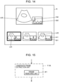
- the candidate frame extraction unit 11 can display, for each of the ultrasound images UC of the plurality of candidate frames, a graph G1 that represents a time-series change of the feature quantity and in which a marker H1 representing a time-series position of the ultrasound image UC of the candidate frame is placed as illustrated in Fig. 14 .
- a graph G1 that represents a time-series change of the feature quantity and in which a marker H1 representing a time-series position of the ultrasound image UC of the candidate frame is placed as illustrated in Fig. 14 .
- the ultrasound images UC of three candidate frames are displayed in a lower portion of the monitor 6, an ultrasound image U4 at the leftmost position is selected by the user, and an ultrasound image U5 that is the enlarged ultrasound image U4 of the frame selected by the user is displayed in an upper portion of the monitor 6 together with an enlarged graph G2 and an enlarged marker H2.
- the candidate frame extraction unit 11 may display, on the monitor 6, a value of the feature quantity for each of the ultrasound images UC of the candidate frames together with the ultrasound image UC of the candidate frame.
- the ultrasound image(s) UC of all the candidate frame(s) extracted by the candidate frame extraction unit 11 is (are) displayed on the monitor 6.
- the number-of-frames determination unit 30 determines that the ultrasound image UC of only one candidate frame is extracted, displaying of the ultrasound image UC of the candidate frame on the monitor 6 can be skipped.
- the plurality of local maximum values may include an outlier that is a markedly large value or a markedly small value because the urinary bladder region BR is not correctly extracted or the like.
- processing of removing an ultrasound image of a frame that has an outlier of the feature quantity from the ultrasound images UC of the plurality of candidate frames can be performed.
- An ultrasound diagnostic apparatus is equivalent to the ultrasound diagnostic apparatus 1 according to the first embodiment illustrated in Fig. 1 that includes a candidate frame extraction unit 11A illustrated in Fig. 15 instead of the candidate frame extraction unit 11.
- the candidate frame extraction unit 11A includes a frame removing unit 31.
- the frame removing unit 31 removes an ultrasound image of a frame having an outlier of the feature quantity from the ultrasound images UC of the plurality of candidate frames extracted by the candidate frame extraction unit 11A.
- the frame removing unit 31 analyzes the time-series change of the feature quantity calculated by the feature quantity calculation unit 10 and calculates a maximum value among a plurality of local maximum values of the feature quantity.
- the frame removing unit 31 multiplies the calculated maximum value by a predetermined ratio that is greater than 0 and less than 1, for example, to set a feature quantity threshold determined relative to the maximum value such that the feature quantity threshold is a value smaller than the maximum value.
- the frame removing unit 31 can remove an ultrasound image of a frame having a local maximum value that is smaller than the feature quantity threshold among the plurality of local maximum values of the feature quantity, from the ultrasound images UC of the plurality of candidate frames.
- the ultrasound diagnostic apparatus can further reduce the load imposed on the user in selecting the ultrasound image UD of the measurement frame and can increase the accuracy of urine volume measurement.
- the frame removing unit 31 may remove an ultrasound image by using an average value of the local maximum values of the feature quantity in the ultrasound images of the frames for which the feature quantity calculated by the feature quantity calculation unit 10 becomes a local maximum.
- the frame removing unit 31 analyzes a time-series change of the feature quantity calculated by the feature quantity calculation unit 10, and calculates an average value of the plurality of local maximum values of the feature quantity and a standard deviation of the feature quantity.
- the frame removing unit 31 sets a feature quantity range determined relative to the average value of the local maximum values of the feature quantity such that the feature quantity range has, as a lower-limit value, a value obtained by subtracting a product of the standard deviation and a certain ratio from the average value and has, as an upper-limit value, a value obtained by adding the product of the standard deviation and the certain ratio to the average value.
- the frame removing unit 31 can remove an ultrasound image of a frame having a local maximum value of the feature quantity that is out of the feature quantity range among the plurality of local maximum values of the feature quantity, from the ultrasound images UC of the plurality of candidate frames.
- the urinary bladder region BR is not correctly extracted and thus the feature quantity is not correctly calculated because of movement of the ultrasound probe 21 that is not usually performed in scanning of the urinary bladder B such as a shift in the position of the ultrasound probe 21 while the user is scanning the urinary bladder B or strong pressing of the ultrasound probe 21 against the body surface S of the subject to avoid gas accumulated in the abdomen of the subject.
- An ultrasound image of a frame generated, in scanning of the urinary bladder B, in response to such movement of the ultrasound probe 21 that is not usually performed may be removed from the ultrasound images UC of the plurality of candidate frames.
- An ultrasound diagnostic apparatus has the same configuration as the ultrasound diagnostic apparatus according to the third embodiment.
- the area of the urinary bladder region BR usually changes in time series to alternately have the local maximum values M1 to M5 and the local minimum values N1 to N4 as illustrated in Fig. 6 and differences between a local maximum value and a local minimum value that are adjacent to each other in time series are within a certain range.
- differences between a local maximum value and a local minimum value that are adjacent to each other in time series may be smaller than the certain range as illustrated in Fig. 16 , for example.
- the ultrasound images of the frames having the local maximum values M7 to M9 of the feature quantity can be estimated to be ultrasound images of frames generated, in scanning of the urinary bladder B, in response to movement of the ultrasound probe 21 that is not usually performed in scanning of the urinary bladder B.
- the frame removing unit 31 has a predetermined difference threshold for the differences between the local maximum values M6 to M10 and the local minimum values N6 to N10.
- the frame removing unit 31 analyzes a time-series change of the feature quantity calculated by the feature quantity calculation unit 10 and calculates differences between the local maximum values M6 to M10 and the local minimum values N6 to N10 that are adjacent to each other in time series. If the calculated difference is smaller than the predetermined difference threshold, the frame removing unit 31 removes an ultrasound image of a frame having that local maximum value from the ultrasound images of the plurality of candidate frames.
- the frame removing unit 31 extracts ultrasound images of five frames for which the feature quantity has the local maximum values M6 to M10, as the ultrasound images UC of the candidate frames, and calculates differences between the local maximum values M6 to M10 and the respective adjacent local minimum values N6 to N10 in time series. If the differences between the local maximum values M7 to M9 of the feature quantity and the respective adjacent local minimum values N7 to N9 in time series are smaller than the predetermined difference threshold, the frame removing unit 31 removes the ultrasound images of the three frames having the local maximum values M7 to M9 from the ultrasound images UC of the five candidate frames.
- the ultrasound diagnostic apparatus according to the fourth embodiment can constitute the ultrasound images UC of the plurality of candidate frames by ultrasound images of frames generated through normal scanning of the urinary bladder B, it is more likely that the ultrasound image UD of the measurement frame suitable for urine volume measurement is selected from among the ultrasound images UC of the plurality of candidate frames.
- the ultrasound diagnostic apparatus according to the fourth embodiment can further reduce the load imposed on the user and increase the accuracy of urine volume measurement.
- the ultrasound images UC of the plurality of candidate frames when the ultrasound images UC of the plurality of candidate frames are extracted by the candidate frame extraction unit 11, the ultrasound images UC of the plurality of candidate frames can be sorted based on a certain criterion and the sorted ultrasound images UC can be displayed on the monitor 6 to make it easier for the user to select the ultrasound image UD of the measurement frame from among the ultrasound images UC of the plurality of candidate frames.
- An ultrasound diagnostic apparatus is equivalent to the ultrasound diagnostic apparatus 1 according to the first embodiment illustrated in Fig. 1 that includes a candidate frame extraction unit 11B illustrated in Fig. 17 instead of the candidate frame extraction unit 11.
- the candidate frame extraction unit 11B includes a frame sorting unit 32.
- an ultrasound image of a frame for which the feature quantity such as the area or largest diameter of the urinary bladder region BR calculated by the feature quantity calculation unit 10 becomes a local maximum corresponds to a scan cross-section that passes through the vicinity of the center of the urinary bladder B and the ultrasound image corresponds to a scan cross-section that passes a portion closer to the center of the urinary bladder B as the value of the feature quantity becomes larger.
- the frame sorting unit 32 sorts the ultrasound images UC of the plurality of candidate frames extracted by the candidate frame extraction unit 11B in descending order of the feature quantity such as the area or largest diameter of the urinary bladder region BR, and displays the sorted ultrasound images UC of the plurality of candidate frames on the monitor 6.
- the ultrasound diagnostic apparatus can sort the ultrasound images UC of the plurality of candidate frames based on a certain criterion and display the sorted ultrasound images of the plurality of candidate frames on the monitor 6.
- Conceivable indices for use in determining whether or not the urinary bladder region BR is correctly depicted in an ultrasound image may be, for example, a roundness of the urinary bladder region BR and an edge clarity of the urinary bladder region BR.
- the roundness of the urinary bladder region BR is an index that has a larger value as the shape of the urinary bladder region BR is a circular shape and has a smaller value as the shape of the urinary bladder region BR is a non-circular shape.
- the edge clarity of the urinary bladder region BR is an index value that has a larger value as the outline of the bladder region BR becomes clear and has a smaller value as the outline of the bladder region BR becomes unclear.
- the roundness or the edge clarity of the urinary bladder region BR becomes larger, it can be determined that the urinary bladder region BR is depicted more correctly in the ultrasound image. As the roundness or the edge clarity of the urinary bladder region BR becomes smaller, it can be determined that urinary bladder region BR is not depicted correctly in the ultrasound image because of some reason.
- the frame sorting unit 32 may analyze the ultrasound images UC of the plurality of candidate frames to calculate, as the index value, the roundness or the edge clarity of the urinary bladder region BR in the ultrasound images UC of the plurality of candidate frames and sort the ultrasound images UC of the plurality of candidate frames in descending order of the calculated index value. In this case, it is easier for the user to select an ultrasound image of a frame in which the urinary bladder region BR is correctly depicted from among the ultrasound images UC of the plurality of candidate frames, and the accuracy of urine volume measurement can be increased.
- the frame sorting unit 32 can perform sorting using the feature quantity and sorting using the index value in combination.
- the frame sorting unit 32 sorts the ultrasound images UC of the plurality of candidate frames in descending order of the feature quantity and then divides the sorted ultrasound images of the plurality of candidate frames into groups of a certain number of frames such as three frames. In each of the groups of the candidate frames, the frame sorting unit 32 sorts the ultrasound images in descending order of the index.
- the frame sorting unit 32 can sort the ultrasound images UC of the plurality of candidate frames such that the plurality of groups in the ultrasound images UC of the candidate frames are sorted in descending order of the feature quantity and the ultrasound images UC of the plurality of candidate frame in each of the groups are sorted in descending order of the index value.
- the user can select the ultrasound image UD of the measurement frame from among the ultrasound images UC of the plurality of candidate frames by taking into account both the feature quantity and the index value related to the urinary bladder region BR.
- the user can select the ultrasound image UD of the suitable measurement frame, and the accuracy of urine volume measurement can be increased.
- the ultrasound probe 21 When the urinary bladder B is scanned using the swing method, the ultrasound probe 21 is usually placed at a position determined by the user that the largest urinary bladder region BR is depicted, and the ultrasound probe 21 is inclined at the position.
- an inclination angle is set such that the inclination angle of the ultrasound probe 21 in a state in which the ultrasound probe 21 is oriented in a direction perpendicular to the body surface S of the subject is 0 and the inclination angle increases as the ultrasound probe 21 is inclined more
- an ultrasound image of a frame generated in a state in which the inclination angle is close to 0 corresponds to a scan cross-section that passes through the vicinity of the center of the urinary bladder B.
- an angle sensor (not illustrated) for detecting the inclination angle of the ultrasound probe 21 may be attached to the ultrasound probe 21, and the value of the inclination angle of the ultrasound probe 21 detected by the angle sensor may be used as an index value for use in sorting the ultrasound images UC of the plurality of candidate frames.
- the angle sensor includes, for example, a so-called gyro sensor, an acceleration sensor, a magnetic sensor, or the like. The angle sensor converts an electric signal obtained from the gyro sensor, the acceleration sensor, the magnetic sensor, or the like into the inclination angle of the ultrasound probe 21 by using a well-known calculation method or the like.
- the ultrasound images UC of the plurality of candidate frames are sorted using the inclination angle of the ultrasound probe 21 as the index value, it becomes easier for the user to select an ultrasound image of a frame suitable for urine volume measurement, and the accuracy of urine volume measurement can be increased.
- the ultrasound diagnostic apparatus 1 has a configuration in which the monitor 6, the input device 15, and the ultrasound probe 21 are directly connected to the processor 22.
- the monitor 6, the input device 15, the ultrasound probe 21, and the processor 22 may be connected indirectly to each other via a network.
- an ultrasound diagnostic apparatus 1C in an ultrasound diagnostic apparatus 1C according to a sixth embodiment, the monitor 6, the input device 15, and the ultrasound probe 21 are connected to an ultrasound diagnostic apparatus main body 41 via a network NW.
- the ultrasound diagnostic apparatus main body 41 is equivalent to the ultrasound diagnostic apparatus 1 according to the first embodiment illustrated in Fig. 1 from which the monitor 6, the input device 15, and the ultrasound probe 21 are omitted, and is constituted by the image memory 7 and a processor 22C.
- the ultrasound diagnostic apparatus 1C having such a configuration calculates a feature quantity related to the urinary bladder region BR, such as the area of the urinary bladder region BR, in each of the ultrasound images of the plurality of frames stored in the image memory 8, extracts an ultrasound image of at least one frame for which the feature quantity becomes a local maximum as the ultrasound image of the at least one candidate frame, and selects the ultrasound image U2 of the frame selected by the user as the ultrasound image UD of the measurement frame from the ultrasound image UC of the at least one candidate frame displayed on the monitor 6.
- the ultrasound diagnostic apparatus can reduce the load imposed on the user.
- the ultrasound image UC of the at least one candidate frame includes an ultrasound image of a frame in which the urinary bladder region BR is erroneously detected
- the ultrasound image UD of the measurement frame suitable for urine volume measurement can be selected and the accuracy of urine volume measurement can be increased.
- the ultrasound diagnostic apparatus main body 41 can be used as a so-called remote server.
- the user can examine the subject by preparing the monitor 6, the input device 15, and the ultrasound probe 21, so that convenience at the time of ultrasonic diagnosis can be improved.
- the user when a thin portable computer called a tablet is used as the monitor 6 and the input device 15, the user can more easily perform urine volume measurement. Thus, convenience of the urine volume measurement can be further improved.
- the monitor 6, the input device 15, and the ultrasound probe 21 are connected to the ultrasound diagnostic apparatus main body 41 via the network NW. At this time, the monitor 6, the input device 15, and the ultrasound probe 21 may be connected to the network NW with cables or wirelessly.
Landscapes
- Health & Medical Sciences (AREA)
- Engineering & Computer Science (AREA)
- Public Health (AREA)
- Life Sciences & Earth Sciences (AREA)
- Medical Informatics (AREA)
- General Health & Medical Sciences (AREA)
- Biomedical Technology (AREA)
- Pathology (AREA)
- Nuclear Medicine, Radiotherapy & Molecular Imaging (AREA)
- Radiology & Medical Imaging (AREA)
- Primary Health Care (AREA)
- Epidemiology (AREA)
- Animal Behavior & Ethology (AREA)
- Physics & Mathematics (AREA)
- Biophysics (AREA)
- Molecular Biology (AREA)
- Surgery (AREA)
- Heart & Thoracic Surgery (AREA)
- Veterinary Medicine (AREA)
- Physiology (AREA)
- Computer Vision & Pattern Recognition (AREA)
- Databases & Information Systems (AREA)
- Data Mining & Analysis (AREA)
- Vascular Medicine (AREA)
- Ultra Sonic Daignosis Equipment (AREA)
Abstract
Description
- The present invention relates to an ultrasound diagnostic apparatus for measuring a urine volume in a urinary bladder of a subject, a method for controlling the ultrasound diagnostic apparatus, and a processor for the ultrasound diagnostic apparatus.
- In the related art, an ultrasound diagnostic apparatus is used to observe the urinary bladder of a subject and measure the urine volume in the observed urinary bladder. In general, the urine volume in the urinary bladder of a subject is substantially equal to the volume of the urinary bladder of the subject. Thus, the volume of the urinary bladder of the subject is measured as the urine volume. To perform such urine volume measurement easily, for example, an ultrasound diagnostic apparatus of
JP2017-109074A JP2017-109074A - However, the ultrasound diagnostic apparatus of
JP2017-109074A - In addition, when the user attempts to manually select an ultrasound image of a frame subjected to urine volume measurement in order to select the ultrasound image of the suitable frame, the user needs to check ultrasound images of a large number of frames. Consequently, there is an issue in that a great deal of labor is required.
- The present invention is made to overcome such issues in the related art, and an object thereof is to provide an ultrasound diagnostic apparatus capable of increasing the accuracy of urine volume measurement while reducing a load imposed on a user, a method for controlling the ultrasound diagnostic apparatus, and a processor for the ultrasound diagnostic apparatus.
- To achieve the object above, an ultrasound diagnostic apparatus according to the present invention includes an image memory configured to store ultrasound images of a plurality of frames; a urinary bladder extraction unit configured to extract a urinary bladder region from each of the ultrasound images of the plurality of frames; a feature quantity calculation unit configured to calculate a feature quantity related to the urinary bladder region extracted for each of the ultrasound images of the plurality of frames by the urinary bladder extraction unit; a candidate frame extraction unit configured to extract, from the ultrasound images of the plurality of frames, an ultrasound image of a frame for which the feature quantity calculated by the feature quantity calculation unit becomes a local maximum, as an ultrasound image of at least one candidate frame that serves as a candidate subjected to measurement; a measurement frame selection unit configured to select an ultrasound image of a measurement frame that serves as a target subjected to measurement from the ultrasound image of the at least one candidate frame extracted by the candidate frame extraction unit; and a urine volume measurement unit configured to analyze the ultrasound image of the measurement frame selected by the measurement frame selection unit to measure a urine volume.
- In a case where a difference between a local maximum value of the feature quantity in the ultrasound image of the frame for which the feature quantity calculated by the feature quantity calculation unit becomes the local maximum and a local minimum value of the feature quantity adjacent to the local maximum value in time series is smaller than a predetermined difference threshold, the candidate frame extraction unit can remove the ultrasound image of the frame for which the feature quantity becomes the local maximum from the ultrasound image of the at least one candidate frame.
- Alternatively, the candidate frame extraction unit can remove, from the ultrasound image of the at least one candidate frame, an ultrasound image of a frame having a local maximum value of the feature quantity that is smaller than a feature quantity threshold determined relative to a maximum value of the feature quantity in ultrasound images of frames for each of which the feature quantity calculated by the feature quantity calculation unit becomes a local maximum.
- Alternatively, the candidate frame extraction unit can remove, from the ultrasound image of the at least one candidate frame, an ultrasound image of a frame having a local maximum value of the feature quantity that is outside a feature quantity range determined relative to an average value of local maximum values of the feature quantity in ultrasound images of frames for each of which the feature quantity calculated by the feature quantity calculation unit becomes a local maximum.
- The ultrasound diagnostic apparatus can further include a monitor configured to display the ultrasound image of the at least one candidate frame extracted by the candidate frame extraction unit.
- In this case, the extracted ultrasound image of the at least one candidate frame can include extracted ultrasound images of one or more candidate frames, and the candidate frame extraction unit can calculate, as an index value, a roundness of the urinary bladder region or an edge clarity of the urinary bladder region for each of the extracted ultrasound images of the one or more candidate frames, sort the ultrasound images of the one or more candidate frames based on the calculated index value, and cause the monitor to display the sorted ultrasound images of the one or more candidate frames.
- The extracted ultrasound image of the at least one candidate frame can include extracted ultrasound images of one or more candidate frames, and the candidate frame extraction unit can cause the monitor to display each of the extracted ultrasound images of the one or more candidate frames and a graph that represents a time-series change in the feature quantity and in which a marker representing a time-series position corresponding to the ultrasound image of the candidate frame is placed.
- The extracted ultrasound image of the at least one candidate frame can include extracted ultrasound images of one or more candidate frames, and the candidate frame extraction unit can cause the monitor to display each of the extracted ultrasound images of the one or more candidate frames and a value of the feature quantity corresponding to the ultrasound image of the candidate frame.
- The ultrasound diagnostic apparatus can further include an input device with which the user performs an input operation. In this case, the measurement frame selection unit can select, as the ultrasound image of the measurement frame, an ultrasound image of a frame selected by the user via the input device from the ultrasound image of the at least one candidate frame displayed on the monitor.
- Alternatively, the ultrasound diagnostic apparatus can include an input device with which the user performs an input operation. In this case, the measurement frame selection unit can determine whether or not ultrasound images of a plurality of candidate frames are extracted by the candidate frame extraction unit, in a case of determining that ultrasound images of a plurality of candidate frames are extracted by the candidate frame extraction unit, select, as the ultrasound image of the measurement frame, an ultrasound image of a frame selected by the user via the input device from the ultrasound images of the plurality of candidate frames displayed on the monitor, and in a case of determining that an ultrasound image of only one candidate frame is extracted by the candidate frame extraction unit, select the ultrasound image of the only one candidate frame as the ultrasound image of the measurement frame.
- A method for controlling an ultrasound diagnostic apparatus according to the present invention includes extracting a urinary bladder region from each of ultrasound images of a plurality of frames; calculating a feature quantity related to the urinary bladder region extracted for each of the ultrasound images of the plurality of frames; extracting, from the ultrasound images of the plurality of frames, an ultrasound image of a frame for which the calculated feature quantity becomes a local maximum, as an ultrasound image of at least one candidate frame that serves as a candidate subjected to measurement; selecting an ultrasound image of a measurement frame that serves as a target subjected to measurement from the ultrasound image of the at least one candidate frame; and analyzing the selected ultrasound image of the measurement frame to measure a urine volume.
- A processor for an ultrasound diagnostic apparatus according to the present invention is configured to extract a urinary bladder region from each of ultrasound images of a plurality of frames; calculate a feature quantity related to the urinary bladder region extracted for each of the ultrasound images of the plurality of frames; extract, from the ultrasound images of the plurality of frames, an ultrasound image of a frame for which the calculated feature quantity becomes a local maximum, as an ultrasound image of at least one candidate frame that serves as a candidate subjected to measurement; select an ultrasound image of a measurement frame that serves as a target subjected to measurement from the ultrasound image of the at least one candidate frame; and analyze the selected ultrasound image of the measurement frame to measure a urine volume.
- According to the present invention, the ultrasound diagnostic apparatus includes the urinary bladder extraction unit that extracts a urinary bladder region from each of ultrasound images of a plurality of frames; the feature quantity calculation unit that calculates a feature quantity related to the urinary bladder region extracted for each of the ultrasound images of the plurality of frames by the urinary bladder extraction unit; the candidate frame extraction unit that extracts, from the ultrasound images of the plurality of frames, an ultrasound image of a frame for which the feature quantity calculated by the feature quantity calculation unit becomes a local maximum, as an ultrasound image of at least one candidate frame that serves as a candidate subjected to measurement; the measurement frame selection unit that selects an ultrasound image of a measurement frame that serves as a target subjected to measurement from the ultrasound image of the at least one candidate frame extracted by the candidate frame extraction unit; and the urine volume measurement unit that analyzes the ultrasound image of the measurement frame selected by the measurement frame selection unit to measure a urine volume. Thus, the ultrasound diagnostic apparatus can increase the accuracy of urine volume measurement while reducing the load imposed on a user.
-
-
Fig. 1 is a block diagram illustrating a configuration of an ultrasound diagnostic apparatus according to a first embodiment of the present invention; -
Fig. 2 is a block diagram illustrating an internal configuration of a transmission/reception circuit in the first embodiment of the present invention; -
Fig. 3 is a block diagram illustrating an internal configuration of an image generation unit in the first embodiment of the present invention; -
Fig. 4 is a diagram schematically illustrating an example of an ultrasound image including a urinary bladder region in the first embodiment of the present invention; -
Fig. 5 is a diagram schematically illustrating how a urinary bladder is scanned using a swing method; -
Fig. 6 is a diagram illustrating an example of a time-series change of an area of a urinary bladder region in the first embodiment of the present invention; -
Fig. 7 is a diagram illustrating an example of an ellipsoid; -
Fig. 8 is a diagram schematically illustrating an example of ultrasound images of a plurality of candidate frames displayed in the first embodiment of the present invention; -
Fig. 9 is a flowchart illustrating an operation of the ultrasound diagnostic apparatus according to the first embodiment of the present invention; -
Fig. 10 is a diagram schematically illustrating an example in which a urine volume in a urinary bladder of a subject is displayed on a monitor in the first embodiment of the present invention; -
Fig. 11 is a diagram schematically illustrating how a urinary bladder is scanned using a slide method; -
Fig. 12 is a block diagram illustrating an internal configuration of a measurement frame selection unit in a second embodiment of the present invention; -
Fig. 13 is a flowchart illustrating an operation of selecting an ultrasound image of a measurement frame in the second embodiment of the present invention; -
Fig. 14 is a diagram schematically illustrating an example of ultrasound images of a plurality of candidate frames and graphs displayed in the second embodiment of the present invention; -
Fig. 15 is a block diagram illustrating an internal configuration of a candidate frame extraction unit in a third embodiment of the present invention; -
Fig. 16 is a diagram illustrating an example of a time-series change of an area of a urinary bladder region in the third embodiment of the present invention; -
Fig. 17 is a block diagram illustrating an internal configuration of a candidate frame extraction unit in a fifth embodiment of the present invention; and -
Fig. 18 is a block diagram illustrating a configuration of an ultrasound diagnostic apparatus according to a sixth embodiment of the present invention. - Embodiments of this invention will be described below with reference to the accompanying drawings.
- The description of constituent elements below is given based on representative embodiments of the present invention. However, the present invention is not limited to such embodiments.
- In the present specification, a numerical range expressed using "to" means a range including a numerical value preceding "to" as a lower limit value and a numerical value following "to" as an upper limit value.
- In the present specification, the terms "identical" and "same" include an error range generally acceptable in the technical field.
-
Fig. 1 illustrates a configuration of an ultrasounddiagnostic apparatus 1 according to a first embodiment of the present invention. The ultrasounddiagnostic apparatus 1 includes atransducer array 2. A transmission/reception circuit 3, animage generation unit 4, adisplay control unit 5, and amonitor 6 are sequentially connected to thetransducer array 2. Thetransducer array 2 and the transmission/reception circuit 3 are included in anultrasound probe 21. Animage memory 7 is connected to theimage generation unit 4. A urinarybladder extraction unit 9, a featurequantity calculation unit 10, a candidateframe extraction unit 11, a measurementframe selection unit 12, and a urinevolume measurement unit 13 are sequentially connected to theimage memory 7. The candidateframe extraction unit 11 and the urinevolume measurement unit 13 are connected to thedisplay control unit 5. - A
device control unit 14 is connected to the transmission/reception circuit 3, theimage generation unit 4, thedisplay control unit 5, the urinarybladder extraction unit 9, the featurequantity calculation unit 10, the candidateframe extraction unit 11, the measurementframe selection unit 12, and the urinevolume measurement unit 13. Aninput device 15 is connected to thedevice control unit 14. - The
image generation unit 4, thedisplay control unit 5, the urinarybladder extraction unit 9, the featurequantity calculation unit 10, the candidateframe extraction unit 11, the measurementframe selection unit 12, the urinevolume measurement unit 13, and thedevice control unit 14 constitute aprocessor 22 for the ultrasounddiagnostic apparatus 1. - The
transducer array 2 of theultrasound probe 21 illustrated inFig. 1 has a plurality of transducers arranged one-dimensionally or two-dimensionally. Each of these transducers transmits an ultrasonic wave in accordance with a drive signal supplied from the transmission/reception circuit 3. Each of these transducers also receives an ultrasonic echo from the subject, and outputs a signal based on the ultrasonic echo. Each of the transducers is configured by forming electrodes at respective ends of a piezoelectric body made of, for example, a piezoelectric ceramic represented by lead zirconate titanate (PZT), a polymer piezoelectric element represented by polyvinylidene difluoride (PVDF), and a piezoelectric single crystal represented by lead magnesium niobate-lead titanate (PMN-PT). - Under the control of the
device control unit 14, the transmission/reception circuit 3 transmits ultrasonic waves from thetransducer array 2, and generates a sound ray signal based on reception signals acquired by thetransducer array 2. As illustrated inFig. 2 , the transmission/reception circuit 3 has apulser 23 connected to thetransducer array 2, and anamplifier 24, an analog-to-digital (AD)converter 25, and abeamformer 26 sequentially connected in series from thetransducer array 2. - The
pulser 23 includes, for example, a plurality of pulse generators. Thepulser 23 adjusts delay amounts of respective drive signals, based on a transmission delay pattern selected in accordance with a control signal from thedevice control unit 14 so that ultrasonic waves transmitted from the plurality of transducers of thetransducer array 2 form an ultrasonic beam, and supplies the resulting drive signals to the respective transducers. As described above, in response to application of a pulsed or continuous-wave voltage to the electrodes of the transducers of thetransducer array 2, the piezoelectric body expands and contracts. Consequently, pulsed or continuous-wave ultrasonic waves are generated from the respective transducers, and an ultrasonic beam is formed from a composite wave of those ultrasonic waves. - The transmitted ultrasonic beam is reflected by a target such as a part of a subject, for example, and propagates toward the
transducer array 2 of theultrasound probe 21. An ultrasonic echo propagating toward thetransducer array 2 in this manner is received by each of the transducers of thetransducer array 2. At this time, in response to receipt of the propagating ultrasonic echo, the transducers of thetransducer array 2 expand and contract to generate respective reception signals, which are electric signals, and output these reception signals to theamplifier 24. - The
amplifier 24 amplifies a signal input from each of the transducers of thetransducer array 2, and transmits the amplified signal to theAD converter 25. TheAD converter 25 converts the signals transmitted from theamplifier 24 into pieces of digital reception data, and transmits these pieces of reception data to thebeamformer 26. Thebeamformer 26 performs so-called reception focusing processing in which the pieces of reception data obtained by theAD converter 25 through conversion are given respective delays and then are added in accordance with sonic velocities or a sonic velocity distribution set based on a reception delay pattern selected in accordance with the control signal from thedevice control unit 14. Through this reception focusing processing, the pieces of reception data obtained by theAD converter 25 through the conversion are subjected to phasing addition, and a sound ray signal to which the focus of the ultrasonic echo converges is acquired. - As illustrated in
Fig. 3 , theimage generation unit 4 has a configuration in which asignal processing unit 27, a digital scan converter (DSC) 28, and animage processing unit 29 are sequentially connected in series. - In accordance with a depth of a reflected position of the ultrasonic waves, the
signal processing unit 27 performs distance-based attenuation correction on the sound ray signal generated by thebeamformer 26 of the transmission/reception circuit 3, and then performs envelope detection processing. In this manner, thesignal processing unit 27 generates a B-mode image signal, which is tomographic image information related to a tissue in the subject. - The
DSC 28 converts (raster-converts) the B-mode image signal generated by thesignal processing unit 27 into an image signal according to a normal television signal scanning method. - The
image processing unit 29 performs various kinds of necessary image processing such as grayscale processing on the B-mode image signal input from theDSC 28, and then outputs the B-mode image signal to thedisplay control unit 5 and theimage memory 7. Hereinafter, the B-mode image signal on which the image processing has been performed by theimage processing unit 29 is simply referred to as an ultrasound image. - The
image memory 7 is a memory that stores ultrasound images of a series of frames generated by theimage generation unit 4 for each diagnosis. Theimage memory 7 to be used may be a recording medium such as a flash memory, a hard disc drive (HDD), a solid state drive (SDD), a flexible disc (FD), a magneto-optical disc (MO), a magnetic tape (MT), a random access memory (RAM), a compact disc (CD), a digital versatile disc (DVD), a secure digital (SD) card, or a Universal Serial Bus (USB) memory; a server; or the like. - For example, as illustrated in
Fig. 4 , the urinarybladder extraction unit 9 extracts a urinary bladder region BR from an ultrasound image U1. For example, the urinarybladder extraction unit 9 can use a technique using deep learning described in Krizhevsk et al.: ImageNet Classification with Deep Convolutional Neural Networks, Advances in Neural ) to extract the urinary bladder region BR in the ultrasound image U1. Alternatively, the urinarybladder extraction unit 9 can use, as another technique, a known technique such as graph cut (Y Boykov and V. Kolmogorov, "An experimental comparison of min-cut/max-flow algorithm for energy minimization in vision", IEEE Transactions on Pattern Analysis and Machine Intelligence, 26, 9, pp. 1123-1137, 2004.), Snakes (A. W. Michael Kass and D. Terzopoulos: "Snakes: Active contour models", Int. J. Computer Vision, 1, 4, pp. 321-331, 1988.), or Level Sets (M. Sussman, P. Smereka, and S. Osher: "A level set approach for computing solutions to incompressible two-phase flow", J. Comput. Phys, 114, 1, pp. 146-159, 1994) to extract the urinary bladder region BR. - The feature
quantity calculation unit 10 calculates a feature quantity related to the extracted urinary bladder region BR in the ultrasound image U1 from which the urinary bladder region BR has been extracted by the urinarybladder extraction unit 9. Through image analysis, the featurequantity calculation unit 10 can calculate, as the feature quantity, an area of the extracted urinary bladder region BR, for example. Through image analysis, the featurequantity calculation unit 10 can calculate, as the feature quantity, the largest diameters of the urinary bladder region BR in three directions orthogonal to each other, which are used for measuring the volume of the urinary bladder described below, for example. Through image analysis, the featurequantity calculation unit 10 can calculate, as the feature quantity, the largest diameter in any direction of the extracted urinary bladder region BR, the circumferential length of the urinary bladder region BR, or the like. - When the
image generation unit 4 generates ultrasound images of frames including the urinary bladder region BR of the subject, the user usually scans the urinary bladder by changing the position or angle of theultrasound probe 21 while keeping theultrasound probe 21 in contact with the body surface of the subject. At this time, the user can scan the urinary bladder by using, for example, a swing method in which theultrasound probe 21 is inclined on the body surface of the subject while the position of theultrasound probe 21 is fixed. - When the user scans the urinary bladder using the swing method, the user inclines the
ultrasound probe 21 on a body surface S of the subject back and forth between an inclination angle at which a scan cross-section PS1 that passes through one end of a urinary bladder B is imaged and an inclination angle at which a scan cross-section PS2 that passes through the other end of the urinary bladder B with respect to a rotational axis R that is parallel to the arrangement direction of thetransducer array 2 as illustrated inFig. 5 , for example. - At this time, the value of the area of the urinary bladder region BR included in the ultrasound images of the frames consecutively generated by the
image generation unit 4 changes in time series such that the value alternately has a local maximum value and a local minimum value as illustrated inFig. 6 , for example. The example ofFig. 6 presents a relationship between the area of the urinary bladder region BR and the generation time of the ultrasound image of the frame for which the area of the urinary bladder region BR is calculated, and the value of the area of the urinary bladder region BR changes in time series to have five local maximum values M1 to M5 and four local minimum values N1 to N4. While the example ofFig. 6 presents the time-series change of the value of the area of the urinary bladder region BR, the largest diameter of the urinary bladder region BR also shows a time-series change as illustrated inFig. 6 . - In general, the urinary bladder B of the subject usually has a substantially ellipsoidal shape. Thus, the urine volume in the urinary bladder B is measured by calculating the volume of the urinary bladder B while the urinary bladder B is regarded as an ellipsoid. As illustrated in
Fig. 7 , when an ellipsoid E has a symmetrical shape with respect to an XY plane, an YZ plane, and an XZ plane, it is known that the volume of the ellipsoid E is calculated by (LX × LY × LZ) × π/6, where LX is the largest diameter of the ellipsoid E in the X direction, LY is the largest diameter of the ellipsoid E in the Y direction, LZ is the largest diameter of the ellipsoid E in the Z direction, and π is the circumference ratio. Thus, when the volume of the urinary bladder B is calculated using an ultrasound image, it is desirable to perform measurement on ultrasound images of two frames corresponding to scan cross-sections that pass through the center of the urinary bladder B and are orthogonal to each other. - As described above, the ultrasound image of the frame that corresponds to a scan cross-section that passes through the center of the urinary bladder B is an ultrasound image of a frame for which the feature quantities such as the area and the largest diameter of the urinary bladder region BR become a local maximum in the time-series change when the urinary bladder B is scanned using the swing method, for example.
- The candidate
frame extraction unit 11 extracts ultrasound images of frames for which the feature quantity calculated by the featurequantity calculation unit 10 for each of the ultrasound images of the plurality of frames stored in theimage memory 7 becomes a local maximum, as ultrasound images of candidate frames that serve as measurement candidates of urine volume measurement. In the example ofFig. 6 , the candidateframe extraction unit 11 extracts ultrasound images of five frames for which the value of the area of the urinary bladder region BR is the local maximum values M1 to M5, as the ultrasound images of the candidate frames. - For example, as illustrated in
Fig. 8 , the candidateframe extraction unit 11 causes themonitor 6 to display an extracted ultrasound image UC of at least one candidate frame. In the example illustrated inFig. 8 , ultrasound images UC of five candidate frames are displayed in a lower portion of themonitor 6. When the ultrasound images UC of the plurality of candidate frames are extracted, the candidateframe extraction unit 11 can display the extracted ultrasound images UC of all the candidate frames together on themonitor 6. The candidateframe extraction unit 11 can also display only some of the extracted ultrasound images UC of all the candidate frames together on themonitor 6 in so-called scroll display. - The
input device 15 is a device with which a user performs an input operation, and can include a keyboard, a mouse, a trackball, a touch pad, a touch panel, and the like. - The measurement
frame selection unit 12 selects, as a measurement frame that serves as a target subjected to measurement, an ultrasound image of a frame selected by the user via theinput device 15 from the ultrasound image UC of the at least one candidate frame displayed on themonitor 6. For example, inFig. 8 , an ultrasound image U2 of a frame selected by the user from among the ultrasound images UC of the five candidate frames displayed in the lower portion of themonitor 6 is displayed with a thick frame, and the ultrasound image U2 of this frame is selected as the ultrasound image of the measurement frame by the measurementframe selection unit 12. - The urine
volume measurement unit 13 calculates the volume of the urinary bladder B of the subject based on the ultrasound image of the measurement frame selected by the measurementframe selection unit 12 to measure the urine volume in the urinary bladder B. For example, when ultrasound images of two measurement frames corresponding to scan cross-sections that pass through the center of the urinary bladder B and are orthogonal to each other are selected by the measurementframe selection unit 12, the urinevolume measurement unit 13 measures lengths of the urinary bladder region BR in the ultrasound images of the two measurement frames, acquires the largest diameters LX, LY, and LZ in the three directions orthogonal to each other, and calculate (LX × LY × LZ) × π/6. In this manner, the urinevolume measurement unit 13 can calculate the volume of the urinary bladder B of the subject. - Under the control of the
device control unit 14, thedisplay control unit 5 performs predetermined processing on the ultrasound images of the frames stored in theimage memory 7, the ultrasound image UC of at least one candidate frame extracted by the candidateframe extraction unit 11, and information indicating the value of the urine volume in the urinary bladder of the subject measured by the urinevolume measurement unit 13, and displays the images and the information on themonitor 6. - Under the control of the
display control unit 5, themonitor 6 displays the ultrasound images of the frames generated by theimage generation unit 4, the ultrasound images of the frames stored in theimage memory 7, the ultrasound image UC of the at least one candidate frame, the value of the urine volume in the urinary bladder of the subject, and the like. Themonitor 6 includes a display device such as a liquid crystal display (LCD) or an organic electroluminescence (EL) display, for example. - The
device control unit 14 controls each unit of the ultrasounddiagnostic apparatus 1, based on a control program or the like stored in advance. - The
processor 22 having theimage generation unit 4, thedisplay control unit 5, the urinarybladder extraction unit 9, the featurequantity calculation unit 10, the candidateframe extraction unit 11, the measurementframe selection unit 12, the urinevolume measurement unit 13, and thedevice control unit 14 may be constituted by a central processing unit (CPU) and a control program for causing the CPU to perform various processes. However, theprocessor 22 may be constituted using a field programmable gate array (FPGA), a digital signal processor (DSP), an application specific integrated circuit (ASIC), a graphics processing unit (GPU), or another integrated circuit (IC), or any combination of these. - The
image generation unit 4, thedisplay control unit 5, the urinarybladder extraction unit 9, the featurequantity calculation unit 10, the candidateframe extraction unit 11, the measurementframe selection unit 12, the urinevolume measurement unit 13, and thedevice control unit 14 of theprocessor 22 may be partially or entirely integrated into a single CPU or the like. - An operation of the ultrasound
diagnostic apparatus 1 according to the first embodiment will be described in detail below with reference to a flowchart illustrated inFig. 9 . - First, in step S1, an ultrasound image is generated with the
ultrasound probe 21 being kept in contact with the body surface S of the subject by the user, and the generated ultrasound image is displayed on themonitor 6. At this time, an ultrasonic beam is transmitted from the plurality of transducers of thetransducer array 2 into the subject in accordance with drive signals from thepulser 23 of the transmission/reception circuit 3. The transducers receive an ultrasound echo from the subject and output respective reception signals to theamplifier 24 of the transmission/reception circuit 3. The reception signals are amplified by theamplifier 24, are subjected to AD conversion by theAD converter 25, and are then subjected to phasing addition by thebeamformer 26, so that a sound ray signal is generated. In theimage generation unit 4, this sound ray signal is subjected to envelope detection processing by thesignal processing unit 27 to be a B-mode image signal, and the B-mode image signal is output to thedisplay control unit 5 through theDSC 28 and theimage processing unit 29. Consequently, the ultrasound image U1 is displayed on themonitor 6 under the control of thedisplay control unit 5 as illustrated inFig. 4 . - At this time, the user adjusts the position and the inclination of the
ultrasound probe 21 while checking the ultrasound image U1 displayed on themonitor 6 so that the urinary bladder region BR of the subject is depicted in the ultrasound image U1. - Next, in step S2, it is determined whether or not a measurement mode for measuring the urine volume in the urinary bladder of the subject is started. For example, when an instruction for starting the measurement mode is given by the user via the
input device 15, it is determined that the measurement mode is started. When an instruction for starting the measurement mode is not given by the user, it is determined that the measurement mode is not started. If it is determined that the measurement mode is not started, the process returns to step S1, in which an ultrasound image is generated and displayed. If it is determined that the measurement mode is started in response to the user giving an instruction for starting the measurement mode after adjusting the position of theultrasound probe 21, the process proceeds to step S3. - If it is determined in step S2 that the measurement mode is started, an ultrasound image is generated as in step S1 and the generated ultrasound image is stored in the
image memory 7 in step S3. For example, the user scans the urinary bladder B using the swing method in which the urinary bladder B of the subject is imaged while an inclination of theultrasound probe 21 is changed. - In subsequent step S4, it is determined whether or not scanning of the urinary bladder B of the subject is ended. For example, when an instruction for ending scanning of the urinary bladder B is given by the user via the
input device 15, it is determined that scanning of the urinary bladder B is ended. When an instruction for ending scanning of the urinary bladder B is not given by the user, it is determined that scanning of the urinary bladder B continues. If it is determined that scanning of the urinary bladder B continues, the process returns to step S3, in which an ultrasound image is generated and stored. In this manner, steps S3 and S4 are repeated while scanning of the urinary bladder B continues. Consequently, ultrasound images of a plurality of frames are stored in theimage memory 7. If it is determined that scanning of the urinary bladder B is ended, the process proceeds to step S5. - In step S5, the urinary
bladder extraction unit 9 performs image analysis on each of the ultrasound images of the plurality of frames stored in theimage memory 7, and extracts the urinary bladder region BR representing the urinary bladder B of the subject. Information of the extracted urinary bladder region BR and the ultrasound images of the plurality of frames are sent to the featurequantity calculation unit 10. - In step S6, based on the urinary bladder region BR extracted in step S5 from each of the ultrasound images of the plurality of frames, the feature
quantity calculation unit 10 calculates, as a feature quantity related to the urinary bladder region BR, the area of the urinary bladder region BR. Since the user scans the urinary bladder B using the swing method in step S3, the area of the urinary bladder region BR calculated in step S6 changes in time series as illustrated inFig. 6 , for example. The information of the calculated area of the urinary bladder region BR and the ultrasound images of the plurality of frames are sent to the candidateframe extraction unit 11. - The urine volume in the urinary bladder B is measured by calculating the volume of the urinary bladder B while regarding the urinary bladder B to be the ellipsoid E. Thus, ultrasound images of frames corresponding to the scan cross-sections that pass through the center of the urinary bladder B are desirably used as the ultrasound images of the frames used in urine volume measurement. The ultrasound images of such frames are ultrasound images of frames for which the feature quantity of the urinary bladder region BR becomes a local maximum in the time-series change illustrated in
Fig. 6 . - Thus, in step S7, the candidate
frame extraction unit 11 extracts, as ultrasound images UC of candidate frames, ultrasound images of frames for which the area of the urinary bladder region BR that is calculated in step S6 for each of the ultrasound images of the plurality of frames and is received from the featurequantity calculation unit 10 becomes a local maximum. In the example ofFig. 6 , the candidateframe extraction unit 11 extracts, as the ultrasound images UC of the candidate frames, ultrasound images of five frames for which the area of the urinary bladder region BR takes the local maximum values M1 to M5. - In step S7, the candidate
frame extraction unit 11 displays the extracted ultrasound images UC of the five candidate frames on themonitor 6 as illustrated inFig. 8 , for example. In the example ofFig. 8 , the ultrasound images UC of the five candidate frames are displayed in the lower portion of themonitor 6. - In step S8, the user selects the ultrasound image U2 of one frame from among the ultrasound images UC of the five candidate frames displayed on the
monitor 6 via theinput device 15 as illustrated inFig. 8 . The ultrasound image U2 of the frame selected by the user is selected as the ultrasound image of the measurement frame by the measurementframe selection unit 12. InFig. 8 , the ultrasound image U2 of the frame indicated by a thick frame is selected by the user and is selected as the measurement frame by the measurementframe selection unit 12. At this time, for example, an ultrasound image U3 obtained by enlarging the ultrasound image U2 of the selected frame can be displayed on themonitor 6 to allow the user to easily check the ultrasound image U2 of the selected frame. - The ultrasound image U2 of the frame selected by the user is selected as the ultrasound image of the measurement frame from the ultrasound image UC of the at least one candidate frame displayed on the
monitor 6 in this manner. Thus, even if there is an ultrasound image of a frame in which the urinary bladder region BR is not correctly extracted in step S5 for some reason and the ultrasound image of this frame is included in the ultrasound images UC of the plurality of candidate frames extracted in step S7 because the feature quantity in the ultrasound image of this frame takes a local maximum value, the ultrasound image of the measurement frame can be selected from among the ultrasound images of the frames in which the urinary bladder region BR is correctly extracted. Consequently, the accuracy of urine volume measurement can be increased. Since the ultrasound image UC of the at least one candidate frame is automatically extracted based on the feature quantity related to the urinary bladder region BR from among the ultrasound images of the frames stored in theimage memory 7, the user need not check ultrasound images of many frames. Consequently, the load imposed on the user in selecting the ultrasound image of the measurement frame can be reduced. - In step S9, it is determined whether or not ultrasound images of two measurement frames corresponding to two scan cross-sections of the urinary bladder B of the subject orthogonal to each other is selected in step S8 in order to measure the urine volume in the urinary bladder B. In step S8 that has already been completed, only an ultrasound image of the measurement frame corresponding to one of the two scan cross-sections of the urinary bladder B orthogonal to each other has been acquired. Thus, it is determined that ultrasound images of two measurement frames corresponding to the two scan cross-sections of the urinary bladder B of the subject orthogonal to each other are not selected, the process returns to step S3, in which scanning of the urinary bladder B is resumed. At this time, the user rotates the orientation of the
ultrasound probe 21 by 90 degrees and scans the urinary bladder B. - In steps S3 and S4, an ultrasound image is repeatedly generated and stored unless the user gives an instruction for ending scanning of the urinary bladder B. In response to the user giving the instruction for ending scanning of the urinary bladder B in step S4, the process proceeds to step S5. Description of the subsequent processing of steps S5 to S8 is omitted since the details thereof are identical to those already described.
- In step S8, the ultrasound image U2 of the frame selected by the user is selected as the ultrasound image of the measurement frame from the ultrasound image UC of the at least one candidate frame displayed on the
monitor 6. The process then proceeds to step S9. - In step S9, it is determined whether or not the ultrasound images of the two measurement frames corresponding to the two scan cross-sections orthogonal to each other of the urinary bladder B of the subject are selected in step S8. In step S8 performed for the second time, the ultrasound image of the second measurement frame is selected. Thus, it is determined that the ultrasound images of the two measurement frames corresponding to the two scan cross-sections of the urinary bladder B of the subject orthogonal to each other are selected, and the process proceeds to step S10.
- In step S10, the urine
volume measurement unit 13 extracts the urinary bladder region BR from each of the ultrasound images of the two measurement frames selected by the user in step S8 performed twice and calculates the volume of the urinary bladder B of the subject based on the diameters of the extracted urinary bladder region BR to measure the urine volume in the urinary bladder B. For example, the urinevolume measurement unit 13 regards the urinary bladder B to be the ellipsoid E as illustrated inFig. 7 , measures the largest diameters LX, LY, and LZ respectively in the X, Y, and Z directions of the ellipsoid E from the ultrasound images of the two measurement frames selected by the user in step S8, and calculates (LX × LY × LZ) × π/6. In this manner, the urinevolume measurement unit 13 can calculate the volume of the ellipsoid E as the volume of the urinary bladder B. For example, as illustrated inFig. 10 , the urinevolume measurement unit 13 displays a measured urine volume J in the urinary bladder B on themonitor 6. In the example ofFig. 10 , the ultrasound image UD of the measurement frame selected by the user in the step S9 performed for the second time and the urine volume J in the urinary bladder B are displayed together on themonitor 6. - In response to the urine volume in the urinary bladder B of the subject being measured in this manner, the operation of the ultrasound
diagnostic apparatus 1 illustrated in the flowchart ofFig. 9 ends. - As described above, the ultrasound
diagnostic apparatus 1 according to the first embodiment of the present invention calculates a feature quantity related to the urinary bladder region BR, such as the area of the urinary bladder region BR, in each of the ultrasound images of the plurality of frames stored in theimage memory 7, extracts an ultrasound image of at least one frame for which the feature quantity becomes a local maximum as the ultrasound image of the at least one candidate frame, and selects the ultrasound image U2 of the frame selected by the user as the ultrasound image UD of the measurement frame from the ultrasound image UC of the at least one candidate frame displayed on themonitor 6. Thus, when selecting the ultrasound image UD of the measurement frame, the user need not check ultrasound images of many frames. Consequently, the ultrasound diagnostic apparatus according to the first embodiment of the present invention can reduce the load imposed on the user. - The ultrasound
diagnostic apparatus 1 according to the first embodiment selects the ultrasound image U2 of the one frame selected by the user, as the ultrasound image UD of the measurement frame from the ultrasound image UC of the at least one candidate frame displayed on themonitor 6. Thus, even if the ultrasound image UC of the at least one candidate frame includes an ultrasound image of a frame in which the urinary bladder region BR is not correctly extracted, the ultrasounddiagnostic apparatus 1 according to the first embodiment can select the ultrasound image UD of the measurement frame suitable for urine volume measurement, and can increase the accuracy of urine volume measurement. - The
beamformer 26 that performs so-called reception focusing processing is included in the transmission/reception circuit 3. However, thebeamformer 26 may be included in theimage generation unit 4, for example. Even in this case, as in the case where thebeamformer 26 is included in the transmission/reception circuit 3, an ultrasound image is generated by theimage generation unit 4. - The
image generation unit 4 is included in theprocessor 22. However, theimage generation unit 4 may be included in theultrasound probe 21. - It is determined in step S4 that scanning of the urinary bladder B is ended if an instruction for ending scanning of the urinary bladder B is given by the user. However, for example, it may be determined that scanning of the urinary bladder B is ended when a predetermined period such as 15 seconds, for example, has elapsed from a timing at which the measurement mode is started in step S2 and the generation and storage of the ultrasound image are started in step S3. In this case, the user's time of giving an instruction for ending scanning of the urinary bladder B can be saved.
- For example, it may be determined whether or not the
ultrasound probe 21 is in contact with the body surface S of the subject, and control may be performed to start and end scanning of the urinary bladder B in accordance with the determined result. When theultrasound probe 21 is in contact with the body surface S of the subject, an ultrasound image of a frame corresponding to a scan cross-section of the subject is generated. By contrast, when theultrasound probe 21 is separate from the subjected to be in a so-called aerial radiation state, an entirely black ultrasound image is usually generated. Thus, for example, by analyzing the generated ultrasound image, it can be determined whether or not theultrasound probe 21 is in contact with the body surface S of the subject. Accordingly, for example, when it is determined that theultrasound probe 21 is in contact with the body surface S of the subject, scanning of the urinary bladder B can be started, and when it is determined that theultrasound probe 21 is separate from the body surface S of the subject, scanning of the urinary bladder B can be ended. In this case, the user's time of giving an instruction for ending scanning of the urinary bladder B can also be saved. - The above-described plurality of methods for determining the start and end of scanning of the urinary bladder B can be appropriately combined with each other.
- After the ultrasound images of the plurality of frames are stored in the
image memory 7, the processing of extracting the urinary bladder region BR is performed in step S5 on the ultrasound images of all the frames stored in theimage memory 7. However, the processing of extracting the urinary bladder region BR may be performed sequentially on the ultrasound image of the frame stored in theimage memory 7 while scanning of the urinary bladder B is continued in step S4. - If the processing of extracting the urinary bladder region BR is performed sequentially on the ultrasound image of the frame generated in step S3, the waiting time until storage of the ultrasound images of the plurality of frames in the
image memory 7 ends can be decreased. Since the processing of calculating the feature quantity in step S6 can also be performed sequentially on the ultrasound image of the frame in which the urinary bladder region BR is extracted, the waiting time can be further decreased. - An example in which the user scans the urinary bladder B using the swing method has been described. Alternatively, a slide method in which the
ultrasound probe 21 is translated on the body surface S of the subject while keeping the inclination angle of theultrasound probe 21 constant can also be used for scanning the urinary bladder B. - For example, as illustrated in
Fig. 11 , when the user scans the urinary bladder B using the slide method, the user moves theultrasound probe 21 back and forth between a position at which a scan cross-section PS3 that passes through one end of the urinary bladder B in a sliding direction DS is imaged and a position at which a scan cross-section PS4 that passes through the other end of the urinary bladder B in the sliding direction DS is imaged, where the sliding direction DS is a direction in which theultrasound probe 21 is translated on the body surface S of the subject. - In this case, the feature quantity such as the area of the urinary bladder region BR in the ultrasound images of the generated frames takes the local minimum values at the position of the
ultrasound probe 21 where the scan cross-sections PS3 is imaged and at the position of theultrasound probe 21 where the scan cross-sections PS4 is imaged, and takes the local maximum value at the position of theultrasound probe 21 where a scan cross-section that passes through the center of the urinary bladder B is imaged. Thus, as in the case where the urinary bladder B is scanned using the swing method, the feature quantity of the urinary bladder region BR changes as illustrated inFig. 6 . - Thus, as in the case where the urinary bladder B is scanned using the swing method, the ultrasound images of the frames for which the feature quantity has the local maximum value can be extracted as the ultrasound images of the candidate frames also in the case where the urinary bladder B is scanned using the slide method. Thus, the accuracy of urine volume measurement can be increased while the load imposed on the user is reduced.
- In step S7, the candidate
frame extraction unit 11 may acquire the graph representing a time-series change of the feature quantity related to the urinary bladder region BR as illustrated inFig. 6 and perform filtering processing using a so-called smoothing filter or lowpass filter on the curve of the acquired graph to be able to acquire a graph of a smooth curve. Consequently, the candidateframe extraction unit 11 can accurately detect the local maximum values M1 to M5 from the graph in which the influence of noise or the like is reduced through the filtering processing. - The operation of the ultrasound
diagnostic apparatus 1 returns to step S3 if it is determined in step S9 that ultrasound images of two measurement frames corresponding to two scan cross-sections of the urinary bladder B of the subject orthogonal to each other are not selected. For example, immediately after step S9, a message prompting rotation of the orientation of theultrasound probe 21 by 90° may be displayed on themonitor 6. If an instruction regarding an operation to be performed on theultrasound probe 21 is given to the user in this manner, the user can more smoothly proceed with the procedure of urine volume measurement. - The user may select whether or not to redo urine volume measurement after urine volume measurement of the urinary bladder B is completed in step S10 and the measurement result is displayed on the
monitor 6. At this time, if the user selects to redo urine volume measurement, the process returns to step S3 and urine volume measurement is performed again. If the user selects to end urine volume measurement, the operation of urine volume measurement ends. Urine volume measurement can be redone in this manner, so that urine volume measurement can be performed more accurately. - The
image memory 7 stores the ultrasound images of the frames generated by theimage generation unit 4. Theimage memory 7 can also store ultrasound images of a series of frames input from the outside. In this case, urine volume measurement can be performed based on the ultrasound images of the plurality of frames input from the outside instead of the ultrasound images of the frames generated by theimage generation unit 4. Thus, in this case, the ultrasounddiagnostic apparatus 1 need not include theultrasound probe 21 including thetransducer array 2 and the transmission/reception circuit 3, and theimage generation unit 4. - In the first embodiment, the ultrasound image UD of the measurement frame is selected in accordance with an input operation performed by the user via the
input device 15 from the ultrasound image UC of the at least one candidate frame. If the extracted ultrasound image UC of the candidate frame is of only a single frame, the extracted ultrasound image UC of the candidate frame can be automatically selected as the ultrasound image UD of the measurement frame, for example. - An ultrasound diagnostic apparatus according to a second embodiment is equivalent to the ultrasound
diagnostic apparatus 1 according to the first embodiment illustrated inFig. 1 that includes a measurementframe selection unit 12A illustrated inFig. 12 instead of the measurementframe selection unit 12. The measurementframe selection unit 12A includes a number-of-frames determination unit 30. - The number-of-
frames determination unit 30 determines whether or not the ultrasound images UC of the plurality of candidate frames are extracted by the candidateframe extraction unit 11. - The measurement
frame selection unit 12A selects the ultrasound image UD of the measurement frame by taking into account the determined result obtained by the number-of-frames determination unit 30. - A specific operation performed when the measurement
frame selection unit 12A selects the ultrasound image UD of the measurement frame will be described in detail using a flowchart illustrated inFig. 13 . In the second embodiment, the operation illustrated in the flowchart ofFig. 13 is performed instead of step S8 in the operation of the ultrasounddiagnostic apparatus 1 according to the first embodiment illustrated inFig. 9 . - First, in step S11, the number-of-
frames determination unit 30 of the measurementframe selection unit 12A receives the ultrasound image(s) of the candidate frame(s) extracted by the candidateframe extraction unit 11 and calculates the number of frames to determine whether ultrasound image of a plurality of candidate frames are extracted by the candidateframe extraction unit 11 or an ultrasound image of only one candidate frame is extracted by the candidateframe extraction unit 11. - If it is determined in step S11 that ultrasound images of a plurality of candidate frames are extracted by the candidate
frame extraction unit 11, the process proceeds to step S12. - In step S12, the measurement
frame selection unit 12A selects the ultrasound image of the frame selected by the user via theinput device 15, as the ultrasound image UD of the measurement frame from among the ultrasound images UC of the plurality of candidate frames displayed on themonitor 6, as in step S8 of the operation of the ultrasounddiagnostic apparatus 1 according to the first embodiment. - If it is determined in step S11 that an ultrasound image of only one candidate frame is extracted by the candidate
frame extraction unit 11, the process proceeds to step S13. - In step S13, the measurement
frame selection unit 12A automatically selects the ultrasound image UC of the only one candidate frame extracted by the candidateframe extraction unit 11 as the ultrasound image UD of the measurement frame. - In response to completion of the processing of step S12 or S13 in this manner, the operation of selecting the ultrasound image UD of the measurement frame illustrated in the flowchart of
Fig. 13 is completed. - As described above, when the ultrasound image UC of only one candidate frame is extracted by the candidate
frame extraction unit 11, the ultrasound diagnostic apparatus according to the second embodiment automatically selects the ultrasound image UC of the only one candidate frame as the ultrasound image UD of the measurement frame. Thus, the ultrasound diagnostic apparatus according to the second embodiment can reduce the load imposed on the user who selects the ultrasound image UD of the measurement frame. - In the second embodiment, if the number-of-
frames determination unit 30 determines that the ultrasound images UC of the plurality of candidate frames are extracted by the candidateframe extraction unit 11, the user selects an ultrasound image of one frame from among the ultrasound images UC of the plurality of candidate frames displayed on themonitor 6. At this time, to assist the user in making a determination, for example, the candidateframe extraction unit 11 can display, for each of the ultrasound images UC of the plurality of candidate frames, a graph G1 that represents a time-series change of the feature quantity and in which a marker H1 representing a time-series position of the ultrasound image UC of the candidate frame is placed as illustrated inFig. 14 . In the example ofFig. 14 , the ultrasound images UC of three candidate frames are displayed in a lower portion of themonitor 6, an ultrasound image U4 at the leftmost position is selected by the user, and an ultrasound image U5 that is the enlarged ultrasound image U4 of the frame selected by the user is displayed in an upper portion of themonitor 6 together with an enlarged graph G2 and an enlarged marker H2. - Although an illustration is omitted, the candidate
frame extraction unit 11 may display, on themonitor 6, a value of the feature quantity for each of the ultrasound images UC of the candidate frames together with the ultrasound image UC of the candidate frame. - If at least one of the graph G1 representing a time-series change of the feature quantity or the value of the feature quantity is displayed together with each of the ultrasound images UC of the candidate frames in this manner, it becomes easier for the user to select the ultrasound image UD of the measurement frame suitable from urine volume measurement from among the ultrasound images UC of the plurality of candidate frames. Thus, the accuracy of urine volume measurement can be increased.
- Regardless of whether the ultrasound images UC of a plurality of candidate frames are extracted or the ultrasound image UC of only one candidate frame is extracted by the candidate
frame extraction unit 11, the ultrasound image(s) UC of all the candidate frame(s) extracted by the candidateframe extraction unit 11 is (are) displayed on themonitor 6. However, for example, if the number-of-frames determination unit 30 determines that the ultrasound image UC of only one candidate frame is extracted, displaying of the ultrasound image UC of the candidate frame on themonitor 6 can be skipped. - There may be a case where, when the feature quantity calculated by the feature
quantity calculation unit 10 has a plurality of local maximum values in the time-series change, the plurality of local maximum values may include an outlier that is a markedly large value or a markedly small value because the urinary bladder region BR is not correctly extracted or the like. Thus, for example, processing of removing an ultrasound image of a frame that has an outlier of the feature quantity from the ultrasound images UC of the plurality of candidate frames can be performed. - An ultrasound diagnostic apparatus according to a third embodiment is equivalent to the ultrasound
diagnostic apparatus 1 according to the first embodiment illustrated inFig. 1 that includes a candidateframe extraction unit 11A illustrated inFig. 15 instead of the candidateframe extraction unit 11. The candidateframe extraction unit 11A includes aframe removing unit 31. - The
frame removing unit 31 removes an ultrasound image of a frame having an outlier of the feature quantity from the ultrasound images UC of the plurality of candidate frames extracted by the candidateframe extraction unit 11A. - At this time, for example, the
frame removing unit 31 analyzes the time-series change of the feature quantity calculated by the featurequantity calculation unit 10 and calculates a maximum value among a plurality of local maximum values of the feature quantity. Theframe removing unit 31 multiplies the calculated maximum value by a predetermined ratio that is greater than 0 and less than 1, for example, to set a feature quantity threshold determined relative to the maximum value such that the feature quantity threshold is a value smaller than the maximum value. Theframe removing unit 31 can remove an ultrasound image of a frame having a local maximum value that is smaller than the feature quantity threshold among the plurality of local maximum values of the feature quantity, from the ultrasound images UC of the plurality of candidate frames. - As described above, if an ultrasound image of a frame for which the feature quantity is an outlier is removed from the ultrasound images UC of the plurality of candidate frames, only the ultrasound image(s) UC of the normal candidate frame(s) is (are) displayed on the
monitor 6 and the ultrasound image UD of the measurement frame is selected. Thus, the ultrasound diagnostic apparatus according to the third embodiment can further reduce the load imposed on the user in selecting the ultrasound image UD of the measurement frame and can increase the accuracy of urine volume measurement. - For example, the
frame removing unit 31 may remove an ultrasound image by using an average value of the local maximum values of the feature quantity in the ultrasound images of the frames for which the feature quantity calculated by the featurequantity calculation unit 10 becomes a local maximum. In this case, for example, theframe removing unit 31 analyzes a time-series change of the feature quantity calculated by the featurequantity calculation unit 10, and calculates an average value of the plurality of local maximum values of the feature quantity and a standard deviation of the feature quantity. Theframe removing unit 31 then sets a feature quantity range determined relative to the average value of the local maximum values of the feature quantity such that the feature quantity range has, as a lower-limit value, a value obtained by subtracting a product of the standard deviation and a certain ratio from the average value and has, as an upper-limit value, a value obtained by adding the product of the standard deviation and the certain ratio to the average value. Theframe removing unit 31 can remove an ultrasound image of a frame having a local maximum value of the feature quantity that is out of the feature quantity range among the plurality of local maximum values of the feature quantity, from the ultrasound images UC of the plurality of candidate frames. - Description is given such that the configuration of the third embodiment is applied to the first embodiment. However, the configuration of the third embodiment is similarly applied to the second embodiment.
- There may be a case where the urinary bladder region BR is not correctly extracted and thus the feature quantity is not correctly calculated because of movement of the
ultrasound probe 21 that is not usually performed in scanning of the urinary bladder B such as a shift in the position of theultrasound probe 21 while the user is scanning the urinary bladder B or strong pressing of theultrasound probe 21 against the body surface S of the subject to avoid gas accumulated in the abdomen of the subject. An ultrasound image of a frame generated, in scanning of the urinary bladder B, in response to such movement of theultrasound probe 21 that is not usually performed may be removed from the ultrasound images UC of the plurality of candidate frames. - An ultrasound diagnostic apparatus according to the fourth embodiment has the same configuration as the ultrasound diagnostic apparatus according to the third embodiment.
- When the urinary bladder B is scanned using the swing method or the slide method, the area of the urinary bladder region BR usually changes in time series to alternately have the local maximum values M1 to M5 and the local minimum values N1 to N4 as illustrated in
Fig. 6 and differences between a local maximum value and a local minimum value that are adjacent to each other in time series are within a certain range. On the other hand, when there is movement of theultrasound probe 21 that is not usually performed in scanning of the urinary bladder B, differences between a local maximum value and a local minimum value that are adjacent to each other in time series may be smaller than the certain range as illustrated inFig. 16 , for example. - In the example of
Fig. 16 , in a section from a generation time of an ultrasound image of a frame having a local maximum value M7 to a generation time of an ultrasound image of a frame having a local minimum value N9, differences between a local maximum value and a local minimum value that are adjacent to each other in time series are smaller than differences between a local maximum value and a local minimum value that are adjacent to each other in time series in the other sections, for example. Thus, the ultrasound images of the frames having the local maximum values M7 to M9 of the feature quantity can be estimated to be ultrasound images of frames generated, in scanning of the urinary bladder B, in response to movement of theultrasound probe 21 that is not usually performed in scanning of the urinary bladder B. - In the fourth embodiment, the
frame removing unit 31 has a predetermined difference threshold for the differences between the local maximum values M6 to M10 and the local minimum values N6 to N10. Theframe removing unit 31 analyzes a time-series change of the feature quantity calculated by the featurequantity calculation unit 10 and calculates differences between the local maximum values M6 to M10 and the local minimum values N6 to N10 that are adjacent to each other in time series. If the calculated difference is smaller than the predetermined difference threshold, theframe removing unit 31 removes an ultrasound image of a frame having that local maximum value from the ultrasound images of the plurality of candidate frames. - In the example of
Fig. 16 , theframe removing unit 31 extracts ultrasound images of five frames for which the feature quantity has the local maximum values M6 to M10, as the ultrasound images UC of the candidate frames, and calculates differences between the local maximum values M6 to M10 and the respective adjacent local minimum values N6 to N10 in time series. If the differences between the local maximum values M7 to M9 of the feature quantity and the respective adjacent local minimum values N7 to N9 in time series are smaller than the predetermined difference threshold, theframe removing unit 31 removes the ultrasound images of the three frames having the local maximum values M7 to M9 from the ultrasound images UC of the five candidate frames. - As described above, since the ultrasound diagnostic apparatus according to the fourth embodiment can constitute the ultrasound images UC of the plurality of candidate frames by ultrasound images of frames generated through normal scanning of the urinary bladder B, it is more likely that the ultrasound image UD of the measurement frame suitable for urine volume measurement is selected from among the ultrasound images UC of the plurality of candidate frames. Thus, the ultrasound diagnostic apparatus according to the fourth embodiment can further reduce the load imposed on the user and increase the accuracy of urine volume measurement.
- In the first embodiment, when the ultrasound images UC of the plurality of candidate frames are extracted by the candidate
frame extraction unit 11, the ultrasound images UC of the plurality of candidate frames can be sorted based on a certain criterion and the sorted ultrasound images UC can be displayed on themonitor 6 to make it easier for the user to select the ultrasound image UD of the measurement frame from among the ultrasound images UC of the plurality of candidate frames. - An ultrasound diagnostic apparatus according to a fifth embodiment is equivalent to the ultrasound
diagnostic apparatus 1 according to the first embodiment illustrated inFig. 1 that includes a candidateframe extraction unit 11B illustrated inFig. 17 instead of the candidateframe extraction unit 11. The candidateframe extraction unit 11B includes aframe sorting unit 32. - When the urinary bladder B is scanned using the swing method or the slide method, it is considered that an ultrasound image of a frame for which the feature quantity such as the area or largest diameter of the urinary bladder region BR calculated by the feature
quantity calculation unit 10 becomes a local maximum corresponds to a scan cross-section that passes through the vicinity of the center of the urinary bladder B and the ultrasound image corresponds to a scan cross-section that passes a portion closer to the center of the urinary bladder B as the value of the feature quantity becomes larger. - Thus, for example, to make it easier for the user to select an ultrasound image of a frame suitable for urine volume measurement, the
frame sorting unit 32 sorts the ultrasound images UC of the plurality of candidate frames extracted by the candidateframe extraction unit 11B in descending order of the feature quantity such as the area or largest diameter of the urinary bladder region BR, and displays the sorted ultrasound images UC of the plurality of candidate frames on themonitor 6. - As described above, the ultrasound diagnostic apparatus according to the fifth embodiment can sort the ultrasound images UC of the plurality of candidate frames based on a certain criterion and display the sorted ultrasound images of the plurality of candidate frames on the
monitor 6. Thus, it becomes easier for the user to select the ultrasound image UD of the suitable measurement frame from among the ultrasound images UC of the plurality of candidate frames, and the accuracy of urine volume measurement can be increased. - Conceivable indices for use in determining whether or not the urinary bladder region BR is correctly depicted in an ultrasound image may be, for example, a roundness of the urinary bladder region BR and an edge clarity of the urinary bladder region BR. The roundness of the urinary bladder region BR is an index that has a larger value as the shape of the urinary bladder region BR is a circular shape and has a smaller value as the shape of the urinary bladder region BR is a non-circular shape. The edge clarity of the urinary bladder region BR is an index value that has a larger value as the outline of the bladder region BR becomes clear and has a smaller value as the outline of the bladder region BR becomes unclear. As the roundness or the edge clarity of the urinary bladder region BR becomes larger, it can be determined that the urinary bladder region BR is depicted more correctly in the ultrasound image. As the roundness or the edge clarity of the urinary bladder region BR becomes smaller, it can be determined that urinary bladder region BR is not depicted correctly in the ultrasound image because of some reason.
- Thus, for example, instead of sorting the ultrasound images UC of the plurality of candidate frames using the feature quantity, the
frame sorting unit 32 may analyze the ultrasound images UC of the plurality of candidate frames to calculate, as the index value, the roundness or the edge clarity of the urinary bladder region BR in the ultrasound images UC of the plurality of candidate frames and sort the ultrasound images UC of the plurality of candidate frames in descending order of the calculated index value. In this case, it is easier for the user to select an ultrasound image of a frame in which the urinary bladder region BR is correctly depicted from among the ultrasound images UC of the plurality of candidate frames, and the accuracy of urine volume measurement can be increased. - For example, the
frame sorting unit 32 can perform sorting using the feature quantity and sorting using the index value in combination. In this case, for example, theframe sorting unit 32 sorts the ultrasound images UC of the plurality of candidate frames in descending order of the feature quantity and then divides the sorted ultrasound images of the plurality of candidate frames into groups of a certain number of frames such as three frames. In each of the groups of the candidate frames, theframe sorting unit 32 sorts the ultrasound images in descending order of the index. Thus, theframe sorting unit 32 can sort the ultrasound images UC of the plurality of candidate frames such that the plurality of groups in the ultrasound images UC of the candidate frames are sorted in descending order of the feature quantity and the ultrasound images UC of the plurality of candidate frame in each of the groups are sorted in descending order of the index value. - In this case, the user can select the ultrasound image UD of the measurement frame from among the ultrasound images UC of the plurality of candidate frames by taking into account both the feature quantity and the index value related to the urinary bladder region BR. Thus, it becomes easier for the user to select the ultrasound image UD of the suitable measurement frame, and the accuracy of urine volume measurement can be increased.
- When the urinary bladder B is scanned using the swing method, the
ultrasound probe 21 is usually placed at a position determined by the user that the largest urinary bladder region BR is depicted, and theultrasound probe 21 is inclined at the position. Thus, for example, when an inclination angle is set such that the inclination angle of theultrasound probe 21 in a state in which theultrasound probe 21 is oriented in a direction perpendicular to the body surface S of the subject is 0 and the inclination angle increases as theultrasound probe 21 is inclined more, it can be estimated that an ultrasound image of a frame generated in a state in which the inclination angle is close to 0 corresponds to a scan cross-section that passes through the vicinity of the center of the urinary bladder B. - Thus, an angle sensor (not illustrated) for detecting the inclination angle of the
ultrasound probe 21 may be attached to theultrasound probe 21, and the value of the inclination angle of theultrasound probe 21 detected by the angle sensor may be used as an index value for use in sorting the ultrasound images UC of the plurality of candidate frames. The angle sensor includes, for example, a so-called gyro sensor, an acceleration sensor, a magnetic sensor, or the like. The angle sensor converts an electric signal obtained from the gyro sensor, the acceleration sensor, the magnetic sensor, or the like into the inclination angle of theultrasound probe 21 by using a well-known calculation method or the like. - If the ultrasound images UC of the plurality of candidate frames are sorted using the inclination angle of the
ultrasound probe 21 as the index value, it becomes easier for the user to select an ultrasound image of a frame suitable for urine volume measurement, and the accuracy of urine volume measurement can be increased. - The description has been given such that the configuration of the fifth embodiment is applied to the first embodiment. However, the configuration of the fifth embodiment is similarly applied to the second to fourth embodiments.
- The ultrasound
diagnostic apparatus 1 according to the first embodiment has a configuration in which themonitor 6, theinput device 15, and theultrasound probe 21 are directly connected to theprocessor 22. However, for example, themonitor 6, theinput device 15, theultrasound probe 21, and theprocessor 22 may be connected indirectly to each other via a network. - As illustrated in
Fig. 18 , in an ultrasounddiagnostic apparatus 1C according to a sixth embodiment, themonitor 6, theinput device 15, and theultrasound probe 21 are connected to an ultrasound diagnostic apparatusmain body 41 via a network NW. The ultrasound diagnostic apparatusmain body 41 is equivalent to the ultrasounddiagnostic apparatus 1 according to the first embodiment illustrated inFig. 1 from which themonitor 6, theinput device 15, and theultrasound probe 21 are omitted, and is constituted by theimage memory 7 and aprocessor 22C. - Similarly to the ultrasound
diagnostic apparatus 1 according to the first embodiment, even the ultrasounddiagnostic apparatus 1C having such a configuration calculates a feature quantity related to the urinary bladder region BR, such as the area of the urinary bladder region BR, in each of the ultrasound images of the plurality of frames stored in the image memory 8, extracts an ultrasound image of at least one frame for which the feature quantity becomes a local maximum as the ultrasound image of the at least one candidate frame, and selects the ultrasound image U2 of the frame selected by the user as the ultrasound image UD of the measurement frame from the ultrasound image UC of the at least one candidate frame displayed on themonitor 6. Thus, when selecting the ultrasound image UD of the measurement frame, the user need not check ultrasound images of many frames. Consequently, the ultrasound diagnostic apparatus can reduce the load imposed on the user. Even if the ultrasound image UC of the at least one candidate frame includes an ultrasound image of a frame in which the urinary bladder region BR is erroneously detected, the ultrasound image UD of the measurement frame suitable for urine volume measurement can be selected and the accuracy of urine volume measurement can be increased. - Since the
monitor 6, theinput device 15, and theultrasound probe 21 are connected to the ultrasound diagnostic apparatusmain body 41 via the network NW, the ultrasound diagnostic apparatusmain body 41 can be used as a so-called remote server. Thus, for example, the user can examine the subject by preparing themonitor 6, theinput device 15, and theultrasound probe 21, so that convenience at the time of ultrasonic diagnosis can be improved. - For example, when a thin portable computer called a tablet is used as the
monitor 6 and theinput device 15, the user can more easily perform urine volume measurement. Thus, convenience of the urine volume measurement can be further improved. - The
monitor 6, theinput device 15, and theultrasound probe 21 are connected to the ultrasound diagnostic apparatusmain body 41 via the network NW. At this time, themonitor 6, theinput device 15, and theultrasound probe 21 may be connected to the network NW with cables or wirelessly. - The description has been given such that the configuration of the sixth embodiment is applied to the first embodiment. However, the configuration of the sixth embodiment is similarly applied to the second to fifth embodiments.
-
- 1, 1C
- ultrasound diagnostic apparatus
- 2
- transducer array
- 3
- transmission/reception circuit
- 4
- image generation unit
- 5
- display control unit
- 6
- monitor
- 7
- image memory
- 9
- urinary bladder extraction unit
- 10
- feature quantity calculation unit
- 11, 11A, 11B
- candidate frame extraction unit
- 12, 12A
- measurement frame selection unit
- 13
- urine volume measurement unit
- 14
- device control unit
- 15
- input device
- 21
- ultrasound probe
- 22, 22A
- processor
- 23
- pulser
- 24
- amplifier
- 25
- AD converter
- 26
- beamformer
- 27
- signal processing unit
- 28
- DSC
- 29
- image processing unit
- 30
- number-of-frames determination unit
- 31
- frame removing unit
- 32
- frame sorting unit
- 41
- ultrasound diagnostic apparatus main body
- B
- urinary bladder
- BR
- urinary bladder region
- DS
- sliding direction
- E
- ellipsoid
- G1, G2
- graph
- H1, H2
- marker
- J
- urine volume
- LX, LY, LZ
- largest diameter
- M1 to M10
- local maximum value
- N1 to N4, N6 to N10
- local minimum value
- NW
- network
- PS1, PS2, PS3, PS4
- scan cross-section
- R
- rotational axis
- S
- body surface
- U1 to U5, UC, UD
- ultrasound image
Claims (12)
- An ultrasound diagnostic apparatus comprising:an image memory configured to store ultrasound images of a plurality of frames;a urinary bladder extraction unit configured to extract a urinary bladder region from each of the ultrasound images of the plurality of frames;a feature quantity calculation unit configured to calculate a feature quantity related to the urinary bladder region extracted for each of the ultrasound images of the plurality of frames by the urinary bladder extraction unit;a candidate frame extraction unit configured to extract, from the ultrasound images of the plurality of frames, an ultrasound image of a frame for which the feature quantity calculated by the feature quantity calculation unit becomes a local maximum, as an ultrasound image of at least one candidate frame that serves as a candidate subjected to measurement;a measurement frame selection unit configured to select an ultrasound image of a measurement frame that serves as a target subjected to measurement from the ultrasound image of the at least one candidate frame extracted by the candidate frame extraction unit; anda urine volume measurement unit configured to analyze the ultrasound image of the measurement frame selected by the measurement frame selection unit to measure a urine volume.
- The ultrasound diagnostic apparatus according to claim 1, wherein in a case where a difference between a local maximum value of the feature quantity in the ultrasound image of the frame for which the feature quantity calculated by the feature quantity calculation unit becomes the local maximum and a local minimum value of the feature quantity adjacent to the local maximum value in time series is smaller than a predetermined difference threshold, the candidate frame extraction unit is configured to remove the ultrasound image of the frame for which the feature quantity becomes the local maximum from the ultrasound image of the at least one candidate frame.
- The ultrasound diagnostic apparatus according to claim 1, wherein the candidate frame extraction unit is configured to remove, from the ultrasound image of the at least one candidate frame, an ultrasound image of a frame having a local maximum value of the feature quantity that is smaller than a feature quantity threshold determined relative to a maximum value of the feature quantity in ultrasound images of frames for each of which the feature quantity calculated by the feature quantity calculation unit becomes a local maximum.
- The ultrasound diagnostic apparatus according to claim 1, wherein the candidate frame extraction unit is configured to remove, from the ultrasound image of the at least one candidate frame, an ultrasound image of a frame having a local maximum value of the feature quantity that is outside a feature quantity range determined relative to an average value of local maximum values of the feature quantity in ultrasound images of frames for each of which the feature quantity calculated by the feature quantity calculation unit becomes a local maximum.
- The ultrasound diagnostic apparatus according to any one of claims 1 to 4, further comprising:
a monitor configured to display the ultrasound image of the at least one candidate frame extracted by the candidate frame extraction unit. - The ultrasound diagnostic apparatus according to claim 5, whereinthe extracted ultrasound image of the at least one candidate frame includes extracted ultrasound images of one or more candidate frames, andthe candidate frame extraction unit is configured to calculate, as an index value, a roundness of the urinary bladder region or an edge clarity of the urinary bladder region for each of the extracted ultrasound images of the one or more candidate frames, sort the ultrasound images of the one or more candidate frames based on the calculated index value, and cause the monitor to display the sorted ultrasound images of the one or more candidate frames.
- The ultrasound diagnostic apparatus according to claim 5 or 6, whereinthe extracted ultrasound image of the at least one candidate frame includes extracted ultrasound images of one or more candidate frames, andthe candidate frame extraction unit is configured to cause the monitor to display each of the extracted ultrasound images of the one or more candidate frames and a graph that represents a time-series change in the feature quantity and in which a marker representing a time-series position corresponding to the ultrasound image of the candidate frame is placed.
- The ultrasound diagnostic apparatus according to any one of claims 5 to 7, whereinthe extracted ultrasound image of the at least one candidate frame includes extracted ultrasound images of one or more candidate frames, andthe candidate frame extraction unit is configured to cause the monitor to display each of the extracted ultrasound images of the one or more candidate frames and a value of the feature quantity corresponding to the ultrasound image of the candidate frame.
- The ultrasound diagnostic apparatus according to any one of claims 5 to 8, further comprising:an input device with which the user performs an input operation, whereinthe measurement frame selection unit is configured to select, as the ultrasound image of the measurement frame, an ultrasound image of a frame selected by the user via the input device from the ultrasound image of the at least one candidate frame displayed on the monitor.
- The ultrasound diagnostic apparatus according to any one of claims 5 to 8, further comprising:an input device with which the user performs an input operation, whereinthe measurement frame selection unit is configured todetermine whether or not ultrasound images of a plurality of candidate frames are extracted by the candidate frame extraction unit,in a case of determining that ultrasound images of a plurality of candidate frames are extracted by the candidate frame extraction unit, select, as the ultrasound image of the measurement frame, an ultrasound image of a frame selected by the user via the input device from the ultrasound images of the plurality of candidate frames displayed on the monitor, andin a case of determining that an ultrasound image of only one candidate frame is extracted by the candidate frame extraction unit, select the ultrasound image of the only one candidate frame as the ultrasound image of the measurement frame.
- A method for controlling an ultrasound diagnostic apparatus, comprising:extracting a urinary bladder region from each of ultrasound images of a plurality of frames;calculating a feature quantity related to the urinary bladder region extracted for each of the ultrasound images of the plurality of frames;extracting, from the ultrasound images of the plurality of frames, an ultrasound image of a frame for which the calculated feature quantity becomes a local maximum, as an ultrasound image of at least one candidate frame that serves as a candidate subjected to measurement;selecting an ultrasound image of a measurement frame that serves as a target subjected to measurement from the ultrasound image of the at least one candidate frame; andanalyzing the selected ultrasound image of the measurement frame to measure a urine volume.
- A processor for an ultrasound diagnostic apparatus, the processor being configured to:extract a urinary bladder region from each of ultrasound images of a plurality of frames;calculate a feature quantity related to the urinary bladder region extracted for each of the ultrasound images of the plurality of frames;extract, from the ultrasound images of the plurality of frames, an ultrasound image of a frame for which the calculated feature quantity becomes a local maximum, as an ultrasound image of at least one candidate frame that serves as a candidate subjected to measurement;select an ultrasound image of a measurement frame that serves as a target subjected to measurement from the ultrasound image of the at least one candidate frame; andanalyze the selected ultrasound image of the measurement frame to measure a urine volume.
Applications Claiming Priority (2)
| Application Number | Priority Date | Filing Date | Title |
|---|---|---|---|
| JP2020052324 | 2020-03-24 | ||
| PCT/JP2021/008716 WO2021192925A1 (en) | 2020-03-24 | 2021-03-05 | Ultrasonic diagnostic apparatus, control method for ultrasonic diagnostic apparatus, and processor for ultrasonic diagnostic apparatus |
Publications (3)
| Publication Number | Publication Date |
|---|---|
| EP4129195A1 true EP4129195A1 (en) | 2023-02-08 |
| EP4129195A4 EP4129195A4 (en) | 2023-08-23 |
| EP4129195B1 EP4129195B1 (en) | 2025-07-30 |
Family
ID=77890055
Family Applications (1)
| Application Number | Title | Priority Date | Filing Date |
|---|---|---|---|
| EP21775874.7A Active EP4129195B1 (en) | 2020-03-24 | 2021-03-05 | Ultrasonic diagnostic apparatus, control method for ultrasonic diagnostic apparatus, and processor for ultrasonic diagnostic apparatus |
Country Status (4)
| Country | Link |
|---|---|
| US (1) | US12059304B2 (en) |
| EP (1) | EP4129195B1 (en) |
| JP (1) | JP7434529B2 (en) |
| WO (1) | WO2021192925A1 (en) |
Families Citing this family (3)
| Publication number | Priority date | Publication date | Assignee | Title |
|---|---|---|---|---|
| JP2024049449A (en) * | 2022-09-29 | 2024-04-10 | 富士フイルム株式会社 | ULTRASONIC DIAGNOSTIC APPARATUS AND METHOD FOR CONTROLLING ULTRASONIC DIAGNOSTIC APPARATUS |
| JP2024127654A (en) * | 2023-03-09 | 2024-09-20 | 富士フイルム株式会社 | IMAGE PROCESSING APPARATUS, IMAGE CAPTURE SYSTEM, IMAGE PROCESSING METHOD, AND IMAGE PROCESSING PROGRAM |
| JP7792484B1 (en) * | 2024-10-02 | 2025-12-25 | ジーイー・プレシジョン・ヘルスケア・エルエルシー | Ultrasound probe operation guide program and ultrasound image generation system |
Family Cites Families (9)
| Publication number | Priority date | Publication date | Assignee | Title |
|---|---|---|---|---|
| US5148809A (en) | 1990-02-28 | 1992-09-22 | Asgard Medical Systems, Inc. | Method and apparatus for detecting blood vessels and displaying an enhanced video image from an ultrasound scan |
| US6385332B1 (en) | 1999-02-19 | 2002-05-07 | The John P. Roberts Research Institute | Automated segmentation method for 3-dimensional ultrasound |
| GB2391625A (en) * | 2002-08-09 | 2004-02-11 | Diagnostic Ultrasound Europ B | Instantaneous ultrasonic echo measurement of bladder urine volume with a limited number of ultrasound beams |
| US7041059B2 (en) | 2002-08-02 | 2006-05-09 | Diagnostic Ultrasound Corporation | 3D ultrasound-based instrument for non-invasive measurement of amniotic fluid volume |
| US7004904B2 (en) * | 2002-08-02 | 2006-02-28 | Diagnostic Ultrasound Corporation | Image enhancement and segmentation of structures in 3D ultrasound images for volume measurements |
| US20170164924A1 (en) * | 2015-12-15 | 2017-06-15 | Konica Minolta, Inc. | Ultrasound image diagnostic apparatus |
| JP6769173B2 (en) | 2015-12-15 | 2020-10-14 | コニカミノルタ株式会社 | Ultrasound diagnostic imaging equipment, ultrasonic image measurement methods and programs |
| US10786147B2 (en) * | 2018-02-27 | 2020-09-29 | Seoul National University Hospital | Treating prostate disorders |
| JP6937914B2 (en) * | 2018-07-02 | 2021-09-22 | 富士フイルム株式会社 | Control method of acoustic wave diagnostic device and acoustic wave diagnostic device |
-
2021
- 2021-03-05 JP JP2022509491A patent/JP7434529B2/en active Active
- 2021-03-05 EP EP21775874.7A patent/EP4129195B1/en active Active
- 2021-03-05 WO PCT/JP2021/008716 patent/WO2021192925A1/en not_active Ceased
-
2022
- 2022-08-30 US US17/823,366 patent/US12059304B2/en active Active
Also Published As
| Publication number | Publication date |
|---|---|
| JP7434529B2 (en) | 2024-02-20 |
| WO2021192925A1 (en) | 2021-09-30 |
| EP4129195A4 (en) | 2023-08-23 |
| EP4129195B1 (en) | 2025-07-30 |
| US20220409183A1 (en) | 2022-12-29 |
| JPWO2021192925A1 (en) | 2021-09-30 |
| US12059304B2 (en) | 2024-08-13 |
Similar Documents
| Publication | Publication Date | Title |
|---|---|---|
| US12059304B2 (en) | Ultrasound diagnostic apparatus, method for controlling ultrasound diagnostic apparatus, and processor for ultrasound diagnostic apparatus | |
| JP7217798B2 (en) | ULTRASOUND DIAGNOSTIC SYSTEM AND CONTROL METHOD OF ULTRASOUND DIAGNOSTIC SYSTEM | |
| US20250275743A1 (en) | Ultrasound diagnostic apparatus and control method of ultrasound diagnostic apparatus | |
| US20220401064A1 (en) | Ultrasound diagnostic apparatus, method for controlling ultrasound diagnostic apparatus, and processor for ultrasound diagnostic apparatus | |
| US12594060B2 (en) | Ultrasound diagnostic apparatus, control method of ultrasound diagnostic apparatus, and processor for ultrasound diagnostic apparatus | |
| US12303330B2 (en) | Ultrasound diagnostic apparatus, method for controlling ultrasound diagnostic apparatus, and processor for ultrasound diagnostic apparatus | |
| US11534143B2 (en) | Acoustic wave diagnostic apparatus and control method of acoustic wave diagnostic apparatus | |
| EP3845133A1 (en) | Ultrasonic diagnostic device and ultrasonic diagnostic device control method | |
| CN111225619B (en) | Acoustic wave diagnostic apparatus and method for controlling acoustic wave diagnostic apparatus | |
| US20260007386A1 (en) | Ultrasound diagnostic apparatus and control method of ultrasound diagnostic apparatus | |
| CN116456908A (en) | Image processing apparatus, control method for image processing apparatus, and computer-readable recording medium |
Legal Events
| Date | Code | Title | Description |
|---|---|---|---|
| STAA | Information on the status of an ep patent application or granted ep patent |
Free format text: STATUS: THE INTERNATIONAL PUBLICATION HAS BEEN MADE |
|
| PUAI | Public reference made under article 153(3) epc to a published international application that has entered the european phase |
Free format text: ORIGINAL CODE: 0009012 |
|
| STAA | Information on the status of an ep patent application or granted ep patent |
Free format text: STATUS: REQUEST FOR EXAMINATION WAS MADE |
|
| 17P | Request for examination filed |
Effective date: 20220923 |
|
| AK | Designated contracting states |
Kind code of ref document: A1 Designated state(s): AL AT BE BG CH CY CZ DE DK EE ES FI FR GB GR HR HU IE IS IT LI LT LU LV MC MK MT NL NO PL PT RO RS SE SI SK SM TR |
|
| DAV | Request for validation of the european patent (deleted) | ||
| DAX | Request for extension of the european patent (deleted) | ||
| A4 | Supplementary search report drawn up and despatched |
Effective date: 20230720 |
|
| RIC1 | Information provided on ipc code assigned before grant |
Ipc: A61B 8/08 20060101AFI20230714BHEP |
|
| GRAP | Despatch of communication of intention to grant a patent |
Free format text: ORIGINAL CODE: EPIDOSNIGR1 |
|
| STAA | Information on the status of an ep patent application or granted ep patent |
Free format text: STATUS: GRANT OF PATENT IS INTENDED |
|
| INTG | Intention to grant announced |
Effective date: 20250306 |
|
| RIN1 | Information on inventor provided before grant (corrected) |
Inventor name: INOUE ,TOMOKI Inventor name: EBATA, TETSUROU |
|
| GRAS | Grant fee paid |
Free format text: ORIGINAL CODE: EPIDOSNIGR3 |
|
| GRAA | (expected) grant |
Free format text: ORIGINAL CODE: 0009210 |
|
| STAA | Information on the status of an ep patent application or granted ep patent |
Free format text: STATUS: THE PATENT HAS BEEN GRANTED |
|
| P01 | Opt-out of the competence of the unified patent court (upc) registered |
Free format text: CASE NUMBER: APP_24695/2025 Effective date: 20250523 |
|
| AK | Designated contracting states |
Kind code of ref document: B1 Designated state(s): AL AT BE BG CH CY CZ DE DK EE ES FI FR GB GR HR HU IE IS IT LI LT LU LV MC MK MT NL NO PL PT RO RS SE SI SK SM TR |
|
| REG | Reference to a national code |
Ref country code: GB Ref legal event code: FG4D |
|
| REG | Reference to a national code |
Ref country code: CH Ref legal event code: EP |
|
| REG | Reference to a national code |
Ref country code: DE Ref legal event code: R096 Ref document number: 602021035179 Country of ref document: DE |
|
| REG | Reference to a national code |
Ref country code: IE Ref legal event code: FG4D |
|
| REG | Reference to a national code |
Ref country code: NL Ref legal event code: MP Effective date: 20250730 |
|
| REG | Reference to a national code |
Ref country code: AT Ref legal event code: MK05 Ref document number: 1818056 Country of ref document: AT Kind code of ref document: T Effective date: 20250730 |
|
| PG25 | Lapsed in a contracting state [announced via postgrant information from national office to epo] |
Ref country code: PT Free format text: LAPSE BECAUSE OF FAILURE TO SUBMIT A TRANSLATION OF THE DESCRIPTION OR TO PAY THE FEE WITHIN THE PRESCRIBED TIME-LIMIT Effective date: 20251202 |
|
| PG25 | Lapsed in a contracting state [announced via postgrant information from national office to epo] |
Ref country code: IS Free format text: LAPSE BECAUSE OF FAILURE TO SUBMIT A TRANSLATION OF THE DESCRIPTION OR TO PAY THE FEE WITHIN THE PRESCRIBED TIME-LIMIT Effective date: 20251130 |
|
| PG25 | Lapsed in a contracting state [announced via postgrant information from national office to epo] |
Ref country code: NO Free format text: LAPSE BECAUSE OF FAILURE TO SUBMIT A TRANSLATION OF THE DESCRIPTION OR TO PAY THE FEE WITHIN THE PRESCRIBED TIME-LIMIT Effective date: 20251030 |
|
| REG | Reference to a national code |
Ref country code: LT Ref legal event code: MG9D |
|
| PG25 | Lapsed in a contracting state [announced via postgrant information from national office to epo] |
Ref country code: AT Free format text: LAPSE BECAUSE OF FAILURE TO SUBMIT A TRANSLATION OF THE DESCRIPTION OR TO PAY THE FEE WITHIN THE PRESCRIBED TIME-LIMIT Effective date: 20250730 |
|
| PG25 | Lapsed in a contracting state [announced via postgrant information from national office to epo] |
Ref country code: FI Free format text: LAPSE BECAUSE OF FAILURE TO SUBMIT A TRANSLATION OF THE DESCRIPTION OR TO PAY THE FEE WITHIN THE PRESCRIBED TIME-LIMIT Effective date: 20250730 |
|
| PG25 | Lapsed in a contracting state [announced via postgrant information from national office to epo] |
Ref country code: HR Free format text: LAPSE BECAUSE OF FAILURE TO SUBMIT A TRANSLATION OF THE DESCRIPTION OR TO PAY THE FEE WITHIN THE PRESCRIBED TIME-LIMIT Effective date: 20250730 Ref country code: NL Free format text: LAPSE BECAUSE OF FAILURE TO SUBMIT A TRANSLATION OF THE DESCRIPTION OR TO PAY THE FEE WITHIN THE PRESCRIBED TIME-LIMIT Effective date: 20250730 |
|
| PG25 | Lapsed in a contracting state [announced via postgrant information from national office to epo] |
Ref country code: GR Free format text: LAPSE BECAUSE OF FAILURE TO SUBMIT A TRANSLATION OF THE DESCRIPTION OR TO PAY THE FEE WITHIN THE PRESCRIBED TIME-LIMIT Effective date: 20251031 |
|
| PG25 | Lapsed in a contracting state [announced via postgrant information from national office to epo] |
Ref country code: SE Free format text: LAPSE BECAUSE OF FAILURE TO SUBMIT A TRANSLATION OF THE DESCRIPTION OR TO PAY THE FEE WITHIN THE PRESCRIBED TIME-LIMIT Effective date: 20250730 |
|
| PG25 | Lapsed in a contracting state [announced via postgrant information from national office to epo] |
Ref country code: LV Free format text: LAPSE BECAUSE OF FAILURE TO SUBMIT A TRANSLATION OF THE DESCRIPTION OR TO PAY THE FEE WITHIN THE PRESCRIBED TIME-LIMIT Effective date: 20250730 |
|
| PG25 | Lapsed in a contracting state [announced via postgrant information from national office to epo] |
Ref country code: BG Free format text: LAPSE BECAUSE OF FAILURE TO SUBMIT A TRANSLATION OF THE DESCRIPTION OR TO PAY THE FEE WITHIN THE PRESCRIBED TIME-LIMIT Effective date: 20250730 Ref country code: PL Free format text: LAPSE BECAUSE OF FAILURE TO SUBMIT A TRANSLATION OF THE DESCRIPTION OR TO PAY THE FEE WITHIN THE PRESCRIBED TIME-LIMIT Effective date: 20250730 |
|
| PG25 | Lapsed in a contracting state [announced via postgrant information from national office to epo] |
Ref country code: RS Free format text: LAPSE BECAUSE OF FAILURE TO SUBMIT A TRANSLATION OF THE DESCRIPTION OR TO PAY THE FEE WITHIN THE PRESCRIBED TIME-LIMIT Effective date: 20251030 |
|
| PG25 | Lapsed in a contracting state [announced via postgrant information from national office to epo] |
Ref country code: ES Free format text: LAPSE BECAUSE OF FAILURE TO SUBMIT A TRANSLATION OF THE DESCRIPTION OR TO PAY THE FEE WITHIN THE PRESCRIBED TIME-LIMIT Effective date: 20250730 |
|
| PG25 | Lapsed in a contracting state [announced via postgrant information from national office to epo] |
Ref country code: SM Free format text: LAPSE BECAUSE OF FAILURE TO SUBMIT A TRANSLATION OF THE DESCRIPTION OR TO PAY THE FEE WITHIN THE PRESCRIBED TIME-LIMIT Effective date: 20250730 |
|
| PGFP | Annual fee paid to national office [announced via postgrant information from national office to epo] |
Ref country code: GB Payment date: 20260202 Year of fee payment: 6 |
|
| PG25 | Lapsed in a contracting state [announced via postgrant information from national office to epo] |
Ref country code: DK Free format text: LAPSE BECAUSE OF FAILURE TO SUBMIT A TRANSLATION OF THE DESCRIPTION OR TO PAY THE FEE WITHIN THE PRESCRIBED TIME-LIMIT Effective date: 20250730 |
|
| PGFP | Annual fee paid to national office [announced via postgrant information from national office to epo] |
Ref country code: DE Payment date: 20260128 Year of fee payment: 6 |
|
| PG25 | Lapsed in a contracting state [announced via postgrant information from national office to epo] |
Ref country code: IT Free format text: LAPSE BECAUSE OF FAILURE TO SUBMIT A TRANSLATION OF THE DESCRIPTION OR TO PAY THE FEE WITHIN THE PRESCRIBED TIME-LIMIT Effective date: 20250730 |
|
| PGFP | Annual fee paid to national office [announced via postgrant information from national office to epo] |
Ref country code: FR Payment date: 20260209 Year of fee payment: 6 |
|
| PG25 | Lapsed in a contracting state [announced via postgrant information from national office to epo] |
Ref country code: CZ Free format text: LAPSE BECAUSE OF FAILURE TO SUBMIT A TRANSLATION OF THE DESCRIPTION OR TO PAY THE FEE WITHIN THE PRESCRIBED TIME-LIMIT Effective date: 20250730 |
|
| PG25 | Lapsed in a contracting state [announced via postgrant information from national office to epo] |
Ref country code: EE Free format text: LAPSE BECAUSE OF FAILURE TO SUBMIT A TRANSLATION OF THE DESCRIPTION OR TO PAY THE FEE WITHIN THE PRESCRIBED TIME-LIMIT Effective date: 20250730 Ref country code: SK Free format text: LAPSE BECAUSE OF FAILURE TO SUBMIT A TRANSLATION OF THE DESCRIPTION OR TO PAY THE FEE WITHIN THE PRESCRIBED TIME-LIMIT Effective date: 20250730 |