EP4129138B1 - Separation structure of dust cup of dust collector - Google Patents
Separation structure of dust cup of dust collector Download PDFInfo
- Publication number
- EP4129138B1 EP4129138B1 EP21830309.7A EP21830309A EP4129138B1 EP 4129138 B1 EP4129138 B1 EP 4129138B1 EP 21830309 A EP21830309 A EP 21830309A EP 4129138 B1 EP4129138 B1 EP 4129138B1
- Authority
- EP
- European Patent Office
- Prior art keywords
- chamber
- air intake
- intake portion
- separation structure
- communicated
- Prior art date
- Legal status (The legal status is an assumption and is not a legal conclusion. Google has not performed a legal analysis and makes no representation as to the accuracy of the status listed.)
- Active
Links
Images


Classifications
-
- A—HUMAN NECESSITIES
- A47—FURNITURE; DOMESTIC ARTICLES OR APPLIANCES; COFFEE MILLS; SPICE MILLS; SUCTION CLEANERS IN GENERAL
- A47L—DOMESTIC WASHING OR CLEANING; SUCTION CLEANERS IN GENERAL
- A47L9/00—Details or accessories of suction cleaners, e.g. mechanical means for controlling the suction or for effecting pulsating action; Storing devices specially adapted to suction cleaners or parts thereof; Carrying-vehicles specially adapted for suction cleaners
- A47L9/10—Filters; Dust separators; Dust removal; Automatic exchange of filters
- A47L9/16—Arrangement or disposition of cyclones or other devices with centrifugal action
- A47L9/1608—Cyclonic chamber constructions
-
- A—HUMAN NECESSITIES
- A47—FURNITURE; DOMESTIC ARTICLES OR APPLIANCES; COFFEE MILLS; SPICE MILLS; SUCTION CLEANERS IN GENERAL
- A47L—DOMESTIC WASHING OR CLEANING; SUCTION CLEANERS IN GENERAL
- A47L9/00—Details or accessories of suction cleaners, e.g. mechanical means for controlling the suction or for effecting pulsating action; Storing devices specially adapted to suction cleaners or parts thereof; Carrying-vehicles specially adapted for suction cleaners
- A47L9/10—Filters; Dust separators; Dust removal; Automatic exchange of filters
- A47L9/16—Arrangement or disposition of cyclones or other devices with centrifugal action
- A47L9/1616—Multiple arrangement thereof
- A47L9/1625—Multiple arrangement thereof for series flow
- A47L9/1633—Concentric cyclones
-
- A—HUMAN NECESSITIES
- A47—FURNITURE; DOMESTIC ARTICLES OR APPLIANCES; COFFEE MILLS; SPICE MILLS; SUCTION CLEANERS IN GENERAL
- A47L—DOMESTIC WASHING OR CLEANING; SUCTION CLEANERS IN GENERAL
- A47L9/00—Details or accessories of suction cleaners, e.g. mechanical means for controlling the suction or for effecting pulsating action; Storing devices specially adapted to suction cleaners or parts thereof; Carrying-vehicles specially adapted for suction cleaners
- A47L9/10—Filters; Dust separators; Dust removal; Automatic exchange of filters
- A47L9/12—Dry filters
- A47L9/122—Dry filters flat
-
- A—HUMAN NECESSITIES
- A47—FURNITURE; DOMESTIC ARTICLES OR APPLIANCES; COFFEE MILLS; SPICE MILLS; SUCTION CLEANERS IN GENERAL
- A47L—DOMESTIC WASHING OR CLEANING; SUCTION CLEANERS IN GENERAL
- A47L9/00—Details or accessories of suction cleaners, e.g. mechanical means for controlling the suction or for effecting pulsating action; Storing devices specially adapted to suction cleaners or parts thereof; Carrying-vehicles specially adapted for suction cleaners
- A47L9/10—Filters; Dust separators; Dust removal; Automatic exchange of filters
- A47L9/16—Arrangement or disposition of cyclones or other devices with centrifugal action
- A47L9/1616—Multiple arrangement thereof
- A47L9/1641—Multiple arrangement thereof for parallel flow
-
- A—HUMAN NECESSITIES
- A47—FURNITURE; DOMESTIC ARTICLES OR APPLIANCES; COFFEE MILLS; SPICE MILLS; SUCTION CLEANERS IN GENERAL
- A47L—DOMESTIC WASHING OR CLEANING; SUCTION CLEANERS IN GENERAL
- A47L9/00—Details or accessories of suction cleaners, e.g. mechanical means for controlling the suction or for effecting pulsating action; Storing devices specially adapted to suction cleaners or parts thereof; Carrying-vehicles specially adapted for suction cleaners
- A47L9/10—Filters; Dust separators; Dust removal; Automatic exchange of filters
- A47L9/16—Arrangement or disposition of cyclones or other devices with centrifugal action
- A47L9/165—Construction of inlets
-
- A—HUMAN NECESSITIES
- A47—FURNITURE; DOMESTIC ARTICLES OR APPLIANCES; COFFEE MILLS; SPICE MILLS; SUCTION CLEANERS IN GENERAL
- A47L—DOMESTIC WASHING OR CLEANING; SUCTION CLEANERS IN GENERAL
- A47L9/00—Details or accessories of suction cleaners, e.g. mechanical means for controlling the suction or for effecting pulsating action; Storing devices specially adapted to suction cleaners or parts thereof; Carrying-vehicles specially adapted for suction cleaners
- A47L9/10—Filters; Dust separators; Dust removal; Automatic exchange of filters
- A47L9/16—Arrangement or disposition of cyclones or other devices with centrifugal action
- A47L9/1658—Construction of outlets
- A47L9/1666—Construction of outlets with filtering means
-
- A—HUMAN NECESSITIES
- A47—FURNITURE; DOMESTIC ARTICLES OR APPLIANCES; COFFEE MILLS; SPICE MILLS; SUCTION CLEANERS IN GENERAL
- A47L—DOMESTIC WASHING OR CLEANING; SUCTION CLEANERS IN GENERAL
- A47L9/00—Details or accessories of suction cleaners, e.g. mechanical means for controlling the suction or for effecting pulsating action; Storing devices specially adapted to suction cleaners or parts thereof; Carrying-vehicles specially adapted for suction cleaners
- A47L9/10—Filters; Dust separators; Dust removal; Automatic exchange of filters
- A47L9/16—Arrangement or disposition of cyclones or other devices with centrifugal action
- A47L9/1683—Dust collecting chambers; Dust collecting receptacles
-
- B—PERFORMING OPERATIONS; TRANSPORTING
- B01—PHYSICAL OR CHEMICAL PROCESSES OR APPARATUS IN GENERAL
- B01D—SEPARATION
- B01D45/00—Separating dispersed particles from gases or vapours by gravity, inertia, or centrifugal forces
- B01D45/12—Separating dispersed particles from gases or vapours by gravity, inertia, or centrifugal forces by centrifugal forces
- B01D45/16—Separating dispersed particles from gases or vapours by gravity, inertia, or centrifugal forces by centrifugal forces generated by the winding course of the gas stream, the centrifugal forces being generated solely or partly by mechanical means, e.g. fixed swirl vanes
-
- B—PERFORMING OPERATIONS; TRANSPORTING
- B01—PHYSICAL OR CHEMICAL PROCESSES OR APPARATUS IN GENERAL
- B01D—SEPARATION
- B01D46/00—Filters or filtering processes specially modified for separating dispersed particles from gases or vapours
- B01D46/10—Particle separators, e.g. dust precipitators, using filter plates, sheets or pads having plane surfaces
-
- B—PERFORMING OPERATIONS; TRANSPORTING
- B01—PHYSICAL OR CHEMICAL PROCESSES OR APPARATUS IN GENERAL
- B01D—SEPARATION
- B01D46/00—Filters or filtering processes specially modified for separating dispersed particles from gases or vapours
- B01D46/24—Particle separators, e.g. dust precipitators, using rigid hollow filter bodies
-
- B—PERFORMING OPERATIONS; TRANSPORTING
- B01—PHYSICAL OR CHEMICAL PROCESSES OR APPARATUS IN GENERAL
- B01D—SEPARATION
- B01D46/00—Filters or filtering processes specially modified for separating dispersed particles from gases or vapours
- B01D46/56—Filters or filtering processes specially modified for separating dispersed particles from gases or vapours with multiple filtering elements, characterised by their mutual disposition
- B01D46/62—Filters or filtering processes specially modified for separating dispersed particles from gases or vapours with multiple filtering elements, characterised by their mutual disposition connected in series
-
- B—PERFORMING OPERATIONS; TRANSPORTING
- B01—PHYSICAL OR CHEMICAL PROCESSES OR APPARATUS IN GENERAL
- B01D—SEPARATION
- B01D50/00—Combinations of methods or devices for separating particles from gases or vapours
- B01D50/20—Combinations of devices covered by groups B01D45/00 and B01D46/00
-
- B—PERFORMING OPERATIONS; TRANSPORTING
- B04—CENTRIFUGAL APPARATUS OR MACHINES FOR CARRYING-OUT PHYSICAL OR CHEMICAL PROCESSES
- B04C—APPARATUS USING FREE VORTEX FLOW, e.g. CYCLONES
- B04C3/00—Apparatus in which the axial direction of the vortex flow following a screw-thread type line remains unchanged ; Devices in which one of the two discharge ducts returns centrally through the vortex chamber, a reverse-flow vortex being prevented by bulkheads in the central discharge duct
- B04C3/04—Multiple arrangement thereof
-
- B—PERFORMING OPERATIONS; TRANSPORTING
- B04—CENTRIFUGAL APPARATUS OR MACHINES FOR CARRYING-OUT PHYSICAL OR CHEMICAL PROCESSES
- B04C—APPARATUS USING FREE VORTEX FLOW, e.g. CYCLONES
- B04C3/00—Apparatus in which the axial direction of the vortex flow following a screw-thread type line remains unchanged ; Devices in which one of the two discharge ducts returns centrally through the vortex chamber, a reverse-flow vortex being prevented by bulkheads in the central discharge duct
- B04C3/06—Construction of inlets or outlets to the vortex chamber
-
- B—PERFORMING OPERATIONS; TRANSPORTING
- B04—CENTRIFUGAL APPARATUS OR MACHINES FOR CARRYING-OUT PHYSICAL OR CHEMICAL PROCESSES
- B04C—APPARATUS USING FREE VORTEX FLOW, e.g. CYCLONES
- B04C9/00—Combinations with other devices, e.g. fans, expansion chambers, diffusors, water locks
-
- B—PERFORMING OPERATIONS; TRANSPORTING
- B01—PHYSICAL OR CHEMICAL PROCESSES OR APPARATUS IN GENERAL
- B01D—SEPARATION
- B01D2279/00—Filters adapted for separating dispersed particles from gases or vapours specially modified for specific uses
- B01D2279/55—Filters adapted for separating dispersed particles from gases or vapours specially modified for specific uses for cleaning appliances, e.g. suction cleaners
-
- B—PERFORMING OPERATIONS; TRANSPORTING
- B04—CENTRIFUGAL APPARATUS OR MACHINES FOR CARRYING-OUT PHYSICAL OR CHEMICAL PROCESSES
- B04C—APPARATUS USING FREE VORTEX FLOW, e.g. CYCLONES
- B04C9/00—Combinations with other devices, e.g. fans, expansion chambers, diffusors, water locks
- B04C2009/002—Combinations with other devices, e.g. fans, expansion chambers, diffusors, water locks with external filters
Definitions
- the present disclosure relates to relates to the technical field of vacuum cleaners, in particular to a separation structure for a dust cup of a vacuum cleaner.
- a dust cup is essential for a vacuum cleaner.
- the vacuum cleaner When the vacuum cleaner operates, the mixture of air and waste is sucked into the dust cup by a motor-driven brush. After the waste is separated from the air by a separator in the dust cup, the waste is stored in the dust cup, and the air is discharged from an exhaust port of the motor.
- the separator in the dust cup may be of a single-cone type or a multi-cone type.
- the multi-cone separator has good separation effect and is popular with consumers.
- the existing dust cup with the multi-cone separator has the following disadvantages.
- the multi-cone separator has a complex structure and occupies a large space, so that the dust cup has a large size and requires to be driven by a high-power motor.
- a sedimentation cone and an intake tube of the multi-cone separator are independent components, which not only need to be produced separately, but also need to be manually assembled, resulting in increased production cost of the dust cup.
- CN203468516U discloses a tertiary cyclone vacuum cleaner includes an outer dust barrel.
- the outer dust barrel is provided with outer tangential air inlets and further internally provided an inner dust barrel.
- a screen barrel corresponding to the outer tangential air inlets is arranged above the inner dust barrel, and the inner dust barrel and the outer dust barrel as well as the screen barrel and the outer dust barrel enclose to form primary cyclone chambers.
- the screen barrel is further sleeved on a spiral barrel and a group of spiral cone barrels, a circle enclosed by the spiral cone barrels is provided with an air leading barrel which is inserted into the spiral barrel.
- the upper end of the spiral barrel is provided with secondary tangential air inlets, and the upper end of the each spiral cone barrel is provided with a tertiary tangential air inlet.
- the spiral cone barrels are covered with an air outlet cover, the reverse side of the air outlet cover is provided with air outlet barrels corresponding to the spiral cone barrel, and the air outlet barrels extend into the corresponding spiral cone barrels.
- a screen cover plate is arranged above the air outlet cover and filled with filter cotton.
- both the dust in the spiral cone barrel and the dust in the spiral barrel are deposited at the bottom of the inner dust barrel which is located bellow the spiral barrel, resulting in lower efficiency of separation of the dust from the air.
- the present disclosure provides a separation structure for a dust cup of a vacuum cleaner.
- the present disclosure provides a separation structure for a dust cup of a vacuum cleaner.
- the separation structure includes a main body and a separator.
- the separator is fixedly mounted in an internal space of the main body.
- the internal space of the main body is divided by the separator into a first chamber, a second chamber and a third chamber.
- the separator is provided with a through hole, an air intake portion and a plurality of sedimentation portions communicated with the air intake portion.
- the plurality of sedimentation portions are arranged around the air intake portion.
- a length of the air intake portion is smaller than a length of each of the plurality of sedimentation portions.
- the air intake portion is communicated with the second chamber, the plurality of sedimentation portions are communicated with the third chamber.
- the first chamber is communicated with the second chamber via the through hole.
- a bottom of the second chamber and a bottom of the third chamber are separated such that small particles of waste is deposited separately at the bottoms of the second chamber and the third chamber.
- a ratio of the length of each of the plurality of sedimentation portions to the length of the air intake portion is in a range of 1.5 to 2.5.
- the separation structure further includes a filter screen arranged along a periphery of the separator and covering the through hole.
- the separator is provided with a plurality of ventilation grooves, each of which corresponds to a respective one of the plurality of sedimentation portions.
- the plurality of sedimentation portions are communicated with the air intake portion through the plurality of ventilation grooves.
- each of the plurality of sedimentation portions includes a cylindrical tube and a conical tube communicated with the cylindrical tube.
- a length of the conical tube is greater than a length of the cylindrical tube.
- the conical tube is communicated with the third chamber, and the cylindrical tube is communicated with the air intake portion through a respective one of the plurality of ventilation grooves.
- the main body is further provided with a plurality of air outlet tubes, each of which corresponds to a respective one of the plurality of sedimentation portions and is received within the cylindrical tube.
- the separation structure further includes a filter cotton.
- a recess is defined by the main body to form a fourth chamber.
- the plurality of air outlet tubes are communicated with the fourth chamber.
- the filter cotton is received in the fourth chamber and covers the plurality of air outlet tubes.
- a distance from a center of the cylindrical tube to a center of the air intake portion is L, and a ratio of 2L to a maximum inner diameter of the air intake portion is in a range of 1.8 to 2.5.
- a ratio of a maximum inner diameter of the air intake portion to a maximum width of each of the plurality of ventilation grooves is in a range of 4.5 to 5.5.
- the main body is further provided with an air inlet communicated with the first chamber.
- the present disclosure has the following advantageous effects.
- the separator has a simple structure, the length of the air intake portion is short, a resistance of the air intake portion to the air flow is very small, and the mixture of air and waste can travel a short distance from the air intake portion to each sedimentation portion.
- the length of the separator is reduced, so that the size of the dust cup adopting the separation structure is reduced, and a low-power motor is sufficient for driving the dust cup.
- an embodiment of the present disclosure provides a separation structure for a dust cup of a vacuum cleaner.
- the separation structure includes a main body 10 and a separator 20.
- the separator 20 is fixedly mounted in an internal space of the main body 10.
- the internal space of the main body 10 is divided by the separator 20 into three chambers, i.e., a first chamber 11, a second chamber 12, and a third chamber 13.
- the separator 20 is provided with a through hole 21, an air intake portion 22, and a plurality of sedimentation portions 23 communicated with the air intake portion 22.
- the plurality of sedimentation portions 23 are arranged around the air intake portion 22.
- a length of the air intake portion 22 is smaller than a length of each sedimentation portion 23.
- the air intake portion 22 is communicated with the second chamber 12, the sedimentation portions 23 are communicated with the third chamber 13, and the first chamber 11 is communicated with the second chamber 12 via the through hole 21.
- the air intake portion 22 is a circular tube.
- the air intake portion 22 and the sedimentation portions 23 are both located within the second chamber 12.
- the separator 20 of the separation structure has a simple structure, the length of the air intake portion 22 is short, a resistance of the air intake portion 22 to the air flow is very small, and the mixture of air and waste can travel a short distance from the air intake portion 22 to each sedimentation portion 23.
- the length of the separator 20 is reduced, so that the size of the dust cup adopting the separation structure is reduced, and a low-power motor is sufficient for driving the dust cup.
- the separator 20 is integrally formed without manual assembly, thereby reducing the production cost of the dust cup adopting the separation structure.
- a ratio of the length of each sedimentation portion 23 to the length of the air intake portion 22 is in a range of 1.5 to 2.5.
- the separation structure further includes a filter screen 30 arranged along a periphery of the separator 20.
- the filter screen 30 covers the through hole 21.
- the main body 10 also has an air inlet 16 communicated with the first chamber 11.
- the separator 20 is provided with a plurality of ventilation grooves 24, each of which corresponds to a respective sedimentation portions 23.
- the sedimentation portions 23 are communicated with the air intake portion 22 through the ventilation grooves 24.
- a ratio of a maximum inner diameter of the air intake portion 22 to a maximum width of each ventilation groove 24 is in a range of 4.5 to 5.5.
- the mixture of air and waste when the dust cup adopting the separation structure is driven by a motor, the mixture of air and waste enters the first chamber 11 through the air inlet 16 and forms a rotating air flow, and a primary separation of the mixture of air and waste occurs with the filter 30. Large particles of the waste are prevented from entering the second chamber 12 by the filter 30, and gradually deposited at a bottom of the first chamber 11.
- the mixture of air and waste then enters the air intake portion 22 under the drive of the motor, and spirals up within the air intake portion 22 for a secondary separation, and a part of small particles of the waste is gradually deposited at a bottom of the second chamber 12.
- the mixture of air and waste then enters the sedimentation portions 23 through the ventilation grooves 24 under the drive of the motor, and by this time, the air flow formed by the mixture of air and waste has a higher rotating speed for a tertiary separation.
- Another part of the small particles of the waste is gradually deposited at a bottom of the third chamber 13 through the sedimentation portions 23, and by this time, most of the waste has been separated from the air.
- the air inlet 16 is provided on a side surface of the main body 10, and a flow path of the mixture of air and waste from the air inlet 16 to each sedimentation portion 23 can be shortened.
- each sedimentation portion 23 includes a cylindrical tube 25 and a conical tube 26 communicated with the cylindrical tube 25.
- a length of the conical tube 26 is greater than a length of the cylindrical tube 25.
- the conical tube 26 is communicated with the third chamber 13, and the cylindrical tube 25 is communicated with the air intake portion 22 through a respective ventilation groove 24.
- a distance from a center of the cylindrical tube 25 to a center of the air intake portion 22 is L, and a ratio of 2L to the maximum inner diameter of the air intake portion 22 is in a range of 1.8 to 2.5.
- the mixture of air and waste when the dust cup adopting the separation structure is driven by a motor, the mixture of air and waste enters the first chamber 11 through the air inlet 16 and forms a rotating air flow, and a primary separation of the mixture of air and waste occurs with the filter 30. Large particles of the waste are prevented from entering the second chamber 12 by the filter 30, and gradually deposited at a bottom of the first chamber 11.
- the mixture of air and waste then enters the air intake portion 22 under the drive of the motor, and spirals up within the air intake portion 22 for a secondary separation, and a part of small particles of the waste is gradually deposited at a bottom of the second chamber 12.
- the mixture of air and waste then enters the cylindrical tubes 25 through the ventilation grooves 24 under the drive of the motor, and by this time, the air flow formed by the mixture of air and waste has a higher rotating speed for a tertiary separation.
- Another part of the small particles of the waste is gradually deposited at a bottom of the third chamber 13 through the conical tubes 26, and by this time, most of the waste has been separated from the air.
- the main body 10 is provided with a plurality of air outlet tubes 14 each of which corresponds to a respective sedimentation portion 23.
- Each air outlet tube 14 is received within a respect cylindrical tube 25.
- the separation structure further includes a filter cotton 40.
- a recess is defined by the main body 10 to form a fourth chamber 15.
- the air outlet tubes 14 are communicated with the fourth chamber 15.
- the filter cotton 40 is received in the fourth chamber 15 and covers the air outlet tubes 14.
- the mixture of air and waste when the dust cup adopting the separation structure is driven by a motor, the mixture of air and waste enters the first chamber 11 through the air inlet 16 and forms a rotating air flow, and a primary separation of the mixture of air and waste occurs with the filter 30. Large particles of the waste are prevented from entering the second chamber 12 by the filter 30, and gradually deposited at a bottom of the first chamber 11.
- the mixture of air and waste then enters the air intake portion 22 under the drive of the motor, and spirals up within the air intake portion 22 for a secondary separation, and a part of small particles of the waste is gradually deposited at a bottom of the second chamber 12.
- the mixture of air and waste then enters the cylindrical tubes 25 through the ventilation grooves 24 under the drive of the motor, and by this time, the air flow formed by the mixture of air and waste has a higher rotating speed for a tertiary separation. Another part of the small particles of the waste is gradually deposited at a bottom of the third chamber 13 through the conical tubes 26. The mixture of air and waste then enters the fourth chamber 15 through the air outlet tubes 14 with driving of the motor, and the waste is finally separated from the air through the filter cotton 40. The remaining small particles of the waste are adsorbed by the filter cotton 40, thereby achieving complete separation of the waste from the air.
Landscapes
- Engineering & Computer Science (AREA)
- Mechanical Engineering (AREA)
- Chemical & Material Sciences (AREA)
- Chemical Kinetics & Catalysis (AREA)
- Filters For Electric Vacuum Cleaners (AREA)
Description
- The present disclosure relates to relates to the technical field of vacuum cleaners, in particular to a separation structure for a dust cup of a vacuum cleaner.
- A dust cup is essential for a vacuum cleaner. When the vacuum cleaner operates, the mixture of air and waste is sucked into the dust cup by a motor-driven brush. After the waste is separated from the air by a separator in the dust cup, the waste is stored in the dust cup, and the air is discharged from an exhaust port of the motor. The separator in the dust cup may be of a single-cone type or a multi-cone type. The multi-cone separator has good separation effect and is popular with consumers. However, the existing dust cup with the multi-cone separator has the following disadvantages.
- Firstly, the multi-cone separator has a complex structure and occupies a large space, so that the dust cup has a large size and requires to be driven by a high-power motor.
- Secondly, a sedimentation cone and an intake tube of the multi-cone separator are independent components, which not only need to be produced separately, but also need to be manually assembled, resulting in increased production cost of the dust cup.
-
CN203468516U discloses a tertiary cyclone vacuum cleaner includes an outer dust barrel. The outer dust barrel is provided with outer tangential air inlets and further internally provided an inner dust barrel. A screen barrel corresponding to the outer tangential air inlets is arranged above the inner dust barrel, and the inner dust barrel and the outer dust barrel as well as the screen barrel and the outer dust barrel enclose to form primary cyclone chambers. The screen barrel is further sleeved on a spiral barrel and a group of spiral cone barrels, a circle enclosed by the spiral cone barrels is provided with an air leading barrel which is inserted into the spiral barrel. The upper end of the spiral barrel is provided with secondary tangential air inlets, and the upper end of the each spiral cone barrel is provided with a tertiary tangential air inlet. The spiral cone barrels are covered with an air outlet cover, the reverse side of the air outlet cover is provided with air outlet barrels corresponding to the spiral cone barrel, and the air outlet barrels extend into the corresponding spiral cone barrels. A screen cover plate is arranged above the air outlet cover and filled with filter cotton. However, both the dust in the spiral cone barrel and the dust in the spiral barrel are deposited at the bottom of the inner dust barrel which is located bellow the spiral barrel, resulting in lower efficiency of separation of the dust from the air. - In order to solve the above problems, the present disclosure provides a separation structure for a dust cup of a vacuum cleaner.
- The present disclosure is realized by the following technical schemes.
- The present disclosure provides a separation structure for a dust cup of a vacuum cleaner. The separation structure includes a main body and a separator. The separator is fixedly mounted in an internal space of the main body. The internal space of the main body is divided by the separator into a first chamber, a second chamber and a third chamber. The separator is provided with a through hole, an air intake portion and a plurality of sedimentation portions communicated with the air intake portion. The plurality of sedimentation portions are arranged around the air intake portion. A length of the air intake portion is smaller than a length of each of the plurality of sedimentation portions. The air intake portion is communicated with the second chamber, the plurality of sedimentation portions are communicated with the third chamber. The first chamber is communicated with the second chamber via the through hole. A bottom of the second chamber and a bottom of the third chamber are separated such that small particles of waste is deposited separately at the bottoms of the second chamber and the third chamber.
- In an embodiment, a ratio of the length of each of the plurality of sedimentation portions to the length of the air intake portion is in a range of 1.5 to 2.5.
- In an embodiment, the separation structure further includes a filter screen arranged along a periphery of the separator and covering the through hole.
- In an embodiment, the separator is provided with a plurality of ventilation grooves, each of which corresponds to a respective one of the plurality of sedimentation portions. The plurality of sedimentation portions are communicated with the air intake portion through the plurality of ventilation grooves.
- In an embodiment, each of the plurality of sedimentation portions includes a cylindrical tube and a conical tube communicated with the cylindrical tube. A length of the conical tube is greater than a length of the cylindrical tube. The conical tube is communicated with the third chamber, and the cylindrical tube is communicated with the air intake portion through a respective one of the plurality of ventilation grooves.
- In an embodiment, the main body is further provided with a plurality of air outlet tubes, each of which corresponds to a respective one of the plurality of sedimentation portions and is received within the cylindrical tube.
- In an embodiment, the separation structure further includes a filter cotton. A recess is defined by the main body to form a fourth chamber. The plurality of air outlet tubes are communicated with the fourth chamber. The filter cotton is received in the fourth chamber and covers the plurality of air outlet tubes.
- In an embodiment, a distance from a center of the cylindrical tube to a center of the air intake portion is L, and a ratio of 2L to a maximum inner diameter of the air intake portion is in a range of 1.8 to 2.5.
- In an embodiment, a ratio of a maximum inner diameter of the air intake portion to a maximum width of each of the plurality of ventilation grooves is in a range of 4.5 to 5.5.
- In an embodiment, the main body is further provided with an air inlet communicated with the first chamber.
- The present disclosure has the following advantageous effects.
- In the separation structure according to the present disclosure, the separator has a simple structure, the length of the air intake portion is short, a resistance of the air intake portion to the air flow is very small, and the mixture of air and waste can travel a short distance from the air intake portion to each sedimentation portion. The length of the separator is reduced, so that the size of the dust cup adopting the separation structure is reduced, and a low-power motor is sufficient for driving the dust cup.
- In order to illustrate the technical solutions according to the embodiments of the present disclosure more clearly, the accompanying drawings for describing the embodiments are introduced briefly in the following. Apparently, the accompanying drawings in the following description are merely some embodiments of the present disclosure, and those skilled in the art may derive other drawings from the accompanying drawings without creative efforts.
-
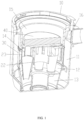
FIG. 1 is a sectional view of a separation structure for a dust cup of a vacuum cleaner according to an embodiment of the present disclosure. -
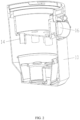
FIG. 2 is a sectional view of a main body of the separation structure according to an embodiment of the present disclosure. -
FIG. 3 is a perspective view of a separator of the separation structure according to an embodiment of the present disclosure. -
FIG. 4 is another perspective view of the separator of the separation structure according to an embodiment of the present disclosure. - For clearer and complete description to the technical schemes of the present disclosure, the present disclosure is described further with reference to the accompanying drawings.
- Referring to
FIGS. 1 to 4 , an embodiment of the present disclosure provides a separation structure for a dust cup of a vacuum cleaner. The separation structure includes amain body 10 and aseparator 20. Theseparator 20 is fixedly mounted in an internal space of themain body 10. The internal space of themain body 10 is divided by theseparator 20 into three chambers, i.e., a first chamber 11, asecond chamber 12, and athird chamber 13. Theseparator 20 is provided with athrough hole 21, anair intake portion 22, and a plurality ofsedimentation portions 23 communicated with theair intake portion 22. The plurality ofsedimentation portions 23 are arranged around theair intake portion 22. A length of theair intake portion 22 is smaller than a length of eachsedimentation portion 23. Theair intake portion 22 is communicated with thesecond chamber 12, thesedimentation portions 23 are communicated with thethird chamber 13, and the first chamber 11 is communicated with thesecond chamber 12 via the throughhole 21. - In this embodiment, the
air intake portion 22 is a circular tube. Theair intake portion 22 and thesedimentation portions 23 are both located within thesecond chamber 12. - In this embodiment, the
separator 20 of the separation structure has a simple structure, the length of theair intake portion 22 is short, a resistance of theair intake portion 22 to the air flow is very small, and the mixture of air and waste can travel a short distance from theair intake portion 22 to eachsedimentation portion 23. The length of theseparator 20 is reduced, so that the size of the dust cup adopting the separation structure is reduced, and a low-power motor is sufficient for driving the dust cup. - In the present embodiment, the
separator 20 is integrally formed without manual assembly, thereby reducing the production cost of the dust cup adopting the separation structure. - Further, a ratio of the length of each
sedimentation portion 23 to the length of theair intake portion 22 is in a range of 1.5 to 2.5. - Further, the separation structure further includes a
filter screen 30 arranged along a periphery of theseparator 20. Thefilter screen 30 covers the throughhole 21. - Further, the
main body 10 also has anair inlet 16 communicated with the first chamber 11. - Further, the
separator 20 is provided with a plurality ofventilation grooves 24, each of which corresponds to arespective sedimentation portions 23. Thesedimentation portions 23 are communicated with theair intake portion 22 through theventilation grooves 24. - Further, a ratio of a maximum inner diameter of the
air intake portion 22 to a maximum width of eachventilation groove 24 is in a range of 4.5 to 5.5. - In this embodiment, when the dust cup adopting the separation structure is driven by a motor, the mixture of air and waste enters the first chamber 11 through the
air inlet 16 and forms a rotating air flow, and a primary separation of the mixture of air and waste occurs with thefilter 30. Large particles of the waste are prevented from entering thesecond chamber 12 by thefilter 30, and gradually deposited at a bottom of the first chamber 11. The mixture of air and waste then enters theair intake portion 22 under the drive of the motor, and spirals up within theair intake portion 22 for a secondary separation, and a part of small particles of the waste is gradually deposited at a bottom of thesecond chamber 12. The mixture of air and waste then enters thesedimentation portions 23 through theventilation grooves 24 under the drive of the motor, and by this time, the air flow formed by the mixture of air and waste has a higher rotating speed for a tertiary separation. Another part of the small particles of the waste is gradually deposited at a bottom of thethird chamber 13 through thesedimentation portions 23, and by this time, most of the waste has been separated from the air. - In this embodiment, the
air inlet 16 is provided on a side surface of themain body 10, and a flow path of the mixture of air and waste from theair inlet 16 to eachsedimentation portion 23 can be shortened. - Further, each
sedimentation portion 23 includes acylindrical tube 25 and a conical tube 26 communicated with thecylindrical tube 25. A length of the conical tube 26 is greater than a length of thecylindrical tube 25. The conical tube 26 is communicated with thethird chamber 13, and thecylindrical tube 25 is communicated with theair intake portion 22 through arespective ventilation groove 24. - Further, a distance from a center of the
cylindrical tube 25 to a center of theair intake portion 22 is L, and a ratio of 2L to the maximum inner diameter of theair intake portion 22 is in a range of 1.8 to 2.5. - In this embodiment, when the dust cup adopting the separation structure is driven by a motor, the mixture of air and waste enters the first chamber 11 through the
air inlet 16 and forms a rotating air flow, and a primary separation of the mixture of air and waste occurs with thefilter 30. Large particles of the waste are prevented from entering thesecond chamber 12 by thefilter 30, and gradually deposited at a bottom of the first chamber 11. The mixture of air and waste then enters theair intake portion 22 under the drive of the motor, and spirals up within theair intake portion 22 for a secondary separation, and a part of small particles of the waste is gradually deposited at a bottom of thesecond chamber 12. The mixture of air and waste then enters thecylindrical tubes 25 through theventilation grooves 24 under the drive of the motor, and by this time, the air flow formed by the mixture of air and waste has a higher rotating speed for a tertiary separation. Another part of the small particles of the waste is gradually deposited at a bottom of thethird chamber 13 through the conical tubes 26, and by this time, most of the waste has been separated from the air. - Further, the
main body 10 is provided with a plurality ofair outlet tubes 14 each of which corresponds to arespective sedimentation portion 23. Eachair outlet tube 14 is received within a respectcylindrical tube 25. - Further, the separation structure further includes a
filter cotton 40. A recess is defined by themain body 10 to form afourth chamber 15. Theair outlet tubes 14 are communicated with thefourth chamber 15. Thefilter cotton 40 is received in thefourth chamber 15 and covers theair outlet tubes 14. - In this embodiment, when the dust cup adopting the separation structure is driven by a motor, the mixture of air and waste enters the first chamber 11 through the
air inlet 16 and forms a rotating air flow, and a primary separation of the mixture of air and waste occurs with thefilter 30. Large particles of the waste are prevented from entering thesecond chamber 12 by thefilter 30, and gradually deposited at a bottom of the first chamber 11. The mixture of air and waste then enters theair intake portion 22 under the drive of the motor, and spirals up within theair intake portion 22 for a secondary separation, and a part of small particles of the waste is gradually deposited at a bottom of thesecond chamber 12. The mixture of air and waste then enters thecylindrical tubes 25 through theventilation grooves 24 under the drive of the motor, and by this time, the air flow formed by the mixture of air and waste has a higher rotating speed for a tertiary separation. Another part of the small particles of the waste is gradually deposited at a bottom of thethird chamber 13 through the conical tubes 26. The mixture of air and waste then enters thefourth chamber 15 through theair outlet tubes 14 with driving of the motor, and the waste is finally separated from the air through thefilter cotton 40. The remaining small particles of the waste are adsorbed by thefilter cotton 40, thereby achieving complete separation of the waste from the air.
Claims (10)
- A separation structure for a dust cup of a vacuum cleaner, wherein the separation structure comprises a main body (10) and a separator (20), the separator (20) is fixedly mounted in an internal space of the main body (10), the internal space of the main body (10) is divided by the separator (20) into a first chamber (11), a second chamber (12) and a third chamber (13), the separator (20) is provided with a through hole (21), an air intake portion (22) and a plurality of sedimentation portions (23) communicated with the air intake portion (22), the plurality of sedimentation portions (23) are arranged around the air intake portion (22), a length of the air intake portion (22) is smaller than a length of each of the plurality of sedimentation portions (23), the air intake portion (22) is communicated with the second chamber (12), the plurality of sedimentation portions (23) are communicated with the third chamber (13), and the first chamber (11) is communicated with the second chamber (12) via the through hole (21), characterized in that
a lower portion of the second chamber (12) is separated from the third chamber (13) such that small particles of waste are deposited separately at bottoms of the second chamber (12) and the third chamber (13). - The separation structure according to claim 1, wherein a ratio of the length of each of the plurality of sedimentation portions (23) to the length of the air intake portion (22) is in a range of 1.5 to 2.5.
- The separation structure according to claim 1, further comprising a filter screen (30) arranged along a periphery of the separator (20) and covering the through hole (21).
- The separation structure according to claim 1, wherein the separator (20) is provided with a plurality of ventilation grooves (24), each of which corresponds to a respective one of the plurality of sedimentation portions (23), and the plurality of sedimentation portions (23) are communicated with the air intake portion (22) through the plurality of ventilation grooves (24).
- The separation structure according to claim 4, wherein each of the plurality of sedimentation portions (23) comprises a cylindrical tube (25) and a conical tube (26) communicated with the cylindrical tube (25), a length of the conical tube (26) is greater than a length of the cylindrical tube (25), the conical tube (26) is communicated with the third chamber (13), and the cylindrical tube (25) is communicated with the air intake portion (22) through a respective one of the plurality of ventilation grooves (24).
- The separation structure according to claim 5, wherein the main body (10) is further provided with a plurality of air outlet tubes (14), each of which corresponds to a respective one of the plurality of sedimentation portions (23) and is received within the cylindrical tube (25).
- The separation structure according to claim 6, further comprising a filter cotton (40), a recess is defined by the main body (10) to form a fourth chamber (15), the plurality of air outlet tubes (14) are communicated with the fourth chamber (15), and the filter cotton (40) is received in the fourth chamber (15) and covers the plurality of air outlet tubes (14).
- The separation structure according to claim 5, wherein a distance from a center of the cylindrical tube (25) to a center of the air intake portion (22) is L, and a ratio of 2L to a maximum inner diameter of the air intake portion (22) is in a range of 1.8 to 2.5.
- The separation structure according to claim 5, wherein a ratio of a maximum inner diameter of the air intake portion (22) to a maximum width of each of the plurality of ventilation grooves (24) is in a range of 4.5 to 5.5.
- The separation structure according to claim 1, wherein the main body (10) is further provided with an air inlet (16) communicated with the first chamber (11).
Applications Claiming Priority (2)
| Application Number | Priority Date | Filing Date | Title |
|---|---|---|---|
| CN202121353171.4U CN215383686U (en) | 2021-06-17 | 2021-06-17 | Separation structure of dust cup of dust collector |
| PCT/CN2021/132320 WO2022262196A1 (en) | 2021-06-17 | 2021-11-23 | Separation structure of dust cup of dust collector |
Publications (3)
| Publication Number | Publication Date |
|---|---|
| EP4129138A4 EP4129138A4 (en) | 2023-02-08 |
| EP4129138A1 EP4129138A1 (en) | 2023-02-08 |
| EP4129138B1 true EP4129138B1 (en) | 2024-08-28 |
Family
ID=84490613
Family Applications (1)
| Application Number | Title | Priority Date | Filing Date |
|---|---|---|---|
| EP21830309.7A Active EP4129138B1 (en) | 2021-06-17 | 2021-11-23 | Separation structure of dust cup of dust collector |
Country Status (3)
| Country | Link |
|---|---|
| US (1) | US20220400918A1 (en) |
| EP (1) | EP4129138B1 (en) |
| JP (1) | JP2023534563A (en) |
Families Citing this family (1)
| Publication number | Priority date | Publication date | Assignee | Title |
|---|---|---|---|---|
| USD995021S1 (en) * | 2020-09-14 | 2023-08-08 | Samsung Electronics Co., Ltd. | Dust canister for vacuum cleaner |
Family Cites Families (24)
| Publication number | Priority date | Publication date | Assignee | Title |
|---|---|---|---|---|
| US2372514A (en) * | 1941-08-29 | 1945-03-27 | Western Precipitation Corp | Multistage centrifugal separating apparatus |
| KR100536503B1 (en) * | 2003-09-09 | 2005-12-14 | 삼성광주전자 주식회사 | A cyclone separating apparatus and vacumm cleaner equipped whth such a device |
| KR100594587B1 (en) * | 2005-03-29 | 2006-06-30 | 삼성광주전자 주식회사 | Multi Cyclone Dust Collector |
| GB2426473B (en) * | 2005-05-27 | 2008-11-05 | Dyson Technology Ltd | Cyclonic separating apparatus |
| KR100667874B1 (en) * | 2005-10-10 | 2007-01-16 | 삼성광주전자 주식회사 | Multi Cyclone Dust Collector |
| KR100630952B1 (en) * | 2005-10-11 | 2006-10-04 | 삼성광주전자 주식회사 | Multi cyclone dust collector for vacuum cleaner and vacuum cleaner having same |
| US20070144116A1 (en) * | 2005-12-23 | 2007-06-28 | Samsung Electronics Co., Ltd. | Cyclonic cleaner |
| KR100767122B1 (en) * | 2006-02-24 | 2007-10-17 | 삼성광주전자 주식회사 | Cyclone dust collecting apparatus for vacuum cleaner |
| GB2440125A (en) * | 2006-07-18 | 2008-01-23 | Dyson Technology Ltd | Cyclonic separating apparatus |
| US7749292B2 (en) * | 2006-11-16 | 2010-07-06 | Suzhou Clean Bloom Electric Co., Ltd. | Cyclonic dust collecting apparatus |
| KR100783143B1 (en) * | 2007-02-05 | 2007-12-07 | 삼성광주전자 주식회사 | Cyclone Dust Collector for Vacuum Cleaner |
| GB2453949B (en) * | 2007-10-23 | 2012-03-28 | Hoover Ltd | Cyclonic separation apparatus |
| US7879142B2 (en) * | 2008-01-16 | 2011-02-01 | Samsung Gwangju Electronics Co., Ltd. | Cyclone dust collector and vacuum cleaner |
| US9962052B2 (en) * | 2011-03-04 | 2018-05-08 | Omachron Intellectual Property Inc. | Surface cleaning apparatus |
| US11534043B2 (en) * | 2011-03-04 | 2022-12-27 | Omachron Intellectual Property Inc. | Surface cleaning apparatus |
| EP2581020A1 (en) * | 2011-10-12 | 2013-04-17 | Black & Decker Inc. | Cyclonic separation apparatus |
| US8973215B2 (en) * | 2012-07-18 | 2015-03-10 | Techtronic Floor Care Technology Limited | Cyclonic vacuum cleaner and dirt separator |
| GB2504776B (en) * | 2012-08-10 | 2015-05-27 | Vax Ltd | Dust separation in vacuum cleaners |
| GB2510359B (en) * | 2013-01-31 | 2015-04-08 | Dyson Technology Ltd | Dirt Separator for a Vacuum Cleaner |
| CN203468516U (en) * | 2013-08-31 | 2014-03-12 | 卓力电器集团有限公司 | Tertiary cyclone vacuum cleaner |
| GB2522659B (en) * | 2014-01-31 | 2016-04-06 | Dyson Technology Ltd | Separating apparatus in a vacuum cleaner |
| KR101854681B1 (en) * | 2016-08-25 | 2018-06-08 | 엘지전자 주식회사 | Dust collector and vacuum cleaner having the same |
| GB2598506B (en) * | 2017-06-19 | 2022-06-08 | Techtronic Floor Care Tech Ltd | A dirt separation device |
| KR102080013B1 (en) * | 2018-08-29 | 2020-02-21 | 삼성전자주식회사 | Multi-cyclone dust collecting apparatus and vaccum cleaner having the same |
-
2021
- 2021-11-23 JP JP2022502565A patent/JP2023534563A/en active Pending
- 2021-11-23 EP EP21830309.7A patent/EP4129138B1/en active Active
- 2021-12-30 US US17/566,619 patent/US20220400918A1/en not_active Abandoned
Also Published As
| Publication number | Publication date |
|---|---|
| JP2023534563A (en) | 2023-08-10 |
| US20220400918A1 (en) | 2022-12-22 |
| EP4129138A1 (en) | 2023-02-08 |
Similar Documents
| Publication | Publication Date | Title |
|---|---|---|
| US10639652B2 (en) | Dust collector and cleaner having the same | |
| CN209437158U (en) | dust collector | |
| US7815702B2 (en) | Multi cyclone collector | |
| CN112138879B (en) | A kind of cyclone separation dust removal method | |
| US11759073B2 (en) | Multi-cyclone dust collecting device and vacuum cleaner including same | |
| US10632478B2 (en) | Dust collector and cleaner having the same | |
| CN209996198U (en) | Dust collector | |
| GB2490270A (en) | Cyclone separator device and electric cleaner | |
| CN112043202B (en) | A cyclone separator and cleaning equipment | |
| US10799887B2 (en) | Dust collector and cleaner having the same | |
| US11147423B2 (en) | Dust collector and cleaner having the same | |
| KR102776618B1 (en) | Dust collector and vacuum cleaner having the same | |
| WO2021004040A1 (en) | Separator, dust cup assembly and dust suction device | |
| CN112122019B (en) | Cyclone separation device and cleaning equipment | |
| EP4129138A1 (en) | Separation structure of dust cup of dust collector | |
| CN107898383B (en) | Dust cup and vacuum cleaner having the same | |
| KR100577679B1 (en) | Cyclone dust collector and vacuum cleaner comprising same | |
| CN217852707U (en) | Cyclone separator and surface cleaning device | |
| EP1679026B1 (en) | Apparatus for collecting dust and vacuum cleaner having the same | |
| CN215383686U (en) | Separation structure of dust cup of dust collector | |
| KR102658396B1 (en) | Dust collector and vacuum cleaner having the same | |
| CN222931022U (en) | Multi-inlet cyclone cone structure beneficial to acceleration of airflow | |
| CN213348108U (en) | Downstream cyclone separation assembly and cleaning equipment | |
| CN112773281B (en) | Multiphase fluid mixing, cleaning, gas-sewage separating and integrating structure | |
| KR20180035764A (en) | Dust collector and vacuum cleaner having the same |
Legal Events
| Date | Code | Title | Description |
|---|---|---|---|
| STAA | Information on the status of an ep patent application or granted ep patent |
Free format text: STATUS: UNKNOWN |
|
| STAA | Information on the status of an ep patent application or granted ep patent |
Free format text: STATUS: THE INTERNATIONAL PUBLICATION HAS BEEN MADE |
|
| PUAI | Public reference made under article 153(3) epc to a published international application that has entered the european phase |
Free format text: ORIGINAL CODE: 0009012 |
|
| STAA | Information on the status of an ep patent application or granted ep patent |
Free format text: STATUS: REQUEST FOR EXAMINATION WAS MADE |
|
| 17P | Request for examination filed |
Effective date: 20220323 |
|
| A4 | Supplementary search report drawn up and despatched |
Effective date: 20221209 |
|
| AK | Designated contracting states |
Kind code of ref document: A1 Designated state(s): AL AT BE BG CH CY CZ DE DK EE ES FI FR GB GR HR HU IE IS IT LI LT LU LV MC MK MT NL NO PL PT RO RS SE SI SK SM TR |
|
| GRAP | Despatch of communication of intention to grant a patent |
Free format text: ORIGINAL CODE: EPIDOSNIGR1 |
|
| STAA | Information on the status of an ep patent application or granted ep patent |
Free format text: STATUS: GRANT OF PATENT IS INTENDED |
|
| DAV | Request for validation of the european patent (deleted) | ||
| DAX | Request for extension of the european patent (deleted) | ||
| INTG | Intention to grant announced |
Effective date: 20240326 |
|
| GRAS | Grant fee paid |
Free format text: ORIGINAL CODE: EPIDOSNIGR3 |
|
| GRAA | (expected) grant |
Free format text: ORIGINAL CODE: 0009210 |
|
| STAA | Information on the status of an ep patent application or granted ep patent |
Free format text: STATUS: THE PATENT HAS BEEN GRANTED |
|
| AK | Designated contracting states |
Kind code of ref document: B1 Designated state(s): AL AT BE BG CH CY CZ DE DK EE ES FI FR GB GR HR HU IE IS IT LI LT LU LV MC MK MT NL NO PL PT RO RS SE SI SK SM TR |
|
| REG | Reference to a national code |
Ref country code: CH Ref legal event code: EP |
|
| REG | Reference to a national code |
Ref country code: DE Ref legal event code: R096 Ref document number: 602021018084 Country of ref document: DE |
|
| REG | Reference to a national code |
Ref country code: IE Ref legal event code: FG4D |
|
| REG | Reference to a national code |
Ref country code: LT Ref legal event code: MG9D |
|
| PGFP | Annual fee paid to national office [announced via postgrant information from national office to epo] |
Ref country code: DE Payment date: 20241121 Year of fee payment: 4 |
|
| PG25 | Lapsed in a contracting state [announced via postgrant information from national office to epo] |
Ref country code: NO Free format text: LAPSE BECAUSE OF FAILURE TO SUBMIT A TRANSLATION OF THE DESCRIPTION OR TO PAY THE FEE WITHIN THE PRESCRIBED TIME-LIMIT Effective date: 20241128 |
|
| REG | Reference to a national code |
Ref country code: AT Ref legal event code: MK05 Ref document number: 1717012 Country of ref document: AT Kind code of ref document: T Effective date: 20240828 |
|
| PG25 | Lapsed in a contracting state [announced via postgrant information from national office to epo] |
Ref country code: NL Free format text: LAPSE BECAUSE OF FAILURE TO SUBMIT A TRANSLATION OF THE DESCRIPTION OR TO PAY THE FEE WITHIN THE PRESCRIBED TIME-LIMIT Effective date: 20240828 Ref country code: GR Free format text: LAPSE BECAUSE OF FAILURE TO SUBMIT A TRANSLATION OF THE DESCRIPTION OR TO PAY THE FEE WITHIN THE PRESCRIBED TIME-LIMIT Effective date: 20241129 Ref country code: PL Free format text: LAPSE BECAUSE OF FAILURE TO SUBMIT A TRANSLATION OF THE DESCRIPTION OR TO PAY THE FEE WITHIN THE PRESCRIBED TIME-LIMIT Effective date: 20240828 Ref country code: FI Free format text: LAPSE BECAUSE OF FAILURE TO SUBMIT A TRANSLATION OF THE DESCRIPTION OR TO PAY THE FEE WITHIN THE PRESCRIBED TIME-LIMIT Effective date: 20240828 Ref country code: PT Free format text: LAPSE BECAUSE OF FAILURE TO SUBMIT A TRANSLATION OF THE DESCRIPTION OR TO PAY THE FEE WITHIN THE PRESCRIBED TIME-LIMIT Effective date: 20241230 |
|
| PG25 | Lapsed in a contracting state [announced via postgrant information from national office to epo] |
Ref country code: BG Free format text: LAPSE BECAUSE OF FAILURE TO SUBMIT A TRANSLATION OF THE DESCRIPTION OR TO PAY THE FEE WITHIN THE PRESCRIBED TIME-LIMIT Effective date: 20240828 |
|
| PGFP | Annual fee paid to national office [announced via postgrant information from national office to epo] |
Ref country code: FR Payment date: 20241128 Year of fee payment: 4 |
|
| PG25 | Lapsed in a contracting state [announced via postgrant information from national office to epo] |
Ref country code: LV Free format text: LAPSE BECAUSE OF FAILURE TO SUBMIT A TRANSLATION OF THE DESCRIPTION OR TO PAY THE FEE WITHIN THE PRESCRIBED TIME-LIMIT Effective date: 20240828 |
|
| REG | Reference to a national code |
Ref country code: NL Ref legal event code: MP Effective date: 20240828 |
|
| PG25 | Lapsed in a contracting state [announced via postgrant information from national office to epo] |
Ref country code: AT Free format text: LAPSE BECAUSE OF FAILURE TO SUBMIT A TRANSLATION OF THE DESCRIPTION OR TO PAY THE FEE WITHIN THE PRESCRIBED TIME-LIMIT Effective date: 20240828 Ref country code: IS Free format text: LAPSE BECAUSE OF FAILURE TO SUBMIT A TRANSLATION OF THE DESCRIPTION OR TO PAY THE FEE WITHIN THE PRESCRIBED TIME-LIMIT Effective date: 20241228 |
|
| PG25 | Lapsed in a contracting state [announced via postgrant information from national office to epo] |
Ref country code: HR Free format text: LAPSE BECAUSE OF FAILURE TO SUBMIT A TRANSLATION OF THE DESCRIPTION OR TO PAY THE FEE WITHIN THE PRESCRIBED TIME-LIMIT Effective date: 20240828 |
|
| PG25 | Lapsed in a contracting state [announced via postgrant information from national office to epo] |
Ref country code: ES Free format text: LAPSE BECAUSE OF FAILURE TO SUBMIT A TRANSLATION OF THE DESCRIPTION OR TO PAY THE FEE WITHIN THE PRESCRIBED TIME-LIMIT Effective date: 20240828 Ref country code: RS Free format text: LAPSE BECAUSE OF FAILURE TO SUBMIT A TRANSLATION OF THE DESCRIPTION OR TO PAY THE FEE WITHIN THE PRESCRIBED TIME-LIMIT Effective date: 20241128 |
|
| PG25 | Lapsed in a contracting state [announced via postgrant information from national office to epo] |
Ref country code: RS Free format text: LAPSE BECAUSE OF FAILURE TO SUBMIT A TRANSLATION OF THE DESCRIPTION OR TO PAY THE FEE WITHIN THE PRESCRIBED TIME-LIMIT Effective date: 20241128 Ref country code: PT Free format text: LAPSE BECAUSE OF FAILURE TO SUBMIT A TRANSLATION OF THE DESCRIPTION OR TO PAY THE FEE WITHIN THE PRESCRIBED TIME-LIMIT Effective date: 20241230 Ref country code: PL Free format text: LAPSE BECAUSE OF FAILURE TO SUBMIT A TRANSLATION OF THE DESCRIPTION OR TO PAY THE FEE WITHIN THE PRESCRIBED TIME-LIMIT Effective date: 20240828 Ref country code: NO Free format text: LAPSE BECAUSE OF FAILURE TO SUBMIT A TRANSLATION OF THE DESCRIPTION OR TO PAY THE FEE WITHIN THE PRESCRIBED TIME-LIMIT Effective date: 20241128 Ref country code: NL Free format text: LAPSE BECAUSE OF FAILURE TO SUBMIT A TRANSLATION OF THE DESCRIPTION OR TO PAY THE FEE WITHIN THE PRESCRIBED TIME-LIMIT Effective date: 20240828 Ref country code: LV Free format text: LAPSE BECAUSE OF FAILURE TO SUBMIT A TRANSLATION OF THE DESCRIPTION OR TO PAY THE FEE WITHIN THE PRESCRIBED TIME-LIMIT Effective date: 20240828 Ref country code: IS Free format text: LAPSE BECAUSE OF FAILURE TO SUBMIT A TRANSLATION OF THE DESCRIPTION OR TO PAY THE FEE WITHIN THE PRESCRIBED TIME-LIMIT Effective date: 20241228 Ref country code: HR Free format text: LAPSE BECAUSE OF FAILURE TO SUBMIT A TRANSLATION OF THE DESCRIPTION OR TO PAY THE FEE WITHIN THE PRESCRIBED TIME-LIMIT Effective date: 20240828 Ref country code: GR Free format text: LAPSE BECAUSE OF FAILURE TO SUBMIT A TRANSLATION OF THE DESCRIPTION OR TO PAY THE FEE WITHIN THE PRESCRIBED TIME-LIMIT Effective date: 20241129 Ref country code: FI Free format text: LAPSE BECAUSE OF FAILURE TO SUBMIT A TRANSLATION OF THE DESCRIPTION OR TO PAY THE FEE WITHIN THE PRESCRIBED TIME-LIMIT Effective date: 20240828 Ref country code: ES Free format text: LAPSE BECAUSE OF FAILURE TO SUBMIT A TRANSLATION OF THE DESCRIPTION OR TO PAY THE FEE WITHIN THE PRESCRIBED TIME-LIMIT Effective date: 20240828 Ref country code: BG Free format text: LAPSE BECAUSE OF FAILURE TO SUBMIT A TRANSLATION OF THE DESCRIPTION OR TO PAY THE FEE WITHIN THE PRESCRIBED TIME-LIMIT Effective date: 20240828 Ref country code: AT Free format text: LAPSE BECAUSE OF FAILURE TO SUBMIT A TRANSLATION OF THE DESCRIPTION OR TO PAY THE FEE WITHIN THE PRESCRIBED TIME-LIMIT Effective date: 20240828 |
|
| PG25 | Lapsed in a contracting state [announced via postgrant information from national office to epo] |
Ref country code: RO Free format text: LAPSE BECAUSE OF FAILURE TO SUBMIT A TRANSLATION OF THE DESCRIPTION OR TO PAY THE FEE WITHIN THE PRESCRIBED TIME-LIMIT Effective date: 20240828 Ref country code: DK Free format text: LAPSE BECAUSE OF FAILURE TO SUBMIT A TRANSLATION OF THE DESCRIPTION OR TO PAY THE FEE WITHIN THE PRESCRIBED TIME-LIMIT Effective date: 20240828 Ref country code: SM Free format text: LAPSE BECAUSE OF FAILURE TO SUBMIT A TRANSLATION OF THE DESCRIPTION OR TO PAY THE FEE WITHIN THE PRESCRIBED TIME-LIMIT Effective date: 20240828 |
|
| PG25 | Lapsed in a contracting state [announced via postgrant information from national office to epo] |
Ref country code: EE Free format text: LAPSE BECAUSE OF FAILURE TO SUBMIT A TRANSLATION OF THE DESCRIPTION OR TO PAY THE FEE WITHIN THE PRESCRIBED TIME-LIMIT Effective date: 20240828 |
|
| PG25 | Lapsed in a contracting state [announced via postgrant information from national office to epo] |
Ref country code: CZ Free format text: LAPSE BECAUSE OF FAILURE TO SUBMIT A TRANSLATION OF THE DESCRIPTION OR TO PAY THE FEE WITHIN THE PRESCRIBED TIME-LIMIT Effective date: 20240828 |
|
| PG25 | Lapsed in a contracting state [announced via postgrant information from national office to epo] |
Ref country code: IT Free format text: LAPSE BECAUSE OF FAILURE TO SUBMIT A TRANSLATION OF THE DESCRIPTION OR TO PAY THE FEE WITHIN THE PRESCRIBED TIME-LIMIT Effective date: 20240828 Ref country code: SK Free format text: LAPSE BECAUSE OF FAILURE TO SUBMIT A TRANSLATION OF THE DESCRIPTION OR TO PAY THE FEE WITHIN THE PRESCRIBED TIME-LIMIT Effective date: 20240828 |
|
| REG | Reference to a national code |
Ref country code: DE Ref legal event code: R097 Ref document number: 602021018084 Country of ref document: DE |
|
| REG | Reference to a national code |
Ref country code: CH Ref legal event code: PL |
|
| PLBE | No opposition filed within time limit |
Free format text: ORIGINAL CODE: 0009261 |
|
| STAA | Information on the status of an ep patent application or granted ep patent |
Free format text: STATUS: NO OPPOSITION FILED WITHIN TIME LIMIT |
|
| PG25 | Lapsed in a contracting state [announced via postgrant information from national office to epo] |
Ref country code: MC Free format text: LAPSE BECAUSE OF FAILURE TO SUBMIT A TRANSLATION OF THE DESCRIPTION OR TO PAY THE FEE WITHIN THE PRESCRIBED TIME-LIMIT Effective date: 20240828 |
|
| PG25 | Lapsed in a contracting state [announced via postgrant information from national office to epo] |
Ref country code: LU Free format text: LAPSE BECAUSE OF NON-PAYMENT OF DUE FEES Effective date: 20241123 |
|
| REG | Reference to a national code |
Ref country code: CH Ref legal event code: PL |
|
| PG25 | Lapsed in a contracting state [announced via postgrant information from national office to epo] |
Ref country code: CH Free format text: LAPSE BECAUSE OF NON-PAYMENT OF DUE FEES Effective date: 20241130 |
|
| 26N | No opposition filed |
Effective date: 20250530 |
|
| REG | Reference to a national code |
Ref country code: BE Ref legal event code: MM Effective date: 20241130 |
|
| PG25 | Lapsed in a contracting state [announced via postgrant information from national office to epo] |
Ref country code: SE Free format text: LAPSE BECAUSE OF FAILURE TO SUBMIT A TRANSLATION OF THE DESCRIPTION OR TO PAY THE FEE WITHIN THE PRESCRIBED TIME-LIMIT Effective date: 20240828 |
|
| PG25 | Lapsed in a contracting state [announced via postgrant information from national office to epo] |
Ref country code: BE Free format text: LAPSE BECAUSE OF NON-PAYMENT OF DUE FEES Effective date: 20241130 |
|
| PG25 | Lapsed in a contracting state [announced via postgrant information from national office to epo] |
Ref country code: IE Free format text: LAPSE BECAUSE OF NON-PAYMENT OF DUE FEES Effective date: 20241123 |
|
| PG25 | Lapsed in a contracting state [announced via postgrant information from national office to epo] |
Ref country code: HU Free format text: LAPSE BECAUSE OF FAILURE TO SUBMIT A TRANSLATION OF THE DESCRIPTION OR TO PAY THE FEE WITHIN THE PRESCRIBED TIME-LIMIT; INVALID AB INITIO Effective date: 20211123 |
|
| PG25 | Lapsed in a contracting state [announced via postgrant information from national office to epo] |
Ref country code: CY Free format text: LAPSE BECAUSE OF FAILURE TO SUBMIT A TRANSLATION OF THE DESCRIPTION OR TO PAY THE FEE WITHIN THE PRESCRIBED TIME-LIMIT; INVALID AB INITIO Effective date: 20211123 |