EP4129132A1 - Axial adapter for kitchen appliance - Google Patents
Axial adapter for kitchen appliance Download PDFInfo
- Publication number
- EP4129132A1 EP4129132A1 EP21189900.0A EP21189900A EP4129132A1 EP 4129132 A1 EP4129132 A1 EP 4129132A1 EP 21189900 A EP21189900 A EP 21189900A EP 4129132 A1 EP4129132 A1 EP 4129132A1
- Authority
- EP
- European Patent Office
- Prior art keywords
- adapter
- clutch
- bushing
- kitchen appliance
- housing
- Prior art date
- Legal status (The legal status is an assumption and is not a legal conclusion. Google has not performed a legal analysis and makes no representation as to the accuracy of the status listed.)
- Granted
Links
Images


Classifications
-
- A—HUMAN NECESSITIES
- A47—FURNITURE; DOMESTIC ARTICLES OR APPLIANCES; COFFEE MILLS; SPICE MILLS; SUCTION CLEANERS IN GENERAL
- A47J—KITCHEN EQUIPMENT; COFFEE MILLS; SPICE MILLS; APPARATUS FOR MAKING BEVERAGES
- A47J43/00—Implements for preparing or holding food, not provided for in other groups of this subclass
- A47J43/04—Machines for domestic use not covered elsewhere, e.g. for grinding, mixing, stirring, kneading, emulsifying, whipping or beating foodstuffs, e.g. power-driven
- A47J43/07—Parts or details, e.g. mixing tools, whipping tools
-
- A—HUMAN NECESSITIES
- A47—FURNITURE; DOMESTIC ARTICLES OR APPLIANCES; COFFEE MILLS; SPICE MILLS; SUCTION CLEANERS IN GENERAL
- A47J—KITCHEN EQUIPMENT; COFFEE MILLS; SPICE MILLS; APPARATUS FOR MAKING BEVERAGES
- A47J43/00—Implements for preparing or holding food, not provided for in other groups of this subclass
- A47J43/04—Machines for domestic use not covered elsewhere, e.g. for grinding, mixing, stirring, kneading, emulsifying, whipping or beating foodstuffs, e.g. power-driven
- A47J43/07—Parts or details, e.g. mixing tools, whipping tools
- A47J43/08—Driving mechanisms
Definitions
- the present invention concerns an axial adapter for a kitchen appliance driven by an electric motor, in particular a household appliance, wherein the axial adapter is adapted to be mounted to the kitchen appliance and adapted to carry an attachment of the kitchen appliance, wherein the adapter has a housing which is opened at its opposite end faces and inside which a clutch is positioned rotatably in order to transfer a rotation of a motor output shaft and a motor torque to the attachment.
- Adapters are generally used if an attachment requires a special mounting fixture as it does not fit to an integrally standard mounting fixture provided by the electric kitchen appliance.
- Exemplary attachments are meat mincers and pasta makers.
- An inventive axial adapter for a kitchen appliance driven by an electric motor adapted to be mounted to the kitchen appliance and adapted to carry an attachment of the kitchen appliance has a housing which is opened at its opposite end faces and a clutch which is positioned rotatably inside the housing in order to transfer a rotation of a motor output shaft and a motor torque to the attachment.
- the clutch is in rotatable form-fit engagement with a bushing which is firmly clamped between a first part of the adapter and a second part of the adapter opposite to the first part.
- the adapter has a modular design, the parts are fixed to each other.
- the adapter parts can be made of plastics material or, in particular the housing can be made of any other materials such as brushed aluminium or stainless steel
- the first part is a releasable cup-like insert which is fixed within the housing by screws or snap connection and which has an opening for the clutch.
- the first part can be removed and the bushing can be disassembled easily facilitating the cleaning of the adapter and its part.
- the second part is preferably an integral pipe-like portion of the housing.
- the integration of the second part reduces the number of parts necessary for the adapter.
- the tubular shape creates an opening of the housing for the clutch and for the attachment.
- the first part can have a form-fit structure on its inner side adapted to act together with a counter form-fit portion of the kitchen appliance.
- the form-fit structure is a bayonet system.
- different form-fit elements can be combined with the housing, so that the adapter can be adapted to the respective kitchen appliance.
- the second part can have a form-fit structure at its outer surface adapted to act together with a counter form-fit structure of the attachment.
- the form-fit structure is a bayonet system.
- the form-fit engagement of the clutch with the bushing can be done by an integral ring at an outer surface of the clutch and by a counter groove at an inner surface of the bushing.
- the groove and the ring Preferably have a semi-circular cross-section.
- Such groove and ring are easy to manufacture and sharp edges or corners are avoided.
- such a form-fit engagement enables a simple and good fit of the clutch and the bushing (the clutch is fixed axially only by means of engagement of the ring in the groove). Thereby a tolerance problem of many parts fitting together can be avoided. Only tolerances of the ring and the groove have to be taken into account. This provides for a very short tolerance chain.
- the bushing is made of two semi-circular elements. In order to avoid a misalignment of the bushing parts to each other, they can have respective recesses and protrusions acting as form-fit elements as well.
- the bushing has a radial inner portion and radial outer portion, whereas the radial inner portion is in contact with the second part of the adapter and the radial outer part is in contact with the first part of the adapter.
- those area of the bushing is broadened at which the motor torque is transferred in the clutch.
- the clutch can have a respective design with a radial outer portion and a radial inner portion.
- the clutch can have a longer axial extension than the bushing in order to provide space for the mounting fixtures of the kitchen appliance and the attachment.
- the adapter can have a retaining means adapted to be activated before the adapter can be removed from the kitchen appliance and a release means adapted to be activated before the attachment can be removed from the adapter.
- the bushing comprises at least one recess adapted to communicate with a projection on the inside of the housing.
- the effect is that the bushing cannot rotate inside the housing.
- the projections can comprise thread holes for screws adapted to releasably connect the insert to the housing.
- a preferred axial adapter 1 adapted to be mounted to a kitchen appliance (not shown) and adapted to carry an attachment (not shown) of the kitchen appliance, has housing 2 having a longitudinal axis x, a circumferential wall 4 with one radial inner end 6 and an opposite radial outer end 8. Both end faces are opened so that the housing 2 is opened on both sides axially.
- the radial outer end 8 is adapted to be directed to the kitchen appliance and the radial inner end 6 is adapted to be directed to the attachment of the kitchen appliance.
- parts of the adapter 1 are arranged which are required to transfer a rotation of a motor output shaft and a motor torque of an electric motor of the kitchen appliance to the attachment.
- the parts are in particular a clutch 12, a bushing 14, a cup-like insert 16 (first part of the adapter 1) and a tubular part 18 (second part of the adapter 1), which will be explained in more detail with reference to figures 3 and 4 .
- the clutch 12 is positioned rotatably on the longitudinal axis x of the housing 2 and held in place by the bushing 14.
- the clutch 12 has a radial outer portion 20 and an opposite radial inner portion 22.
- the radial inner portion 22 has a greater axial extension than the radial outer portion 20.
- Both portions 20, 22 comprise an inner form-fit structure 24, 26 ( figure 3 ) in order to receive a corresponding form-fit structure of a motor shaft coupling element and of an attachment coupling element, respectively.
- the radial outer portion 20 is adapted to act together with the corresponding form-fit structure of the motor shaft coupling element and the radial inner portion 22 is adapted to act together with the corresponding form-fit structure of the attachment coupling element.
- annular ring 28 On an outer surface of the radial inner portion 22 close to the radial outer portion 20, preferably in or close to the axial centre of the clutch 12, an annular ring 28 is positioned.
- the annular ring 28 acts as a form-fit element and is in engagement with an annular groove 30 on an inner surface of the bushing 14.
- the annular ring 28 and the corresponding grove 30 have a semi-circular shape. Due to the form-fit engagement caused by the ring 28 and the groove 30, the clutch 12 is fixed axially inside the brushing 14.
- the annular ring 28 and the groove 30 are designed in such a way that the clutch 12 is in surface contact with bushing 14, that means that no annular gap is provided between the clutch 12 and the bushing 14 surrounding the clutch 12 ( figure 3 ).
- the clutch 12 and the bushing 14 are made of an adequate material, such as plastics materials.
- the bushing 14 has a radial inner portion 34 and radial outer portion 36, wherein the radial inner portion 34 is in contact with the cup-like insert 16 of the adapter 1 and the radial outer portion 36 is in contact with the tubular part 18 of the adapter 1. In particular, the bushing 14 is clamped axially between the cup-like insert 16 and the tubular part 18.
- the bushing 14 is made of two semi-circular elements 14a, 14b which allows the assembling of clutch 12 and the bushing 14. In order to self-align the two semi-circular elements 14a,14b on their contact surfaces, corresponding form-fit elements 38, 40 are provided. Both radial portions 34, 36 of the bushing 14 are shorter than the radial portions 20, 22 of the clutch 12.
- the cup-like insert 16 has an opening 42 at its bottom side in order to receive the radial outer portion 20 of the clutch 12.
- the opening 42 is surrounded by an annular protrusion 44 acting as counter-bearing (abutment) for the bushing 14.
- the opening 42 has such an inner diameter that an annular gap 46 ( figure 3 ) is provided to the radial outer portion 20 of the clutch 12, avoiding any friction between these parts when the clutch 12 is rotating.
- the insert 16 is releasably connected to the housing 2 by means of screws 48 or a snap-connection (not shown).
- the used screws 48 pass through holes 50 in an annular bottom ring surrounding the opening 42 and are in engagement with respective thread holes of the housing 2 (not shown).
- the bushing 14 is clamped between the insert 16 and the tubular part 18.
- the insert 16 On its inner surface, the insert 16 has a form-fit structure 52 in order to be attached to a correspondent form-fit structure on the kitchen appliance.
- the form-fit structure 52 is designed as a bayonet connection.
- the insert 16 is preferably made of plastics materials.
- the tubular part 18 of the adapter 1 is formed integrally with the housing 2.
- One axial end 54 of the tubular part 18 is positioned inside the housing 2 and acts as counter-bearing (abutment) for the bushing 14. Therefore, the axial inner end 54 has the same outer diameter as the radial inner portion 34 of the bushing 14.
- An inner diameter of the tubular part 18 is reduced compared with an inner diameter of the radial inner portion 34 of the bushing 14 at a whole, in order to provide an annular gap 56 ( figure 3 ), thus avoiding any friction between the radial inner portion 22 of the clutch 12 and the tubular part 18 when the clutch 12 is rotating.
- the tubular part and the housing itself can be made of plastics materials or of any other adequate materials such as brushed aluminium or stainless steel.
- a form-fit structure 60 is provided adapted to receive a corresponding form-fit structure of the attachment to be attached.
- the form-fit structure 60 is designed as a bayonet connection.
- the adapter 1 has to on its both ends 6, 8 a form-fit structure, in particular bayonet systems.
- a retaining means 62 adapted to be activated before the adapter 1 can be removed from the kitchen appliance.
- the retaining means 62 is a kind of known lever which is pivotable arranged on a pin 63 orientated parallel to the longitudinal axis x of the housing and which has a nose 64 adapted to be in engagement with a corresponding recess of the kitchen appliance.
- a release means 66 adapted to be activated before the attachment can be removed from the adapter is provided.
- the release means 66 has a triangular body with an axial pin 68 positioned in a corresponding recess 70 of the housing 2 and biased by a spring 72 in axial direction.
- FIGS. 3 and 4 four rectangular bodies 74 are illustrated which are set in place in corresponding rectangular openings 76 of the cup-like insert 16.
- the rectangular bodies 74 can act as guiding means when attaching the adapter 1 to the kitchen appliance.
- Figures 5 and 6 depict the adapter 1 with the bushing 14 comprising at least one recess 14c, preferably four, adapted to communicate with a corresponding projection 77 on the inside of the housing 2, more specifically of the circumferential wall 4.
- the recess 14c is shown also in figure 4 .
- Assembling of the adapter 1 is done by lying the two semi-circular elements 14a, 14b around the clutch 12 such that the semi-circular elements 14a, 14b are aligned to each other and that the annular ring 28 enters the groove 30.
- the clutch-bushing-arrangement is positioned inside the housing, wherein the radial inner portion 22 of the clutch 12 is inserted into the tubular part 18.
- the cup-like insert 16 is positioned in the housing 2 such that the radial outer portion 20 of the clutch 12 passes through the opening 42.
- the screws 48 are tightened and the bushing 14 is clamped axially between the axial inner portion 54 of the tubular part 18 and the annular protrusion 44 of the insert 16.
- an axial adapter 1 for a kitchen appliance driven by an electric motor adapted to be mounted to the kitchen appliance and adapted to carry an attachment of the kitchen appliance
- the adapter 1 has a housing 2 which is opened at its opposite end faces inside which a clutch 12 is positioned rotatably in order to transfer a rotation of a motor output shaft and a motor torque to the attachment, wherein the clutch 12 is in rotatable form-fit engagement with a bushing 14 which is firmly clamped between a first part 16 of the adapter 1 and a second part 18 of the adapter 1 opposite to the first adapter part 16.
Landscapes
- Engineering & Computer Science (AREA)
- Mechanical Engineering (AREA)
- Food Science & Technology (AREA)
- Food-Manufacturing Devices (AREA)
Abstract
Description
- The present invention concerns an axial adapter for a kitchen appliance driven by an electric motor, in particular a household appliance, wherein the axial adapter is adapted to be mounted to the kitchen appliance and adapted to carry an attachment of the kitchen appliance, wherein the adapter has a housing which is opened at its opposite end faces and inside which a clutch is positioned rotatably in order to transfer a rotation of a motor output shaft and a motor torque to the attachment.
- Adapters are generally used if an attachment requires a special mounting fixture as it does not fit to an integrally standard mounting fixture provided by the electric kitchen appliance. Exemplary attachments are meat mincers and pasta makers. In order to simplify the handling of the adapters, it is recommended to have such an adapter design that every single part of the adapter should be held in place in the housing, independent of the orientation of the adapter. In other words, unintentional dissasembling (a part can fall down such as a clutch) should be prevented when the adapter is removed from the kitchen appliance and put upside down.
- It is an object of the present invention to provide such an axial adapter design that unintentional loss of a part, in particular of a clutch, is prevented.
- The object is achieved by an axial adapter according to features of
claim 1. Advantageous embodiments are disclosed in the dependent claims, the description and the figures. - An inventive axial adapter for a kitchen appliance driven by an electric motor, adapted to be mounted to the kitchen appliance and adapted to carry an attachment of the kitchen appliance has a housing which is opened at its opposite end faces and a clutch which is positioned rotatably inside the housing in order to transfer a rotation of a motor output shaft and a motor torque to the attachment. According to the invention, the clutch is in rotatable form-fit engagement with a bushing which is firmly clamped between a first part of the adapter and a second part of the adapter opposite to the first part.
- Due to the form-fit engagement with the bushing in combination with the fixed arrangement of the bushing inside the housing, an unintentional loss of the clutch and of the bushing itself is prevented. Although the adapter has a modular design, the parts are fixed to each other. The adapter parts can be made of plastics material or, in particular the housing can be made of any other materials such as brushed aluminium or stainless steel
- Preferably, the first part is a releasable cup-like insert which is fixed within the housing by screws or snap connection and which has an opening for the clutch. By means of this, the first part can be removed and the bushing can be disassembled easily facilitating the cleaning of the adapter and its part.
- The second part is preferably an integral pipe-like portion of the housing. The integration of the second part reduces the number of parts necessary for the adapter. The tubular shape creates an opening of the housing for the clutch and for the attachment.
- The handling of the adapter can be further facilitated if it can be attached to and detached from the kitchen appliance without the use of tools. Therefore, the first part can have a form-fit structure on its inner side adapted to act together with a counter form-fit portion of the kitchen appliance. Preferably, the form-fit structure is a bayonet system. In addition to the releasable mounting of the first part in the housing, different form-fit elements can be combined with the housing, so that the adapter can be adapted to the respective kitchen appliance.
- In order to facilitate the connecting and removing of the attachment to the adapter, the second part can have a form-fit structure at its outer surface adapted to act together with a counter form-fit structure of the attachment. Preferably, the form-fit structure is a bayonet system.
- The form-fit engagement of the clutch with the bushing can be done by an integral ring at an outer surface of the clutch and by a counter groove at an inner surface of the bushing. Preferably the groove and the ring have a semi-circular cross-section. Such groove and ring are easy to manufacture and sharp edges or corners are avoided. Furthermore, such a form-fit engagement enables a simple and good fit of the clutch and the bushing (the clutch is fixed axially only by means of engagement of the ring in the groove). Thereby a tolerance problem of many parts fitting together can be avoided. Only tolerances of the ring and the groove have to be taken into account. This provides for a very short tolerance chain.
- In order to facilitate the assembling of the bushing and of the clutch, the bushing is made of two semi-circular elements. In order to avoid a misalignment of the bushing parts to each other, they can have respective recesses and protrusions acting as form-fit elements as well.
- Preferably, the bushing has a radial inner portion and radial outer portion, whereas the radial inner portion is in contact with the second part of the adapter and the radial outer part is in contact with the first part of the adapter. By means of this, those area of the bushing is broadened at which the motor torque is transferred in the clutch.
- Accordingly, the clutch can have a respective design with a radial outer portion and a radial inner portion. In addition, the clutch can have a longer axial extension than the bushing in order to provide space for the mounting fixtures of the kitchen appliance and the attachment. Thereby, it is advantageously if the ring of the clutch is positioned on the radial inner portion close to the radial outer portion. Thus, the ring is at least close to the axial centre of the clutch.
- In order to avoid any unintentional detachment of the adapter from the kitchen appliance and of the attachment from the adapter, the adapter can have a retaining means adapted to be activated before the adapter can be removed from the kitchen appliance and a release means adapted to be activated before the attachment can be removed from the adapter.
- Preferably, the bushing comprises at least one recess adapted to communicate with a projection on the inside of the housing. The effect is that the bushing cannot rotate inside the housing. The projections can comprise thread holes for screws adapted to releasably connect the insert to the housing.
- In the following, preferred embodiments of the present invention are explained with respect to the accompanying drawings. As is to be understood, the various elements and components are depicted as examples only, may be facultative and/or combined in a manner different than that depicted. Reference signs for related elements are used comprehensively and are not always defined again for each figure. Shown is schematically in
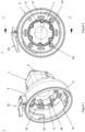
- Fig. 1:
- a perspective view of a preferred embodiment of an adapter according to the invention;
- Fig. 2:
- a front view of the adapter shown in
figure 1 ; - Fig. 3
- a longitudinal section of the adapter shown in
figure 1 ; and - Fig. 4
- an exploded view of the adapter shown in
figure 1 . - Fig. 5
- a perspective view of a preferred embodiment of an adapter according to the invention without the insert; and
- Fig. 6
- a cross section of the housing (circumferential wall) and the clutch shown in
figure 5 . - Terms such as "radial inner", "radial outer" and "axial" refer to a longitudinal axis x of a
housing 2 of theinventive adapter 1. - As shown in
figures 1, 2 and3 , a preferredaxial adapter 1 according to the invention adapted to be mounted to a kitchen appliance (not shown) and adapted to carry an attachment (not shown) of the kitchen appliance, hashousing 2 having a longitudinal axis x, acircumferential wall 4 with one radialinner end 6 and an opposite radialouter end 8. Both end faces are opened so that thehousing 2 is opened on both sides axially. - The radial
outer end 8 is adapted to be directed to the kitchen appliance and the radialinner end 6 is adapted to be directed to the attachment of the kitchen appliance. - Inside the
housing 2, parts of theadapter 1 are arranged which are required to transfer a rotation of a motor output shaft and a motor torque of an electric motor of the kitchen appliance to the attachment. - The parts are in particular a
clutch 12, abushing 14, a cup-like insert 16 (first part of the adapter 1) and a tubular part 18 (second part of the adapter 1), which will be explained in more detail with reference tofigures 3 and4 . - The clutch 12 is positioned rotatably on the longitudinal axis x of the
housing 2 and held in place by thebushing 14. The clutch 12 has a radialouter portion 20 and an opposite radialinner portion 22. The radialinner portion 22 has a greater axial extension than the radialouter portion 20. Bothportions fit structure 24, 26 (figure 3 ) in order to receive a corresponding form-fit structure of a motor shaft coupling element and of an attachment coupling element, respectively. Thereby, the radialouter portion 20 is adapted to act together with the corresponding form-fit structure of the motor shaft coupling element and the radialinner portion 22 is adapted to act together with the corresponding form-fit structure of the attachment coupling element. - On an outer surface of the radial
inner portion 22 close to the radialouter portion 20, preferably in or close to the axial centre of the clutch 12, anannular ring 28 is positioned. Theannular ring 28 acts as a form-fit element and is in engagement with anannular groove 30 on an inner surface of thebushing 14. Preferably, theannular ring 28 and the correspondinggrove 30 have a semi-circular shape. Due to the form-fit engagement caused by thering 28 and thegroove 30, the clutch 12 is fixed axially inside the brushing 14. In order to create a smooth, in particular a swing-free rotation of the clutch 12 around the longitudinal axis x, theannular ring 28 and thegroove 30 are designed in such a way that the clutch 12 is in surface contact withbushing 14, that means that no annular gap is provided between the clutch 12 and thebushing 14 surrounding the clutch 12 (figure 3 ). In order to keep any friction between the clutch 12 and thebushing 14 low, the clutch 12 and thebushing 14 are made of an adequate material, such as plastics materials. - The
bushing 14 has a radialinner portion 34 and radialouter portion 36, wherein the radialinner portion 34 is in contact with the cup-like insert 16 of theadapter 1 and the radialouter portion 36 is in contact with thetubular part 18 of theadapter 1. In particular, thebushing 14 is clamped axially between the cup-like insert 16 and thetubular part 18. Thebushing 14 is made of twosemi-circular elements bushing 14. In order to self-align the twosemi-circular elements fit elements radial portions bushing 14 are shorter than theradial portions - The cup-
like insert 16 has anopening 42 at its bottom side in order to receive the radialouter portion 20 of the clutch 12. Theopening 42 is surrounded by anannular protrusion 44 acting as counter-bearing (abutment) for thebushing 14. Theopening 42 has such an inner diameter that an annular gap 46 (figure 3 ) is provided to the radialouter portion 20 of the clutch 12, avoiding any friction between these parts when the clutch 12 is rotating. - The
insert 16 is releasably connected to thehousing 2 by means ofscrews 48 or a snap-connection (not shown). Here, the used screws 48 pass throughholes 50 in an annular bottom ring surrounding theopening 42 and are in engagement with respective thread holes of the housing 2 (not shown). By means of thescrews 48 thebushing 14 is clamped between theinsert 16 and thetubular part 18. - On its inner surface, the
insert 16 has a form-fit structure 52 in order to be attached to a correspondent form-fit structure on the kitchen appliance. Preferably, the form-fit structure 52 is designed as a bayonet connection. Theinsert 16 is preferably made of plastics materials. - The
tubular part 18 of theadapter 1 is formed integrally with thehousing 2. Oneaxial end 54 of thetubular part 18 is positioned inside thehousing 2 and acts as counter-bearing (abutment) for thebushing 14. Therefore, the axialinner end 54 has the same outer diameter as the radialinner portion 34 of thebushing 14. An inner diameter of thetubular part 18 is reduced compared with an inner diameter of the radialinner portion 34 of thebushing 14 at a whole, in order to provide an annular gap 56 (figure 3 ), thus avoiding any friction between the radialinner portion 22 of the clutch 12 and thetubular part 18 when the clutch 12 is rotating. The tubular part and the housing itself can be made of plastics materials or of any other adequate materials such as brushed aluminium or stainless steel. - Another axial
outer end 58 of thetubular part 18 is positioned outside thehousing 2. On its outer surface, a form-fit structure 60 is provided adapted to receive a corresponding form-fit structure of the attachment to be attached. Preferably, the form-fit structure 60 is designed as a bayonet connection. Thus, theadapter 1 has to on its both ends 6, 8 a form-fit structure, in particular bayonet systems. - In order to avoid that the
adapter 1 is removed unintentionally from the kitchen appliance, on the radialouter end 6 of the housing 2 a retaining means 62 adapted to be activated before theadapter 1 can be removed from the kitchen appliance is provided. Here, the retaining means 62 is a kind of known lever which is pivotable arranged on apin 63 orientated parallel to the longitudinal axis x of the housing and which has anose 64 adapted to be in engagement with a corresponding recess of the kitchen appliance. - In addition, in order to avoid that the attachment is removed unintentionally from the adapter, a release means 66 adapted to be activated before the attachment can be removed from the adapter is provided. Here, the release means 66 has a triangular body with an
axial pin 68 positioned in acorresponding recess 70 of thehousing 2 and biased by aspring 72 in axial direction. - Further on, in
figures 3 and4 fourrectangular bodies 74 are illustrated which are set in place in correspondingrectangular openings 76 of the cup-like insert 16. Therectangular bodies 74 can act as guiding means when attaching theadapter 1 to the kitchen appliance. -
Figures 5 and 6 depict theadapter 1 with thebushing 14 comprising at least onerecess 14c, preferably four, adapted to communicate with a correspondingprojection 77 on the inside of thehousing 2, more specifically of thecircumferential wall 4. Therecess 14c is shown also infigure 4 . - Assembling of the
adapter 1 is done by lying the twosemi-circular elements semi-circular elements annular ring 28 enters thegroove 30. After thebushing 14 has been mounted on the clutch 12, the clutch-bushing-arrangement is positioned inside the housing, wherein the radialinner portion 22 of the clutch 12 is inserted into thetubular part 18. Then, the cup-like insert 16 is positioned in thehousing 2 such that the radialouter portion 20 of the clutch 12 passes through theopening 42. Finally, thescrews 48 are tightened and thebushing 14 is clamped axially between the axialinner portion 54 of thetubular part 18 and theannular protrusion 44 of theinsert 16. - Disclosed is an
axial adapter 1 for a kitchen appliance driven by an electric motor, adapted to be mounted to the kitchen appliance and adapted to carry an attachment of the kitchen appliance, wherein theadapter 1 has ahousing 2 which is opened at its opposite end faces inside which a clutch 12 is positioned rotatably in order to transfer a rotation of a motor output shaft and a motor torque to the attachment, wherein the clutch 12 is in rotatable form-fit engagement with abushing 14 which is firmly clamped between afirst part 16 of theadapter 1 and asecond part 18 of theadapter 1 opposite to thefirst adapter part 16. -
- 1
- adapter
- 2
- housing
- 4
- circumferential wall
- 6
- radial inner end (housing)
- 8
- radial outer end (housing)
- 12
- clutch
- 14
- bushing
- 14a, 14b
- semi-circular elements
- 14c
- recess
- 16
- insert
- 18
- tubular part
- 20
- radial outer portion (clutch)
- 22
- radial inner portion (clutch)
- 24
- form-fit structure (clutch)
- 26
- form-fit structure (clutch)
- 28
- annular ring
- 30
- groove
- 34
- radial inner portion (bushing)
- 36
- radial outer portion (bushing)
- 38
- form-fit element (bushing)
- 40
- form-fit element (bushing)
- 42
- opening
- 44
- annular protrusion
- 46
- gap
- 48
- screw
- 50
- opening
- 52
- form-fit structure / bayonet (bushing)
- 54
- axial inner end (tubular part)
- 56
- gap
- 58
- axial outer end (tubular part)
- 60
- form-fit structure / bayonet (tubular part)
- 62
- retaining means
- 63
- pin
- 64
- nose
- 66
- release means
- 68
- axial pin
- 70
- recess
- 72
- spring
- 74
- rectangular body
- 76
- rectangular opening
- 77
- projection
- x
- longitudinal axis
Claims (11)
- Axial Adapter (1) for a kitchen appliance driven by an electric motor, adapted to be mounted to the kitchen appliance and adapted to carry an attachment of the kitchen appliance, wherein the adapter (1) has a housing (2) which is opened at its opposite end faces and inside which a clutch (12) is positioned rotatably in order to transfer a rotation of a motor output shaft and a motor torque to the attachment, characterised in that the clutch (12) is in rotatable form-fit engagement with a bushing (14) which is firmly clamped between a first part (16) of the adapter (1) and a second part (18) of the adapter (1) opposite to the first part (16).
- Adapter according to claim 1, wherein the first part (16) is a releasable cup-like insert which is fixed inside the housing (6) by screws (48) or snap connection and which has an opening (42) for the clutch (12).
- Adapter according to claims 1 or 2, wherein the second part (18) is an integral tubular portion of the housing (2).
- Adapter according to claims 1, 2 or 3, wherein the first part (16) has a form-fit structure (52) on its inner side adapted to act together with a counter form-fit portion of the kitchen appliance.
- Adapter according to claims 3 or 4, wherein the second part (18) has a form-fit structure (60) at its outer surface adapted to act together with a counter form-fit structure of the attachment.
- Adapter according to any of the preceding claims, wherein the form-fit engagement of the clutch (12) with the bushing (14) is formed by a ring (28) at an outer surface of the clutch (12) and by a counter groove (30) at an inner surface of the bushing (14).
- Adapter according to any of the preceding claims, wherein the bushing (14) is made of two semi-circular elements (14a, 14b).
- Adapter according to any of the preceding claims 2 to 7, wherein the bushing (14) has a radial inner portion (34) and radial outer portion (36), wherein the radial inner portion (34) is in contact with the second part (18) of the adapter (1) and the radial outer portion (36) is in contact with the first part (16) of the adapter (1).
- Adapter according to any of the preceding claims, wherein the clutch (12) has a radial outer portion (20) and a radial inner portion (22), and wherein the clutch (12) has a greater axial extension than the bushing (14), and wherein the ring (28) is positioned on the radial inner portion (22) close to the radial outer portion (20).
- Adapter according to any of the preceding claims, wherein the adapter (1) has a retaining means (62) adapted to be deactivated before the adapter (1) can be removed from the kitchen appliance and a release means (66) adapted to be deactivated before the attachment can be removed from the adapter (1).
- Adapter according to any of the preceding claims, wherein the bushing (14) comprises at least one recess (14c) adapted to communicate with a projection (77) on the inside of the housing (2).
Priority Applications (1)
| Application Number | Priority Date | Filing Date | Title |
|---|---|---|---|
| EP21189900.0A EP4129132B1 (en) | 2021-08-05 | 2021-08-05 | Axial adapter for kitchen appliance |
Applications Claiming Priority (1)
| Application Number | Priority Date | Filing Date | Title |
|---|---|---|---|
| EP21189900.0A EP4129132B1 (en) | 2021-08-05 | 2021-08-05 | Axial adapter for kitchen appliance |
Publications (3)
| Publication Number | Publication Date |
|---|---|
| EP4129132A1 true EP4129132A1 (en) | 2023-02-08 |
| EP4129132B1 EP4129132B1 (en) | 2024-03-27 |
| EP4129132C0 EP4129132C0 (en) | 2024-03-27 |
Family
ID=77226714
Family Applications (1)
| Application Number | Title | Priority Date | Filing Date |
|---|---|---|---|
| EP21189900.0A Active EP4129132B1 (en) | 2021-08-05 | 2021-08-05 | Axial adapter for kitchen appliance |
Country Status (1)
| Country | Link |
|---|---|
| EP (1) | EP4129132B1 (en) |
Citations (5)
| Publication number | Priority date | Publication date | Assignee | Title |
|---|---|---|---|---|
| DE865524C (en) * | 1942-10-13 | 1953-02-02 | Siemens Ag | Kitchen engine |
| DE1055773B (en) * | 1953-04-24 | 1959-04-23 | Max Braun Fa | Gear head for electrically operated kitchen machines |
| DE2461286A1 (en) * | 1974-12-23 | 1976-07-01 | Bosch Siemens Hausgeraete | Household mixer with removable bowl with central bearing sleeve - has resilient sealing ring for perfect simple seal of sleeve and coupling shaft |
| EP0529287A2 (en) * | 1991-08-28 | 1993-03-03 | Braun Aktiengesellschaft | Comminuting device for an electrical kitchen appliance |
| EP3292804A1 (en) * | 2016-08-26 | 2018-03-14 | BSH Hausgeräte GmbH | Kitchen machine transmission adaptor with locking lever |
-
2021
- 2021-08-05 EP EP21189900.0A patent/EP4129132B1/en active Active
Patent Citations (5)
| Publication number | Priority date | Publication date | Assignee | Title |
|---|---|---|---|---|
| DE865524C (en) * | 1942-10-13 | 1953-02-02 | Siemens Ag | Kitchen engine |
| DE1055773B (en) * | 1953-04-24 | 1959-04-23 | Max Braun Fa | Gear head for electrically operated kitchen machines |
| DE2461286A1 (en) * | 1974-12-23 | 1976-07-01 | Bosch Siemens Hausgeraete | Household mixer with removable bowl with central bearing sleeve - has resilient sealing ring for perfect simple seal of sleeve and coupling shaft |
| EP0529287A2 (en) * | 1991-08-28 | 1993-03-03 | Braun Aktiengesellschaft | Comminuting device for an electrical kitchen appliance |
| EP3292804A1 (en) * | 2016-08-26 | 2018-03-14 | BSH Hausgeräte GmbH | Kitchen machine transmission adaptor with locking lever |
Also Published As
| Publication number | Publication date |
|---|---|
| EP4129132B1 (en) | 2024-03-27 |
| EP4129132C0 (en) | 2024-03-27 |
Similar Documents
| Publication | Publication Date | Title |
|---|---|---|
| US4630847A (en) | Multiple tube connector | |
| US5113571A (en) | Method of manufacturing a connector for medical devices | |
| US5667332A (en) | Locking device for a drive shaft | |
| US6164910A (en) | Housing assembly for a fluid-working device such as a rotary pump | |
| JP4043365B2 (en) | Instantaneous connection coupling device | |
| US5934156A (en) | Close-connected shaft adapter assembly, jack shaft assembly, and power transmission assembly using same | |
| JP6185778B2 (en) | Rotor mounting structure | |
| KR970006005B1 (en) | Coupling element for frictionally connection an external component to a shaft | |
| JPH03212244A (en) | Snap assembly housing | |
| JP2851437B2 (en) | Coupling mechanism to quickly align the rotor with the journal | |
| EP0577064A1 (en) | Rotary pump | |
| CN103574150A (en) | Ball valve | |
| CN109262662B (en) | Coupling unit | |
| EP4129132B1 (en) | Axial adapter for kitchen appliance | |
| KR101922557B1 (en) | Integrated drive apparatus | |
| JP7416752B2 (en) | power tool attachment parts | |
| US7316424B2 (en) | Fast-fit coupling for connecting appliances forming part of a medical or surgical handpiece system to a supply hose | |
| EP1224401A1 (en) | Multiple-connection engagement shaft coupling | |
| US4645282A (en) | Releasing electrical connector assembly | |
| US20130111699A1 (en) | Vacuum cleaner hose assembly connector | |
| US4468078A (en) | Forwardly removable coupling ring for an electrical connector | |
| EP1625641B1 (en) | Coupling device for the contact block and the handle of an electrical connector | |
| US20060040750A1 (en) | Shaft coupling assembly | |
| JP4032406B2 (en) | Pipe fitting | |
| GB2620436A (en) | Aseptic connector |
Legal Events
| Date | Code | Title | Description |
|---|---|---|---|
| PUAI | Public reference made under article 153(3) epc to a published international application that has entered the european phase |
Free format text: ORIGINAL CODE: 0009012 |
|
| STAA | Information on the status of an ep patent application or granted ep patent |
Free format text: STATUS: THE APPLICATION HAS BEEN PUBLISHED |
|
| AK | Designated contracting states |
Kind code of ref document: A1 Designated state(s): AL AT BE BG CH CY CZ DE DK EE ES FI FR GB GR HR HU IE IS IT LI LT LU LV MC MK MT NL NO PL PT RO RS SE SI SK SM TR |
|
| STAA | Information on the status of an ep patent application or granted ep patent |
Free format text: STATUS: REQUEST FOR EXAMINATION WAS MADE |
|
| 17P | Request for examination filed |
Effective date: 20230808 |
|
| RBV | Designated contracting states (corrected) |
Designated state(s): AL AT BE BG CH CY CZ DE DK EE ES FI FR GB GR HR HU IE IS IT LI LT LU LV MC MK MT NL NO PL PT RO RS SE SI SK SM TR |
|
| GRAP | Despatch of communication of intention to grant a patent |
Free format text: ORIGINAL CODE: EPIDOSNIGR1 |
|
| STAA | Information on the status of an ep patent application or granted ep patent |
Free format text: STATUS: GRANT OF PATENT IS INTENDED |
|
| RIC1 | Information provided on ipc code assigned before grant |
Ipc: A47J 43/08 20060101ALI20231027BHEP Ipc: A47J 43/07 20060101AFI20231027BHEP |
|
| INTG | Intention to grant announced |
Effective date: 20231117 |
|
| GRAS | Grant fee paid |
Free format text: ORIGINAL CODE: EPIDOSNIGR3 |
|
| GRAA | (expected) grant |
Free format text: ORIGINAL CODE: 0009210 |
|
| STAA | Information on the status of an ep patent application or granted ep patent |
Free format text: STATUS: THE PATENT HAS BEEN GRANTED |
|
| AK | Designated contracting states |
Kind code of ref document: B1 Designated state(s): AL AT BE BG CH CY CZ DE DK EE ES FI FR GB GR HR HU IE IS IT LI LT LU LV MC MK MT NL NO PL PT RO RS SE SI SK SM TR |
|
| REG | Reference to a national code |
Ref country code: GB Ref legal event code: FG4D |
|
| REG | Reference to a national code |
Ref country code: CH Ref legal event code: EP |
|
| REG | Reference to a national code |
Ref country code: DE Ref legal event code: R096 Ref document number: 602021010864 Country of ref document: DE |
|
| REG | Reference to a national code |
Ref country code: IE Ref legal event code: FG4D |
|
| U01 | Request for unitary effect filed |
Effective date: 20240419 |
|
| U07 | Unitary effect registered |
Designated state(s): AT BE BG DE DK EE FI FR IT LT LU LV MT NL PT SE SI Effective date: 20240426 |
|
| PG25 | Lapsed in a contracting state [announced via postgrant information from national office to epo] |
Ref country code: GR Free format text: LAPSE BECAUSE OF FAILURE TO SUBMIT A TRANSLATION OF THE DESCRIPTION OR TO PAY THE FEE WITHIN THE PRESCRIBED TIME-LIMIT Effective date: 20240628 |
|
| PG25 | Lapsed in a contracting state [announced via postgrant information from national office to epo] |
Ref country code: RS Free format text: LAPSE BECAUSE OF FAILURE TO SUBMIT A TRANSLATION OF THE DESCRIPTION OR TO PAY THE FEE WITHIN THE PRESCRIBED TIME-LIMIT Effective date: 20240627 Ref country code: HR Free format text: LAPSE BECAUSE OF FAILURE TO SUBMIT A TRANSLATION OF THE DESCRIPTION OR TO PAY THE FEE WITHIN THE PRESCRIBED TIME-LIMIT Effective date: 20240327 |
|
| PG25 | Lapsed in a contracting state [announced via postgrant information from national office to epo] |
Ref country code: RS Free format text: LAPSE BECAUSE OF FAILURE TO SUBMIT A TRANSLATION OF THE DESCRIPTION OR TO PAY THE FEE WITHIN THE PRESCRIBED TIME-LIMIT Effective date: 20240627 Ref country code: NO Free format text: LAPSE BECAUSE OF FAILURE TO SUBMIT A TRANSLATION OF THE DESCRIPTION OR TO PAY THE FEE WITHIN THE PRESCRIBED TIME-LIMIT Effective date: 20240627 Ref country code: HR Free format text: LAPSE BECAUSE OF FAILURE TO SUBMIT A TRANSLATION OF THE DESCRIPTION OR TO PAY THE FEE WITHIN THE PRESCRIBED TIME-LIMIT Effective date: 20240327 Ref country code: GR Free format text: LAPSE BECAUSE OF FAILURE TO SUBMIT A TRANSLATION OF THE DESCRIPTION OR TO PAY THE FEE WITHIN THE PRESCRIBED TIME-LIMIT Effective date: 20240628 |
|
| PG25 | Lapsed in a contracting state [announced via postgrant information from national office to epo] |
Ref country code: IS Free format text: LAPSE BECAUSE OF FAILURE TO SUBMIT A TRANSLATION OF THE DESCRIPTION OR TO PAY THE FEE WITHIN THE PRESCRIBED TIME-LIMIT Effective date: 20240727 |
|
| U20 | Renewal fee for the european patent with unitary effect paid |
Year of fee payment: 4 Effective date: 20240902 |
|
| PG25 | Lapsed in a contracting state [announced via postgrant information from national office to epo] |
Ref country code: SM Free format text: LAPSE BECAUSE OF FAILURE TO SUBMIT A TRANSLATION OF THE DESCRIPTION OR TO PAY THE FEE WITHIN THE PRESCRIBED TIME-LIMIT Effective date: 20240327 |
|
| PG25 | Lapsed in a contracting state [announced via postgrant information from national office to epo] |
Ref country code: ES Free format text: LAPSE BECAUSE OF FAILURE TO SUBMIT A TRANSLATION OF THE DESCRIPTION OR TO PAY THE FEE WITHIN THE PRESCRIBED TIME-LIMIT Effective date: 20240327 |
|
| PG25 | Lapsed in a contracting state [announced via postgrant information from national office to epo] |
Ref country code: CZ Free format text: LAPSE BECAUSE OF FAILURE TO SUBMIT A TRANSLATION OF THE DESCRIPTION OR TO PAY THE FEE WITHIN THE PRESCRIBED TIME-LIMIT Effective date: 20240327 |
|
| PG25 | Lapsed in a contracting state [announced via postgrant information from national office to epo] |
Ref country code: PL Free format text: LAPSE BECAUSE OF FAILURE TO SUBMIT A TRANSLATION OF THE DESCRIPTION OR TO PAY THE FEE WITHIN THE PRESCRIBED TIME-LIMIT Effective date: 20240327 |
|
| PG25 | Lapsed in a contracting state [announced via postgrant information from national office to epo] |
Ref country code: SK Free format text: LAPSE BECAUSE OF FAILURE TO SUBMIT A TRANSLATION OF THE DESCRIPTION OR TO PAY THE FEE WITHIN THE PRESCRIBED TIME-LIMIT Effective date: 20240327 |
|
| PG25 | Lapsed in a contracting state [announced via postgrant information from national office to epo] |
Ref country code: SM Free format text: LAPSE BECAUSE OF FAILURE TO SUBMIT A TRANSLATION OF THE DESCRIPTION OR TO PAY THE FEE WITHIN THE PRESCRIBED TIME-LIMIT Effective date: 20240327 Ref country code: SK Free format text: LAPSE BECAUSE OF FAILURE TO SUBMIT A TRANSLATION OF THE DESCRIPTION OR TO PAY THE FEE WITHIN THE PRESCRIBED TIME-LIMIT Effective date: 20240327 Ref country code: RO Free format text: LAPSE BECAUSE OF FAILURE TO SUBMIT A TRANSLATION OF THE DESCRIPTION OR TO PAY THE FEE WITHIN THE PRESCRIBED TIME-LIMIT Effective date: 20240327 Ref country code: PL Free format text: LAPSE BECAUSE OF FAILURE TO SUBMIT A TRANSLATION OF THE DESCRIPTION OR TO PAY THE FEE WITHIN THE PRESCRIBED TIME-LIMIT Effective date: 20240327 Ref country code: IS Free format text: LAPSE BECAUSE OF FAILURE TO SUBMIT A TRANSLATION OF THE DESCRIPTION OR TO PAY THE FEE WITHIN THE PRESCRIBED TIME-LIMIT Effective date: 20240727 Ref country code: ES Free format text: LAPSE BECAUSE OF FAILURE TO SUBMIT A TRANSLATION OF THE DESCRIPTION OR TO PAY THE FEE WITHIN THE PRESCRIBED TIME-LIMIT Effective date: 20240327 Ref country code: CZ Free format text: LAPSE BECAUSE OF FAILURE TO SUBMIT A TRANSLATION OF THE DESCRIPTION OR TO PAY THE FEE WITHIN THE PRESCRIBED TIME-LIMIT Effective date: 20240327 |
|
| REG | Reference to a national code |
Ref country code: DE Ref legal event code: R097 Ref document number: 602021010864 Country of ref document: DE |
|
| PLBE | No opposition filed within time limit |
Free format text: ORIGINAL CODE: 0009261 |
|
| STAA | Information on the status of an ep patent application or granted ep patent |
Free format text: STATUS: NO OPPOSITION FILED WITHIN TIME LIMIT |
|
| 26N | No opposition filed |
Effective date: 20250103 |
|
| REG | Reference to a national code |
Ref country code: CH Ref legal event code: PL |
|
| PG25 | Lapsed in a contracting state [announced via postgrant information from national office to epo] |
Ref country code: MC Free format text: LAPSE BECAUSE OF FAILURE TO SUBMIT A TRANSLATION OF THE DESCRIPTION OR TO PAY THE FEE WITHIN THE PRESCRIBED TIME-LIMIT Effective date: 20240327 Ref country code: CH Free format text: LAPSE BECAUSE OF NON-PAYMENT OF DUE FEES Effective date: 20240831 |
|
| PG25 | Lapsed in a contracting state [announced via postgrant information from national office to epo] |
Ref country code: IE Free format text: LAPSE BECAUSE OF NON-PAYMENT OF DUE FEES Effective date: 20240805 |
|
| U20 | Renewal fee for the european patent with unitary effect paid |
Year of fee payment: 5 Effective date: 20250901 |
|
| PG25 | Lapsed in a contracting state [announced via postgrant information from national office to epo] |
Ref country code: CY Free format text: LAPSE BECAUSE OF FAILURE TO SUBMIT A TRANSLATION OF THE DESCRIPTION OR TO PAY THE FEE WITHIN THE PRESCRIBED TIME-LIMIT; INVALID AB INITIO Effective date: 20210805 |
|
| PG25 | Lapsed in a contracting state [announced via postgrant information from national office to epo] |
Ref country code: HU Free format text: LAPSE BECAUSE OF FAILURE TO SUBMIT A TRANSLATION OF THE DESCRIPTION OR TO PAY THE FEE WITHIN THE PRESCRIBED TIME-LIMIT; INVALID AB INITIO Effective date: 20210805 |
|
| GBPC | Gb: european patent ceased through non-payment of renewal fee |
Effective date: 20250805 |