EP4129112A1 - Slide fastener and design method thereof - Google Patents
Slide fastener and design method thereof Download PDFInfo
- Publication number
- EP4129112A1 EP4129112A1 EP20929605.2A EP20929605A EP4129112A1 EP 4129112 A1 EP4129112 A1 EP 4129112A1 EP 20929605 A EP20929605 A EP 20929605A EP 4129112 A1 EP4129112 A1 EP 4129112A1
- Authority
- EP
- European Patent Office
- Prior art keywords
- fastener
- protrusion
- slider
- elements
- fastener elements
- Prior art date
- Legal status (The legal status is an assumption and is not a legal conclusion. Google has not performed a legal analysis and makes no representation as to the accuracy of the status listed.)
- Granted
Links
Images




Classifications
-
- A—HUMAN NECESSITIES
- A44—HABERDASHERY; JEWELLERY
- A44B—BUTTONS, PINS, BUCKLES, SLIDE FASTENERS, OR THE LIKE
- A44B19/00—Slide fasteners
- A44B19/02—Slide fasteners with a series of separate interlocking members secured to each stringer tape
- A44B19/04—Stringers arranged edge-to-edge when fastened, e.g. abutting stringers
- A44B19/06—Stringers arranged edge-to-edge when fastened, e.g. abutting stringers with substantially rectangular members having interlocking projections and pieces
Definitions
- the present disclosure concerns a slide fastener and a design method thereof.
- Patent literature 1 discloses fastener elements having engaging protrusions on its both sides as illustrated in Fig. 4 thereof.
- a recess 10 is formed as illustrated in Fig. 2 thereof to avoid a raised portion 58 shown in Fig. 10 thereof.
- Patent literature 2 discloses fastener elements having an engaging protrusion on its one side and an engaged recess on the other side. Sloped surface 8 is formed as shown in Fig. 2 (b) of the literature, facilitating smooth engagement of the fastener elements.
- a rear protrusion of the posterior fastener element E2' of those left and right fastener elements E1' and E2' come into contact with a front protrusion of a fastener element E3', and thus greater force would be required to allow a rear protrusion of the fastener element E 1' to move across a front protrusion of the fastener element E2', i.e. increased resistance for sliding the slider.
- fastener elements E 1' and E2' (E2' and E3') paired for initial contact would be kept in contact between a first position away from a rear end of the coupling pillar 93 of the slider 9 by a first distance D1' to a second position away from the rear end of the coupling pillar 93 by a second distance D2'.
- a technical problem the present invention concerns is to reduce the resistance for sliding a slider while maintaining sufficient height of the front and rear protrusions of the fastener elements.
- Slide fastener includes: left and right fastener stringers with fastener elements attached to opposed side-edges of fastener tapes, each fastener element including an attachment base secured to the side-edge of the fastener tape and a head having an engagement protrusion positioned away from said side-edge of the fastener tape, and the engagement protrusion including a front protrusion protruding forward and a rear protrusion protruding rearward; and a slider that moves forward to engage left and right fastener elements included in the left and right fastener stringers, the left and right fastener elements coming into initial contact on the front protrusion and the rear protrusion alternately inside of the slider as the slider moves forward.
- the engagement protrusion includes: nearer sloped surfaces that diverge from each other as being away from the attachment base; farther sloped surfaces that approach each other as being away from the attachment base; and top portions each of which being formed between the nearer sloped surface and the farther sloped surface.
- the farther sloped surface is sectioned into plural sloped regions having different angles of inclination, and the sloped region situated closer to the top portion may be inclined more gently than the sloped region situated farther from the top portion.
- the left and right fastener elements come into initial contact on the respective sloped regions situated closer to the top portion.
- the top portion may include a flat surface that extends evenly along a direction the head protrudes from the side-edge of the fastener tape. Initial contact position of the left and right fastener elements may be on a center line of the slider.
- the head may include a plate portion having a thickness defined by a front surface on which the front protrusion is arranged and a rear surface on which the rear protrusion is arranged, said thickness being less than a thickness of the attachment base. Front recess may be formed between the front protrusion and the attachment base, and a rear recess may be formed between the rear protrusion and the attachment base.
- a method of designing a slide fastener is one for designing a slide fastener that includes: left and right fastener stringers with fastener elements attached to side-edges of fastener tapes, each fastener element including an attachment base secured to the side-edge of the fastener tape and a head having an engagement protrusion positioned away from said side-edge of the fastener tape, and the engagement protrusion including a front protrusion protruding forward and a rear protrusion protruding rearward; and a slider that moves forward to engage left and right fastener elements included in the left and right fastener stringers, the left and right fastener elements coming into initial contact on the front protrusion and the rear protrusion alternately as the slider moves forward.
- the present designing method allows, when a given pair of left and right fastener elements included in the left and right fastener elements come into initial contact on the rear protrusion of an anterior fastener element of the given pair of left and right fastener elements and the front protrusion of a posterior fastener element of the given pair of left and right fastener elements inside of the slider, the rear protrusion of the posterior fastener element to be not in contact with the front protrusion of a fastener element immediately posterior to said posterior fastener element.
- An aspect of the present disclosure facilitates reduction of resistance for sliding a slider while maintaining sufficient height of the front and rear protrusions of fastener elements.
- front-rear direction would be understood based on movement of slider 9.
- Direction of movement of the slider 9 for closing fastener stringers 3 and 4 is equal to a forward direction.
- Direction of movement of the slider 9 for opening fastener stringers 3 and 4 is equal to a rearward direction.
- Left-right direction would be understood based on fastener stringers 3 and 4 to be closed and opened by the slider 9.
- Up-down direction is orthogonal to the front-rear direction and the left-right direction and, for example, is orthogonal to tape faces of a fastener tape which define a thickness of the fastener tape.
- a slide fastener 1 has left and right fastener stringers 3 and 4, and a slider 9 that moves forward to close the left and right fastener stringers 3 and 4 and moves rearward to open the left and right fastener stringers 3 and 4.
- the fastener stringer 3, 4 has a fastener tape 11, 12 and fastener elements 21, 22.
- the fastener elements 21 and 22 are attached to opposed side-edges 13 and 14 of the fastener tapes 11 and 12.
- the fastener tapes 11 and 12 are respectively provided with front stops 81 and 82 each of which is positioned adjacent to a front end of an array of the fastener element 21, 22.
- the left and right fastener stringers 3 and 4 are coupled by a common rear stop 83 at the rear ends of the arrays of the fastener elements 21 and 22.
- a stop separable in the left-right direction can be employed.
- the front stop 81, 82 and the rear stop 83 can be omitted.
- the slide fastener should not be limited to one disclosed in Fig. 1 .
- the present invention can be adapted to a conceal slide fastener in which fastener elements are concealed by fastener tape not to be seen.
- the fastener tape 11, 12 is a soft fabric such as woven fabric or knitted fabric or mixture thereof, and is elongated in the front-rear direction and is narrow in the left-right direction. Thickness of the fastener tape 11, 12 is defined by upper and lower tape faces. The tape face has a pattern in accordance with woven or knitted structure of the fastener tape 11, 12. In some cases, the opposed side-edges 13 and 14 of the fastener tapes 11 and 12 are provided with core threads, facilitating firmer attachment of the fastener elements 21 and 22. The core thread has a diameter larger than the thickness of the fastener tape 11, 12.
- the fastener element 21, 22 is a metal or plastic element. In cases where the fastener elements 21, 22 are made of metal, the fastener elements 21,22 are swaged and attached to the side-edge 13, 14 (e.g. the core thread there) of the fastener tape 11, 12. Each one of the fastener elements 21, 22 is produced through cutting and pressing of metal material. Each one of the fastener elements 21, 22 is polished to have a glossy surface thereof. In cases where the fastener elements 21, 22 are resin, the fastener elements 21, 22 are adhered to the side-edge 13, 14 (e.g. the core thread there) of the fastener tape 11, 12 through injection molding. Embodiments are envisioned where other materials (e.g. ceramic) are used for the fastener elements 21, 22.
- other materials e.g. ceramic
- the fastener element 21, 22 has an attachment base 31,32 secured to the side-edge 13,14 of the fastener tape 11,12 and a head 33, 34 having an engagement protrusion B1,B2 positioned away from the side-edge 13, 14 of the fastener tape 11, 12.
- the attachment base 31,32 has legs 51 and 52 which are arranged to pinch the side-edge 13, 14 of the fastener tape 11,12, and a coupling portion 53 to which the base ends of the legs 51 and 52 are coupled.
- the legs 51 and 52 extend away from the coupling portion 53 in the left-right direction outwardly (i.e.
- legs 51 and 52 which is for accommodating the side-edge 13, 14 (e.g. the core thread there) of the fastener tape 11, 12.
- the legs 51 and 52 are provided with projections 51a and 52a at their terminal ends, thus preventing the side-edge 13, 14 (e.g. the core thread) from moving out of the accommodating space between the legs 51 and 52.
- the head 33, 34 extends from the attachment base 31, 32 in the left-right direction inwardly (i.e. a direction directed toward the center line CL of the slide fastener in the left-right direction).
- the engagement protrusion B1, B2 provided in the head 33, 34 includes a front protrusion 41, 43 protruding forward and a rear protrusion 42, 44 protruding rearward.
- the front protrusion 41 and the rear protrusion 42 are protruded to the opposite side on the same axis. The same holds true to the front protrusion 43 and the rear protrusion 44.
- the head 33, 34 includes a plate portion 56 having a thickness defined by a front surface 56a on which the front protrusion 41, 43 is arranged and a rear surface 56b on which the rear protrusion 42, 44 is arranged.
- the thickness of the plate portion 56 (in the front-rear direction) is less than the thickness of the attachment base 31,32 (in the front-rear direction).
- a front recess 57 is formed between the front protrusion 41 (similarly the front protrusion 43) and the attachment base 31, and a rear recess 58 is formed between the rear protrusion 42 (similarly the rear protrusion 44) and the attachment base 31.
- the front protrusion 41, 43 and the rear protrusion 42, 44 are arranged slightly offset closer to the attachment base 31, 32 relative to an end surface 56c of the plate portion 56.
- the engagement protrusion B1 (similarly the engagement protrusion B2) has nearer sloped surfaces 61 on the front and rear sides which diverge from each other as being away from the attachment base 31, 32; farther sloped surfaces 62 (62a, 62b) on the front and rear sides which approach each other as being away from the attachment base 31, 32; and top portions 63 on the front and rear sides formed between the nearer sloped surface 61 and the farther sloped surface 62.
- the front protrusion 41, 43 is defined by the top portion 63 on the front side, the nearer sloped surface 61 and the farther sloped surface 62 on the front side which approach each other as being away from the plate portion 56 of the head 33,34.
- the rear protrusion 42, 44 is defined by the top portion 63 on the rear side, the nearer sloped surface 61 and the farther sloped surface 62 on the rear side which approach each other as being away from the plate portion 56 of the head 33,34.
- the farther sloped surface 62 is sectioned into plural sloped regions 62a, 62b having different angles of inclination, and the sloped region 62a situated closer to the top portion 63 is inclined more gently than the sloped region 62b situated farther from the top portion 63.
- the sloped region 62a situated closer to the top portion 63 is gently angled owing to the division of the farther sloped surface 62 into the differently angled sloped regions 62a and 62b. This would contribute to reduction of resistance for sliding the slider 9 as would be understood from the following descriptions.
- the top portion 63 includes a flat surface that extends evenly along a direction the head 33, 34 protrudes from the side-edge 13, 14 of the fastener tape 11, 12, contributing in reduction of resistance for sliding the slider 9.
- the fastener element 21,22 further has walls 54a and 55a which restrict the displacement, in the up-down direction, of a rear protrusion 42 of another fastener element 21,22 which has been received in the front recess 57 (See Figs. 3 and 4 ).
- the fastener element 21,22 has walls 54b and 55b which restrict the displacement, in the up-down direction, of a front protrusion 41 of another fastener element 21,22 which has been received in the rear recess 58 (See Fig. 4 ).
- the wall 54a, 54b, 55a, 55b extends and tapers from the attachment base 31, 32 in the left-right direction inwardly. The widths of the front recess 57 and the rear recess 58 are gradually increased as being away from the attachment base 31, 32.
- the slider 9 is configured to engage and disengage the left and right fastener elements 21 and 22.
- Material of the slider 9 may be metal or plastic or ceramic for example, but may be a composite of these materials.
- the slider 9 has a top wing 91, a bottom wing 92, and a coupling pillar 93.
- Left and right front-mouths 94m and 94n are arranged at the both left and right sides of the coupling pillar 93 and a rear-mouth 95 is arranged at the opposite side of the front mouths 94m and 94n.
- the center line of the slider 9 matches the center line CL of the slide fastener 1.
- the coupling pillar 93 has a cross-sectional shape in which the width in the left-right direction is gradually reduced rearward. Therefore, the coupling pillar 93 has left and right guide surfaces 93m and 93n that approach each other rearward. The end surface 56c of the plate portion 56 of the head 33, 34 of the fastener element 21, 22 may come into contact with the guide surface 93m, 93n.
- Flanges (not-illustrated) protruding downward may be arranged at the left and right side-edges of the top wing 91 to restrict the displacement in the left-right direction of the left and right fastener elements 21,22.
- flanges 96m and 96n protruding upward may be arranged at the left and right side-edges of the bottom wing 92 (See Fig. 6 ).
- the flange (not-illustrated) at the left side-edge of the top wing 91 and the flange 96m at the left side-edge of the bottom wing 92 are opposed, defining an insertion space for the left fastener tape 11.
- the flange (not-illustrated) at the right side-edge of the top wing 91 and the flange 96n at the right side-edge of the bottom wing 92 are opposed, defining an insertion space for the right fastener tape 12.
- the left and right fastener elements 21 and 22 come into initial contact on the front protrusion 41, 43 and the rear protrusion 42, 44 thereof alternately inside of the slider 9 as the slider 9 moves forward.
- the initial contact is caused when the slider 9 moves forward.
- the left and right fastener elements 21 and 22 enter into the inside of the slider 9 via the front mouths 94m and 94n of the slider 9.
- the left and right fastener elements 21 and 22 having entered into the inside of the slider 9 via the front mouths 94m and 94n are separated as there is the coupling pillar 93 between them.
- these left and right fastener elements 21 and 22 move rearward further away from the left and right front-mouths 94m and 94n, thus the interspace J between them in the left-right direction gradually decreases.
- these left and right fastener elements 21 and 22 come into initial contact.
- the initial contact can be caused between the rear protrusion 42 of the fastener element 21 and the front protrusion 43 of the fastener element 22 (See Fig. 6 ).
- the initial contact can be caused between the front protrusion 41 of the fastener element 21 and the rear protrusion 44 of the fastener element 22 (See Fig. 7 ).
- the left and right fastener elements 21 and 22 come into initial contact on the front protrusion 41, 43 and the rear protrusion 42, 44 alternately inside of the slider 9 as the slider 9 moves forward, as described above.
- FIG. 7 As depicted in Fig. 7 , when a given pair of left and right fastener elements E0 and E1 come into initial contact on the rear protrusion 44 of the anterior fastener element E0 and the front protrusion 41 of the posterior fastener element E1, the rear protrusion 42 of the posterior fastener element E1 is not in contact with the front protrusion 43 of the fastener element E2 with which the posterior fastener element E1 came into initial contact at its rear protrusion 42 in advance (i.e. the initial contact in Fig. 6 ).
- the rear protrusion 42 of the fastener element E1 and the front protrusion 43 of the fastener element E2 come into contact on their respective sloped regions 62a of the farther sloped surfaces 62.
- the rear protrusion 44 of the fastener element E0 and the front protrusion 41 of the fastener element E1 come into contact on their respective sloped regions 62a of the farther sloped surfaces 62.
- the rear protrusion slides on the sloped region 62a and moves across the top portion 63 of the front protrusion, and then enters into the front recess 57.
- the front protrusion slides on the sloped region 62a and moves across the top portion 63 of the rear protrusion, and then enters into the rear recess 58.
- the front protrusion and the rear recess are fitted and the rear protrusion and the front recess are fitted, thereby the left and right fastener elements E1 and E2 are engaged and the strength of slide fastener 1 would be ensured against a lateral pulling force.
- a strength of slide fastener 1 against thrust in the up-down direction would be ensured.
- the fastener elements E1 and E2 come into initial contact on the center line CL of slider 9.
- This initial contact point P1 is away from the rear end of the coupling pillar 93 by a first distance D1.
- An intersection point P2 between the center line Cl of the slider 9 and the rear protrusion 44 (the sloped region 62a of the farther sloped surface 62) of the fastener element E2 is away from the rear end of the coupling pillar 93 by a second distance D2 (See Fig. 6 ).
- intersection point P3 between the center line CL of the slider 9 and the front protrusion 41 (the sloped region 62a of the farther sloped surface 62 described above) of the fastener element E3 is away from the rear end of the coupling pillar 93 by a third distance D3 (See Fig. 6 ).
- the intersection points P2 and P3 are intersection points at the time of initial contact between the fastener elements E 1 and E2. Equation of D1 ⁇ D2 ⁇ D3 is satisfied.
- the equation of D2 ⁇ D3 indicates the existence of space between the rear protrusion 44 of the fastener element E2 and the front protrusion 41 of the fastener element E3.
- the fastener elements E1 and E2 (see Fig. 6 ) which have come into initial contact at the initial contact point away from the rear end of the coupling pillar 93 by the first distance D1 would cease to be in contact before the next pair of fastener elements E0 and E1 for initial contact come into initial contact (see Fig. 7 ).
- the pair of fastener elements E0 and E1 for the next initial contact come into initial contact
- the pair of fastener elements E1 and E2 for the previous initial contact are not in contact (in more particular, there is a space between the rear protrusion 42 of the fastener element E1 and the front protrusion 43 of the fastener element E2), and the fastener element E1 can move more freely, thus reducing the resistance for sliding the slider 9.
- a design can be employed which, when the pair of left and right fastener elements E0 and E1 come into initial contact on the rear protrusion 44 of the anterior fastener element E0 thereof and the front protrusion 41 of the posterior fastener element E1 thereof inside of the slider 9, allows the rear protrusion 42 of the posterior fastener element E1 not to be in contact with the front protrusion 43 of the fastener element E2 with which the posterior fastener element E1 came into initial contact at its rear protrusion 42 in advance.
- This method of designing may include determining the initial contact position for the fastener elements 21 and 22 appropriately and may shorten the distance D1 than before, for example.
- This method of designing may include appropriately determining the position of the engagement protrusion B1, B2 relative to the attachment base 31, 32 for a purpose of adjustment of the first distance D1.
- This method of designing may include appropriately shaping the front protrusion 41 and the rear protrusion 42 for a purpose of adjustment of the first distance D1 or smooth engagement between the fastener elements, and may section the farther sloped surface 62 as described above, for example.
- This method of designing can be performed by computer software.
Landscapes
- Slide Fasteners (AREA)
Abstract
Description
- The present disclosure concerns a slide fastener and a design method thereof.
-
Patent literature 1 discloses fastener elements having engaging protrusions on its both sides as illustrated inFig. 4 thereof. A recess 10 is formed as illustrated inFig. 2 thereof to avoid a raisedportion 58 shown in Fig. 10 thereof. - Patent literature 2 discloses fastener elements having an engaging protrusion on its one side and an engaged recess on the other side. Sloped surface 8 is formed as shown in Fig. 2 (b) of the literature, facilitating smooth engagement of the fastener elements.
-
- [PTL 1]
Japanese Patent No. 5460862 - [PTL 2]
Japanese Patent No. 5042358 - Recently, there is an increasing demand for lesser force for moving a slider so as to close a slide fastener even though there has been hardly ever for such demand before. The present inventors has conducted keen analysis on this matter and revealed that a type of slide fastener disclosed in the
patent literature 1 has a following problem. In particular, as illustrated inFig. 8 , left and right fastener elements E1' and E2' come into initial contact inside of the slider when the slider moves forward. A rear protrusion of the posterior fastener element E2' of those left and right fastener elements E1' and E2' come into contact with a front protrusion of a fastener element E3', and thus greater force would be required to allow a rear protrusion of the fastener element E 1' to move across a front protrusion of the fastener element E2', i.e. increased resistance for sliding the slider. Note that the fastener elements E 1' and E2' (E2' and E3') paired for initial contact would be kept in contact between a first position away from a rear end of thecoupling pillar 93 of theslider 9 by a first distance D1' to a second position away from the rear end of thecoupling pillar 93 by a second distance D2'. - One might consider to lower the height of the front and rear protrusions in order to avoid the increased resistance for sliding a slider, but this would result in a lowered strength of slide fastener against a lateral pulling force. Therefore, a technical problem the present invention concerns is to reduce the resistance for sliding a slider while maintaining sufficient height of the front and rear protrusions of the fastener elements.
- Slide fastener according to an aspect of the present disclosure includes: left and right fastener stringers with fastener elements attached to opposed side-edges of fastener tapes, each fastener element including an attachment base secured to the side-edge of the fastener tape and a head having an engagement protrusion positioned away from said side-edge of the fastener tape, and the engagement protrusion including a front protrusion protruding forward and a rear protrusion protruding rearward; and a slider that moves forward to engage left and right fastener elements included in the left and right fastener stringers, the left and right fastener elements coming into initial contact on the front protrusion and the rear protrusion alternately inside of the slider as the slider moves forward. When a given pair of left and right fastener elements included in the left and right fastener elements come into initial contact on the rear protrusion of an anterior fastener element of the given pair of left and right fastener elements and the front protrusion of a posterior fastener element of the given pair of left and right fastener elements, the rear protrusion of the posterior fastener element is not in contact with the front protrusion of a fastener element immediately posterior to said posterior fastener element.
- In some embodiments, the engagement protrusion includes: nearer sloped surfaces that diverge from each other as being away from the attachment base; farther sloped surfaces that approach each other as being away from the attachment base; and top portions each of which being formed between the nearer sloped surface and the farther sloped surface. The farther sloped surface is sectioned into plural sloped regions having different angles of inclination, and the sloped region situated closer to the top portion may be inclined more gently than the sloped region situated farther from the top portion.
- In some embodiments, the left and right fastener elements come into initial contact on the respective sloped regions situated closer to the top portion. The top portion may include a flat surface that extends evenly along a direction the head protrudes from the side-edge of the fastener tape. Initial contact position of the left and right fastener elements may be on a center line of the slider. The head may include a plate portion having a thickness defined by a front surface on which the front protrusion is arranged and a rear surface on which the rear protrusion is arranged, said thickness being less than a thickness of the attachment base. Front recess may be formed between the front protrusion and the attachment base, and a rear recess may be formed between the rear protrusion and the attachment base.
- A method of designing a slide fastener according to another aspect of the present disclosure is one for designing a slide fastener that includes: left and right fastener stringers with fastener elements attached to side-edges of fastener tapes, each fastener element including an attachment base secured to the side-edge of the fastener tape and a head having an engagement protrusion positioned away from said side-edge of the fastener tape, and the engagement protrusion including a front protrusion protruding forward and a rear protrusion protruding rearward; and a slider that moves forward to engage left and right fastener elements included in the left and right fastener stringers, the left and right fastener elements coming into initial contact on the front protrusion and the rear protrusion alternately as the slider moves forward. The present designing method allows, when a given pair of left and right fastener elements included in the left and right fastener elements come into initial contact on the rear protrusion of an anterior fastener element of the given pair of left and right fastener elements and the front protrusion of a posterior fastener element of the given pair of left and right fastener elements inside of the slider, the rear protrusion of the posterior fastener element to be not in contact with the front protrusion of a fastener element immediately posterior to said posterior fastener element.
- An aspect of the present disclosure facilitates reduction of resistance for sliding a slider while maintaining sufficient height of the front and rear protrusions of fastener elements.
-
- [
Fig. 1] Fig. 1 is an elevational view of slide fastener according to an aspect of the present disclosure. - [
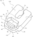
Fig. 2] Fig. 2 is a schematic perspective view of fastener element according to an aspect of the present disclosure. - [
Fig. 3] Fig. 3 is a schematic front or rear view of fastener element according to an aspect of the present disclosure. - [
Fig. 4] Fig. 4 is a schematic cross-sectional view of fastener element taken along an alternate long and short dashed line inFig. 3 . - [
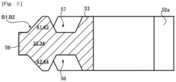
Fig. 5] Fig. 5 is a schematic cross-sectional view of conventional fastener element corresponding toFig. 4 . - [
Fig. 6] Fig. 6 is a schematic view illustrating arrangement of fastener elements inside of a slider according to an aspect of the present disclosure, a pair of left and right fastener elements have come into initial contact at an initial contact point away from a coupling pillar of the slider by a first distance. - [
Fig. 7] Fig. 7 is a schematic view illustrating arrangement of fastener elements inside of a slider according to an aspect of the present disclosure, illustrating that a pair of left and right fastener elements immediately anterior to those disclosed inFig. 6 have come into initial contact as the slider has been moved forward. - [
Fig. 8] Fig. 8 is a schematic view illustrating arrangement of conventional fastener elements inside of a slider. - Hereinafter, various embodiments and features will be described with reference to
Figs. 1 to 8 . A skilled person would be able to combine respective embodiments and/or respective features without requiring excess descriptions, and would appreciate synergistic effects of such combinations. Overlapping descriptions among the embodiments are basically omitted. Referenced drawings aim mainly for describing inventions and are simplified for the sake of convenience of illustration. The respective features should be appreciated as universal features not only effective to slide fasteners presently presented but also effective to other various slide fasteners not presented in the present specification. - In the present specification, front-rear direction would be understood based on movement of
slider 9. Direction of movement of theslider 9 forclosing fastener stringers 3 and 4 is equal to a forward direction. Direction of movement of theslider 9 for openingfastener stringers 3 and 4 is equal to a rearward direction. Left-right direction would be understood based onfastener stringers 3 and 4 to be closed and opened by theslider 9. Up-down direction is orthogonal to the front-rear direction and the left-right direction and, for example, is orthogonal to tape faces of a fastener tape which define a thickness of the fastener tape. - As shown in
Fig. 1 , aslide fastener 1 has left andright fastener stringers 3 and 4, and aslider 9 that moves forward to close the left andright fastener stringers 3 and 4 and moves rearward to open the left andright fastener stringers 3 and 4. The fastener stringer 3, 4 has afastener tape fastener elements fastener elements edges fastener tapes fastener tapes front stops fastener element right fastener stringers 3 and 4 are coupled by a commonrear stop 83 at the rear ends of the arrays of thefastener elements front stop rear stop 83 can be omitted. The slide fastener should not be limited to one disclosed inFig. 1 . The present invention can be adapted to a conceal slide fastener in which fastener elements are concealed by fastener tape not to be seen. - The
fastener tape fastener tape fastener tape edges fastener tapes fastener elements fastener tape - The
fastener element fastener elements fastener elements edge 13, 14 (e.g. the core thread there) of thefastener tape fastener elements fastener elements fastener elements fastener elements edge 13, 14 (e.g. the core thread there) of thefastener tape fastener elements - As shown in
Figs. 2-4 , thefastener element attachment base edge fastener tape head edge fastener tape attachment base legs edge fastener tape coupling portion 53 to which the base ends of thelegs legs coupling portion 53 in the left-right direction outwardly (i.e. a direction directed away from a center line CL of the slide fastener in the left-right direction) so that a space is defined between thelegs edge 13, 14 (e.g. the core thread there) of thefastener tape legs projections edge 13, 14 (e.g. the core thread) from moving out of the accommodating space between thelegs - The
head attachment base head front protrusion rear protrusion front protrusion 41 and therear protrusion 42 are protruded to the opposite side on the same axis. The same holds true to thefront protrusion 43 and therear protrusion 44. Thehead plate portion 56 having a thickness defined by afront surface 56a on which thefront protrusion rear surface 56b on which therear protrusion attachment base 31,32 (in the front-rear direction). Afront recess 57 is formed between the front protrusion 41 (similarly the front protrusion 43) and theattachment base 31, and arear recess 58 is formed between the rear protrusion 42 (similarly the rear protrusion 44) and theattachment base 31. Thefront protrusion rear protrusion attachment base end surface 56c of theplate portion 56. - As shown in
Fig. 4 , the engagement protrusion B1 (similarly the engagement protrusion B2) has nearer slopedsurfaces 61 on the front and rear sides which diverge from each other as being away from theattachment base attachment base top portions 63 on the front and rear sides formed between the nearer slopedsurface 61 and the farther slopedsurface 62. Thefront protrusion top portion 63 on the front side, the nearer slopedsurface 61 and the farther slopedsurface 62 on the front side which approach each other as being away from theplate portion 56 of thehead rear protrusion top portion 63 on the rear side, the nearer slopedsurface 61 and the farther slopedsurface 62 on the rear side which approach each other as being away from theplate portion 56 of thehead - The farther sloped
surface 62 is sectioned into pluralsloped regions region 62a situated closer to thetop portion 63 is inclined more gently than the slopedregion 62b situated farther from thetop portion 63. As would be understood by comparingFig. 4 (fastener element of the present embodiment) andFig. 5 (conventional fastener element), the slopedregion 62a situated closer to thetop portion 63 is gently angled owing to the division of the farther slopedsurface 62 into the differently angledsloped regions slider 9 as would be understood from the following descriptions. Note that the inclination angle of the slopedregion 62b is equal to the inclination angle of the nearer slopedsurface 61. Thetop portion 63 includes a flat surface that extends evenly along a direction thehead edge fastener tape slider 9. - The
fastener element walls rear protrusion 42 of anotherfastener element Figs. 3 and 4 ). Likewise, thefastener element walls front protrusion 41 of anotherfastener element Fig. 4 ). Thewall attachment base front recess 57 and therear recess 58 are gradually increased as being away from theattachment base - The
slider 9 is configured to engage and disengage the left andright fastener elements slider 9 may be metal or plastic or ceramic for example, but may be a composite of these materials. As seen fromFigs. 1 and6 , theslider 9 has atop wing 91, a bottom wing 92, and acoupling pillar 93. Left and right front-mouths coupling pillar 93 and a rear-mouth 95 is arranged at the opposite side of thefront mouths slider 9 matches the center line CL of theslide fastener 1. Thecoupling pillar 93 has a cross-sectional shape in which the width in the left-right direction is gradually reduced rearward. Therefore, thecoupling pillar 93 has left and right guide surfaces 93m and 93n that approach each other rearward. Theend surface 56c of theplate portion 56 of thehead fastener element guide surface - Flanges (not-illustrated) protruding downward may be arranged at the left and right side-edges of the
top wing 91 to restrict the displacement in the left-right direction of the left andright fastener elements flanges Fig. 6 ). The flange (not-illustrated) at the left side-edge of thetop wing 91 and theflange 96m at the left side-edge of the bottom wing 92 are opposed, defining an insertion space for theleft fastener tape 11. The flange (not-illustrated) at the right side-edge of thetop wing 91 and theflange 96n at the right side-edge of the bottom wing 92 are opposed, defining an insertion space for theright fastener tape 12. - As understandable from
Figs. 6 and7 , the left andright fastener elements front protrusion rear protrusion slider 9 as theslider 9 moves forward. The initial contact is caused when theslider 9 moves forward. As theslider 9 moves forward, the left andright fastener elements slider 9 via thefront mouths slider 9. The left andright fastener elements slider 9 via thefront mouths coupling pillar 93 between them. As theslider 9 further moves forward, these left andright fastener elements mouths right fastener elements coupling pillar 93 by a predetermined distance, these left andright fastener elements rear protrusion 42 of thefastener element 21 and thefront protrusion 43 of the fastener element 22 (SeeFig. 6 ). Likewise, the initial contact can be caused between thefront protrusion 41 of thefastener element 21 and therear protrusion 44 of the fastener element 22 (SeeFig. 7 ). As a result of this, the left andright fastener elements front protrusion rear protrusion slider 9 as theslider 9 moves forward, as described above. - In the present embodiment, as depicted in
Fig. 6 , when a given pair of left and right fastener elements E1 and E2 included in the left andright fastener elements rear protrusion 42 of the anterior fastener element E1 of the pair of fastener elements E1 and E2 and thefront protrusion 43 of the posterior fastener element E2 of the pair of fastener elements E1 and E2, therear protrusion 44 of the posterior fastener element E2 is not in contact with thefront protrusion 41 of a fastener element E3 with which the posterior fastener element E2 came into initial contact at itsrear protrusion 44 in advance (in other words, a fastener element E3 immediately posterior to the posterior fastener element E2). For the engagement between the fastener elements E1 and E2, there is a need for therear protrusion 42 of the anterior fastener element E1 to move across thefront protrusion 43 of the posterior fastener element E2. As described above, therear protrusion 44 of the posterior fastener element E2 is not in contact with thefront protrusion 41 of the fastener element E3, namely there is a space between them. It is thus facilitated that the posterior fastener element E2 moves more freely, allowing therear protrusion 42 of the anterior fastener element E1 to more easily move across thefront protrusion 43 of the posterior fastener element E2. This allows the reduction of resistance for sliding theslider 9 forward. - The same descriptions as in
Fig. 6 would be applicable toFig. 7 . As depicted inFig. 7 , when a given pair of left and right fastener elements E0 and E1 come into initial contact on therear protrusion 44 of the anterior fastener element E0 and thefront protrusion 41 of the posterior fastener element E1, therear protrusion 42 of the posterior fastener element E1 is not in contact with thefront protrusion 43 of the fastener element E2 with which the posterior fastener element E1 came into initial contact at itsrear protrusion 42 in advance (i.e. the initial contact inFig. 6 ). There is a space between therear protrusion 42 of the fastener element E1 and thefront protrusion 43 of the fastener element E2, and the fastener element E1 can move more freely, allowing the reduction of resistance for sliding theslider 9 forward. As would be understood by comparingFigs. 6 and7 , as theslider 9 moves forward, a respective one of the fastener elements comes into initial contact with, two times in total at different time points, two fastener elements which are adjacently arranged at the opposite side in the left-right direction. - In some cases, for a purpose of effective reduction of resistance for sliding the
slider 9, therear protrusion 42 of the fastener element E1 and thefront protrusion 43 of the fastener element E2 come into contact on their respectivesloped regions 62a of the farther sloped surfaces 62. Likewise, in the case ofFig. 7 , therear protrusion 44 of the fastener element E0 and thefront protrusion 41 of the fastener element E1 come into contact on their respectivesloped regions 62a of the farther sloped surfaces 62. The rear protrusion slides on the slopedregion 62a and moves across thetop portion 63 of the front protrusion, and then enters into thefront recess 57. The front protrusion slides on the slopedregion 62a and moves across thetop portion 63 of the rear protrusion, and then enters into therear recess 58. The front protrusion and the rear recess are fitted and the rear protrusion and the front recess are fitted, thereby the left and right fastener elements E1 and E2 are engaged and the strength ofslide fastener 1 would be ensured against a lateral pulling force. In cases where thewalls slide fastener 1 against thrust in the up-down direction would be ensured. - In some cases, the fastener elements E1 and E2 come into initial contact on the center line CL of
slider 9. This initial contact point P1 is away from the rear end of thecoupling pillar 93 by a first distance D1. An intersection point P2 between the center line Cl of theslider 9 and the rear protrusion 44 (the slopedregion 62a of the farther sloped surface 62) of the fastener element E2 is away from the rear end of thecoupling pillar 93 by a second distance D2 (SeeFig. 6 ). An intersection point P3 between the center line CL of theslider 9 and the front protrusion 41 (the slopedregion 62a of the farther slopedsurface 62 described above) of the fastener element E3 is away from the rear end of thecoupling pillar 93 by a third distance D3 (SeeFig. 6 ). The intersection points P2 and P3 are intersection points at the time of initial contact between thefastener elements E 1 and E2. Equation of D1<D2<D3 is satisfied. The equation of D2<D3 indicates the existence of space between therear protrusion 44 of the fastener element E2 and thefront protrusion 41 of the fastener element E3. - The fastener elements E1 and E2 (see
Fig. 6 ) which have come into initial contact at the initial contact point away from the rear end of thecoupling pillar 93 by the first distance D1 would cease to be in contact before the next pair of fastener elements E0 and E1 for initial contact come into initial contact (seeFig. 7 ). When the pair of fastener elements E0 and E1 for the next initial contact come into initial contact, the pair of fastener elements E1 and E2 for the previous initial contact are not in contact (in more particular, there is a space between therear protrusion 42 of the fastener element E1 and thefront protrusion 43 of the fastener element E2), and the fastener element E1 can move more freely, thus reducing the resistance for sliding theslider 9. - A design can be employed which, when the pair of left and right fastener elements E0 and E1 come into initial contact on the
rear protrusion 44 of the anterior fastener element E0 thereof and thefront protrusion 41 of the posterior fastener element E1 thereof inside of theslider 9, allows therear protrusion 42 of the posterior fastener element E1 not to be in contact with thefront protrusion 43 of the fastener element E2 with which the posterior fastener element E1 came into initial contact at itsrear protrusion 42 in advance. This method of designing may include determining the initial contact position for thefastener elements attachment base front protrusion 41 and therear protrusion 42 for a purpose of adjustment of the first distance D1 or smooth engagement between the fastener elements, and may section the farther slopedsurface 62 as described above, for example. This method of designing can be performed by computer software. - Based on the above teachings, a skilled person in the art would be able to add various modifications to the respective embodiments. Reference numerals in Claims are just for reference and should not be referred for the purpose of narrowly construing the scope of claims.
-
- 1
- Slide fastener
- 9
- Slider
- 11
- Fastener tape
- 12
- Fastener tape
- 13
- Side-edge
- 14
- Side-edge
- 21
- Fastener element
- 22
- Fastener element
- 31
- Attachment base
- 32
- Attachment base
- 33
- Head
- 34
- Head
- 41
- Front protrusion
- 42
- Rear protrusion
- 43
- Front protrusion
- 44
- Rear protrusion
- 56
- Plate portion
- B1
- Engagement protrusion
- B2
- Engagement protrusion
Claims (7)
- A slide fastener comprising:left and right fastener stringers (3,4) with fastener elements (21,22) attached to opposed side-edges (13,14) of fastener tapes (11,12), each fastener element (21,22) including an attachment base (31,32) secured to the side-edge (13,14) of the fastener tape (11,12) and a head (33,34) having an engagement protrusion (B1,B2) positioned away from said side-edge (13,14) of the fastener tape (11,12), and the engagement protrusion (B1,B2) including a front protrusion (41,43) protruding forward and a rear protrusion (42,44) protruding rearward; anda slider (9) that moves forward to engage left and right fastener elements (21,22) included in the left and right fastener stringers (3,4), the left and right fastener elements (21,22) coming into initial contact on the front protrusion (41,43) and the rear protrusion (42,44) alternately inside of the slider (9) as the slider (9) moves forward,when a given pair of left and right fastener elements (EO,E1) included in the left and right fastener elements (21,22) come into initial contact on the rear protrusion (44) of an anterior fastener element (E0) of the given pair of left and right fastener elements (EO,E1) and the front protrusion (41) of a posterior fastener element (E 1) of the given pair of left and right fastener elements (E0,E1), the rear protrusion (42) of the posterior fastener element (E1) is not in contact with the front protrusion (43) of a fastener element (E2) immediately posterior to said posterior fastener element (E1).
- The slide fastener of Claim 1, wherein the engagement protrusion (B1,B2) includes:nearer sloped surfaces (61) that diverge from each other as being away from the attachment base (31,32);farther sloped surfaces (62) that approach each other as being away from the attachment base (31,32); andtop portions (63) each of which being formed between the nearer sloped surface (61) and the farther sloped surface (62), and whereinthe farther sloped surface (62) is sectioned into plural sloped regions (62a,62b) having different angles of inclination, and the sloped region (62a) situated closer to the top portion (63) is inclined more gently than the sloped region (62b) situated farther from the top portion (63).
- The slide fastener of Claim 2, wherein the left and right fastener elements (21,22) come into initial contact on the respective sloped regions (62a) situated closer to the top portion (63).
- The slide fastener of Claim 2 or 3, wherein the top portion (63) includes a flat surface that extends evenly along a direction the head (33,34) protrudes from the side-edge (13,14) of the fastener tape (11,12).
- The slide fastener of any one of Claims 1-4, wherein an initial contact position (P1) of the left and right fastener elements (21,22) is on a center line of the slider (9).
- The slide fastener of any one of Claims 1-5, wherein the head (33,34) includes a plate portion (56) having a thickness defined by a front surface (56a) on which the front protrusion (41,43) is arranged and a rear surface (56b) on which the rear protrusion (42,44) is arranged, said thickness being less than a thickness of the attachment base (31,32), a front recess (57) formed between the front protrusion (41,43) and the attachment base (31,32), and a rear recess (58) formed between the rear protrusion (42,44) and the attachment base (31,32).
- A method of designing a slide fastener, the slide fastener comprising:left and right fastener stringers (3,4) with fastener elements (21,22) attached to side-edges (13,14) of fastener tapes (11,12), each fastener element (21,22) including an attachment base (31,32) secured to the side-edge (13,14) of the fastener tape (11,12) and a head (33,34) having an engagement protrusion (B1,B2) positioned away from said side-edge (13,14) of the fastener tape (11,12), and the engagement protrusion (B1,B2) including a front protrusion (41,43) protruding forward and a rear protrusion (42,44) protruding rearward; anda slider (9) that moves forward to engage left and right fastener elements (21,22) included in the left and right fastener stringers (3,4), the left and right fastener elements (21,22) coming into initial contact on the front protrusion (41,43) and the rear protrusion (42,44) alternately as the slider (9) moves forward, the method comprising:
when a given pair of left and right fastener elements (EO,E1) included in the left and right fastener elements (21,22) come into initial contact on the rear protrusion (44) of an anterior fastener element (E0) of the given pair of left and right fastener elements (EO,E1) and the front protrusion (41) of a posterior fastener element (E 1) of the given pair of left and right fastener elements (E0,E1) inside of the slider (9), allowing the rear protrusion (42) of the posterior fastener element (E1) to be not in contact with the front protrusion (43) of a fastener element (E2) immediately posterior to said posterior fastener element (E1).
Applications Claiming Priority (1)
| Application Number | Priority Date | Filing Date | Title |
|---|---|---|---|
| PCT/JP2020/014675 WO2021199203A1 (en) | 2020-03-30 | 2020-03-30 | Slide fastener and design method thereof |
Publications (3)
| Publication Number | Publication Date |
|---|---|
| EP4129112A1 true EP4129112A1 (en) | 2023-02-08 |
| EP4129112A4 EP4129112A4 (en) | 2023-05-03 |
| EP4129112B1 EP4129112B1 (en) | 2024-06-19 |
Family
ID=77927825
Family Applications (1)
| Application Number | Title | Priority Date | Filing Date |
|---|---|---|---|
| EP20929605.2A Active EP4129112B1 (en) | 2020-03-30 | 2020-03-30 | Slide fastener and design method thereof |
Country Status (4)
| Country | Link |
|---|---|
| EP (1) | EP4129112B1 (en) |
| JP (1) | JP7274044B2 (en) |
| CN (1) | CN115279225B (en) |
| WO (1) | WO2021199203A1 (en) |
Families Citing this family (1)
| Publication number | Priority date | Publication date | Assignee | Title |
|---|---|---|---|---|
| UA128686C2 (en) * | 2022-10-19 | 2024-09-25 | Олександр Павлович Петренко | Zipper |
Family Cites Families (7)
| Publication number | Priority date | Publication date | Assignee | Title |
|---|---|---|---|---|
| JPH0122505Y2 (en) * | 1984-09-14 | 1989-07-05 | ||
| JP4749389B2 (en) * | 2007-06-20 | 2011-08-17 | Ykk株式会社 | Double-sided tooth for slide fastener |
| ES2359533T3 (en) * | 2007-07-10 | 2011-05-24 | Ykk Corporation | DOUBLE FACE METAL ELEMENT AND ZIPPER CLOSURE. |
| ES2666661T3 (en) | 2008-04-14 | 2018-05-07 | Ykk Corporation | One-side metal teeth and bi-directional zip closure |
| EP2564720B1 (en) * | 2010-04-28 | 2017-09-20 | YKK Corporation | Metal double-sided tooth and slide fastener |
| JP2015123111A (en) | 2013-12-25 | 2015-07-06 | Ykk株式会社 | Slide fastener |
| EP3834649B1 (en) * | 2018-08-06 | 2026-03-04 | YKK Corporation | Element and slide fastener |
-
2020
- 2020-03-30 CN CN202080095697.9A patent/CN115279225B/en active Active
- 2020-03-30 EP EP20929605.2A patent/EP4129112B1/en active Active
- 2020-03-30 WO PCT/JP2020/014675 patent/WO2021199203A1/en not_active Ceased
- 2020-03-30 JP JP2022512937A patent/JP7274044B2/en active Active
Also Published As
| Publication number | Publication date |
|---|---|
| CN115279225B (en) | 2025-08-26 |
| JP7274044B2 (en) | 2023-05-15 |
| EP4129112A4 (en) | 2023-05-03 |
| WO2021199203A1 (en) | 2021-10-07 |
| JPWO2021199203A1 (en) | 2021-10-07 |
| EP4129112B1 (en) | 2024-06-19 |
| CN115279225A (en) | 2022-11-01 |
Similar Documents
| Publication | Publication Date | Title |
|---|---|---|
| TWI468122B (en) | Zipper | |
| EP2425735B1 (en) | Slider for slide fastener and quick open-type slide fastener | |
| US10874179B2 (en) | Rotation mechanism of separable stopper for slide fastener and slide fastener including same | |
| EP2460430B1 (en) | Slide fastener | |
| EP2904922B1 (en) | Slide fastener | |
| EP2014188B1 (en) | Metallic double-sided element and slide fastener | |
| WO2012127688A1 (en) | Slide fastener and slider with simple locking mechanism | |
| JP3214476U (en) | Slide fastener for slide fastener and slide fastener | |
| CN113795173B (en) | zipper | |
| EP4238445B1 (en) | Slider for reverse opening-type slide fastener | |
| EP4129112B1 (en) | Slide fastener and design method thereof | |
| CN220140965U (en) | Zipper fastener | |
| US9750313B2 (en) | Slider for slide fastener, and slide fastener | |
| US20260108023A1 (en) | Two-way separator | |
| CN222982584U (en) | Slider for slide fastener | |
| US20260076456A1 (en) | Slide fastener | |
| US20250261727A1 (en) | Slider and slide fastener | |
| CN114641219B (en) | zipper | |
| WO2025158504A1 (en) | Slider for slide fastener and method for operating same | |
| CN121987015A (en) | Zipper teeth connecting belt | |
| CN119630308A (en) | Zippers and zipper opening elements | |
| WO2026013887A1 (en) | Slide fastener and method for producing separable bottom stop box for slide fastener | |
| CN119173173A (en) | Method for manufacturing slide fastener and fastener stringer for slide fastener | |
| WO2022118404A1 (en) | Zipper slider |
Legal Events
| Date | Code | Title | Description |
|---|---|---|---|
| STAA | Information on the status of an ep patent application or granted ep patent |
Free format text: STATUS: THE INTERNATIONAL PUBLICATION HAS BEEN MADE |
|
| PUAI | Public reference made under article 153(3) epc to a published international application that has entered the european phase |
Free format text: ORIGINAL CODE: 0009012 |
|
| STAA | Information on the status of an ep patent application or granted ep patent |
Free format text: STATUS: REQUEST FOR EXAMINATION WAS MADE |
|
| 17P | Request for examination filed |
Effective date: 20220727 |
|
| AK | Designated contracting states |
Kind code of ref document: A1 Designated state(s): AL AT BE BG CH CY CZ DE DK EE ES FI FR GB GR HR HU IE IS IT LI LT LU LV MC MK MT NL NO PL PT RO RS SE SI SK SM TR |
|
| REG | Reference to a national code |
Ref legal event code: R079 Free format text: PREVIOUS MAIN CLASS: A44B0019440000 Ipc: A44B0019060000 Ref country code: DE Ref legal event code: R079 Ref document number: 602020032812 Country of ref document: DE Free format text: PREVIOUS MAIN CLASS: A44B0019440000 Ipc: A44B0019060000 |
|
| A4 | Supplementary search report drawn up and despatched |
Effective date: 20230403 |
|
| RIC1 | Information provided on ipc code assigned before grant |
Ipc: A44B 19/06 20060101AFI20230328BHEP |
|
| DAV | Request for validation of the european patent (deleted) | ||
| DAX | Request for extension of the european patent (deleted) | ||
| GRAP | Despatch of communication of intention to grant a patent |
Free format text: ORIGINAL CODE: EPIDOSNIGR1 |
|
| STAA | Information on the status of an ep patent application or granted ep patent |
Free format text: STATUS: GRANT OF PATENT IS INTENDED |
|
| INTG | Intention to grant announced |
Effective date: 20240209 |
|
| GRAS | Grant fee paid |
Free format text: ORIGINAL CODE: EPIDOSNIGR3 |
|
| P01 | Opt-out of the competence of the unified patent court (upc) registered |
Effective date: 20240404 |
|
| GRAA | (expected) grant |
Free format text: ORIGINAL CODE: 0009210 |
|
| STAA | Information on the status of an ep patent application or granted ep patent |
Free format text: STATUS: THE PATENT HAS BEEN GRANTED |
|
| AK | Designated contracting states |
Kind code of ref document: B1 Designated state(s): AL AT BE BG CH CY CZ DE DK EE ES FI FR GB GR HR HU IE IS IT LI LT LU LV MC MK MT NL NO PL PT RO RS SE SI SK SM TR |
|
| REG | Reference to a national code |
Ref country code: GB Ref legal event code: FG4D |
|
| REG | Reference to a national code |
Ref country code: CH Ref legal event code: EP |
|
| REG | Reference to a national code |
Ref country code: DE Ref legal event code: R096 Ref document number: 602020032812 Country of ref document: DE |
|
| PG25 | Lapsed in a contracting state [announced via postgrant information from national office to epo] |
Ref country code: BG Free format text: LAPSE BECAUSE OF FAILURE TO SUBMIT A TRANSLATION OF THE DESCRIPTION OR TO PAY THE FEE WITHIN THE PRESCRIBED TIME-LIMIT Effective date: 20240619 |
|
| PG25 | Lapsed in a contracting state [announced via postgrant information from national office to epo] |
Ref country code: HR Free format text: LAPSE BECAUSE OF FAILURE TO SUBMIT A TRANSLATION OF THE DESCRIPTION OR TO PAY THE FEE WITHIN THE PRESCRIBED TIME-LIMIT Effective date: 20240619 Ref country code: FI Free format text: LAPSE BECAUSE OF FAILURE TO SUBMIT A TRANSLATION OF THE DESCRIPTION OR TO PAY THE FEE WITHIN THE PRESCRIBED TIME-LIMIT Effective date: 20240619 |
|
| REG | Reference to a national code |
Ref country code: LT Ref legal event code: MG9D |
|
| PG25 | Lapsed in a contracting state [announced via postgrant information from national office to epo] |
Ref country code: GR Free format text: LAPSE BECAUSE OF FAILURE TO SUBMIT A TRANSLATION OF THE DESCRIPTION OR TO PAY THE FEE WITHIN THE PRESCRIBED TIME-LIMIT Effective date: 20240920 |
|
| REG | Reference to a national code |
Ref country code: NL Ref legal event code: MP Effective date: 20240619 |
|
| PG25 | Lapsed in a contracting state [announced via postgrant information from national office to epo] |
Ref country code: LV Free format text: LAPSE BECAUSE OF FAILURE TO SUBMIT A TRANSLATION OF THE DESCRIPTION OR TO PAY THE FEE WITHIN THE PRESCRIBED TIME-LIMIT Effective date: 20240619 |
|
| PG25 | Lapsed in a contracting state [announced via postgrant information from national office to epo] |
Ref country code: NO Free format text: LAPSE BECAUSE OF FAILURE TO SUBMIT A TRANSLATION OF THE DESCRIPTION OR TO PAY THE FEE WITHIN THE PRESCRIBED TIME-LIMIT Effective date: 20240919 Ref country code: LV Free format text: LAPSE BECAUSE OF FAILURE TO SUBMIT A TRANSLATION OF THE DESCRIPTION OR TO PAY THE FEE WITHIN THE PRESCRIBED TIME-LIMIT Effective date: 20240619 Ref country code: HR Free format text: LAPSE BECAUSE OF FAILURE TO SUBMIT A TRANSLATION OF THE DESCRIPTION OR TO PAY THE FEE WITHIN THE PRESCRIBED TIME-LIMIT Effective date: 20240619 Ref country code: GR Free format text: LAPSE BECAUSE OF FAILURE TO SUBMIT A TRANSLATION OF THE DESCRIPTION OR TO PAY THE FEE WITHIN THE PRESCRIBED TIME-LIMIT Effective date: 20240920 Ref country code: FI Free format text: LAPSE BECAUSE OF FAILURE TO SUBMIT A TRANSLATION OF THE DESCRIPTION OR TO PAY THE FEE WITHIN THE PRESCRIBED TIME-LIMIT Effective date: 20240619 Ref country code: BG Free format text: LAPSE BECAUSE OF FAILURE TO SUBMIT A TRANSLATION OF THE DESCRIPTION OR TO PAY THE FEE WITHIN THE PRESCRIBED TIME-LIMIT Effective date: 20240619 Ref country code: RS Free format text: LAPSE BECAUSE OF FAILURE TO SUBMIT A TRANSLATION OF THE DESCRIPTION OR TO PAY THE FEE WITHIN THE PRESCRIBED TIME-LIMIT Effective date: 20240919 |
|
| PG25 | Lapsed in a contracting state [announced via postgrant information from national office to epo] |
Ref country code: NL Free format text: LAPSE BECAUSE OF FAILURE TO SUBMIT A TRANSLATION OF THE DESCRIPTION OR TO PAY THE FEE WITHIN THE PRESCRIBED TIME-LIMIT Effective date: 20240619 |
|
| REG | Reference to a national code |
Ref country code: AT Ref legal event code: MK05 Ref document number: 1695343 Country of ref document: AT Kind code of ref document: T Effective date: 20240619 |
|
| PG25 | Lapsed in a contracting state [announced via postgrant information from national office to epo] |
Ref country code: NL Free format text: LAPSE BECAUSE OF FAILURE TO SUBMIT A TRANSLATION OF THE DESCRIPTION OR TO PAY THE FEE WITHIN THE PRESCRIBED TIME-LIMIT Effective date: 20240619 |
|
| PG25 | Lapsed in a contracting state [announced via postgrant information from national office to epo] |
Ref country code: PT Free format text: LAPSE BECAUSE OF FAILURE TO SUBMIT A TRANSLATION OF THE DESCRIPTION OR TO PAY THE FEE WITHIN THE PRESCRIBED TIME-LIMIT Effective date: 20241021 |
|
| PG25 | Lapsed in a contracting state [announced via postgrant information from national office to epo] |
Ref country code: PT Free format text: LAPSE BECAUSE OF FAILURE TO SUBMIT A TRANSLATION OF THE DESCRIPTION OR TO PAY THE FEE WITHIN THE PRESCRIBED TIME-LIMIT Effective date: 20241021 |
|
| PG25 | Lapsed in a contracting state [announced via postgrant information from national office to epo] |
Ref country code: PL Free format text: LAPSE BECAUSE OF FAILURE TO SUBMIT A TRANSLATION OF THE DESCRIPTION OR TO PAY THE FEE WITHIN THE PRESCRIBED TIME-LIMIT Effective date: 20240619 |
|
| PG25 | Lapsed in a contracting state [announced via postgrant information from national office to epo] |
Ref country code: EE Free format text: LAPSE BECAUSE OF FAILURE TO SUBMIT A TRANSLATION OF THE DESCRIPTION OR TO PAY THE FEE WITHIN THE PRESCRIBED TIME-LIMIT Effective date: 20240619 |
|
| PG25 | Lapsed in a contracting state [announced via postgrant information from national office to epo] |
Ref country code: IS Free format text: LAPSE BECAUSE OF FAILURE TO SUBMIT A TRANSLATION OF THE DESCRIPTION OR TO PAY THE FEE WITHIN THE PRESCRIBED TIME-LIMIT Effective date: 20241019 Ref country code: AT Free format text: LAPSE BECAUSE OF FAILURE TO SUBMIT A TRANSLATION OF THE DESCRIPTION OR TO PAY THE FEE WITHIN THE PRESCRIBED TIME-LIMIT Effective date: 20240619 |
|
| PG25 | Lapsed in a contracting state [announced via postgrant information from national office to epo] |
Ref country code: CZ Free format text: LAPSE BECAUSE OF FAILURE TO SUBMIT A TRANSLATION OF THE DESCRIPTION OR TO PAY THE FEE WITHIN THE PRESCRIBED TIME-LIMIT Effective date: 20240619 |
|
| PG25 | Lapsed in a contracting state [announced via postgrant information from national office to epo] |
Ref country code: SK Free format text: LAPSE BECAUSE OF FAILURE TO SUBMIT A TRANSLATION OF THE DESCRIPTION OR TO PAY THE FEE WITHIN THE PRESCRIBED TIME-LIMIT Effective date: 20240619 Ref country code: RO Free format text: LAPSE BECAUSE OF FAILURE TO SUBMIT A TRANSLATION OF THE DESCRIPTION OR TO PAY THE FEE WITHIN THE PRESCRIBED TIME-LIMIT Effective date: 20240619 |
|
| PG25 | Lapsed in a contracting state [announced via postgrant information from national office to epo] |
Ref country code: SM Free format text: LAPSE BECAUSE OF FAILURE TO SUBMIT A TRANSLATION OF THE DESCRIPTION OR TO PAY THE FEE WITHIN THE PRESCRIBED TIME-LIMIT Effective date: 20240619 Ref country code: ES Free format text: LAPSE BECAUSE OF FAILURE TO SUBMIT A TRANSLATION OF THE DESCRIPTION OR TO PAY THE FEE WITHIN THE PRESCRIBED TIME-LIMIT Effective date: 20240619 |
|
| PG25 | Lapsed in a contracting state [announced via postgrant information from national office to epo] |
Ref country code: SM Free format text: LAPSE BECAUSE OF FAILURE TO SUBMIT A TRANSLATION OF THE DESCRIPTION OR TO PAY THE FEE WITHIN THE PRESCRIBED TIME-LIMIT Effective date: 20240619 Ref country code: SK Free format text: LAPSE BECAUSE OF FAILURE TO SUBMIT A TRANSLATION OF THE DESCRIPTION OR TO PAY THE FEE WITHIN THE PRESCRIBED TIME-LIMIT Effective date: 20240619 Ref country code: RO Free format text: LAPSE BECAUSE OF FAILURE TO SUBMIT A TRANSLATION OF THE DESCRIPTION OR TO PAY THE FEE WITHIN THE PRESCRIBED TIME-LIMIT Effective date: 20240619 Ref country code: PL Free format text: LAPSE BECAUSE OF FAILURE TO SUBMIT A TRANSLATION OF THE DESCRIPTION OR TO PAY THE FEE WITHIN THE PRESCRIBED TIME-LIMIT Effective date: 20240619 Ref country code: IS Free format text: LAPSE BECAUSE OF FAILURE TO SUBMIT A TRANSLATION OF THE DESCRIPTION OR TO PAY THE FEE WITHIN THE PRESCRIBED TIME-LIMIT Effective date: 20241019 Ref country code: ES Free format text: LAPSE BECAUSE OF FAILURE TO SUBMIT A TRANSLATION OF THE DESCRIPTION OR TO PAY THE FEE WITHIN THE PRESCRIBED TIME-LIMIT Effective date: 20240619 Ref country code: EE Free format text: LAPSE BECAUSE OF FAILURE TO SUBMIT A TRANSLATION OF THE DESCRIPTION OR TO PAY THE FEE WITHIN THE PRESCRIBED TIME-LIMIT Effective date: 20240619 Ref country code: CZ Free format text: LAPSE BECAUSE OF FAILURE TO SUBMIT A TRANSLATION OF THE DESCRIPTION OR TO PAY THE FEE WITHIN THE PRESCRIBED TIME-LIMIT Effective date: 20240619 Ref country code: AT Free format text: LAPSE BECAUSE OF FAILURE TO SUBMIT A TRANSLATION OF THE DESCRIPTION OR TO PAY THE FEE WITHIN THE PRESCRIBED TIME-LIMIT Effective date: 20240619 |
|
| REG | Reference to a national code |
Ref country code: DE Ref legal event code: R097 Ref document number: 602020032812 Country of ref document: DE |
|
| PG25 | Lapsed in a contracting state [announced via postgrant information from national office to epo] |
Ref country code: DK Free format text: LAPSE BECAUSE OF FAILURE TO SUBMIT A TRANSLATION OF THE DESCRIPTION OR TO PAY THE FEE WITHIN THE PRESCRIBED TIME-LIMIT Effective date: 20240619 |
|
| PLBE | No opposition filed within time limit |
Free format text: ORIGINAL CODE: 0009261 |
|
| STAA | Information on the status of an ep patent application or granted ep patent |
Free format text: STATUS: NO OPPOSITION FILED WITHIN TIME LIMIT |
|
| 26N | No opposition filed |
Effective date: 20250320 |
|
| PG25 | Lapsed in a contracting state [announced via postgrant information from national office to epo] |
Ref country code: SE Free format text: LAPSE BECAUSE OF FAILURE TO SUBMIT A TRANSLATION OF THE DESCRIPTION OR TO PAY THE FEE WITHIN THE PRESCRIBED TIME-LIMIT Effective date: 20240619 |
|
| REG | Reference to a national code |
Ref country code: DE Ref legal event code: R119 Ref document number: 602020032812 Country of ref document: DE |
|
| PG25 | Lapsed in a contracting state [announced via postgrant information from national office to epo] |
Ref country code: MC Free format text: LAPSE BECAUSE OF FAILURE TO SUBMIT A TRANSLATION OF THE DESCRIPTION OR TO PAY THE FEE WITHIN THE PRESCRIBED TIME-LIMIT Effective date: 20240619 |
|
| REG | Reference to a national code |
Ref country code: CH Ref legal event code: H13 Free format text: ST27 STATUS EVENT CODE: U-0-0-H10-H13 (AS PROVIDED BY THE NATIONAL OFFICE) Effective date: 20251023 |
|
| PG25 | Lapsed in a contracting state [announced via postgrant information from national office to epo] |
Ref country code: LU Free format text: LAPSE BECAUSE OF NON-PAYMENT OF DUE FEES Effective date: 20250330 |
|
| GBPC | Gb: european patent ceased through non-payment of renewal fee |
Effective date: 20250330 |
|
| REG | Reference to a national code |
Ref country code: BE Ref legal event code: MM Effective date: 20250331 |
|
| PG25 | Lapsed in a contracting state [announced via postgrant information from national office to epo] |
Ref country code: DE Free format text: LAPSE BECAUSE OF NON-PAYMENT OF DUE FEES Effective date: 20251001 |
|
| PG25 | Lapsed in a contracting state [announced via postgrant information from national office to epo] |
Ref country code: GB Free format text: LAPSE BECAUSE OF NON-PAYMENT OF DUE FEES Effective date: 20250330 |
|
| PG25 | Lapsed in a contracting state [announced via postgrant information from national office to epo] |
Ref country code: FR Free format text: LAPSE BECAUSE OF NON-PAYMENT OF DUE FEES Effective date: 20250331 |
|
| PG25 | Lapsed in a contracting state [announced via postgrant information from national office to epo] |
Ref country code: BE Free format text: LAPSE BECAUSE OF NON-PAYMENT OF DUE FEES Effective date: 20250331 |
|
| PG25 | Lapsed in a contracting state [announced via postgrant information from national office to epo] |
Ref country code: CH Free format text: LAPSE BECAUSE OF NON-PAYMENT OF DUE FEES Effective date: 20250331 |
|
| PG25 | Lapsed in a contracting state [announced via postgrant information from national office to epo] |
Ref country code: IE Free format text: LAPSE BECAUSE OF NON-PAYMENT OF DUE FEES Effective date: 20250330 |
|
| PGFP | Annual fee paid to national office [announced via postgrant information from national office to epo] |
Ref country code: IT Payment date: 20260220 Year of fee payment: 7 |