EP4129034A1 - Agricultural machine - Google Patents
Agricultural machine Download PDFInfo
- Publication number
- EP4129034A1 EP4129034A1 EP21779728.1A EP21779728A EP4129034A1 EP 4129034 A1 EP4129034 A1 EP 4129034A1 EP 21779728 A EP21779728 A EP 21779728A EP 4129034 A1 EP4129034 A1 EP 4129034A1
- Authority
- EP
- European Patent Office
- Prior art keywords
- autonomous travel
- obstacle
- mode
- detector
- seat
- Prior art date
- Legal status (The legal status is an assumption and is not a legal conclusion. Google has not performed a legal analysis and makes no representation as to the accuracy of the status listed.)
- Granted
Links
Images


Classifications
-
- B—PERFORMING OPERATIONS; TRANSPORTING
- B60—VEHICLES IN GENERAL
- B60T—VEHICLE BRAKE CONTROL SYSTEMS OR PARTS THEREOF; BRAKE CONTROL SYSTEMS OR PARTS THEREOF, IN GENERAL; ARRANGEMENT OF BRAKING ELEMENTS ON VEHICLES IN GENERAL; PORTABLE DEVICES FOR PREVENTING UNWANTED MOVEMENT OF VEHICLES; VEHICLE MODIFICATIONS TO FACILITATE COOLING OF BRAKES
- B60T7/00—Brake-action initiating means
- B60T7/12—Brake-action initiating means for automatic initiation; for initiation not subject to will of driver or passenger
- B60T7/22—Brake-action initiating means for automatic initiation; for initiation not subject to will of driver or passenger initiated by contact of vehicle, e.g. bumper, with an external object, e.g. another vehicle, or by means of contactless obstacle detectors mounted on the vehicle
-
- A—HUMAN NECESSITIES
- A01—AGRICULTURE; FORESTRY; ANIMAL HUSBANDRY; HUNTING; TRAPPING; FISHING
- A01B—SOIL WORKING IN AGRICULTURE OR FORESTRY; PARTS, DETAILS, OR ACCESSORIES OF AGRICULTURAL MACHINES OR IMPLEMENTS, IN GENERAL
- A01B69/00—Steering of agricultural machines or implements; Guiding agricultural machines or implements on a desired track
- A01B69/001—Steering by means of optical assistance, e.g. television cameras
-
- A—HUMAN NECESSITIES
- A01—AGRICULTURE; FORESTRY; ANIMAL HUSBANDRY; HUNTING; TRAPPING; FISHING
- A01B—SOIL WORKING IN AGRICULTURE OR FORESTRY; PARTS, DETAILS, OR ACCESSORIES OF AGRICULTURAL MACHINES OR IMPLEMENTS, IN GENERAL
- A01B69/00—Steering of agricultural machines or implements; Guiding agricultural machines or implements on a desired track
- A01B69/007—Steering or guiding of agricultural vehicles, e.g. steering of the tractor to keep the plough in the furrow
- A01B69/008—Steering or guiding of agricultural vehicles, e.g. steering of the tractor to keep the plough in the furrow automatic
-
- B—PERFORMING OPERATIONS; TRANSPORTING
- B60—VEHICLES IN GENERAL
- B60T—VEHICLE BRAKE CONTROL SYSTEMS OR PARTS THEREOF; BRAKE CONTROL SYSTEMS OR PARTS THEREOF, IN GENERAL; ARRANGEMENT OF BRAKING ELEMENTS ON VEHICLES IN GENERAL; PORTABLE DEVICES FOR PREVENTING UNWANTED MOVEMENT OF VEHICLES; VEHICLE MODIFICATIONS TO FACILITATE COOLING OF BRAKES
- B60T8/00—Arrangements for adjusting wheel-braking force to meet varying vehicular or ground-surface conditions, e.g. limiting or varying distribution of braking force
- B60T8/17—Using electrical or electronic regulation means to control braking
- B60T8/1755—Brake regulation specially adapted to control the stability of the vehicle, e.g. taking into account yaw rate or transverse acceleration in a curve
- B60T8/17558—Brake regulation specially adapted to control the stability of the vehicle, e.g. taking into account yaw rate or transverse acceleration in a curve specially adapted for collision avoidance or collision mitigation
-
- B—PERFORMING OPERATIONS; TRANSPORTING
- B60—VEHICLES IN GENERAL
- B60W—CONJOINT CONTROL OF VEHICLE SUB-UNITS OF DIFFERENT TYPE OR DIFFERENT FUNCTION; CONTROL SYSTEMS SPECIALLY ADAPTED FOR HYBRID VEHICLES; ROAD VEHICLE DRIVE CONTROL SYSTEMS FOR PURPOSES NOT RELATED TO THE CONTROL OF A PARTICULAR SUB-UNIT
- B60W30/00—Purposes of road vehicle drive control systems not related to the control of a particular sub-unit, e.g. of systems using conjoint control of vehicle sub-units
- B60W30/08—Active safety systems predicting or avoiding probable or impending collision or attempting to minimise its consequences
- B60W30/09—Taking automatic action to avoid collision, e.g. braking and steering
-
- B—PERFORMING OPERATIONS; TRANSPORTING
- B60—VEHICLES IN GENERAL
- B60W—CONJOINT CONTROL OF VEHICLE SUB-UNITS OF DIFFERENT TYPE OR DIFFERENT FUNCTION; CONTROL SYSTEMS SPECIALLY ADAPTED FOR HYBRID VEHICLES; ROAD VEHICLE DRIVE CONTROL SYSTEMS FOR PURPOSES NOT RELATED TO THE CONTROL OF A PARTICULAR SUB-UNIT
- B60W50/00—Details of control systems for road vehicle drive control not related to the control of a particular sub-unit, e.g. process diagnostic or vehicle driver interfaces
- B60W50/08—Interaction between the driver and the control system
- B60W50/14—Means for informing the driver, warning the driver or prompting a driver intervention
-
- B—PERFORMING OPERATIONS; TRANSPORTING
- B60—VEHICLES IN GENERAL
- B60W—CONJOINT CONTROL OF VEHICLE SUB-UNITS OF DIFFERENT TYPE OR DIFFERENT FUNCTION; CONTROL SYSTEMS SPECIALLY ADAPTED FOR HYBRID VEHICLES; ROAD VEHICLE DRIVE CONTROL SYSTEMS FOR PURPOSES NOT RELATED TO THE CONTROL OF A PARTICULAR SUB-UNIT
- B60W60/00—Drive control systems specially adapted for autonomous road vehicles
- B60W60/001—Planning or execution of driving tasks
- B60W60/0015—Planning or execution of driving tasks specially adapted for safety
-
- G—PHYSICS
- G05—CONTROLLING; REGULATING
- G05D—SYSTEMS FOR CONTROLLING OR REGULATING NON-ELECTRIC VARIABLES
- G05D1/00—Control of position, course, altitude or attitude of land, water, air or space vehicles, e.g. using automatic pilots
- G05D1/0055—Control of position, course, altitude or attitude of land, water, air or space vehicles, e.g. using automatic pilots with safety arrangements
- G05D1/0061—Control of position, course, altitude or attitude of land, water, air or space vehicles, e.g. using automatic pilots with safety arrangements for transition from automatic pilot to manual pilot and vice versa
-
- G—PHYSICS
- G05—CONTROLLING; REGULATING
- G05D—SYSTEMS FOR CONTROLLING OR REGULATING NON-ELECTRIC VARIABLES
- G05D1/00—Control of position, course, altitude or attitude of land, water, air or space vehicles, e.g. using automatic pilots
- G05D1/02—Control of position or course in two dimensions
- G05D1/021—Control of position or course in two dimensions specially adapted to land vehicles
- G05D1/0212—Control of position or course in two dimensions specially adapted to land vehicles with means for defining a desired trajectory
- G05D1/0214—Control of position or course in two dimensions specially adapted to land vehicles with means for defining a desired trajectory in accordance with safety or protection criteria, e.g. avoiding hazardous areas
-
- G—PHYSICS
- G05—CONTROLLING; REGULATING
- G05D—SYSTEMS FOR CONTROLLING OR REGULATING NON-ELECTRIC VARIABLES
- G05D1/00—Control of position, course, altitude or attitude of land, water, air or space vehicles, e.g. using automatic pilots
- G05D1/02—Control of position or course in two dimensions
- G05D1/021—Control of position or course in two dimensions specially adapted to land vehicles
- G05D1/0231—Control of position or course in two dimensions specially adapted to land vehicles using optical position detecting means
- G05D1/0238—Control of position or course in two dimensions specially adapted to land vehicles using optical position detecting means using obstacle or wall sensors
- G05D1/024—Control of position or course in two dimensions specially adapted to land vehicles using optical position detecting means using obstacle or wall sensors in combination with a laser
-
- G—PHYSICS
- G05—CONTROLLING; REGULATING
- G05D—SYSTEMS FOR CONTROLLING OR REGULATING NON-ELECTRIC VARIABLES
- G05D1/00—Control of position, course, altitude or attitude of land, water, air or space vehicles, e.g. using automatic pilots
- G05D1/60—Intended control result
- G05D1/617—Safety or protection, e.g. defining protection zones around obstacles or avoiding hazards
-
- B—PERFORMING OPERATIONS; TRANSPORTING
- B60—VEHICLES IN GENERAL
- B60T—VEHICLE BRAKE CONTROL SYSTEMS OR PARTS THEREOF; BRAKE CONTROL SYSTEMS OR PARTS THEREOF, IN GENERAL; ARRANGEMENT OF BRAKING ELEMENTS ON VEHICLES IN GENERAL; PORTABLE DEVICES FOR PREVENTING UNWANTED MOVEMENT OF VEHICLES; VEHICLE MODIFICATIONS TO FACILITATE COOLING OF BRAKES
- B60T2201/00—Particular use of vehicle brake systems; Special systems using also the brakes; Special software modules within the brake system controller
- B60T2201/02—Active or adaptive cruise control system; Distance control
- B60T2201/022—Collision avoidance systems
-
- B—PERFORMING OPERATIONS; TRANSPORTING
- B60—VEHICLES IN GENERAL
- B60T—VEHICLE BRAKE CONTROL SYSTEMS OR PARTS THEREOF; BRAKE CONTROL SYSTEMS OR PARTS THEREOF, IN GENERAL; ARRANGEMENT OF BRAKING ELEMENTS ON VEHICLES IN GENERAL; PORTABLE DEVICES FOR PREVENTING UNWANTED MOVEMENT OF VEHICLES; VEHICLE MODIFICATIONS TO FACILITATE COOLING OF BRAKES
- B60T2201/00—Particular use of vehicle brake systems; Special systems using also the brakes; Special software modules within the brake system controller
- B60T2201/10—Automatic or semi-automatic parking aid systems
-
- B—PERFORMING OPERATIONS; TRANSPORTING
- B60—VEHICLES IN GENERAL
- B60W—CONJOINT CONTROL OF VEHICLE SUB-UNITS OF DIFFERENT TYPE OR DIFFERENT FUNCTION; CONTROL SYSTEMS SPECIALLY ADAPTED FOR HYBRID VEHICLES; ROAD VEHICLE DRIVE CONTROL SYSTEMS FOR PURPOSES NOT RELATED TO THE CONTROL OF A PARTICULAR SUB-UNIT
- B60W40/00—Estimation or calculation of non-directly measurable driving parameters for road vehicle drive control systems not related to the control of a particular sub unit, e.g. by using mathematical models
- B60W40/08—Estimation or calculation of non-directly measurable driving parameters for road vehicle drive control systems not related to the control of a particular sub unit, e.g. by using mathematical models related to drivers or passengers
- B60W2040/0881—Seat occupation; Driver or passenger presence
-
- B—PERFORMING OPERATIONS; TRANSPORTING
- B60—VEHICLES IN GENERAL
- B60W—CONJOINT CONTROL OF VEHICLE SUB-UNITS OF DIFFERENT TYPE OR DIFFERENT FUNCTION; CONTROL SYSTEMS SPECIALLY ADAPTED FOR HYBRID VEHICLES; ROAD VEHICLE DRIVE CONTROL SYSTEMS FOR PURPOSES NOT RELATED TO THE CONTROL OF A PARTICULAR SUB-UNIT
- B60W50/00—Details of control systems for road vehicle drive control not related to the control of a particular sub-unit, e.g. process diagnostic or vehicle driver interfaces
- B60W50/08—Interaction between the driver and the control system
- B60W50/14—Means for informing the driver, warning the driver or prompting a driver intervention
- B60W2050/146—Display means
-
- B—PERFORMING OPERATIONS; TRANSPORTING
- B60—VEHICLES IN GENERAL
- B60W—CONJOINT CONTROL OF VEHICLE SUB-UNITS OF DIFFERENT TYPE OR DIFFERENT FUNCTION; CONTROL SYSTEMS SPECIALLY ADAPTED FOR HYBRID VEHICLES; ROAD VEHICLE DRIVE CONTROL SYSTEMS FOR PURPOSES NOT RELATED TO THE CONTROL OF A PARTICULAR SUB-UNIT
- B60W2300/00—Indexing codes relating to the type of vehicle
- B60W2300/15—Agricultural vehicles
-
- B—PERFORMING OPERATIONS; TRANSPORTING
- B60—VEHICLES IN GENERAL
- B60W—CONJOINT CONTROL OF VEHICLE SUB-UNITS OF DIFFERENT TYPE OR DIFFERENT FUNCTION; CONTROL SYSTEMS SPECIALLY ADAPTED FOR HYBRID VEHICLES; ROAD VEHICLE DRIVE CONTROL SYSTEMS FOR PURPOSES NOT RELATED TO THE CONTROL OF A PARTICULAR SUB-UNIT
- B60W2422/00—Indexing codes relating to the special location or mounting of sensors
-
- B—PERFORMING OPERATIONS; TRANSPORTING
- B60—VEHICLES IN GENERAL
- B60W—CONJOINT CONTROL OF VEHICLE SUB-UNITS OF DIFFERENT TYPE OR DIFFERENT FUNCTION; CONTROL SYSTEMS SPECIALLY ADAPTED FOR HYBRID VEHICLES; ROAD VEHICLE DRIVE CONTROL SYSTEMS FOR PURPOSES NOT RELATED TO THE CONTROL OF A PARTICULAR SUB-UNIT
- B60W2540/00—Input parameters relating to occupants
- B60W2540/06—Ignition switch
Definitions
- the present invention relates to agricultural machines such as a tractor, a combine, and a rice transplanter.
- the agricultural machine disclosed in PTL 1 can perform autonomous travel, includes an obstacle detector (obstacle detection means) that can detect an obstacle in front of a vehicle body, and can stop autonomous travel when detecting an obstacle.
- an obstacle detector obstacle detection means
- the agricultural machine disclosed in PTL 1 which can stop the vehicle body when the obstacle detector detects an obstacle, may unnecessarily stop the vehicle body by detecting crop or the like as an obstacle depending on an agricultural field.
- an object of the present invention is to provide an agricultural machine that can change the condition for stopping autonomous travel in accordance with the circumstances.
- An agricultural machine includes: a vehicle body that is capable of traveling; an obstacle detector that is capable of detecting an obstacle; an autonomous travel controller that performs autonomous travel of the vehicle body and that, when performing the autonomous travel, stops travel of the vehicle body based on detection information about an obstacle detected by the obstacle detector; and a mode switcher that switches the autonomous travel controller between an effective mode in which the autonomous travel controller when performing the autonomous travel is allowed to stop travel of the vehicle body based on the detection information and an ineffective mode in which the autonomous travel controller when performing the autonomous travel is not allowed to stop travel of the vehicle body based on the detection information.
- the agricultural machine includes a support to which the obstacle detector is attached and that is capable of changing a position of the obstacle detector to a detection position where the obstacle detector is allowed to detect the obstacle and to a retracted position where the obstacle detector is not allowed to detect the obstacle, and the autonomous travel controller is allowed to perform the autonomous travel when the autonomous travel controller is in the ineffective mode and the obstacle detector is in the retracted position.
- the agricultural machine includes a seat-occupation detector that detects whether an operator's seat is occupied, and the autonomous travel controller is allowed to perform the autonomous travel when the seat-occupation detector is detecting that the operator's seat is occupied.
- the agricultural machine includes: a support to which the obstacle detector is attached and that is capable of changing a position of the obstacle detector to a detection position where the obstacle detector is allowed to detect the obstacle and to a retracted position where the obstacle detector is not allowed to detect the obstacle; and a switching restrainer that allows the mode switcher to switch from the effective mode to the ineffective mode when the obstacle detector is in the retracted position and does not allow the mode switcher to switch from the effective mode to the ineffective mode when the obstacle detector is in the detection position.
- the agricultural machine includes: a seat-occupation detector that detects whether an operator's seat is occupied; and a switching restrainer that allows the mode switcher to switch from the effective mode to the ineffective mode when the seat-occupation detector is detecting that the operator's seat is occupied and does not allow the mode switcher to switch from the effective mode to the ineffective mode when the seat-occupation detector detects that the operator's seat is not occupied.
- the agricultural machine includes a seat-occupation detector that detects whether an operator's seat is occupied, and the autonomous travel controller, when performing the autonomous travel, continues performing the autonomous travel when the seat-occupation detector is detecting that the operator's seat is occupied, and stops the autonomous travel when the seat-occupation detector detects that the operator's seat is not occupied.
- the agricultural machine includes a support to which the obstacle detector is attached and that is capable of changing a position of the obstacle detector to a detection position where the obstacle detector is allowed to detect the obstacle and to a retracted position where the obstacle detector is not allowed to detect the obstacle, and the autonomous travel controller, when performing the autonomous travel and in the ineffective mode, continues performing the autonomous travel when the obstacle detector is in the retracted position, and stops the autonomous travel when the position of the obstacle detector changes from the retracted position to the detection position.
- the agricultural machine includes a prime mover and an ignition switch that performs switching between ON and OFF of driving of the prime mover, and the mode switcher sets the effective mode as a default according to switching of the ignition switch from OFF to ON, and, when the ineffective mode is set, switches the ineffective mode to the effective mode according to switching of the ignition switch from ON to OFF.
- the agricultural machine includes a display that displays whether the autonomous travel controller is in the effective mode or in the ineffective mode.
- the autonomous travel controller stops the vehicle body if the autonomous travel controller, when in the effective mode, acquires detection of an obstacle by the obstacle detector as the detection information.
- the obstacle detector even when detecting the obstacle, does not output detection of the obstacle to the autonomous travel controller when in the ineffective mode.
- the obstacle detector notifies the autonomous travel controller when in the effective mode that an obstacle is detected during the autonomous travel, and does not notify the autonomous travel controller when in the ineffective mode that the obstacle is detected.
- the agricultural machine includes a support to which the obstacle detector is attached and that is capable of changing a position of the obstacle detector to a detection position where the obstacle detector is allowed to detect the obstacle and to a retracted position where the obstacle detector is not allowed to detect the obstacle; and the autonomous travel controller is allowed to start the autonomous travel when the autonomous travel controller is in the effective mode and the obstacle detector is in the detection position, is allowed to stop the autonomous travel when the autonomous travel controller is in the effective mode and the obstacle detector is in the retracted position, is allowed to stop the autonomous travel when the autonomous travel controller is in the ineffective mode and the obstacle detector is in the detection position, and is allowed to start the autonomous travel when the autonomous travel controller is in the ineffective mode and the obstacle detector is in the retracted position.
- the agricultural machine includes a seat-occupation detector that detects whether an operator's seat is occupied, and the autonomous travel controller is allowed to perform the autonomous travel when the seat-occupation detector is detecting that the operator's seat is occupied.
- the agricultural machine includes a switching restrainer that allows the mode switcher to switch from the effective mode to the ineffective mode when the obstacle detector is in the retracted position, and does not allow the mode switcher to switch from the effective mode to the ineffective mode when the obstacle detector is in the detection position.
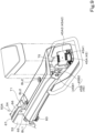
- Figs. 1 and 2 illustrate an embodiment of an agricultural machine 1 according to the present invention.
- the agricultural machine 1 is a tractor 1.
- the agricultural machine 1 may be, instead of a tractor, another agricultural machine (agricultural vehicle) such as a combine or a rice transplanter.
- the direction of arrow A1 in Figs. 1 and 2 will be referred to as the forward direction
- the direction of arrow A2 will be referred to as the backward direction
- the direction of arrow B1 will be referred to as the leftward direction
- the direction of arrow B2 will be referred to as the rightward direction
- the direction of arrow D will be referred to as the vehicle-body width direction (or the width direction).
- a vehicle-body width direction away from a center in the vehicle-body width direction (the direction of arrow D1) will be referred to as the vehicle-body-width outward direction (or the outward direction), and a vehicle-body width direction toward a center in the vehicle-body width direction (the direction of arrow D2) will be referred to as the vehicle-body-width inward direction (or the inward direction).
- the tractor 1 includes a vehicle body 3, a prime mover 4, and a transmission 5.
- a travel device 7 is provided in the vehicle body 3.
- the travel device 7 supports the vehicle body 3 so that the vehicle body 3 is capable of traveling, and has front wheels 7F and rear wheels 7R.
- the front wheels 7F and the rear wheels 7R which are tires in the present embodiment, may be crawlers.
- the prime mover 4 is an engine (diesel engine, gasoline engine), an electric motor, or the like.
- the transmission 5 can switch the propelling force of the travel device 7 by speed change, and can switch between forward movement and backward movement of the travel device 7.
- An operator's seat 10 is provided in the vehicle body 3.
- the operator's seat 10 is protected by a protector 9.
- the protector 9 is a cabin that protects the operator's seat 10 by surrounding the front, the back, the top, and the sides of the operator's seat 10.
- the protector 9 may be a ROPS or the like that protects the operator's seat 10 by covering at least the top of the operator's seat 10.
- Fenders 13 are attached to a lower part the protector 9, and the fenders 13 cover upper parts of the rear wheels 7R.
- a coupler (not shown), which includes a three-point linkage and the like, is provided in a back part of the vehicle body 3.
- a working device (implement or the like) can be removably coupled to the coupler. By coupling the working device to the coupler, the working device can be pulled by the vehicle body 3.
- the working device is a cultivator that performs cultivation, a fertilizer spreader that spreads fertilizer, an agricultural chemical spreader that spreads agricultural chemicals, a harvester that performs harvesting, a mower that performs mowing of grass and the like, a tedder that spreads grass and the like, a rake that gathers grass and the like, a baler that forms grass and the like into a bale, or the like.
- the vehicle body 3 has a vehicle body frame 20.
- the vehicle body frame 20 includes a vehicle body frame 20L provided on the left side and a vehicle body frame 20R provided on the right side.
- the vehicle body frame 20L and the vehicle body frame 20R each extend forward from the transmission 5 and support a lower part of the prime mover 4.
- the vehicle body frame 20L and the vehicle body frame 20R are separated from each other in the vehicle-body width direction.
- a front end part of the vehicle body frame 20L and a front end part of the vehicle body frame 20R are coupled to each other via a front coupling plate 20F.
- a middle part of the vehicle body frame 20L and a middle part of the vehicle body frame 20R are coupled to each other via a middle coupling plate 20M.
- the vehicle body frame 20L and the vehicle body frame 20R support a front axle case 29.
- a front axle 15 (see Fig. 6 ), which rotatably supports the front wheels 7F, is accommodated in the front axle case 29. That is, in the present embodiment, the vehicle body frame 20 is a front axle frame that supports the front axle 15.
- the vehicle body frame 20 may be a frame that supports a structure other than the front axle case 29 (a frame other than the front axle frame).
- a hood 25 is provided upward of the vehicle body frame 20.
- the hood 25 extends in the front-back direction along the vehicle body frame 20.
- the hood 25 is disposed forward of a middle part of the protector 9 in the width direction.
- the hood 25 has a left side wall 25L provided on the left side, a right side wall 25R provided on the right side, and an upper wall portion 25U that couples upper parts of the left side wall 25L and the right side wall 25R.
- An engine room is formed by the left side wall 25L, the right side wall 25R, and the upper wall portion 25U; and the prime mover 4, a cooling fan, a radiator, a battery, and the like are accommodated in the engine room.
- the front wheels 7F are respectively disposed leftward of the left side wall 25L and rightward of the right side wall 25R.
- a weight 26 is provided forward of the hood 25, that is, forward of the vehicle body frames 20L and 20R.
- the weight 26 is attached to a weight bracket (weight attachment portion) 27 provided in a front part of the vehicle body 3.
- the weight bracket 27 is attached to the front coupling plate 20F of the vehicle body frame 20L by using a fastener such as a bolt.
- the periphery of the weight 26 is covered by a weight cover 100.
- the tractor 1 includes a steering device 11.
- the steering device 11 has a steering wheel 11a, a rotary shaft (steering shaft) 11b that rotates as the steering wheel 11a rotates, and an assist mechanism (power steering mechanism) 11c that assists in steering of the steering wheel 11a.
- the assist mechanism 11c includes a hydraulic pump 21, a control valve 22 to which a hydraulic fluid delivered from the hydraulic pump 21 is supplied, and a steering cylinder 23 that is activated by the control valve 22.
- the control valve 22 is a solenoid valve that is activated based on a control signal.
- the control valve 22 is, for example, a three-position switching valve that is switchable by movement of a spool or the like.
- the control valve 22 is switchable also by steering of the steering shaft 11b.
- the steering cylinder 23 is connected to arms (knuckle arms) 24 that change the orientation of the front wheels 7F.
- the steering wheel 11a when the steering wheel 11a is operated, the switching position and the opening of the control valve 22 are switched in accordance with the steering wheel 11a, the steering cylinder 23 extends leftward or rightward in accordance with the switching position and the opening of the control valve 22, and thus the steering direction of the front wheels 7F can be changed.
- the steering device 11 described above is an example, and the configuration of the steering device 11 is not limited to the configuration described above.
- the tractor 1 includes a position detector 30.
- the position detector 30 is attached to a front part of the top panel of the protector 9 via a mounter 31.
- the attachment position of the position detector 30 is not limited to the position illustrated in the figures, and the position detector 30 may be attached onto the top panel of the protector 9 or may be attached to another part of the vehicle body 3.
- the position detector 30 may be attached to the aforementioned working device, such as a cultivator.
- the position detector 30 is a device that detects the position thereof (measured position including latitude and longitude) by using a satellite positioning system. That is, the position detector 30 receives signals (positions of positioning satellites, transmission time, correction information, and the like) transmitted from the positioning satellites, and detects the position (latitude, longitude) based on the received signals. The position detector 30 may detect, as the position (latitude, longitude) thereof, a corrected position that is corrected based on a correction signal and the like from a base station (reference station) that can receive signals from the positioning satellites.
- a base station reference station
- the position detector 30 may have an inertial measurement unit such as a gyroscope sensor or an acceleration sensor, and may detect, as the position thereof, a position corrected by the inertial measurement unit. With the position detector 30, it is possible to detect the position (travel position) of the vehicle body 3 of the tractor 1.
- an inertial measurement unit such as a gyroscope sensor or an acceleration sensor
- the tractor 1 includes a controller 40 and a display 80.
- the controller 40 includes a CPU, an electric circuit, an electronic circuit, and the like, and controls the tractor 1 in various ways.
- the display 80 has a liquid crystal panel, an organic EL panel, or the like, and displays information about various types.
- a state detector 41 which detects a driving state and the like of the tractor 1, and an ignition switch 42 are connected to the controller 40.
- the state detector 41 is, for example, a device that detects a state of a travel system or the like, and detects, for example, states of a crank sensor, a cam sensor, an engine rotation sensor, an accelerator sensor, a vehicle speed sensor, a steering angle sensor, the position detector 30, and the like.
- the state detector 41 may be a device that detects a state of a portion other than the travel system, such as elevation lever detection sensor, a PTO rotation detection sensor, or the like.
- the ignition switch 42 is a switch that is set around the operator's seat 10 and that an operator can operate.
- the ignition switch 42 is a switch that is switchable between ON and OFF. When the ignition switch 42 is ON, the prime mover 4 is driven, and, when the ignition switch 42 is OFF, the prime mover 4 is stopped being driven.
- the ignition switch 42 may include an accessory switch for supplying electric power to electric components. In this case, the ignition switch 42 is switchable between a first ON-position for driving the prime mover 4, a second ON-position for supplying electric power to electric components, and an OFF-position.
- a seat-occupation detector 43 is connected to the controller 40.
- the seat-occupation detector 43 is a device for detecting whether or not the operator's seat 10 is occupied.
- the seat-occupation detector 43 is a pressure sensor or a vibration sensor that is set in a seat portion or a backrest of the operator's seat 10, a camera that is set around the operator's seat 10, or the like.
- the seat-occupation detector 43 detects that the operator's seat 10 is occupied if a pressure (vibration) of a predetermined magnitude or more is detected, and the seat-occupation detector 43 detects that the operator's seat 10 is not occupied if a pressure (vibration) of less than a predetermined magnitude is detected.
- the seat-occupation detector 43 When the seat-occupation detector 43 is a camera, the seat-occupation detector 43 detects that the operator's seat is occupied if the camera detects a person on the operator's seat 10, and the seat-occupation detector 43 detects that the operator's seat 10 is not occupied if the camera does not detect a person on the operator's seat 10.
- the seat-occupation detector 43 is an example and is not limited.
- the controller 40 performs control of the travel system of the tractor 1 and control of the working system of the tractor 1.
- the controller 40 controls, for example, the engine rotation speed, the vehicle speed, the steering angle of the steering device 11, and the like based on a detection state detected by the state detector 41.
- the controller 40 performs control of autonomous travel based on a detection state detected by the state detector 41.
- the controller 40 includes an autonomous travel controller 40A.
- the autonomous travel controller 40A includes an electric/electronic circuit provided in the controller 40, a program stored in the controller 40, and the like.
- a travel route (planned travel route) L1 is created by using the display 80 and the like. First, creation of the planned travel route L1 will be described.
- the display 80 displays a creation screen M1 for creating the planned travel route L1.
- a creation screen M1 for creating the planned travel route L1.
- the display 80 displays on the creation screen M1 an agricultural field map (agricultural field map MP2) input to the agricultural-field input portion 86.
- the planned travel route L1 for example, in the agricultural field map MP2, it is possible to create straight movement portions L1a representing straight movements and turning portions L1b representing turns, as the planned travel route L1.
- the distances between the straight movement portions L1a in the width direction, the number of the straight movement portions L1a, and the like may be set in any appropriate manner. That is, with the display 80, it is possible to set (create) the planned travel route L1 for performing autonomous travel in the agricultural field H1.
- a planned travel route L1 created by using an external apparatus such as a server may be acquired by the tractor 1 and displayed on the display 80.
- a command to start autonomous travel may be issued by using a remote control 81 for performing remote control, or by using a switch 82 that is set around the operator's seat or the like of the tractor 1.
- the autonomous travel controller 40A sets the switching position and the opening of the control valve 22 so that at least the travel position (position detected by the position detector 30) of the vehicle body 3 coincides with a predetermined travel route (travel path), that is, so that the vehicle body 3 coincides with the planned travel route L1.
- the controller 40 sets the movement direction and the movement distance of the steering cylinder 23 (the steering direction and the steering angle of the front wheels 7F) so that the travel position of the tractor 1 coincides with the planned travel route L1.
- the autonomous travel controller 40A compares the travel position of the vehicle body 3 with a position indicated by the planned travel route L1 (planned travel position). When the travel position coincides with the planned travel position, the autonomous travel controller 40A does not change and holds the steering angle and steering direction of the steering wheel 11a of the steering device 11 (the steering angle and the steering direction of the front wheels 7F) (does not change and maintains the opening and the switching position of the control valve 22). When the travel position does not coincide with the planned travel position, the autonomous travel controller 40A changes the steering angle and/or the steering direction of the steering wheel 11a of the steering device 11 (changes the opening and/or the switching position of the control valve 22) so that the difference (displacement) between the travel position and the planned travel position becomes zero.
- the autonomous travel controller 40A changes the steering angle of the steering device 11 based on the difference between the travel position and the planned travel position. If the orientation of the planned travel route L1 differs from the orientation (vehicle-body orientation) of the movement direction (travel direction) of the tractor 1 (the vehicle body 3), the autonomous travel controller 40A may set the steering angle so that the vehicle-body orientation coincides with the orientation of the planned travel route L1. In autonomous travel control, the autonomous travel controller 40A may set the final steering angle in autonomous travel control based on a steering angle obtained based on the difference (positional deviation) and a steering angle obtained based on an orientational deviation. The steering angle may be set by using a method different from the aforementioned method of setting the steering angle in autonomous travel control.
- the autonomous travel controller 40A may control the rotation speed of the travel device 7, that is, the front wheels 7F and/or the rear wheels 7R so that the actual vehicle speed of the tractor 1 (the vehicle body 3) coincides with a vehicle speed corresponding to a predetermined planned travel route L1.
- the autonomous travel controller 40A controls autonomous travel based on the detection result of detecting an obstacle by an obstacle detector 45. For example, the autonomous travel controller 40A continues autonomous travel when the obstacle detector 45 is not detecting an obstacle, and stops autonomous travel when the obstacle detector 45 detects an obstacle. To be more specific, when the obstacle detector 45 detects an obstacle, the autonomous travel controller 40A stops autonomous travel by stopping travel of the tractor 1 if the distance between the obstacle and the tractor 1 is less than or equal to a predetermined threshold (stop threshold).
- stop threshold a predetermined threshold
- the autonomous travel controller 40A continues autonomous travel when the seat-occupation detector 43 is detecting that the operator's seat is occupied and stops autonomous travel when the seat-occupation detector 43 detects that the operator's seat is not occupied.
- a figure G1 representing the tractor 1 (the vehicle body 3) and the planned travel route L1 are displayed on the display 80.
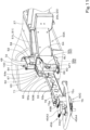
- the tractor 1 includes a plurality of obstacle detectors 45.
- Each of the plurality of obstacle detectors 45 can detect an object, that is, an obstacle that is present around the tractor 1.
- At least one of the plurality of obstacle detectors 45 is provided forward of the protector 9 and outward of the hood 25. That is, at least one obstacle detector 45 is disposed, in a region forward of the protector 9 of the tractor 1, in a region further leftward than the left side wall 25L of the hood 25 or a region further rightward than the right side wall 25R of the hood 25.
- the obstacle detectors 45 are provided forward of the front wheels 7F and further outward than the front wheels 7F.
- the obstacle detector 45L is provided forward of the left front wheel 7F and further outward (leftward) than the left front wheel 7.
- the obstacle detector 45R is provided forward of the right front wheel 7F and further outward (rightward) than the right front wheel 7F. In other words, the obstacle detector 45L is provided leftward and forward of the left front wheel 7F, and the obstacle detector 45R is provided rightward and forward of the right front wheel 7F.
- the obstacle detector 45 is a laser scanner 45A, a sonar 45B, and the like.
- the laser scanner 45A detects an object (obstacle) by emitting laser light as a detection wave.
- the laser scanner 45A detects the distance to an obstacle based on the time from emission to receipt of laser light.
- the laser scanner 45A includes a light emitter/receiver 45A1 and a housing 45A2.
- the light emitter/receiver 45A1 emits laser light and receives the emitted laser light reflected by an obstacle (reflected light).
- the light emitter/receiver 45A1 includes an emission portion that emits laser light (detection wave) and a receiving portion that receives the laser light (detection wave) reflected by an obstacle.
- the housing 45A2 is a case that accommodates and holds the light emitter/receiver 45A1.
- the housing 45A2 includes an upper body 45A3 disposed upward of the light emitter/receiver 45A1 and a lower body 45A4 disposed downward of the light emitter/receiver 45A1. All or part of the space between the upper body 45A3 and the lower body 45A4, that is, the periphery of the light emitter/receiver 45A1 is open, and laser light (detection wave) can pass therethrough.
- the sonar 45B detects an object (obstacle) by emitting a sound wave as a detection wave.
- the sonar 45B includes a sound emitter/receiver 45B 1 and a housing 45B2.
- the sound emitter/receiver 45B1 emits a sound wave and receives the emitted sound wave reflected by an obstacle. That is, the sound emitter/receiver 45B1 includes an emission portion that emits a sound wave (detection wave) and a receiving portion that receives the sound wave (detection wave) reflected by an obstacle.
- the housing 45B2 is a case that accommodates and holds the sound emitter/receiver 45B1.
- the sonar 45B detects the distance to an obstacle based on the time from emission to receipt of a sound wave.
- the laser scanner 45A and the sonar 45B are disposed forward of the front wheel 7F and outward of the front wheel 7F.
- at least the receiving portions (the light emitter/receiver 45A1 and the sound emitter/receiver 45B 1) of the laser scanner 45A and the sonar 45B are disposed forward of the front wheel 7F and outward of the front wheel 7F.
- the laser scanner 45A and the sonar 45B are set at positions that are further downward than the upper wall portion 25U of the hood 25 and lower than an upper end part of the front wheel 7F. Therefore, the light emitter/receiver 45A1 of the laser scanner 45A and the sound emitter/receiver 45B1 of the sonar 45B are also set at positions that are further downward than the upper wall portion 25U of the hood 25 and are lower than the upper end part of the front wheel 7F.
- the laser scanner 45A (the light emitter/receiver 45A1) and the sonar 45B (the sound emitter/receiver 45B1) are positioned further downward than the upper end part the front wheel 7F and further upward than the front axle 15.
- the laser scanner 45A is disposed further outward than the sonar 45B.
- the laser scanner 45A (the light emitter/receiver 45A1) is disposed further outward than an imaginary line X1 that is positioned outward by the width of the front wheel 7F (tread width) from an outer end of the front wheel 7F in the width direction.
- the sonar 45B is disposed further inward than the imaginary line X1.
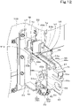
- the obstacle detector 45 is supported by the vehicle body 3 via a support 50.
- the support 50 can change the position of the obstacle detector 45 to a detection position (see Figs. 4 and 15 ) and to a retracted position (see Figs. 5 and 16 ).
- the support 50 includes a support 50L that supports the obstacle detector 45 leftward of the vehicle body 3 and a support 50R that supports the obstacle detector 45 rightward of the vehicle body 3.
- the support 50L and the support 50R have the same configuration except that they are symmetric to each other about a center line CL1 in the vehicle-body width direction.
- the support 50 extends outward from the vehicle body frame (front axle frame) 20. To be specific, the support 50L extends leftward from the vehicle body frame 20L. The support 50R extends rightward from the vehicle body frame 20R.
- the support 50 has a first support portion 50A, a second support portion 50B, and a third support portion 50C.
- the first support portion 50A has an attachment arm 51, an attachment plate 52, a front support plate 53, and a back support plate 54.
- the attachment arm 51 extends forward and outward from a front side part of the vehicle body frame 20.
- the attachment arm 51 includes an attachment arm 51L and an attachment arm 51R.
- the attachment arm 51L is attached to a front part of a left side surface of the vehicle body frame 20L, and extends leftward and forward from the front part.
- the attachment arm 51R is attached to a front part of a right side surface of the vehicle body frame 20R, and extends rightward and forward from the front part.
- the attachment plate 52 is attached to a front end part of each of the attachment arms 51L and 51R, and one surface thereof faces outward and the other surface thereof faces inward.
- the attachment plate 52 on the left side, which is attached to the attachment arm 51L, and the attachment plate 52 on the right side, which is attached to the attachment arm 51R, are coupled via a coupling 49.
- the coupling 49 is formed from a pipe, extends through a space above the weight cover 100, and couples an upper part of the attachment plate 52 on the left side and an upper part of the attachment plate 52 on the right side.
- the front support plate 53 and the back support plate 54 have the same shape, and are disposed parallel to each other and so as to face each other with a distance therebetween in the front-back direction.
- the front support plate 53 and the back support plate 54 are attached to one surface of the attachment plate 52 and extend outward.
- a lower support plate 56 is in contact with a lower edge of the front support plate 53 and a lower edge of the back support plate 54.
- An upper support plate 57 is in contact with an upper edge of the front support plate 53 and an upper edge of the back support plate 54.
- the lower support plate 56 and the upper support plate 57 are fixed to the attachment plate 52.
- the front support plate 53 is shown by an imaginary line.
- a first front hole 53a and a second front hole 53b are formed in the front support plate 53.
- a first back hole 54a and a second back hole 54b are formed the back support plate 54.
- the first back hole 54a is at a position facing the first front hole 53a
- the second back hole 54b is at a position facing the second front hole 53b.
- a tubular body 58 and a receiver 59 are fixed to an upper part of the back support plate 54.
- the tubular body 58 has a central hole whose axial direction extends in the front-back direction.
- the axis of the central hole of the tubular body 58 and the center of the second back hole 54b are disposed on the same straight line.
- the receiver 59 is fixed to a lower part of the front support plate 53 and a lower part of the back support plate 54.
- the receiver 59 is a U-shaped member, and has a front portion 59a fixed to a front surface of the front support plate 53, a back portion 59b fixed to a back surface of the back support plate 54, and a lower portion 59c connecting the front portion 59a and the back portion 59b.
- a knob bolt 60 is screwed into the lower portion 59c of the receiver 59.
- the axis of the threaded shaft of the knob bolt 60 is oriented in the up-down direction.
- a distal end member 61 is attached to the threaded shaft of the knob bolt 60. The position (height) of the distal end member 61 can be adjusted by rotating the knob bolt 60.
- the second support portion 50B is supported between the front support plate 53 and the back support plate 54.
- the second support portion 50B has a one-side plate 65, an other-side plate 66, a coupling plate 67, and a support arm 55.
- the one-side plate 65 and the other-side plate 66 have the same shape, and are disposed parallel to each other and so as to face each other with a distance therebetween in the front-back direction.
- the one-side plate 65 faces the front support plate 53, and the other-side plate 66 faces the back support plate 54.
- a first one-side hole 65a, a second one-side hole 65b, and a third one-side hole 65c are formed in the one-side plate 65.
- a first other-side hole 66a, a second other-side hole 66b, and a third other-side hole 66c are formed in the other-side plate 66.
- the first other-side hole 66a is at a position facing the first one-side hole 65a.
- the second other-side hole 66b is at a position facing the second one-side hole 65b.
- the third other-side hole 66c is at a position facing the third one-side hole 65c.
- the front support plate 53 and the one-side plate 65 are omitted.
- the coupling plate 67 is a strip-shaped plate bent into an L-shape, and couples the one-side plate 65 and the other-side plate 66.
- a cylindrical boss 68 is fitted into the first one-side hole 65a and the first other-side hole 66a.
- a front end portion of the boss 68 is fitted into the first one-side hole 65a, and the back end portion of the boss 68 is fitted into the first other-side hole 66a.
- a central hole 68a of the boss 68, the first front hole 53a, and the first back hole 54a are disposed on the same straight line, and a threaded shaft of a bolt BL1 (see Figs. 13 and 11 ) is inserted so as to extend through these holes.
- a nut NT1 is screwed onto the threaded shaft of the bolt BL1.
- the second support portion 50B (the one-side plate 65, the other-side plate 66, the coupling plate 67) is interposed and supported between the front support plate 53 and the back support plate 54.
- the second support portion 50B is rotatable relative to the first support portion 50A with the threaded shaft of the bolt BL1 as a supporting point.
- the threaded shaft of the bolt BL1 functions as a support shaft that rotatably supports the second support portion 50B.
- a first contact member 69 and a second contact member 70 are fixed between the one-side plate 65 and the other-side plate 66.
- the first contact member 69 and the second contact member 70 are disposed on the same circle that is centered on a support shaft (the threaded shaft of the bolt BL1). That is, the first contact member 69 and the second contact member 70 are equidistant from the support shaft (the threaded shaft of the bolt BL1).
- the first contact member 69 and the second contact member 70 are disposed at positions that are separated by 90° around the support shaft (the threaded shaft of the bolt BL1).
- the support arm 55 extends from the first support portion 50A outward of the vehicle body.
- One end portion of the support arm 55 and an abutting member 71 described below are connected to the coupling plate 67.
- the third support portion 50C is connected to the other end portion of the support arm 55.
- the third support portion 50C supports the obstacle detector 45.
- the third support portion 50C has a support bracket 75 and a support stay 76.
- the support bracket 75 supports the laser scanner 45A.
- the support bracket 75 is a substantially C-shaped member including an upper horizontal portion 75a, a lower horizontal portion 75b, and a vertical portion 75c.
- the vertical portion 75c is fixed to the other end portion of the support arm 55.
- the upper horizontal portion 75a supports the upper body 45A3 of the housing 45A2.
- the lower horizontal portion 75b supports the lower body 45A4 of the housing 45A2.
- the support stay 76 is fixed to a middle part of the support arm 55 and supports the sonar 45B.
- the sonar 45B is attached to the support stay 76 so that the sound emitter/receiver 45B1 faces forward and inward of the vehicle body.
- the attachment plate 52, the front support plate 53, the back support plate 54 (see Figs. 10 to 12 and other figures), and the like of the first support portion 50A described above are included in a position changing mechanism 63 that changes the position of the obstacle detector 45.
- the position changing mechanism 63 is a mechanism that changes the position of the obstacle detector 45 to a detection position that is a predetermined position for detecting an obstacle and to a retracted position that is retracted from the detection position toward the vehicle body 3.
- the position changing mechanism 63, together with the second support portion 50B and the third support portion 50C of the support 50, can change the position of the obstacle detector 45.
- Figs. 4 and 15 illustrate a state in which the obstacle detector 45 is in the detection position.
- Figs. 5 and 16 illustrate a state in which the obstacle detector 45 is in the retracted position.
- the change in the position of the obstacle detector 45 between the detection position and retracted position can be performed by rotating the second support portion 50B relative to the first support portion 50A with the threaded shaft of the bolt BL1 (support shaft) as a supporting point.
- the support arm 55 when the obstacle detector 45 is in the detection position, the support arm 55 extends in a horizontal direction.
- the support arm 55 of the support 50L which supports the obstacle detector 45 leftward of the vehicle body 3, extends horizontally leftward.
- the support arm 55 of the support 50R, which supports the obstacle detector 45 rightward of the vehicle body 3, extends horizontally rightward.
- the emission direction of laser light emitted from the light emitter/receiver 45A1 is the horizontal direction.
- the second front hole 53b, the second one-side hole 65b, the second other-side hole 66b, and the second back hole 54b are disposed on the same straight line, and a pin 64 is inserted so as to extend through these holes and the tubular body 58.
- the second support portion 50B (the one-side plate 65, the other-side plate 66, the coupling plate 67, the support arm 55) becomes non-rotatable relative to the front support plate 53 and the back support plate 54, and the position of the second support portion 50B is fixed.
- the support arm 55 is positioned relative to the vehicle body 3 in a state of extending in a horizontal direction (detection posture), and the obstacle detector 45 is held in the detection position.
- the distal end member 61 which is attached to the threaded shaft of the knob bolt 60, is in contact with the first contact member 69.
- the pin 64 is pulled out from the holes.
- the pin 64 can be pulled out by gripping a grip portion 64a provided at an end portion of the pin 64.
- the second support portion 50B (the one-side plate 65, the other-side plate 66, the coupling plate 67, the support arm 55) becomes rotatable relative to the front support plate 53 and the back support plate 54.
- the distal end member 61 is in contact with the first contact member 69, the second support portion 50B cannot rotate downward and can rotate only upward.
- the second support portion 50B (the one-side plate 65, the other-side plate 66, the coupling plate 67, the support arm 55) rotates upward with the support shaft (the threaded shaft of the bolt BL1) as a supporting point (see arrow U1 in Fig. 15 ).
- the upward rotational range of the support arm 55 is defined by the abutting member 71 and a protruding shaft 72 (see Figs. 12 and 14 ).
- the abutting member 71 is fixed to an upper part of the support arm 55.
- the protruding shaft 72 protrudes outward from a shaft supporter 73 disposed on an upper part of the upper support plate 57.
- the support arm 55 can be rotated upward until the abutting member 71 comes into contact with the protruding shaft 72.
- the support arm 55 is in a state of extending upward (retracted position).
- the second front hole 53b, the second back hole 54b, the third one-side hole 65c, and the third other-side hole 66c are disposed on the same straight line.
- the second support portion 50B (the one-side plate 65, the other-side plate 66, the coupling plate 67, the support arm 55) becomes non-rotatable relative to the front support plate 53 and the back support plate 54, and the position of the second support portion 50B is fixed.
- the support arm 55 is positioned relative to the vehicle body 3 in a state of extending upward, and the obstacle detector 45 is held in the retracted position.
- the distal end member 61 which is attached to the threaded shaft of the knob bolt 60, is in contact with the second contact member 70.
- the position changing mechanism 63 it is possible to change the position of the obstacle detector 45 to the detection position and to the retracted position.
- the obstacle detector 45 can detect an obstacle around the vehicle body 3.
- the obstacle detector 45 is moved from the detection position to the retracted position.
- the position changing mechanism 63 has a posture detector for detecting whether the support arm 55 is in the detection position or in the retracted position.
- a posture detector for example, a detector that detects the retracted position when the abutting member 71 in contact with the protruding shaft 72 and detects the detection position when the abutting member 71 is separated from the protruding shaft 72 is used.
- the detection information of the posture detector is input to the controller 40.
- the autonomous travel controller 40A stops the vehicle body 3 based on detection information about the obstacle detected by the obstacle detector.
- the autonomous travel controller 40A stops the vehicle body 3 based on detection information about the obstacle detected by the obstacle detector.
- the vehicle body 3 In the effective mode, when autonomous travel is being performed, if the obstacle detector 45 detects an obstacle and the detected detection information indicates that the distance between the obstacle and the vehicle body 3 is less than or equal to a predetermined distance, the vehicle body 3 is stopped. On the other hand, in the ineffective mode, when autonomous travel is being performed, even if the obstacle detector 45 detects an obstacle and the detected detection information indicates that the distance between the obstacle and the vehicle body 3 is less than or equal to a predetermined distance, the vehicle body 3 is not stopped and autonomous travel is continued.
- the ineffective mode when autonomous travel is being performed, even if the obstacle detector 45 detects an obstacle, the detection of the obstacle (detection information) is not output to the autonomous travel controller 40A, and thus stopping of the vehicle body 3 by the autonomous travel controller 40A is not performed. Further alternatively, in the ineffective mode, when autonomous travel is being performed, the obstacle detector 45 stops detection of an obstacle, and thus stopping of the vehicle body 3 is not performed. That is, in the ineffective mode, in autonomous travel in the agricultural field H1, stopping of the vehicle body 3 based on detection information of the obstacle detector 45 is not performed irrespective of whether or not an obstacle is detected.
- the controller 40 includes a mode switcher 40B.
- the mode switcher 40B includes an electric/electronic circuit provided in the controller 40, a program stored in the controller 40, and the like. As illustrated in Fig. 18 , when an operator performs a predetermined operation on the display 80, the mode switcher 40B displays a setting screen M2.
- the setting screen M2 displays a first selecting portion 101 for selecting the effective mode and a second selecting portion 102 for selecting the ineffective mode. Selection between the first selecting portion 101 and the second selecting portion 102 can be performed by using an operation member provided in the display 80 or an operation member provided around the operator's seat 10.
- the mode switcher 40B switches to the effective mode when the first selecting portion 101 is selected, and switches to the ineffective mode when the second selecting portion 102 is selected.
- the mode switcher 40B sets the effective mode as a default.
- the display 80 displays on the setting screen M2 a state in which the first selecting portion 101 is selected. That is, in a state in which driving of the prime mover 4 is stopped or in a state in which the prime mover 4 is restarted after stopped being driven, the mode switcher 40B sets the effective mode as a default.
- the mode switcher 40B switches from the ineffective mode to the effective mode. That is, in a state in which the ignition switch 42 is switched from ON to OFF in a state in which the ineffective mode is maintained, the mode switcher 40B switches to the effective mode.
- the mode switcher 40B performs switching between the effective mode and the ineffective mode in accordance with an operation on the setting screen M2 displayed on the display 80.
- switching between the modes may be restrained.
- the controller 40 includes a switching restrainer 40C.
- the switching restrainer 40C includes an electric/electronic circuit provided in the controller 40, a program stored in the controller 40, and the like.
- the switching restrainer 40C allows the mode switcher 40B to switch from the effective mode to the ineffective mode.
- the switching restrainer 40C allows (permits) the mode switcher 40B to switch from the effective mode to the ineffective mode due to selection of the second selecting portion 102.
- the switching restrainer 40C does not allow (permit) the mode switcher 40B to switch from the effective mode to the ineffective mode due to selection of the second selecting portion 102. That is, when the obstacle detector 45 is in the retracted position, the switching restrainer 40C does not permit the mode switcher 40B to accept selection of the second selecting portion 102.
- the switching restrainer 40C does not allow switching from the effective mode to the ineffective mode. Instead, restraint of the ineffective mode may be performed based on whether or not the operator's seat is occupied by an operator.
- the controller 40 includes a switching restrainer 40D.
- the switching restrainer 40D includes an electric/electronic circuit provided in the controller 40, a program stored in the controller 40, and the like.
- the switching restrainer 40D allows the mode switcher 40B to switch from the effective mode to the ineffective mode. For example, in a state in which the setting screen M2 is displayed on the display 80, when the operator's seat is occupied by an operator, the switching restrainer 40D allows (permits) the mode switcher 40B to switch from the effective mode to the ineffective mode due to selection of the second selecting portion 102.
- the switching restrainer 40D does not allow the mode switcher 40B to switch from the effective mode to the ineffective mode due to selection of the second selecting portion 102. That is, when the operator's seat 10 is not occupied by an operator, the switching restrainer 40D does not allow the mode switcher 40B to accept selection of the second selecting portion 102.
- Fig. 19A illustrates an operation flow of autonomous travel.
- Fig. 19A it is assumed that autonomous travel is not performed immediately after the ignition switch 42 is turned ON.
- Fig. 19A is an operation flow of autonomous travel in the ineffective mode.
- the mode switcher 40B determines whether or not the ignition switch 42 is ON (S 1). For example, if the ignition switch 42 is ON (if the prime mover 4 is being driven or electric power is being supplied to electric components) (S 1, Yes), the mode switcher 40B sets to the effective mode (S2). When a predetermined operation is performed, the display 80 displays the setting screen M2 (S3).
- the switching restrainer 40C determines whether or not the obstacle detector 45 is in the retracted position (S4). If the obstacle detector 45 is in the retracted position (S4, Yes), the switching restrainer 40C allows the mode switcher 40B to switch from the effective mode to the ineffective mode on the setting screen M2, and accepts the ineffective mode (S5).
- the switching restrainer 40C does not allow the mode switcher 40B to switch from the effective mode to the ineffective mode on the setting screen M2, and does not accept the ineffective mode (S6).
- the autonomous travel controller 40A outputs an anomaly (alarm) to the display 80, and the display 80 displays on the setting screen M2 or the like an anomaly (alarm) indicating that the obstacle detector 45 is not in the retracted position (S7).
- the autonomous travel controller 40A After accepting the ineffective mode (in and after S5), the autonomous travel controller 40A waits for acquisition of a start command to start autonomous travel. When a start button of the remote control 81, the switch 82, or the like is pressed and the start command is acquired (S8), the autonomous travel controller 40A determines whether or not the operator's seat is occupied by an operator (S9). If the operator's seat 10 is occupied by an operator (S9, Yes), the autonomous travel controller 40A performs autonomous travel control, that is, starts autonomous travel in the ineffective mode (S10).
- the autonomous travel controller 40A When autonomous travel is started in the ineffective mode, the autonomous travel controller 40A does not perform stopping of the vehicle body 3 due to detection of an obstacle, irrespective of the detection information of the obstacle detector 45. As illustrated in Fig. 20 , when autonomous travel is being performed in the ineffective mode, the display 80 displays in a message portion 88 that autonomous travel in the ineffective mode is being performed. The display 80 may display in the message portion 88 that autonomous travel in the effective mode is being performed.
- the autonomous travel controller 40A outputs an anomaly (alarm) to the display 80, and displays on the display 80 an anomaly (alarm) indicating that the operator's seat is not occupied (S11).
- the autonomous travel controller 40A prohibits autonomous travel.
- the autonomous travel controller 40A stops travel of the vehicle body 3 (S12). If the operator's seat is occupied when autonomous travel is being performed after starting autonomous travel (S10 to S9, when the process proceeds to Yes), the autonomous travel controller 40A continues autonomous travel.
- Fig. 19B illustrates an operation flow of autonomous travel different from that of Fig. 19A . Also in Fig. 19B , it is assumed that autonomous travel is not performed immediately after the ignition switch 42 is turned ON. Fig. 19B is an operation flow of autonomous travel in the ineffective mode.
- the mode switcher 40B determines whether or not the ignition switch 42 is ON (S1). For example, if the ignition switch 42 is ON (if the prime mover 4 is being driven or electric power is being supplied to electric components) (S1, Yes), the mode switcher 40B sets to the effective mode (S2). When a predetermined operation is performed, the display 80 displays the setting screen M2 (S3).
- the switching restrainer 40D determines whether or not the operator's seat is occupied by an operator (S20). If the operator's seat is occupied by an operator (S20, Yes), the switching restrainer 40D allows the mode switcher 40B to switch from the effective mode to the ineffective mode on the setting screen M2, and accepts the ineffective mode (S21).
- the switching restrainer 40D does not allow the mode switcher 40B to switch from the effective mode to the ineffective mode on the setting screen M2, and does not accept the ineffective mode (S22).
- the autonomous travel controller 40A outputs an anomaly (alarm) to the display 80, and the display 80 displays on the setting screen M2 or the like an anomaly (alarm) indicating that the operator's seat is not occupied by an operator (S23). Descriptions of S8 to S12 in 19B, which are similar to those of Fig. 19A , will be omitted.
- switching from the effective mode to the ineffective mode is allowed if the obstacle detector 45 is in the retracted position or if the operator's seat is occupied by an operator.
- switching from the effective mode to the ineffective mode may be allowed if the obstacle detector 45 is in the retracted position and the operator's seat is occupied by an operator.
- switching from the effective mode to the ineffective mode is restrained based on the position of the obstacle detector 45 (detection position, retracted position) or the state of the operator's seat (occupied, not occupied).
- switching from the effective mode to the ineffective mode may be performed irrespective of the position of the obstacle detector 45 and the state of the operator's seat.
- whether or not to allow starting of autonomous travel may be set based on the position of the obstacle detector 45.
- the autonomous travel controller 40A can start autonomous travel if the obstacle detector 45 is in the retracted position, and, when in the ineffective mode, the autonomous travel controller 40A does not start autonomous travel if the obstacle detector 45 is not in the retracted position.
- Fig. 19C illustrates an operation flow of autonomous travel different from those of Figs. 19A and 19B . Also in Fig. 19C , it is assumed that autonomous travel is not performed immediately after the ignition switch 42 is turned ON. Fig. 19C is an operation flow of autonomous travel in the ineffective mode.
- the mode switcher 40B determines whether or not the ignition switch 42 is ON (S 1). For example, if the ignition switch 42 is ON (if the prime mover 4 is being driven or electric power is being supplied to electric components) (S 1, Yes), the mode switcher 40B sets to the effective mode (S2). When a predetermined operation is performed, the display 80 displays the setting screen M2 (S3).
- the autonomous travel controller 40A determines whether or not the obstacle detector 45 is in the retracted position (S51). If the obstacle detector 45 is not in the retracted position (S51, No), the autonomous travel controller 40A outputs an anomaly (alarm) to the display 80, and the display 80 displays on the setting screen M2 or the like an anomaly (alarm) indicating that the obstacle detector 45 is not in the retracted position (S52).
- Descriptions of S8 to S12 in 19C which are similar to those of Figs. 19A and 19B , will be omitted.
- the autonomous travel controller 40A when autonomous travel is being performed (during autonomous travel) in the ineffective mode, the autonomous travel controller 40A continues autonomous travel when in the retracted position, and, on the other hand, stops autonomous travel when changed from the retracted position to the detection position.
- the autonomous travel controller 40A determines whether or not the obstacle detector 45 is in the detection position.
- the autonomous travel controller 40A starts autonomous travel if the obstacle detector 45 is in the detection position and starting of autonomous travel is acquired.
- the autonomous travel controller 40A may start autonomous travel if the following three conditions are satisfied: a condition that the obstacle detector 45 is in the detection position, a condition that starting of autonomous travel is acquired, and a condition that the operator's seat is occupied.
- an anomaly (alarm) indicating that the obstacle detector 45 is in the retracted position may be displayed on the display 80.
- the agricultural machine 1 includes: the vehicle body 3 that is capable of traveling; the obstacle detector 45 that is capable of detecting an obstacle; the autonomous travel controller 40A that performs autonomous travel of the vehicle body 3 and that, when performing the autonomous travel, stops the vehicle body 3 based on detection information about an obstacle detected by the obstacle detector 45; and the mode switcher 40B that switches a mode during the autonomous travel in an agricultural field between an effective mode in which the stopping of the vehicle body 3 based on the detection information is allowed and an ineffective mode in which the stopping of the vehicle body based on the detection information is not allowed.
- the agricultural machine 1 includes the mode switcher 40B, during autonomous travel in the agricultural field, when in the effective mode, it is possible to stop the vehicle body 3 based on the detection information detected by the obstacle detector 45.
- the agricultural machine 1 includes the support 50 to which the obstacle detector 45 is attached and that is capable of changing the position of the obstacle detector 45 to the detection position and to the retracted position, and the autonomous travel controller 40A is allowed to perform the autonomous travel when the autonomous travel controller 40A is in the ineffective mode and the obstacle detector 45 is in the retracted position.
- the autonomous travel controller 40A is allowed to perform the autonomous travel when the autonomous travel controller 40A is in the ineffective mode and the obstacle detector 45 is in the retracted position.
- the agricultural machine 1 includes the seat-occupation detector 43 that detects whether or not the operator's seat 10 is occupied, and the autonomous travel controller 40A is allowed to start the autonomous travel when the seat-occupation detector 43 is detecting that the operator's seat 10 is occupied.
- the autonomous travel controller 40A is allowed to start the autonomous travel when the seat-occupation detector 43 is detecting that the operator's seat 10 is occupied.
- the agricultural machine 1 includes: the support 50 to which the obstacle detector 45 is attached and that is capable of changing the position of the obstacle detector 45 to the detection position and to the retracted position; and the switching restrainer 40C that allows the mode switcher 40B to switch from the effective mode to the ineffective mode when the obstacle detector 45 is in the retracted position, and does not allow the mode switcher 40B to switch from the effective mode to the ineffective mode when the obstacle detector 45 is in the detection position.
- the switching restrainer 40C that allows the mode switcher 40B to switch from the effective mode to the ineffective mode when the obstacle detector 45 is in the retracted position, and does not allow the mode switcher 40B to switch from the effective mode to the ineffective mode when the obstacle detector 45 is in the detection position.
- the agricultural machine 1 includes: the seat-occupation detector 43 that detects whether the operator's seat is occupied; and the switching restrainer 40D that allows the mode switcher 40B to switch from the effective mode to the ineffective mode when the seat-occupation detector 43 is detecting that the operator's seat is occupied and does not allow the mode switcher 40B to switch from the effective mode to the ineffective mode when the seat-occupation detector 43 detects that the operator's seat is not occupied.
- the seat-occupation detector 43 that detects whether the operator's seat is occupied
- the switching restrainer 40D that allows the mode switcher 40B to switch from the effective mode to the ineffective mode when the seat-occupation detector 43 is detecting that the operator's seat is occupied and does not allow the mode switcher 40B to switch from the effective mode to the ineffective mode when the seat-occupation detector 43 detects that the operator's seat is not occupied.
- the agricultural machine 1 includes the seat-occupation detector 43 that detects whether the operator's seat is occupied, and the autonomous travel controller 40A, when performing the autonomous travel, continues performing the autonomous travel when the seat-occupation detector 43 is detecting that the operator's seat is occupied, and stops the autonomous travel when the seat-occupation detector 43 detects that the operator's seat is not occupied.
- the autonomous travel controller 40A when performing the autonomous travel, continues performing the autonomous travel when the seat-occupation detector 43 is detecting that the operator's seat is occupied, and stops the autonomous travel when the seat-occupation detector 43 detects that the operator's seat is not occupied.
- the agricultural machine 1 includes the support 50 to which the obstacle detector 45 is attached and that is capable of changing the position of the obstacle detector 45 to the detection position and to the retracted position, and the autonomous travel controller 40A, when performing the autonomous travel and in the ineffective mode, continues performing the autonomous travel when the obstacle detector 45 is in the retracted position, and stops the autonomous travel when the position of the obstacle detector 45 changes from the retracted position to the detection position.
- the autonomous travel controller 40A when performing the autonomous travel and in the ineffective mode, continues performing the autonomous travel when the obstacle detector 45 is in the retracted position, and stops the autonomous travel when the position of the obstacle detector 45 changes from the retracted position to the detection position.
- the agricultural machine 1 includes the prime mover 4 and the ignition switch 42 that performs switching between ON and OFF of driving of the prime mover 4, and the mode switcher 40B sets the effective mode as a default according to switching of the ignition switch 42 from OFF to ON, and, when the ineffective mode is set, switches the ineffective mode to the effective mode according to switching of the ignition switch 42 from ON to OFF.
- the mode switcher 40B sets the effective mode as a default according to switching of the ignition switch 42 from OFF to ON, and, when the ineffective mode is set, switches the ineffective mode to the effective mode according to switching of the ignition switch 42 from ON to OFF.
- the agricultural machine 1 includes the display 80 that displays whether the autonomous travel controller is in the effective mode or in the ineffective mode. Thus, it is possible to allow an operator to reliably grasp whether autonomous travel is performed in the effective mode or autonomous travel is performed in the ineffective mode.
- the autonomous travel controller 40A stops the vehicle body 3 if the autonomous travel controller 40A, when in the effective mode, acquires detection of an obstacle by the obstacle detector 45 as the detection information. Thus, it is possible to reliably stop the vehicle body 3 when an obstacle is detected during autonomous travel in the effective mode.
- the obstacle detector 45 even when detecting the obstacle, does not output detection of the obstacle to the autonomous travel controller 40A when in the ineffective mode.
- the obstacle detector 45 even when detecting the obstacle, does not output detection of the obstacle to the autonomous travel controller 40A when in the ineffective mode.
- the obstacle detector 45 may output the detection information to the controller 40 other than the autonomous travel controller 40A to store the detection information in the controller 40.
- the detection information may be grasp what kind of an object is detected as the obstacle by analyzing the detection information.
Landscapes
- Engineering & Computer Science (AREA)
- Mechanical Engineering (AREA)
- Automation & Control Theory (AREA)
- Life Sciences & Earth Sciences (AREA)
- Physics & Mathematics (AREA)
- Transportation (AREA)
- General Physics & Mathematics (AREA)
- Remote Sensing (AREA)
- Radar, Positioning & Navigation (AREA)
- Aviation & Aerospace Engineering (AREA)
- Soil Sciences (AREA)
- Environmental Sciences (AREA)
- Human Computer Interaction (AREA)
- Optics & Photonics (AREA)
- Electromagnetism (AREA)
- Guiding Agricultural Machines (AREA)
Abstract
Description
- The present invention relates to agricultural machines such as a tractor, a combine, and a rice transplanter.
- To date, an agricultural machine disclosed in
PTL 1 is known. The agricultural machine (agricultural working vehicle) disclosed inPTL 1 can perform autonomous travel, includes an obstacle detector (obstacle detection means) that can detect an obstacle in front of a vehicle body, and can stop autonomous travel when detecting an obstacle. - PTL 1:
Japanese Unexamined Patent Application Publication No. 2008-92818 - However, the agricultural machine disclosed in
PTL 1, which can stop the vehicle body when the obstacle detector detects an obstacle, may unnecessarily stop the vehicle body by detecting crop or the like as an obstacle depending on an agricultural field. - In consideration of such circumstances, an object of the present invention is to provide an agricultural machine that can change the condition for stopping autonomous travel in accordance with the circumstances.
- An agricultural machine includes: a vehicle body that is capable of traveling; an obstacle detector that is capable of detecting an obstacle; an autonomous travel controller that performs autonomous travel of the vehicle body and that, when performing the autonomous travel, stops travel of the vehicle body based on detection information about an obstacle detected by the obstacle detector; and a mode switcher that switches the autonomous travel controller between an effective mode in which the autonomous travel controller when performing the autonomous travel is allowed to stop travel of the vehicle body based on the detection information and an ineffective mode in which the autonomous travel controller when performing the autonomous travel is not allowed to stop travel of the vehicle body based on the detection information.
- The agricultural machine includes a support to which the obstacle detector is attached and that is capable of changing a position of the obstacle detector to a detection position where the obstacle detector is allowed to detect the obstacle and to a retracted position where the obstacle detector is not allowed to detect the obstacle, and the autonomous travel controller is allowed to perform the autonomous travel when the autonomous travel controller is in the ineffective mode and the obstacle detector is in the retracted position.
- The agricultural machine includes a seat-occupation detector that detects whether an operator's seat is occupied, and the autonomous travel controller is allowed to perform the autonomous travel when the seat-occupation detector is detecting that the operator's seat is occupied.
- The agricultural machine includes: a support to which the obstacle detector is attached and that is capable of changing a position of the obstacle detector to a detection position where the obstacle detector is allowed to detect the obstacle and to a retracted position where the obstacle detector is not allowed to detect the obstacle; and a switching restrainer that allows the mode switcher to switch from the effective mode to the ineffective mode when the obstacle detector is in the retracted position and does not allow the mode switcher to switch from the effective mode to the ineffective mode when the obstacle detector is in the detection position.
- The agricultural machine includes: a seat-occupation detector that detects whether an operator's seat is occupied; and a switching restrainer that allows the mode switcher to switch from the effective mode to the ineffective mode when the seat-occupation detector is detecting that the operator's seat is occupied and does not allow the mode switcher to switch from the effective mode to the ineffective mode when the seat-occupation detector detects that the operator's seat is not occupied.
- The agricultural machine includes a seat-occupation detector that detects whether an operator's seat is occupied, and the autonomous travel controller, when performing the autonomous travel, continues performing the autonomous travel when the seat-occupation detector is detecting that the operator's seat is occupied, and stops the autonomous travel when the seat-occupation detector detects that the operator's seat is not occupied.
- The agricultural machine includes a support to which the obstacle detector is attached and that is capable of changing a position of the obstacle detector to a detection position where the obstacle detector is allowed to detect the obstacle and to a retracted position where the obstacle detector is not allowed to detect the obstacle, and the autonomous travel controller, when performing the autonomous travel and in the ineffective mode, continues performing the autonomous travel when the obstacle detector is in the retracted position, and stops the autonomous travel when the position of the obstacle detector changes from the retracted position to the detection position.
- The agricultural machine includes a prime mover and an ignition switch that performs switching between ON and OFF of driving of the prime mover, and the mode switcher sets the effective mode as a default according to switching of the ignition switch from OFF to ON, and, when the ineffective mode is set, switches the ineffective mode to the effective mode according to switching of the ignition switch from ON to OFF.
- The agricultural machine includes a display that displays whether the autonomous travel controller is in the effective mode or in the ineffective mode.
- The autonomous travel controller stops the vehicle body if the autonomous travel controller, when in the effective mode, acquires detection of an obstacle by the obstacle detector as the detection information.
- The obstacle detector, even when detecting the obstacle, does not output detection of the obstacle to the autonomous travel controller when in the ineffective mode.
- The obstacle detector notifies the autonomous travel controller when in the effective mode that an obstacle is detected during the autonomous travel, and does not notify the autonomous travel controller when in the ineffective mode that the obstacle is detected.
- The agricultural machine includes a support to which the obstacle detector is attached and that is capable of changing a position of the obstacle detector to a detection position where the obstacle detector is allowed to detect the obstacle and to a retracted position where the obstacle detector is not allowed to detect the obstacle; and the autonomous travel controller is allowed to start the autonomous travel when the autonomous travel controller is in the effective mode and the obstacle detector is in the detection position, is allowed to stop the autonomous travel when the autonomous travel controller is in the effective mode and the obstacle detector is in the retracted position, is allowed to stop the autonomous travel when the autonomous travel controller is in the ineffective mode and the obstacle detector is in the detection position, and is allowed to start the autonomous travel when the autonomous travel controller is in the ineffective mode and the obstacle detector is in the retracted position.
- The agricultural machine includes a seat-occupation detector that detects whether an operator's seat is occupied, and the autonomous travel controller is allowed to perform the autonomous travel when the seat-occupation detector is detecting that the operator's seat is occupied.
- The agricultural machine includes a switching restrainer that allows the mode switcher to switch from the effective mode to the ineffective mode when the obstacle detector is in the retracted position, and does not allow the mode switcher to switch from the effective mode to the ineffective mode when the obstacle detector is in the detection position.
- With the present invention, it is possible to change the condition for stopping autonomous travel in accordance with the circumstances.
-
- [
Fig. 1] Fig. 1 is an overall plan view of a tractor according to an embodiment of the present invention. - [
Fig. 2] Fig. 2 is an overall side view of the tractor. - [
Fig. 3] Fig. 3 is an enlarged side view of a front part of the tractor. - [
Fig. 4] Fig. 4 is a front view of the tractor when an obstacle detector is in a detection position. - [
Fig. 5] Fig. 5 is a front view of the tractor when the obstacle detector is in a retracted position. - [
Fig. 6] Fig. 6 is a block diagram of a control system of the tractor. - [
Fig. 7] Fig. 7 is a plan view illustrating a cover by an imaginary line when the obstacle detector is in the detection position. - [
Fig. 8] Fig. 8 is a side view of a front part of the tractor when the obstacle detector is in the detection position. - [
Fig. 9] Fig. 9 is a perspective view illustrating a state in which a separable cover is removed from a cover body. - [
Fig. 10] Fig. 10 is a front perspective view of a support, a position changing mechanism, and the like according to the present embodiment. - [
Fig. 11] Fig. 11 is a rear perspective view of the support, the position changing mechanism, and the like according to the present embodiment. - [
Fig. 12] Fig. 12 is a front perspective view of the position changing mechanism and the like according to the present embodiment. - [
Fig. 13] Fig. 13 is a plan view of the support, a handle, and the like according to the present embodiment. - [
Fig. 14] Fig. 14 is a front perspective view of the position changing mechanism and the like according to the present embodiment from which a front support plate and a one-side plate are omitted. - [
Fig. 15] Fig. 15 is a front view of the position changing mechanism and the like when the obstacle detector according to the present embodiment is in a detection position. - [
Fig. 16] Fig. 16 is a front view of the position changing mechanism and the like when the obstacle detector according to the present embodiment is in a retracted position. - [
Fig. 17] Fig. 17 illustrates an example of a creation screen M1 according to the present embodiment. - [
Fig. 18] Fig. 18 illustrates an example of a setting screen M2 according to the present embodiment. - [
Fig. 19A] Fig. 19A illustrates an operation flow of autonomous travel according to the present embodiment. - [
Fig. 19B] Fig. 19B illustrates an operation flow of autonomous travel according to the present embodiment different from that ofFig. 19A . - [
Fig. 19C] Fig. 19C illustrates an operation flow of autonomous travel according to the present embodiment different from those ofFigs. 19A and19B . - [
Fig. 20] Fig. 20 illustrates a screen of a display during autonomous travel according to the present embodiment. - Hereafter, embodiments of the present invention will be described with reference to the drawings.
-
Figs. 1 and2 illustrate an embodiment of anagricultural machine 1 according to the present invention. In describing the present embodiment, it is assumed that theagricultural machine 1 is atractor 1. However, theagricultural machine 1 may be, instead of a tractor, another agricultural machine (agricultural vehicle) such as a combine or a rice transplanter. - Hereafter, for convenience of description, the direction of arrow A1 in
Figs. 1 and2 will be referred to as the forward direction, the direction of arrow A2 will be referred to as the backward direction, the direction of arrow B1 will be referred to as the leftward direction, the direction of arrow B2 will be referred to as the rightward direction, and the direction of arrow D will be referred to as the vehicle-body width direction (or the width direction). A vehicle-body width direction away from a center in the vehicle-body width direction (the direction of arrow D1) will be referred to as the vehicle-body-width outward direction (or the outward direction), and a vehicle-body width direction toward a center in the vehicle-body width direction (the direction of arrow D2) will be referred to as the vehicle-body-width inward direction (or the inward direction). - Hereafter, the tractor will be described. As illustrated in
Figs. 1 and2 , thetractor 1 includes avehicle body 3, aprime mover 4, and atransmission 5. Atravel device 7 is provided in thevehicle body 3. Thetravel device 7 supports thevehicle body 3 so that thevehicle body 3 is capable of traveling, and hasfront wheels 7F andrear wheels 7R. Thefront wheels 7F and therear wheels 7R, which are tires in the present embodiment, may be crawlers. Theprime mover 4 is an engine (diesel engine, gasoline engine), an electric motor, or the like. Thetransmission 5 can switch the propelling force of thetravel device 7 by speed change, and can switch between forward movement and backward movement of thetravel device 7. An operator'sseat 10 is provided in thevehicle body 3. The operator'sseat 10 is protected by aprotector 9. In the present embodiment, theprotector 9 is a cabin that protects the operator'sseat 10 by surrounding the front, the back, the top, and the sides of the operator'sseat 10. However, theprotector 9 may be a ROPS or the like that protects the operator'sseat 10 by covering at least the top of the operator'sseat 10.Fenders 13 are attached to a lower part theprotector 9, and thefenders 13 cover upper parts of therear wheels 7R. - A coupler (not shown), which includes a three-point linkage and the like, is provided in a back part of the
vehicle body 3. A working device (implement or the like) can be removably coupled to the coupler. By coupling the working device to the coupler, the working device can be pulled by thevehicle body 3. The working device is a cultivator that performs cultivation, a fertilizer spreader that spreads fertilizer, an agricultural chemical spreader that spreads agricultural chemicals, a harvester that performs harvesting, a mower that performs mowing of grass and the like, a tedder that spreads grass and the like, a rake that gathers grass and the like, a baler that forms grass and the like into a bale, or the like. - The
vehicle body 3 has avehicle body frame 20. As illustrated inFig. 1 , thevehicle body frame 20 includes avehicle body frame 20L provided on the left side and avehicle body frame 20R provided on the right side. Thevehicle body frame 20L and thevehicle body frame 20R each extend forward from thetransmission 5 and support a lower part of theprime mover 4. Thevehicle body frame 20L and thevehicle body frame 20R are separated from each other in the vehicle-body width direction. A front end part of thevehicle body frame 20L and a front end part of thevehicle body frame 20R are coupled to each other via afront coupling plate 20F. A middle part of thevehicle body frame 20L and a middle part of thevehicle body frame 20R are coupled to each other via amiddle coupling plate 20M. Thevehicle body frame 20L and thevehicle body frame 20R support afront axle case 29. A front axle 15 (seeFig. 6 ), which rotatably supports thefront wheels 7F, is accommodated in thefront axle case 29. That is, in the present embodiment, thevehicle body frame 20 is a front axle frame that supports thefront axle 15. Thevehicle body frame 20 may be a frame that supports a structure other than the front axle case 29 (a frame other than the front axle frame). - As illustrated in
Figs. 1 to 3 , ahood 25 is provided upward of thevehicle body frame 20. Thehood 25 extends in the front-back direction along thevehicle body frame 20. Thehood 25 is disposed forward of a middle part of theprotector 9 in the width direction. Thehood 25 has aleft side wall 25L provided on the left side, aright side wall 25R provided on the right side, and anupper wall portion 25U that couples upper parts of theleft side wall 25L and theright side wall 25R. An engine room is formed by theleft side wall 25L, theright side wall 25R, and theupper wall portion 25U; and theprime mover 4, a cooling fan, a radiator, a battery, and the like are accommodated in the engine room. Thefront wheels 7F are respectively disposed leftward of theleft side wall 25L and rightward of theright side wall 25R. - A
weight 26 is provided forward of thehood 25, that is, forward of the vehicle body frames 20L and 20R. Theweight 26 is attached to a weight bracket (weight attachment portion) 27 provided in a front part of thevehicle body 3. Theweight bracket 27 is attached to thefront coupling plate 20F of thevehicle body frame 20L by using a fastener such as a bolt. The periphery of theweight 26 is covered by aweight cover 100. - As illustrated in
Fig. 6 , thetractor 1 includes asteering device 11. Thesteering device 11 has asteering wheel 11a, a rotary shaft (steering shaft) 11b that rotates as thesteering wheel 11a rotates, and an assist mechanism (power steering mechanism) 11c that assists in steering of thesteering wheel 11a. Theassist mechanism 11c includes ahydraulic pump 21, acontrol valve 22 to which a hydraulic fluid delivered from thehydraulic pump 21 is supplied, and asteering cylinder 23 that is activated by thecontrol valve 22. Thecontrol valve 22 is a solenoid valve that is activated based on a control signal. Thecontrol valve 22 is, for example, a three-position switching valve that is switchable by movement of a spool or the like. Thecontrol valve 22 is switchable also by steering of thesteering shaft 11b. Thesteering cylinder 23 is connected to arms (knuckle arms) 24 that change the orientation of thefront wheels 7F. - Accordingly, when the
steering wheel 11a is operated, the switching position and the opening of thecontrol valve 22 are switched in accordance with thesteering wheel 11a, thesteering cylinder 23 extends leftward or rightward in accordance with the switching position and the opening of thecontrol valve 22, and thus the steering direction of thefront wheels 7F can be changed. Thesteering device 11 described above is an example, and the configuration of thesteering device 11 is not limited to the configuration described above. - Hereafter, a position detector and a controller will be described. As illustrated in
Figs. 1 and2 , thetractor 1 includes aposition detector 30. Theposition detector 30 is attached to a front part of the top panel of theprotector 9 via amounter 31. However, the attachment position of theposition detector 30 is not limited to the position illustrated in the figures, and theposition detector 30 may be attached onto the top panel of theprotector 9 or may be attached to another part of thevehicle body 3. Theposition detector 30 may be attached to the aforementioned working device, such as a cultivator. - The
position detector 30 is a device that detects the position thereof (measured position including latitude and longitude) by using a satellite positioning system. That is, theposition detector 30 receives signals (positions of positioning satellites, transmission time, correction information, and the like) transmitted from the positioning satellites, and detects the position (latitude, longitude) based on the received signals. Theposition detector 30 may detect, as the position (latitude, longitude) thereof, a corrected position that is corrected based on a correction signal and the like from a base station (reference station) that can receive signals from the positioning satellites. Alternatively, theposition detector 30 may have an inertial measurement unit such as a gyroscope sensor or an acceleration sensor, and may detect, as the position thereof, a position corrected by the inertial measurement unit. With theposition detector 30, it is possible to detect the position (travel position) of thevehicle body 3 of thetractor 1. - Hereafter, a controller and a display will be described. As illustrated in
Fig. 6 , thetractor 1 includes acontroller 40 and adisplay 80. Thecontroller 40 includes a CPU, an electric circuit, an electronic circuit, and the like, and controls thetractor 1 in various ways. Thedisplay 80 has a liquid crystal panel, an organic EL panel, or the like, and displays information about various types. - A
state detector 41, which detects a driving state and the like of thetractor 1, and anignition switch 42 are connected to thecontroller 40. - The
state detector 41 is, for example, a device that detects a state of a travel system or the like, and detects, for example, states of a crank sensor, a cam sensor, an engine rotation sensor, an accelerator sensor, a vehicle speed sensor, a steering angle sensor, theposition detector 30, and the like. Thestate detector 41 may be a device that detects a state of a portion other than the travel system, such as elevation lever detection sensor, a PTO rotation detection sensor, or the like. - The
ignition switch 42 is a switch that is set around the operator'sseat 10 and that an operator can operate. Theignition switch 42 is a switch that is switchable between ON and OFF. When theignition switch 42 is ON, theprime mover 4 is driven, and, when theignition switch 42 is OFF, theprime mover 4 is stopped being driven. Theignition switch 42 may include an accessory switch for supplying electric power to electric components. In this case, theignition switch 42 is switchable between a first ON-position for driving theprime mover 4, a second ON-position for supplying electric power to electric components, and an OFF-position. - A seat-
occupation detector 43 is connected to thecontroller 40. The seat-occupation detector 43 is a device for detecting whether or not the operator'sseat 10 is occupied. The seat-occupation detector 43 is a pressure sensor or a vibration sensor that is set in a seat portion or a backrest of the operator'sseat 10, a camera that is set around the operator'sseat 10, or the like. When the seat-occupation detector 43 is a pressure sensor or a vibration sensor, the seat-occupation detector 43 detects that the operator'sseat 10 is occupied if a pressure (vibration) of a predetermined magnitude or more is detected, and the seat-occupation detector 43 detects that the operator'sseat 10 is not occupied if a pressure (vibration) of less than a predetermined magnitude is detected. When the seat-occupation detector 43 is a camera, the seat-occupation detector 43 detects that the operator's seat is occupied if the camera detects a person on the operator'sseat 10, and the seat-occupation detector 43 detects that the operator'sseat 10 is not occupied if the camera does not detect a person on the operator'sseat 10. The seat-occupation detector 43 is an example and is not limited. - The
controller 40 performs control of the travel system of thetractor 1 and control of the working system of thetractor 1. Thecontroller 40 controls, for example, the engine rotation speed, the vehicle speed, the steering angle of thesteering device 11, and the like based on a detection state detected by thestate detector 41. Thecontroller 40 performs control of autonomous travel based on a detection state detected by thestate detector 41. To be specific, thecontroller 40 includes anautonomous travel controller 40A. Theautonomous travel controller 40A includes an electric/electronic circuit provided in thecontroller 40, a program stored in thecontroller 40, and the like. - In performing autonomous travel, as illustrated in
Fig. 17 , a travel route (planned travel route) L1 is created by using thedisplay 80 and the like. First, creation of the planned travel route L1 will be described. - As illustrated in
Fig. 17 , when an operator or the like performs a predetermined operation on thedisplay 80, thedisplay 80 displays a creation screen M1 for creating the planned travel route L1. For example, when an operator or the like inputs a predetermined agricultural field name to an agricultural-field input portion 86 of the creation screen M1, thedisplay 80 displays on the creation screen M1 an agricultural field map (agricultural field map MP2) input to the agricultural-field input portion 86. By performing a predetermined operation on thedisplay 80, it is possible to create a travel route (planned travel route) L1 of thevehicle body 3 on the agricultural field map MP2. In creating the planned travel route L1, for example, in the agricultural field map MP2, it is possible to create straight movement portions L1a representing straight movements and turning portions L1b representing turns, as the planned travel route L1. The distances between the straight movement portions L1a in the width direction, the number of the straight movement portions L1a, and the like may be set in any appropriate manner. That is, with thedisplay 80, it is possible to set (create) the planned travel route L1 for performing autonomous travel in the agricultural field H1. A planned travel route L1 created by using an external apparatus such as a server may be acquired by thetractor 1 and displayed on thedisplay 80. - When creation of the planned travel route L1 is complete and a command to start autonomous travel is issued, the
autonomous travel controller 40A performs control of autonomous travel (autonomous travel control). As illustrated inFig. 6 , a command to start autonomous travel may be issued by using a remote control 81 for performing remote control, or by using aswitch 82 that is set around the operator's seat or the like of thetractor 1. - In autonomous travel control, the
autonomous travel controller 40A sets the switching position and the opening of thecontrol valve 22 so that at least the travel position (position detected by the position detector 30) of thevehicle body 3 coincides with a predetermined travel route (travel path), that is, so that thevehicle body 3 coincides with the planned travel route L1. In other words, thecontroller 40 sets the movement direction and the movement distance of the steering cylinder 23 (the steering direction and the steering angle of thefront wheels 7F) so that the travel position of thetractor 1 coincides with the planned travel route L1. - To be specific, the
autonomous travel controller 40A compares the travel position of thevehicle body 3 with a position indicated by the planned travel route L1 (planned travel position). When the travel position coincides with the planned travel position, theautonomous travel controller 40A does not change and holds the steering angle and steering direction of thesteering wheel 11a of the steering device 11 (the steering angle and the steering direction of thefront wheels 7F) (does not change and maintains the opening and the switching position of the control valve 22). When the travel position does not coincide with the planned travel position, theautonomous travel controller 40A changes the steering angle and/or the steering direction of thesteering wheel 11a of the steering device 11 (changes the opening and/or the switching position of the control valve 22) so that the difference (displacement) between the travel position and the planned travel position becomes zero. - In the embodiment described above, in autonomous travel control, the
autonomous travel controller 40A changes the steering angle of thesteering device 11 based on the difference between the travel position and the planned travel position. If the orientation of the planned travel route L1 differs from the orientation (vehicle-body orientation) of the movement direction (travel direction) of the tractor 1 (the vehicle body 3), theautonomous travel controller 40A may set the steering angle so that the vehicle-body orientation coincides with the orientation of the planned travel route L1. In autonomous travel control, theautonomous travel controller 40A may set the final steering angle in autonomous travel control based on a steering angle obtained based on the difference (positional deviation) and a steering angle obtained based on an orientational deviation. The steering angle may be set by using a method different from the aforementioned method of setting the steering angle in autonomous travel control. - In autonomous travel control, the
autonomous travel controller 40A may control the rotation speed of thetravel device 7, that is, thefront wheels 7F and/or therear wheels 7R so that the actual vehicle speed of the tractor 1 (the vehicle body 3) coincides with a vehicle speed corresponding to a predetermined planned travel route L1. - The
autonomous travel controller 40A controls autonomous travel based on the detection result of detecting an obstacle by anobstacle detector 45. For example, theautonomous travel controller 40A continues autonomous travel when theobstacle detector 45 is not detecting an obstacle, and stops autonomous travel when theobstacle detector 45 detects an obstacle. To be more specific, when theobstacle detector 45 detects an obstacle, theautonomous travel controller 40A stops autonomous travel by stopping travel of thetractor 1 if the distance between the obstacle and thetractor 1 is less than or equal to a predetermined threshold (stop threshold). - During autonomous travel, the
autonomous travel controller 40A continues autonomous travel when the seat-occupation detector 43 is detecting that the operator's seat is occupied and stops autonomous travel when the seat-occupation detector 43 detects that the operator's seat is not occupied. - As illustrated in
Fig. 20 , during autonomous travel (when autonomous travel is being performed), a figure G1 representing the tractor 1 (the vehicle body 3) and the planned travel route L1 are displayed on thedisplay 80. - Hereafter, details of the obstacle detector will be described. As illustrated in
Fig. 1 , thetractor 1 includes a plurality ofobstacle detectors 45. Each of the plurality ofobstacle detectors 45 can detect an object, that is, an obstacle that is present around thetractor 1. At least one of the plurality ofobstacle detectors 45 is provided forward of theprotector 9 and outward of thehood 25. That is, at least oneobstacle detector 45 is disposed, in a region forward of theprotector 9 of thetractor 1, in a region further leftward than theleft side wall 25L of thehood 25 or a region further rightward than theright side wall 25R of thehood 25. In the present embodiment, the plurality ofobstacle detectors 45 include anobstacle detector 45L provided on the left side of the vehicle body 3 (on the left side of the hood 25) and anobstacle detector 45R provided on the right side of the vehicle body 3 (the right side of the hood 25). - The
obstacle detectors 45 are provided forward of thefront wheels 7F and further outward than thefront wheels 7F. Theobstacle detector 45L is provided forward of theleft front wheel 7F and further outward (leftward) than the leftfront wheel 7. Theobstacle detector 45R is provided forward of theright front wheel 7F and further outward (rightward) than theright front wheel 7F. In other words, theobstacle detector 45L is provided leftward and forward of theleft front wheel 7F, and theobstacle detector 45R is provided rightward and forward of theright front wheel 7F. - The
obstacle detector 45 is alaser scanner 45A, asonar 45B, and the like. Thelaser scanner 45A detects an object (obstacle) by emitting laser light as a detection wave. Thelaser scanner 45A detects the distance to an obstacle based on the time from emission to receipt of laser light. As illustrated inFigs. 9 and10 , thelaser scanner 45A includes a light emitter/receiver 45A1 and a housing 45A2. The light emitter/receiver 45A1 emits laser light and receives the emitted laser light reflected by an obstacle (reflected light). That is, the light emitter/receiver 45A1 includes an emission portion that emits laser light (detection wave) and a receiving portion that receives the laser light (detection wave) reflected by an obstacle. The housing 45A2 is a case that accommodates and holds the light emitter/receiver 45A1. The housing 45A2 includes an upper body 45A3 disposed upward of the light emitter/receiver 45A1 and a lower body 45A4 disposed downward of the light emitter/receiver 45A1. All or part of the space between the upper body 45A3 and the lower body 45A4, that is, the periphery of the light emitter/receiver 45A1 is open, and laser light (detection wave) can pass therethrough. - The
sonar 45B detects an object (obstacle) by emitting a sound wave as a detection wave. As illustrated inFigs. 9 and10 , thesonar 45B includes a sound emitter/receiver 45Bsonar 45B detects the distance to an obstacle based on the time from emission to receipt of a sound wave. - As illustrated in
Fig. 1 , thelaser scanner 45A and thesonar 45B are disposed forward of thefront wheel 7F and outward of thefront wheel 7F. To be more specific, at least the receiving portions (the light emitter/receiver 45A1 and the sound emitter/receiver 45B 1) of thelaser scanner 45A and thesonar 45B are disposed forward of thefront wheel 7F and outward of thefront wheel 7F. - As illustrated in
Fig. 4 , thelaser scanner 45A and thesonar 45B are set at positions that are further downward than theupper wall portion 25U of thehood 25 and lower than an upper end part of thefront wheel 7F. Therefore, the light emitter/receiver 45A1 of thelaser scanner 45A and the sound emitter/receiver 45B1 of thesonar 45B are also set at positions that are further downward than theupper wall portion 25U of thehood 25 and are lower than the upper end part of thefront wheel 7F. Thelaser scanner 45A (the light emitter/receiver 45A1) and thesonar 45B (the sound emitter/receiver 45B1) are positioned further downward than the upper end part thefront wheel 7F and further upward than thefront axle 15. - As illustrated in
Figs. 1 and4 , thelaser scanner 45A is disposed further outward than thesonar 45B. To be specific, as illustrated inFig. 1 , in a state in which thefront wheel 7F is positioned to move thevehicle body 3 straight (a state in which thesteering wheel 11a is not steered), thelaser scanner 45A (the light emitter/receiver 45A1) is disposed further outward than an imaginary line X1 that is positioned outward by the width of thefront wheel 7F (tread width) from an outer end of thefront wheel 7F in the width direction. Thesonar 45B is disposed further inward than the imaginary line X1. - As illustrated in
Fig. 7 , theobstacle detector 45 is supported by thevehicle body 3 via asupport 50. Thesupport 50 can change the position of theobstacle detector 45 to a detection position (seeFigs. 4 and15 ) and to a retracted position (seeFigs. 5 and16 ). Thesupport 50 includes asupport 50L that supports theobstacle detector 45 leftward of thevehicle body 3 and asupport 50R that supports theobstacle detector 45 rightward of thevehicle body 3. Thesupport 50L and thesupport 50R have the same configuration except that they are symmetric to each other about a center line CL1 in the vehicle-body width direction. - The
support 50 extends outward from the vehicle body frame (front axle frame) 20. To be specific, thesupport 50L extends leftward from thevehicle body frame 20L. Thesupport 50R extends rightward from thevehicle body frame 20R. - As illustrated in
Figs. 7 ,10 ,11 , and13 , thesupport 50 has afirst support portion 50A, asecond support portion 50B, and athird support portion 50C. - The
first support portion 50A has anattachment arm 51, anattachment plate 52, afront support plate 53, and aback support plate 54. Theattachment arm 51 extends forward and outward from a front side part of thevehicle body frame 20. Theattachment arm 51 includes anattachment arm 51L and anattachment arm 51R. Theattachment arm 51L is attached to a front part of a left side surface of thevehicle body frame 20L, and extends leftward and forward from the front part. Theattachment arm 51R is attached to a front part of a right side surface of thevehicle body frame 20R, and extends rightward and forward from the front part. Theattachment plate 52 is attached to a front end part of each of theattachment arms attachment plate 52 on the left side, which is attached to theattachment arm 51L, and theattachment plate 52 on the right side, which is attached to theattachment arm 51R, are coupled via acoupling 49. Thecoupling 49 is formed from a pipe, extends through a space above theweight cover 100, and couples an upper part of theattachment plate 52 on the left side and an upper part of theattachment plate 52 on the right side. - The
front support plate 53 and theback support plate 54 have the same shape, and are disposed parallel to each other and so as to face each other with a distance therebetween in the front-back direction. Thefront support plate 53 and theback support plate 54 are attached to one surface of theattachment plate 52 and extend outward. As illustrated inFig. 12 , alower support plate 56 is in contact with a lower edge of thefront support plate 53 and a lower edge of theback support plate 54. Anupper support plate 57 is in contact with an upper edge of thefront support plate 53 and an upper edge of theback support plate 54. Thelower support plate 56 and theupper support plate 57 are fixed to theattachment plate 52. InFig. 12 , thefront support plate 53 is shown by an imaginary line. - As illustrated in
Figs. 10 and12 , a firstfront hole 53a and a secondfront hole 53b are formed in thefront support plate 53. Afirst back hole 54a and asecond back hole 54b are formed theback support plate 54. Thefirst back hole 54a is at a position facing the firstfront hole 53a, and thesecond back hole 54b is at a position facing the secondfront hole 53b. As illustrated inFigs. 10 ,11 , and12 , atubular body 58 and areceiver 59 are fixed to an upper part of theback support plate 54. Thetubular body 58 has a central hole whose axial direction extends in the front-back direction. The axis of the central hole of thetubular body 58 and the center of thesecond back hole 54b are disposed on the same straight line. Thereceiver 59 is fixed to a lower part of thefront support plate 53 and a lower part of theback support plate 54. Thereceiver 59 is a U-shaped member, and has afront portion 59a fixed to a front surface of thefront support plate 53, aback portion 59b fixed to a back surface of theback support plate 54, and alower portion 59c connecting thefront portion 59a and theback portion 59b. Aknob bolt 60 is screwed into thelower portion 59c of thereceiver 59. The axis of the threaded shaft of theknob bolt 60 is oriented in the up-down direction. As illustrated inFig. 14 , adistal end member 61 is attached to the threaded shaft of theknob bolt 60. The position (height) of thedistal end member 61 can be adjusted by rotating theknob bolt 60. - As illustrated in
Figs. 10 ,11 ,12 , and other figures, thesecond support portion 50B is supported between thefront support plate 53 and theback support plate 54. Thesecond support portion 50B has a one-side plate 65, an other-side plate 66, acoupling plate 67, and asupport arm 55. - The one-
side plate 65 and the other-side plate 66 have the same shape, and are disposed parallel to each other and so as to face each other with a distance therebetween in the front-back direction. The one-side plate 65 faces thefront support plate 53, and the other-side plate 66 faces theback support plate 54. As illustrated inFig. 12 , a first one-side hole 65a, a second one-side hole 65b, and a third one-side hole 65c are formed in the one-side plate 65. As illustrated inFigs. 12 and14 , a first other-side hole 66a, a second other-side hole 66b, and a third other-side hole 66c are formed in the other-side plate 66. The first other-side hole 66a is at a position facing the first one-side hole 65a. The second other-side hole 66b is at a position facing the second one-side hole 65b. The third other-side hole 66c is at a position facing the third one-side hole 65c. InFig. 14 , thefront support plate 53 and the one-side plate 65 are omitted. Thecoupling plate 67 is a strip-shaped plate bent into an L-shape, and couples the one-side plate 65 and the other-side plate 66. - As illustrated in
Figs. 12 and14 , acylindrical boss 68 is fitted into the first one-side hole 65a and the first other-side hole 66a. To be specific, a front end portion of theboss 68 is fitted into the first one-side hole 65a, and the back end portion of theboss 68 is fitted into the first other-side hole 66a. Acentral hole 68a of theboss 68, the firstfront hole 53a, and thefirst back hole 54a are disposed on the same straight line, and a threaded shaft of a bolt BL1 (seeFigs. 13 and11 ) is inserted so as to extend through these holes. A nut NT1 is screwed onto the threaded shaft of the bolt BL1. With the bolt BL1 and the nut NT1, thesecond support portion 50B (the one-side plate 65, the other-side plate 66, the coupling plate 67) is interposed and supported between thefront support plate 53 and theback support plate 54. Thesecond support portion 50B is rotatable relative to thefirst support portion 50A with the threaded shaft of the bolt BL1 as a supporting point. In other words, the threaded shaft of the bolt BL1 functions as a support shaft that rotatably supports thesecond support portion 50B. - As illustrated in
Figs. 14 and15 , afirst contact member 69 and asecond contact member 70 are fixed between the one-side plate 65 and the other-side plate 66. Thefirst contact member 69 and thesecond contact member 70 are disposed on the same circle that is centered on a support shaft (the threaded shaft of the bolt BL1). That is, thefirst contact member 69 and thesecond contact member 70 are equidistant from the support shaft (the threaded shaft of the bolt BL1). Thefirst contact member 69 and thesecond contact member 70 are disposed at positions that are separated by 90° around the support shaft (the threaded shaft of the bolt BL1). - As illustrated in
Figs. 10 and11 , thesupport arm 55 extends from thefirst support portion 50A outward of the vehicle body. One end portion of thesupport arm 55 and an abuttingmember 71 described below are connected to thecoupling plate 67. Thethird support portion 50C is connected to the other end portion of thesupport arm 55. - The
third support portion 50C supports theobstacle detector 45. As illustrated inFigs. 10 and11 and other figures, thethird support portion 50C has asupport bracket 75 and asupport stay 76. Thesupport bracket 75 supports thelaser scanner 45A. Thesupport bracket 75 is a substantially C-shaped member including an upperhorizontal portion 75a, a lowerhorizontal portion 75b, and avertical portion 75c. Thevertical portion 75c is fixed to the other end portion of thesupport arm 55. The upperhorizontal portion 75a supports the upper body 45A3 of the housing 45A2. The lowerhorizontal portion 75b supports the lower body 45A4 of the housing 45A2. Thus, thelaser scanner 45A is supported by thesupport bracket 75. The support stay 76 is fixed to a middle part of thesupport arm 55 and supports thesonar 45B. Thesonar 45B is attached to the support stay 76 so that the sound emitter/receiver 45B1 faces forward and inward of the vehicle body. - The
attachment plate 52, thefront support plate 53, the back support plate 54 (seeFigs. 10 to 12 and other figures), and the like of thefirst support portion 50A described above are included in aposition changing mechanism 63 that changes the position of theobstacle detector 45. Theposition changing mechanism 63 is a mechanism that changes the position of theobstacle detector 45 to a detection position that is a predetermined position for detecting an obstacle and to a retracted position that is retracted from the detection position toward thevehicle body 3. Theposition changing mechanism 63, together with thesecond support portion 50B and thethird support portion 50C of thesupport 50, can change the position of theobstacle detector 45. -
Figs. 4 and15 illustrate a state in which theobstacle detector 45 is in the detection position.Figs. 5 and16 illustrate a state in which theobstacle detector 45 is in the retracted position. The change in the position of theobstacle detector 45 between the detection position and retracted position can be performed by rotating thesecond support portion 50B relative to thefirst support portion 50A with the threaded shaft of the bolt BL1 (support shaft) as a supporting point. - As illustrated in
Fig. 15 , when theobstacle detector 45 is in the detection position, thesupport arm 55 extends in a horizontal direction. To be specific, thesupport arm 55 of thesupport 50L, which supports theobstacle detector 45 leftward of thevehicle body 3, extends horizontally leftward. Thesupport arm 55 of thesupport 50R, which supports theobstacle detector 45 rightward of thevehicle body 3, extends horizontally rightward. When theobstacle detector 45 is in the detection position, the emission direction of laser light emitted from the light emitter/receiver 45A1 is the horizontal direction. - When the
obstacle detector 45 is in the detection position, as illustrated inFig. 12 , the secondfront hole 53b, the second one-side hole 65b, the second other-side hole 66b, and thesecond back hole 54b are disposed on the same straight line, and apin 64 is inserted so as to extend through these holes and thetubular body 58. By inserting thepin 64 through the secondfront hole 53b, the second one-side hole 65b, the second other-side hole 66b, and thesecond back hole 54b, thesecond support portion 50B (the one-side plate 65, the other-side plate 66, thecoupling plate 67, the support arm 55) becomes non-rotatable relative to thefront support plate 53 and theback support plate 54, and the position of thesecond support portion 50B is fixed. As a result, as illustrated inFigs. 4 ,14 , and15 , thesupport arm 55 is positioned relative to thevehicle body 3 in a state of extending in a horizontal direction (detection posture), and theobstacle detector 45 is held in the detection position. At this time, thedistal end member 61, which is attached to the threaded shaft of theknob bolt 60, is in contact with thefirst contact member 69. - To change the position of the
obstacle detector 45 from the detection position (seeFig. 15 ) to the retracted position (seeFig. 16 ), first, thepin 64 is pulled out from the holes. Thepin 64 can be pulled out by gripping agrip portion 64a provided at an end portion of thepin 64. By pulling out thepin 64 from the holes, thesecond support portion 50B (the one-side plate 65, the other-side plate 66, thecoupling plate 67, the support arm 55) becomes rotatable relative to thefront support plate 53 and theback support plate 54. At this time, because thedistal end member 61 is in contact with thefirst contact member 69, thesecond support portion 50B cannot rotate downward and can rotate only upward. - After pulling out the
pin 64 from the holes, when an upward force is applied to thesupport arm 55, thesecond support portion 50B (the one-side plate 65, the other-side plate 66, thecoupling plate 67, the support arm 55) rotates upward with the support shaft (the threaded shaft of the bolt BL1) as a supporting point (see arrow U1 inFig. 15 ). The upward rotational range of thesupport arm 55 is defined by the abuttingmember 71 and a protruding shaft 72 (seeFigs. 12 and14 ). The abuttingmember 71 is fixed to an upper part of thesupport arm 55. The protrudingshaft 72 protrudes outward from ashaft supporter 73 disposed on an upper part of theupper support plate 57. - As illustrated in
Fig. 16 , thesupport arm 55 can be rotated upward until the abuttingmember 71 comes into contact with the protrudingshaft 72. When the abuttingmember 71 is in contact with the protrudingshaft 72, thesupport arm 55 is in a state of extending upward (retracted position). In a state illustrated inFig. 16 , the secondfront hole 53b, thesecond back hole 54b, the third one-side hole 65c, and the third other-side hole 66c are disposed on the same straight line. Therefore, by inserting thepin 64 through these holes and thetubular body 58, thesecond support portion 50B (the one-side plate 65, the other-side plate 66, thecoupling plate 67, the support arm 55) becomes non-rotatable relative to thefront support plate 53 and theback support plate 54, and the position of thesecond support portion 50B is fixed. As a result, as illustrated inFigs. 16 and5 , thesupport arm 55 is positioned relative to thevehicle body 3 in a state of extending upward, and theobstacle detector 45 is held in the retracted position. At this time, thedistal end member 61, which is attached to the threaded shaft of theknob bolt 60, is in contact with thesecond contact member 70. - As described above, with the
position changing mechanism 63, it is possible to change the position of theobstacle detector 45 to the detection position and to the retracted position. When in the detection position, theobstacle detector 45 can detect an obstacle around thevehicle body 3. When theobstacle detector 45 is not to be used, theobstacle detector 45 is moved from the detection position to the retracted position. - The
position changing mechanism 63 has a posture detector for detecting whether thesupport arm 55 is in the detection position or in the retracted position. As the posture detector, for example, a detector that detects the retracted position when the abuttingmember 71 in contact with the protrudingshaft 72 and detects the detection position when the abuttingmember 71 is separated from the protrudingshaft 72 is used. The detection information of the posture detector is input to thecontroller 40. - Hereafter, an effective mode and an ineffective mode will be described. In autonomous travel of the
tractor 1, when theobstacle detector 45 detects an obstacle, theautonomous travel controller 40A stops thevehicle body 3 based on detection information about the obstacle detected by the obstacle detector. During autonomous travel in the agricultural field H1, it is possible to switch between an effective mode in which stopping of thevehicle body 3 is performed based on the detection information and an ineffective mode in which stopping of thevehicle body 3 is not performed. - In the effective mode, when autonomous travel is being performed, if the
obstacle detector 45 detects an obstacle and the detected detection information indicates that the distance between the obstacle and thevehicle body 3 is less than or equal to a predetermined distance, thevehicle body 3 is stopped. On the other hand, in the ineffective mode, when autonomous travel is being performed, even if theobstacle detector 45 detects an obstacle and the detected detection information indicates that the distance between the obstacle and thevehicle body 3 is less than or equal to a predetermined distance, thevehicle body 3 is not stopped and autonomous travel is continued. Alternatively, in the ineffective mode, when autonomous travel is being performed, even if theobstacle detector 45 detects an obstacle, the detection of the obstacle (detection information) is not output to theautonomous travel controller 40A, and thus stopping of thevehicle body 3 by theautonomous travel controller 40A is not performed. Further alternatively, in the ineffective mode, when autonomous travel is being performed, theobstacle detector 45 stops detection of an obstacle, and thus stopping of thevehicle body 3 is not performed. That is, in the ineffective mode, in autonomous travel in the agricultural field H1, stopping of thevehicle body 3 based on detection information of theobstacle detector 45 is not performed irrespective of whether or not an obstacle is detected. - The
controller 40 includes amode switcher 40B. Themode switcher 40B includes an electric/electronic circuit provided in thecontroller 40, a program stored in thecontroller 40, and the like. As illustrated inFig. 18 , when an operator performs a predetermined operation on thedisplay 80, themode switcher 40B displays a setting screen M2. The setting screen M2 displays a first selectingportion 101 for selecting the effective mode and a second selectingportion 102 for selecting the ineffective mode. Selection between the first selectingportion 101 and the second selectingportion 102 can be performed by using an operation member provided in thedisplay 80 or an operation member provided around the operator'sseat 10. Themode switcher 40B switches to the effective mode when the first selectingportion 101 is selected, and switches to the ineffective mode when the second selectingportion 102 is selected. - To be more specific, when the
ignition switch 42 is OFF or in a state in which theignition switch 42 is switched from OFF to ON, themode switcher 40B sets the effective mode as a default. In the default state (initial state), thedisplay 80 displays on the setting screen M2 a state in which the first selectingportion 101 is selected. That is, in a state in which driving of theprime mover 4 is stopped or in a state in which theprime mover 4 is restarted after stopped being driven, themode switcher 40B sets the effective mode as a default. - On the other hand, after driving the
prime mover 4, when switching from the effective mode to the ineffective mode is performed on the setting screen M2, and if driving of theprime mover 4 is stopped, themode switcher 40B switches from the ineffective mode to the effective mode. That is, in a state in which theignition switch 42 is switched from ON to OFF in a state in which the ineffective mode is maintained, themode switcher 40B switches to the effective mode. - In the embodiment described above, the
mode switcher 40B performs switching between the effective mode and the ineffective mode in accordance with an operation on the setting screen M2 displayed on thedisplay 80. However, switching between the modes may be restrained. - The
controller 40 includes a switchingrestrainer 40C. The switching restrainer 40C includes an electric/electronic circuit provided in thecontroller 40, a program stored in thecontroller 40, and the like. When theobstacle detector 45 is in the retracted position, the switching restrainer 40C allows themode switcher 40B to switch from the effective mode to the ineffective mode. For example, in a state in which the setting screen M2 is displayed on thedisplay 80, when theobstacle detector 45 is in the retracted position, the switching restrainer 40C allows (permits) themode switcher 40B to switch from the effective mode to the ineffective mode due to selection of the second selectingportion 102. - On the other hand, in a state in which the setting screen M2 is displayed on the
display 80, when theobstacle detector 45 is in the detection position, the switching restrainer 40C does not allow (permit) themode switcher 40B to switch from the effective mode to the ineffective mode due to selection of the second selectingportion 102. That is, when theobstacle detector 45 is in the retracted position, the switching restrainer 40C does not permit themode switcher 40B to accept selection of the second selectingportion 102. - In the embodiment described above, if the
obstacle detector 45 is in the detection position, the switching restrainer 40C does not allow switching from the effective mode to the ineffective mode. Instead, restraint of the ineffective mode may be performed based on whether or not the operator's seat is occupied by an operator. - To be specific, the
controller 40 includes aswitching restrainer 40D. The switchingrestrainer 40D includes an electric/electronic circuit provided in thecontroller 40, a program stored in thecontroller 40, and the like. - When the seat-
occupation detector 43 is detecting that the operator's seat is occupied, the switchingrestrainer 40D allows themode switcher 40B to switch from the effective mode to the ineffective mode. For example, in a state in which the setting screen M2 is displayed on thedisplay 80, when the operator's seat is occupied by an operator, the switchingrestrainer 40D allows (permits) themode switcher 40B to switch from the effective mode to the ineffective mode due to selection of the second selectingportion 102. - On the other hand, in a state in which the setting screen M2 is displayed on the
display 80, when the seat-occupation detector 43 is detecting that the operator's seat is not occupied, the switchingrestrainer 40D does not allow themode switcher 40B to switch from the effective mode to the ineffective mode due to selection of the second selectingportion 102. That is, when the operator'sseat 10 is not occupied by an operator, the switchingrestrainer 40D does not allow themode switcher 40B to accept selection of the second selectingportion 102. - Hereafter, a first example of an autonomous travel flow will be described.
Fig. 19A illustrates an operation flow of autonomous travel. InFig. 19A , it is assumed that autonomous travel is not performed immediately after theignition switch 42 is turned ON.Fig. 19A is an operation flow of autonomous travel in the ineffective mode. - As illustrated in
Fig. 19A , themode switcher 40B determines whether or not theignition switch 42 is ON (S 1). For example, if theignition switch 42 is ON (if theprime mover 4 is being driven or electric power is being supplied to electric components) (S 1, Yes), themode switcher 40B sets to the effective mode (S2). When a predetermined operation is performed, thedisplay 80 displays the setting screen M2 (S3). The switching restrainer 40C determines whether or not theobstacle detector 45 is in the retracted position (S4). If theobstacle detector 45 is in the retracted position (S4, Yes), the switching restrainer 40C allows themode switcher 40B to switch from the effective mode to the ineffective mode on the setting screen M2, and accepts the ineffective mode (S5). - On the other hand, if the
obstacle detector 45 is not in the retracted position (S4, No), the switching restrainer 40C does not allow themode switcher 40B to switch from the effective mode to the ineffective mode on the setting screen M2, and does not accept the ineffective mode (S6). In addition, if theobstacle detector 45 is not in the retracted position (S4, No), theautonomous travel controller 40A outputs an anomaly (alarm) to thedisplay 80, and thedisplay 80 displays on the setting screen M2 or the like an anomaly (alarm) indicating that theobstacle detector 45 is not in the retracted position (S7). - After accepting the ineffective mode (in and after S5), the
autonomous travel controller 40A waits for acquisition of a start command to start autonomous travel. When a start button of the remote control 81, theswitch 82, or the like is pressed and the start command is acquired (S8), theautonomous travel controller 40A determines whether or not the operator's seat is occupied by an operator (S9). If the operator'sseat 10 is occupied by an operator (S9, Yes), theautonomous travel controller 40A performs autonomous travel control, that is, starts autonomous travel in the ineffective mode (S10). - When autonomous travel is started in the ineffective mode, the
autonomous travel controller 40A does not perform stopping of thevehicle body 3 due to detection of an obstacle, irrespective of the detection information of theobstacle detector 45. As illustrated inFig. 20 , when autonomous travel is being performed in the ineffective mode, thedisplay 80 displays in a message portion 88 that autonomous travel in the ineffective mode is being performed. Thedisplay 80 may display in the message portion 88 that autonomous travel in the effective mode is being performed. - On the other hand, if the operator's seat is not occupied by an operator (S9, No), the
autonomous travel controller 40A outputs an anomaly (alarm) to thedisplay 80, and displays on thedisplay 80 an anomaly (alarm) indicating that the operator's seat is not occupied (S11). Before starting autonomous travel and if the operator's seat is not occupied (S8 to S9, when the process proceeds to No), theautonomous travel controller 40A prohibits autonomous travel. On the other hand, when autonomous travel is being performed and the operator's seat is not occupied (S10 to S9, when the process proceeds to No), theautonomous travel controller 40A stops travel of the vehicle body 3 (S12). If the operator's seat is occupied when autonomous travel is being performed after starting autonomous travel (S10 to S9, when the process proceeds to Yes), theautonomous travel controller 40A continues autonomous travel. - Hereafter, a second example of an autonomous travel flow will be described.
Fig. 19B illustrates an operation flow of autonomous travel different from that ofFig. 19A . Also inFig. 19B , it is assumed that autonomous travel is not performed immediately after theignition switch 42 is turned ON.Fig. 19B is an operation flow of autonomous travel in the ineffective mode. - As illustrated in
Fig. 19B , themode switcher 40B determines whether or not theignition switch 42 is ON (S1). For example, if theignition switch 42 is ON (if theprime mover 4 is being driven or electric power is being supplied to electric components) (S1, Yes), themode switcher 40B sets to the effective mode (S2). When a predetermined operation is performed, thedisplay 80 displays the setting screen M2 (S3). The switchingrestrainer 40D determines whether or not the operator's seat is occupied by an operator (S20). If the operator's seat is occupied by an operator (S20, Yes), the switchingrestrainer 40D allows themode switcher 40B to switch from the effective mode to the ineffective mode on the setting screen M2, and accepts the ineffective mode (S21). - On the other hand, if the operator's seat is not occupied by an operator (S20, No), the switching
restrainer 40D does not allow themode switcher 40B to switch from the effective mode to the ineffective mode on the setting screen M2, and does not accept the ineffective mode (S22). In addition, if the operator's seat is not occupied by an operator (S20, No), theautonomous travel controller 40A outputs an anomaly (alarm) to thedisplay 80, and thedisplay 80 displays on the setting screen M2 or the like an anomaly (alarm) indicating that the operator's seat is not occupied by an operator (S23). Descriptions of S8 to S12 in 19B, which are similar to those ofFig. 19A , will be omitted. - In the embodiment described above, switching from the effective mode to the ineffective mode is allowed if the
obstacle detector 45 is in the retracted position or if the operator's seat is occupied by an operator. However, switching from the effective mode to the ineffective mode may be allowed if theobstacle detector 45 is in the retracted position and the operator's seat is occupied by an operator. - Hereafter, a third example of an autonomous travel flow will be described. In the embodiment described above, switching from the effective mode to the ineffective mode is restrained based on the position of the obstacle detector 45 (detection position, retracted position) or the state of the operator's seat (occupied, not occupied). However, switching from the effective mode to the ineffective mode may be performed irrespective of the position of the
obstacle detector 45 and the state of the operator's seat. In addition, whether or not to allow starting of autonomous travel may be set based on the position of theobstacle detector 45. For example, before autonomous travel, when in the ineffective mode, theautonomous travel controller 40A can start autonomous travel if theobstacle detector 45 is in the retracted position, and, when in the ineffective mode, theautonomous travel controller 40A does not start autonomous travel if theobstacle detector 45 is not in the retracted position. -
Fig. 19C illustrates an operation flow of autonomous travel different from those ofFigs. 19A and19B . Also inFig. 19C , it is assumed that autonomous travel is not performed immediately after theignition switch 42 is turned ON.Fig. 19C is an operation flow of autonomous travel in the ineffective mode. - As illustrated in
Fig. 19C , themode switcher 40B determines whether or not theignition switch 42 is ON (S 1). For example, if theignition switch 42 is ON (if theprime mover 4 is being driven or electric power is being supplied to electric components) (S 1, Yes), themode switcher 40B sets to the effective mode (S2). When a predetermined operation is performed, thedisplay 80 displays the setting screen M2 (S3). - On the setting screen M2, irrespective of the position of the
obstacle detector 45 and the state of the operator's seat, it is possible to switch between the effective mode and the ineffective mode, that is, it is possible to accept the effective mode or the ineffective mode. If the ineffective mode is set on the setting screen M2 (S50), theautonomous travel controller 40A determines whether or not theobstacle detector 45 is in the retracted position (S51). If theobstacle detector 45 is not in the retracted position (S51, No), theautonomous travel controller 40A outputs an anomaly (alarm) to thedisplay 80, and thedisplay 80 displays on the setting screen M2 or the like an anomaly (alarm) indicating that theobstacle detector 45 is not in the retracted position (S52). Descriptions of S8 to S12 in 19C, which are similar to those ofFigs. 19A and19B , will be omitted. - In
Figs. 19A to 19C described above, when autonomous travel is being performed (during autonomous travel) in the ineffective mode, theautonomous travel controller 40A continues autonomous travel when in the retracted position, and, on the other hand, stops autonomous travel when changed from the retracted position to the detection position. - Hereafter, autonomous travel in the effective mode will be described. In
Figs. 19A to 19C described above, autonomous travel in the ineffective mode has been described. Autonomous travel in the effective mode is as follows. - When set in the effective mode, the
autonomous travel controller 40A determines whether or not theobstacle detector 45 is in the detection position. Theautonomous travel controller 40A starts autonomous travel if theobstacle detector 45 is in the detection position and starting of autonomous travel is acquired. In autonomous travel in the effective mode, theautonomous travel controller 40A may start autonomous travel if the following three conditions are satisfied: a condition that theobstacle detector 45 is in the detection position, a condition that starting of autonomous travel is acquired, and a condition that the operator's seat is occupied. When the effective mode is set before starting autonomous travel, if theobstacle detector 45 is in the retracted position, an anomaly (alarm) indicating that theobstacle detector 45 is in the retracted position may be displayed on thedisplay 80. - The
agricultural machine 1 includes: thevehicle body 3 that is capable of traveling; theobstacle detector 45 that is capable of detecting an obstacle; theautonomous travel controller 40A that performs autonomous travel of thevehicle body 3 and that, when performing the autonomous travel, stops thevehicle body 3 based on detection information about an obstacle detected by theobstacle detector 45; and themode switcher 40B that switches a mode during the autonomous travel in an agricultural field between an effective mode in which the stopping of thevehicle body 3 based on the detection information is allowed and an ineffective mode in which the stopping of the vehicle body based on the detection information is not allowed. Thus, because theagricultural machine 1 includes themode switcher 40B, during autonomous travel in the agricultural field, when in the effective mode, it is possible to stop thevehicle body 3 based on the detection information detected by theobstacle detector 45. On the other hand, when in the ineffective mode, it is possible to perform autonomous travel without stopping thevehicle body 3, irrespective of the detection information of theobstacle detector 45. That is, on the assumption that autonomous travel is performed in the agricultural field, it is possible to stop detection of an obstacle for stopping thevehicle body 3 or it is possible to refrain from stopping of thevehicle body 3 even if an obstacle is detected. In other words, whether or not to stop autonomous travel can be changed in accordance with the circumstances. - The
agricultural machine 1 includes thesupport 50 to which theobstacle detector 45 is attached and that is capable of changing the position of theobstacle detector 45 to the detection position and to the retracted position, and theautonomous travel controller 40A is allowed to perform the autonomous travel when theautonomous travel controller 40A is in the ineffective mode and theobstacle detector 45 is in the retracted position. Thus, when theobstacle detector 45 is in the retracted position where theobstacle detector 45 cannot physically detect an obstacle or the like, it is possible to perform autonomous travel irrespective of whether or not an obstacle is detected. - The
agricultural machine 1 includes the seat-occupation detector 43 that detects whether or not the operator'sseat 10 is occupied, and theautonomous travel controller 40A is allowed to start the autonomous travel when the seat-occupation detector 43 is detecting that the operator'sseat 10 is occupied. Thus, during manned autonomous travel, on condition that the operator'sseat 10 is occupied by an operator, it is possible to perform autonomous travel irrespective of whether or not an obstacle is detected. - The
agricultural machine 1 includes: thesupport 50 to which theobstacle detector 45 is attached and that is capable of changing the position of theobstacle detector 45 to the detection position and to the retracted position; and the switchingrestrainer 40C that allows themode switcher 40B to switch from the effective mode to the ineffective mode when theobstacle detector 45 is in the retracted position, and does not allow themode switcher 40B to switch from the effective mode to the ineffective mode when theobstacle detector 45 is in the detection position. Thus, only when theobstacle detector 45 is in the retracted position and in a state in which theobstacle detector 45 cannot detect an obstacle (a state of not being in the detection position physically), it is possible to perform switching from the effective mode to the ineffective mode. That is, when an operator intentionally moves theobstacle detector 45 to the retracted position, it is possible to change the mode to the ineffective mode and thus to avoid a situation different from the operator's intention. - The
agricultural machine 1 includes: the seat-occupation detector 43 that detects whether the operator's seat is occupied; and theswitching restrainer 40D that allows themode switcher 40B to switch from the effective mode to the ineffective mode when the seat-occupation detector 43 is detecting that the operator's seat is occupied and does not allow themode switcher 40B to switch from the effective mode to the ineffective mode when the seat-occupation detector 43 detects that the operator's seat is not occupied. Thus, only when the operator's seat is occupied by an operator and manned autonomous travel is performed, it is possible to perform autonomous travel without stopping thevehicle body 3 irrespective of the detection information of theobstacle detector 45. - The
agricultural machine 1 includes the seat-occupation detector 43 that detects whether the operator's seat is occupied, and theautonomous travel controller 40A, when performing the autonomous travel, continues performing the autonomous travel when the seat-occupation detector 43 is detecting that the operator's seat is occupied, and stops the autonomous travel when the seat-occupation detector 43 detects that the operator's seat is not occupied. Thus, during manned autonomous travel, it is possible to automatically stop autonomous travel when an operator leaves the operator'sseat 10, and it is possible to increase the precision of manned autonomous travel. - The
agricultural machine 1 includes thesupport 50 to which theobstacle detector 45 is attached and that is capable of changing the position of theobstacle detector 45 to the detection position and to the retracted position, and theautonomous travel controller 40A, when performing the autonomous travel and in the ineffective mode, continues performing the autonomous travel when theobstacle detector 45 is in the retracted position, and stops the autonomous travel when the position of theobstacle detector 45 changes from the retracted position to the detection position. Thus, during autonomous travel in the ineffective mode, if the position of theobstacle detector 45 changes from the retracted position to the detection position for any reason, it is possible to stop autonomous travel and to prevent theobstacle detector 45 from colliding with a structure (water supply/drainage equipment) in the agricultural field, crops, and the like in the autonomous travel in the ineffective mode. - The
agricultural machine 1 includes theprime mover 4 and theignition switch 42 that performs switching between ON and OFF of driving of theprime mover 4, and themode switcher 40B sets the effective mode as a default according to switching of theignition switch 42 from OFF to ON, and, when the ineffective mode is set, switches the ineffective mode to the effective mode according to switching of theignition switch 42 from ON to OFF. Thus, for example, when theignition switch 42 is switched from OFF to ON and theprime mover 4 is driven, or when theignition switch 42 is switched from ON to OFF and driving of theprime mover 4 is stopped, it is possible to reliably start from the effective mode. - The
agricultural machine 1 includes thedisplay 80 that displays whether the autonomous travel controller is in the effective mode or in the ineffective mode. Thus, it is possible to allow an operator to reliably grasp whether autonomous travel is performed in the effective mode or autonomous travel is performed in the ineffective mode. - The
autonomous travel controller 40A stops thevehicle body 3 if theautonomous travel controller 40A, when in the effective mode, acquires detection of an obstacle by theobstacle detector 45 as the detection information. Thus, it is possible to reliably stop thevehicle body 3 when an obstacle is detected during autonomous travel in the effective mode. - the
obstacle detector 45, even when detecting the obstacle, does not output detection of the obstacle to theautonomous travel controller 40A when in the ineffective mode. Thus, by not outputting detection of the obstacle to theautonomous travel controller 40A, it is possible to reliably prevent theautonomous travel controller 40A from stopping thevehicle body 3 due to detection of the obstacle. - In the ineffective mode, when autonomous travel is being performed, instead of not outputting detection of an obstacle (detection information) to the
autonomous travel controller 40A even when detecting the obstacle, theobstacle detector 45 may output the detection information to thecontroller 40 other than theautonomous travel controller 40A to store the detection information in thecontroller 40. In such a case, while detection of an obstacle is not used to stop thevehicle body 3, it is possible to grasp what kind of an object is detected as the obstacle by analyzing the detection information. Moreover, it is possible to grasp the state of the agricultural field by associating the detection information with the position of the vehicle body (travel position). - Heretofore, embodiments of the present invention have been described. However, it should be understood that the embodiments disclosed herein are examples in all respects and do not limit the present invention. The scope of the present invention is represented not by the foregoing description but by the claims, and it is intended that all modifications within the equivalents of the claims are included in the scope.
-
- 1
- agricultural machine (tractor)
- 3
- vehicle body
- 4
- prime mover
- 10
- operator's seat
- 40A
- autonomous travel controller
- 40B
- mode switcher
- 40C
- switching restrainer
- 40D
- switching restrainer
- 42
- ignition switch
- 43
- seat-occupation detector
- 45
- obstacle detector
- 50
- support
- 80
- display
- H1
- agricultural field
Claims (15)
- An agricultural machine comprising:a vehicle body that is capable of traveling;an obstacle detector that is capable of detecting an obstacle;an autonomous travel controller that performs autonomous travel of the vehicle body and that, when performing the autonomous travel, stops travel of the vehicle body based on detection information about an obstacle detected by the obstacle detector; anda mode switcher that switches the autonomous travel controller between an effective mode in which the autonomous travel controller when performing the autonomous travel is allowed to stop travel of the vehicle body based on the detection information and an ineffective mode in which the autonomous travel controller when performing the autonomous travel is not allowed to stop travel of the vehicle body based on the detection information.
- The agricultural machine according to claim 1, comprising:a support to which the obstacle detector is attached and that is capable of changing a position of the obstacle detector to a detection position where the obstacle detector is allowed to detect the obstacle and to a retracted position where the obstacle detector is not allowed to detect the obstacle,wherein the autonomous travel controller is allowed to perform the autonomous travel when the autonomous travel controller is in the ineffective mode and the obstacle detector is in the retracted position.
- The agricultural machine according to claim 2, comprising:a seat-occupation detector that detects whether an operator's seat is occupied,wherein the autonomous travel controller is allowed to perform the autonomous travel when the seat-occupation detector is detecting that the operator's seat is occupied.
- The agricultural machine according to claim 1, comprising:a support to which the obstacle detector is attached and that is capable of changing a position of the obstacle detector to a detection position where the obstacle detector is allowed to detect the obstacle and to a retracted position where the obstacle detector is not allowed to detect the obstacle; anda switching restrainer that allows the mode switcher to switch from the effective mode to the ineffective mode when the obstacle detector is in the retracted position and does not allow the mode switcher to switch from the effective mode to the ineffective mode when the obstacle detector is in the detection position.
- The agricultural machine according to claim 1 or 4, comprising:a seat-occupation detector that detects whether an operator's seat is occupied; anda switching restrainer that allows the mode switcher to switch from the effective mode to the ineffective mode when the seat-occupation detector is detecting that the operator's seat is occupied and does not allow the mode switcher to switch from the effective mode to the ineffective mode when the seat-occupation detector detects that the operator's seat is not occupied.
- The agricultural machine according to any one of claims 1 to 5, comprising:a seat-occupation detector that detects whether an operator's seat is occupied,wherein the autonomous travel controller, when performing the autonomous travel, continues the autonomous travel when the seat-occupation detector is detecting that the operator's seat is occupied and stops the autonomous travel when the seat-occupation detector detects that the operator's seat is not occupied.
- The agricultural machine according to any one of claims 1 to 6, comprising:a support to which the obstacle detector is attached and that is capable of changing a position of the obstacle detector to a detection position where the obstacle detector is allowed to detect the obstacle and to a retracted position where the obstacle detector is not allowed to detect the obstacle,wherein the autonomous travel controller, when performing the autonomous travel and in the ineffective mode, continues performing the autonomous travel when the obstacle detector is in the retracted position and stops the autonomous travel when the position of the obstacle detector changes from the retracted position to the detection position.
- The agricultural machine according to any one of claims 1 to 7, comprising:a prime mover; andan ignition switch that performs switching between ON and OFF of driving of the prime mover,wherein the mode switcher sets the effective mode as a default according to switching of the ignition switch from OFF to ON and, when the ineffective mode is set, switches the ineffective mode to the effective mode according to switching of the ignition switch from ON to OFF.
- The agricultural machine according to any one of claims 1 to 8, comprising a display that displays whether the autonomous travel controller is in the effective mode or in the ineffective mode.
- The agricultural machine according to any one of claims 1 to 9, wherein the autonomous travel controller stops the vehicle body if the autonomous travel controller, when in the effective mode, acquires detection of an obstacle by the obstacle detector as the detection information.
- The agricultural machine according to any one of claims 1 to 10, wherein the obstacle detector, even when detecting an obstacle, does not output detection of the obstacle to the autonomous travel controller when in the ineffective mode.
- The agricultural machine according to any one of claims 1 to 11, wherein the obstacle detector notifies the autonomous travel controller when in the effective mode that the obstacle is detected during the autonomous travel, and does not notify the autonomous travel controller when in the ineffective mode that the obstacle is detected.
- The agricultural machine according to claim 1, comprising:a support to which the obstacle detector is attached and that is capable of changing a position of the obstacle detector to a detection position where the obstacle detector is allowed to detect the obstacle and to a retracted position where the obstacle detector is not allowed to detect the obstacle,wherein the autonomous travel controller is allowed to start the autonomous travel when the autonomous travel controller is in the effective mode and the obstacle detector is in the detection position, is allowed to stop the autonomous travel when the autonomous travel controller is in the effective mode and the obstacle detector is in the retracted position, is allowed to stop the autonomous travel when the autonomous travel controller is in the ineffective mode and the obstacle detector is in the detection position, and is allowed to start the autonomous travel when the autonomous travel controller is in the ineffective mode and the obstacle detector is in the retracted position.
- The agricultural machine according to claim 13, comprising:a seat-occupation detector that detects whether an operator's seat is occupied,wherein the autonomous travel controller is allowed to perform the autonomous travel when the seat-occupation detector is detecting that the operator's seat is occupied.
- The agricultural machine according to claim 13, comprising a switching restrainer that allows the mode switcher to switch from the effective mode to the ineffective mode when the obstacle detector is in the retracted position and does not allow the mode switcher to switch from the effective mode to the ineffective mode when the obstacle detector is in the detection position.
Applications Claiming Priority (2)
| Application Number | Priority Date | Filing Date | Title |
|---|---|---|---|
| JP2020065145 | 2020-03-31 | ||
| PCT/JP2021/012614 WO2021200568A1 (en) | 2020-03-31 | 2021-03-25 | Agricultural machine |
Publications (3)
| Publication Number | Publication Date |
|---|---|
| EP4129034A1 true EP4129034A1 (en) | 2023-02-08 |
| EP4129034A4 EP4129034A4 (en) | 2024-04-24 |
| EP4129034B1 EP4129034B1 (en) | 2025-01-08 |
Family
ID=77928834
Family Applications (1)
| Application Number | Title | Priority Date | Filing Date |
|---|---|---|---|
| EP21779728.1A Active EP4129034B1 (en) | 2020-03-31 | 2021-03-25 | Agricultural machine |
Country Status (4)
| Country | Link |
|---|---|
| US (1) | US12262655B2 (en) |
| EP (1) | EP4129034B1 (en) |
| JP (1) | JP7604462B2 (en) |
| WO (1) | WO2021200568A1 (en) |
Families Citing this family (5)
| Publication number | Priority date | Publication date | Assignee | Title |
|---|---|---|---|---|
| JP6766240B1 (en) * | 2019-09-06 | 2020-10-07 | 株式会社クボタ | Work vehicle |
| JP7788357B2 (en) * | 2022-07-19 | 2025-12-18 | ヤンマーホールディングス株式会社 | Autonomous driving method, automatic driving system, and automatic driving program |
| JP2024085615A (en) * | 2022-12-15 | 2024-06-27 | 株式会社クボタ | Control system and work vehicle |
| FR3161628A1 (en) * | 2024-04-26 | 2025-10-31 | Exel Industries | Bumper system for an agricultural machinery wheel |
| JP2026010834A (en) * | 2024-07-10 | 2026-01-23 | ヤンマーホールディングス株式会社 | Autonomous driving method, automatic driving program, and automatic driving system |
Family Cites Families (12)
| Publication number | Priority date | Publication date | Assignee | Title |
|---|---|---|---|---|
| GB2386972B (en) * | 2002-03-26 | 2005-07-20 | Mcmurtry Ltd | Autonomous land maintenance equipement |
| JP2008092818A (en) * | 2006-10-06 | 2008-04-24 | Yanmar Co Ltd | Agricultural work vehicle |
| JP4811241B2 (en) * | 2006-11-17 | 2011-11-09 | スズキ株式会社 | Driving mode switching device for motorcycles |
| US8874301B1 (en) * | 2013-07-09 | 2014-10-28 | Ford Global Technologies, Llc | Autonomous vehicle with driver presence and physiological monitoring |
| US9052714B2 (en) * | 2013-07-12 | 2015-06-09 | Jaybridge Robotics, Inc. | Computer-implemented method and system for controlling operation of an autonomous driverless vehicle in response to obstacle detection |
| JP6837903B2 (en) * | 2017-04-21 | 2021-03-03 | 株式会社クボタ | Work vehicle |
| EP3572897B1 (en) | 2017-01-20 | 2025-01-29 | Kubota Corporation | Work vehicle |
| JP6953347B2 (en) * | 2018-03-29 | 2021-10-27 | ヤンマーパワーテクノロジー株式会社 | Travel control system for work vehicles |
| JP6959179B2 (en) * | 2018-04-26 | 2021-11-02 | 株式会社クボタ | Work platform |
| JP6856051B2 (en) * | 2018-04-27 | 2021-04-07 | 井関農機株式会社 | Work vehicle |
| JP7046737B2 (en) * | 2018-06-29 | 2022-04-04 | 株式会社クボタ | Work vehicle |
| JP2019147553A (en) * | 2019-06-04 | 2019-09-05 | 株式会社クボタ | Travel control device and work vehicle |
-
2021
- 2021-03-25 WO PCT/JP2021/012614 patent/WO2021200568A1/en not_active Ceased
- 2021-03-25 JP JP2022512077A patent/JP7604462B2/en active Active
- 2021-03-25 EP EP21779728.1A patent/EP4129034B1/en active Active
-
2022
- 2022-09-26 US US17/952,368 patent/US12262655B2/en active Active
Also Published As
| Publication number | Publication date |
|---|---|
| EP4129034B1 (en) | 2025-01-08 |
| JP7604462B2 (en) | 2024-12-23 |
| WO2021200568A1 (en) | 2021-10-07 |
| US20230018138A1 (en) | 2023-01-19 |
| JPWO2021200568A1 (en) | 2021-10-07 |
| US12262655B2 (en) | 2025-04-01 |
| EP4129034A4 (en) | 2024-04-24 |
Similar Documents
| Publication | Publication Date | Title |
|---|---|---|
| EP4129034B1 (en) | Agricultural machine | |
| US12268113B2 (en) | Agricultural machine | |
| EP3925425B1 (en) | Agricultural machinery | |
| AU2021414757B2 (en) | Agriculture assistance system and unmanned aircraft | |
| US12013706B2 (en) | Agricultural machine | |
| US12302772B2 (en) | Working vehicle | |
| US20230339557A1 (en) | Working vehicle | |
| EP4272530A1 (en) | Communication system for agricultural machine | |
| CN114746317B (en) | Work vehicle | |
| US20240324488A1 (en) | Agricultural work assistance system, agricultural machine, and agricultural work assistance device | |
| JP7294990B2 (en) | work vehicle | |
| US20220322601A1 (en) | Work Machine Capable of Autonomous Travel | |
| JP2021193478A (en) | Work vehicle system | |
| CN121763836A (en) | Work vehicle control method, work vehicle control program, work vehicle control system, and work system | |
| JP2025071404A (en) | Work Machine | |
| WO2025005174A1 (en) | Work machine |
Legal Events
| Date | Code | Title | Description |
|---|---|---|---|
| STAA | Information on the status of an ep patent application or granted ep patent |
Free format text: STATUS: THE INTERNATIONAL PUBLICATION HAS BEEN MADE |
|
| PUAI | Public reference made under article 153(3) epc to a published international application that has entered the european phase |
Free format text: ORIGINAL CODE: 0009012 |
|
| STAA | Information on the status of an ep patent application or granted ep patent |
Free format text: STATUS: REQUEST FOR EXAMINATION WAS MADE |
|
| 17P | Request for examination filed |
Effective date: 20221028 |
|
| AK | Designated contracting states |
Kind code of ref document: A1 Designated state(s): AL AT BE BG CH CY CZ DE DK EE ES FI FR GB GR HR HU IE IS IT LI LT LU LV MC MK MT NL NO PL PT RO RS SE SI SK SM TR |
|
| DAV | Request for validation of the european patent (deleted) | ||
| DAX | Request for extension of the european patent (deleted) | ||
| A4 | Supplementary search report drawn up and despatched |
Effective date: 20240322 |
|
| RIC1 | Information provided on ipc code assigned before grant |
Ipc: B60W 50/10 20120101ALI20240318BHEP Ipc: B60W 30/09 20120101ALI20240318BHEP Ipc: B60T 7/12 20060101ALI20240318BHEP Ipc: A01B 69/00 20060101AFI20240318BHEP |
|
| GRAP | Despatch of communication of intention to grant a patent |
Free format text: ORIGINAL CODE: EPIDOSNIGR1 |
|
| STAA | Information on the status of an ep patent application or granted ep patent |
Free format text: STATUS: GRANT OF PATENT IS INTENDED |
|
| INTG | Intention to grant announced |
Effective date: 20240926 |
|
| GRAS | Grant fee paid |
Free format text: ORIGINAL CODE: EPIDOSNIGR3 |
|
| GRAA | (expected) grant |
Free format text: ORIGINAL CODE: 0009210 |
|
| STAA | Information on the status of an ep patent application or granted ep patent |
Free format text: STATUS: THE PATENT HAS BEEN GRANTED |
|
| AK | Designated contracting states |
Kind code of ref document: B1 Designated state(s): AL AT BE BG CH CY CZ DE DK EE ES FI FR GB GR HR HU IE IS IT LI LT LU LV MC MK MT NL NO PL PT RO RS SE SI SK SM TR |
|
| REG | Reference to a national code |
Ref country code: GB Ref legal event code: FG4D |
|
| REG | Reference to a national code |
Ref country code: CH Ref legal event code: EP |
|
| REG | Reference to a national code |
Ref country code: DE Ref legal event code: R096 Ref document number: 602021024720 Country of ref document: DE |
|
| REG | Reference to a national code |
Ref country code: IE Ref legal event code: FG4D |
|
| PGFP | Annual fee paid to national office [announced via postgrant information from national office to epo] |
Ref country code: AT Payment date: 20250417 Year of fee payment: 5 |
|
| REG | Reference to a national code |
Ref country code: LT Ref legal event code: MG9D |
|
| REG | Reference to a national code |
Ref country code: NL Ref legal event code: MP Effective date: 20250108 |
|
| REG | Reference to a national code |
Ref country code: AT Ref legal event code: MK05 Ref document number: 1757683 Country of ref document: AT Kind code of ref document: T Effective date: 20250108 |
|
| PG25 | Lapsed in a contracting state [announced via postgrant information from national office to epo] |
Ref country code: NL Free format text: LAPSE BECAUSE OF FAILURE TO SUBMIT A TRANSLATION OF THE DESCRIPTION OR TO PAY THE FEE WITHIN THE PRESCRIBED TIME-LIMIT Effective date: 20250108 |
|
| PG25 | Lapsed in a contracting state [announced via postgrant information from national office to epo] |
Ref country code: RS Free format text: LAPSE BECAUSE OF FAILURE TO SUBMIT A TRANSLATION OF THE DESCRIPTION OR TO PAY THE FEE WITHIN THE PRESCRIBED TIME-LIMIT Effective date: 20250408 |
|
| PG25 | Lapsed in a contracting state [announced via postgrant information from national office to epo] |
Ref country code: FI Free format text: LAPSE BECAUSE OF FAILURE TO SUBMIT A TRANSLATION OF THE DESCRIPTION OR TO PAY THE FEE WITHIN THE PRESCRIBED TIME-LIMIT Effective date: 20250108 |
|
| PG25 | Lapsed in a contracting state [announced via postgrant information from national office to epo] |
Ref country code: PL Free format text: LAPSE BECAUSE OF FAILURE TO SUBMIT A TRANSLATION OF THE DESCRIPTION OR TO PAY THE FEE WITHIN THE PRESCRIBED TIME-LIMIT Effective date: 20250108 |
|
| PG25 | Lapsed in a contracting state [announced via postgrant information from national office to epo] |
Ref country code: ES Free format text: LAPSE BECAUSE OF FAILURE TO SUBMIT A TRANSLATION OF THE DESCRIPTION OR TO PAY THE FEE WITHIN THE PRESCRIBED TIME-LIMIT Effective date: 20250108 |
|
| PG25 | Lapsed in a contracting state [announced via postgrant information from national office to epo] |
Ref country code: NO Free format text: LAPSE BECAUSE OF FAILURE TO SUBMIT A TRANSLATION OF THE DESCRIPTION OR TO PAY THE FEE WITHIN THE PRESCRIBED TIME-LIMIT Effective date: 20250408 Ref country code: IS Free format text: LAPSE BECAUSE OF FAILURE TO SUBMIT A TRANSLATION OF THE DESCRIPTION OR TO PAY THE FEE WITHIN THE PRESCRIBED TIME-LIMIT Effective date: 20250508 |
|
| PG25 | Lapsed in a contracting state [announced via postgrant information from national office to epo] |
Ref country code: HR Free format text: LAPSE BECAUSE OF FAILURE TO SUBMIT A TRANSLATION OF THE DESCRIPTION OR TO PAY THE FEE WITHIN THE PRESCRIBED TIME-LIMIT Effective date: 20250108 |
|
| PG25 | Lapsed in a contracting state [announced via postgrant information from national office to epo] |
Ref country code: PT Free format text: LAPSE BECAUSE OF FAILURE TO SUBMIT A TRANSLATION OF THE DESCRIPTION OR TO PAY THE FEE WITHIN THE PRESCRIBED TIME-LIMIT Effective date: 20250508 Ref country code: LV Free format text: LAPSE BECAUSE OF FAILURE TO SUBMIT A TRANSLATION OF THE DESCRIPTION OR TO PAY THE FEE WITHIN THE PRESCRIBED TIME-LIMIT Effective date: 20250108 |
|
| PG25 | Lapsed in a contracting state [announced via postgrant information from national office to epo] |
Ref country code: GR Free format text: LAPSE BECAUSE OF FAILURE TO SUBMIT A TRANSLATION OF THE DESCRIPTION OR TO PAY THE FEE WITHIN THE PRESCRIBED TIME-LIMIT Effective date: 20250409 Ref country code: BG Free format text: LAPSE BECAUSE OF FAILURE TO SUBMIT A TRANSLATION OF THE DESCRIPTION OR TO PAY THE FEE WITHIN THE PRESCRIBED TIME-LIMIT Effective date: 20250108 |
|
| PG25 | Lapsed in a contracting state [announced via postgrant information from national office to epo] |
Ref country code: AT Free format text: LAPSE BECAUSE OF FAILURE TO SUBMIT A TRANSLATION OF THE DESCRIPTION OR TO PAY THE FEE WITHIN THE PRESCRIBED TIME-LIMIT Effective date: 20250108 |
|
| PG25 | Lapsed in a contracting state [announced via postgrant information from national office to epo] |
Ref country code: SE Free format text: LAPSE BECAUSE OF FAILURE TO SUBMIT A TRANSLATION OF THE DESCRIPTION OR TO PAY THE FEE WITHIN THE PRESCRIBED TIME-LIMIT Effective date: 20250108 |
|
| PG25 | Lapsed in a contracting state [announced via postgrant information from national office to epo] |
Ref country code: SM Free format text: LAPSE BECAUSE OF FAILURE TO SUBMIT A TRANSLATION OF THE DESCRIPTION OR TO PAY THE FEE WITHIN THE PRESCRIBED TIME-LIMIT Effective date: 20250108 |
|
| REG | Reference to a national code |
Ref country code: DE Ref legal event code: R097 Ref document number: 602021024720 Country of ref document: DE |
|
| PG25 | Lapsed in a contracting state [announced via postgrant information from national office to epo] |
Ref country code: DK Free format text: LAPSE BECAUSE OF FAILURE TO SUBMIT A TRANSLATION OF THE DESCRIPTION OR TO PAY THE FEE WITHIN THE PRESCRIBED TIME-LIMIT Effective date: 20250108 |
|
| PG25 | Lapsed in a contracting state [announced via postgrant information from national office to epo] |
Ref country code: MC Free format text: LAPSE BECAUSE OF FAILURE TO SUBMIT A TRANSLATION OF THE DESCRIPTION OR TO PAY THE FEE WITHIN THE PRESCRIBED TIME-LIMIT Effective date: 20250108 |
|
| PG25 | Lapsed in a contracting state [announced via postgrant information from national office to epo] |
Ref country code: CZ Free format text: LAPSE BECAUSE OF FAILURE TO SUBMIT A TRANSLATION OF THE DESCRIPTION OR TO PAY THE FEE WITHIN THE PRESCRIBED TIME-LIMIT Effective date: 20250108 Ref country code: EE Free format text: LAPSE BECAUSE OF FAILURE TO SUBMIT A TRANSLATION OF THE DESCRIPTION OR TO PAY THE FEE WITHIN THE PRESCRIBED TIME-LIMIT Effective date: 20250108 |
|
| REG | Reference to a national code |
Ref country code: CH Ref legal event code: H13 Free format text: ST27 STATUS EVENT CODE: U-0-0-H10-H13 (AS PROVIDED BY THE NATIONAL OFFICE) Effective date: 20251023 |
|
| PG25 | Lapsed in a contracting state [announced via postgrant information from national office to epo] |
Ref country code: RO Free format text: LAPSE BECAUSE OF FAILURE TO SUBMIT A TRANSLATION OF THE DESCRIPTION OR TO PAY THE FEE WITHIN THE PRESCRIBED TIME-LIMIT Effective date: 20250108 |
|
| PG25 | Lapsed in a contracting state [announced via postgrant information from national office to epo] |
Ref country code: SK Free format text: LAPSE BECAUSE OF FAILURE TO SUBMIT A TRANSLATION OF THE DESCRIPTION OR TO PAY THE FEE WITHIN THE PRESCRIBED TIME-LIMIT Effective date: 20250108 |
|
| PLBE | No opposition filed within time limit |
Free format text: ORIGINAL CODE: 0009261 |
|
| STAA | Information on the status of an ep patent application or granted ep patent |
Free format text: STATUS: NO OPPOSITION FILED WITHIN TIME LIMIT |
|
| PG25 | Lapsed in a contracting state [announced via postgrant information from national office to epo] |
Ref country code: LU Free format text: LAPSE BECAUSE OF NON-PAYMENT OF DUE FEES Effective date: 20250325 |
|
| REG | Reference to a national code |
Ref country code: BE Ref legal event code: MM Effective date: 20250331 |
|
| 26N | No opposition filed |
Effective date: 20251009 |
|
| GBPC | Gb: european patent ceased through non-payment of renewal fee |
Effective date: 20250408 |
|
| PG25 | Lapsed in a contracting state [announced via postgrant information from national office to epo] |
Ref country code: GB Free format text: LAPSE BECAUSE OF NON-PAYMENT OF DUE FEES Effective date: 20250408 |
|
| PG25 | Lapsed in a contracting state [announced via postgrant information from national office to epo] |
Ref country code: BE Free format text: LAPSE BECAUSE OF NON-PAYMENT OF DUE FEES Effective date: 20250331 |
|
| PG25 | Lapsed in a contracting state [announced via postgrant information from national office to epo] |
Ref country code: CH Free format text: LAPSE BECAUSE OF NON-PAYMENT OF DUE FEES Effective date: 20250331 |
|
| PG25 | Lapsed in a contracting state [announced via postgrant information from national office to epo] |
Ref country code: IE Free format text: LAPSE BECAUSE OF NON-PAYMENT OF DUE FEES Effective date: 20250325 |
|
| PG25 | Lapsed in a contracting state [announced via postgrant information from national office to epo] |
Ref country code: IT Free format text: LAPSE BECAUSE OF FAILURE TO SUBMIT A TRANSLATION OF THE DESCRIPTION OR TO PAY THE FEE WITHIN THE PRESCRIBED TIME-LIMIT Effective date: 20250108 |
|
| PGFP | Annual fee paid to national office [announced via postgrant information from national office to epo] |
Ref country code: DE Payment date: 20260128 Year of fee payment: 6 |
|
| PGFP | Annual fee paid to national office [announced via postgrant information from national office to epo] |
Ref country code: FR Payment date: 20260209 Year of fee payment: 6 |