EP4128436B1 - Hosted, compact, large-aperture, multi-reflector antenna system deployable with high-dissipation feed - Google Patents
Hosted, compact, large-aperture, multi-reflector antenna system deployable with high-dissipation feed Download PDFInfo
- Publication number
- EP4128436B1 EP4128436B1 EP21780899.7A EP21780899A EP4128436B1 EP 4128436 B1 EP4128436 B1 EP 4128436B1 EP 21780899 A EP21780899 A EP 21780899A EP 4128436 B1 EP4128436 B1 EP 4128436B1
- Authority
- EP
- European Patent Office
- Prior art keywords
- antenna system
- esa
- thermal
- reflector
- aperture
- Prior art date
- Legal status (The legal status is an assumption and is not a legal conclusion. Google has not performed a legal analysis and makes no representation as to the accuracy of the status listed.)
- Active
Links
Images




Classifications
-
- H—ELECTRICITY
- H01—ELECTRIC ELEMENTS
- H01Q—ANTENNAS, i.e. RADIO AERIALS
- H01Q1/00—Details of, or arrangements associated with, antennas
- H01Q1/02—Arrangements for de-icing; Arrangements for drying-out ; Arrangements for cooling; Arrangements for preventing corrosion
-
- H—ELECTRICITY
- H01—ELECTRIC ELEMENTS
- H01Q—ANTENNAS, i.e. RADIO AERIALS
- H01Q1/00—Details of, or arrangements associated with, antennas
- H01Q1/08—Means for collapsing antennas or parts thereof
-
- H—ELECTRICITY
- H01—ELECTRIC ELEMENTS
- H01Q—ANTENNAS, i.e. RADIO AERIALS
- H01Q1/00—Details of, or arrangements associated with, antennas
- H01Q1/27—Adaptation for use in or on movable bodies
- H01Q1/28—Adaptation for use in or on aircraft, missiles, satellites, or balloons
- H01Q1/288—Satellite antennas
-
- H—ELECTRICITY
- H01—ELECTRIC ELEMENTS
- H01Q—ANTENNAS, i.e. RADIO AERIALS
- H01Q19/00—Combinations of primary active antenna elements and units with secondary devices, e.g. with quasi-optical devices, for giving the antenna a desired directional characteristic
- H01Q19/10—Combinations of primary active antenna elements and units with secondary devices, e.g. with quasi-optical devices, for giving the antenna a desired directional characteristic using reflecting surfaces
- H01Q19/18—Combinations of primary active antenna elements and units with secondary devices, e.g. with quasi-optical devices, for giving the antenna a desired directional characteristic using reflecting surfaces having two or more spaced reflecting surfaces
- H01Q19/19—Combinations of primary active antenna elements and units with secondary devices, e.g. with quasi-optical devices, for giving the antenna a desired directional characteristic using reflecting surfaces having two or more spaced reflecting surfaces comprising one main concave reflecting surface associated with an auxiliary reflecting surface
- H01Q19/192—Combinations of primary active antenna elements and units with secondary devices, e.g. with quasi-optical devices, for giving the antenna a desired directional characteristic using reflecting surfaces having two or more spaced reflecting surfaces comprising one main concave reflecting surface associated with an auxiliary reflecting surface with dual offset reflectors
-
- H—ELECTRICITY
- H01—ELECTRIC ELEMENTS
- H01Q—ANTENNAS, i.e. RADIO AERIALS
- H01Q3/00—Arrangements for changing or varying the orientation or the shape of the directional pattern of the waves radiated from an antenna or antenna system
- H01Q3/26—Arrangements for changing or varying the orientation or the shape of the directional pattern of the waves radiated from an antenna or antenna system varying the relative phase or relative amplitude of energisation between two or more active radiating elements; varying the distribution of energy across a radiating aperture
- H01Q3/2658—Phased-array fed focussing structure
Definitions
- the present invention generally relates to satellite communication and, more particularly, relates to a hosted, compact, east-west, large-aperture, multi-reflector antenna system deployable with high-dissipation feed.
- Existing satellite antenna systems are commonly specific to a satellite (bus) design and are not designed to be hosted by other satellite types and/or designs.
- the mechanical design of the antenna system and the satellite are performed in an integrated design cycle, and the antenna system lacks any payload component, such as an electronically steered antenna (ESA), to be easily hosted.
- ESA electronically steered antenna
- antenna pointing can be degraded by the thermal distortions due to lack or insufficiency of thermal management system.
- US Patent No.: 4521783 A discloses an offset feed horn for propagating energy toward and receiving energy from a microwave reflector antenna for use especially in satellite-ground communication systems.
- European Patent Application No.: 1729368 A1 discloses an antenna system comprising an antenna feed aligned with a sub-reflector and a main reflector.
- European Patent Application No.: 2104177 A1 discloses an antenna feed assembly.
- the disclosed hosted multi-reflector antenna system has a number of advantageous features such as compactness, east-west orientation and large aperture, and is deployable with a high-dissipation feed, as further described herein.
- an antenna system as disclosed in independent claim 1 is provided.
- Dependent claims 2-12 disclose advantageous embodiments.
- the hosted multi-reflector antenna system of the subject technology is a compact, east-west (E/W) oriented, and large-aperture antenna system that is deployable with a high-dissipation feed.
- E/W east-west
- Large-aperture antenna system that is deployable with a high-dissipation feed.
- Accommodation of features such as compactness, E/W orientation and large aperture in a hosted deployable multi-reflector antenna system with a high payload dissipation can be difficult due to a number of challenges.
- the hosted payload design interdependency with a host space vehicle e.g., a satellite, also referred to as a "bus” drives cost, complexity and risk.
- mechanical interfaces may vary depending on the host space vehicle, which can have an unknown bus distortion and an unknown thermal interface.
- the other challenges include precise alignment, for instance, of a laser inter-satellite link (ISL), a telescope, and so on, and antenna mechanical alignments.
- ISL laser inter-satellite link
- antenna mechanical alignments are difficult to achieve.
- thermal challenges complicate antenna and payload design due to a number of factors such as the high thermal power (e.g., ⁇ 250 watts) that can distort antenna optics, electronically steered antennas' (ESAs'), requirement of low temperatures for better performance and longer life, and anti-jam housing (faraday cage) that can complicate heat rejection.
- the existing antenna systems lack any payload component, such as an ESA, to be easily hosted.
- antenna pointing can be degraded by the bus thermal distortions due to lack or insufficiency of thermal management system.
- FIG. 1 is a schematic diagram illustrating an example of a hosted multi-reflector antenna system 100, according to certain aspects of the disclosure.
- the example hosted multi-reflector antenna system 100 (hereinafter, antenna system 100) is a compact, E/W oriented, and large aperture antenna system that can handle thermal dissipation of a high-dissipation feed (e.g., ⁇ 250 watts).
- the antenna system 100 includes a number of antenna elements such as a primary reflector 102, an aperture (iris) 103, a subreflector 104 and an ESA 106, that is part of a feed structure 110.
- An anti-jam housing 108 encloses the subreflector 104, the feed structure 110 and the ESA 106.
- the primary reflector 102 focuses a beam 105 into the aperture 103 that is also at a focal point of the subreflector 104, which converts the received beam into a parallel beam directed at the ESA 106.
- the beam 105 is, for example, a communication link between a host space vehicle (e.g., a space vehicle, such as a satellite) and a terrestrial station such as a satellite gateway or user terminal.
- the antenna system 100 is designed to be mechanically and thermally independent of the host space vehicle so that it can be mounted on different host space vehicle.
- the antenna system 100 can readily accommodate the thermal dissipation of the feed structure 110 of a high-dissipation feed, and is able to maintain the precise antenna alignment between the antenna elements such as the primary reflector 102, the subreflector 104, the aperture 103, and the ESA 106, as discussed in more detail herein.
- the anti-jam housing 108 includes a composite structure and a thermal radiator layer that enable the antenna system 100 to handle the thermal dissipation of the feed structure 110.
- the anti-jam housing 108 is mounted on an optical bench 116 that also supports the primary reflector 102 via a reflector-support structure, including a number of (e.g., three) booms 114 (114-1, 114-2 and 114-3) and joint structures 118 (118-1, 118-2 and 118-3).
- the optical bench 116 is decoupled from the host space vehicle to reduce any thermal elastic distortion (TED) from the host space vehicle so that the alignment between the primary reflector 102 and the subreflector 104 can be preserved and not disturbed by the TED of the host space vehicle.
- TED thermal elastic distortion
- the optical bench further accommodates kinematic mounts (not shown in FIG. 1 , for simplicity) that are used to couple the antenna system 100 to the host space vehicle.
- the system 100 also includes locking fixtures 120 (e.g., 120-1, 120-2, 120-3 and 120-4 (not visible in FIG. 1 )), which can lock components of the antenna system 100, when not in use, in a stowed configuration.
- the locking fixture 120-1 is mounted on the anti-jam housing 108 and the locking fixtures 120-2, 120-3 and 120-4 (shown in FIG. 2B ) are mounted on the optical bench 116 and a bus panel of the host space vehicle, respectively, via fixtures 115, 117-1, and 117-2 (not visible in FIG. 1 ).
- FIG. 2A is a schematic diagram illustrating a view 200A from a bus panel of an example of a hosted multi-reflector antenna system 210, according to certain aspects of the disclosure.
- the view 200A shows the hosted multi-reflector antenna system 210 (hereinafter, antenna system 210) from a bus panel of a host space vehicle (i.e. looking outboard from the host space vehicle) and depicts a front view of the primary reflector 102, as it is folded back on to the locking fixtures 120 of FIG. 1 , and a back view of the optical bench 116.
- the antenna system 210 is the same antenna system 100 of FIG. 1 in a folded configuration.
- Attached to the optical bench 116 are a hard mount 212 and three radial flexures 214 that are used to couple the antenna system 210 to the bus panel of a host space vehicle.
- the hard-mount 212 and three radial fixtures 214 while attaching the antenna system 210 to the host space vehicle, thermally decouple the antenna system 210 from the host space vehicle so that the TED of the host space vehicle is prevented from affecting the alignment of the antenna system 210.
- FIG. 2B is a schematic diagram illustrating a perspective view 200B of an example of a hosted multi-reflector antenna system 210 in a stowed configuration, according to certain aspects of the disclosure.
- the antenna system 210 is the same antenna system 100 of FIG. 1 in a folded configuration, with the booms 114 folded and locked to the locking fixture 120-2, and the primary reflector 102 is locked to the locking fixtures 120-1, 120-3 and 120-4.
- the locking fixtures 120-3 and 120-4 are supported by fixtures 117-1 and 117-2, respectively, which is coupled to the bus panel of the host space vehicle.
- the antenna system in the stowed configuration has a compact volume as shown by the dimensions in FIG. 3 below.
- FIG. 3 is a schematic diagram illustrating various views 300, 302, 304 and 306 of an example of a hosted multi-reflector antenna system 310 in a stowed configuration, according to certain aspects of the disclosure.
- the view 300 shows the compact volume of hosted multireflector antenna system 310 (hereinafter, antenna system 310), which is the same as the antenna system 100 of FIG. 1 in a stowed configuration, and clearly depicts folding of the primary reflector.
- the view 302 is a top view that shows the antenna system 310 in the stowed configuration and depicts a dimension D1 (e.g., about 2642 mm (about 104 inches)) of the primary reflector 312, which allows an aperture size ranging from 2286 to 2540 mm (90 to 100 inches) for the primary reflector 312.
- a dimension D1 e.g., about 2642 mm (about 104 inches)
- the view 304 is a side view of the antenna system 310 in the stowed configuration, and depicts dimensions D2 (e.g., about 2591 mm (about 102 inches)) and D3 (e.g., about 1143 mm (45 inches)) of the antenna system 310.
- the view 306 is a side view of the antenna system 310 in the stowed configuration, and depicts dimension D4 (e.g., about 724 mm (about 28.5 inches)) of the antenna system 310.
- dimension D4 e.g., about 724 mm (about 28.5 inches)
- the dimensions D1, D2, D3 and D4 of the antenna system 310 support the claim of a compact volume in the stowed configuration of the antenna system of the subject technology, which is one of the advantageous features of the disclosed antenna system.
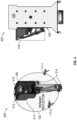
- FIG. 4 is a schematic diagram illustrating views 400 and 402 of an example of a hosted multi-reflector antenna system 410 in a stowed configuration and isolated from bus distortions, according to certain aspects of the disclosure.
- the view 400 shows the hosted multi-reflector antenna system 410 (hereinafter, antenna system 410) in a stowed configuration.
- the view 400 depicts a low CTE composite structure 412 and a thermal subsystem 414, which include an aluminum radiator, the subreflector 106, the fixtures 117 and radial flexures 214.
- the low CTE composite structure 412 and the thermal subsystem 414 can accommodate high thermal dissipation of the high-dissipation feed structure 110 of FIG. 1 .
- the view 402 shows the antenna system 410 in a stowed configuration and coupled (e.g., bolted in) to a host space vehicle (e.g., satellite) 420.
- the view 402 depicts the antenna system 410, as coupled to a bus panel 422 of the host space vehicle 420 via the fixtures 117, the hard mount 212, and the radial flexures 214, which mechanically and thermally isolate the primary reflector 102 and the optical bench, respectively, from the TED of the host space vehicle 420.
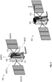
- FIG. 5 is a schematic diagram illustrating perspective views 500 and 502 of an example of a hosted multi-reflector antenna system 510 of the subject technology hosted on two different satellites.
- the hosted multi-reflector antenna system 510 (hereinafter, antenna system 510) is mounted on a host space vehicle (e.g., satellite) 520.
- the perspective view 500 also reveals a composite structure 512 that supports an aluminum thermal subsystem (i.e. radiators) 514 of the antenna system 510, which is crucial in eliminating TED and maintaining the alignment of the antenna elements, as described above.
- the antenna system 510 is mounted on a host space vehicle (e.g., satellite) 530, which is different from the host space vehicle 520.
- the antenna system 510 is designed to be mechanically and thermally independent of the host space vehicle so that it can be mounted on different host space vehicles such as the host space vehicles 520 and 530.
- the antenna system 510 is equipped to readily accommodate the thermal dissipation of a high-dissipation feed and to be able to maintain the precise antenna alignment, as discussed above.
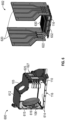
- FIG. 6 is a schematic diagram illustrating the structure of an anti-jam housing 600 and a thermal subsystem 602 of an example of a hosted multi-reflector antenna system, according to certain aspects of the disclosure.
- the anti-jam housing 600 is mounted on the optical bench 116 and includes the aperture 103, the subreflector 106, and a composite structure 612 that supports aluminum thermal radiators 620 and is internally coated with a radio-frequency (RF) absorber 614.
- the anti-jam housing 600 excludes the feed structure 110.
- the subreflector 106 is mounted to a first wall 615 of the anti-jam housing 600 via a coupling structure 616.
- the feed structure 110 including the ESA 630, is kinematically mounted on a wall 625 of the anti-jam housing 600 and the respective ESA mounting access holes are covered via closeout panels 627.
- the thermal subsystem 602 includes a thermally conductive ESA mounting plate 632 over which the ESA 630 is mounted, and it is able to transfer high thermal power (e.g., about 250 watts) generated by the ESA 630 to the aluminum thermal radiators 620 via thermally conductive heat pipes 622.
- the thermal subsystem 602 can dissipate the high thermal power generated by the ESA 630 and excludes wall 625.
- FIG. 7 is a schematic diagram illustrating a heat-dissipation mechanism in a thermal subsystem 700 of an example of a hosted multi-reflector antenna system, according to certain aspects of the disclosure.
- the thermal subsystem 700 includes the thermally conductive ESA mounting plate 632 over which the ESA 630 is mounted and the thermally conductive radiator 620.
- the heat transferred from the ESA mounting plate 632 flows into the aluminum radiator 620 and dissipates to the environment.
- the ESA mounting plate 632 and the aluminum radiator 620 are coupled to the composite structure 710 via ESA flexures 720 and radiator flexures 712, respectively.
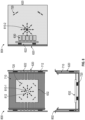
- FIG. 8 is a schematic diagram illustrating various views 800, 802 and 804 of a heat-dissipation mechanism in the thermal subsystem of an example of a hosted multi-reflector antenna system, according to certain aspects of the disclosure.
- the view 800 is a top view of the thermal subsystem 700 of FIG. 7 and shows the aluminum ESA mounting plate 632, the composite structure 710, the heat pipes 622, the aluminum radiator 620, an ESA hard-mount 810-1 and ESA flexures 720.
- the ESA hard-mount 810-1 and the ESA flexures 720 are used to mount the ESA mounting plate 632 on the composite structure 710, while keeping them mechanically decoupled, so that thermal expansion 812 of the aluminum ESA mounting plate 632 is not transferred to the composite structure 710.
- the front-view 802 is similar to the thermal subsystem 700 of FIG. 7 .
- the side-view 804 shows the ESA 630, the radiator hard-mount 810-2 and the radiator flexures 712.
- FIG. 9 is a flow diagram illustrating an example of a method 900 of providing a hosted multi-reflector antenna system (e.g., 100 of FIG. 1 ) of the subject technology.
- the method 900 includes coupling a primary reflector (e.g., 102 of FIG. 1 ) via a number of booms (e.g., 114 of FIG. 1 ) and joint structures (e.g., 118 of FIG. 1 ) to an optical bench (e.g., 116 of FIG. 1 ) (910).
- the method further includes positioning an anti-jam housing (e.g., 108 of FIG. 1 ) comprising a low CTE composite structure (e.g., 410 of FIG.
- a feed structure e.g., 110 of FIG. 1
- ESA e.g., 106 of FIG. 1
- a subreflector e.g., 104 of FIG. 1
- the hosted multi-reflector antenna system is configured to be mechanically and thermally independent of a host space vehicle (e.g., 420 of FIG.
- the subject technology may be used in various markets, including, for example, and without limitation, the satellite systems and communications systems markets.
- any specific order or hierarchy of blocks in the processes disclosed is an illustration of example approaches. Based upon design preferences, it is understood that the specific order or hierarchy of blocks in the processes may be rearranged, or that all illustrated blocks may be performed. Any of the blocks may be performed simultaneously. In one or more implementations, multitasking and parallel processing may be advantageous. Moreover, the separation of various system components in the embodiments described above should not be understood as requiring such separation in all embodiments, and it should be understood that the described program components and systems can generally be integrated together in a single hardware and software product or packaged into multiple hardware and software products.
Landscapes
- Physics & Mathematics (AREA)
- Engineering & Computer Science (AREA)
- Astronomy & Astrophysics (AREA)
- General Physics & Mathematics (AREA)
- Remote Sensing (AREA)
- Aviation & Aerospace Engineering (AREA)
- Aerials With Secondary Devices (AREA)
- Details Of Aerials (AREA)
Description
- This application claims benefit of
U.S. Provisional Application No. 63/005,135, filed April 3, 2020 - The present invention generally relates to satellite communication and, more particularly, relates to a hosted, compact, east-west, large-aperture, multi-reflector antenna system deployable with high-dissipation feed.
- Existing satellite antenna systems are commonly specific to a satellite (bus) design and are not designed to be hosted by other satellite types and/or designs. For example, the mechanical design of the antenna system and the satellite are performed in an integrated design cycle, and the antenna system lacks any payload component, such as an electronically steered antenna (ESA), to be easily hosted. In such an antenna system, antenna pointing can be degraded by the thermal distortions due to lack or insufficiency of thermal management system.
-
US Patent No.: 4521783 A discloses an offset feed horn for propagating energy toward and receiving energy from a microwave reflector antenna for use especially in satellite-ground communication systems.European Patent Application No.: 1729368 A1 discloses an antenna system comprising an antenna feed aligned with a sub-reflector and a main reflector.European Patent Application No.: 2104177 A1 discloses an antenna feed assembly. - According to various aspects of the subject technology, methods and systems are disclosed for providing a hosted multi-reflector antenna system. The disclosed hosted multi-reflector antenna system has a number of advantageous features such as compactness, east-west orientation and large aperture, and is deployable with a high-dissipation feed, as further described herein.
- In one aspect, an antenna system as disclosed in independent claim 1 is provided. Dependent claims 2-12 disclose advantageous embodiments.
- In other aspects, a method of providing an antenna system as disclosed in independent claim 13 is provided. Dependent claims 14 and 15 disclose advantageous embodiments.
- The foregoing has outlined rather broadly the features of the present disclosure so that the following detailed description can be better understood. Additional features and advantages of the disclosure, which form the subject of the claims, will be described hereinafter.
- For a more complete understanding of the present disclosure and the advantages thereof, reference is now made to the following descriptions to be taken in conjunction with the accompanying drawings describing specific aspects of the disclosure, wherein:
-
FIG. 1 is a schematic diagram illustrating an example of a hosted multi-reflector antenna system, according to certain aspects of the disclosure. -
FIG. 2A is a schematic diagram illustrating a view from a bus panel of an example of a hosted multi-reflector antenna system, according to certain aspects of the disclosure. -
FIG. 2B is a schematic diagram illustrating a perspective view of an example of a hosted multi-reflector antenna system in a stowed configuration, according to certain aspects of the disclosure. -
FIG. 3 is a schematic diagram illustrating various views of an example of a hosted multi-reflector antenna system in stowed configuration inside of a compact generic stowed volume, according to certain aspects of the disclosure. -
FIG. 4 is a schematic diagram illustrating views of an example of a hosted multireflector antenna system in a stowed configuration and isolated from bus distortions, according to certain aspects of the disclosure. -
FIG. 5 is a schematic diagram illustrating perspective views of an example of a hosted multi-reflector antenna system of the subject technology hosted on two different satellites. -
FIG. 6 is a schematic diagram illustrating the structure of an anti-jam housing and a thermal subsystem of an example of a hosted multi-reflector antenna system, according to certain aspects of the disclosure. -
FIG. 7 is a schematic diagram illustrating a heat-dissipation mechanism in a thermal subsystem of an example of a hosted multi-reflector antenna system, according to certain aspects of the disclosure. -
FIG. 8 is a schematic diagram illustrating various views of a heat-dissipation mechanism in a thermal subsystem of an example of a hosted multi-reflector antenna system and the way it is kinematically decoupled from the structural subsystem, according to certain aspects of the disclosure. -
FIG. 9 is a flow diagram illustrating an example of a method of providing a hosted multi-reflector antenna system of the subject technology. - The detailed description set forth below is intended as a description of various configurations of the subject technology and is not intended to represent the only configurations in which the subject technology can be practiced. The appended drawings are incorporated herein and constitute a part of this detailed description, which includes specific details for the purpose of providing a thorough understanding of the subject technology. However, it will be clear and apparent to those skilled in the art that the subject technology is not limited to the specific details set forth herein and can be practiced using one or more implementations. In one or more instances, well-known structures and components are shown in block-diagram form in order to avoid obscuring the concepts of the subject technology.
- In some aspects of the present technology, methods and configurations are disclosed for providing a hosted multi-reflector antenna system. The hosted multi-reflector antenna system of the subject technology is a compact, east-west (E/W) oriented, and large-aperture antenna system that is deployable with a high-dissipation feed. Accommodation of features such as compactness, E/W orientation and large aperture in a hosted deployable multi-reflector antenna system with a high payload dissipation can be difficult due to a number of challenges. For example, the hosted payload design interdependency with a host space vehicle (e.g., a satellite, also referred to as a "bus") drives cost, complexity and risk. Further, mechanical interfaces may vary depending on the host space vehicle, which can have an unknown bus distortion and an unknown thermal interface. The other challenges include precise alignment, for instance, of a laser inter-satellite link (ISL), a telescope, and so on, and antenna mechanical alignments. Furthermore, integrated thermal designs are difficult to achieve. Such thermal challenges complicate antenna and payload design due to a number of factors such as the high thermal power (e.g., ~250 watts) that can distort antenna optics, electronically steered antennas' (ESAs'), requirement of low temperatures for better performance and longer life, and anti-jam housing (faraday cage) that can complicate heat rejection.
- The existing antenna systems lack any payload component, such as an ESA, to be easily hosted. In the existing antenna systems, antenna pointing can be degraded by the bus thermal distortions due to lack or insufficiency of thermal management system.
-
FIG. 1 is a schematic diagram illustrating an example of a hostedmulti-reflector antenna system 100, according to certain aspects of the disclosure. The example hosted multi-reflector antenna system 100 (hereinafter, antenna system 100) is a compact, E/W oriented, and large aperture antenna system that can handle thermal dissipation of a high-dissipation feed (e.g., ~250 watts). Theantenna system 100 includes a number of antenna elements such as aprimary reflector 102, an aperture (iris) 103, asubreflector 104 and an ESA 106, that is part of afeed structure 110. Ananti-jam housing 108 encloses thesubreflector 104, thefeed structure 110 and the ESA 106. - The
primary reflector 102 focuses abeam 105 into theaperture 103 that is also at a focal point of thesubreflector 104, which converts the received beam into a parallel beam directed at the ESA 106. Thebeam 105 is, for example, a communication link between a host space vehicle (e.g., a space vehicle, such as a satellite) and a terrestrial station such as a satellite gateway or user terminal. Theantenna system 100 is designed to be mechanically and thermally independent of the host space vehicle so that it can be mounted on different host space vehicle. Theantenna system 100 can readily accommodate the thermal dissipation of thefeed structure 110 of a high-dissipation feed, and is able to maintain the precise antenna alignment between the antenna elements such as theprimary reflector 102, thesubreflector 104, theaperture 103, and the ESA 106, as discussed in more detail herein. - The
anti-jam housing 108 includes a composite structure and a thermal radiator layer that enable theantenna system 100 to handle the thermal dissipation of thefeed structure 110. Theanti-jam housing 108 is mounted on anoptical bench 116 that also supports theprimary reflector 102 via a reflector-support structure, including a number of (e.g., three) booms 114 (114-1, 114-2 and 114-3) and joint structures 118 (118-1, 118-2 and 118-3). Theoptical bench 116 is decoupled from the host space vehicle to reduce any thermal elastic distortion (TED) from the host space vehicle so that the alignment between theprimary reflector 102 and thesubreflector 104 can be preserved and not disturbed by the TED of the host space vehicle. The optical bench further accommodates kinematic mounts (not shown inFIG. 1 , for simplicity) that are used to couple theantenna system 100 to the host space vehicle. Thesystem 100 also includes locking fixtures 120 (e.g., 120-1, 120-2, 120-3 and 120-4 (not visible inFIG. 1 )), which can lock components of theantenna system 100, when not in use, in a stowed configuration. The locking fixture 120-1 is mounted on theanti-jam housing 108 and the locking fixtures 120-2, 120-3 and 120-4 (shown inFIG. 2B ) are mounted on theoptical bench 116 and a bus panel of the host space vehicle, respectively, viafixtures 115, 117-1, and 117-2 (not visible inFIG. 1 ). -
FIG. 2A is a schematic diagram illustrating aview 200A from a bus panel of an example of a hostedmulti-reflector antenna system 210, according to certain aspects of the disclosure. Theview 200A shows the hosted multi-reflector antenna system 210 (hereinafter, antenna system 210) from a bus panel of a host space vehicle (i.e. looking outboard from the host space vehicle) and depicts a front view of theprimary reflector 102, as it is folded back on to the locking fixtures 120 ofFIG. 1 , and a back view of theoptical bench 116. Theantenna system 210 is thesame antenna system 100 ofFIG. 1 in a folded configuration. Attached to theoptical bench 116 are ahard mount 212 and threeradial flexures 214 that are used to couple theantenna system 210 to the bus panel of a host space vehicle. The hard-mount 212 and threeradial fixtures 214, while attaching theantenna system 210 to the host space vehicle, thermally decouple theantenna system 210 from the host space vehicle so that the TED of the host space vehicle is prevented from affecting the alignment of theantenna system 210. -
FIG. 2B is a schematic diagram illustrating aperspective view 200B of an example of a hostedmulti-reflector antenna system 210 in a stowed configuration, according to certain aspects of the disclosure. Theantenna system 210 is thesame antenna system 100 ofFIG. 1 in a folded configuration, with the booms 114 folded and locked to the locking fixture 120-2, and theprimary reflector 102 is locked to the locking fixtures 120-1, 120-3 and 120-4. The locking fixtures 120-3 and 120-4 are supported by fixtures 117-1 and 117-2, respectively, which is coupled to the bus panel of the host space vehicle. The antenna system in the stowed configuration has a compact volume as shown by the dimensions inFIG. 3 below. -
FIG. 3 is a schematic diagram illustratingvarious views multi-reflector antenna system 310 in a stowed configuration, according to certain aspects of the disclosure. Theview 300 shows the compact volume of hosted multireflector antenna system 310 (hereinafter, antenna system 310), which is the same as theantenna system 100 ofFIG. 1 in a stowed configuration, and clearly depicts folding of the primary reflector. - The
view 302 is a top view that shows theantenna system 310 in the stowed configuration and depicts a dimension D1 (e.g., about 2642 mm (about 104 inches)) of theprimary reflector 312, which allows an aperture size ranging from 2286 to 2540 mm (90 to 100 inches) for theprimary reflector 312. - The
view 304 is a side view of theantenna system 310 in the stowed configuration, and depicts dimensions D2 (e.g., about 2591 mm (about 102 inches)) and D3 (e.g., about 1143 mm (45 inches)) of theantenna system 310. - The
view 306 is a side view of theantenna system 310 in the stowed configuration, and depicts dimension D4 (e.g., about 724 mm (about 28.5 inches)) of theantenna system 310. The dimensions D1, D2, D3 and D4 of theantenna system 310 support the claim of a compact volume in the stowed configuration of the antenna system of the subject technology, which is one of the advantageous features of the disclosed antenna system. -
FIG. 4 is a schematicdiagram illustrating views multi-reflector antenna system 410 in a stowed configuration and isolated from bus distortions, according to certain aspects of the disclosure. Theview 400 shows the hosted multi-reflector antenna system 410 (hereinafter, antenna system 410) in a stowed configuration. Theview 400 depicts a low CTEcomposite structure 412 and athermal subsystem 414, which include an aluminum radiator, thesubreflector 106, the fixtures 117 andradial flexures 214. The low CTEcomposite structure 412 and thethermal subsystem 414 can accommodate high thermal dissipation of the high-dissipation feed structure 110 ofFIG. 1 . - The
view 402 shows theantenna system 410 in a stowed configuration and coupled (e.g., bolted in) to a host space vehicle (e.g., satellite) 420. Theview 402 depicts theantenna system 410, as coupled to abus panel 422 of thehost space vehicle 420 via the fixtures 117, thehard mount 212, and theradial flexures 214, which mechanically and thermally isolate theprimary reflector 102 and the optical bench, respectively, from the TED of thehost space vehicle 420. -
FIG. 5 is a schematic diagram illustrating perspective views 500 and 502 of an example of a hostedmulti-reflector antenna system 510 of the subject technology hosted on two different satellites. In theperspective view 500, the hosted multi-reflector antenna system 510 (hereinafter, antenna system 510) is mounted on a host space vehicle (e.g., satellite) 520. Theperspective view 500 also reveals acomposite structure 512 that supports an aluminum thermal subsystem (i.e.
radiators) 514 of theantenna system 510, which is crucial in eliminating TED and maintaining the alignment of the antenna elements, as described above. - In the
perspective view 502, theantenna system 510 is mounted on a host space vehicle (e.g., satellite) 530, which is different from thehost space vehicle 520. Theantenna system 510 is designed to be mechanically and thermally independent of the host space vehicle so that it can be mounted on different host space vehicles such as thehost space vehicles antenna system 510 is equipped to readily accommodate the thermal dissipation of a high-dissipation feed and to be able to maintain the precise antenna alignment, as discussed above. -
FIG. 6 is a schematic diagram illustrating the structure of ananti-jam housing 600 and athermal subsystem 602 of an example of a hosted multi-reflector antenna system, according to certain aspects of the disclosure. Theanti-jam housing 600 is mounted on theoptical bench 116 and includes theaperture 103, thesubreflector 106, and acomposite structure 612 that supports aluminumthermal radiators 620 and is internally coated with a radio-frequency (RF)absorber 614. Theanti-jam housing 600 excludes thefeed structure 110. Thesubreflector 106 is mounted to afirst wall 615 of theanti-jam housing 600 via acoupling structure 616. Thefeed structure 110, including theESA 630, is kinematically mounted on awall 625 of theanti-jam housing 600 and the respective ESA mounting access holes are covered viacloseout panels 627. - The
thermal subsystem 602 includes a thermally conductiveESA mounting plate 632 over which theESA 630 is mounted, and it is able to transfer high thermal power (e.g., about 250 watts) generated by theESA 630 to the aluminumthermal radiators 620 via thermallyconductive heat pipes 622. Thethermal subsystem 602 can dissipate the high thermal power generated by theESA 630 and excludeswall 625. -
FIG. 7 is a schematic diagram illustrating a heat-dissipation mechanism in athermal subsystem 700 of an example of a hosted multi-reflector antenna system, according to certain aspects of the disclosure. Thethermal subsystem 700 includes the thermally conductiveESA mounting plate 632 over which theESA 630 is mounted and the thermallyconductive radiator 620. The heat transferred from theESA mounting plate 632 flows into thealuminum radiator 620 and dissipates to the environment. TheESA mounting plate 632 and thealuminum radiator 620 are coupled to thecomposite structure 710 viaESA flexures 720 andradiator flexures 712, respectively. -
FIG. 8 is a schematic diagram illustratingvarious views view 800 is a top view of thethermal subsystem 700 ofFIG. 7 and shows the aluminumESA mounting plate 632, thecomposite structure 710, theheat pipes 622, thealuminum radiator 620, an ESA hard-mount 810-1 andESA flexures 720. The ESA hard-mount 810-1 and theESA flexures 720 are used to mount theESA mounting plate 632 on thecomposite structure 710, while keeping them mechanically decoupled, so thatthermal expansion 812 of the aluminumESA mounting plate 632 is not transferred to thecomposite structure 710. The front-view 802 is similar to thethermal subsystem 700 ofFIG. 7 . The side-view 804 shows theESA 630, the radiator hard-mount 810-2 and theradiator flexures 712. -
FIG. 9 is a flow diagram illustrating an example of amethod 900 of providing a hosted multi-reflector antenna system (e.g., 100 ofFIG. 1 ) of the subject technology. Themethod 900 includes coupling a primary reflector (e.g., 102 ofFIG. 1 ) via a number of booms (e.g., 114 ofFIG. 1 ) and joint structures (e.g., 118 ofFIG. 1 ) to an optical bench (e.g., 116 ofFIG. 1 ) (910). The method further includes positioning an anti-jam housing (e.g., 108 ofFIG. 1 ) comprising a low CTE composite structure (e.g., 410 ofFIG. 4 ) on the optical bench (920), and coupling a feed structure (e.g., 110 ofFIG. 1 ) including an ESA (e.g., 106 ofFIG. 1 ) to a first wall (e.g., 615 ofFIG. 6 ) of the anti-jam housing (930). A subreflector (e.g., 104 ofFIG. 1 ) is coupled to a second wall (e.g., 625 ofFIG. 6 ) of the anti-jam housing opposite the first wall to direct a reflected beam of the primary reflector onto the ESA (940). The hosted multi-reflector antenna system is configured to be mechanically and thermally independent of a host space vehicle (e.g., 420 ofFIG. 4 ) to accommodate thermal dissipation of the feed structure (e.g., via 632 ofFIG. 6 ) and to maintain a precise antenna system alignment (e.g., alignment of 102, 104 and 106 ofFIG. 1 ) (950). - In some aspects, the subject technology may be used in various markets, including, for example, and without limitation, the satellite systems and communications systems markets.
- Those of skill in the art would appreciate that the various illustrative blocks, modules, elements, components, methods, and algorithms described herein may be implemented as electronic hardware, computer software, or combinations of both. To illustrate this interchangeability of hardware and software, various illustrative blocks, modules, elements, components, methods, and algorithms have been described above generally in terms of their functionality. Whether such functionality is implemented as hardware or software depends upon the particular application and design constraints imposed on the overall system. Skilled artisans may implement the described functionality in varying ways for each particular application. Various components and blocks may be arranged differently (e.g., arranged in a different order, or partitioned in a different way), all without departing from the scope of the subject technology.
- It is understood that any specific order or hierarchy of blocks in the processes disclosed is an illustration of example approaches. Based upon design preferences, it is understood that the specific order or hierarchy of blocks in the processes may be rearranged, or that all illustrated blocks may be performed. Any of the blocks may be performed simultaneously. In one or more implementations, multitasking and parallel processing may be advantageous. Moreover, the separation of various system components in the embodiments described above should not be understood as requiring such separation in all embodiments, and it should be understood that the described program components and systems can generally be integrated together in a single hardware and software product or packaged into multiple hardware and software products.
- The description of the subject technology is provided to enable any person skilled in the art to practice the various aspects described herein. While the subject technology has been particularly described with reference to the various figures and aspects, it should be understood that these are for illustration purposes only and should not be taken as limiting the scope of the subject technology.
- A reference to an element in the singular is not intended to mean "one and only one" unless specifically stated, but rather "one or more." The term "some" refers to one or more. Moreover, nothing disclosed herein is intended to be dedicated to the public regardless of whether such disclosure is explicitly recited in the above description.
- Although the invention has been described with reference to the disclosed aspects, one having ordinary skill in the art will readily appreciate that these aspects are only illustrative of the invention. It should be understood that various modifications can be made without departing from the scope of the invention. Furthermore, no limitations are intended to the details of construction or design herein shown, other than as described in the claims below. It is therefore evident that the particular illustrative aspects disclosed above may be altered, combined, or modified, and all such variations are considered within the scope of the present invention. While compositions and methods are described in terms of "comprising," "containing," or "including" various components or steps, the compositions and methods can also "consist essentially of' or "consist of' the various components and operations. All numbers and ranges disclosed above can vary by some amount. Whenever a numerical range with a lower limit and an upper limit is disclosed, any number and any subrange falling within the broader range is specifically disclosed. Also, the terms in the claims have their plain, ordinary meanings unless otherwise explicitly and clearly defined by the patentee.
Claims (15)
- An antenna system (100, 210, 310, 410, 510) for a host space vehicle (520, 530), the antenna system (100, 210, 310, 410, 510) comprising:a primary reflector (102, 312);a feed structure (110) including an electronically steered antenna, ESA, (106);a subreflector (104) configured to direct a reflected beam of the primary reflector (102, 312) onto the ESA (106) and direct a reflected beam from the ESA (106) to the primary reflector (102, 312); andan anti-jam housing (108, 600) enclosing the subreflector (104) and the ESA (106), and comprising an aperture (103),wherein:
the antenna system (100, 210, 310, 410, 510) is configured to:
be thermo-elastically decoupled and thermally self-sufficient from the host space vehicle (520, 530), accommodate a thermal dissipation of the feed structure (110), and maintain a precise antenna alignment. - The antenna system (100, 210, 310, 410, 510) of claim 1, further comprising an optical bench (116) that is kinematically mountable to the host space vehicle (520, 530) and configured to reduce a thermal elastic distortion, TED, from the host space vehicle (520, 530).
- The antenna system (100, 210, 310, 410, 510) of claim 2, wherein the optical bench (116) is further configured to accommodate kinematic mounts for coupling the antenna system (100, 210, 310, 410, 510) to the host space vehicle (520, 530).
- The antenna system (100, 210, 310, 410, 510) of claim 2, wherein the optical bench (116) is further configured to maintain an alignment between the primary reflector (102, 312) to the aperture (103) of the anti-jam housing (108, 600).
- The antenna system of claim 1, wherein the anti-jam housing (108, 600) comprises composite structure with a low coefficient of thermal expansion, CTE, that is configured to maintain an alignment between the primary reflector (102, 312), the subreflector (104) and the ESA (106) by reducing TED resulting from a high thermal dissipation of the feed structure (110).
- The antenna system (100, 210, 310, 410, 510) of claim 1, wherein the primary reflector (102, 312) is a large-aperture reflector with an aperture size ranging from 2286 to 2540 mm (90 to 100 inches), and further comprising a mechanism for extending a vertex of the large-aperture reflector to a distance equal to a focal length of the primary reflector (102, 312) from the aperture (103) of the anti-jam housing (108, 600).
- The antenna system (100, 210, 310, 410, 510) of claim 6, wherein the mechanism for extending the vertex of the large-aperture reflector is further configured to fold the antenna system (100, 210, 310, 410, 510) into a compact-volume stowed package when not deployed.
- The antenna system (100, 210, 310, 410, 510) of claim 1, wherein the anti-jam housing (108, 600) is enclosed in a thermal subsystem (602, 700) made of aluminum.
- The antenna system (100, 210, 310, 410, 510) of claim 1, further comprising a kinematic mount comprising a hard mount and three radial fixtures to mount the antenna system (100, 210, 310, 410, 510) to the host space vehicle (520, 530).
- The antenna system (100, 210, 310, 410, 510) of claim 8, wherein the thermal subsystem (602, 700) comprises an aluminum thermal radiator and accommodating the thermal dissipation of the feed structure (110) is achieved by using an ESA kinematic restraint and a thermal radiator kinematic restraint.
- The antenna system (100, 210, 310, 410, 510) of claim 10, wherein the ESA kinematic restraint is configured to decouple ESA thermal expansion from a low CTE composite structure of the anti-jam housing (108, 600) while maintaining alignment of the ESA (106) with the subreflector (104) and the primary reflector (102, 312).
- The antenna system (100, 210, 310, 410, 510) of claim 10, wherein the thermal radiator kinematic restraint is configured to decouple a thermal expansion of the aluminum radiator from a low CTE composite structure of the anti-jam housing (108, 600) to preserve an antenna system (100, 210, 310, 410, 510) alignment.
- A method of providing an antenna system (100, 210, 310, 410, 510) for a host space vehicle (520, 530), the method comprising:coupling a primary reflector (102, 312) via a number of booms and joint structures to an optical bench (116);positioning an anti-jam housing (108, 600) comprising an aperture (103) and a low CTE composite structure on the optical bench (116);coupling a feed structure (110) including an ESA (106) to a first wall of the anti-jam housing (108, 600);coupling a subreflector (104) to a second wall of the anti-jam housing (108, 600) opposite the first wall to direct a reflected beam of the primary reflector (102, 312) onto the ESA (106) and direct a reflected beam from the ESA (106) to the primary reflector (102, 312);configuring the hosted multi-reflector antenna system (100, 210, 310, 410, 510) to:be thermo-elastically decoupled and thermally self-sufficient from the host space vehicle (520, 530);accommodate a thermal dissipation of the feed structure (110); andmaintain a precise antenna system alignment.
- The method of claim 13, further comprising configuring the optical bench to accommodate kinematic mounts for coupling the antenna system to the host space vehicle and to maintain an alignment between the primary reflector to the aperture (103) of the anti-jam housing (108, 600).
- The method of claim 13, wherein accommodating the thermal dissipation of the feed structure is achieved by: using an ESA kinematic restraint to decouple a thermal expansion of the ESA from the low CTE composite structure while maintaining alignment of the ESA with the subreflector and the primary reflector; or using a thermal radiator kinematic restraint to decouple a thermal expansion of an aluminum radiator of the anti-jam housing from the low CTE composite structure to preserve an antenna system alignment.
Applications Claiming Priority (3)
| Application Number | Priority Date | Filing Date | Title |
|---|---|---|---|
| US202063005135P | 2020-04-03 | 2020-04-03 | |
| US17/148,474 US11398682B2 (en) | 2020-04-03 | 2021-01-13 | Hosted, compact, large-aperture, multi-reflector antenna system deployable with high-dissipation feed |
| PCT/US2021/025586 WO2021203004A1 (en) | 2020-04-03 | 2021-04-02 | Hosted, compact, large-aperture, multi-reflector antenna system deployable with high-dissipation feed |
Publications (3)
| Publication Number | Publication Date |
|---|---|
| EP4128436A1 EP4128436A1 (en) | 2023-02-08 |
| EP4128436A4 EP4128436A4 (en) | 2024-04-24 |
| EP4128436B1 true EP4128436B1 (en) | 2025-06-11 |
Family
ID=77922800
Family Applications (1)
| Application Number | Title | Priority Date | Filing Date |
|---|---|---|---|
| EP21780899.7A Active EP4128436B1 (en) | 2020-04-03 | 2021-04-02 | Hosted, compact, large-aperture, multi-reflector antenna system deployable with high-dissipation feed |
Country Status (4)
| Country | Link |
|---|---|
| US (1) | US11398682B2 (en) |
| EP (1) | EP4128436B1 (en) |
| CA (1) | CA3181390C (en) |
| WO (1) | WO2021203004A1 (en) |
Families Citing this family (2)
| Publication number | Priority date | Publication date | Assignee | Title |
|---|---|---|---|---|
| US12283750B2 (en) * | 2018-11-08 | 2025-04-22 | Orbit Communication Systems Ltd. | Low profile multi band antenna system |
| CN115642385B (en) * | 2022-09-26 | 2026-03-06 | 西安空间无线电技术研究所 | A thermally decoupled metal support structure for a spaceborne multi-beam antenna feed array |
Family Cites Families (11)
| Publication number | Priority date | Publication date | Assignee | Title |
|---|---|---|---|---|
| US4521783A (en) * | 1982-09-27 | 1985-06-04 | Ford Aerospace & Communications Corporation | Offset microwave feed horn for producing focused beam having reduced sidelobe radiation |
| DE10239303B4 (en) * | 2002-08-27 | 2006-08-03 | Siemens Ag | Energy self-modulated backscatter transponder |
| US20040196203A1 (en) * | 2002-09-11 | 2004-10-07 | Lockheed Martin Corporation | Partly interleaved phased arrays with different antenna elements in central and outer region |
| US7205949B2 (en) * | 2005-05-31 | 2007-04-17 | Harris Corporation | Dual reflector antenna and associated methods |
| EP2104177A1 (en) * | 2008-03-18 | 2009-09-23 | Astrium Limited | Antenna feed assembly |
| EP2110884B1 (en) * | 2008-04-15 | 2013-05-29 | Sub10 Systems Limited | Surface-mountable antenna with waveguide connector function, communication system, adaptor and arrangement comprising the antenna device |
| FR2944155B1 (en) * | 2009-04-02 | 2016-05-13 | Astrium Sas | RADIOELECTRONIC ANTENNA WITH IMPROVED DECOUPLING CORNERS |
| US9520637B2 (en) * | 2012-08-27 | 2016-12-13 | Kvh Industries, Inc. | Agile diverse polarization multi-frequency band antenna feed with rotatable integrated distributed transceivers |
| US20150069187A1 (en) * | 2013-09-09 | 2015-03-12 | Lockheed Martin Corporation | Hosted instrument radiator system |
| US10263342B2 (en) * | 2013-10-15 | 2019-04-16 | Northrop Grumman Systems Corporation | Reflectarray antenna system |
| US10862189B1 (en) * | 2016-11-10 | 2020-12-08 | United States Of America As Represented By The Administrator Of National Aeronautics And Space Administration | Near earth and deep space communications system |
-
2021
- 2021-01-13 US US17/148,474 patent/US11398682B2/en active Active
- 2021-04-02 EP EP21780899.7A patent/EP4128436B1/en active Active
- 2021-04-02 WO PCT/US2021/025586 patent/WO2021203004A1/en not_active Ceased
- 2021-04-02 CA CA3181390A patent/CA3181390C/en active Active
Also Published As
| Publication number | Publication date |
|---|---|
| US20210313684A1 (en) | 2021-10-07 |
| EP4128436A4 (en) | 2024-04-24 |
| CA3181390A1 (en) | 2021-10-07 |
| WO2021203004A1 (en) | 2021-10-07 |
| CA3181390C (en) | 2023-07-11 |
| US11398682B2 (en) | 2022-07-26 |
| EP4128436A1 (en) | 2023-02-08 |
Similar Documents
| Publication | Publication Date | Title |
|---|---|---|
| KR20220023765A (en) | Thermal management systems for structures in space | |
| JPH0633697Y2 (en) | Multi-communication satellite orbit spacecraft | |
| JP6024061B2 (en) | Large and robust deployable structures and methods for deploying and locking such structures | |
| EP3353908B1 (en) | Hybrid communications assembly for spacecraft | |
| CA3181390C (en) | Hosted, compact, large-aperture, multi-reflector antenna system deployable with high-dissipation feed | |
| JP6659737B2 (en) | Integrated antenna and RF payload for low cost intersatellite link using superelliptical antenna aperture with single axis gimbal | |
| US20150069187A1 (en) | Hosted instrument radiator system | |
| US7036772B2 (en) | Spacecraft with extensible radiators | |
| US10097285B2 (en) | Single E-probe reduced aperture waveguide coupler | |
| CA2718070A1 (en) | Antenna feed assembly | |
| US7762499B1 (en) | Independent East/West thermal management system | |
| US20230322419A1 (en) | Radiating coupling heat pipe | |
| CA2812448C (en) | Multiple-reflector antenna for telecommunications satellites | |
| Kroon et al. | Articulated deployment system for antenna reflectors | |
| US10862189B1 (en) | Near earth and deep space communications system | |
| US10454595B2 (en) | Single E-probe field aperture coupler | |
| Amyotte et al. | Antennas for satellite communications | |
| Mini et al. | European large deployable antenna: development status and applications | |
| CN120327817B (en) | Protective satellites and spacecraft | |
| EP2104177A1 (en) | Antenna feed assembly | |
| CN121769520A (en) | Offset-fed dual-antenna combination configuration with common reference for sub-reflector and feed source | |
| Mini et al. | European large deployable antenna (12 meter): Development status and applications | |
| Toland et al. | Novel three-axis beam waveguide feed for space-based millimeter-wave applications |
Legal Events
| Date | Code | Title | Description |
|---|---|---|---|
| STAA | Information on the status of an ep patent application or granted ep patent |
Free format text: STATUS: THE INTERNATIONAL PUBLICATION HAS BEEN MADE |
|
| PUAI | Public reference made under article 153(3) epc to a published international application that has entered the european phase |
Free format text: ORIGINAL CODE: 0009012 |
|
| STAA | Information on the status of an ep patent application or granted ep patent |
Free format text: STATUS: REQUEST FOR EXAMINATION WAS MADE |
|
| 17P | Request for examination filed |
Effective date: 20221101 |
|
| AK | Designated contracting states |
Kind code of ref document: A1 Designated state(s): AL AT BE BG CH CY CZ DE DK EE ES FI FR GB GR HR HU IE IS IT LI LT LU LV MC MK MT NL NO PL PT RO RS SE SI SK SM TR |
|
| DAV | Request for validation of the european patent (deleted) | ||
| DAX | Request for extension of the european patent (deleted) | ||
| REG | Reference to a national code |
Ref legal event code: R079 Free format text: PREVIOUS MAIN CLASS: H01Q0001280000 Ref country code: DE Ref legal event code: R079 Ref document number: 602021032187 Country of ref document: DE Free format text: PREVIOUS MAIN CLASS: H01Q0001280000 Ipc: H01Q0001020000 |
|
| A4 | Supplementary search report drawn up and despatched |
Effective date: 20240325 |
|
| RIC1 | Information provided on ipc code assigned before grant |
Ipc: H01Q 19/19 20060101ALI20240319BHEP Ipc: H01Q 3/26 20060101ALI20240319BHEP Ipc: H01Q 1/28 20060101ALI20240319BHEP Ipc: H01Q 1/08 20060101ALI20240319BHEP Ipc: H01Q 1/02 20060101AFI20240319BHEP |
|
| GRAP | Despatch of communication of intention to grant a patent |
Free format text: ORIGINAL CODE: EPIDOSNIGR1 |
|
| STAA | Information on the status of an ep patent application or granted ep patent |
Free format text: STATUS: GRANT OF PATENT IS INTENDED |
|
| INTG | Intention to grant announced |
Effective date: 20250123 |
|
| GRAS | Grant fee paid |
Free format text: ORIGINAL CODE: EPIDOSNIGR3 |
|
| GRAA | (expected) grant |
Free format text: ORIGINAL CODE: 0009210 |
|
| STAA | Information on the status of an ep patent application or granted ep patent |
Free format text: STATUS: THE PATENT HAS BEEN GRANTED |
|
| P01 | Opt-out of the competence of the unified patent court (upc) registered |
Free format text: CASE NUMBER: APP_18794/2025 Effective date: 20250417 |
|
| AK | Designated contracting states |
Kind code of ref document: B1 Designated state(s): AL AT BE BG CH CY CZ DE DK EE ES FI FR GB GR HR HU IE IS IT LI LT LU LV MC MK MT NL NO PL PT RO RS SE SI SK SM TR |
|
| REG | Reference to a national code |
Ref country code: GB Ref legal event code: FG4D |
|
| REG | Reference to a national code |
Ref country code: CH Ref legal event code: EP |
|
| REG | Reference to a national code |
Ref country code: IE Ref legal event code: FG4D |
|
| REG | Reference to a national code |
Ref country code: DE Ref legal event code: R096 Ref document number: 602021032187 Country of ref document: DE |
|
| PG25 | Lapsed in a contracting state [announced via postgrant information from national office to epo] |
Ref country code: FI Free format text: LAPSE BECAUSE OF FAILURE TO SUBMIT A TRANSLATION OF THE DESCRIPTION OR TO PAY THE FEE WITHIN THE PRESCRIBED TIME-LIMIT Effective date: 20250611 Ref country code: ES Free format text: LAPSE BECAUSE OF FAILURE TO SUBMIT A TRANSLATION OF THE DESCRIPTION OR TO PAY THE FEE WITHIN THE PRESCRIBED TIME-LIMIT Effective date: 20250611 |
|
| REG | Reference to a national code |
Ref country code: LT Ref legal event code: MG9D |
|
| PG25 | Lapsed in a contracting state [announced via postgrant information from national office to epo] |
Ref country code: NO Free format text: LAPSE BECAUSE OF FAILURE TO SUBMIT A TRANSLATION OF THE DESCRIPTION OR TO PAY THE FEE WITHIN THE PRESCRIBED TIME-LIMIT Effective date: 20250911 Ref country code: GR Free format text: LAPSE BECAUSE OF FAILURE TO SUBMIT A TRANSLATION OF THE DESCRIPTION OR TO PAY THE FEE WITHIN THE PRESCRIBED TIME-LIMIT Effective date: 20250912 |
|
| REG | Reference to a national code |
Ref country code: NL Ref legal event code: MP Effective date: 20250611 |
|
| PG25 | Lapsed in a contracting state [announced via postgrant information from national office to epo] |
Ref country code: BG Free format text: LAPSE BECAUSE OF FAILURE TO SUBMIT A TRANSLATION OF THE DESCRIPTION OR TO PAY THE FEE WITHIN THE PRESCRIBED TIME-LIMIT Effective date: 20250611 |
|
| PG25 | Lapsed in a contracting state [announced via postgrant information from national office to epo] |
Ref country code: HR Free format text: LAPSE BECAUSE OF FAILURE TO SUBMIT A TRANSLATION OF THE DESCRIPTION OR TO PAY THE FEE WITHIN THE PRESCRIBED TIME-LIMIT Effective date: 20250611 |
|
| PG25 | Lapsed in a contracting state [announced via postgrant information from national office to epo] |
Ref country code: RS Free format text: LAPSE BECAUSE OF FAILURE TO SUBMIT A TRANSLATION OF THE DESCRIPTION OR TO PAY THE FEE WITHIN THE PRESCRIBED TIME-LIMIT Effective date: 20250911 |
|
| PG25 | Lapsed in a contracting state [announced via postgrant information from national office to epo] |
Ref country code: LV Free format text: LAPSE BECAUSE OF FAILURE TO SUBMIT A TRANSLATION OF THE DESCRIPTION OR TO PAY THE FEE WITHIN THE PRESCRIBED TIME-LIMIT Effective date: 20250611 |
|
| PG25 | Lapsed in a contracting state [announced via postgrant information from national office to epo] |
Ref country code: NL Free format text: LAPSE BECAUSE OF FAILURE TO SUBMIT A TRANSLATION OF THE DESCRIPTION OR TO PAY THE FEE WITHIN THE PRESCRIBED TIME-LIMIT Effective date: 20250611 |
|
| PG25 | Lapsed in a contracting state [announced via postgrant information from national office to epo] |
Ref country code: PT Free format text: LAPSE BECAUSE OF FAILURE TO SUBMIT A TRANSLATION OF THE DESCRIPTION OR TO PAY THE FEE WITHIN THE PRESCRIBED TIME-LIMIT Effective date: 20251013 |
|
| REG | Reference to a national code |
Ref country code: AT Ref legal event code: MK05 Ref document number: 1803009 Country of ref document: AT Kind code of ref document: T Effective date: 20250611 |
|
| PG25 | Lapsed in a contracting state [announced via postgrant information from national office to epo] |
Ref country code: IS Free format text: LAPSE BECAUSE OF FAILURE TO SUBMIT A TRANSLATION OF THE DESCRIPTION OR TO PAY THE FEE WITHIN THE PRESCRIBED TIME-LIMIT Effective date: 20251011 |
|
| PG25 | Lapsed in a contracting state [announced via postgrant information from national office to epo] |
Ref country code: SM Free format text: LAPSE BECAUSE OF FAILURE TO SUBMIT A TRANSLATION OF THE DESCRIPTION OR TO PAY THE FEE WITHIN THE PRESCRIBED TIME-LIMIT Effective date: 20250611 Ref country code: AT Free format text: LAPSE BECAUSE OF FAILURE TO SUBMIT A TRANSLATION OF THE DESCRIPTION OR TO PAY THE FEE WITHIN THE PRESCRIBED TIME-LIMIT Effective date: 20250611 |
|
| PG25 | Lapsed in a contracting state [announced via postgrant information from national office to epo] |
Ref country code: CZ Free format text: LAPSE BECAUSE OF FAILURE TO SUBMIT A TRANSLATION OF THE DESCRIPTION OR TO PAY THE FEE WITHIN THE PRESCRIBED TIME-LIMIT Effective date: 20250611 |
|
| PG25 | Lapsed in a contracting state [announced via postgrant information from national office to epo] |
Ref country code: PL Free format text: LAPSE BECAUSE OF FAILURE TO SUBMIT A TRANSLATION OF THE DESCRIPTION OR TO PAY THE FEE WITHIN THE PRESCRIBED TIME-LIMIT Effective date: 20250611 |
|
| PG25 | Lapsed in a contracting state [announced via postgrant information from national office to epo] |
Ref country code: EE Free format text: LAPSE BECAUSE OF FAILURE TO SUBMIT A TRANSLATION OF THE DESCRIPTION OR TO PAY THE FEE WITHIN THE PRESCRIBED TIME-LIMIT Effective date: 20250611 |
|
| PG25 | Lapsed in a contracting state [announced via postgrant information from national office to epo] |
Ref country code: SK Free format text: LAPSE BECAUSE OF FAILURE TO SUBMIT A TRANSLATION OF THE DESCRIPTION OR TO PAY THE FEE WITHIN THE PRESCRIBED TIME-LIMIT Effective date: 20250611 |
|
| REG | Reference to a national code |
Ref country code: DE Ref legal event code: R097 Ref document number: 602021032187 Country of ref document: DE |
|
| PG25 | Lapsed in a contracting state [announced via postgrant information from national office to epo] |
Ref country code: DK Free format text: LAPSE BECAUSE OF FAILURE TO SUBMIT A TRANSLATION OF THE DESCRIPTION OR TO PAY THE FEE WITHIN THE PRESCRIBED TIME-LIMIT Effective date: 20250611 |
|
| PG25 | Lapsed in a contracting state [announced via postgrant information from national office to epo] |
Ref country code: IT Free format text: LAPSE BECAUSE OF FAILURE TO SUBMIT A TRANSLATION OF THE DESCRIPTION OR TO PAY THE FEE WITHIN THE PRESCRIBED TIME-LIMIT Effective date: 20250611 |
|
| PLBE | No opposition filed within time limit |
Free format text: ORIGINAL CODE: 0009261 |
|
| STAA | Information on the status of an ep patent application or granted ep patent |
Free format text: STATUS: NO OPPOSITION FILED WITHIN TIME LIMIT |
|
| REG | Reference to a national code |
Ref country code: CH Ref legal event code: L10 Free format text: ST27 STATUS EVENT CODE: U-0-0-L10-L00 (AS PROVIDED BY THE NATIONAL OFFICE) Effective date: 20260423 |