EP4127678B1 - Method for selection of raman excitation wavelengths in multi-source raman probe - Google Patents
Method for selection of raman excitation wavelengths in multi-source raman probe Download PDFInfo
- Publication number
- EP4127678B1 EP4127678B1 EP21717987.8A EP21717987A EP4127678B1 EP 4127678 B1 EP4127678 B1 EP 4127678B1 EP 21717987 A EP21717987 A EP 21717987A EP 4127678 B1 EP4127678 B1 EP 4127678B1
- Authority
- EP
- European Patent Office
- Prior art keywords
- raman
- wavelength
- excitation wavelength
- light
- excitation
- Prior art date
- Legal status (The legal status is an assumption and is not a legal conclusion. Google has not performed a legal analysis and makes no representation as to the accuracy of the status listed.)
- Active
Links
Images






Classifications
-
- G—PHYSICS
- G01—MEASURING; TESTING
- G01N—INVESTIGATING OR ANALYSING MATERIALS BY DETERMINING THEIR CHEMICAL OR PHYSICAL PROPERTIES
- G01N21/00—Investigating or analysing materials by the use of optical means, i.e. using sub-millimetre waves, infrared, visible or ultraviolet light
- G01N21/62—Systems in which the material investigated is excited whereby it emits light or causes a change in wavelength of the incident light
- G01N21/63—Systems in which the material investigated is excited whereby it emits light or causes a change in wavelength of the incident light optically excited
- G01N21/65—Raman scattering
-
- G—PHYSICS
- G01—MEASURING; TESTING
- G01J—MEASUREMENT OF INTENSITY, VELOCITY, SPECTRAL CONTENT, POLARISATION, PHASE OR PULSE CHARACTERISTICS OF INFRARED, VISIBLE OR ULTRAVIOLET LIGHT; COLORIMETRY; RADIATION PYROMETRY
- G01J3/00—Spectrometry; Spectrophotometry; Monochromators; Measuring colours
- G01J3/02—Details
- G01J3/027—Control of working procedures of a spectrometer; Failure detection; Bandwidth calculation
-
- G—PHYSICS
- G01—MEASURING; TESTING
- G01J—MEASUREMENT OF INTENSITY, VELOCITY, SPECTRAL CONTENT, POLARISATION, PHASE OR PULSE CHARACTERISTICS OF INFRARED, VISIBLE OR ULTRAVIOLET LIGHT; COLORIMETRY; RADIATION PYROMETRY
- G01J3/00—Spectrometry; Spectrophotometry; Monochromators; Measuring colours
- G01J3/28—Investigating the spectrum
- G01J3/44—Raman spectrometry; Scattering spectrometry ; Fluorescence spectrometry
-
- G—PHYSICS
- G01—MEASURING; TESTING
- G01J—MEASUREMENT OF INTENSITY, VELOCITY, SPECTRAL CONTENT, POLARISATION, PHASE OR PULSE CHARACTERISTICS OF INFRARED, VISIBLE OR ULTRAVIOLET LIGHT; COLORIMETRY; RADIATION PYROMETRY
- G01J3/00—Spectrometry; Spectrophotometry; Monochromators; Measuring colours
- G01J3/28—Investigating the spectrum
- G01J3/44—Raman spectrometry; Scattering spectrometry ; Fluorescence spectrometry
- G01J2003/4424—Fluorescence correction for Raman spectrometry
Definitions
- This invention relates to the field of spectroscopy and more particularly to a compact Raman spectroscopy system and method for providing enhanced quantitative analysis for process control.
- Raman spectroscopy is a well-known technique that can be used to observe vibrational, rotational and other low-frequency modes in molecules.
- Raman scattering is an inelastic process whereby monochromatic light typically provided by a laser interacts with molecular vibrations, phonons or other excitations resulting in the energy of the laser photons being shifted up or down. Due to conservation of energy the emitted photon gains or loses energy equal to energy of the vibrational state.
- Raman measurements suffer from fluorescence, which forces usage of longer wavelength (lower energy) excitation lasers to mitigate against the fluorescent signal overwhelming the Raman signal, thereby making the latter impossible to extract.
- Usage of longer excitation wavelengths facilitates extraction of Raman signals from fluorescent samples but at a cost of reduced sensitivity in the silicon CCD detectors that capture spectrometer signals.
- Each of the referred-to references focuses on capture of multiple Raman spectra using a dual-laser configuration.
- the references fail to disclose the means for selecting wavelengths used in the spectral analysis based on the material selected and the characteristics of the spectrometer utilized.
- a compact Raman probe and spectrometer system that provides for improved quantitative analysis using two or more probe laser wavelengths and a method for selecting the laser probe wavelengths to enhance a quantitative analysis of a target material under investigation for different applications.
- the Raman spectral concatenation concept described herein allows use of a single, relatively compact spectrometer to collect both fingerprint and stretch Raman spectra (i.e., collected Raman wavelengths) and a method for selecting the laser source wavelengths to provide for enhanced quantitative analysis of target material under investigation.
- the fingerprint spectrum is captured using one excitation wavelength
- the stretch spectrum is captured using a second wavelength selected based on a quantum efficiency of the spectrometer and the first wavelength.
- the selection of one or more of the laser source wavelengths in the manner disclosed, herein, provides for enhanced signal to noise ratio so as to enhance the performance of a quantitative analysis of a target material under investigation.
- a compact dual-wavelength Raman probe configured to provide two or more separate laser wavelengths selected in a manner to provide enhanced quantitative analysis of material under investigation is disclosed.
- two laser sources may be integrated within the housing of (or internal to) a Raman probe and or external to the housing of a Raman probe.
- Described herein are embodiments in which light output emitted by two lasers sources may be combined in a common optical path, wherein the emitted light may be combined using either wavelength beam combining with dichroic mirrors or geometric beam combining.
- the wavelengths of the probe lasers used in a dual-wavelength Raman probe are selected based on the quantum efficiency of a spectrometer comprising a single detector array (silicon, InGaAs, or any other detector array) within the spectrometer.
- the quantum efficiency of a detector is a measure of the ratio of collected to incident photons versus wavelength and is a common characteristic of spectrometers supplied by manufacturers.
- the invention is directed to a method for determining a first excitation wavelength and a second excitation wavelength for use in a dual laser spectrometer system.
- a dual laser spectrometer system comprises a first laser source configured to emit a first excitation wavelength and a second laser source configured to emit a second excitation wavelength; and a spectrometer configured to receive a first Raman signal and a second Raman signal, wherein said first Raman signal is associated with said first excitation wavelength and said second Raman signal is associated with said second excitation wavelength.
- Said method comprises
- a diagnostic system comprising, optionally, a spectrometer, said spectrometer having a known quantum efficiency; and a Raman probe device configured to provide Raman light wavelengths to the spectrometer, said Raman light wavelengths being generated in response to an excitation light illuminating a target object, wherein said excitation light comprises at least one of a first light comprising a first wavelength, ⁇ p 2 , and a second light comprising a second wavelength, ⁇ p 1 , said first excitation wavelength selected based on at least one characteristic of said target object, and said second excitation wavelength determined based on said first excitation wavelength and a wavelength associated with substantially a peak value of said known quantum efficiency.
- the diagnostic system may comprise a control unit adapted to determine the second excitation wavelength, preferably adapted to execute the method substantially as described above.
- Described herein is a computer programm comprising instructions to cause the system as described above to determine the second excitation wavelength, preferably by executing the method substantially as described above.
- the probe laser wavelengths are determined for different applications based on the quantum efficiency of the spectrometer and the material in a target object such that a desired Raman spectra is substantially coincident to a peak of the detector quantum efficiency and, hence, achieving higher signal to noise ratio.
- Raman excitation wavelengths based on the quantum efficiency of the spectrometer allows shifting of both the fingerprint and stretch regions of the Raman spectrum to wavelengths at which silicon detectors (or similar detectors) have relatively high quantum efficiency.
- Raman spectra of each of the two laser sources may be captured separately and subsequently concatenated, or stitched together, to provide a single spectral scan encompassing the entire range of data, including the fingerprint and stretch regions, wherein the signal-to-noise ratio of the Raman signal in the stretch region is enhanced.
- the compact dual-wavelength Raman probe may include optics to configure the output beam of each laser source to have a circular, an elliptical or an elongated cross-section, approximating a shape of a circular or a shape of the elongated emission region of the laser near-field.
- the light generated by the laser sources is emitted toward a target object or material under investigation and the resultant scattered signal light is transmitted by the compact Raman probe via an optical beam that may also have a corresponding elliptical cross-section.
- the excitation and collection paths may be co-linear (i.e., co-aligned) or separate (e.g., spatially-offset (see USPPA 20080076985) or transmission geometry (see USP 8085396 )).
- An optical fiber incorporating a core having dimensions approximating those of the returned scattered light beam transmits the returned scattered light to the entrance aperture of a spectrometer.
- the dual-wavelength Raman probe may include external cavity lasers (ECLs) that may be integrated into the probe as wavelength-stabilized laser sources. See, for example, US 9,059,555 B2 , "Wavelength-Stabilized Diode Laser”. Or may retain the ECLs external to the Raman probe.
- ECLs external cavity lasers
- a distributed Bragg reflector (DBR) or distributed feedback (DFB) lasers may comprise a wavelength-stabilized laser source that may be integrally incorporated into the Raman probe or may be retained external to the Raman probe.
- DBR distributed Bragg reflector
- DFB distributed feedback
- the light emitted by a laser may be used as the pump source for a non-linear optical (NLO) conversion to produce a different wavelength, e.g., by second-harmonic generation (SHG), third-harmonic generation (THG), or any other non-linear optical process.
- NLO non-linear optical
- the selection of a second wavelength is based, in part, on a first wavelength and a spectral efficiency of the spectrometer used to collect the Raman signal, as disclosed elsewhere herein.
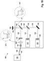
- FIG. 1A illustrates a block diagram of an exemplary embodiment of a compact dual-wavelength co-aligned/reflective Raman probe configuration where the light outputted by corresponding ones of the illustrated two laser sources are combined along a same optical path using wavelength beam combining with a dichroic mirror, which is similar to the configuration shown in, and disclosed with regard to FIG. 5 of US 10,359,313 B1 , which discloses the use of diode lasers as the light sources in Raman spectroscopy.
- a dual wavelength Raman probe 100 includes a housing 105 and two external light sources 110 and 120, (hereinafter referred to as lasers or laser sources.
- the light sources 110 and 120 may similarly be non-lasing sources, e.g., a super luminescent diode) coupled via optical fibers 113 and 123, respectively, to the internal optics within housing 105.
- the lasers 110 and 120 may emit light in a single spatial mode or in multiple spatial modes.
- Optical couples 111, 112, 121, and 122 are known devices for coupling optical fibers to equipment or devices.
- the laser sources 110 and 120 may be any laser device or system; preferably laser sources 110 and 120 are wavelength-stabilized laser sources having narrow bandwidth.
- One class of lasers that may be used as a wavelength-stabilized laser source is an external cavity laser. See, for example, US 9,059,555 B2 and US 9,577,409 B1 , which are assigned to the assignee of the instant application, and describe exemplary external wavelength stabilized diode lasers.
- Sources 110, 120 may also be semiconductor lasers that incorporate gratings within their structure, such as a distributed feedback (DFB) or distributed Bragg reflector (DBR) laser.
- DFB distributed feedback
- DBR distributed Bragg reflector
- Laser sources 110, 120 may also be a DFB or DBR laser coupled to a non-linear optical element for second- or third-harmonic generation of shorter wavelength laser light, as is well-known in the art.
- the compact dual-wavelength Raman probe 100 further includes optics 115, 125 to configure the output beam of the laser sources 110, 120.
- Exemplary components shown in FIG. 1A are lenses 116, 117, and 118 (optics 115) to reshape the optical beam associated with laser 110 to form, for example, a beam cross-section suitable for exciting Raman signal (or wavelengths) by a target of interest, 160, and corresponding components 126, 127, and 128 (optics 116) to reshape the optical beam associated with laser 120.
- Narrow-band filters 119 and 129 reject spontaneous emission from the outputs of lasers 110 and 120.
- Collimated light beams 131 and 132 are combined into a single collimated beam 138 by use of a first dichroic mirror 135 and reflecting mirror 136, wherein mirror 136 redirects light beam 132 towards first dichroic mirror 135.
- First dichroic mirror 135 further passes light beam 132 and redirects light beam 131 to form collimated beam 138.
- a single short pass filter (not shown). with cut-off wavelength designed to pass the wavelengths emitted by the first laser 110 and the second laser 120 but blocks wavelengths beyond the longer of the two wavelengths (i.e., light beams 131, 132) may be placed after the light beams 131, 132 are combined into collimated beam of light 138.
- the probe (excitation, illumination) light beam 138 is transmitted through a second short-pass dichroic mirror 140, with transmission characteristics schematically depicted in inset 141, to lens 150 which focuses the combined light, comprising the wavelengths emitted by the first laser 110 and the second laser 120 onto the target object 160 along light path 145.
- Light scattered from the target object 160 will include Raman, Rayleigh and fluorescent components, which may be collected by lens 150 and directed back towards the second dichroic mirror 140 through light path 145.
- dichroic mirror 140 is configured to reflect the longer Stokes-shifted Raman photons into collimated beam 155. Light at wavelengths longer than the filter cutoff, including at the two excitation wavelengths, will, to a great extent, pass through second dichroic mirror 140 and be largely eliminated from beam 155.
- Additional optical elements may be included in the light path of light beam 138 to shape light beam 138.
- light beam 138 may be shaped into a circular beam such that the light beam 138 (i.e., combined first excitation wavelength and second excitation wavelength) forms an annular region on said target object 160.
- the optical elements may be configured to adjust a diameter of the annular region projected onto the target object.
- the additional optical elements may be included the light path of light beam 138 to shape light beam 138 into an elliptical or elongated shape.
- the spatial extent of the excitation light on the target 160 may be sufficiently long to give rise to off-axis scattered light, which may result in the reflection of a range of wavelengths - including those that would be preferentially excluded - by the second dichroic mirror 140 into beam 155.
- the design of dichroic mirror 140 preferably is such that unwanted light is eliminated as much as is possible.
- Dichroic mirror 140 may be an edge filter that is designed to direct wavelengths of the Raman scattered light toward spectrometer 190, along a single optical fiber or axis (i.e., co-aligned), while substantially removing other light near the pump wavelengths.
- the dichroic mirror 140 is a short-pass filter that reflects wavelengths longer than that of the pump wavelength and substantially removes wavelengths at and shorter than the pump wavelengths from optical beam 155, as shown.
- the dichroic mirror 140 is a long-pass filter that reflects wavelengths shorter than that of the pump wavelength and substantially removes wavelengths at and longer than the pump wavelengths from optical beam 155.
- Dichroic mirror 140 is typically used at a 45 ⁇ angle of incidence and, in the embodiment shown in FIG. 1A , transmits light from the laser sources 110 and 120 towards the target 160 under investigation.
- Exemplary dichroic mirror are Semrock's RAZOREDGE beamsplitters. RAZOREDGE is a registered Trademark of IDEX Health & Science LLC, Rohnert Park, California.
- the filter 170 may be one of: a dichroic filter, a volume holographic grating filter, and a fiber Bragg grating filter, used in combination with focusing and collection optics or any filter that provides the required wavelength-dependent blocking and transmitting capabilities.
- Exemplary filters include STOPLINE ⁇ single notch filters and RAZOREDGE ® ultra-steep long-pass edge filters for Stokes detection and ultra-steep short-pass edge filter for anti-Stokes detection.
- STOPLINE and RAZOREDGE are registered Trademarks of IDEX Health & Science LLC, Rohnert Park, California.
- Spectrometer 190 is designed to diffract light input through slit 191 to a linear silicon detector array (not shown).
- the range of light diffracted onto the array is limited by the design of the spectrometer's diffraction grating and linear extent of the detector array as is well-known in the art.
- a spectrometer's grating and detector may be configured so that the detector receives a limited range of wavelengths, e.g., approximately 791 nm to 934 nm for Stokes signals.
- An exemplary 2048-element linear detector may have a resolution of approximately 1 cm-1 (i.e., 1 wavenumber, wherein wavenumber is a term of art within the optical field) in both the fingerprint and stretch regions of the spectrum if detected separately.
- the light from lasers 110 and 120 of FIG. 1A may be combined onto a single fiber (not shown) before being presented to dichroic mirror 140.
- the elements generating and combining the light from lasers 110 and 120 need not be contained within the body 105 and instead may be combined outside of the body 105 by means of either geometric or dichroic combination and subsequently combined into a single fiber before being presented to the dichroic mirror 140.
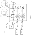
- FIG. 1B illustrates an exemplary embodiment of a dual-laser co-aligned/reflective Raman probe, wherein the laser sources 110, 120 are incorporated within the Raman probe housing 105.
- FIG. 1B are similar to the elements and operation discussed with regard to the dual-wavelength Raman probe shown in FIG. 1A . As both the components and the operation of the configuration shown in FIG. 1B are similar to the components and operation of the dual-laser Raman probe shown in FIG. 1A , the details of the components and operation of the configuration shown in FIG. 1B would be understood by those skilled in the art from a reading of the components and operation of FIG. 1A and, thus, further discussion of FIG. 1B is believed not needed.
- FIG. 1C illustrates an exemplary embodiment of a dual-laser co-aligned Raman/transmissive probe with a Raman probe wherein where the light outputted by external lasers sources 110, 120, are combined into a single optical beam 138 using wavelength beam combining with a dichroic mirror 135 and reflective mirror 136, as previously discussed.
- the second dichroic filter, 140 functions to direct the excitation light of the laser sources on to target object 160 through lens 150.
- Lens 150 further collects, and transmits to dichroic filter 140, the Raman wavelengths generated in response to an interaction of the excitation wavelengths.
- Dichroic filter 140 then transmits the collected Raman light, as optical beam 155, to filter 170.
- filter 170 operates to remove the light of laser sources 110 and 120 from being presented to slit 191 of spectrometer 190.
- FIG. 1C In this third exemplary embodiment of a dual-laser Raman probe, the remaining elements (components) and operation shown in FIG. 1C are similar to the elements and operation discussed with regard to the dual-wavelength Raman probe shown in FIG. 1A . As both the components and the operation of the configuration shown in FIG. 1C are similar to the components and operation of the dual-laser Raman probe shown in FIG. 1A , the details of the components and operation of the configuration shown in FIG. 1C would be understood by those skilled in the art from a reading of the components and operation of FIG. 1A and, thus, further discussion of FIG. 1C is believed not needed.
- FIG. 1D illustrates an exemplary embodiment of a dual-laser spatially-offset / transmissive Raman probe where the light outputted by two external laser sources 110, 120 is combined along a same optical path using wavelength beam combining with a dichroic mirror 135 and mirror 136 as previously discussed.
- the combined light 138 is then directed by mirror 152 through focusing lens 150 onto target object 160.
- Collection lens 151 collects the Raman light generated in response to the illumination of the target object 160 with the combined excitation (or illumination light) light 138 and directs the collected Raman light, i.e., light beam 155, to filter 170, which operates to remove the excitation wavelengths from the collected Raman light, as previously discussed.
- the remaining elements (components) and operation shown in FIG. 1D are similar to the elements (components) and operation discussed with regard to the dual-wavelength Raman probe shown in FIG. 1A .
- the details of the remaining components and operation of the configuration shown in FIG. 1D would be understood by those skilled in the art from a reading of the components and operation of FIG. 1A and, thus, further discussion of FIG. 1D is believed not needed.
- the invention further relates to a diagnostic system, comprising a spectrometer, said spectrometer comprising a known quantum efficiency, and a Raman probe device configured to provide Raman light wavelengths to said spectrometer, said Raman light wavelengths being generated in response to an excitation light illuminating a target object, wherein said excitation light comprises at least one of a first light comprising a first excitation wavelength, ⁇ p 2 and a second light comprising a second excitation wavelength, ⁇ p 1 , said first excitation wavelength selected based on a fluorescence generated by an interaction of the first excitation wavelength with said target object (this fluorescence can be regarded as at least one characteristic of said target object) and said second excitation wavelength determined based on a wavelength ⁇ QE at which a quantum efficiency of said spectrometer within the fingerprint region defined by the first excitation wavelength assumes a peak value and a Raman shifted peak of interest v POI for the target object. Therefore, the second excitation wavelength is based on said first
- the Raman shifted peak of interest ( ⁇ poi ) is a stretch peak emitted by the target object upon irradiation with the first laser light at the first excitation wavelength.
- the system further comprises a control unit that is adapted to determine the second excitation wavelength by executing the method according to the invention as described elsewhere herein.
- said Raman probe comprises a first lens configured to focus said first light and said second light onto said target object; and a filter configured to pass said Raman light wavelengths and to block said first wavelengths and said second wavelengths from passing to said spectrometer.
- said first lens is configured to collect said Raman light wavelengths and provide said collected Raman light wavelengths to said filter.
- the system as described above comprises a second lens, said second lens configured to collect said Raman light wavelengths, and to provide said Raman light wavelengths to said filter.
- the system comprises an optical device comprising: at least one optical fiber configured to receive said excitation light; and to direct said received excitation light to said target object; and a plurality of optical fibers configured to receive said Raman light wavelengths and to direct said received Raman light wavelengths to said second lens.
- the system comprises a mask, wherein said mask prevents selected ones of said plurality of optical fibers receiving said Raman light wavelengths from receiving said Raman light wavelengths.
- said optical device comprises: a plurality of optical fibers arranged in one of: a 1-dimensional array of optical fibers and a 2-dimensional array of optical fibers.
- said optical device comprises a plurality of optical fibers arranged annularly about a center optical fiber, wherein said center optical fiber is one of: said transmissive optical fiber and said receptive optical fiber.
- said at least one characteristic of the target object is associated with a fluorescence generated by said target object when illuminated by said first excitation wavelength.
- the first excitation wavelength is selected such as to minimize the impact of fluorescence on the Raman spectral signal.
- Said first light and said second light may be emitted concurrently.
- Said first excitation wavelength and said second excitation wavelength may be emitted sequentially.
- the system as described above comprises a first laser configured to generate said first light, wherein said first laser is one of: internal to said Raman probe and external to said Raman probe device; and/or a second laser configured to generate said second light, wherein said second laser is one of: internal to said Raman probe and external to said Raman probe device.
- said first lens is configured to collect said Raman wavelength and to present said collected Raman wavelength to said filter.
- the Raman probe as described above comprises a second lens, said second lens configured to collect said Raman wavelength and to present said collected Raman wavelength to said filter.
- the Raman probe as described above comprises a first laser source configured to emit said first excitation wavelength; and a second laser source configured to emit said second excitation wavelength, wherein at least one of said first laser source and said second laser source is external to said Raman probe.
- at least one of said first laser source and said second laser source may be internal to said Raman probe.
- said first excitation wavelength and said second excitation wavelength are emitted one of: concurrently and sequentially.
- the Raman probe as described above comprises an optic device comprising a plurality of optical fibers, wherein selected ones of said optical fibers receive said first excitation wavelength and said second excitation wavelength; and selected ones of said optical fibers receive said Raman light wavelengths.
- said plurality of optical fibers are arrange in one of a matrix configuration and an annular configuration.
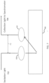
- FIG. 7 illustrates a block diagram of an exemplary embodiment of a distance based spatial-offset Raman probe configuration, wherein the spatial separation (or distance) 710 between the excitation light wavelengths 702 and the collected light wavelengths 704 allows for the detection of sub-surface regions of target object 160.
- the combined light 138 comprising first excitation wavelength 210 and second excitation wavelength 220 shall be referred to as excitation light 702 and the Raman light wavelengths shall be referred to as collected light wavelengths 704.
- the Raman light wavelengths 710 By increasing a distance 710 between the excitation light wavelengths 702 and collected light wavelengths 704 regions below a surface of target object 160 may be observed.
- FIG. 8 illustrates a block diagram of a second embodiment of a distance based spatially oriented Raman probe.
- this illustrated embodiment which is similar to the embodiment shown in FIG. 1D , further includes optical device 810, which is in optical communication with lenses 150 and 151.
- light (or excitation wavelengths) emitted by lens 150 are directed to optical device 810 through an optically clear material (e.g. optical fibers) and Raman light 704, generated in response to excitation light 702 illuminating target object 160, may be collected by optical device 810 and provided to collection lens 151 through a second set of optically clear material (e.g., optical fibers).
- an optically clear material e.g. optical fibers
- Raman light 704 generated in response to excitation light 702 illuminating target object 160
- optical device 810 may comprise an optical probe that may be used to scan target object 160 while emitting excitation wavelengths 702 and collecting Raman wavelengths 704.
- the tip of optical probe may include an optically clear material (e.g., plurality of optical fibers) that receive excitation wavelengths from lens 150 and a second, separate, optically clear material (e.g., optical fibers) that collect Raman light wavelengths and provide the collected Raman wavelengths to collection lens 151.
- optical device 810 may be a stationary device that includes a platform on to which target object may be placed or contained.
- Optical device 810 may include a plurality of optical fibers, for example, that receive excitation wavelengths 702 and a second plurality of optical fibers, for example, that collect Raman light wavelengths 704 and provide the collected Raman light wavelengths to collection lens 151.
- the first set of optical fibers and the second set of optical fibers may be orientated as shown in FIG. 7 , for example.
- the first set of optical fibers may be oriented such that the excitation wavelength 702 is projected onto target object 160 at an angle and the second set of optical fibers may be oriented at an angle with respect to target object 160.
- the first set of optical fibers (or clear material) may be positioned on one side of target object 160 and the second set of optical fibers may be positioned on a second side of target object 160.
- optical device 810 is shown external to housing 110, it would be recognized that optical device 810 may be internal to housing 110.
- FIG. 9A illustrates a first exemplary embodiment of optical device 810 wherein a first set of a plurality of optical fibers (or other optically clear material) 910, and a second set of optical fibers 920 are arranged in a 1-dimensional array.
- optic fibers 910 represent a transmissive device that may be used to provide excitation wavelengths or light 702 to target object 160 while optical fiber 920 represent a receptive device that may be used to collect Raman light or wavelengths704 and provide the collected light to collection lens 151 (see FIG. 8 ).
- Spatial distance 710 between the excitation wavelengths 702 and the Raman wavelength 704 may be varied, for example, by utilizing different ones of collection fibers 920.
- FIG. 9B illustrates a second example of optical device 810, which includes a two-dimensional array comprising a first and second sets of optical fibers 910, 920 are arranged in a matrix.
- excitation wavelengths or light 702 may be provided to target object 160 through fibers 910, while Raman light 704 may be collected through optical fibers 920.
- spatial distance 710 may be measured horizontally, vertically or diagonally with respect to the transmissive fibers and the receptive fibers.
- a mask may be utilized to limit the number of receptive devices receiving the Raman light wavelengths.
- the mask may be used for determining a minimum separation (or maximum separation distance).
- a mask (not shown) may be positioned between the second and fifth rows of receptive fiber optic cables, 920 to establish a minimum separation distance between the transmissive fiber optic cable 910 and the receiving fiber optic cables 920. Accordingly, the separation distance may be made variable.
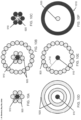
- FIGs. 10A-10F illustrate exemplary embodiment of optical devcie 810, wherein optical fibers 910, 920 are arranged in a circular or annular configuration.
- FIG. 10A illustrates an example of a center transmissive fiber 910 surrounded by a plurality of collection fibers 920.
- FIG. 10B illustrates an example of a center transmissive fiber 910 surrounded by two rows of a plurality of collection fibers 920.
- FIG. 10C illustrates an example of a plurality of transmissive fibers 910 centered around a center collection fiber 920.
- FIG. 10D illustrates an example of a center based transmissive fiber 910 surrounded by a ring of optically clear material 1020 for collecting the Raman light 704.
- FIG. 10E illustrates an example of a center based transmissive fiber 910 surrounded by a plurality of collection fibers 920.
- FIG. 10F illustrates an example of a center-based collection fiber 920 surrounded by a optically clear material 1010.
- physical separation 710 of excitation wavelength 702 from collected wavelength 704 may be achieved through the use of a central illumination (excitation) region and an annular collection region. In another embodiment, physical separation 710 of excitation wavelength 702 from collected wavelength704 may be achieved through the use an annular illumination (excitation) region and a central collection region. In another embodiment, the collection wavelength region may be physically moved or masked from the excitation wavelength region to allow for variable distance between the excitation wavelength illumination area and the collection light wavelength area.
- the excitation wavelength region and the collection wavelength region may be oriented on opposite sides of the target object, 160, in a so-called transmission configuration.
- the excitation wavelengths 702 may be directed toward target object 160 at an angle.
- the collected wavelengths 704 may be collected at an angle with respect to the target object 160.
- the combining of the excitation wavelengths discussed may be performed by any of a known number of known wavelength combining methods (e.g., wavelength beam combining with dichroic mirrors or geometric beam combining, see US 7,420,996 B2 ).
- the excitation lasers 110, 120 disclosed, herein may be operated simultaneously, concurrently or sequentially. Sequential operation eliminates spurious signals e.g., fluorescence, that may be generated when both laser sources were to be operated simultaneously. However, it would be understood that simultaneous or concurrent operation has been considered as well. Hence, when the operation of the sources is concurrent, the laser light of the two sources may be combined as in joining together to form a single light beam composed of two wavelengths. Whereas, when (e.g., wavelength beam, geometric beam combining (see US 7420,996 B2 , for example).
- the laser light of one source is considered “combined" with the non-presence of light from the second laser light source such that a single beam of a single wavelength is formed.
- Exemplary Raman pump wavelengths currently in use are 532 nm, 638 nm, 785nm, 830 nm, and 1064 nm.
- shorter wavelength pump wavelengths yield higher Raman scattered signals as the Raman intensity is proportional to ⁇ -4 .
- shorter pump wavelengths are more likely to give rise to fluorescence, which can overwhelm the Raman spectral features.
- the method of Raman concatenation offers the possibility of mitigating the negative impact of fluorescence with the shorter wavelength excitation source since fluorescence is wavelength dependent while the Raman signal is both proportional to the ⁇ -4 and shifts with respect to the excitation wavelength.
- the specific wavelength of the short or long wavelength laser source can be selected to mitigate any fluorescence resonance effects.
- Stokes spectra are typically more intense than are anti-Stokes spectra.
- the "fingerprint" region of the spectrum includes wavenumbers less than about 2000 cm -1 whereas the "stretch” region includes wavenumbers ranging from about 2000 cm -1 to 4000 cm -1 .
- FIG. 2 illustrates an example of the determination of fingerprint and stretch regions of a spectrum that may be excited by two separate wavelengths such that the two resultant Stokes signal spectra can be detected using a single detector array in a compact spectrometer.
- the two probe wavelengths designated as ⁇ p 1 210 and ⁇ p 2 220 excite the stretch and fingerprint regions of the Raman spectrum, respectively.
- the second excitation wavelength ⁇ p 1 is of a shorter wavelength than the first excitation wavelength ⁇ p 2 220.
- the illustrated fingerprint region 213 is shown as extending from Raman signal wavelengths ⁇ s 21 225 to ⁇ s 22 227, which are associated with the first excitation wavelength ⁇ p 2 220.
- Wavelengths ⁇ s 21 225 and ⁇ s 22 227 are determined from wavelength ⁇ p 2 220 by shifted values V 21 and V 22 , respectively, wherein shifted values V 21 and V 22 may be determined from equation 1, above.
- the illustrated Stretch region is shown as extending from Raman signal wavelengths ⁇ s 11 215 and ⁇ s 12 217, which are associated with the second excitation wavelength ⁇ p 1 210.
- Wavelengths ⁇ s 11 215 and ⁇ s 12 217 are determined from wavelength from ⁇ p 1 210 by shifted values V 11 and V 12 , respectively, wherein values V 11 and V 12 may be determined from equation 1, above.
- QE( ⁇ ) 230 of the spectrometer to be used for the collection and analysis of the Raman signals generated by the first and second excitation wavelengths.
- the generated Raman signals within both the stretch region and the fingerprint region may be captured by the detector element of a single spectrometer.
- the fingerprint region wavenumber range and Stretch region wavenumber range are approximately equal, i.e., ⁇ v 1 ⁇ ⁇ v 2 , resulting in ⁇ s 11 ⁇ ⁇ s 21 and ⁇ s 21 ⁇ s 22 .
- second excitation wavelength ⁇ p 1 210 and first excitation wavelength ⁇ p 2 220 may be selected to provide for the capture of both the fingerprint and Stretch region using a same detector array
- the selection of wavelengths ⁇ p 1 210 and ⁇ p 2 220 in accordance with the principles of the invention provides for the enhancement of the analytical performance of the spectrometer.
- FIG. 3 illustrates a flowchart 300 of an exemplary process for determining the wavelengths of a dual-wavelength Raman probe in accordance with the principles of the invention.
- a first excitation wavelength (i.e., ⁇ p 2 ) is selected.
- the first excitation wavelength is associated with the fingerprint region of the Raman signals reflected or scattered by the target object when illuminated by the first excitation wavelength.
- the first excitation wavelength, ⁇ p 2 is selected to be as short as possible to mitigate fluorescence of the Raman spectra generated by the inelastic scattering of the first excitation wavelength by the target object.
- first excitation wavelength, ⁇ p 2 is determined based on the Raman target sample 160 under investigation and its particular fluorescence characteristics when illuminated by the excitation wavelength.
- a first excitation wavelength, ⁇ p 2 for target classes of materials such as heavy petroleum (oil), biological materials, pharmaceutical materials and clear liquids may be selected as 1064 nm, 830 nm, 785 nm, and 532 nm, respectively.
- a wavelength such as 785 nm may be selected as the first excitation wavelength, wherein 785 nm is selected to minimize the fluorescence generated by the target object when illuminated by the first excitation wavelength.
- the desired range of the fingerprint region wavenumbers ( ⁇ v 2 ) is selected based on a desired spectral range and resolution of the spectrometer (e.g. 2000 cm -1 ) at step 320.
- the longest measured wavelength ⁇ s 22 may be determined from equation 4 above, as 931 nm.
- Inspection of the quantum efficiency spectrum associated with the spectrometer to be used in the collection and analysis of the Raman signals may then be performed to determine a peak wavelength of the spectrometer quantum efficiency response, QE( ⁇ ), in the determined fingerprint region (i.e., between wavelength ⁇ p 2 (which is approximately equal to ⁇ s 21 ) and ⁇ s 22 ( step 340).
- the quantum efficiency curve, QE( ⁇ ) provides a measure of the efficiency of the spectrometer to collect the Raman signals over a known wavelength band.
- the quantum efficiency response curve ( ⁇ QE ) within the range of the determined fingerprint region may be determined from current measurements or previous measurements of the response characteristics of the spectrometer.
- a peak (maximum) quantum efficiency ( ⁇ QE ) 235 of the quantum efficiency response curve 230 within the determined fingerprint region 223 may be determined.
- the peak quantum efficiency in this illustrated example may be determined to be 800 nm.
- the Raman shifted peak of interest (v poi ) may then be determined for the specific chemical compound under investigation (i.e., target object) at step 350.
- a Raman shifted peak of interest for a specific target object may be determined to be associated with a wavenumber of 3000 cm -1 .
- the second excitation wavelength, ( ⁇ p 1 ) may be determined based on the Raman shift peak of interest, which is associated with the specific target object, and the peak quantum efficiency of the spectrometer within the fingerprint region, which is defined by the selection of the first excitation wavelength.
- the selection of the second excitation wavelength in the manner disclosed in equation 5 provides for a coincidence of the Raman peak of interest wavelengths with the peak wavelength ( ⁇ QE ) of the spectrometer quantum efficiency within the fingerprint region.
- the selection of the second excitation wavelength is determined based of the peak quantum efficiency, as expressed in equation 5, and the most significant spectra performance may be achieved when the determined second excitation wavelength is coincident with the peak quantum efficiency, it would be recognized that a non-peak quantum efficiency value may similarly be utilized to determine the second excitation wavelength. It is, however, preferred that a wavelength ⁇ QE is determined at which the quantum efficiency within the range of a quantum efficiency curve QE( ⁇ ) assumes a peak value, associated with said spectrometer. That is, in accordance with the principles of the invention, the term “peak” as used with regard to the term “peak quantum efficiency” need not be the "peak” or maximum value as used in the ordinary and customary sense.
- the term "peak” is considered to be one of: the maximum value of the response spectra of the spectrometer and a range about the maximum value of the response spectra of the spectrometer.
- FIG. 3B illustrates an exemplary process for operating a dual-wavelength Raman probe in accordance with the principles of the invention.
- a first spectral Raman component generated by the excitation of the target object by a first excitation wavelength is captured, filtered, received, processed and stored as shown in steps 310, 365, 368, 371, 374, respectively. More specifically, a target object is illuminated by a first excitation wavelength (i.e., ⁇ p 2 ), which has been selected to minimize the fluorescence generated by the target object when illuminated by the first excitation wavelength.
- the Raman scattered light reflected or scattered by the target object is captured at step 365.
- the Raman scattered light is then filtered at step 368 and provided to the spectrometer at step 371.
- a spectral analysis performed on the reflected or scattered signals provided to the spectrometer are then stored at step 374.
- a second excitation wavelength (i.e., ⁇ p 1 ) is determined based on the first excitation wavelength and the quantum efficiency of the spectrometer within the fingerprint region determined based on the first excitation wavelength, as discussed above.
- an evaluation of the determined second excitation wavelength may be made with regard to wavelength performance of conventional laser devices in order to determine a suitability of using conventional lasers having known wavelength output.
- the wavelengths of one or more selected conventional lasers may be evaluated with regard to equation 6 to determine which of the more or more selected conventional lasers may be used in place of specially designed lasers that output a wavelength based on equation 5.
- a second Raman component generated by the excitation of the target object 160 by the determined second excitation wavelength is captured, filtered, received, processed, and stored as shown in steps 377, 381, 384, 387, 390, respectively.
- the target object 160 is illuminated by the second excitation wavelength at step 377.
- the scattered or reflected Raman wavelengths associated with the second excitation wavelength are captured (step 381) and filtered at step 384.
- the Raman wavelengths are provided to the spectrometer and at step 390, the results of a spectral analysis performed by the spectrometer are stored.
- the first and second Raman spectral component data are concatenated, or combined together, wherein the first Raman spectral component may be used to determine an identification of a compound of the target object 160, while the second Raman spectral component may be used to determine a concentration of the compound of the target object.
- the first and second Raman spectral may be processed independently to provide a more detailed analysis of the target object.
- the selection of the first and second excitation wavelengths in accordance with the principles of the invention provides for enhanced quantitative analysis as the Raman spectrum coincides (or substantially coincides) with a peak of the quantum efficiency of the spectrometer within the fingerprint region.
- the increased signal-to-noise ratio of the received Raman signals caused by the coincidence of the Raman signal with the peak of quantum efficiency of the spectrometer provides for an increase in the distinguishing features of the target object (or the component under analysis within the target object).
- the dual laser Raman probe described herein provides opportunities to monitor, for example, a pharmaceutical bioreactor (i.e., a sealed vessel in which bacteria are grown in an aqueous liquid).
- An H Stretch band may be used as a calibration standard against which CH and NH Stretch bands and be monitored.
- the CH and NH Stretch bands may be used to determine changes in proteins within a pharmaceutical bioreactor as proteins are generated by a bacteria and food (carbohydrates) are consumed.
- a concentration of an additive may be determined by calibration using the Raman signal of pure water.
- FIGs. 4A and 4B illustrate a typical silicon detector quantum efficiency curve ( FIG. 4A ) and a corresponding table ( FIG. 4B ) illustrating the expected quantum efficiency vs. wavenumber for a first Raman pump laser source for a 300 nm wavelength dispersion range.
- FIG. 4A which illustrates an exemplary quantum efficiency vs. wavenumber, and the efficiency associated with the wavelength shift associated with a 785 nm pump laser source
- a wavelength shift of the 785 nm excitation wavelength associated with a 200 cm -1 wavenumber provides for a quantum efficiency of 96 %
- a wavelength shift associated with a 3600 cm 1 wavenumber provides for an efficiency of 1%.
- an analysis of the Raman shifted wavelength associated with a 785 nm excitation wavelength at a 200 cm -1 is significantly better than an analysis of a Raman shifted wavelength, associated with a 785 nm excitation wavelength, at a 3600 cm -1 , as the performance of the spectrometer is significantly greater for the Raman shifted wavelength at 200 cm -1 .
- FIG. 4B tabulates the quantum efficiency for spectrometer efficiency associated with a 785 nm excitation wavelength for different wavelength shifts.
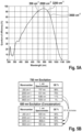
- FIGs. 5A and 5B illustrate the efficiency improvement and a corresponding table obtained for the selection of excitation wavelengths, in accordance with the principles of the invention.
- selection of the second excitation wavelength (e.g., 680 nm), based on the first wavelength and the spectral efficiency of the spectrometer, provides for a quantum efficiency of 90 percent at 200cm -1 whereas a wavelength shift associated with a 3600 cm -1 wavenumber provides a quantum efficiency of 82%.
- the selection of the second excitation wavelength in accordance with the principles of the invention provides significant improvement of the analysis of the Raman signals.
- selection of the dual excitation wavelengths through the matching of the peak of the quantum efficiency curve to a particular wavenumber band of interest provides for an enhancement in the signal processing capability of the spectrometer.
- a selection of a second excitation wavelength of 827.0676692 nm in accordance with the principles of the invention provides an improved, enhanced, signal-to-noise ratio in the Raman signal analyzed.
- the entire enhanced Stretch band may be used for additional data as input for chemometrics algorithms or as orthogonal data to validate of data from the fingerprint region.
- the Raman probe excitation wavelength selection method described, herein may have use in medical diagnostics as fats and proteins may be monitored using the CH and NH bands and water using the OH band water.
- Analysis of the CH and NH bands may help diagnose inflammation or other pathological conditions.
- the Raman probe excitation wavelength selection method described, herein, may have use in pharmaceutical process analytics for compound grown in water (H 2 O) as analysis of such compounds using near-infrared (NIR) spectroscopy is not effective.
- NIR near-infrared
- the Raman probe excitation wavelength selection method described, herein, may have use to analyze petrochemicals as CH bands are important and where water is generally a contaminant.
- this disclosure encompasses the use of a device as described herein in medical diagnostics and in analyses associated with petrochemical processing or bioreactors.
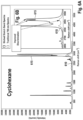
- Figures 6A and 6B illustrate examples of the enhancement of Raman signal processing using a wavelength laser pump source in the Stretch band region selected in accordance with the principles of the invention for cyclohexane.
- FIG. 6A illustrates the spectral analysis associated with the fingerprint region and the Stretch region associated with a target object including cyclohexane.
- FIG. 6B illustrates an expanded version of the Stretch region shown in FIG. 6A .
- FIG. 6A illustrates two Raman spectra 610 and 615, wherein spectra 610 is obtained using a 785 nm wavelength laser excitation signal and spectra 615 is obtained using a 785 first excitation wavelength of 785 nm and a second excitation wavelength of 680 nm, wherein the 680 nm wavelength is selected in accordance with the principles of the invention disclosed herein.
- Dual-wavelength Raman probe technology disclosed, herein enables new applications in the process automation market.
- the use of -H Stretch region vs. fingerprint region may provide for improved quantitative measurement of changes in concentration or predictive quantitation of concentration.
- the dual-wavelength Raman probe with the wavelength selection as presented, herein may be directly applicable to enhance the analysis of:
- a dual-wavelength Raman probe system comprising first and second excitation wavelengths impinge upon a target object and the reflected or scatted wavelength by the target object are collected and analyzed by a spectrometer.
- the excitation wavelengths are selected based on the target object and the quantum efficiency (or within a known range) of the spectrometer in order to improve the signal to noise ratio of the Raman signals by having the Raman signals substantially coincide with the peak quantum efficiency of the spectrometer. Collection of the Raman signals substantially coincident with the peak quantum efficiency of the spectrometer provides for an improved signal to noise ratio of the Raman signal.
- a wavelength emitted by the laser source or operated on by the Raman and Rayleigh scattering
- a wavelength is a term of art and refers to a wavelength or a band of wavelengths around a nominal desired wavelength.
- the invention has been described with reference to specific embodiments.
- One of ordinary skill in the art appreciates that various modifications and changes can be made without departing from the scope of the invention as set forth in the claims. Accordingly, the specification is to be regarded in an illustrative manner, rather than with a restrictive view.
- wavelength is sometimes used as an abbreviation for the expression "light of a (certain) wavelength”.
- light of a (certain) wavelength The skilled person will be aware, that in these cases, the expressions are interchangeable.
- wavenumbers (v, usually given in cm -1 ) and wavelengths ( ⁇ , usually given in nm) must be converted into the same dimensions for the purpose of calculations.
- the terms “comprises”, “comprising”, “includes”, “including”, “has”, “having”, or any other variation thereof, are intended to cover non-exclusive inclusions.
- a process, method, article or apparatus that comprises a list of elements is not necessarily limited to only those elements but may include other elements not expressly listed or inherent to such process, method, article, or apparatus.
- the term “or' refers to an inclusive “or” and not to an exclusive “or”. For example, a condition A or B is satisfied by any one of the following: A is true (or present) and B is false (or not present); A is false (or not present) and B is true (or present); and both A and B are true (or present).
Landscapes
- Physics & Mathematics (AREA)
- Spectroscopy & Molecular Physics (AREA)
- General Physics & Mathematics (AREA)
- Health & Medical Sciences (AREA)
- Nuclear Medicine, Radiotherapy & Molecular Imaging (AREA)
- Life Sciences & Earth Sciences (AREA)
- Chemical & Material Sciences (AREA)
- Analytical Chemistry (AREA)
- Biochemistry (AREA)
- General Health & Medical Sciences (AREA)
- Immunology (AREA)
- Pathology (AREA)
- Investigating, Analyzing Materials By Fluorescence Or Luminescence (AREA)
Description
- This invention relates to the field of spectroscopy and more particularly to a compact Raman spectroscopy system and method for providing enhanced quantitative analysis for process control.
- This invention disclosed, herein, is related to that subject matter recited and taught in
US 10,359,313 B1 - Raman spectroscopy is a well-known technique that can be used to observe vibrational, rotational and other low-frequency modes in molecules. Raman scattering is an inelastic process whereby monochromatic light typically provided by a laser interacts with molecular vibrations, phonons or other excitations resulting in the energy of the laser photons being shifted up or down. Due to conservation of energy the emitted photon gains or loses energy equal to energy of the vibrational state.
- Many Raman measurements suffer from fluorescence, which forces usage of longer wavelength (lower energy) excitation lasers to mitigate against the fluorescent signal overwhelming the Raman signal, thereby making the latter impossible to extract. Usage of longer excitation wavelengths facilitates extraction of Raman signals from fluorescent samples but at a cost of reduced sensitivity in the silicon CCD detectors that capture spectrometer signals.
- Known Raman probes that capture a Raman spectra covering the entire range of wavenumbers from 0 cm-1 to 4000 cm-1 can be accomplished by use of:
- (1) a single laser source with a large spectrometer incorporating long sensors to capture photons at all relevant wavenumbers with sufficient resolution;
- (2) a single laser source with multiple spectrometers / detectors that each cover a different wavelength range (e.g. silicon and InGaAs);
- (3) multiple laser sources with a single spectrometer, or
- (4) multiple laser sources with separate spectrometers configured to capture multiple Raman spectra each covering a smaller range of wavenumbers.
- Examples of the use of multiple laser techniques are disclosed by:
- "Novel Pressure-Induced Molecular Transformations Probed by In Situ Vibrational Spectroscopy", Yang Song,
- "Applications of Molecular Spectroscopy to Current Research in the Chemical and Biological Sciences", Mark T. Stauffer (ed.), October 5, 2016. Chapter 8,
- "Spatially Compressed Dual-Wavelength Excitation Raman Spectrometer," J.B. Cooper, S. Marshall, R. Jones, M. Abdelkader, and K.L. Wise, Applied Optics, 53, 3333 (2014);
- "Dual Wavelength Raman Spectroscopy: Improved Compactness and Spectral Resolution," J. Kiefer, https://www.americanpharmaceuticalreview.com/Featured-Articles/354604-Dual-Wavelength-Raman-Spectroscopy-Improved-Compactness-and-Spectral-Resolution/ posted 16-Oct-2018.
- "Raman Fusion Spectroscopy: Multiwavelength Excitation for Compact Devices, J. Kiefer, SciX 2019. (13-18 Oct 2019).
- "Apparatus and Method for Composite Raman Multispectral Spectrometry", BRUNEEL, Jean-Luc, BUFFETEAU, Thierry, DAUGEY, Nicolas, RODRIGUEZ, Vincent,
WO 2019/220047 A1 (2019 ) and -
US 10,359,313 B1 - Each of the referred-to references focuses on capture of multiple Raman spectra using a dual-laser configuration. However, the references fail to disclose the means for selecting wavelengths used in the spectral analysis based on the material selected and the characteristics of the spectrometer utilized. Hence, there is a need in the industry for a compact Raman probe and spectrometer system that provides for improved quantitative analysis using two or more probe laser wavelengths and a method for selecting the laser probe wavelengths to enhance a quantitative analysis of a target material under investigation for different applications.
- The Raman spectral concatenation concept described herein allows use of a single, relatively compact spectrometer to collect both fingerprint and stretch Raman spectra (i.e., collected Raman wavelengths) and a method for selecting the laser source wavelengths to provide for enhanced quantitative analysis of target material under investigation. In accordance with the principles of the invention, the fingerprint spectrum is captured using one excitation wavelength, whereas the stretch spectrum is captured using a second wavelength selected based on a quantum efficiency of the spectrometer and the first wavelength. The selection of one or more of the laser source wavelengths in the manner disclosed, herein, provides for enhanced signal to noise ratio so as to enhance the performance of a quantitative analysis of a target material under investigation.
- A compact dual-wavelength Raman probe configured to provide two or more separate laser wavelengths selected in a manner to provide enhanced quantitative analysis of material under investigation is disclosed.
- Described herein are embodiments in which two laser sources may be integrated within the housing of (or internal to) a Raman probe and or external to the housing of a Raman probe.
- Described herein are embodiments in which light output emitted by two lasers sources may be combined in a common optical path, wherein the emitted light may be combined using either wavelength beam combining with dichroic mirrors or geometric beam combining.
- Described herein are embodiments of a Raman probe utilizing coalignment of the excitation and collection light utilizing a same optical axis.
- Described herein are embodiment of a Raman probe utilizing a spatially offset of the excitation and collection lights utilizing separate optical paths.
- Described herein are embodiments of a method for selecting the wavelengths of light emitted by two laser sources in a Raman probe wherein the wavelengths of the laser sources or probes are selected in a manner based, in part, on the quantum efficiency of a spectrometer used for the analysis of the light reflected by the target material.
- In accordance with the principles of the invention, the wavelengths of the probe lasers used in a dual-wavelength Raman probe are selected based on the quantum efficiency of a spectrometer comprising a single detector array (silicon, InGaAs, or any other detector array) within the spectrometer. The quantum efficiency of a detector is a measure of the ratio of collected to incident photons versus wavelength and is a common characteristic of spectrometers supplied by manufacturers.
- The invention is directed to a method for determining a first excitation wavelength and a second excitation wavelength for use in a dual laser spectrometer system. Such system comprises a first laser source configured to emit a first excitation wavelength and a second laser source configured to emit a second excitation wavelength; and a spectrometer configured to receive a first Raman signal and a second Raman signal, wherein said first Raman signal is associated with said first excitation wavelength and said second Raman signal is associated with said second excitation wavelength. Said method comprises
- selecting said first excitation wavelength based on at least one characteristic of a target object, wherein said at least one characteristic is associated with a fluorescence generated by an interaction of the first excitation wavelength with said target object;
- determining a fingerprint region, of the first Raman signal associated with said first excitation wavelength;
- determining a wavelength λQE at which a quantum efficiency of the spectrometer within the fingerprint region assumes a peak value, (which can be done, for example, by determining a peak quantum efficiency value (λQE) within the determined range, preferably the fingerprint region, of a quantum efficiency curve, QE(λ), associated with said spectrometer, preferably determining a wavelength (λQE) at which the quantum efficiency within the range of a quantum efficiency curve QE(λ) assumes a peak value, associated with said spectrometer);
- determining a Raman shifted peak of interest (vpo1) for the target object; and
- determining said second excitation wavelength based on the peak quantum efficiency value wavelength λQE and the Raman shifted peak of interest νpoi.
- Said second excitation wavelength λp1 is determined as:

- Described herein is further a diagnostic system, comprising, optionally, a spectrometer, said spectrometer having a known quantum efficiency; and a Raman probe device configured to provide Raman light wavelengths to the spectrometer, said Raman light wavelengths being generated in response to an excitation light illuminating a target object,
wherein said excitation light comprises at least one of a first light comprising a first wavelength, λp 2, and a second light comprising a second wavelength, λp 1, said first excitation wavelength selected based on at least one characteristic of said target object, and said second excitation wavelength determined based on said first excitation wavelength and a wavelength associated with substantially a peak value of said known quantum efficiency. - The diagnostic system may comprise a control unit adapted to determine the second excitation wavelength, preferably adapted to execute the method substantially as described above.
- Described herein is a computer programm comprising instructions to cause the system as described above to determine the second excitation wavelength, preferably by executing the method substantially as described above.
- The probe laser wavelengths are determined for different applications based on the quantum efficiency of the spectrometer and the material in a target object such that a desired Raman spectra is substantially coincident to a peak of the detector quantum efficiency and, hence, achieving higher signal to noise ratio.
- The selection of Raman excitation wavelengths based on the quantum efficiency of the spectrometer allows shifting of both the fingerprint and stretch regions of the Raman spectrum to wavelengths at which silicon detectors (or similar detectors) have relatively high quantum efficiency.
- Raman spectra of each of the two laser sources may be captured separately and subsequently concatenated, or stitched together, to provide a single spectral scan encompassing the entire range of data, including the fingerprint and stretch regions, wherein the signal-to-noise ratio of the Raman signal in the stretch region is enhanced.
- Analyzing each data set independently is also possible, while collecting the spectra from both excitation wavelengths simultaneously may also be possible.
- The compact dual-wavelength Raman probe, disclosed herein, may include optics to configure the output beam of each laser source to have a circular, an elliptical or an elongated cross-section, approximating a shape of a circular or a shape of the elongated emission region of the laser near-field.
- The light generated by the laser sources is emitted toward a target object or material under investigation and the resultant scattered signal light is transmitted by the compact Raman probe via an optical beam that may also have a corresponding elliptical cross-section. The excitation and collection paths may be co-linear (i.e., co-aligned) or separate (e.g., spatially-offset (see USPPA 20080076985) or transmission geometry (see
USP 8085396 )). An optical fiber incorporating a core having dimensions approximating those of the returned scattered light beam, transmits the returned scattered light to the entrance aperture of a spectrometer. - The dual-wavelength Raman probe disclosed herein, the dual-wavelength Raman probe may include external cavity lasers (ECLs) that may be integrated into the probe as wavelength-stabilized laser sources. See, for example,
US 9,059,555 B2 - A distributed Bragg reflector (DBR) or distributed feedback (DFB) lasers may comprise a wavelength-stabilized laser source that may be integrally incorporated into the Raman probe or may be retained external to the Raman probe.
- The light emitted by a laser may be used as the pump source for a non-linear optical (NLO) conversion to produce a different wavelength, e.g., by second-harmonic generation (SHG), third-harmonic generation (THG), or any other non-linear optical process.
- In the compact dual wavelength Raman probe, the selection of a second wavelength is based, in part, on a first wavelength and a spectral efficiency of the spectrometer used to collect the Raman signal, as disclosed elsewhere herein.
- For a better understanding of exemplary embodiments and to show how the same may be carried into effect, reference is made to the accompanying drawings. It is stressed that the particulars shown are by way of example only and for purposes of illustrative discussion of the preferred embodiments of the present disclosure and are presented in the cause of providing what is believed to be the most useful and readily understood description of the invention. In this regard, no attempt is made to show structural details of the invention in more detail than is necessary for a fundamental understanding of the invention. The description taken with the drawings making apparent to those skilled in the art how the several forms of the invention may be embodied in practice. In the accompanying drawings:
-
FIG. 1A illustrates a block diagram of an exemplary embodiment of a dual-wavelength co-aligned/reflective Raman probe using external laser sources. -
FIG 1B . illustrates a block diagram of an exemplary embodiment of a dual-wavelength co-aligned/reflective Raman probe using internal laser sources. -
FIG. 1C illustrates a block diagram of an exemplary embodiment of a dual-wavelength co-aligned/transmissive Raman probe using external laser sources. -
FIG 1D illustrates a block diagram of an exemplary embodiment of a dual-wavelength spatially-offset/transmissive Raman probe. -
FIG. 2 illustrates a graphical representation for the selection of laser wavelengths in a dual-wavelength Raman probe in accordance with the principles of the invention. -
FIG. 3A illustrates a flow chart of an exemplary process for selecting laser wavelengths in a dual-wavelength Raman probe, in accordance with the principles of the invention. -
FIG. 3B illustrates a flow chart of an exemplary process associated with a dual-wavelength Raman probe in accordance with the principles of the invention. -
FIGs. 4A and 4B illustrate an exemplary quantum efficiency response of a silicon detector linear array with 300 nm dispersion for two different Raman laser pump sources. -
FIGs. 5A and 5B illustrate a second exemplary quantum efficiency response of a silicon detector linear array with 300 nm dispersion for two different Raman laser pump sources. -
FIG. 6A illustrates an exemplary spectral analysis of a target material containing cyclohexane, with and without the selection of excitation wavelengths in accordance with the principles of the invention. - FIG. 6B illustrates an expanded section of the spectral analysis shown in
FIG. 6A . -
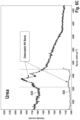
FIG. 6C illustrates an exemplary spectral analysis of a target material containing Urea. -
FIG. 6D illustrates an exemplary spectral analysis of a target material containing water. -
FIG. 7 illustrates a block diagram of an exemplary embodiment of a distance based spatial-offset Raman probe configuration. -
FIG. 8 illustrates a block diagram of another embodiment of a spatially offset Raman probe. -
FIGs. 9A and 9B illustrate exemplary 1-dimensional and 2-dimensional linear arrays for the transmission of excitation wavelengths and collection of Raman wavelengths -
FIGs. 10A-10F illustrate exemplary circular or annular configurations for the transmission of excitation wavelengths and collection of Raman wavelengths. - It is to be understood that the figures and descriptions of the present invention described herein have been simplified to illustrate the elements that are relevant for a clear understanding of the present invention, while eliminating, for purposes of clarity many other elements. However, because these omitted elements are well-known in the art, and because they do not facilitate a better understanding of the present invention, a discussion of such elements is not provided herein. The scope of the invention is defined by the appended claims.
-
FIG. 1A illustrates a block diagram of an exemplary embodiment of a compact dual-wavelength co-aligned/reflective Raman probe configuration where the light outputted by corresponding ones of the illustrated two laser sources are combined along a same optical path using wavelength beam combining with a dichroic mirror, which is similar to the configuration shown in, and disclosed with regard toFIG. 5 ofUS 10,359,313 B1 - In this exemplary embodiment, a dual
wavelength Raman probe 100 includes ahousing 105 and two externallight sources light sources optical fibers housing 105. Thelasers Optical couples - The
laser sources laser sources - One class of lasers that may be used as a wavelength-stabilized laser source is an external cavity laser. See, for example,
US 9,059,555 B2 US 9,577,409 B1 Sources -
Laser sources - The compact dual-
wavelength Raman probe 100 further includesoptics laser sources FIG. 1A , arelenses laser 110 to form, for example, a beam cross-section suitable for exciting Raman signal (or wavelengths) by a target of interest, 160, andcorresponding components laser 120. Narrow-band filters lasers - Collimated light beams 131 and 132 are combined into a single collimated
beam 138 by use of a firstdichroic mirror 135 and reflectingmirror 136, whereinmirror 136 redirectslight beam 132 towards firstdichroic mirror 135. Firstdichroic mirror 135 further passeslight beam 132 and redirectslight beam 131 to form collimatedbeam 138. - A single short pass filter (not shown). with cut-off wavelength designed to pass the wavelengths emitted by the
first laser 110 and thesecond laser 120 but blocks wavelengths beyond the longer of the two wavelengths (i.e.,light beams 131, 132) may be placed after the light beams 131, 132 are combined into collimated beam oflight 138. - The probe (excitation, illumination)
light beam 138 is transmitted through a second short-passdichroic mirror 140, with transmission characteristics schematically depicted ininset 141, tolens 150 which focuses the combined light, comprising the wavelengths emitted by thefirst laser 110 and thesecond laser 120 onto thetarget object 160 alonglight path 145. - Light scattered from the
target object 160 will include Raman, Rayleigh and fluorescent components, which may be collected bylens 150 and directed back towards the seconddichroic mirror 140 throughlight path 145. In this illustrated case,dichroic mirror 140 is configured to reflect the longer Stokes-shifted Raman photons into collimatedbeam 155. Light at wavelengths longer than the filter cutoff, including at the two excitation wavelengths, will, to a great extent, pass through seconddichroic mirror 140 and be largely eliminated frombeam 155. - Additional optical elements (not shown) may be included in the light path of
light beam 138 to shapelight beam 138. For example,light beam 138 may be shaped into a circular beam such that the light beam 138 (i.e., combined first excitation wavelength and second excitation wavelength) forms an annular region on saidtarget object 160. The optical elements may be configured to adjust a diameter of the annular region projected onto the target object. The additional optical elements (not shown) may be included the light path oflight beam 138 to shapelight beam 138 into an elliptical or elongated shape. - The spatial extent of the excitation light on the
target 160 may be sufficiently long to give rise to off-axis scattered light, which may result in the reflection of a range of wavelengths - including those that would be preferentially excluded - by the seconddichroic mirror 140 intobeam 155. The design ofdichroic mirror 140 preferably is such that unwanted light is eliminated as much as is possible. -
Dichroic mirror 140 may be an edge filter that is designed to direct wavelengths of the Raman scattered light towardspectrometer 190, along a single optical fiber or axis (i.e., co-aligned), while substantially removing other light near the pump wavelengths. - In an embodiment of the invention disclosed in which the Stokes signal wavelength is to be detected, the
dichroic mirror 140 is a short-pass filter that reflects wavelengths longer than that of the pump wavelength and substantially removes wavelengths at and shorter than the pump wavelengths fromoptical beam 155, as shown. - In an embodiment of the invention disclosed, in which anti-Stokes signals are to be detected, the
dichroic mirror 140 is a long-pass filter that reflects wavelengths shorter than that of the pump wavelength and substantially removes wavelengths at and longer than the pump wavelengths fromoptical beam 155. -
Dichroic mirror 140 is typically used at a 45□ angle of incidence and, in the embodiment shown inFIG. 1A , transmits light from thelaser sources target 160 under investigation. Exemplary dichroic mirror are Semrock's RAZOREDGE beamsplitters. RAZOREDGE is a registered Trademark of IDEX Health & Science LLC, Rohnert Park, California. - For detection of Stokes signals, long-pass
dichroic filter 170 is designed to transmit wavelengths longer than its cutoff wavelength, as shown ininset 171.Lens 180 focuses the filtered light onto the entrance facet ofoptical fiber 185, which transmits the light to slit 191 of acompact spectrometer 190. - The
filter 170 may be one of: a dichroic filter, a volume holographic grating filter, and a fiber Bragg grating filter, used in combination with focusing and collection optics or any filter that provides the required wavelength-dependent blocking and transmitting capabilities. Exemplary filters include STOPLINE□ single notch filters and RAZOREDGE® ultra-steep long-pass edge filters for Stokes detection and ultra-steep short-pass edge filter for anti-Stokes detection. STOPLINE and RAZOREDGE are registered Trademarks of IDEX Health & Science LLC, Rohnert Park, California. -
Spectrometer 190 is designed to diffract light input throughslit 191 to a linear silicon detector array (not shown). The range of light diffracted onto the array is limited by the design of the spectrometer's diffraction grating and linear extent of the detector array as is well-known in the art. Accordingly, a spectrometer's grating and detector may be configured so that the detector receives a limited range of wavelengths, e.g., approximately 791 nm to 934 nm for Stokes signals. An exemplary 2048-element linear detector may have a resolution of approximately 1 cm-1 (i.e., 1 wavenumber, wherein wavenumber is a term of art within the optical field) in both the fingerprint and stretch regions of the spectrum if detected separately. - In another embodiment of the invention, the light from
lasers FIG. 1A may be combined onto a single fiber (not shown) before being presented todichroic mirror 140. The elements generating and combining the light fromlasers body 105 and instead may be combined outside of thebody 105 by means of either geometric or dichroic combination and subsequently combined into a single fiber before being presented to thedichroic mirror 140. -
FIG. 1B illustrates an exemplary embodiment of a dual-laser co-aligned/reflective Raman probe, wherein thelaser sources Raman probe housing 105. In this second exemplary embodiment of a dual-laser Raman probe, the elements (components) and operation of the Raman probe shown in -
FIG. 1B are similar to the elements and operation discussed with regard to the dual-wavelength Raman probe shown inFIG. 1A . As both the components and the operation of the configuration shown inFIG. 1B are similar to the components and operation of the dual-laser Raman probe shown inFIG. 1A , the details of the components and operation of the configuration shown inFIG. 1B would be understood by those skilled in the art from a reading of the components and operation ofFIG. 1A and, thus, further discussion ofFIG. 1B is believed not needed. -
FIG. 1C illustrates an exemplary embodiment of a dual-laser co-aligned Raman/transmissive probe with a Raman probe wherein where the light outputted byexternal lasers sources optical beam 138 using wavelength beam combining with adichroic mirror 135 andreflective mirror 136, as previously discussed. In this third exemplary embodiment, the second dichroic filter, 140, functions to direct the excitation light of the laser sources on to targetobject 160 throughlens 150.Lens 150 further collects, and transmits todichroic filter 140, the Raman wavelengths generated in response to an interaction of the excitation wavelengths.Dichroic filter 140 then transmits the collected Raman light, asoptical beam 155, to filter 170. In this case,filter 170, operates to remove the light oflaser sources slit 191 ofspectrometer 190. - In this third exemplary embodiment of a dual-laser Raman probe, the remaining elements (components) and operation shown in
FIG. 1C are similar to the elements and operation discussed with regard to the dual-wavelength Raman probe shown inFIG. 1A . As both the components and the operation of the configuration shown inFIG. 1C are similar to the components and operation of the dual-laser Raman probe shown inFIG. 1A , the details of the components and operation of the configuration shown inFIG. 1C would be understood by those skilled in the art from a reading of the components and operation ofFIG. 1A and, thus, further discussion ofFIG. 1C is believed not needed. -
FIG. 1D illustrates an exemplary embodiment of a dual-laser spatially-offset / transmissive Raman probe where the light outputted by twoexternal laser sources dichroic mirror 135 andmirror 136 as previously discussed. The combinedlight 138 is then directed bymirror 152 through focusinglens 150 ontotarget object 160.Collection lens 151 collects the Raman light generated in response to the illumination of thetarget object 160 with the combined excitation (or illumination light)light 138 and directs the collected Raman light, i.e.,light beam 155, to filter 170, which operates to remove the excitation wavelengths from the collected Raman light, as previously discussed. - In this fourth exemplary embodiment of a dual-laser Raman probe, the remaining elements (components) and operation shown in
FIG. 1D are similar to the elements (components) and operation discussed with regard to the dual-wavelength Raman probe shown inFIG. 1A . As both the remaining components and the operation of the configuration shown inFIG. 1D are similar to the remaining components and operation of the dual-laser Raman probe shown inFIG. 1A , the details of the remaining components and operation of the configuration shown inFIG. 1D would be understood by those skilled in the art from a reading of the components and operation ofFIG. 1A and, thus, further discussion ofFIG. 1D is believed not needed. - The invention further relates to a diagnostic system, comprising a spectrometer, said spectrometer comprising a known quantum efficiency, and a Raman probe device configured to provide Raman light wavelengths to said spectrometer, said Raman light wavelengths being generated in response to an excitation light illuminating a target object, wherein said excitation light comprises at least one of a first light comprising a first excitation wavelength, λp 2 and a second light comprising a second excitation wavelength, λp 1, said first excitation wavelength selected based on a fluorescence generated by an interaction of the first excitation wavelength with said target object (this fluorescence can be regarded as at least one characteristic of said target object) and said second excitation wavelength determined based on a wavelength λQE at which a quantum efficiency of said spectrometer within the fingerprint region defined by the first excitation wavelength assumes a peak value and a Raman shifted peak of interest vPOI for the target object. Therefore, the second excitation wavelength is based on said first excitation wavelength and a wavelength associated with substantially a peak value of said known quantum efficiency.
- Said second excitation wavelength is determined as:

- The system further comprises a control unit that is adapted to determine the second excitation wavelength by executing the method according to the invention as described elsewhere herein.
- In a preferred embodiment, within the system as described above said Raman probe comprises a first lens configured to focus said first light and said second light onto said target object; and a filter configured to pass said Raman light wavelengths and to block said first wavelengths and said second wavelengths from passing to said spectrometer.
- In a preferred embodiment, within the system as described above, said first lens is configured to collect said Raman light wavelengths and provide said collected Raman light wavelengths to said filter.
- In a preferred embodiment, the system as described above comprises a second lens, said second lens configured to collect said Raman light wavelengths, and to provide said Raman light wavelengths to said filter.
- In a preferred embodiment, the system comprises an optical device comprising: at least one optical fiber configured to receive said excitation light; and to direct said received excitation light to said target object; and a plurality of optical fibers configured to receive said Raman light wavelengths and to direct said received Raman light wavelengths to said second lens.
- In a preferred embodiment, the system comprises a mask, wherein said mask prevents selected ones of said plurality of optical fibers receiving said Raman light wavelengths from receiving said Raman light wavelengths.
- In a preferred embodiment, within the system as described above, said optical device comprises: a plurality of optical fibers arranged in one of: a 1-dimensional array of optical fibers and a 2-dimensional array of optical fibers.
- In a preferred embodiment, within the system as described above, said optical device comprises a plurality of optical fibers arranged annularly about a center optical fiber, wherein said center optical fiber is one of: said transmissive optical fiber and said receptive optical fiber.
- Within the system as described above, said at least one characteristic of the target object is associated with a fluorescence generated by said target object when illuminated by said first excitation wavelength. The first excitation wavelength is selected such as to minimize the impact of fluorescence on the Raman spectral signal.
- Said first light and said second light may be emitted concurrently. Said first excitation wavelength and said second excitation wavelength may be emitted sequentially.
- In a preferred embodiment, the system as described above comprises a first laser configured to generate said first light, wherein said first laser is one of: internal to said Raman probe and external to said Raman probe device; and/or a second laser configured to generate said second light, wherein said second laser is one of: internal to said Raman probe and external to said Raman probe device.
- This disclosure further relates to Raman probe device comprising a first lens, said first lens configured to receive at least one of: a first excitation wavelength λp 2, said first excitation wavelength determined based on at least one characteristic of a target object, and a second excitation wavelength λp 1; and said first lens configured to focus said at least one of said first excitation wavelength and said second excitation wavelength onto said target object, wherein a Raman wavelength is generated in response to said target object being illuminated by a corresponding one of at least one of said first excitation wavelength and said second excitation wavelength; and wherein the Raman probe device further comprises a filter, said filter configured to pass said Raman wavelength generated in response to said target object being illuminated by a corresponding one of at least one of said first excitation wavelength and said second excitation wavelength, to a spectrometer; and wherein said spectrometer comprises a known quantum efficiency and said second excitation wavelength is determined as: λp 1 = 1 / [vpoi + 1/λQE] ; wherein λQE is a wavelength associated with a peak of said quantum efficiency within a range defined by the first excitation wavelength; and vpoi is the Raman shifted peak of interest for the target object.
- In a preferred embodiment of the Raman probe as described above, said first lens is configured to collect said Raman wavelength and to present said collected Raman wavelength to said filter.
- In a preferred embodiment, the Raman probe as described above comprises a second lens, said second lens configured to collect said Raman wavelength and to present said collected Raman wavelength to said filter.
- In a preferred embodiment, the Raman probe as described above comprises a first laser source configured to emit said first excitation wavelength; and a second laser source configured to emit said second excitation wavelength, wherein at least one of said first laser source and said second laser source is external to said Raman probe. Alternatively, at least one of said first laser source and said second laser source may be internal to said Raman probe.
- In a preferred embodiment of the Raman probe as described above, said first excitation wavelength and said second excitation wavelength are emitted one of: concurrently and sequentially.
- In a preferred embodiment, the Raman probe as described above comprises an optic device comprising a plurality of optical fibers, wherein selected ones of said optical fibers receive said first excitation wavelength and said second excitation wavelength; and selected ones of said optical fibers receive said Raman light wavelengths.
- In a preferred embodiment of the Raman probe as described above, said plurality of optical fibers are arrange in one of a matrix configuration and an annular configuration.
-
FIG. 7 illustrates a block diagram of an exemplary embodiment of a distance based spatial-offset Raman probe configuration, wherein the spatial separation (or distance) 710 between theexcitation light wavelengths 702 and the collected light wavelengths 704 allows for the detection of sub-surface regions oftarget object 160. Hereafter, the combinedlight 138 comprisingfirst excitation wavelength 210 andsecond excitation wavelength 220 shall be referred to asexcitation light 702 and the Raman light wavelengths shall be referred to as collected light wavelengths 704. By increasing adistance 710 between theexcitation light wavelengths 702 and collected light wavelengths 704 regions below a surface oftarget object 160 may be observed. -
FIG. 8 illustrates a block diagram of a second embodiment of a distance based spatially oriented Raman probe. In this illustrated embodiment, which is similar to the embodiment shown inFIG. 1D , further includesoptical device 810, which is in optical communication withlenses lens 150 are directed tooptical device 810 through an optically clear material (e.g. optical fibers) and Raman light 704, generated in response toexcitation light 702 illuminatingtarget object 160, may be collected byoptical device 810 and provided tocollection lens 151 through a second set of optically clear material (e.g., optical fibers). - For example,
optical device 810 may comprise an optical probe that may be used to scantarget object 160 while emittingexcitation wavelengths 702 and collecting Raman wavelengths 704. The tip of optical probe may include an optically clear material (e.g., plurality of optical fibers) that receive excitation wavelengths fromlens 150 and a second, separate, optically clear material (e.g., optical fibers) that collect Raman light wavelengths and provide the collected Raman wavelengths tocollection lens 151. Alternatively,optical device 810 may be a stationary device that includes a platform on to which target object may be placed or contained.Optical device 810 may include a plurality of optical fibers, for example, that receiveexcitation wavelengths 702 and a second plurality of optical fibers, for example, that collect Raman light wavelengths 704 and provide the collected Raman light wavelengths tocollection lens 151. In addition, the first set of optical fibers and the second set of optical fibers may be orientated as shown inFIG. 7 , for example. In another embodiment, the first set of optical fibers may be oriented such that theexcitation wavelength 702 is projected ontotarget object 160 at an angle and the second set of optical fibers may be oriented at an angle with respect to targetobject 160. In still another embodiment, the first set of optical fibers (or clear material) may be positioned on one side oftarget object 160 and the second set of optical fibers may be positioned on a second side oftarget object 160. - Although
optical device 810 is shown external tohousing 110, it would be recognized thatoptical device 810 may be internal tohousing 110. -
FIG. 9A illustrates a first exemplary embodiment ofoptical device 810 wherein a first set of a plurality of optical fibers (or other optically clear material) 910, and a second set ofoptical fibers 920 are arranged in a 1-dimensional array. In this exemplary embodiment,optic fibers 910 represent a transmissive device that may be used to provide excitation wavelengths or light 702 to targetobject 160 whileoptical fiber 920 represent a receptive device that may be used to collect Raman light or wavelengths704 and provide the collected light to collection lens 151 (seeFIG. 8 ). -
Spatial distance 710 between theexcitation wavelengths 702 and the Raman wavelength 704 may be varied, for example, by utilizing different ones ofcollection fibers 920. -
FIG. 9B illustrates a second example ofoptical device 810, which includes a two-dimensional array comprising a first and second sets ofoptical fibers - As with the arrangement shown in
FIG. 9A , excitation wavelengths or light 702 may be provided to targetobject 160 throughfibers 910, while Raman light 704 may be collected throughoptical fibers 920. - In this illustrated embodiment,
spatial distance 710 may be measured horizontally, vertically or diagonally with respect to the transmissive fibers and the receptive fibers. - A mask may be utilized to limit the number of receptive devices receiving the Raman light wavelengths. The mask may be used for determining a minimum separation (or maximum separation distance). Returning to
FIG. 9A , a mask (not shown) may be positioned between the second and fifth rows of receptive fiber optic cables, 920 to establish a minimum separation distance between the transmissivefiber optic cable 910 and the receivingfiber optic cables 920. Accordingly, the separation distance may be made variable. -
FIGs. 10A-10F illustrate exemplary embodiment ofoptical devcie 810, whereinoptical fibers -
FIG. 10A illustrates an example of acenter transmissive fiber 910 surrounded by a plurality ofcollection fibers 920. -
FIG. 10B illustrates an example of acenter transmissive fiber 910 surrounded by two rows of a plurality ofcollection fibers 920. -
FIG. 10C illustrates an example of a plurality oftransmissive fibers 910 centered around acenter collection fiber 920. -
FIG. 10D illustrates an example of a center basedtransmissive fiber 910 surrounded by a ring of opticallyclear material 1020 for collecting the Raman light 704. -
FIG. 10E illustrates an example of a center basedtransmissive fiber 910 surrounded by a plurality ofcollection fibers 920. -
FIG. 10F illustrates an example of a center-basedcollection fiber 920 surrounded by a opticallyclear material 1010. - In one embodiment,
physical separation 710 ofexcitation wavelength 702 from collected wavelength 704 may be achieved through the use of a central illumination (excitation) region and an annular collection region. In another embodiment,physical separation 710 ofexcitation wavelength 702 from collected wavelength704 may be achieved through the use an annular illumination (excitation) region and a central collection region. In another embodiment, the collection wavelength region may be physically moved or masked from the excitation wavelength region to allow for variable distance between the excitation wavelength illumination area and the collection light wavelength area. - In another embodiment, the excitation wavelength region and the collection wavelength region may be oriented on opposite sides of the target object, 160, in a so-called transmission configuration.
- In still another embodiment, the
excitation wavelengths 702 may be directed towardtarget object 160 at an angle. Similarly, the collected wavelengths 704 may be collected at an angle with respect to thetarget object 160. - Although exemplary embodiments of a dual wavelength co-aligned/reflective Raman probe, with external lasers (
FIG. 1A ), a dual wavelength co-aligned/reflective n Raman probe, with internal lasers (FIG. 1B ) ,a dual wavelength co-aligned/transmissive Raman probe with external lasers (FIG. 1C ) and a dual wavelength spatially-oriented/ reflection Raman probe with external lasers (FIG. 1D ) are discussed, it would be understood that, within the scope of the appended claims, the method of selection of excitation wavelength presented, herein, is applicable to other types of dual wavelength Raman probes (e.g., spatiallyoriented/reflection Raman probe with external lasers or internal lasers). - In addition, it would be known by those skilled in the art that the combining of the excitation wavelengths discussed may be performed by any of a known number of known wavelength combining methods (e.g., wavelength beam combining with dichroic mirrors or geometric beam combining, see
US 7,420,996 B2 ). - The
excitation lasers US 7420,996 B2 , for example). - In the case of where the operation of the sources is sequential, then the laser light of one source is considered "combined" with the non-presence of light from the second laser light source such that a single beam of a single wavelength is formed.
- Exemplary Raman pump wavelengths currently in use are 532 nm, 638 nm, 785nm, 830 nm, and 1064 nm. As is known in the art, shorter wavelength pump wavelengths yield higher Raman scattered signals as the Raman intensity is proportional to λ-4. However shorter pump wavelengths are more likely to give rise to fluorescence, which can overwhelm the Raman spectral features. The method of Raman concatenation offers the possibility of mitigating the negative impact of fluorescence with the shorter wavelength excitation source since fluorescence is wavelength dependent while the Raman signal is both proportional to the λ-4 and shifts with respect to the excitation wavelength. This allows for the possibility of quantifying a Raman signal in the Stretch band when it is not possible to quantify a Raman signal in the fingerprint region when high levels of fluorescence are present. Finally, the specific wavelength of the short or long wavelength laser source can be selected to mitigate any fluorescence resonance effects.
- Further, Stokes spectra are typically more intense than are anti-Stokes spectra. As is well known in the art, a Stokes shift of v (measured in wavenumbers, i.e., cm-1) will give rise to a Raman signal wavelength, λs, related to the probe wavelength, λp, by:

- Generally, the "fingerprint" region of the spectrum includes wavenumbers less than about 2000 cm-1 whereas the "stretch" region includes wavenumbers ranging from about 2000 cm-1 to 4000 cm-1.
-
FIG. 2 illustrates an example of the determination of fingerprint and stretch regions of a spectrum that may be excited by two separate wavelengths such that the two resultant Stokes signal spectra can be detected using a single detector array in a compact spectrometer. - In accordance with the principles of the invention, the two probe wavelengths designated as
λ p 1 210 andλ p 2 220 excite the stretch and fingerprint regions of the Raman spectrum, respectively. In this illustrated case, the second excitation wavelength λp 1 is of a shorter wavelength than the firstexcitation wavelength λ p 2 220. - Further illustrated is an exemplary wavelength range associated with a fingerprint region, Δv2, 223 expressed in wavenumbers. The illustrated
fingerprint region 213 is shown as extending from Raman signal wavelengths λs 21 225 toλ s 22 227, which are associated with the firstexcitation wavelength λ p 2 220. Wavelengths λs 21 225 andλ s 22 227 are determined fromwavelength λ p 2 220 by shifted values V21 and V22, respectively, wherein shifted values V21 and V22 may be determined fromequation 1, above. - In this illustrated example, Raman
signal wavelength λ s 21 225 is conventionally shifted 1-2 nm (nanometers) from firstexcitation wavelength λ p 2 220 to avoid saturating the spectrometer with the backscattered pump light, while Ramansignal wavelength λ s 22 227 is determined by calculating the wavelength associated with the fingerprint wavenumber range, Δv2 223:
- Further illustrated is a wavelength range associated with the Raman signal Stretch region, Δv1 , 213 expressed in wavenumbers. The illustrated Stretch region is shown as extending from Raman signal wavelengths λs 11 215 and
λs 12 217, which are associated with the secondexcitation wavelength λ p 1 210. Wavelengths λs 11 215 andλs 12 217 are determined from wavelength fromλ p 1 210 by shifted values V11 and V12, respectively, wherein values V11 and V12 may be determined fromequation 1, above. - Accordingly, Raman
signal wavelength λ s 11 215 is selected to essentially coincide withλ s 21 225 so as to enable the detector element of a spectrometer to be utilized for both pump lasers, while Raman signal wavelength λs12 217is determined by calculating the wavelength associated with the Stretch wavenumber range,Δv 1 213, wherein the difference between λs 11 and λs 12 define the Stretch region.
- Further shown is an exemplary quantum efficiency curve, QE(λ) 230, of the spectrometer to be used for the collection and analysis of the Raman signals generated by the first and second excitation wavelengths.
- Accordingly, with a proper selection of the second excitation wavelength λp 1 210and the first
excitation wavelength λ p 2 220 the generated Raman signals within both the stretch region and the fingerprint region may be captured by the detector element of a single spectrometer. - For the purposes of describing the subject matter regarded as the invention to those skilled in the art, the fingerprint region wavenumber range and Stretch region wavenumber range are approximately equal, i.e., Δv1 ≈ Δv2, resulting in λs 11≈ λs 21 and λs 21 λs 22.
- Furthermore, while second
excitation wavelength λ p 1 210 and firstexcitation wavelength λ p 2 220 may be selected to provide for the capture of both the fingerprint and Stretch region using a same detector array, the selection of wavelengths λp 1 210 andλ p 2 220 in accordance with the principles of the invention provides for the enhancement of the analytical performance of the spectrometer. -
FIG. 3 illustrates aflowchart 300 of an exemplary process for determining the wavelengths of a dual-wavelength Raman probe in accordance with the principles of the invention. - In accordance with the principles of the invention, at
step 310, a first excitation wavelength (i.e., λp 2) is selected. The first excitation wavelength is associated with the fingerprint region of the Raman signals reflected or scattered by the target object when illuminated by the first excitation wavelength. - The first excitation wavelength, λp 2, is selected to be as short as possible to mitigate fluorescence of the Raman spectra generated by the inelastic scattering of the first excitation wavelength by the target object. Thus, first excitation wavelength, λp 2, is determined based on the
Raman target sample 160 under investigation and its particular fluorescence characteristics when illuminated by the excitation wavelength. - For example, it would be known in the art that a first excitation wavelength, λp 2, for target classes of materials such as heavy petroleum (oil), biological materials, pharmaceutical materials and clear liquids may be selected as 1064 nm, 830 nm, 785 nm, and 532 nm, respectively.
- For purpose of teaching the invention claimed, a wavelength such as 785 nm (nanometers) may be selected as the first excitation wavelength, wherein 785 nm is selected to minimize the fluorescence generated by the target object when illuminated by the first excitation wavelength.
- The desired range of the fingerprint region wavenumbers (Δv2) is selected based on a desired spectral range and resolution of the spectrometer (e.g. 2000 cm-1) at
step 320. - The selection of the first excitation wavelength, λp 2 and Δv2 defines the longest measured wavelength of the spectrometer (λs 22) (step 330) as

- In this exemplary example with the use of a first excitation wavelength, λp 2 , of 785 nm, the longest measured wavelength λs 22 may be determined from equation 4 above, as 931 nm.
- Inspection of the quantum efficiency spectrum associated with the spectrometer to be used in the collection and analysis of the Raman signals may then be performed to determine a peak wavelength of the spectrometer quantum efficiency response, QE(λ), in the determined fingerprint region (i.e., between wavelength λp 2 ( which is approximately equal to λs 21 ) and λs 22 ( step 340).
- The quantum efficiency curve, QE(λ), provides a measure of the efficiency of the spectrometer to collect the Raman signals over a known wavelength band. For example, and for purposes of describing the invention claimed, the quantum efficiency response curve ( λQE) within the range of the determined fingerprint region may be determined from current measurements or previous measurements of the response characteristics of the spectrometer.
- For example, and for the purpose of describing the invention claimed to those skilled in the art, and with reference to
FIG. 2 , a peak (maximum) quantum efficiency (λQE) 235 of the quantumefficiency response curve 230 within thedetermined fingerprint region 223 may be determined. For the purpose of teaching the invention claimed, the peak quantum efficiency in this illustrated example may be determined to be 800 nm. - The Raman shifted peak of interest (vpoi) may then be determined for the specific chemical compound under investigation (i.e., target object) at
step 350. For example, and for the purposes of describing the invention claimed to those skilled in the art, a Raman shifted peak of interest for a specific target object may be determined to be associated with a wavenumber of 3000 cm-1. - The second excitation wavelength (λp 1) for quantitative analysis in the Stretch region may then be determined at
step 360 as:
- Accordingly, the second excitation wavelength, (λp 1) may be determined based on the Raman shift peak of interest, which is associated with the specific target object, and the peak quantum efficiency of the spectrometer within the fingerprint region, which is defined by the selection of the first excitation wavelength.
- From the exemplary wavelength selected as the first excitation wavelength (λp 2) 220, for the exemplary Raman shifted peak of interest (vpoi) of 3000 cm-1 and the peak quantum efficiency ( λQE) 235, a second excitation wavelength (λp 1) 210 may be determined as 645 nm.
- As would be appreciated, the selection of the second excitation wavelength in the manner disclosed in equation 5 provides for a coincidence of the Raman peak of interest wavelengths with the peak wavelength (λQE) of the spectrometer quantum efficiency within the fingerprint region.
- Hence, the analysis of the Raman signals associated with the second excitation wavelengths is performed at, or substantially close to, the peak quantum efficiency of the spectrometer which results in better analytical performance of the target object.
- Although the selection of the second excitation wavelength is determined based of the peak quantum efficiency, as expressed in equation 5, and the most significant spectra performance may be achieved when the determined second excitation wavelength is coincident with the peak quantum efficiency, it would be recognized that a non-peak quantum efficiency value may similarly be utilized to determine the second excitation wavelength. It is, however, preferred that a wavelength λQE is determined at which the quantum efficiency within the range of a quantum efficiency curve QE(λ) assumes a peak value, associated with said spectrometer. That is, in accordance with the principles of the invention, the term "peak" as used with regard to the term "peak quantum efficiency" need not be the "peak" or maximum value as used in the ordinary and customary sense. Rather the term "peak" as used herein is considered to be a range about the maximum (or peak) value of spectra quantum efficiency. For example, the range may be defined by a range of +/- 10 percent of the wavelength number of the maximum value of the spectra quantum efficiency. Similarly, the range may be defined as +/- 15 percent of the wavelength number of the maximum value of the spectra quantum efficiency. In another example, the range may be defined as the wavelength numbers within 3dB of the maximum value of the spectra quantum efficiency. See for example,
FIG. 2 , whereinpoints peak quantum efficiency 235. In accordance with another aspect of the invention, the specific range may be determined by a desired increase in the signal-to-noise ratio of the received Raman spectra. - Accordingly, the determination of a second excitation wavelength base equation 5 may be more generally expressed as:

- Thus, in accordance with the principles of the invention, the term "peak" is considered to be one of: the maximum value of the response spectra of the spectrometer and a range about the maximum value of the response spectra of the spectrometer.
-
FIG. 3B illustrates an exemplary process for operating a dual-wavelength Raman probe in accordance with the principles of the invention. - In accordance with the principles of the invention, a first spectral Raman component generated by the excitation of the target object by a first excitation wavelength, is captured, filtered, received, processed and stored as shown in
steps step 365. The Raman scattered light is then filtered atstep 368 and provided to the spectrometer atstep 371. Atstep 374, a spectral analysis performed on the reflected or scattered signals provided to the spectrometer are then stored atstep 374. - At
step 360, a second excitation wavelength (i.e., λp1 ) is determined based on the first excitation wavelength and the quantum efficiency of the spectrometer within the fingerprint region determined based on the first excitation wavelength, as discussed above. - In accordance with the principles of the invention, after a determination of the second excitation wavelength based on equation 5 above, is made, an evaluation of the determined second excitation wavelength may be made with regard to wavelength performance of conventional laser devices in order to determine a suitability of using conventional lasers having known wavelength output.
- That is, the wavelengths of one or more selected conventional lasers may be evaluated with regard to equation 6 to determine which of the more or more selected conventional lasers may be used in place of specially designed lasers that output a wavelength based on equation 5.
- A second Raman component generated by the excitation of the
target object 160 by the determined second excitation wavelength, is captured, filtered, received, processed, and stored as shown insteps target object 160 is illuminated by the second excitation wavelength atstep 377. The scattered or reflected Raman wavelengths associated with the second excitation wavelength are captured (step 381) and filtered atstep 384. Atstep 387, the Raman wavelengths are provided to the spectrometer and atstep 390, the results of a spectral analysis performed by the spectrometer are stored. - At
step 395, the first and second Raman spectral component data are concatenated, or combined together, wherein the first Raman spectral component may be used to determine an identification of a compound of thetarget object 160, while the second Raman spectral component may be used to determine a concentration of the compound of the target object. Alternatively, the first and second Raman spectral may be processed independently to provide a more detailed analysis of the target object. The selection of the first and second excitation wavelengths in accordance with the principles of the invention provides for enhanced quantitative analysis as the Raman spectrum coincides (or substantially coincides) with a peak of the quantum efficiency of the spectrometer within the fingerprint region. The increased signal-to-noise ratio of the received Raman signals caused by the coincidence of the Raman signal with the peak of quantum efficiency of the spectrometer provides for an increase in the distinguishing features of the target object (or the component under analysis within the target object). - Accordingly, the dual laser Raman probe described herein provides opportunities to monitor, for example, a pharmaceutical bioreactor (i.e., a sealed vessel in which bacteria are grown in an aqueous liquid). An H Stretch band may be used as a calibration standard against which CH and NH Stretch bands and be monitored. For example, the CH and NH Stretch bands may be used to determine changes in proteins within a pharmaceutical bioreactor as proteins are generated by a bacteria and food (carbohydrates) are consumed. In accordance with another application of the dual laser Raman probe disclosed herein, a concentration of an additive may be determined by calibration using the Raman signal of pure water.
-
FIGs. 4A and 4B illustrate a typical silicon detector quantum efficiency curve (FIG. 4A ) and a corresponding table (FIG. 4B ) illustrating the expected quantum efficiency vs. wavenumber for a first Raman pump laser source for a 300 nm wavelength dispersion range. - Referring to
FIG. 4A , which illustrates an exemplary quantum efficiency vs. wavenumber, and the efficiency associated with the wavelength shift associated with a 785 nm pump laser source, a wavelength shift of the 785 nm excitation wavelength associated with a 200 cm-1 wavenumber provides for a quantum efficiency of 96 % , whereas a wavelength shift associated with a 3600 cm1 wavenumber provides for an efficiency of 1%. Hence, an analysis of the Raman shifted wavelength associated with a 785 nm excitation wavelength at a 200 cm-1 is significantly better than an analysis of a Raman shifted wavelength, associated with a 785 nm excitation wavelength, at a 3600 cm-1, as the performance of the spectrometer is significantly greater for the Raman shifted wavelength at 200 cm-1. -
FIG. 4B tabulates the quantum efficiency for spectrometer efficiency associated with a 785 nm excitation wavelength for different wavelength shifts. -
FIGs. 5A and 5B illustrate the efficiency improvement and a corresponding table obtained for the selection of excitation wavelengths, in accordance with the principles of the invention. - In accordance with the principles of the invention, selection of the second excitation wavelength (e.g., 680 nm), based on the first wavelength and the spectral efficiency of the spectrometer, provides for a quantum efficiency of 90 percent at 200cm-1 whereas a wavelength shift associated with a 3600 cm-1 wavenumber provides a quantum efficiency of 82%. Hence, the selection of the second excitation wavelength in accordance with the principles of the invention provides significant improvement of the analysis of the Raman signals.
- Hence, selection of the dual excitation wavelengths through the matching of the peak of the quantum efficiency curve to a particular wavenumber band of interest, in accordance with the principles of the invention, provides for an enhancement in the signal processing capability of the spectrometer.
- An example, of the selection of the first and second excitation wavelengths may be determined as follows:
λp 2 - Fingerprint Laser Wavelength (nm) which is approximately λs 21 (nm) Wavenumber (cm-1) 1064 9398.496241 Δv2 - Delta Wavelength Target (CM-1) 2000 λs 22 = QE Range Limit (nm) 1351.626016 7398.496241 QE Peak Wavelength (nm) (cm-1) 1100 9090.909091 Raman Peak of Interest (cm-1) 3000 λp1 - Concatenation Excitation Wavelength (nm) 827.0676692 12090.90909 - Accordingly, a selection of a second excitation wavelength of 827.0676692 nm in accordance with the principles of the invention provides an improved, enhanced, signal-to-noise ratio in the Raman signal analyzed.
- Furthermore, with the enhanced Stretch band signal, the entire enhanced Stretch band may be used for additional data as input for chemometrics algorithms or as orthogonal data to validate of data from the fingerprint region.
- For example, the Raman probe excitation wavelength selection method described, herein, may have use in medical diagnostics as fats and proteins may be monitored using the CH and NH bands and water using the OH band water.
- Analysis of the CH and NH bands, with the improved or enhanced signal analytical performance described, herein, may help diagnose inflammation or other pathological conditions.
- The Raman probe excitation wavelength selection method described, herein, may have use in pharmaceutical process analytics for compound grown in water (H2O) as analysis of such compounds using near-infrared (NIR) spectroscopy is not effective.
- The Raman probe excitation wavelength selection method described, herein, may have use to analyze petrochemicals as CH bands are important and where water is generally a contaminant.
- Generally speaking, this disclosure encompasses the use of a device as described herein in medical diagnostics and in analyses associated with petrochemical processing or bioreactors.
-
Figures 6A and 6B illustrate examples of the enhancement of Raman signal processing using a wavelength laser pump source in the Stretch band region selected in accordance with the principles of the invention for cyclohexane. - Specifically,
FIG. 6A illustrates the spectral analysis associated with the fingerprint region and the Stretch region associated with a target object including cyclohexane. FIG. 6B illustrates an expanded version of the Stretch region shown inFIG. 6A . -
FIG. 6A illustrates twoRaman spectra spectra 610 is obtained using a 785 nm wavelength laser excitation signal andspectra 615 is obtained using a 785 first excitation wavelength of 785 nm and a second excitation wavelength of 680 nm, wherein the 680 nm wavelength is selected in accordance with the principles of the invention disclosed herein. - Dual-wavelength Raman probe technology disclosed, herein, enables new applications in the process automation market. For example, the use of -H Stretch region vs. fingerprint region may provide for improved quantitative measurement of changes in concentration or predictive quantitation of concentration. For example, the dual-wavelength Raman probe with the wavelength selection as presented, herein, may be directly applicable to enhance the analysis of:
- % petroleum products in water
- % contaminants in water
- % sugar in water
- % protein in water
- % sugar/protein vs. time in a biopharma process reaction
- Identification of bacteria byproduct (e.g. are you producing what you want?)
- Ratio intensity of one set of peaks vs another (e.g. reduces complexity of system calibration)
- Monitoring the Intensity of one or multiple peaks over time.
- Higher sensitivity due to reduction in noise floor (increased S/N)
- Optimizing the Raman band of interest and the quantum efficiency of the detector (e.g. amplifying of the signal of Alkyne bands)
- Pass / fail analysis (e.g. Identifying the presence or lack thereof of specific bands).
- In summation, a dual-wavelength Raman probe system comprising first and second excitation wavelengths impinge upon a target object and the reflected or scatted wavelength by the target object are collected and analyzed by a spectrometer. In accordance with the principles of the invention, the excitation wavelengths are selected based on the target object and the quantum efficiency (or within a known range) of the spectrometer in order to improve the signal to noise ratio of the Raman signals by having the Raman signals substantially coincide with the peak quantum efficiency of the spectrometer. Collection of the Raman signals substantially coincident with the peak quantum efficiency of the spectrometer provides for an improved signal to noise ratio of the Raman signal.
- Although the invention has been described with regard to "a wavelength" emitted by the laser source or operated on by the Raman and Rayleigh scattering it would be recognized that the term "a wavelength" is a term of art and refers to a wavelength or a band of wavelengths around a nominal desired wavelength. The invention has been described with reference to specific embodiments. One of ordinary skill in the art however appreciates that various modifications and changes can be made without departing from the scope of the invention as set forth in the claims. Accordingly, the specification is to be regarded in an illustrative manner, rather than with a restrictive view.
- For the purposes of this invention, the term "wavelength" is sometimes used as an abbreviation for the expression "light of a (certain) wavelength". The skilled person will be aware, that in these cases, the expressions are interchangeable.
- The skilled person will understand that for the purposes of this invention, wavenumbers (v, usually given in cm-1) and wavelengths (λ, usually given in nm) must be converted into the same dimensions for the purpose of calculations.
- As used herein, the terms "comprises", "comprising", "includes", "including", "has", "having", or any other variation thereof, are intended to cover non-exclusive inclusions. For example, a process, method, article or apparatus that comprises a list of elements is not necessarily limited to only those elements but may include other elements not expressly listed or inherent to such process, method, article, or apparatus. In addition, unless expressly stated to the contrary, the term "or' refers to an inclusive "or" and not to an exclusive "or". For example, a condition A or B is satisfied by any one of the following: A is true (or present) and B is false (or not present); A is false (or not present) and B is true (or present); and both A and B are true (or present).
- The terms "a" or "an" as used herein are to describe elements and components of the invention. This is done for convenience to the reader and to provide a general sense of the invention. The use of these terms in the description herein should be read and understood to include one or at least one. In addition, the singular also includes the plural unless indicated to the contrary. For example, reference to a composition containing "a compound" includes one or more compounds. As used in this specification and the appended claims, the term "or" is generally employed in its sense including "and/or" unless the content clearly dictates otherwise.
- All numeric values are herein assumed to be modified by the term "about," whether or not explicitly indicated. The term "about" generally refers to a range of numbers that one of skill in the art would consider equivalent to the recited value (i.e., having the same function or result). In any instances, the terms "about" may include numbers that are rounded (or lowered) to the nearest significant figure.
Claims (13)
- A method for determining a first excitation wavelength λp 2 and a second excitation wavelength λp 1 for use in a dual laser spectrometer system comprising:- a first laser source (110) configured to emit a first excitation wavelength (220) and a second laser source (120) configured to emit a second excitation wavelength (210); and- a spectrometer (190) configured to receive a first Raman signal and a second Raman signal, wherein said first Raman signal is associated with said first excitation wavelength (220) and said second Raman signal is associated with said second excitation wavelength (210),said method comprising:- selecting said first excitation wavelength based on at least one characteristic of a target object (160), wherein said at least one characteristic is associated with a fluorescence generated by an interaction of the first excitation wavelength (220) with said target object (160);- determining a fingerprint region of the first Raman signal associated with said first excitation wavelength (220);the method being characterized by further comprising:- determining a wavelength λQE at which a quantum efficiency of the spectrometer within the fingerprint region assumes a peak value;- determining a Raman shifted peak of interest vpoi for the target object; and- determining said second excitation wavelength λp 1 based on the peak quantum efficiency value wavelength λQE and the Raman shifted peak of interest vpoi, wherein said second excitation wavelength λp1 is determined as:

- Method according to claim 1, wherein the Raman shifted peak of interest νpoi is a stretch peak emitted by the target object upon irradiation with the second laser light at the second excitation wavelength.
- A diagnostic system comprising- a spectrometer (190), said spectrometer having a known quantum efficiency;- a Raman probe device (100) configured to provide Raman light wavelengths to the spectrometer (190), said Raman light wavelengths being generated in response to an excitation light illuminating a target object (160),wherein said excitation light comprises a first light comprising a first excitation wavelength, λp 2 (220), and a second light comprising a second excitation wavelength, λp 1(210), said first excitation wavelength (220) is based on a fluorescence generated by an interaction of the first excitation wavelength (220) with said target object (160), and said second excitation wavelength (210) is based on a wavelength λQE at which a quantum efficiency of said spectrometer within the fingerprint region (223) defined by the first excitation wavelength (220) assumes a peak value and a Raman shifted peak of interest vpoi for the target object (160), and- a control unit adapted to determine the second excitation wavelength (210) by executing the method according to any of claims 1 to 2.
- Diagnostic system according to claim 3, wherein the Raman shifted peak of interest νpoi is a stretch peak emitted by the target object (160) upon irradiation with the excitation light comprising the second excitation wavelength (210).
- Diagnostic system according to any one of claims 3 to 4, wherein said Raman probe device (100) comprises:a first lens (150) configured to:
focus said first light and said second light onto said target object (160); anda filter (170) configured to:pass said Raman light wavelengths; andblock said first excitation wavelength and said second excitation wavelength from passing to said spectrometer (190). - Diagnostic system according to claim 5, wherein said first lens (150) is configured to:collect said Raman light wavelengths andprovide said collected Raman light wavelengths to said filter (170).
- Diagnostic system according to claim 5, comprising:
a second lens (151), said second lens configured to:collect said Raman light wavelengths, andprovide said Raman light wavelengths to said filter (170). - Diagnostic system according to claim 7, comprising:
an optical device (810) comprising:at least one optical fiber (910) configured to:receive said excitation light; andtransmit said received excitation light to said target object; andat least one optical fiber (920) configured to:receive said Raman light wavelengths; anddirect said received Raman light wavelengths to said second lens (151). - Diagnostic system of claim 8, comprising:
a mask, wherein said mask prevents selected ones of said plurality of optical fibers receiving said Raman light wavelengths from receiving said Raman light wavelengths. - Diagnostic system according to one of claims 8 or 9, wherein said optical device (810) comprises:
a plurality of optical fibers (910, 920) arranged in one of: a 1-dimensional array of optical fibers and a 2-dimensional array of optical fibers. - Diagnostic system according to claim 8, wherein said optical device (810) comprises:
a plurality of optical fibers (910, 920) arranged annularly about a center optical fiber, wherein said center optical fiber is one of: said transmissive optical fiber and said receptive optical fiber. - Diagnostic system according to any one of claims 3 to 4, comprising:a first laser (110) configured to:
generate said first light, wherein said first laser is one of: internal to said Raman probe device (100) and external to said Raman probe device (100);a second laser (120) configured to:
generate said second light, wherein said second laser is one of: internal to said Raman probe device (100) and external to said Raman probe device (100). - A computer program comprising instructions to cause the system of any one of claims 3 to 4 to determine the second excitation wavelength (210) by performing the method according to any one of claims 1 to 2.
Applications Claiming Priority (4)
| Application Number | Priority Date | Filing Date | Title |
|---|---|---|---|
| US16/831,611 US11067512B1 (en) | 2020-03-26 | 2020-03-26 | Method for selection of Raman excitation wavelengths in multi-source Raman probe |
| EP20173109.8A EP3907498A1 (en) | 2020-05-06 | 2020-05-06 | Method for selection of raman excitation wavlengths in multi-source raman probe |
| US17/198,173 US11460343B2 (en) | 2020-03-26 | 2021-03-10 | Method for selection of Raman excitation wavelengths in multi-source Raman probe |
| PCT/US2021/024310 WO2021195471A1 (en) | 2020-03-26 | 2021-03-26 | Method for selection of raman excitation wavelengths in multi-source raman probe |
Publications (2)
| Publication Number | Publication Date |
|---|---|
| EP4127678A1 EP4127678A1 (en) | 2023-02-08 |
| EP4127678B1 true EP4127678B1 (en) | 2025-03-19 |
Family
ID=75441975
Family Applications (1)
| Application Number | Title | Priority Date | Filing Date |
|---|---|---|---|
| EP21717987.8A Active EP4127678B1 (en) | 2020-03-26 | 2021-03-26 | Method for selection of raman excitation wavelengths in multi-source raman probe |
Country Status (5)
| Country | Link |
|---|---|
| EP (1) | EP4127678B1 (en) |
| JP (1) | JP2023519916A (en) |
| CN (1) | CN115605744A (en) |
| ES (1) | ES3031573T3 (en) |
| WO (1) | WO2021195471A1 (en) |
Family Cites Families (14)
| Publication number | Priority date | Publication date | Assignee | Title |
|---|---|---|---|---|
| EP1068513B1 (en) * | 1998-03-30 | 2002-01-09 | Packard Instrument Company | Improvements in and relating to biomedical assays |
| GB0426993D0 (en) * | 2004-12-09 | 2005-01-12 | Council Cent Lab Res Councils | Apparatus for depth-selective raman spectroscopy |
| US7420996B2 (en) | 2005-11-22 | 2008-09-02 | Nlight Photonics Corporation | Modular diode laser assembly |
| GB0606891D0 (en) | 2006-04-05 | 2006-05-17 | Council Cent Lab Res Councils | Raman Analysis Of Pharmaceutical Tablets |
| US9059555B2 (en) | 2012-09-12 | 2015-06-16 | Innovative Photonic Solutions | Wavelength-stabilized diode laser |
| JP2015096846A (en) * | 2013-10-10 | 2015-05-21 | シスメックス株式会社 | Test substance detection method, fluorescence detection method, and test substance detector and fluorescence detector used for the detection methods |
| US9577409B1 (en) | 2013-11-13 | 2017-02-21 | Innovative Photonic Solutions, Inc. | Wavelength stabilized diode laser |
| CN104142226B (en) * | 2014-08-12 | 2017-02-01 | 中国电子科技集团公司第四十一研究所 | CCD device quantum efficiency measuring device and method |
| US10048130B2 (en) * | 2015-01-09 | 2018-08-14 | California Institute Of Technology | Context imaging raman spectrometer |
| CN205384224U (en) * | 2016-03-10 | 2016-07-13 | 北京杏林睿光科技有限公司 | Raman spectroscopy measures experimental apparatus |
| US11428631B2 (en) * | 2017-03-21 | 2022-08-30 | Konica Minolta, Inc. | Method for measuring spectral radiation characteristics of fluorescence whitened sample, and device for measuring spectral radiation characteristics of fluorescence whitened sample |
| CN107576645A (en) * | 2017-08-14 | 2018-01-12 | 中国农业大学 | A kind of Raman spectrum extraction system and method |
| US10359313B1 (en) * | 2017-11-21 | 2019-07-23 | Innovative Photonic Solutions, Inc. | Dual wavelength Raman probe with spectral concatenation of data |
| FR3081221B1 (en) | 2018-05-16 | 2021-07-30 | Univ Bordeaux | RAMAN SPECTROMETRY APPARATUS AND METHOD |
-
2021
- 2021-03-26 ES ES21717987T patent/ES3031573T3/en active Active
- 2021-03-26 JP JP2022558511A patent/JP2023519916A/en active Pending
- 2021-03-26 CN CN202180035442.8A patent/CN115605744A/en active Pending
- 2021-03-26 WO PCT/US2021/024310 patent/WO2021195471A1/en not_active Ceased
- 2021-03-26 EP EP21717987.8A patent/EP4127678B1/en active Active
Also Published As
| Publication number | Publication date |
|---|---|
| ES3031573T3 (en) | 2025-07-09 |
| WO2021195471A1 (en) | 2021-09-30 |
| CN115605744A (en) | 2023-01-13 |
| JP2023519916A (en) | 2023-05-15 |
| EP4127678A1 (en) | 2023-02-08 |
Similar Documents
| Publication | Publication Date | Title |
|---|---|---|
| US11415520B2 (en) | Method for selection of Raman excitation wavelengths in multi-source Raman probe | |
| US10359313B1 (en) | Dual wavelength Raman probe with spectral concatenation of data | |
| US7564541B2 (en) | System for obtaining images in bright field and crossed polarization modes and chemical images in raman, luminescence and absorption modes | |
| US9228892B2 (en) | Compact, low cost Raman monitor for single substances | |
| US8508729B2 (en) | Compact, low cost Raman monitor for single substances | |
| US20080272312A1 (en) | Hyperspectral fluorescence and absorption bioimaging | |
| US20070182959A1 (en) | Dynamic imaging of biological cells and other subjects | |
| EP2175301B2 (en) | Method for imaging a sample using a microscope, microscope and data storage carrier | |
| JP6255022B2 (en) | Apparatus having an arrangement of optical elements | |
| CN121068031A (en) | Multi-dispersion spectrometer | |
| US20060176478A1 (en) | Raman spectroscopy with stabilized multi-mode lasers | |
| CN111272732A (en) | Raman spectrometer and Raman spectrum splicing method | |
| US11460343B2 (en) | Method for selection of Raman excitation wavelengths in multi-source Raman probe | |
| US7554659B2 (en) | Hyperspectral visible absorption imaging of molecular probes and dyes in biomaterials | |
| JP2008529000A (en) | Apparatus and method for chemical imaging of biological samples | |
| EP3907498A1 (en) | Method for selection of raman excitation wavlengths in multi-source raman probe | |
| JP2023519916A (en) | How to select Raman excitation wavelengths in multi-source Raman probes | |
| US20260049868A1 (en) | Apparatus and A Method for Carrying Out Spectroscopy | |
| JP2004527767A (en) | Optical detection of chemical species in enriched media | |
| McCain et al. | Multimodal multiplex Raman spectroscopy optimized for in vivo chemometrics | |
| US20260049939A1 (en) | Apparatus and A Method for Carrying Out Spectroscopy | |
| JPH09145619A (en) | Method and instrument for spectroscopic measurement of scattered light and so on | |
| WO2026039192A1 (en) | Stimulated emission depletion for raman spectroscopy | |
| McClelland et al. | Automated spectral acquisition: a smart biomedical sensor technology | |
| CN118696217A (en) | Systems and methods for adjusting optical data to account for changes introduced in an optical system |
Legal Events
| Date | Code | Title | Description |
|---|---|---|---|
| STAA | Information on the status of an ep patent application or granted ep patent |
Free format text: STATUS: UNKNOWN |
|
| STAA | Information on the status of an ep patent application or granted ep patent |
Free format text: STATUS: THE INTERNATIONAL PUBLICATION HAS BEEN MADE |
|
| PUAI | Public reference made under article 153(3) epc to a published international application that has entered the european phase |
Free format text: ORIGINAL CODE: 0009012 |
|
| STAA | Information on the status of an ep patent application or granted ep patent |
Free format text: STATUS: REQUEST FOR EXAMINATION WAS MADE |
|
| 17P | Request for examination filed |
Effective date: 20220920 |
|
| AK | Designated contracting states |
Kind code of ref document: A1 Designated state(s): AL AT BE BG CH CY CZ DE DK EE ES FI FR GB GR HR HU IE IS IT LI LT LU LV MC MK MT NL NO PL PT RO RS SE SI SK SM TR |
|
| DAV | Request for validation of the european patent (deleted) | ||
| DAX | Request for extension of the european patent (deleted) | ||
| GRAP | Despatch of communication of intention to grant a patent |
Free format text: ORIGINAL CODE: EPIDOSNIGR1 |
|
| STAA | Information on the status of an ep patent application or granted ep patent |
Free format text: STATUS: GRANT OF PATENT IS INTENDED |
|
| INTG | Intention to grant announced |
Effective date: 20240611 |
|
| GRAJ | Information related to disapproval of communication of intention to grant by the applicant or resumption of examination proceedings by the epo deleted |
Free format text: ORIGINAL CODE: EPIDOSDIGR1 |
|
| STAA | Information on the status of an ep patent application or granted ep patent |
Free format text: STATUS: REQUEST FOR EXAMINATION WAS MADE |
|
| GRAP | Despatch of communication of intention to grant a patent |
Free format text: ORIGINAL CODE: EPIDOSNIGR1 |
|
| STAA | Information on the status of an ep patent application or granted ep patent |
Free format text: STATUS: GRANT OF PATENT IS INTENDED |
|
| INTC | Intention to grant announced (deleted) | ||
| INTG | Intention to grant announced |
Effective date: 20241106 |
|
| GRAS | Grant fee paid |
Free format text: ORIGINAL CODE: EPIDOSNIGR3 |
|
| GRAA | (expected) grant |
Free format text: ORIGINAL CODE: 0009210 |
|
| STAA | Information on the status of an ep patent application or granted ep patent |
Free format text: STATUS: THE PATENT HAS BEEN GRANTED |
|
| AK | Designated contracting states |
Kind code of ref document: B1 Designated state(s): AL AT BE BG CH CY CZ DE DK EE ES FI FR GB GR HR HU IE IS IT LI LT LU LV MC MK MT NL NO PL PT RO RS SE SI SK SM TR |
|
| REG | Reference to a national code |
Ref country code: GB Ref legal event code: FG4D |
|
| REG | Reference to a national code |
Ref country code: CH Ref legal event code: EP |
|
| REG | Reference to a national code |
Ref country code: DE Ref legal event code: R096 Ref document number: 602021027797 Country of ref document: DE |
|
| REG | Reference to a national code |
Ref country code: IE Ref legal event code: FG4D |
|
| PGFP | Annual fee paid to national office [announced via postgrant information from national office to epo] |
Ref country code: AT Payment date: 20250417 Year of fee payment: 5 |
|
| PG25 | Lapsed in a contracting state [announced via postgrant information from national office to epo] |
Ref country code: RS Free format text: LAPSE BECAUSE OF FAILURE TO SUBMIT A TRANSLATION OF THE DESCRIPTION OR TO PAY THE FEE WITHIN THE PRESCRIBED TIME-LIMIT Effective date: 20250619 |
|
| PG25 | Lapsed in a contracting state [announced via postgrant information from national office to epo] |
Ref country code: FI Free format text: LAPSE BECAUSE OF FAILURE TO SUBMIT A TRANSLATION OF THE DESCRIPTION OR TO PAY THE FEE WITHIN THE PRESCRIBED TIME-LIMIT Effective date: 20250319 |
|
| REG | Reference to a national code |
Ref country code: ES Ref legal event code: FG2A Ref document number: 3031573 Country of ref document: ES Kind code of ref document: T3 Effective date: 20250709 |
|
| PGFP | Annual fee paid to national office [announced via postgrant information from national office to epo] |
Ref country code: ES Payment date: 20250416 Year of fee payment: 5 |
|
| REG | Reference to a national code |
Ref country code: LT Ref legal event code: MG9D |
|
| PG25 | Lapsed in a contracting state [announced via postgrant information from national office to epo] |
Ref country code: NO Free format text: LAPSE BECAUSE OF FAILURE TO SUBMIT A TRANSLATION OF THE DESCRIPTION OR TO PAY THE FEE WITHIN THE PRESCRIBED TIME-LIMIT Effective date: 20250619 |
|
| PG25 | Lapsed in a contracting state [announced via postgrant information from national office to epo] |
Ref country code: HR Free format text: LAPSE BECAUSE OF FAILURE TO SUBMIT A TRANSLATION OF THE DESCRIPTION OR TO PAY THE FEE WITHIN THE PRESCRIBED TIME-LIMIT Effective date: 20250319 |
|
| PG25 | Lapsed in a contracting state [announced via postgrant information from national office to epo] |
Ref country code: LV Free format text: LAPSE BECAUSE OF FAILURE TO SUBMIT A TRANSLATION OF THE DESCRIPTION OR TO PAY THE FEE WITHIN THE PRESCRIBED TIME-LIMIT Effective date: 20250319 |
|
| PG25 | Lapsed in a contracting state [announced via postgrant information from national office to epo] |
Ref country code: GR Free format text: LAPSE BECAUSE OF FAILURE TO SUBMIT A TRANSLATION OF THE DESCRIPTION OR TO PAY THE FEE WITHIN THE PRESCRIBED TIME-LIMIT Effective date: 20250620 Ref country code: BG Free format text: LAPSE BECAUSE OF FAILURE TO SUBMIT A TRANSLATION OF THE DESCRIPTION OR TO PAY THE FEE WITHIN THE PRESCRIBED TIME-LIMIT Effective date: 20250319 |
|
| PGFP | Annual fee paid to national office [announced via postgrant information from national office to epo] |
Ref country code: CH Payment date: 20250417 Year of fee payment: 5 |
|
| REG | Reference to a national code |
Ref country code: NL Ref legal event code: MP Effective date: 20250319 |
|
| REG | Reference to a national code |
Ref country code: AT Ref legal event code: MK05 Ref document number: 1777320 Country of ref document: AT Kind code of ref document: T Effective date: 20250319 |
|
| PG25 | Lapsed in a contracting state [announced via postgrant information from national office to epo] |
Ref country code: NL Free format text: LAPSE BECAUSE OF FAILURE TO SUBMIT A TRANSLATION OF THE DESCRIPTION OR TO PAY THE FEE WITHIN THE PRESCRIBED TIME-LIMIT Effective date: 20250319 |
|
| PG25 | Lapsed in a contracting state [announced via postgrant information from national office to epo] |
Ref country code: SE Free format text: LAPSE BECAUSE OF FAILURE TO SUBMIT A TRANSLATION OF THE DESCRIPTION OR TO PAY THE FEE WITHIN THE PRESCRIBED TIME-LIMIT Effective date: 20250319 |
|
| PG25 | Lapsed in a contracting state [announced via postgrant information from national office to epo] |
Ref country code: SM Free format text: LAPSE BECAUSE OF FAILURE TO SUBMIT A TRANSLATION OF THE DESCRIPTION OR TO PAY THE FEE WITHIN THE PRESCRIBED TIME-LIMIT Effective date: 20250319 |
|
| PG25 | Lapsed in a contracting state [announced via postgrant information from national office to epo] |
Ref country code: PT Free format text: LAPSE BECAUSE OF FAILURE TO SUBMIT A TRANSLATION OF THE DESCRIPTION OR TO PAY THE FEE WITHIN THE PRESCRIBED TIME-LIMIT Effective date: 20250721 |
|
| PG25 | Lapsed in a contracting state [announced via postgrant information from national office to epo] |
Ref country code: PL Free format text: LAPSE BECAUSE OF FAILURE TO SUBMIT A TRANSLATION OF THE DESCRIPTION OR TO PAY THE FEE WITHIN THE PRESCRIBED TIME-LIMIT Effective date: 20250319 Ref country code: IT Free format text: LAPSE BECAUSE OF FAILURE TO SUBMIT A TRANSLATION OF THE DESCRIPTION OR TO PAY THE FEE WITHIN THE PRESCRIBED TIME-LIMIT Effective date: 20250319 |
|
| PG25 | Lapsed in a contracting state [announced via postgrant information from national office to epo] |
Ref country code: AT Free format text: LAPSE BECAUSE OF FAILURE TO SUBMIT A TRANSLATION OF THE DESCRIPTION OR TO PAY THE FEE WITHIN THE PRESCRIBED TIME-LIMIT Effective date: 20250319 |
|
| PG25 | Lapsed in a contracting state [announced via postgrant information from national office to epo] |
Ref country code: EE Free format text: LAPSE BECAUSE OF FAILURE TO SUBMIT A TRANSLATION OF THE DESCRIPTION OR TO PAY THE FEE WITHIN THE PRESCRIBED TIME-LIMIT Effective date: 20250319 Ref country code: CZ Free format text: LAPSE BECAUSE OF FAILURE TO SUBMIT A TRANSLATION OF THE DESCRIPTION OR TO PAY THE FEE WITHIN THE PRESCRIBED TIME-LIMIT Effective date: 20250319 |
|
| PG25 | Lapsed in a contracting state [announced via postgrant information from national office to epo] |
Ref country code: RO Free format text: LAPSE BECAUSE OF FAILURE TO SUBMIT A TRANSLATION OF THE DESCRIPTION OR TO PAY THE FEE WITHIN THE PRESCRIBED TIME-LIMIT Effective date: 20250319 |
|
| PG25 | Lapsed in a contracting state [announced via postgrant information from national office to epo] |
Ref country code: SK Free format text: LAPSE BECAUSE OF FAILURE TO SUBMIT A TRANSLATION OF THE DESCRIPTION OR TO PAY THE FEE WITHIN THE PRESCRIBED TIME-LIMIT Effective date: 20250319 |
|
| PG25 | Lapsed in a contracting state [announced via postgrant information from national office to epo] |
Ref country code: IS Free format text: LAPSE BECAUSE OF FAILURE TO SUBMIT A TRANSLATION OF THE DESCRIPTION OR TO PAY THE FEE WITHIN THE PRESCRIBED TIME-LIMIT Effective date: 20250719 |
|
| PG25 | Lapsed in a contracting state [announced via postgrant information from national office to epo] |
Ref country code: LU Free format text: LAPSE BECAUSE OF NON-PAYMENT OF DUE FEES Effective date: 20250326 |
|
| REG | Reference to a national code |
Ref country code: BE Ref legal event code: MM Effective date: 20250331 |
|
| PG25 | Lapsed in a contracting state [announced via postgrant information from national office to epo] |
Ref country code: MC Free format text: LAPSE BECAUSE OF FAILURE TO SUBMIT A TRANSLATION OF THE DESCRIPTION OR TO PAY THE FEE WITHIN THE PRESCRIBED TIME-LIMIT Effective date: 20250319 |
|
| REG | Reference to a national code |
Ref country code: DE Ref legal event code: R097 Ref document number: 602021027797 Country of ref document: DE |
|
| PG25 | Lapsed in a contracting state [announced via postgrant information from national office to epo] |
Ref country code: DK Free format text: LAPSE BECAUSE OF FAILURE TO SUBMIT A TRANSLATION OF THE DESCRIPTION OR TO PAY THE FEE WITHIN THE PRESCRIBED TIME-LIMIT Effective date: 20250319 |
|
| PG25 | Lapsed in a contracting state [announced via postgrant information from national office to epo] |
Ref country code: BE Free format text: LAPSE BECAUSE OF NON-PAYMENT OF DUE FEES Effective date: 20250331 |
|
| PG25 | Lapsed in a contracting state [announced via postgrant information from national office to epo] |
Ref country code: IE Free format text: LAPSE BECAUSE OF NON-PAYMENT OF DUE FEES Effective date: 20250326 |
|
| PLBE | No opposition filed within time limit |
Free format text: ORIGINAL CODE: 0009261 |
|
| STAA | Information on the status of an ep patent application or granted ep patent |
Free format text: STATUS: NO OPPOSITION FILED WITHIN TIME LIMIT |
|
| REG | Reference to a national code |
Ref country code: CH Ref legal event code: L10 Free format text: ST27 STATUS EVENT CODE: U-0-0-L10-L00 (AS PROVIDED BY THE NATIONAL OFFICE) Effective date: 20260128 |
|
| 26N | No opposition filed |
Effective date: 20251222 |
|
| REG | Reference to a national code |
Ref country code: CH Ref legal event code: U11 Free format text: ST27 STATUS EVENT CODE: U-0-0-U10-U11 (AS PROVIDED BY THE NATIONAL OFFICE) Effective date: 20260401 |
|
| PGFP | Annual fee paid to national office [announced via postgrant information from national office to epo] |
Ref country code: GB Payment date: 20260209 Year of fee payment: 6 |
|
| PGFP | Annual fee paid to national office [announced via postgrant information from national office to epo] |
Ref country code: DE Payment date: 20260128 Year of fee payment: 6 |
|
| PGFP | Annual fee paid to national office [announced via postgrant information from national office to epo] |
Ref country code: FR Payment date: 20260209 Year of fee payment: 6 |