EP4127443B1 - Thruster assembly - Google Patents
Thruster assembly Download PDFInfo
- Publication number
- EP4127443B1 EP4127443B1 EP21723310.5A EP21723310A EP4127443B1 EP 4127443 B1 EP4127443 B1 EP 4127443B1 EP 21723310 A EP21723310 A EP 21723310A EP 4127443 B1 EP4127443 B1 EP 4127443B1
- Authority
- EP
- European Patent Office
- Prior art keywords
- thruster
- propellant
- assembly according
- thermal expansion
- valve component
- Prior art date
- Legal status (The legal status is an assumption and is not a legal conclusion. Google has not performed a legal analysis and makes no representation as to the accuracy of the status listed.)
- Active
Links
Images


Classifications
-
- F—MECHANICAL ENGINEERING; LIGHTING; HEATING; WEAPONS; BLASTING
- F03—MACHINES OR ENGINES FOR LIQUIDS; WIND, SPRING, OR WEIGHT MOTORS; PRODUCING MECHANICAL POWER OR A REACTIVE PROPULSIVE THRUST, NOT OTHERWISE PROVIDED FOR
- F03H—PRODUCING A REACTIVE PROPULSIVE THRUST, NOT OTHERWISE PROVIDED FOR
- F03H99/00—Subject matter not provided for in other groups of this subclass
-
- F—MECHANICAL ENGINEERING; LIGHTING; HEATING; WEAPONS; BLASTING
- F02—COMBUSTION ENGINES; HOT-GAS OR COMBUSTION-PRODUCT ENGINE PLANTS
- F02K—JET-PROPULSION PLANTS
- F02K9/00—Rocket-engine plants, i.e. plants carrying both fuel and oxidant therefor; Control thereof
- F02K9/42—Rocket-engine plants, i.e. plants carrying both fuel and oxidant therefor; Control thereof using liquid or gaseous propellants
- F02K9/44—Feeding propellants
- F02K9/56—Control
- F02K9/58—Propellant feed valves
-
- B—PERFORMING OPERATIONS; TRANSPORTING
- B64—AIRCRAFT; AVIATION; COSMONAUTICS
- B64G—COSMONAUTICS; VEHICLES OR EQUIPMENT THEREFOR
- B64G1/00—Cosmonautic vehicles
- B64G1/22—Parts of, or equipment specially adapted for fitting in or to, cosmonautic vehicles
- B64G1/40—Arrangements or adaptations of propulsion systems
- B64G1/401—Liquid propellant rocket engines
-
- B—PERFORMING OPERATIONS; TRANSPORTING
- B64—AIRCRAFT; AVIATION; COSMONAUTICS
- B64G—COSMONAUTICS; VEHICLES OR EQUIPMENT THEREFOR
- B64G1/00—Cosmonautic vehicles
- B64G1/22—Parts of, or equipment specially adapted for fitting in or to, cosmonautic vehicles
- B64G1/40—Arrangements or adaptations of propulsion systems
- B64G1/402—Propellant tanks; Feeding propellants
-
- F—MECHANICAL ENGINEERING; LIGHTING; HEATING; WEAPONS; BLASTING
- F03—MACHINES OR ENGINES FOR LIQUIDS; WIND, SPRING, OR WEIGHT MOTORS; PRODUCING MECHANICAL POWER OR A REACTIVE PROPULSIVE THRUST, NOT OTHERWISE PROVIDED FOR
- F03H—PRODUCING A REACTIVE PROPULSIVE THRUST, NOT OTHERWISE PROVIDED FOR
- F03H1/00—Using plasma to produce a reactive propulsive thrust
- F03H1/0006—Details applicable to different types of plasma thrusters
- F03H1/0012—Means for supplying the propellant
-
- F—MECHANICAL ENGINEERING; LIGHTING; HEATING; WEAPONS; BLASTING
- F03—MACHINES OR ENGINES FOR LIQUIDS; WIND, SPRING, OR WEIGHT MOTORS; PRODUCING MECHANICAL POWER OR A REACTIVE PROPULSIVE THRUST, NOT OTHERWISE PROVIDED FOR
- F03H—PRODUCING A REACTIVE PROPULSIVE THRUST, NOT OTHERWISE PROVIDED FOR
- F03H1/00—Using plasma to produce a reactive propulsive thrust
- F03H1/0006—Details applicable to different types of plasma thrusters
- F03H1/0031—Thermal management, heating or cooling parts of the thruster
-
- F—MECHANICAL ENGINEERING; LIGHTING; HEATING; WEAPONS; BLASTING
- F16—ENGINEERING ELEMENTS AND UNITS; GENERAL MEASURES FOR PRODUCING AND MAINTAINING EFFECTIVE FUNCTIONING OF MACHINES OR INSTALLATIONS; THERMAL INSULATION IN GENERAL
- F16K—VALVES; TAPS; COCKS; ACTUATING-FLOATS; DEVICES FOR VENTING OR AERATING
- F16K31/00—Actuating devices; Operating means; Releasing devices
- F16K31/02—Actuating devices; Operating means; Releasing devices electric; magnetic
- F16K31/025—Actuating devices; Operating means; Releasing devices electric; magnetic actuated by thermo-electric means
-
- G—PHYSICS
- G05—CONTROLLING; REGULATING
- G05D—SYSTEMS FOR CONTROLLING OR REGULATING NON-ELECTRIC VARIABLES
- G05D7/00—Control of flow
- G05D7/06—Control of flow characterised by the use of electric means
- G05D7/0617—Control of flow characterised by the use of electric means specially adapted for fluid materials
- G05D7/0629—Control of flow characterised by the use of electric means specially adapted for fluid materials characterised by the type of regulator means
- G05D7/0635—Control of flow characterised by the use of electric means specially adapted for fluid materials characterised by the type of regulator means by action on throttling means
-
- B—PERFORMING OPERATIONS; TRANSPORTING
- B64—AIRCRAFT; AVIATION; COSMONAUTICS
- B64G—COSMONAUTICS; VEHICLES OR EQUIPMENT THEREFOR
- B64G1/00—Cosmonautic vehicles
- B64G1/10—Artificial satellites; Systems of such satellites; Interplanetary vehicles
-
- B—PERFORMING OPERATIONS; TRANSPORTING
- B64—AIRCRAFT; AVIATION; COSMONAUTICS
- B64G—COSMONAUTICS; VEHICLES OR EQUIPMENT THEREFOR
- B64G1/00—Cosmonautic vehicles
- B64G1/22—Parts of, or equipment specially adapted for fitting in or to, cosmonautic vehicles
- B64G1/24—Guiding or controlling apparatus, e.g. for attitude control
- B64G1/26—Guiding or controlling apparatus, e.g. for attitude control using jets
-
- F—MECHANICAL ENGINEERING; LIGHTING; HEATING; WEAPONS; BLASTING
- F05—INDEXING SCHEMES RELATING TO ENGINES OR PUMPS IN VARIOUS SUBCLASSES OF CLASSES F01-F04
- F05D—INDEXING SCHEME FOR ASPECTS RELATING TO NON-POSITIVE-DISPLACEMENT MACHINES OR ENGINES, GAS-TURBINES OR JET-PROPULSION PLANTS
- F05D2300/00—Materials; Properties thereof
- F05D2300/50—Intrinsic material properties or characteristics
- F05D2300/502—Thermal properties
- F05D2300/5021—Expansivity
- F05D2300/50212—Expansivity dissimilar
Definitions
- the present invention relates to a propulsion engine, and more particularly to an electrothermal thruster assembly.
- a CubeSat is a type of miniaturized satellite for space research that is made up of multiples of 10 cm ⁇ 10 cm ⁇ 10 cm cubic units. CubeSats and similar smaller satellites have raised a demand for miniature propulsion systems, and a great majority of recent and upcoming launches are in the CubeSat size range.
- Mission goals range from simple technological experimentations aiming to increase the educational know-how about space technology to highly specialized scientific mission tailored for diverse research programs. For instance, DE2054062A1 and US2013167377A1 disclose a thruster assembly for a propulsion system.
- Some of the problems associated with miniaturing a propulsion system is how to accurately control the satellite attitude.
- the research missions typically require exact aiming of their instruments at the Earth, the Sun, or at some fixed points in the celestial sphere.
- the scientific value of the mission may even be critically dependable on the precise controllability of the satellite and the real-time information about the satellite attitude.
- attitude control can be used as a tool to prolong satellite operational lifetime as it enables e.g. optimal aiming of solar panels for the generation of electrical energy, and satellite attitude adjustments to minimize air drag on Low Earth Orbits (LEO) that would otherwise lead to premature deorbiting.
- LEO Low Earth Orbits
- Other use includes collision avoidance that can be efficiently achieved even with one thruster system.
- An object of the present invention is to provide an assembly to solve the above problems.
- the objects of the invention are achieved by an arrangement which are characterized by what is stated in the independent claim.
- the preferred embodiments of the invention are disclosed in the dependent claims.
- the invention is based on the idea of a thruster which comprises a thruster body and a valve component having different thermal expansion coefficients.
- Advantages of the arrangement is to provide a well-suited thruster system for series production that is reliable in miniaturisation and controllability.
- Figure 1 illustrates an embodiment of a thruster assembly, which comprises a switch 1, a thruster 2, a propellant tank 3, a main valve 4 and a propellant channel 5.
- the switch 1 can be part of the electrical control system, which is connected to a power source, for instance photovoltaic cells.
- the propellant tank 3 is for storing and pressurising a propellant.
- a suitable propellant can be for instance water or other gasifiable or gaseous substance or mixture such as xenon.
- the main valve 4 is configured to control the propellant flow through the propellant channel 5 which guides the propellant to the thruster 2, where it is heated and expelled which generates propulsion to move the thruster assembly and consequently the satellite or spacecraft attached to it.
- the main valve 4 adds additional security against leaks when operating in vacuum.
- a small impulse bit from the main valve 2 enables accurate positioning and dynamic control when moving a spacecraft.
- the propellant tank 3 may be connected to more than one main valve 4 and the main valve 4 may control the propellant flow to more than one thruster 2.
- the propellant channel 5 may be directly connected to the tank 3 without a main valve 4.
- the propellant is fed to the thruster 2 by pressurizing the propellant in the tank 3 with a diaphragm or bladder structure using a pressurizing agent or a mechanical spring, or by other means such as mechanical pumping or using the propellant itself as a pressurizing agent.
- one end of the propellant channel 5 can be joined to the thruster 2 in a fixed connection, and in some embodiments the propellant channel 5 can be manufactured as part of the thruster 2.
- the propellant channel 5 can be a capillary pipe. By using the capillary pipe, the pressure in the propellant tank 3 can be kept lower compared to other types of channels.
- FIG. 2 illustrates a cross-sectional view of an embodiment of the thruster.
- the thruster 2 comprises a thruster body 21, a valve component 22, a space 20 between the thruster body 21 and the valve component 22, an electrically controlled heating element 23 and a nozzle 25.
- the space 20 is for receiving the propellant from the propellant channel 5 and heating the propellant before it is released to the nozzle 25.
- the thruster body 21 can be a hollow housing made of a material with a first thermal expansion coefficient, and it can be for instance titanium with the linear thermal expansion coefficient of 9 10 -6 K -1 .
- the valve component 22 is arranged inside the thruster body 21 and it can be a capsule 22-1 comprising a cylindrical section with hemispherical ends. This kind of shape is simple to manufacture in micro scale, when designing miniaturized satellites. In some embodiments, other shapes can also be implemented, such as a ball or a needle with varying diameters.
- the valve component 22 is made of a material with a second thermal expansion coefficient, which is different than said first thermal expansion coefficient, and it can be for instance silicon with the linear thermal expansion coefficient of 3 10 -6 K -1 .
- the first thermal expansion coefficient is bigger than the second thermal expansion coefficient.
- the first thermal expansion coefficient can be smaller than the second thermal expansion coefficient.
- Different materials have different thermal expansion coefficients and the most preferable material duos are metallic and ceramic, such as stainless steel and silicon carbide, or metals with large difference in thermal expansion coefficients, such as copper or aluminium, or other materials with sufficient operating temperature and thermal expansion coefficient difference.
- the linear thermal expansion coefficient difference is selected in accordance with the desired temperature difference between nominal and working temperature and other parameters such as the thruster size and static installation stress. A lower thermal expansion coefficient difference requires a larger difference in temperature.
- the electrically controlled heating element 23 is configured to heat the thruster 2 in response to actuation of the switch 1 from a first temperature to a second temperature.
- the first temperature may be the spacecraft's regulated body temperature, which is typically -5... 20 °C
- the second temperature may be 600... 1000 °C where the thermal expansion caused by the thruster body 21 and the valve component 22 comprising a sealing surface 24 closes the nozzle 25.
- the electrically controlled heating element 23 can comprise for instance a resistive wire coiled around the thruster body 21 or any other heating element to heat the thruster 2 to the second temperature such as an induction heater or a selectively plated resistive layer on nonconductive material.
- a difference in thermal expansion coefficients of 5 10 -6 K -1 with a 10 mm long valve component and 800 °C temperature difference from the first temperature to the second temperature produces a gap of 0.04 mm at the sealing surface 24, which is suitable for allowing the propellant flow in the thruster 2.
- the pressure increases because of kinetic energy and causes the thruster assembly to move in space when the heated gas is expelled from the nozzle 25.
- the electrically controlled heating element 23 cools down, the temperature of the thruster 2 decreases back to the first temperature and the sealing surface 24 closes the nozzle 25 again.
- the electrically controlled heating element 23 enables fast electric control of the thrust by controlling both the valve component 22 and heating the propellant. It is a simple and efficient solution to drive the thruster 2 on and off.
- valve component 22 As shown in Figure 2 , at the first temperature, the valve component 22 is compressed between the thruster body 21 and the propellant channel 5, and the valve component 22 having the sealing surface 24 where the propellant channel 5 contacts said valve component 22.
- the thruster body 21 and the propellant channel 5 are in the fixed connection by laser welding, for instance.
- the sealing surface in Figure 2 refers to the surface of the valve component 22 contacting the propellant channel 5. However, in another embodiment (for instance Figures 3A-3D ), it may refer to the surface of the valve component 22 contacting the thruster body 21.
- the nozzle 25 When contacting, the nozzle 25 is closed and prevents the propellant to be expelled. This structure allows simultaneously propellant heating and valve operations.
- the valve component 22 will cool down faster after heating power is turned off and increases reaction speed of the thruster 2.
- the thruster body 21 When heated to the second temperature, the thruster body 21 is expanding more than the valve component and thus, releasing the sealing surface 24 from the propellant channel 5.
- Releasing in this context refers to separating the valve component 22 and the propellant channel 5 or the thruster body 21, and forming the gap at the sealing surface 24 and thus, opening the nozzle 25.
- the valve component 22 may move inside the space 20 and is pushed towards the nozzle 25 by the pressure of the propellant.
- the front end of the valve component 22 further comprises channels 28 so the propellant flow is not restricted when the valve component 22 is pressed towards the nozzle 25.
- the front end refers to the end closest to the nozzle 25.
- the sealing surface 24 is configured to be contacted when the thruster body 21 and the valve component 22 are in the first temperature which prevents the propellant leaking towards the nozzle 25.
- the sealing surface 24 is configured to be released when the thruster body 21 and the valve component 22 are in the second temperature which allows the propellant to pass towards the nozzle 25.
- one end of the valve component 22 is in fixed connection with the thruster body 21, which can be achieved with laser welding or the valve component 22 and the thruster body 21 threaded together, for instance. Fixing the valve component 22 with the thruster body 21 enables the temperature difference required for releasing the sealing surface 24 to be adjusted by changing temperature and force with which the valve component 22 is inserted to the thruster body 21 during assembly to induce a stress in the materials.
- the valve component 22 or the thruster body 21 may comprise flow channels similar to the channels 28 mentioned above for passing the propellant towards the nozzle 25 when the valve component 22 is in fixed connection with the thruster body 21. Said flow channels can be at a location of the fixed connection or next to it.
- the valve component 22 may be freely floating between constricting elements allowing more extreme differential thermal expansion.
- the nozzle 25 is manufactured as part of the thruster body 21 and comprise a propelling nozzle bore such as a converging-diverging nozzle.
- the converging-diverging nozzle is shaped like a tube that is narrowed or pinched in the middle and arranged as asymmetric hourglass shape. It is used to accelerate a hot, pressurized propellant passing through it to a higher supersonic speed in the thrust direction, by converting the heat energy of the flow into kinetic energy resulting in an additional turbo boost.
- the propellant velocity locally becomes sonic.
- the propellant begins to expand, and the propellant flow increases to supersonic velocities.
- the increase in area allows for it to undergo a Joule-Thompson expansion wherein the propellant expands at supersonic speeds from high to low pressure pushing the velocity of the mass flow beyond sonic speed. This reduces power consumption and increases the thrust, as well as enables the integration of the system into multiple propellant systems and the utilization of different propellants.
- Manufacturing the nozzle 25 as part of the thruster body 21 refers to one solid piece where the nozzle 25 is integrated with the thruster body 21.
- the integrated structure can make a cold gas system with a simple change of the thruster tip. This increases usable applications of the thruster 2 when the cold gas system can convert to a hot gas system with the turbo boost by heating not only valve component 22 but as well as the propellant.
- the electrically controlled heating element 23 can be insulated with the insulator 26 such as glass fibre or other nonconductive material around the heating element 23 to electrically insulate it from itself and the thruster body 21.
- the thruster body 21 and the insulated electrically controlled heating element 23 can be further surrounded by a sleeve 29 to keep the electrically controlled heating element 23 in place and reflect some of the heat radiated but the thruster body 21 and the heating element 23 back towards the thruster body 21.
- the sleeve 29 in this context refers to an outer layer of the thruster 2 and it can be made of same or a different material as the thruster body 21.
- the heating element 23 may affect specially the nozzle section, with its specific temperature as well as the thermal expansion coefficient, which is different from the one in the earlier section of the thruster 2.
- Figures 3A-3D illustrates additional examples how the thruster body 21, the valve component 22, the space 20, the sealing surface 24 and the nozzle 25 can be designed.
- the sealing surface 24 of the valve component 22 in Figures 3A-3D is the surface contacting the thruster body 21. All of them follow the same principle where the thruster body 21 has a different thermal expansion coefficient compared to the thermal expansion coefficient of the valve component 22. For instance, in Figures 3A and 3B , the valve component 22 has lower thermal expansion coefficient compared to the thermal expansion coefficient of the thruster body 21, and in Figures 3C and 3D , the valve component 22 has higher thermal expansion coefficient compared to the thermal expansion coefficient of the thruster body 21.
- the thermal expansion allows the valve component 22 to elongate more than the thruster body 21 and thus releasing the sealing surface 24.
- the sealing surface 24 can situate closer to the nozzle 25 as shown in Figures 3A and 3C , or it can situate closer to the propellant channel 5 as shown in Figures 3B and 3D .
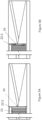
- Figures 4 , 5A and 5B illustrate an open view of another embodiment of the thruster 2.
- the principle of contacting and releasing the sealing surface 24 is similar compared to the one described in relation to Figure 2 .
- the whole thruster 2 may be made as a laminar part with laminated ceramics or as a part of micro-electromechanical systems (MEMS).
- MEMS micro-electromechanical systems
- Laminar and MEMS lithography technologies allow construction from single block of raw material which reduces assembly and seams in the final product. Using this technology allows the thruster to be further miniaturized into a nanotechnological structure. This can allow a triple integration, where the nozzle 25, the valve component 22 and the heating element 23 are integrated in the same system.
- the valve component 22 in this embodiment is arranged as a valve strip 22-2 with higher thermal expansion coefficient than the thruster body 21.
- the laminar structure may allow the propellant channel 5 and the nozzle 25 to be manufactured directly to the same part with the thruster body 21. The ability to manufacture the propellant channel 5 to the same part with the thruster body improves the manufacturability of the entire thruster 2.
- the valve strip 22-2 can be made of one or more materials, such as titanium or copper-titanium bimetal.
- the valve strip 22-2 can be manufactured out of a single functional material design. It comprises at least one aperture 27 or other feature for allowing flow, and a surface which contacts an entrance of the nozzle 25 and the thruster body 21, forming the sealing surface 24, when the thruster 2 is in the first temperature, as shown in Figure 5A , and opens the nozzle 25 when the thruster 2 is heated to the second temperature, as shown in Figure 5B .
- Both ends of the valve strip 22-2 are constrained by the thruster body 21 in such a way to prevent the valve strip 22-2 from shifting inside the thruster body 21. This can be achieved for instance by features such as notches in the thruster body 21 or a solid connection between the two, such as a weld.
- valve strip 22-2 When in the first temperature, the valve strip 22-2 is straight and having a same width as the space 20 closest to the nozzle 25 and the side towards the nozzle 25 is in contact with the thruster body wall such way that the sealing surface 24 is contacted because the apertures 27, the sealing surface 24 or both are blocked by said wall. Because the thermal expansion of the valve strip 22-2 is higher than the thruster body 21, or in the case of a bimetal strip, the thermal expansion of the side towards the nozzle 25 is lower, it allows the valve strip 22-2 to bend inwards towards the space 20. The bending releases the sealing surface 24 and opens the nozzle 25 and allowing the propellant to flow through the apertures 27 which are no longer blocked by said wall.
- the electrically controlled heating element 23 can comprise a resistive element situated inside the thruster body 21 that can be for instance selectively plated on the thruster body 21.
- the electrically controlled heating element 23 can alternatively be situated outside the thruster body 21.
- the thruster 2 can be less than 5 mm long. In some embodiments, only 2 parts are needed to assemble the whole thruster 2. Decreasing the number of the components also decreases the number of possible causes of failure which results in higher product reliability and decreasing system assembly time and weight.
- the design allows manufacturability in series production while increasing the component quality and repeatability in production. It also allows the scalability of the maximum thrust and impulse allowing the same basic design for a large range of thrust levels.
Landscapes
- Engineering & Computer Science (AREA)
- Combustion & Propulsion (AREA)
- Chemical & Material Sciences (AREA)
- General Engineering & Computer Science (AREA)
- Physics & Mathematics (AREA)
- Mechanical Engineering (AREA)
- Remote Sensing (AREA)
- Aviation & Aerospace Engineering (AREA)
- Plasma & Fusion (AREA)
- General Physics & Mathematics (AREA)
- Automation & Control Theory (AREA)
- Details Of Valves (AREA)
- Lift Valve (AREA)
- Temperature-Responsive Valves (AREA)
- Radar, Positioning & Navigation (AREA)
- Astronomy & Astrophysics (AREA)
Description
- The present invention relates to a propulsion engine, and more particularly to an electrothermal thruster assembly.
- Recent trend in satellite size have been towards highly miniaturized propulsion systems. A CubeSat is a type of miniaturized satellite for space research that is made up of multiples of 10 cm × 10 cm × 10 cm cubic units. CubeSats and similar smaller satellites have raised a demand for miniature propulsion systems, and a great majority of recent and upcoming launches are in the CubeSat size range. Mission goals range from simple technological experimentations aiming to increase the educational know-how about space technology to highly specialized scientific mission tailored for diverse research programs. For instance,
DE2054062A1 andUS2013167377A1 disclose a thruster assembly for a propulsion system. - Some of the problems associated with miniaturing a propulsion system is how to accurately control the satellite attitude. For instance, the research missions typically require exact aiming of their instruments at the Earth, the Sun, or at some fixed points in the celestial sphere. In many cases, the scientific value of the mission may even be critically dependable on the precise controllability of the satellite and the real-time information about the satellite attitude.
- Besides the obvious needs in instrument aiming, attitude control can be used as a tool to prolong satellite operational lifetime as it enables e.g. optimal aiming of solar panels for the generation of electrical energy, and satellite attitude adjustments to minimize air drag on Low Earth Orbits (LEO) that would otherwise lead to premature deorbiting. Other use includes collision avoidance that can be efficiently achieved even with one thruster system.
- Designing and mass-manufacturing a reliable and cost-effective solution on the growing demand of thruster systems that would equip small satellites with the attitude control and small orbit change capabilities require high competence in micromechanics and microelectronics.
- An object of the present invention is to provide an assembly to solve the above problems. The objects of the invention are achieved by an arrangement which are characterized by what is stated in the independent claim. The preferred embodiments of the invention are disclosed in the dependent claims.
- The invention is based on the idea of a thruster which comprises a thruster body and a valve component having different thermal expansion coefficients.
- Advantages of the arrangement is to provide a well-suited thruster system for series production that is reliable in miniaturisation and controllability.
- In the following the invention will be described in greater detail by means of preferred embodiments with reference to the accompanying drawings, in which
-
Figure 1 illustrates an embodiment of a thruster assembly; -
Figure 2 illustrates a cross-sectional view of a first embodiment of a thruster; -
Figures 3A-3D illustrates additional examples of the first embodiment of the thruster; -
Figure 4 illustrates an open view of a second embodiment of a thruster; -
Figure 5A illustrates the embodiment ofFigure 4 in a first temperature andFigure 5B in a second temperature. -
Figure 1 illustrates an embodiment of a thruster assembly, which comprises aswitch 1, athruster 2, a propellant tank 3, a main valve 4 and apropellant channel 5. Theswitch 1 can be part of the electrical control system, which is connected to a power source, for instance photovoltaic cells. The propellant tank 3 is for storing and pressurising a propellant. A suitable propellant can be for instance water or other gasifiable or gaseous substance or mixture such as xenon. The main valve 4 is configured to control the propellant flow through thepropellant channel 5 which guides the propellant to thethruster 2, where it is heated and expelled which generates propulsion to move the thruster assembly and consequently the satellite or spacecraft attached to it. The main valve 4 adds additional security against leaks when operating in vacuum. A small impulse bit from themain valve 2 enables accurate positioning and dynamic control when moving a spacecraft. - The propellant tank 3 may be connected to more than one main valve 4 and the main valve 4 may control the propellant flow to more than one
thruster 2. In some embodiments of a thruster assembly, thepropellant channel 5 may be directly connected to the tank 3 without a main valve 4. The propellant is fed to thethruster 2 by pressurizing the propellant in the tank 3 with a diaphragm or bladder structure using a pressurizing agent or a mechanical spring, or by other means such as mechanical pumping or using the propellant itself as a pressurizing agent. In some embodiments one end of thepropellant channel 5 can be joined to thethruster 2 in a fixed connection, and in some embodiments thepropellant channel 5 can be manufactured as part of thethruster 2. In some embodiments thepropellant channel 5 can be a capillary pipe. By using the capillary pipe, the pressure in the propellant tank 3 can be kept lower compared to other types of channels. -
Figure 2 illustrates a cross-sectional view of an embodiment of the thruster. Thethruster 2 comprises athruster body 21, avalve component 22, aspace 20 between thethruster body 21 and thevalve component 22, an electrically controlledheating element 23 and anozzle 25. Thespace 20 is for receiving the propellant from thepropellant channel 5 and heating the propellant before it is released to thenozzle 25. - The
thruster body 21 can be a hollow housing made of a material with a first thermal expansion coefficient, and it can be for instance titanium with the linear thermal expansion coefficient of 9 10-6 K-1. Thevalve component 22 is arranged inside thethruster body 21 and it can be a capsule 22-1 comprising a cylindrical section with hemispherical ends. This kind of shape is simple to manufacture in micro scale, when designing miniaturized satellites. In some embodiments, other shapes can also be implemented, such as a ball or a needle with varying diameters. Thevalve component 22 is made of a material with a second thermal expansion coefficient, which is different than said first thermal expansion coefficient, and it can be for instance silicon with the linear thermal expansion coefficient of 3 10-6 K-1. - In this embodiment, the first thermal expansion coefficient is bigger than the second thermal expansion coefficient. In another embodiment, the first thermal expansion coefficient can be smaller than the second thermal expansion coefficient. Different materials have different thermal expansion coefficients and the most preferable material duos are metallic and ceramic, such as stainless steel and silicon carbide, or metals with large difference in thermal expansion coefficients, such as copper or aluminium, or other materials with sufficient operating temperature and thermal expansion coefficient difference. The linear thermal expansion coefficient difference is selected in accordance with the desired temperature difference between nominal and working temperature and other parameters such as the thruster size and static installation stress. A lower thermal expansion coefficient difference requires a larger difference in temperature.
- The electrically controlled
heating element 23 is configured to heat thethruster 2 in response to actuation of theswitch 1 from a first temperature to a second temperature. For instance, the first temperature may be the spacecraft's regulated body temperature, which is typically -5... 20 °C, and the second temperature may be 600... 1000 °C where the thermal expansion caused by thethruster body 21 and thevalve component 22 comprising asealing surface 24 closes thenozzle 25. The electrically controlledheating element 23 can comprise for instance a resistive wire coiled around thethruster body 21 or any other heating element to heat thethruster 2 to the second temperature such as an induction heater or a selectively plated resistive layer on nonconductive material. For example, a difference in thermal expansion coefficients of 5 10-6 K-1 with a 10 mm long valve component and 800 °C temperature difference from the first temperature to the second temperature produces a gap of 0.04 mm at thesealing surface 24, which is suitable for allowing the propellant flow in thethruster 2. When the propellant is heated to the second temperature, the pressure increases because of kinetic energy and causes the thruster assembly to move in space when the heated gas is expelled from thenozzle 25. When the electrically controlledheating element 23 cools down, the temperature of thethruster 2 decreases back to the first temperature and thesealing surface 24 closes thenozzle 25 again. The electrically controlledheating element 23 enables fast electric control of the thrust by controlling both thevalve component 22 and heating the propellant. It is a simple and efficient solution to drive thethruster 2 on and off. - As shown in
Figure 2 , at the first temperature, thevalve component 22 is compressed between thethruster body 21 and thepropellant channel 5, and thevalve component 22 having thesealing surface 24 where thepropellant channel 5 contacts saidvalve component 22. Thethruster body 21 and thepropellant channel 5 are in the fixed connection by laser welding, for instance. The sealing surface inFigure 2 refers to the surface of thevalve component 22 contacting thepropellant channel 5. However, in another embodiment (for instanceFigures 3A-3D ), it may refer to the surface of thevalve component 22 contacting thethruster body 21. When contacting, thenozzle 25 is closed and prevents the propellant to be expelled. This structure allows simultaneously propellant heating and valve operations. Thevalve component 22 will cool down faster after heating power is turned off and increases reaction speed of thethruster 2. - When heated to the second temperature, the
thruster body 21 is expanding more than the valve component and thus, releasing the sealingsurface 24 from thepropellant channel 5. Releasing in this context refers to separating thevalve component 22 and thepropellant channel 5 or thethruster body 21, and forming the gap at the sealingsurface 24 and thus, opening thenozzle 25. When the sealingsurface 24 is released, thevalve component 22 may move inside thespace 20 and is pushed towards thenozzle 25 by the pressure of the propellant. In some embodiments, the front end of thevalve component 22 further compriseschannels 28 so the propellant flow is not restricted when thevalve component 22 is pressed towards thenozzle 25. In this context, the front end refers to the end closest to thenozzle 25. - The sealing
surface 24 is configured to be contacted when thethruster body 21 and thevalve component 22 are in the first temperature which prevents the propellant leaking towards thenozzle 25. The sealingsurface 24 is configured to be released when thethruster body 21 and thevalve component 22 are in the second temperature which allows the propellant to pass towards thenozzle 25. In some embodiments, one end of thevalve component 22 is in fixed connection with thethruster body 21, which can be achieved with laser welding or thevalve component 22 and thethruster body 21 threaded together, for instance. Fixing thevalve component 22 with thethruster body 21 enables the temperature difference required for releasing the sealingsurface 24 to be adjusted by changing temperature and force with which thevalve component 22 is inserted to thethruster body 21 during assembly to induce a stress in the materials. Thevalve component 22 or thethruster body 21 may comprise flow channels similar to thechannels 28 mentioned above for passing the propellant towards thenozzle 25 when thevalve component 22 is in fixed connection with thethruster body 21. Said flow channels can be at a location of the fixed connection or next to it. Thevalve component 22 may be freely floating between constricting elements allowing more extreme differential thermal expansion. - The
nozzle 25 is manufactured as part of thethruster body 21 and comprise a propelling nozzle bore such as a converging-diverging nozzle. The converging-diverging nozzle is shaped like a tube that is narrowed or pinched in the middle and arranged as asymmetric hourglass shape. It is used to accelerate a hot, pressurized propellant passing through it to a higher supersonic speed in the thrust direction, by converting the heat energy of the flow into kinetic energy resulting in an additional turbo boost. At the propelling nozzle bore, where the cross-sectional area is at its minimum, the propellant velocity locally becomes sonic. As the converging-diverging nozzle cross-sectional area increases, the propellant begins to expand, and the propellant flow increases to supersonic velocities. As the propellant exits the propelling nozzle bore, the increase in area allows for it to undergo a Joule-Thompson expansion wherein the propellant expands at supersonic speeds from high to low pressure pushing the velocity of the mass flow beyond sonic speed. This reduces power consumption and increases the thrust, as well as enables the integration of the system into multiple propellant systems and the utilization of different propellants. - Manufacturing the
nozzle 25 as part of thethruster body 21 refers to one solid piece where thenozzle 25 is integrated with thethruster body 21. The integrated structure can make a cold gas system with a simple change of the thruster tip. This increases usable applications of thethruster 2 when the cold gas system can convert to a hot gas system with the turbo boost by heating notonly valve component 22 but as well as the propellant. - The electrically controlled
heating element 23 can be insulated with theinsulator 26 such as glass fibre or other nonconductive material around theheating element 23 to electrically insulate it from itself and thethruster body 21. Thethruster body 21 and the insulated electrically controlledheating element 23 can be further surrounded by asleeve 29 to keep the electrically controlledheating element 23 in place and reflect some of the heat radiated but thethruster body 21 and theheating element 23 back towards thethruster body 21. Thesleeve 29 in this context refers to an outer layer of thethruster 2 and it can be made of same or a different material as thethruster body 21. Theheating element 23 may affect specially the nozzle section, with its specific temperature as well as the thermal expansion coefficient, which is different from the one in the earlier section of thethruster 2. -
Figures 3A-3D illustrates additional examples how thethruster body 21, thevalve component 22, thespace 20, the sealingsurface 24 and thenozzle 25 can be designed. The sealingsurface 24 of thevalve component 22 inFigures 3A-3D is the surface contacting thethruster body 21. All of them follow the same principle where thethruster body 21 has a different thermal expansion coefficient compared to the thermal expansion coefficient of thevalve component 22. For instance, inFigures 3A and 3B , thevalve component 22 has lower thermal expansion coefficient compared to the thermal expansion coefficient of thethruster body 21, and inFigures 3C and 3D , thevalve component 22 has higher thermal expansion coefficient compared to the thermal expansion coefficient of thethruster body 21. In cases of 3C and 3D, the thermal expansion allows thevalve component 22 to elongate more than thethruster body 21 and thus releasing the sealingsurface 24. The sealingsurface 24 can situate closer to thenozzle 25 as shown inFigures 3A and 3C , or it can situate closer to thepropellant channel 5 as shown inFigures 3B and 3D . -
Figures 4 ,5A and 5B illustrate an open view of another embodiment of thethruster 2. The principle of contacting and releasing the sealingsurface 24 is similar compared to the one described in relation toFigure 2 . However, in this implementation, thewhole thruster 2 may be made as a laminar part with laminated ceramics or as a part of micro-electromechanical systems (MEMS). Laminar and MEMS lithography technologies allow construction from single block of raw material which reduces assembly and seams in the final product. Using this technology allows the thruster to be further miniaturized into a nanotechnological structure. This can allow a triple integration, where thenozzle 25, thevalve component 22 and theheating element 23 are integrated in the same system. Thevalve component 22 in this embodiment is arranged as a valve strip 22-2 with higher thermal expansion coefficient than thethruster body 21. In some embodiments, the laminar structure may allow thepropellant channel 5 and thenozzle 25 to be manufactured directly to the same part with thethruster body 21. The ability to manufacture thepropellant channel 5 to the same part with the thruster body improves the manufacturability of theentire thruster 2. - The valve strip 22-2 can be made of one or more materials, such as titanium or copper-titanium bimetal. The valve strip 22-2 can be manufactured out of a single functional material design. It comprises at least one
aperture 27 or other feature for allowing flow, and a surface which contacts an entrance of thenozzle 25 and thethruster body 21, forming the sealingsurface 24, when thethruster 2 is in the first temperature, as shown inFigure 5A , and opens thenozzle 25 when thethruster 2 is heated to the second temperature, as shown inFigure 5B . Both ends of the valve strip 22-2 are constrained by thethruster body 21 in such a way to prevent the valve strip 22-2 from shifting inside thethruster body 21. This can be achieved for instance by features such as notches in thethruster body 21 or a solid connection between the two, such as a weld. - When in the first temperature, the valve strip 22-2 is straight and having a same width as the
space 20 closest to thenozzle 25 and the side towards thenozzle 25 is in contact with the thruster body wall such way that the sealingsurface 24 is contacted because theapertures 27, the sealingsurface 24 or both are blocked by said wall. Because the thermal expansion of the valve strip 22-2 is higher than thethruster body 21, or in the case of a bimetal strip, the thermal expansion of the side towards thenozzle 25 is lower, it allows the valve strip 22-2 to bend inwards towards thespace 20. The bending releases the sealingsurface 24 and opens thenozzle 25 and allowing the propellant to flow through theapertures 27 which are no longer blocked by said wall. - The electrically controlled
heating element 23 can comprise a resistive element situated inside thethruster body 21 that can be for instance selectively plated on thethruster body 21. The electrically controlledheating element 23 can alternatively be situated outside thethruster body 21. - With above-mentioned thruster designs, a limited number of components and miniaturisation can be realized. The
thruster 2 can be less than 5 mm long. In some embodiments, only 2 parts are needed to assemble thewhole thruster 2. Decreasing the number of the components also decreases the number of possible causes of failure which results in higher product reliability and decreasing system assembly time and weight. The design allows manufacturability in series production while increasing the component quality and repeatability in production. It also allows the scalability of the maximum thrust and impulse allowing the same basic design for a large range of thrust levels.
Claims (13)
- A thruster assembly, comprisinga switch (1) connected to a power source,a thruster (2),a propellant tank (3) for storing and pressurising a propellant, anda propellant channel (5) for guiding the propellant to the thruster (2), wherein the thruster (2) comprises:a space (20) for receiving the propellant from the propellant channel (5),an electrically controlled heating element (23),a thruster body (21) having a first thermal expansion coefficient,a valve component (22) having a second thermal expansion coefficient, which is different than the first thermal expansion coefficient, inside the thruster body (21),a converging-diverging nozzle (25) comprising a propelling nozzle bore,wherein the valve component (22) comprises a sealing surface (24) closing the converging-diverging nozzle (25) in a first temperature, andthe electrically controlled heating element (23) in response to actuation of the switch (1) heats said thruster (2) to a second temperature where the thermal expansion of the thruster (2) opens the converging-diverging nozzle (25), characterized in that the converging-diverging nozzle (25) is manufactured to a same part with the thruster body (21).
- A thruster assembly according to claim 1, wherein one end of the valve component (22) is in fixed connection with the thruster body (21).
- A thruster assembly according to claim 1, wherein the valve component (22) is a capsule (22-1) comprising a cylindrical section.
- A thruster assembly according to any of claims 1-3, wherein the thruster body (21) has a higher thermal expansion coefficient than the valve component (22).
- A thruster assembly according to claim 1, wherein the thruster body (21) comprises of a laminar structure with laminated ceramics or MEMS.
- A thruster assembly according to claim 5, wherein the valve component (22) is a valve strip (22-2) comprising at least one aperture (27).
- A thruster assembly according to claim 6, wherein the valve strip (22-2) has a higher thermal expansion coefficient than the thruster body (21), and both ends of the valve strip (22-2) are in fixed connection with the thruster body (21) such that when heated to the second temperature, the valve strip (22-2) is configured to bend inward because of the thermal expansion.
- A thruster assembly according to any of claims 5-7, wherein the laminar structure allows the propellant channel (5) to be manufactured to the same part with the thruster body (21).
- A thruster assembly according to any of claims 1-8, wherein the sealing surface (24) is a surface of the valve component (22) contacting the thruster body (21), or a surface of the valve component (22) contacting the propellant channel (5).
- A thruster assembly according to any of claims 1-9, wherein the thruster body (21) is surrounded by a sleeve (29).
- A thruster assembly according to any of claims 1-10, wherein the assembly further comprises a main valve (4) for controlling propellant flow to the thruster (2).
- A thruster assembly according to any claims 1-11, wherein the electrically controlled heating element (23) comprises a resistive wire coiled around the thruster body (21) or situated inside the thruster body (21).
- A thruster assembly according to any of claims 1-12, wherein the thruster (2) is less than 5 mm long.
Applications Claiming Priority (2)
| Application Number | Priority Date | Filing Date | Title |
|---|---|---|---|
| FI20205344A FI129831B (en) | 2020-04-02 | 2020-04-02 | SHOOTING UNIT |
| PCT/FI2021/050247 WO2021198570A1 (en) | 2020-04-02 | 2021-04-01 | Thruster assembly |
Publications (3)
| Publication Number | Publication Date |
|---|---|
| EP4127443A1 EP4127443A1 (en) | 2023-02-08 |
| EP4127443B1 true EP4127443B1 (en) | 2023-11-15 |
| EP4127443C0 EP4127443C0 (en) | 2023-11-15 |
Family
ID=75787124
Family Applications (1)
| Application Number | Title | Priority Date | Filing Date |
|---|---|---|---|
| EP21723310.5A Active EP4127443B1 (en) | 2020-04-02 | 2021-04-01 | Thruster assembly |
Country Status (6)
| Country | Link |
|---|---|
| US (1) | US12345245B2 (en) |
| EP (1) | EP4127443B1 (en) |
| JP (1) | JP7425895B2 (en) |
| ES (1) | ES2973264T3 (en) |
| FI (1) | FI129831B (en) |
| WO (1) | WO2021198570A1 (en) |
Families Citing this family (2)
| Publication number | Priority date | Publication date | Assignee | Title |
|---|---|---|---|---|
| KR102671438B1 (en) * | 2022-03-31 | 2024-05-30 | 세종대학교산학협력단 | Field emission electric propulsion system for satellites using liquid metal gallium as propellant |
| US12601312B2 (en) * | 2024-01-24 | 2026-04-14 | Aerojet Rocketdyne, Inc. | Warm gas thruster system with control valve that has a soft seal |
Family Cites Families (13)
| Publication number | Priority date | Publication date | Assignee | Title |
|---|---|---|---|---|
| US2960303A (en) * | 1955-04-22 | 1960-11-15 | Cosby D P Smallpeice | Fluid control valve |
| FR2678751A1 (en) | 1991-07-03 | 1993-01-08 | Europ Agence Spatiale | ELECTRONICALLY CONTROLLED FLUID PRESSURE REGULATOR AND THERMALLY CONTROLLED VALVE, PARTICULARLY FOR FLUIDS FOR SUPPLYING SPACE ENGINES. |
| GB9127433D0 (en) * | 1991-12-27 | 1992-02-19 | Matra Marconi Space Uk | Propulsion system for spacecraft |
| FR2734025B1 (en) * | 1995-05-11 | 1997-08-01 | Europ Propulsion | PULSED LIQUID PROPERTY PULSE MOTOR |
| CA2257341A1 (en) | 1996-06-07 | 1997-12-11 | Robert H. Reinicke | Micro gas rheostat |
| DE19937603C2 (en) * | 1999-08-09 | 2002-08-01 | Max Planck Gesellschaft | Device and method for gas metering |
| US8499779B2 (en) * | 2008-01-16 | 2013-08-06 | The United States Of America As Represented By The Administrator Of The National Aeronautics Space Administration | Systems, methods and apparatus of a nitinol valve |
| GB2464954B (en) | 2008-10-30 | 2012-06-20 | Univ Open | Valve |
| US8707675B2 (en) * | 2011-01-20 | 2014-04-29 | Honeywell International Inc. | Pressure assisted direct drive proportional hot-gas thruster |
| US9777674B2 (en) * | 2014-02-26 | 2017-10-03 | Deepak Atyam | Injector plate for a rocket engine |
| DE102016212581B4 (en) | 2016-07-11 | 2019-07-04 | Arianegroup Gmbh | Valve for selectively opening a fluid line in a satellite propulsion system and satellite propulsion system |
| DE102017212927B4 (en) | 2017-07-27 | 2019-05-02 | Airbus Defence and Space GmbH | Electric engine and method of operating an electric engine |
| FR3069899B1 (en) | 2017-08-04 | 2020-05-08 | L'air Liquide, Societe Anonyme Pour L'etude Et L'exploitation Des Procedes Georges Claude | REGULATING VALVE AND PROPELLING DEVICE |
-
2020
- 2020-04-02 FI FI20205344A patent/FI129831B/en active IP Right Grant
-
2021
- 2021-04-01 JP JP2022560287A patent/JP7425895B2/en active Active
- 2021-04-01 ES ES21723310T patent/ES2973264T3/en active Active
- 2021-04-01 EP EP21723310.5A patent/EP4127443B1/en active Active
- 2021-04-01 WO PCT/FI2021/050247 patent/WO2021198570A1/en not_active Ceased
- 2021-04-01 US US17/916,456 patent/US12345245B2/en active Active
Also Published As
| Publication number | Publication date |
|---|---|
| ES2973264T3 (en) | 2024-06-19 |
| JP7425895B2 (en) | 2024-01-31 |
| FI129831B (en) | 2022-09-15 |
| US12345245B2 (en) | 2025-07-01 |
| EP4127443C0 (en) | 2023-11-15 |
| EP4127443A1 (en) | 2023-02-08 |
| FI20205344A1 (en) | 2021-10-03 |
| WO2021198570A1 (en) | 2021-10-07 |
| US20230037400A1 (en) | 2023-02-09 |
| JP2023520894A (en) | 2023-05-22 |
Similar Documents
| Publication | Publication Date | Title |
|---|---|---|
| EP4127443B1 (en) | Thruster assembly | |
| Rossi et al. | Micropyrotechnics, a new technology for making energetic microsystems: review and prospective | |
| US6131385A (en) | Integrated pulsed propulsion system for microsatellite | |
| Ye et al. | Study of a vaporizing water micro-thruster | |
| US20110240801A1 (en) | microsatellite comprising a propulsion module and an imaging device | |
| US11867319B2 (en) | Microelectronic thermal valve | |
| Ketsdever et al. | Performance testing of a microfabricated propulsion system for nanosatellite applications | |
| Larangot et al. | Solid propellant microthruster: an alternative propulsion device for nanosatellite | |
| Mueller | A review and applicability assessment of MEMS-based microvalve technologies for microspacecraft propulsion | |
| Huh et al. | Microcooling channel effect on a monopropellant microelectromechanical system thruster performance | |
| FI13235Y1 (en) | Thruster assembly | |
| US6539703B1 (en) | Spacecraft component with microthruster actuation and operation thereof | |
| Colón et al. | Spectre: Design of a Dual-Mode Green Monopropellant Propulsion System | |
| Mueller et al. | Towards micropropulsion systems on-a-chip: initial results of component feasibility studies | |
| Rhee et al. | Highlights of nanosatellite propulsion development program at NASA-Goddard space flight center | |
| Kural et al. | Design of an ion thruster movable grid thrust vectoring system | |
| US8405012B1 (en) | Out-of-plane deflection MEMS actuator for projectile control surfaces | |
| Bzibziak | Update of cold gas propulsion at Moog | |
| US12320340B1 (en) | Electrothermal subassembly of steam thruster for nanosatellites | |
| RU2834321C1 (en) | Electrothermal unit of steam engine for nanosatellites | |
| EP1941197A1 (en) | A high pressure isolation valve system | |
| Gauer et al. | PRECISE-preliminary results of the MEMS-based µCPS | |
| Wu | Development and experimental analyses of meso and micro scale combustion systems | |
| KATKURI et al. | Micro-propulsion for space applications: a review of traditional and innovative systems | |
| Larsen et al. | FABRICATION OF LTCC BASED MICRO THRUSTER FOR PRECISION CONTROLLED SPACE FLIGHT POWERMEMS 2011 |
Legal Events
| Date | Code | Title | Description |
|---|---|---|---|
| STAA | Information on the status of an ep patent application or granted ep patent |
Free format text: STATUS: UNKNOWN |
|
| STAA | Information on the status of an ep patent application or granted ep patent |
Free format text: STATUS: THE INTERNATIONAL PUBLICATION HAS BEEN MADE |
|
| PUAI | Public reference made under article 153(3) epc to a published international application that has entered the european phase |
Free format text: ORIGINAL CODE: 0009012 |
|
| STAA | Information on the status of an ep patent application or granted ep patent |
Free format text: STATUS: REQUEST FOR EXAMINATION WAS MADE |
|
| 17P | Request for examination filed |
Effective date: 20221020 |
|
| AK | Designated contracting states |
Kind code of ref document: A1 Designated state(s): AL AT BE BG CH CY CZ DE DK EE ES FI FR GB GR HR HU IE IS IT LI LT LU LV MC MK MT NL NO PL PT RO RS SE SI SK SM TR |
|
| GRAP | Despatch of communication of intention to grant a patent |
Free format text: ORIGINAL CODE: EPIDOSNIGR1 |
|
| STAA | Information on the status of an ep patent application or granted ep patent |
Free format text: STATUS: GRANT OF PATENT IS INTENDED |
|
| DAV | Request for validation of the european patent (deleted) | ||
| DAX | Request for extension of the european patent (deleted) | ||
| INTG | Intention to grant announced |
Effective date: 20230614 |
|
| GRAS | Grant fee paid |
Free format text: ORIGINAL CODE: EPIDOSNIGR3 |
|
| GRAA | (expected) grant |
Free format text: ORIGINAL CODE: 0009210 |
|
| STAA | Information on the status of an ep patent application or granted ep patent |
Free format text: STATUS: THE PATENT HAS BEEN GRANTED |
|
| AK | Designated contracting states |
Kind code of ref document: B1 Designated state(s): AL AT BE BG CH CY CZ DE DK EE ES FI FR GB GR HR HU IE IS IT LI LT LU LV MC MK MT NL NO PL PT RO RS SE SI SK SM TR |
|
| REG | Reference to a national code |
Ref country code: CH Ref legal event code: EP Ref country code: GB Ref legal event code: FG4D |
|
| REG | Reference to a national code |
Ref country code: DE Ref legal event code: R096 Ref document number: 602021006881 Country of ref document: DE |
|
| REG | Reference to a national code |
Ref country code: IE Ref legal event code: FG4D |
|
| U01 | Request for unitary effect filed |
Effective date: 20231212 |
|
| U07 | Unitary effect registered |
Designated state(s): AT BE BG DE DK EE FI FR IT LT LU LV MT NL PT SE SI Effective date: 20231218 |
|
| REG | Reference to a national code |
Ref country code: NO Ref legal event code: T2 Effective date: 20231115 |
|
| PG25 | Lapsed in a contracting state [announced via postgrant information from national office to epo] |
Ref country code: GR Free format text: LAPSE BECAUSE OF FAILURE TO SUBMIT A TRANSLATION OF THE DESCRIPTION OR TO PAY THE FEE WITHIN THE PRESCRIBED TIME-LIMIT Effective date: 20240216 |
|
| PG25 | Lapsed in a contracting state [announced via postgrant information from national office to epo] |
Ref country code: IS Free format text: LAPSE BECAUSE OF FAILURE TO SUBMIT A TRANSLATION OF THE DESCRIPTION OR TO PAY THE FEE WITHIN THE PRESCRIBED TIME-LIMIT Effective date: 20240315 |
|
| PG25 | Lapsed in a contracting state [announced via postgrant information from national office to epo] |
Ref country code: IS Free format text: LAPSE BECAUSE OF FAILURE TO SUBMIT A TRANSLATION OF THE DESCRIPTION OR TO PAY THE FEE WITHIN THE PRESCRIBED TIME-LIMIT Effective date: 20240315 Ref country code: GR Free format text: LAPSE BECAUSE OF FAILURE TO SUBMIT A TRANSLATION OF THE DESCRIPTION OR TO PAY THE FEE WITHIN THE PRESCRIBED TIME-LIMIT Effective date: 20240216 |
|
| U20 | Renewal fee for the european patent with unitary effect paid |
Year of fee payment: 4 Effective date: 20240416 |
|
| PG25 | Lapsed in a contracting state [announced via postgrant information from national office to epo] |
Ref country code: RS Free format text: LAPSE BECAUSE OF FAILURE TO SUBMIT A TRANSLATION OF THE DESCRIPTION OR TO PAY THE FEE WITHIN THE PRESCRIBED TIME-LIMIT Effective date: 20231115 Ref country code: PL Free format text: LAPSE BECAUSE OF FAILURE TO SUBMIT A TRANSLATION OF THE DESCRIPTION OR TO PAY THE FEE WITHIN THE PRESCRIBED TIME-LIMIT Effective date: 20231115 Ref country code: HR Free format text: LAPSE BECAUSE OF FAILURE TO SUBMIT A TRANSLATION OF THE DESCRIPTION OR TO PAY THE FEE WITHIN THE PRESCRIBED TIME-LIMIT Effective date: 20231115 |
|
| REG | Reference to a national code |
Ref country code: ES Ref legal event code: FG2A Ref document number: 2973264 Country of ref document: ES Kind code of ref document: T3 Effective date: 20240619 |
|
| PG25 | Lapsed in a contracting state [announced via postgrant information from national office to epo] |
Ref country code: CZ Free format text: LAPSE BECAUSE OF FAILURE TO SUBMIT A TRANSLATION OF THE DESCRIPTION OR TO PAY THE FEE WITHIN THE PRESCRIBED TIME-LIMIT Effective date: 20231115 |
|
| PG25 | Lapsed in a contracting state [announced via postgrant information from national office to epo] |
Ref country code: SK Free format text: LAPSE BECAUSE OF FAILURE TO SUBMIT A TRANSLATION OF THE DESCRIPTION OR TO PAY THE FEE WITHIN THE PRESCRIBED TIME-LIMIT Effective date: 20231115 |
|
| PG25 | Lapsed in a contracting state [announced via postgrant information from national office to epo] |
Ref country code: SM Free format text: LAPSE BECAUSE OF FAILURE TO SUBMIT A TRANSLATION OF THE DESCRIPTION OR TO PAY THE FEE WITHIN THE PRESCRIBED TIME-LIMIT Effective date: 20231115 Ref country code: SK Free format text: LAPSE BECAUSE OF FAILURE TO SUBMIT A TRANSLATION OF THE DESCRIPTION OR TO PAY THE FEE WITHIN THE PRESCRIBED TIME-LIMIT Effective date: 20231115 Ref country code: RO Free format text: LAPSE BECAUSE OF FAILURE TO SUBMIT A TRANSLATION OF THE DESCRIPTION OR TO PAY THE FEE WITHIN THE PRESCRIBED TIME-LIMIT Effective date: 20231115 Ref country code: CZ Free format text: LAPSE BECAUSE OF FAILURE TO SUBMIT A TRANSLATION OF THE DESCRIPTION OR TO PAY THE FEE WITHIN THE PRESCRIBED TIME-LIMIT Effective date: 20231115 |
|
| REG | Reference to a national code |
Ref country code: DE Ref legal event code: R097 Ref document number: 602021006881 Country of ref document: DE |
|
| PLBE | No opposition filed within time limit |
Free format text: ORIGINAL CODE: 0009261 |
|
| STAA | Information on the status of an ep patent application or granted ep patent |
Free format text: STATUS: NO OPPOSITION FILED WITHIN TIME LIMIT |
|
| 26N | No opposition filed |
Effective date: 20240819 |
|
| PG25 | Lapsed in a contracting state [announced via postgrant information from national office to epo] |
Ref country code: MC Free format text: LAPSE BECAUSE OF FAILURE TO SUBMIT A TRANSLATION OF THE DESCRIPTION OR TO PAY THE FEE WITHIN THE PRESCRIBED TIME-LIMIT Effective date: 20231115 |
|
| PG25 | Lapsed in a contracting state [announced via postgrant information from national office to epo] |
Ref country code: MC Free format text: LAPSE BECAUSE OF FAILURE TO SUBMIT A TRANSLATION OF THE DESCRIPTION OR TO PAY THE FEE WITHIN THE PRESCRIBED TIME-LIMIT Effective date: 20231115 |
|
| REG | Reference to a national code |
Ref country code: CH Ref legal event code: PL |
|
| PG25 | Lapsed in a contracting state [announced via postgrant information from national office to epo] |
Ref country code: CH Free format text: LAPSE BECAUSE OF NON-PAYMENT OF DUE FEES Effective date: 20240430 |
|
| PG25 | Lapsed in a contracting state [announced via postgrant information from national office to epo] |
Ref country code: IE Free format text: LAPSE BECAUSE OF NON-PAYMENT OF DUE FEES Effective date: 20240401 |
|
| U20 | Renewal fee for the european patent with unitary effect paid |
Year of fee payment: 5 Effective date: 20250416 |
|
| PGFP | Annual fee paid to national office [announced via postgrant information from national office to epo] |
Ref country code: NO Payment date: 20250404 Year of fee payment: 5 |
|
| PG25 | Lapsed in a contracting state [announced via postgrant information from national office to epo] |
Ref country code: CY Free format text: LAPSE BECAUSE OF FAILURE TO SUBMIT A TRANSLATION OF THE DESCRIPTION OR TO PAY THE FEE WITHIN THE PRESCRIBED TIME-LIMIT; INVALID AB INITIO Effective date: 20210401 |
|
| PG25 | Lapsed in a contracting state [announced via postgrant information from national office to epo] |
Ref country code: HU Free format text: LAPSE BECAUSE OF FAILURE TO SUBMIT A TRANSLATION OF THE DESCRIPTION OR TO PAY THE FEE WITHIN THE PRESCRIBED TIME-LIMIT; INVALID AB INITIO Effective date: 20210401 |
|
| PGFP | Annual fee paid to national office [announced via postgrant information from national office to epo] |
Ref country code: ES Payment date: 20250714 Year of fee payment: 5 |
|
| PG25 | Lapsed in a contracting state [announced via postgrant information from national office to epo] |
Ref country code: TR Free format text: LAPSE BECAUSE OF FAILURE TO SUBMIT A TRANSLATION OF THE DESCRIPTION OR TO PAY THE FEE WITHIN THE PRESCRIBED TIME-LIMIT Effective date: 20231115 |
|
| PGFP | Annual fee paid to national office [announced via postgrant information from national office to epo] |
Ref country code: GB Payment date: 20260330 Year of fee payment: 6 |