EP4127437B1 - Turbomachine pour aéronef - Google Patents
Turbomachine pour aéronef Download PDFInfo
- Publication number
- EP4127437B1 EP4127437B1 EP21732377.3A EP21732377A EP4127437B1 EP 4127437 B1 EP4127437 B1 EP 4127437B1 EP 21732377 A EP21732377 A EP 21732377A EP 4127437 B1 EP4127437 B1 EP 4127437B1
- Authority
- EP
- European Patent Office
- Prior art keywords
- compressor
- turbomachine
- casing
- fan
- turbine
- Prior art date
- Legal status (The legal status is an assumption and is not a legal conclusion. Google has not performed a legal analysis and makes no representation as to the accuracy of the status listed.)
- Active
Links
Images


Classifications
-
- F—MECHANICAL ENGINEERING; LIGHTING; HEATING; WEAPONS; BLASTING
- F02—COMBUSTION ENGINES; HOT-GAS OR COMBUSTION-PRODUCT ENGINE PLANTS
- F02C—GAS-TURBINE PLANTS; AIR INTAKES FOR JET-PROPULSION PLANTS; CONTROLLING FUEL SUPPLY IN AIR-BREATHING JET-PROPULSION PLANTS
- F02C7/00—Features, components parts, details or accessories, not provided for in, or of interest apart form groups F02C1/00 - F02C6/00; Air intakes for jet-propulsion plants
- F02C7/36—Power transmission arrangements between the different shafts of the gas turbine plant, or between the gas-turbine plant and the power user
-
- F—MECHANICAL ENGINEERING; LIGHTING; HEATING; WEAPONS; BLASTING
- F01—MACHINES OR ENGINES IN GENERAL; ENGINE PLANTS IN GENERAL; STEAM ENGINES
- F01D—NON-POSITIVE DISPLACEMENT MACHINES OR ENGINES, e.g. STEAM TURBINES
- F01D15/00—Adaptations of machines or engines for special use; Combinations of engines with devices driven thereby
- F01D15/12—Combinations with mechanical gearing
-
- F—MECHANICAL ENGINEERING; LIGHTING; HEATING; WEAPONS; BLASTING
- F01—MACHINES OR ENGINES IN GENERAL; ENGINE PLANTS IN GENERAL; STEAM ENGINES
- F01D—NON-POSITIVE DISPLACEMENT MACHINES OR ENGINES, e.g. STEAM TURBINES
- F01D25/00—Component parts, details, or accessories, not provided for in, or of interest apart from, other groups
- F01D25/16—Arrangement of bearings; Supporting or mounting bearings in casings
-
- F—MECHANICAL ENGINEERING; LIGHTING; HEATING; WEAPONS; BLASTING
- F02—COMBUSTION ENGINES; HOT-GAS OR COMBUSTION-PRODUCT ENGINE PLANTS
- F02C—GAS-TURBINE PLANTS; AIR INTAKES FOR JET-PROPULSION PLANTS; CONTROLLING FUEL SUPPLY IN AIR-BREATHING JET-PROPULSION PLANTS
- F02C3/00—Gas-turbine plants characterised by the use of combustion products as the working fluid
- F02C3/04—Gas-turbine plants characterised by the use of combustion products as the working fluid having a turbine driving a compressor
- F02C3/06—Gas-turbine plants characterised by the use of combustion products as the working fluid having a turbine driving a compressor the compressor comprising only axial stages
-
- F—MECHANICAL ENGINEERING; LIGHTING; HEATING; WEAPONS; BLASTING
- F02—COMBUSTION ENGINES; HOT-GAS OR COMBUSTION-PRODUCT ENGINE PLANTS
- F02C—GAS-TURBINE PLANTS; AIR INTAKES FOR JET-PROPULSION PLANTS; CONTROLLING FUEL SUPPLY IN AIR-BREATHING JET-PROPULSION PLANTS
- F02C3/00—Gas-turbine plants characterised by the use of combustion products as the working fluid
- F02C3/04—Gas-turbine plants characterised by the use of combustion products as the working fluid having a turbine driving a compressor
- F02C3/107—Gas-turbine plants characterised by the use of combustion products as the working fluid having a turbine driving a compressor with two or more rotors connected by power transmission
-
- F—MECHANICAL ENGINEERING; LIGHTING; HEATING; WEAPONS; BLASTING
- F02—COMBUSTION ENGINES; HOT-GAS OR COMBUSTION-PRODUCT ENGINE PLANTS
- F02C—GAS-TURBINE PLANTS; AIR INTAKES FOR JET-PROPULSION PLANTS; CONTROLLING FUEL SUPPLY IN AIR-BREATHING JET-PROPULSION PLANTS
- F02C7/00—Features, components parts, details or accessories, not provided for in, or of interest apart form groups F02C1/00 - F02C6/00; Air intakes for jet-propulsion plants
- F02C7/06—Arrangements of bearings; Lubricating
-
- F—MECHANICAL ENGINEERING; LIGHTING; HEATING; WEAPONS; BLASTING
- F02—COMBUSTION ENGINES; HOT-GAS OR COMBUSTION-PRODUCT ENGINE PLANTS
- F02K—JET-PROPULSION PLANTS
- F02K3/00—Plants including a gas turbine driving a compressor or a ducted fan
- F02K3/02—Plants including a gas turbine driving a compressor or a ducted fan in which part of the working fluid by-passes the turbine and combustion chamber
- F02K3/04—Plants including a gas turbine driving a compressor or a ducted fan in which part of the working fluid by-passes the turbine and combustion chamber the plant including ducted fans, i.e. fans with high volume, low pressure outputs, for augmenting the jet thrust, e.g. of double-flow type
- F02K3/06—Plants including a gas turbine driving a compressor or a ducted fan in which part of the working fluid by-passes the turbine and combustion chamber the plant including ducted fans, i.e. fans with high volume, low pressure outputs, for augmenting the jet thrust, e.g. of double-flow type with front fan
-
- F—MECHANICAL ENGINEERING; LIGHTING; HEATING; WEAPONS; BLASTING
- F16—ENGINEERING ELEMENTS AND UNITS; GENERAL MEASURES FOR PRODUCING AND MAINTAINING EFFECTIVE FUNCTIONING OF MACHINES OR INSTALLATIONS; THERMAL INSULATION IN GENERAL
- F16H—GEARING
- F16H1/00—Toothed gearings for conveying rotary motion
- F16H1/28—Toothed gearings for conveying rotary motion with gears having orbital motion
-
- F—MECHANICAL ENGINEERING; LIGHTING; HEATING; WEAPONS; BLASTING
- F01—MACHINES OR ENGINES IN GENERAL; ENGINE PLANTS IN GENERAL; STEAM ENGINES
- F01D—NON-POSITIVE DISPLACEMENT MACHINES OR ENGINES, e.g. STEAM TURBINES
- F01D25/00—Component parts, details, or accessories, not provided for in, or of interest apart from, other groups
- F01D25/16—Arrangement of bearings; Supporting or mounting bearings in casings
- F01D25/162—Bearing supports
-
- F—MECHANICAL ENGINEERING; LIGHTING; HEATING; WEAPONS; BLASTING
- F05—INDEXING SCHEMES RELATING TO ENGINES OR PUMPS IN VARIOUS SUBCLASSES OF CLASSES F01-F04
- F05D—INDEXING SCHEME FOR ASPECTS RELATING TO NON-POSITIVE-DISPLACEMENT MACHINES OR ENGINES, GAS-TURBINES OR JET-PROPULSION PLANTS
- F05D2220/00—Application
- F05D2220/30—Application in turbines
- F05D2220/32—Application in turbines in gas turbines
- F05D2220/323—Application in turbines in gas turbines for aircraft propulsion, e.g. jet engines
-
- F—MECHANICAL ENGINEERING; LIGHTING; HEATING; WEAPONS; BLASTING
- F05—INDEXING SCHEMES RELATING TO ENGINES OR PUMPS IN VARIOUS SUBCLASSES OF CLASSES F01-F04
- F05D—INDEXING SCHEME FOR ASPECTS RELATING TO NON-POSITIVE-DISPLACEMENT MACHINES OR ENGINES, GAS-TURBINES OR JET-PROPULSION PLANTS
- F05D2240/00—Components
- F05D2240/50—Bearings
-
- F—MECHANICAL ENGINEERING; LIGHTING; HEATING; WEAPONS; BLASTING
- F05—INDEXING SCHEMES RELATING TO ENGINES OR PUMPS IN VARIOUS SUBCLASSES OF CLASSES F01-F04
- F05D—INDEXING SCHEME FOR ASPECTS RELATING TO NON-POSITIVE-DISPLACEMENT MACHINES OR ENGINES, GAS-TURBINES OR JET-PROPULSION PLANTS
- F05D2250/00—Geometry
- F05D2250/30—Arrangement of components
- F05D2250/36—Arrangement of components in inner-outer relationship, e.g. shaft-bearing arrangements
-
- F—MECHANICAL ENGINEERING; LIGHTING; HEATING; WEAPONS; BLASTING
- F05—INDEXING SCHEMES RELATING TO ENGINES OR PUMPS IN VARIOUS SUBCLASSES OF CLASSES F01-F04
- F05D—INDEXING SCHEME FOR ASPECTS RELATING TO NON-POSITIVE-DISPLACEMENT MACHINES OR ENGINES, GAS-TURBINES OR JET-PROPULSION PLANTS
- F05D2250/00—Geometry
- F05D2250/60—Structure; Surface texture
- F05D2250/61—Structure; Surface texture corrugated
- F05D2250/611—Structure; Surface texture corrugated undulated
-
- F—MECHANICAL ENGINEERING; LIGHTING; HEATING; WEAPONS; BLASTING
- F05—INDEXING SCHEMES RELATING TO ENGINES OR PUMPS IN VARIOUS SUBCLASSES OF CLASSES F01-F04
- F05D—INDEXING SCHEME FOR ASPECTS RELATING TO NON-POSITIVE-DISPLACEMENT MACHINES OR ENGINES, GAS-TURBINES OR JET-PROPULSION PLANTS
- F05D2260/00—Function
- F05D2260/40—Transmission of power
-
- F—MECHANICAL ENGINEERING; LIGHTING; HEATING; WEAPONS; BLASTING
- F05—INDEXING SCHEMES RELATING TO ENGINES OR PUMPS IN VARIOUS SUBCLASSES OF CLASSES F01-F04
- F05D—INDEXING SCHEME FOR ASPECTS RELATING TO NON-POSITIVE-DISPLACEMENT MACHINES OR ENGINES, GAS-TURBINES OR JET-PROPULSION PLANTS
- F05D2260/00—Function
- F05D2260/40—Transmission of power
- F05D2260/403—Transmission of power through the shape of the drive components
- F05D2260/4031—Transmission of power through the shape of the drive components as in toothed gearing
- F05D2260/40311—Transmission of power through the shape of the drive components as in toothed gearing of the epicyclical, planetary or differential type
-
- F—MECHANICAL ENGINEERING; LIGHTING; HEATING; WEAPONS; BLASTING
- F05—INDEXING SCHEMES RELATING TO ENGINES OR PUMPS IN VARIOUS SUBCLASSES OF CLASSES F01-F04
- F05D—INDEXING SCHEME FOR ASPECTS RELATING TO NON-POSITIVE-DISPLACEMENT MACHINES OR ENGINES, GAS-TURBINES OR JET-PROPULSION PLANTS
- F05D2260/00—Function
- F05D2260/96—Preventing, counteracting or reducing vibration or noise
-
- Y—GENERAL TAGGING OF NEW TECHNOLOGICAL DEVELOPMENTS; GENERAL TAGGING OF CROSS-SECTIONAL TECHNOLOGIES SPANNING OVER SEVERAL SECTIONS OF THE IPC; TECHNICAL SUBJECTS COVERED BY FORMER USPC CROSS-REFERENCE ART COLLECTIONS [XRACs] AND DIGESTS
- Y02—TECHNOLOGIES OR APPLICATIONS FOR MITIGATION OR ADAPTATION AGAINST CLIMATE CHANGE
- Y02T—CLIMATE CHANGE MITIGATION TECHNOLOGIES RELATED TO TRANSPORTATION
- Y02T50/00—Aeronautics or air transport
- Y02T50/60—Efficient propulsion technologies, e.g. for aircraft
Definitions
- This presentation concerns the field of aircraft, and more particularly a turbomachine which can be used for aeronautical propulsion.
- Turbomachines used for aircraft propulsion typically comprise a casing housing a fan that provides most of the thrust, a compressor, and a turbine.
- the compressor supplies compressed air to a combustion chamber, and the combustion gases produced in the combustion chamber drive the turbine, which in turn drives the fan.
- turbomachines which are equipped with a reducer placed in the transmission chain between the turbine and the fan, as illustrated for example in the documents US 4,251,987 And US 2007/087892 A reducer allows the turbine and the blower to rotate at different speeds.
- the present disclosure relates to a turbomachine for an aircraft according to claim 1, the turbomachine comprising a casing, a fan, a compressor and a turbine, and an epicyclic gear train comprising an inlet driven in rotation by the turbine, a first outlet stage configured to drive the compressor in rotation and a second outlet stage coupled to the first outlet stage. and configured to rotate the blower, the compressor being rotated by the crown of the first output stage.
- the casing refers to a generally fixed portion of the turbomachine, the fan, compressor and turbine comprising bladed wheels configured to rotate relative to the casing.
- the casing includes an inlet casing between the fan and the compressor.
- the axis of the turbomachine is referred to as its axis of symmetry or quasi-symmetry, which forms the axis of rotation of at least the turbine, and generally also of the compressor and the fan.
- the axial direction corresponds to the direction of the axis of the turbomachine and a radial direction is a direction perpendicular to this axis and intersecting this axis.
- an axial plane is a plane containing the axis of the turbomachine and a radial plane is a plane perpendicular to this axis.
- a circumference is understood to be a circle belonging to a radial plane and whose center belongs to the axis of the turbomachine.
- a tangential or circumferential direction is a direction tangent to a circumference; it is perpendicular to the axis of the turbomachine but does not pass through the axis.
- the adjectives front and rear are used in reference to the axial direction, it being understood that the inlet of the turbomachine is located on the front side of the turbomachine, while its outlet is located on the rear side.
- the adjectives upstream and downstream are used in reference to the normal flow direction of the gases in the turbomachine.
- interior and exterior are used in reference to a radial direction so that the interior part of an element is, in a radial direction, closer to the axis of the turbomachine than the exterior part of the same element.
- An epicyclic gear train comprises an inner sun gear, also known as a central pinion or sun and hereinafter simply called “sun gear", one or more satellites revolving around the sun gear and a crown gear, sometimes called an outer sun gear, surrounding the satellite(s).
- sun gear also known as a central pinion or sun and hereinafter simply called “sun gear”
- the satellites can be rotatably mounted on a planet carrier, the planet carrier being configured to synchronize the revolution of the various satellites relative to the sun gear or the crown gear.
- references hereinafter to the radii and diameters of wheels shall be construed as references to the pitch radii and diameters, respectively.
- the pitch circle is such that the pitch circles of two meshing wheels have the same tangential velocity.
- the mechanical connection between the components of the epicyclic gear train (planetary, satellites, planet carrier, crown) and the components of the turbomachine (fan, compressor, turbine) can be ensured by means of shafts integral in rotation with said components.
- the fan and the compressor are driven in rotation by two different outlets of the epicyclic gear train, it is possible to rotate not only the fan and the turbine, but also the compressor and the turbine, at different speeds.
- Several factors require increasing the radius of the compressor: the integration of the epicyclic gear train, intended for the fan, close to the compressor, but also aerodynamic constraints of the vein and the integration of other elements of the turbomachine such as bearings, shafts, journals and ventilation. In doing so, the rotational speed of the compressor must be reduced to prevent the tangential speed at the blade tip of the compressor from exceeding the applicable limits.
- the use of two different outlets therefore makes it possible to limit the compressor speed while having the highest possible speed for the turbine and a relatively low speed for the fan, for example with a view to increasing the radius of the fan.
- the second output stage is coupled to the first output stage, meaning that there is a functional connection between the first output stage and the second output stage, allowing the transmission of torque between these two output stages.
- the epicyclic gear train is a multi-stage epicyclic gear train comprising at least a first output stage and a second output stage coupled to each other, the turbomachine can maintain good compactness despite a potentially very high turbine-fan reduction ratio (typically greater than 5).
- a single-stage epicyclic gear train with a comparable reduction ratio would be radially bulky and would require either a radially outward offset, sometimes called a "swan neck", and a axial elongation of the turbomachine, or to place the compressor at a larger radius and therefore limit its speed, which affects its efficiency.
- the fan is rotated by the second output stage ring gear.
- the epicyclic gear train comprises at least one satellite comprising a first wheel and a second wheel integral in rotation with each other, the first wheel belonging to the first output stage and meshing with the ring gear of the first output stage and the second wheel belonging to the second output stage.
- the first wheel and the second wheel may belong to the same part forming the satellite.
- the second wheel can mesh with the crown of the second output stage.
- the ratio of the diameter of the first output wheel to the diameter of the second output wheel is between 0.5 and 10.
- the epicyclic gear train includes a planet carrier fixed relative to the housing.
- the planet carrier being fixed, the ring gear of each output stage and the sun gear are driven in rotation.
- the input of the epicyclic gear train comprises a sun gear of the epicyclic gear train.
- the turbine is configured to rotate the sun gear of the epicyclic gear train. This choice makes it possible to obtain a reduction in rotational speed while limiting complexity and bulk.
- the compressor is supported relative to the housing by at least one bearing.
- the bearing may be a ball bearing or a roller bearing.
- a plurality of bearings may be provided, with at least one, several, or all of the bearings being arranged between the compressor and the housing.
- the turbomachine further comprises a bearing arranged between a compressor shaft and a turbine shaft.
- a bearing installed between two rotating parts, is generally called an intershaft bearing.
- the intershaft bearing may be a roller bearing.
- bearings may also be provided, at least one, several or all of the bearings being arranged between a compressor shaft and a turbine shaft. An intershaft bearing thus arranged makes it possible to limit the size of the stator parts under the compressor.
- three elements among a fan shaft, a compressor shaft, a turbine shaft and the casing comprise a locally more flexible portion capable of accommodating axial displacements of said elements.
- the portion is said to be locally more flexible in the sense that it locally has less rigidity than the surrounding portions. Said portion therefore forms a preferential and facilitated deformation zone for accommodating the displacements.
- the epicyclic gear train being hyperstatic, the relative displacements of the input and the output stages, in particular in the axial direction, tend to cause overloads in the components of the epicyclic gear train.
- the respective locally more flexible portions make it possible to reduce, if not avoid, these overloads.
- the fourth element among the aforementioned elements can be relatively more rigid than the locally more flexible portions.
- the component of the epicyclic gear train coupled to this element is said to be “master” insofar as it imposes its movements on the other components of the epicyclic gear train, called “slaves” and which, by means of the locally more flexible portions, do not cause movement of the corresponding turbomachine parts.
- said portion has meanders in axial section.
- the axial section is a section in an axial plane as defined above.
- the meanders define a non-purely axial shape, for example having a non-zero radial component.
- the meanders may include sinuosities, broken line shapes, zigzag shapes, chicane shapes, etc.
- said fan is the only fan of the turbomachine.
- the turbomachine therefore does not include any other fan.
- said compressor is a low-pressure compressor and the turbomachine further comprises a high-pressure compressor downstream of the low-pressure compressor, the casing comprising an inter-compressor casing between the low-pressure compressor and the high-pressure compressor.
- a fan shaft is supported relative to the inlet housing by at least one bearing.
- the fan shaft is supported relative to the inlet housing by at least two bearings.
- the two bearings include at least one ball bearing and at least one roller bearing.
- the present disclosure also relates to a turbomachine for an aircraft, comprising a casing, a fan, a compressor and a turbine, and an epicyclic gear train comprising an inlet driven in rotation by the turbine, a first outlet stage and a second outlet stage coupled to the first outlet stage, in which the turbine is configured to drive in rotation a sun gear of the first outlet stage, the fan is driven in rotation by the ring gear of the second outlet stage, and the compressor is driven in rotation by the ring gear of the first outlet stage or by the sun gear of the second outlet stage.
- a turbomachine 10 for an aircraft is shown schematically in the figure 1 , in longitudinal half-section.
- the turbomachine 10 is a twin-spool, dual-flow turbojet.
- the turbomachine 10 comprises a fan 20, preferably a single one, an internal casing 30 arranged downstream of the fan 20 and separating a primary stream 12 from a secondary stream 14.
- a low-pressure compressor (LP compressor) 50, a high-pressure compressor (HP compressor) 60, a combustion chamber 70, a high-pressure turbine (HP turbine) 80 and a low-pressure turbine (LP turbine) 90 are arranged in the primary stream 12, from upstream to downstream.
- the turbomachine 10 is a twin-spool turbomachine, it comprises two kinematically independent rotating assemblies, namely on the one hand a high-pressure spool (HP spool), comprising the HP compressor 60 and the HP turbine 80, and on the other hand a low pressure body (LP body) comprising the LP compressor 50 and the LP turbine 80.
- HP spool high-pressure spool
- LP body low pressure body
- Each compressor 50, 60 is driven directly or indirectly by the turbine 80, 90 of the corresponding body, the turbines 80, 90 being set in motion by the combustion gases coming from the combustion chamber 70.
- the present presentation is transposable to the case of a single-body turbomachine.
- the single body would have the function of the HP body for the operation of the turbomachine, but its role in relation to the epicyclic gear train described below would be that of the LP body.
- the casing of the turbomachine further comprises, in this embodiment, an inlet casing 32 between the fan 20 and the LP compressor 50, an inter-compressor casing 34 between the LP compressor 50 and the HP compressor 60, an inter-turbine casing 36 between the HP turbine 80 and the LP turbine 90, and a turbine rear frame 38 downstream of the LP turbine 90.
- the casing elements are fixed in the reference frame of the aircraft, and the rotating parts, namely the movable bladed wheels of the fan 20, the compressors 50, 60 and the turbines 80, 90, rotate relative to the casing.
- the rotation of the HP turbine 80 drives the HP compressor 60 via an HP shaft 82.
- the HP compressor 60 and the HP turbine 80 are thus kinematically dependent on each other and, in particular here, rotate at the same speed.
- the HP shaft 82 may be supported relative to the casing by at least one bearing, in this case a first bearing 84, typically a ball bearing, relative to the inter-compressor casing 34 and a second bearing 86, typically a roller bearing, relative to the inter-turbine casing 36.
- the LP turbine 90 rotates the LP compressor 50.
- the LP turbine 90 also rotates the fan 20.
- the turbomachine 10 comprises a transmission, here an epicyclic gear train 40, coupled to the LP turbine 90 via a LP turbine shaft 92.
- the LP turbine shaft 92 is arranged coaxially inside the HP shaft 82. Bearings 94, 96 may be provided to support the LP turbine shaft 92.
- the epicyclic gear train 40 is further coupled to the blower 20 and to the LP compressor 50 in order to modify the rotation speed transmission ratio between the BP 90 turbine and on the one hand the fan 20, on the other hand the BP 50 compressor.
- the epicyclic gear train 40 therefore forms a reducer between the BP 90 turbine and on the one hand the fan 20, on the other hand the BP 50 compressor.
- the epicyclic gear train 40 comprises an input driven in rotation by the LP turbine 90, a first output stage configured to drive in rotation the LP compressor 50 and a second output stage coupled to the first output stage and configured to drive in rotation the fan 20.
- the structure of the epicyclic gear train 40 is shown in detail in the diagram of the figure 2 .
- the epicyclic gear train 40 comprises a sun gear 49.
- the sun gear 49 is driven in rotation by the LP turbine 90. More precisely, the sun gear 49 can be driven in rotation, or even integral in rotation, with the LP turbine shaft 92.
- the input of the epicyclic gear train 40 comprises the sun gear 49.
- the sun gear 49 meshes with at least one satellite 41.
- the satellite 41 rotates on itself.
- the satellite 41 follows a movement of revolution around the sun gear 49 but, the sun gear 49 itself rotating, the satellite 41 can have a fixed axis of rotation in the frame of reference of the turbomachine 10, as will be illustrated later.
- the satellite 41 comprises a first wheel 41a and a second wheel 41b.
- the first wheel 41a and the second wheel 41b are coupled to each other, and more precisely here integral in rotation with each other.
- the first wheel 41a belongs to the first output stage 47 of the epicyclic gear train 40.
- the second wheel 41b belongs to the second output stage 48 of the epicyclic gear train 40.
- the satellite 41 is rotatably mounted on a satellite carrier 43.
- the satellite carrier 43 is here fixed relative to the casing 30, for example, as shown diagrammatically in the figure 1 , fixed on the inter-compressor housing 34.
- the epicyclic gear train 40 further comprises two crowns 42, 45.
- the first crown 45 or crown of the first output stage 47, meshes with the satellite 41, more particularly its first wheel 41a.
- the first crown 45 is configured to drive the LP compressor 50 in rotation. More precisely, the first crown 45 can drive in rotation, or even be integral in rotation with a BP 52 compressor shaft itself integral in rotation with the BP 50 compressor.
- the second crown 42 meshes with the satellite 41, more particularly its second wheel 41b. Furthermore, the second crown 42 is configured to drive the fan 20 in rotation. More precisely, the second crown 42 can drive in rotation, or even be integral in rotation with a fan shaft 22 itself integral in rotation with the fan 20.
- the fan shaft 22 may be supported relative to the casing 30, in particular relative to the inlet casing 32, by at least one bearing.
- the at least one bearing may comprise at least two bearings, namely at least one roller bearing 24 and at least one ball bearing 26.
- the planet carrier 43 being fixed relative to the casing, the rotation of the sun gear 49 is transmitted to the crowns 42, 45 via the satellite 41.
- the rotation of the LP turbine 90 is transmitted, via the LP turbine shaft 92, to the sun gear 49.
- the rotation of the sun gear 49 drives the satellite 41 in rotation.
- the first output stage 47 drives the LP compressor 50 in rotation via the first wheel 41a, the first ring gear 45 and the LP compressor shaft 52.
- the second output stage 48 drives the fan 20 in rotation via the second wheel 41b, the second ring gear 42 and the fan shaft 20.
- the satellite 41 can be designed so that the ratio between the diameter of the first output wheel and the diameter of the second output wheel are between 0.5 and 10.
- an epicyclic gear train 40 has been described herein, the sun gear 49 of which forms the input and the crowns 42, 45 form the outputs, it is possible to choose the components of the epicyclic gear train 40 forming the input and the outputs differently, for example according to the desired speed reduction ratios. These changes can be made, possibly by adding an additional wheel to the satellite 41 to offer more freedom of design.
- the practical integration of the epicyclic gear train 40 in a turbomachine is illustrated, according to a first embodiment, in the figure 3
- the presence of the 40 epicyclic gear train and separate shafts for the 90 BP turbine and the 50 BP compressor requires a review of the architecture of the turbomachine, in particular the location of the bearings.
- the turbomachine 10 comprises at least one bearing configured to support the LP compressor 50 relative to the casing 30.
- two bearings 54, 56 are provided.
- the bearings 54, 56 are here arranged between the inter-compressor casing 34 and the LP compressor shaft 52. More precisely, the bearings 54, 56 are arranged on the part of the casing 30 on which the planet carrier 43 is fixed.
- the bearing 54 (third bearing) may be a ball bearing, while the bearing 56 (fourth bearing) may be a roller bearing.
- the bearings 54, 56 may be interchanged and/or be of another type, although it is desirable that at most one of the bearings be a ball bearing, so as to avoid hyperstatic mounting of the bearings.
- the presence of two bearings ensures support and prevents the BP 50 compressor from rotating, i.e. the risk that a single bearing behaves like a ball joint in the event of an excessively high off-center radial load, which would result in the BP 50 compressor rotor no longer being coaxial with its stator, and therefore damaging it.
- the fan shaft 22 is designed relatively rigid or stiff, while locally flexible portions 34a, 52a, 92a are provided respectively on the inter-compressor casing 34, the LP compressor shaft 52 and the LP turbine shaft 92.
- said locally flexible portions are provided on the shafts between the epicyclic gear train 40 and the bearings supporting the corresponding turbomachine components, for example the bearings 54, 56.
- the relative axial and/or radial movements within the epicyclic gear train 40, or even the axial and/or radial movements of the fan shaft 22, are absorbed by the locally flexible portions 34a, 52a, 92a and do not disturb the operation of the bearings or, more generally, the dynamics of the turbomachine 10.
- At least one of said locally flexible portions 34a, 52a, 92a, here all, have meanders in axial section.
- the meanders are here formed by an axial succession of radially increasing and decreasing sections. The meanders provide flexibility without compromising the mechanical strength of the turbomachine 10.
- the bearings 54, 56 are arranged between the LP compressor shaft 52 and a part of the inter-compressor casing 34 independent of the part on which the planet carrier 43 is fixed.
- This configuration makes it possible to close the clearances of the bearings 54, 56, and more particularly of the ball bearing 54: in fact, the rotor is located radially inside the stator. Under centrifugal force, the rotor/stator clearance closes.
- FIG. 5 illustrates more particularly the arrangement of the satellites 41, here four in number (three of which are visible in the figure), on the planet carrier 43 and the holding of the planet carrier 43 relative to the inter-compressor casing 34.
- the inter-compressor casing 34 and the planet carrier 43 are integral, but alternatively, it is possible to provide a fixing between the inter-compressor casing 34 and the planet carrier 43, for example to facilitate the assembly of the epicyclic gear train 40.
- the bearings 54, 56 are arranged between the LP compressor shaft 52 and the inter-compressor casing 34.
- the planet carrier 43 is fixed not on the inter-compressor casing 34, but on the inlet casing 32. To do this, for example, the support of the planet carrier 43 passes between two consecutive satellites 41. This frees up space to position the bearings 54, 56 closer to the axis of rotation X, which places less mechanical stress on them. In addition, this frees up space under the LP compressor 50, which facilitates integration under the LP compressor 50 and makes it possible to lower the bores, thereby reducing the mass of the disks.
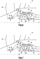
- the input housing 32 being positioned forward relative to the planet carrier 43, the junction between the planet carrier 43 and the input housing 32 forms, as illustrated in the figure 6 , a return elbow 33.
- the return elbow may have a portion extending axially forward and radially outward.
- the return elbow 33 may form a locally more flexible part capable of accommodating axial movements of the epicyclic gear train 40 relative to the input casing 32.
- the part connecting the planet carrier 43 to the input casing 32 is perforated at the level of the planets 41 makes it possible to accommodate radial movements of the epicyclic gear train 40 relative to the input casing 32.
- the casing 30 may be free of meanders. This makes it possible to reduce the length and size of the engine.
- the third bearing 54 supports the LP compressor 50 relative to the casing 30, here relative to the inlet casing 32.
- the fourth bearing 56 in this case the roller bearing, is arranged between the shaft of the LP compressor 52 and the LP turbine shaft 92.
- the fourth bearing 56 therefore forms an intershaft bearing.
- the integration of an intershaft bearing makes it possible to limit the size of stator parts under the LP compressor 50.
- this drive may be direct, i.e. in particular without an intermediate transmission stage.
Landscapes
- Engineering & Computer Science (AREA)
- General Engineering & Computer Science (AREA)
- Chemical & Material Sciences (AREA)
- Combustion & Propulsion (AREA)
- Mechanical Engineering (AREA)
- Structures Of Non-Positive Displacement Pumps (AREA)
- Retarders (AREA)
- General Details Of Gearings (AREA)
Description
- Le présent exposé concerne le domaine des aéronefs, et plus particulièrement une turbomachine pouvant être utilisée pour la propulsion aéronautique.
- Les turbomachines utilisées pour la propulsion des aéronefs, par exemple les turboréacteurs, comprennent généralement un carter dans lequel sont logés une soufflante fournissant l'essentiel de la poussée, un compresseur et une turbine. Le compresseur fournit de l'air comprimé à une chambre de combustion et les gaz de combustion produits dans ladite chambre mettent en mouvement la turbine, qui entraîne à son tour la soufflante.
- Pour maximiser le rendement de la turbine, il est souhaitable qu'elle tourne le plus vite possible. Inversement, la vitesse de la soufflante est limitée par la vitesse de rotation en tête de pale, qui doit le plus souvent rester inférieure à la vitesse du son.
- Pour pallier ce problème, on connaît des turbomachines munies d'un réducteur placé dans la chaîne de transmission entre la turbine et la soufflante, comme l'illustrent par exemple les documents
US 4,251,987 etUS 2007/087892 . Un réducteur permet de faire tourner la turbine et la soufflante à des vitesses différentes. - Il existe néanmoins encore un besoin d'amélioration pour des turbomachines pour aéronef.
- A cet effet, le présent exposé concerne une turbomachine pour aéronef selon la revendication 1, la turbomachine comprenant un carter, une soufflante, un compresseur et une turbine, et un train épicycloïdal comprenant une entrée entraînée en rotation par la turbine, un premier étage de sortie configuré pour entraîner en rotation le compresseur et un deuxième étage de sortie couplé au premier étage de sortie et configuré pour entraîner en rotation la soufflante, le compresseur étant entraîné en rotation par la couronne du premier étage de sortie.
- Le carter désigne une partie globalement fixe de la turbomachine, la soufflante, le compresseur et la turbine comprenant des roues aubagées configurées pour tourner par rapport au carter. Le carter comprend un carter d'entrée entre la soufflante et le compresseur.
- Dans le présent exposé, on appelle axe de la turbomachine, son axe de symétrie ou quasi-symétrie, qui forme l'axe de rotation au moins de la turbine, et généralement aussi du compresseur et de la soufflante. La direction axiale correspond à la direction de l'axe de la turbomachine et une direction radiale est une direction perpendiculaire à cet axe et coupant cet axe. De même, un plan axial est un plan contenant l'axe de la turbomachine et un plan radial est un plan perpendiculaire à cet axe. Une circonférence s'entend comme un cercle appartenant à un plan radial et dont le centre appartient à l'axe de la turbomachine. Une direction tangentielle ou circonférentielle est une direction tangente à une circonférence ; elle est perpendiculaire à l'axe de la turbomachine mais ne passe pas par l'axe.
- Sauf précision contraire, les adjectifs avant et arrière sont utilisés en référence à la direction axiale étant entendu que l'entrée de la turbomachine est située du côté avant de la turbomachine, tandis que sa sortie est située du côté arrière. Les adjectifs amont et aval sont utilisés en référence au sens d'écoulement normal des gaz dans la turbomachine.
- Enfin, sauf précision contraire, les adjectifs intérieur (interne) et extérieur (externe) sont utilisés en référence à une direction radiale de sorte que la partie intérieure d'un élément est, suivant une direction radiale, plus proche de l'axe de la turbomachine que la partie extérieure du même élément.
- Un train épicycloïdal comprend un planétaire intérieur, aussi connu sous le nom de pignon central ou soleil et appelé simplement « planétaire » par la suite, un ou plusieurs satellites en révolution autour du planétaire et une couronne, parfois appelée planétaire extérieur, entourant le ou les satellites. Par la suite, sans perte de généralité, on parlera indifféremment d'un ou plusieurs satellites. Les satellites peuvent être montés rotatifs sur un porte-satellite, le porte-satellite étant configuré pour synchroniser la révolution des différents satellites par rapport au planétaire ou à la couronne.
- Sauf mention contraire explicite ou ressortant du contexte, par la suite, les références aux rayons et diamètres des roues s'entendent comme des références aux rayons et diamètres primitifs, respectivement. Le cercle primitif est tel que les cercles primitifs de deux roues engrenées ont la même vitesse tangentielle.
- La liaison mécanique entre les composants du train épicycloïdal (planétaire, satellites, porte-satellite, couronne) et les organes de la turbomachine (soufflante, compresseur, turbine) peut être assurée au moyen d'arbres solidaires en rotation desdits organes.
- Grâce au fait que la soufflante et le compresseur sont entraînés en rotation par deux sorties différentes du train épicycloïdal, il est possible de faire tourner non seulement la soufflante et la turbine, mais aussi le compresseur et la turbine, à des vitesses différentes. Plusieurs facteurs imposent d'augmenter le rayon du compresseur : l'intégration du train épicycloïdal, prévu pour la soufflante, à proximité du compresseur, mais aussi des contraintes d'aérodynamique de veine et l'intégration d'autres éléments de la turbomachine tels que paliers, arbres, tourillons et ventilation. Ce faisant, la vitesse de rotation du compresseur doit être réduite pour éviter que la vitesse tangentielle en tête de pale du compresseur ne dépasse les limites applicables. L'utilisation de deux sorties différentes permet donc de limiter le régime du compresseur tout en ayant un régime le plus élevé possible pour la turbine et un régime relativement faible pour la soufflante, en vue par exemple d'augmenter le rayon de la soufflante.
- Le deuxième étage de sortie est couplé au premier étage de sortie, ce qui signifie qu'il existe une connexion fonctionnelle entre le premier étage de sortie et le deuxième étage de sortie, permettant la transmission d'un couple entre ces deux étages de sortie. Grâce au fait que le train épicycloïdal est un train épicycloïdal multi-étages comprenant au moins un premier étage de sortie et un deuxième étage de sortie couplés l'un à l'autre, la turbomachine peut conserver une bonne compacité malgré un rapport de réduction turbine-soufflante potentiellement très élevé (typiquement supérieur à 5). Par comparaison, un train épicycloïdal à simple étage ayant un rapport de réduction comparable serait radialement encombrant et imposerait soit de prévoir un déport radialement vers l'extérieur, parfois appelé « col de cygne », et un allongement axial de la turbomachine, soit de placer le compresseur à rayon plus élevé et donc de limiter sa vitesse, ce qui affecte son rendement.
- Enfin, grâce au fait que le compresseur est entraîné en rotation par la couronne du premier étage de sortie, on peut obtenir un rapport de réduction entre le compresseur et la turbine proportionnel au rapport des rayons du planétaire et de la couronne du premier étage de sortie, tout en conservant une sortie plus lente sur la couronne du deuxième étage. Par différence, si le compresseur était entraîné par le planétaire du premier étage de sortie, l'entrée entraînée par la turbine devrait être le planétaire intérieur du deuxième étage. Le deuxième étage de sortie entraînant la soufflante en rotation, cette configuration ne laisserait plus qu'un seul étage pour effectuer le rapport de réduction entre la soufflante et la turbine : cela ramènerait donc l'architecture aux problèmes d'encombrement exposés plus haut. De plus, le fait de ne pas utiliser les planétaires internes de tous les étages facilite l'intégration de butées internes au train épicycloïdal afin de reprendre les efforts internes lorsqu'on utilise des dentures chevrons.
- Ensemble, ces caractéristiques améliorent l'intégration du compresseur et le rendement global de la turbomachine.
- Dans certains modes de réalisation, la soufflante est entraînée en rotation par la couronne du deuxième étage de sortie. Ainsi, on tire parti des deux étages du train épicycloïdal afin d'obtenir des rapports de réduction relativement élevés avec un encombrement radial raisonnable.
- Dans certains modes de réalisation, le train épicycloïdal comprend au moins un satellite comprenant une première roue et une deuxième roue solidaires en rotation l'une de l'autre, la première roue appartenant au premier étage de sortie et s'engrenant avec la couronne du premier étage de sortie et la deuxième roue appartenant au deuxième étage de sortie. La première roue et la deuxième roue peuvent appartenir à une même pièce formant le satellite.
- Le cas échéant, la deuxième roue peut s'engrener avec la couronne du deuxième étage de sortie.
- Dans certains modes de réalisation, le rapport entre le diamètre de la première roue de sortie et le diamètre de la deuxième roue de sortie est compris entre 0,5 et 10.
- Dans certains modes de réalisation, le train épicycloïdal comprend un porte-satellite fixe par rapport au carter. Le porte-satellite étant fixe, la couronne de chaque étage de sortie et le planétaire sont entraînés en rotation.
- Ainsi, dans certains modes de réalisation, l'entrée du train épicycloïdal comprend un planétaire du train épicycloïdal. En d'autres termes, la turbine est configurée pour entraîner en rotation le planétaire du train épicycloïdal. Ce choix permet d'obtenir une réduction de vitesse de rotation tout en limitant la complexité et l'encombrement.
- Dans certains modes de réalisation, le compresseur est soutenu par rapport au carter par au moins un palier. Par exemple, le palier peut être un roulement à billes ou un palier à rouleaux. Il peut en outre être prévu plusieurs paliers, au moins l'un, plusieurs ou tous les paliers étant agencés entre le compresseur et le carter.
- Dans certains modes de réalisation, la turbomachine comprend en outre un palier agencé entre un arbre du compresseur et un arbre de la turbine. Un tel palier, installé entre deux parties tournantes, est généralement appelé palier interarbre. Par exemple, le palier interarbre peut être un palier à rouleaux. Il peut en outre être prévu plusieurs paliers, au moins l'un, plusieurs ou tous les paliers étant agencés entre un arbre du compresseur et un arbre de la turbine. Un palier interarbre ainsi agencé permet de limiter l'encombrement des parties statoriques sous le compresseur.
- Dans certains modes de réalisation, trois éléments parmi un arbre de soufflante, un arbre de compresseur, un arbre de turbine et le carter comprennent une portion localement plus souple apte à accommoder des déplacements axiaux desdits éléments. La portion est dite localement plus souple au sens où elle présente localement une rigidité moindre que les portions environnantes. Ladite portion forme donc une zone de déformation préférentielle et facilitée pour accommoder les déplacements. En effet, le train épicycloïdal étant hyperstatique, les déplacements relatifs de l'entrée et des étages de sortie, notamment dans la direction axiale, ont tendance à provoquer des surcharges dans les composants du train épicycloïdal. Les portions localement plus souples respectives permettent de diminuer, sinon d'éviter ces surcharges. Le quatrième élément parmi les éléments précités peut être relativement plus rigide que les portions localement plus souples. Le composant du train épicycloïdal couplé à cet élément est dit « maître » dans la mesure où il impose ses déplacements aux autres composants du train épicycloïdal, dits « esclaves » et qui, par le biais des portions localement plus souples, n'entraînent pas de déplacement des organes de turbomachine correspondants.
- Dans certains modes de réalisation, ladite portion présente des méandres en section axiale. La section axiale est une section dans un plan axial tel que défini précédemment. Les méandres définissent une forme non purement axiale, par exemple ayant une composante radiale non nulle. Les méandres peuvent comprendre des sinuosités, des formes en ligne brisée, en zigzag, en chicane, etc.
- Dans certains modes de réalisation, ladite soufflante est l'unique soufflante de la turbomachine. La turbomachine ne comprend donc pas d'autre soufflante.
- Dans certains modes de réalisation, ledit compresseur est un compresseur basse-pression et la turbomachine comprend en outre un compresseur haute-pression en aval du compresseur basse-pression, le carter comprenant un carter inter-compresseurs entre le compresseur basse-pression et le compresseur haute-pression.
- Dans certains modes de réalisation, un arbre de soufflante est soutenu par rapport au carter d'entrée par au moins un palier. Optionnellement, l'arbre de soufflante est soutenu par rapport au carter d'entrée par au moins deux paliers. Optionnellement, ces deux paliers comprennent au moins un palier à billes et au moins un palier à rouleaux.
- Par ailleurs, le présent exposé concerne également une turbomachine pour aéronef, comprenant un carter, une soufflante, un compresseur et une turbine, et un train épicycloïdal comprenant une entrée entraînée en rotation par la turbine, un premier étage de sortie et un deuxième étage de sortie couplé au premier étage de sortie, dans lequel la turbine est configurée pour entraîner en rotation un planétaire du premier étage de sortie, la soufflante est entraînée en rotation par la couronne du deuxième étage de sortie, et le compresseur est entraîné en rotation par la couronne du premier étage de sortie ou par le planétaire du deuxième étage de sortie.
- D'autres caractéristiques et avantages de l'objet du présent exposé ressortiront de la description suivante de modes de réalisation, donnés à titre d'exemples non limitatifs, en référence aux figures annexées.
- [
Fig. 1 ] Lafigure 1 est une vue d'ensemble schématique d'une turbomachine selon un mode de réalisation. - [
Fig. 2 ] Lafigure 2 est un schéma d'un train épicycloïdal selon un mode de réalisation. - [
Fig. 3 ] Lafigure 3 est une partie d'une coupe longitudinale de la turbomachine selon un premier mode de réalisation. - [
Fig. 4 ] Lafigure 4 est une partie d'une coupe longitudinale de la turbomachine selon un deuxième mode de réalisation. - [
Fig. 5 ] Lafigure 5 est une vue en coupe longitudinale et en perspective d'une partie de la turbomachine selon le deuxième mode de réalisation. - [
Fig. 6 ] Lafigure 6 est une partie d'une coupe longitudinale de la turbomachine selon un troisième mode de réalisation. - [
Fig. 7 ] Lafigure 7 est une partie d'une coupe longitudinale de la turbomachine selon un quatrième mode de réalisation. - Une turbomachine 10 pour aéronef selon un mode de réalisation est représentée schématiquement sur la
figure 1 , en demi-coupe longitudinale. En l'occurrence, la turbomachine 10 est un turboréacteur à double corps et double flux. En effet, la turbomachine 10 comprend une soufflante 20, de préférence unique, un carter interne 30 disposé en aval de la soufflante 20 et séparant une veine primaire 12 d'une veine secondaire 14. Un compresseur basse pression (compresseur BP) 50, un compresseur haute pression (compresseur HP) 60, une chambre de combustion 70, une turbine haute pression (turbine HP) 80 et une turbine basse pression (turbine BP) 90 sont agencés dans la veine primaire 12, de l'amont vers l'aval. Du fait que la turbomachine 10 est à double corps, elle comporte deux ensemble tournants cinématiquement indépendants, à savoir d'une part un corps haute pression (corps HP), comprenant le compresseur HP 60 et la turbine HP 80, et d'autre part un corps basse pression (corps BP) comprenant le compresseur BP 50 et la turbine BP 80. Chaque compresseur 50, 60 est entraîné directement ou indirectement par la turbine 80, 90 du corps correspondant, les turbines 80, 90 étant mises en mouvement par les gaz de combustion issus de la chambre de combustion 70. - Toutefois, le présent exposé est transposable au cas d'une turbomachine à simple corps. L'unique corps aurait la fonction du corps HP pour le fonctionnement de la turbomachine, mais son rôle par rapport au train épicycloïdal décrit ci-après serait celui du corps BP.
- Le carter de la turbomachine comprend en outre, dans ce mode de réalisation, un carter d'entrée 32 entre la soufflante 20 et le compresseur BP 50, un carter inter-compresseurs 34 entre le compresseur BP 50 et le compresseur HP 60, un carter inter-turbines 36 entre la turbine HP 80 et la turbine BP 90, et un carter arrière de turbine 38 (de l'anglais turbine rear frame) en aval de la turbine BP 90. Les éléments de carter sont fixes dans le référentiel de l'avion, et les parties tournantes, à savoir les roues aubagées mobiles de la soufflante 20, des compresseurs 50, 60 et des turbines 80, 90, tournent par rapport au carter.
- La rotation de la turbine HP 80 entraîne le compresseur HP 60 via un arbre HP 82. Le compresseur HP 60 et la turbine HP 80 sont donc cinématiquement dépendants l'un de l'autre et, en particulier ici, tournent à la même vitesse. L'arbre HP 82 peut être soutenu par rapport au carter par au moins un palier, en l'occurrence un premier palier 84, typiquement un roulement à billes, par rapport au carter inter-compresseurs 34 et un deuxième palier 86, typiquement un palier à rouleaux, par rapport au carter inter-turbines 36.
- Par ailleurs, dans ce mode de réalisation, la turbine BP 90 entraîne en rotation le compresseur BP 50. La turbine BP 90 entraîne également en rotation la soufflante 20. Plus précisément, la turbomachine 10 comprend une transmission, ici un train épicycloïdal 40, couplée à la turbine BP 90 via un arbre de turbine BP 92. Dans ce mode de réalisation, l'arbre de turbine BP 92 est agencé coaxialement à l'intérieur de l'arbre HP 82. Des paliers 94, 96 peuvent être prévus pour soutenir l'arbre de turbine BP 92.
- Par ailleurs, comme illustré sur la
figure 1 , le train épicycloïdal 40 est couplé en outre à la soufflante 20 et au compresseur BP 50 afin de modifier le rapport de transmission de vitesse de rotation entre la turbine BP 90 et d'une part la soufflante 20, d'autre part le compresseur BP 50. Le train épicycloïdal 40 forme donc un réducteur entre la turbine BP 90 et d'une part la soufflante 20, d'autre part le compresseur BP 50. - En d'autres termes, comme illustré sur la
figure 1 , le train épicycloïdal 40 comprend une entrée entraînée en rotation par la turbine BP 90, un premier étage de sortie configuré pour entraîner en rotation le compresseur BP 50 et un deuxième étage de sortie couplé au premier étage de sortie et configuré pour entraîner en rotation la soufflante 20. - La structure du train épicycloïdal 40 est représentée en détail sur le schéma de la
figure 2 . - Le train épicycloïdal 40 comprend un planétaire 49. Dans ce mode de réalisation, le planétaire 49 est entraîné en rotation par la turbine BP 90. Plus précisément, le planétaire 49 peut être entraîné en rotation, voire solidaire en rotation, de l'arbre de turbine BP 92. Ainsi, dans ce mode de réalisation, l'entrée du train épicycloïdal 40 comprend le planétaire 49.
- Le planétaire 49 s'engrène avec au moins un satellite 41. Le satellite 41 tourne sur lui-même. Le satellite 41 suit un mouvement de révolution autour du planétaire 49 mais, le planétaire 49 tournant lui-même, le satellite 41 peut avoir un axe de rotation fixe dans le référentiel de la turbomachine 10, comme cela sera illustré par la suite.
- Le satellite 41 comprend une première roue 41a et une deuxième roue 41b. La première roue 41a et la deuxième roue 41b sont couplées l'une à l'autre, et plus précisément ici solidaires en rotation l'une de l'autre. La première roue 41a appartient au premier étage de sortie 47 du train épicycloïdal 40. La deuxième roue 41b appartient au deuxième étage de sortie 48 du train épicycloïdal 40.
- Le satellite 41 est monté rotatif sur un porte-satellite 43. Le porte-satellite 43 est ici fixe par rapport au carter 30, par exemple, comme schématisé sur la
figure 1 , fixé sur le carter inter-compresseurs 34. - Le train épicycloïdal 40 comprend par ailleurs deux couronnes 42, 45. La première couronne 45, ou couronne du premier étage de sortie 47, s'engrène avec le satellite 41, plus particulièrement sa première roue 41a. Par ailleurs, la première couronne 45 est configurée pour entraîner en rotation le compresseur BP 50. Plus précisément, la première couronne 45 peut entraîner en rotation, voire être solidaire en rotation d'un arbre de compresseur BP 52 lui-même solidaire en rotation du compresseur BP 50.
- La deuxième couronne 42, ou couronne du deuxième étage de sortie 48, s'engrène avec le satellite 41, plus particulièrement sa deuxième roue 41b. Par ailleurs, la deuxième couronne 42 est configurée pour entraîner en rotation la soufflante 20. Plus précisément, la deuxième couronne 42 peut entraîner en rotation, voire être solidaire en rotation d'un arbre de soufflante 22 lui-même solidaire en rotation de la soufflante 20.
- L'arbre de soufflante 22 peut être soutenu par rapport au carter 30, notamment par rapport au carter d'entrée 32, par au moins un palier. En l'espèce, comme illustré sur la
figure 1 , l'au moins un palier peut comprendre au moins deux paliers, à savoir au moins un palier à rouleaux 24 et au moins un roulement à billes 26. - Le porte-satellite 43 étant fixe par rapport au carter, la rotation du planétaire 49 se transmet aux couronnes 42, 45 via le satellite 41.
- Ainsi, en fonctionnement, la rotation de la turbine BP 90 est transmise, via l'arbre de turbine BP 92, au planétaire 49. La rotation du planétaire 49 entraîne en rotation le satellite 41. Le premier étage de sortie 47 entraîne en rotation le compresseur BP 50 via la première roue 41a, la première couronne 45 et l'arbre de compresseur BP 52. Le deuxième étage de sortie 48 entraîne en rotation la soufflante 20 via la deuxième roue 41b, la deuxième couronne 42 et l'arbre de soufflante 20.
- En notant Ri le rayon fonctionnel d'un composant i par rapport à son axe de rotation (par exemple R42 pour le rayon interne de la deuxième couronne 42) et Ωi la vitesse de rotation du composant i, on a les relations R49Ω49 =R41aΩ41, R41aΩ41 =R45 Ω45, et R41b Ω41 =R42 Ω42, d'où l'on tire que la vitesse de rotation de la première couronne 45, et donc de l'arbre de compresseur BP 52, est égale à Ω45 =(R49/R45)Ω49, et que la vitesse de rotation de la deuxième couronne 42, et donc de l'arbre de soufflante 22, est égale à Ω42 =(R49/R41a)(R41b/R42)Ω49.
- Pour le dimensionnement des vitesses relatives de la soufflante 20 et du compresseur BP, le satellite 41 peut être conçu de sorte que le rapport entre le diamètre de la première roue de sortie et le diamètre de la deuxième roue de sortie soit compris entre 0,5 et 10.
- La configuration du train épicycloïdal 40 étant donnée comme ci-dessus, sa réalisation détaillée peut être conçue par l'homme du métier selon ses connaissances générales.
- En outre, bien qu'on ait décrit ici un train épicycloïdal 40 dont le planétaire 49 forme l'entrée et les couronnes 42, 45 forment les sorties, il est possible de choisir autrement les composants du train épicycloïdal 40 formant l'entrée et les sorties, par exemple selon les rapports de réduction de vitesse souhaités. Ces changements peuvent être réalisés quitte, éventuellement, à ajouter une roue supplémentaire au satellite 41 pour offrir davantage de liberté de conception.
- L'intégration pratique du train épicycloïdal 40 dans une turbomachine est illustrée, selon un premier mode de réalisation, sur la
figure 3 . La présence du train épicycloïdal 40 et d'arbre distincts pour la turbine BP 90 et le compresseur BP 50 impose en effet de revoir l'architecture de la turbomachine, en particulier l'emplacement des paliers. - Ainsi, dans ce premier mode de réalisation, la turbomachine 10 comprend au moins un palier configuré pour soutenir le compresseur BP 50 par rapport au carter 30. En l'occurrence, deux paliers 54, 56 sont prévus. Les paliers 54, 56 sont ici agencés entre le carter inter-compresseurs 34 et l'arbre de compresseur BP 52. Plus précisément, les paliers 54, 56 sont agencés sur la partie du carter 30 sur laquelle est fixée le porte-satellite 43.
- Dans ce mode de réalisation, le palier 54 (troisième palier) peut-être un roulement à billes, tandis que le palier 56 (quatrième palier) peut-être un palier à rouleaux. Toutefois, les paliers 54, 56 peuvent être interchangés et/ou être d'un autre type, même s'il est souhaitable qu'au maximum l'un des paliers soit un roulement à billes, de façon à éviter un montage hyperstatique des paliers.
- La présence de deux paliers assure le maintien et empêche le rotulage du compresseur BP 50, c'est-à-dire le risque qu'un palier unique se comporte comme une liaison rotule en cas de charge radiale désaxée trop importante, ce qui aurait pour conséquence de ne plus assurer la coaxialité du rotor de compresseur BP 50 avec son stator, et donc de l'endommager.
- Par ailleurs, pour éviter un montage hyperstatique du train épicycloïdal 40, on peut prévoir que trois éléments parmi l'arbre de soufflante 22, l'arbre de compresseur BP 52, l'arbre de turbine BP 92 et le carter 30 (en l'espèce le carter inter-compresseurs 34) comprennent une portion localement plus souple apte à accommoder des déplacements axiaux desdits éléments. En l'occurrence, l'arbre de soufflante 22 est conçu relativement rigide ou raide, tandis que des portions localement souples 34a, 52a, 92a sont prévues respectivement sur le carter inter-compresseurs 34, l'arbre de compresseur BP 52 et l'arbre de turbine BP 92.
- Comme illustré sur la
figure 3 , lesdites portions localement souples sont prévues sur les arbres entre le train épicycloïdal 40 et les paliers soutenant les organes de la turbomachine correspondants, par exemple les paliers 54, 56. Ainsi, les déplacements axiaux et/ou radiaux relatifs au sein du train épicycloïdal 40, voire les déplacements axiaux et/ou radiaux de l'arbre de soufflante 22, sont absorbés par les portions localement souples 34a, 52a, 92a et ne perturbent pas le fonctionnement des paliers ni, plus généralement, la dynamique de la turbomachine 10. - Dans ce mode de réalisation, au moins une desdites portions localement souples 34a, 52a, 92a, ici toutes, présentent des méandres en section axiale. Les méandres sont ici formés par une succession axiale de sections radialement croissantes et décroissantes. Les méandres apportent de la souplesse sans compromettre la tenue mécanique de la turbomachine 10.
- Lorsqu'un élément est soutenu à la fois par un roulement à billes et par un palier à rouleaux, il est possible de prévoir, comme l'illustre la
figure 1 , que le roulement à billes soit plus proche du train épicycloïdal 40 que le palier à rouleaux, afin de minimiser les jeux axiaux à l'intérieur du train épicycloïdal 40. Cette propriété peut être prévue indépendamment pour chaque élément. Il s'ensuit un support optimisé du train épicycloïdal. - Les
figures 4 à7 présentent la turbomachine dans d'autres modes de réalisation. Sur ces figures, les éléments correspondant ou identiques à ceux du premier mode de réalisation recevront le même signe de référence et ne seront pas décrits à nouveau. - Dans le deuxième mode de réalisation, illustré sur les
figures 4 et5 , qui présente une variante du premier mode de réalisation, les paliers 54, 56 sont agencés entre l'arbre de compresseur BP 52 et une partie du carter inter-compresseurs 34 indépendante de la partie sur laquelle est fixé le porte-satellite 43. Cette configuration permet de refermer les jeux des paliers 54, 56, et plus particulièrement du roulement à billes 54 : en effet, le rotor est situé radialement à l'intérieur du stator. Sous effort centrifuge, le jeu rotor/stator se referme. - La
figure 5 illustre plus particulièrement l'agencement des satellites 41, ici au nombre de quatre (dont trois sont visibles sur la figure), sur le porte-satellites 43 et le maintien du porte-satellites 43 par rapport au carter inter-compresseurs 34. Sur la vue représentée, le carter inter-compresseurs 34 et le porte-satellites 43 sont venus de matière, mais en alternative, il est possible de prévoir une fixation entre le carter inter-compresseurs 34 et le porte-satellite 43, par exemple pour faciliter le montage du train épicycloïdal 40. - Dans le troisième mode de réalisation, illustré sur la
figure 6 , les paliers 54, 56 sont agencés entre l'arbre de compresseur BP 52 et le carter inter-compresseurs 34. Toutefois, le porte-satellite 43 est quant à lui fixé non sur le carter inter-compresseurs 34, mais sur le carter d'entrée 32. Pour ce faire, par exemple, le support du porte-satellites 43 passe entre deux satellites 41 consécutifs. Cela libère de la place pour positionner les paliers 54, 56 plus près de l'axe de rotation X, ce qui les sollicite moins mécaniquement. De plus, cela permet de libérer de l'espace sous le compresseur BP 50, ce qui facilite l'intégration sous le compresseur BP 50 et permet d'abaisser les alésages, réduisant ainsi la masse des disques. - En outre, le carter d'entrée 32 étant positionné vers l'avant par rapport au porte-satellite 43, la jonction entre le porte-satellite 43 et le carter d'entrée 32 forme, comme illustré sur la
figure 6 , un coude de retour 33. Le coude de retour peut présenter une portion s'étendant axialement vers l'avant et radialement vers l'extérieur. Le coude de retour 33 peut former une partie localement plus souple apte à accommoder des déplacements axiaux du train épicycloïdal 40 par rapport au carter d'entrée 32. En outre, le fait que le la pièce liant le porte-satellites 43 au carter d'entrée 32 soit ajourée au niveau des satellites 41 permet d'accommoder des déplacements radiaux du train épicycloïdal 40 par rapport au carter d'entrée 32. Ainsi, dans ces modes de réalisation, le carter 30 peut être dépourvu de méandres. Cela permet de réduire la longueur et l'encombrement du moteur. - Dans le quatrième mode de réalisation, illustré sur la
figure 7 , qui présente une variante du troisième mode de réalisation, le troisième palier 54 soutient le compresseur BP 50 par rapport au carter 30, ici par rapport au carter d'entrée 32. Le quatrième palier 56, en l'espèce le palier à rouleaux, est agencé entre l'arbre du compresseur BP 52 et l'arbre de turbine BP 92. Le quatrième palier 56 forme donc un palier interarbre. Comme indiqué précédemment, l'intégration d'un palier interarbre permet de limiter l'encombrement de pièces de stator sous le compresseur BP 50. - Dans l'ensemble du présent exposé, lorsqu'il est question d'entraînement, cet entraînement peut être direct, c'est-à-dire en particulier sans étage de transmission intermédiaire.
- Bien que la présente description se réfère à des exemples de réalisation spécifiques, des modifications peuvent être apportées à ces exemples sans sortir de la portée générale de l'invention telle que définie par les revendications. Par conséquent, la description et les dessins doivent être considérés dans un sens illustratif plutôt que restrictif.
Claims (13)
- Turbomachine (10) pour aéronef, comprenant un carter (30), une soufflante (20), un compresseur (50), une turbine (90), le carter (30) comprenant un carter d'entrée (32) entre la soufflante (20) et le compresseur (50), la turbomachine (10) comprenant en outre un train épicycloïdal (40) comprenant une entrée entraînée en rotation par la turbine (90), un premier étage de sortie (47) configuré pour entraîner en rotation le compresseur (50) et un deuxième étage de sortie (48) couplé au premier étage de sortie (47) et configuré pour entraîner en rotation la soufflante (20);
caractérisée en ce que le compresseur est entraîné en rotation par une première couronne (45), la première couronne (45) étant la couronne du premier étage de sortie (47). - Turbomachine selon la revendication 1, dans laquelle la soufflante (20) est entraînée en rotation par une deuxième couronne (42), la deuxième couronne (42) étant la couronne du deuxième étage de sortie (48).
- Turbomachine selon la revendication 1 ou 2, dans laquelle le train épicycloïdal (40) comprend au moins un satellite (41) comprenant une première roue (41a) et une deuxième roue (41b) solidaires en rotation l'une de l'autre, la première roue (41a) appartenant au premier étage de sortie (47) et s'engrenant avec la couronne (45) du premier étage de sortie (47) et la deuxième roue (41b) appartenant au deuxième étage de sortie (48).
- Turbomachine selon la revendication 3, dans laquelle le rapport entre le diamètre de la première roue de sortie (41a) et le diamètre de la deuxième roue de sortie (41b) est compris entre 0,5 et 10.
- Turbomachine selon l'une quelconque des revendications 1 à 4, dans laquelle le train épicycloïdal (40) comprend un porte-satellite (43) fixe par rapport au carter (30).
- Turbomachine selon l'une quelconque des revendications 1 à 5, dans laquelle l'entrée comprend un planétaire (49) du train épicycloïdal (40).
- Turbomachine selon l'une quelconque des revendications 1 à 6, dans laquelle le compresseur (50) est soutenu par rapport au carter par au moins un palier (54).
- Turbomachine selon l'une quelconque des revendications 1 à 7, comprenant en outre un palier (56) agencé entre un arbre (52) du compresseur (50) et un arbre (92) de la turbine (90).
- Turbomachine selon l'une quelconque des revendications 1 à 8, dans lequel trois éléments parmi un arbre de soufflante (22), un arbre de compresseur (52), un arbre de turbine (92) et le carter (30) comprennent une portion localement plus souple (34a, 52a, 92a) apte à accommoder des déplacements axiaux desdits éléments.
- Turbomachine selon la revendication 9, dans laquelle ladite portion (34a, 52a, 92a) présente des méandres en section axiale.
- Turbomachine selon l'une quelconque des revendications 1 à 10, dans laquelle ladite soufflante (20) est l'unique soufflante de la turbomachine.
- Turbomachine selon l'une quelconque des revendications 1 à 11, dans laquelle ledit compresseur (50) est un compresseur basse-pression et la turbomachine comprend en outre un compresseur haute-pression (60) en aval du compresseur basse-pression (50), le carter (30) comprenant un carter inter-compresseurs (34) entre le compresseur basse-pression (50) et le compresseur haute-pression (60).
- Turbomachine selon l'une quelconque des revendications 1 à 12, dans laquelle un arbre de soufflante (22) est soutenu par rapport au carter d'entrée (32) par au moins un palier, de préférence au moins deux paliers, de préférence encore au moins un palier à billes et un palier à rouleaux.
Applications Claiming Priority (2)
| Application Number | Priority Date | Filing Date | Title |
|---|---|---|---|
| FR2003020A FR3108683B1 (fr) | 2020-03-27 | 2020-03-27 | Turbomachine pour aéronef |
| PCT/FR2021/050521 WO2021191569A2 (fr) | 2020-03-27 | 2021-03-25 | Turbomachine pour aeronef |
Publications (2)
| Publication Number | Publication Date |
|---|---|
| EP4127437A2 EP4127437A2 (fr) | 2023-02-08 |
| EP4127437B1 true EP4127437B1 (fr) | 2025-01-29 |
Family
ID=70614281
Family Applications (1)
| Application Number | Title | Priority Date | Filing Date |
|---|---|---|---|
| EP21732377.3A Active EP4127437B1 (fr) | 2020-03-27 | 2021-03-25 | Turbomachine pour aéronef |
Country Status (5)
| Country | Link |
|---|---|
| US (1) | US11994073B2 (fr) |
| EP (1) | EP4127437B1 (fr) |
| CN (1) | CN115698483A (fr) |
| FR (1) | FR3108683B1 (fr) |
| WO (1) | WO2021191569A2 (fr) |
Citations (1)
| Publication number | Priority date | Publication date | Assignee | Title |
|---|---|---|---|---|
| EP1921290B1 (fr) * | 2006-10-31 | 2016-06-01 | General Electric Company | Assemblage de moteur de réacteur à double flux |
Family Cites Families (6)
| Publication number | Priority date | Publication date | Assignee | Title |
|---|---|---|---|---|
| US4251987A (en) * | 1979-08-22 | 1981-02-24 | General Electric Company | Differential geared engine |
| US6223616B1 (en) * | 1999-12-22 | 2001-05-01 | United Technologies Corporation | Star gear system with lubrication circuit and lubrication method therefor |
| US7752836B2 (en) * | 2005-10-19 | 2010-07-13 | General Electric Company | Gas turbine assembly and methods of assembling same |
| FR2972765B1 (fr) * | 2011-03-17 | 2013-04-05 | Messier Dowty | Procede d'optimisation de vitesse de soufflante de turboreacteur double-corps et architecture de mise en oeuvre. |
| US8572943B1 (en) * | 2012-05-31 | 2013-11-05 | United Technologies Corporation | Fundamental gear system architecture |
| US8678743B1 (en) * | 2013-02-04 | 2014-03-25 | United Technologies Corporation | Method for setting a gear ratio of a fan drive gear system of a gas turbine engine |
-
2020
- 2020-03-27 FR FR2003020A patent/FR3108683B1/fr active Active
-
2021
- 2021-03-25 WO PCT/FR2021/050521 patent/WO2021191569A2/fr not_active Ceased
- 2021-03-25 US US17/906,790 patent/US11994073B2/en active Active
- 2021-03-25 EP EP21732377.3A patent/EP4127437B1/fr active Active
- 2021-03-25 CN CN202180023503.9A patent/CN115698483A/zh active Pending
Patent Citations (1)
| Publication number | Priority date | Publication date | Assignee | Title |
|---|---|---|---|---|
| EP1921290B1 (fr) * | 2006-10-31 | 2016-06-01 | General Electric Company | Assemblage de moteur de réacteur à double flux |
Also Published As
| Publication number | Publication date |
|---|---|
| WO2021191569A2 (fr) | 2021-09-30 |
| EP4127437A2 (fr) | 2023-02-08 |
| FR3108683B1 (fr) | 2022-11-25 |
| FR3108683A1 (fr) | 2021-10-01 |
| CN115698483A (zh) | 2023-02-03 |
| US20230145716A1 (en) | 2023-05-11 |
| WO2021191569A3 (fr) | 2022-03-10 |
| US11994073B2 (en) | 2024-05-28 |
Similar Documents
| Publication | Publication Date | Title |
|---|---|---|
| EP3922886B1 (fr) | Reducteur mecanique de turbomachine d'aeronef | |
| EP2396525B1 (fr) | Système d'hélices contrarotatives à encombrement réduit | |
| EP3995681B1 (fr) | Reducteur mecanique de turbomachine d'aeronef | |
| WO2020058652A1 (fr) | Turboréacteur comprenant un dispositif d'apport de puissance | |
| EP3705705A1 (fr) | Réducteur mécanique de turbomachine d'aéronef | |
| EP4151846B1 (fr) | Turbomachine d'aeronef | |
| EP4073366A1 (fr) | Système propulsif aéronautique à faible débit de fuite et rendement propulsif amélioré | |
| EP3853456B1 (fr) | Turboréacteur à réducteur | |
| EP4073371B1 (fr) | Système propulsif aéronautique à faible débit de fuite et rendement propulsif amélioré | |
| EP4033086B1 (fr) | Turbomachine d'aeronef a triple flux equipe d'un module de transmission de puissance | |
| EP4127437B1 (fr) | Turbomachine pour aéronef | |
| EP3974677B1 (fr) | Réducteur amélioré pour le maintien de couronne | |
| EP4348079B1 (fr) | Réducteur radial haute densité de puissance pour turbosoufflante | |
| EP4073356B1 (fr) | Turbomachine à turbine contrarotative pour un aéronef | |
| EP4208633B1 (fr) | Assemblage pour turbomachine d'aéronef, comprenant des moyens de rétention axiale et radiale de soufflante | |
| EP4273391B1 (fr) | Procédé de pré-assemblage pour une turbomachine d'aéronef | |
| FR3133892A1 (fr) | Turbomachine pour aéronef | |
| FR3151639A1 (fr) | Reducteur mecanique pour une turbomachine | |
| WO2025078751A1 (fr) | Reducteur mecanique de turbomachine d'aeronef | |
| WO2026083027A1 (fr) | Reducteur de vitesse pour l'entrainement d'une soufflante de turbomachine | |
| FR3151640A1 (fr) | Reducteur mecanique pour une turbomachine | |
| WO2026057945A1 (fr) | Ensemble de turbomachines contrarotatives pour aéronef | |
| WO2025133526A1 (fr) | Reducteur mecanique pour une turbomachine d'aeronef | |
| FR3150840A1 (fr) | Reducteur comportant un palier de guidage du solaire | |
| FR3155562A1 (fr) | Turbomachine comprenant un reducteur de vitesse ayant des brides de fixation reliees a un stator de la turbomachine |
Legal Events
| Date | Code | Title | Description |
|---|---|---|---|
| STAA | Information on the status of an ep patent application or granted ep patent |
Free format text: STATUS: UNKNOWN |
|
| STAA | Information on the status of an ep patent application or granted ep patent |
Free format text: STATUS: THE INTERNATIONAL PUBLICATION HAS BEEN MADE |
|
| PUAI | Public reference made under article 153(3) epc to a published international application that has entered the european phase |
Free format text: ORIGINAL CODE: 0009012 |
|
| STAA | Information on the status of an ep patent application or granted ep patent |
Free format text: STATUS: REQUEST FOR EXAMINATION WAS MADE |
|
| 17P | Request for examination filed |
Effective date: 20221018 |
|
| AK | Designated contracting states |
Kind code of ref document: A2 Designated state(s): AL AT BE BG CH CY CZ DE DK EE ES FI FR GB GR HR HU IE IS IT LI LT LU LV MC MK MT NL NO PL PT RO RS SE SI SK SM TR |
|
| DAV | Request for validation of the european patent (deleted) | ||
| DAX | Request for extension of the european patent (deleted) | ||
| GRAP | Despatch of communication of intention to grant a patent |
Free format text: ORIGINAL CODE: EPIDOSNIGR1 |
|
| STAA | Information on the status of an ep patent application or granted ep patent |
Free format text: STATUS: GRANT OF PATENT IS INTENDED |
|
| INTG | Intention to grant announced |
Effective date: 20240909 |
|
| GRAS | Grant fee paid |
Free format text: ORIGINAL CODE: EPIDOSNIGR3 |
|
| GRAA | (expected) grant |
Free format text: ORIGINAL CODE: 0009210 |
|
| STAA | Information on the status of an ep patent application or granted ep patent |
Free format text: STATUS: THE PATENT HAS BEEN GRANTED |
|
| AK | Designated contracting states |
Kind code of ref document: B1 Designated state(s): AL AT BE BG CH CY CZ DE DK EE ES FI FR GB GR HR HU IE IS IT LI LT LU LV MC MK MT NL NO PL PT RO RS SE SI SK SM TR |
|
| REG | Reference to a national code |
Ref country code: GB Ref legal event code: FG4D Free format text: NOT ENGLISH |
|
| REG | Reference to a national code |
Ref country code: CH Ref legal event code: EP |
|
| REG | Reference to a national code |
Ref country code: DE Ref legal event code: R096 Ref document number: 602021025414 Country of ref document: DE |
|
| REG | Reference to a national code |
Ref country code: IE Ref legal event code: FG4D Free format text: LANGUAGE OF EP DOCUMENT: FRENCH |
|
| PGFP | Annual fee paid to national office [announced via postgrant information from national office to epo] |
Ref country code: AT Payment date: 20250417 Year of fee payment: 5 |
|
| REG | Reference to a national code |
Ref country code: NL Ref legal event code: MP Effective date: 20250129 |
|
| PG25 | Lapsed in a contracting state [announced via postgrant information from national office to epo] |
Ref country code: NL Free format text: LAPSE BECAUSE OF FAILURE TO SUBMIT A TRANSLATION OF THE DESCRIPTION OR TO PAY THE FEE WITHIN THE PRESCRIBED TIME-LIMIT Effective date: 20250129 |
|
| PG25 | Lapsed in a contracting state [announced via postgrant information from national office to epo] |
Ref country code: RS Free format text: LAPSE BECAUSE OF FAILURE TO SUBMIT A TRANSLATION OF THE DESCRIPTION OR TO PAY THE FEE WITHIN THE PRESCRIBED TIME-LIMIT Effective date: 20250429 |
|
| PG25 | Lapsed in a contracting state [announced via postgrant information from national office to epo] |
Ref country code: FI Free format text: LAPSE BECAUSE OF FAILURE TO SUBMIT A TRANSLATION OF THE DESCRIPTION OR TO PAY THE FEE WITHIN THE PRESCRIBED TIME-LIMIT Effective date: 20250129 |
|
| PG25 | Lapsed in a contracting state [announced via postgrant information from national office to epo] |
Ref country code: PL Free format text: LAPSE BECAUSE OF FAILURE TO SUBMIT A TRANSLATION OF THE DESCRIPTION OR TO PAY THE FEE WITHIN THE PRESCRIBED TIME-LIMIT Effective date: 20250129 |
|
| PG25 | Lapsed in a contracting state [announced via postgrant information from national office to epo] |
Ref country code: ES Free format text: LAPSE BECAUSE OF FAILURE TO SUBMIT A TRANSLATION OF THE DESCRIPTION OR TO PAY THE FEE WITHIN THE PRESCRIBED TIME-LIMIT Effective date: 20250129 |
|
| REG | Reference to a national code |
Ref country code: LT Ref legal event code: MG9D |
|
| PG25 | Lapsed in a contracting state [announced via postgrant information from national office to epo] |
Ref country code: NO Free format text: LAPSE BECAUSE OF FAILURE TO SUBMIT A TRANSLATION OF THE DESCRIPTION OR TO PAY THE FEE WITHIN THE PRESCRIBED TIME-LIMIT Effective date: 20250429 Ref country code: IS Free format text: LAPSE BECAUSE OF FAILURE TO SUBMIT A TRANSLATION OF THE DESCRIPTION OR TO PAY THE FEE WITHIN THE PRESCRIBED TIME-LIMIT Effective date: 20250529 |
|
| REG | Reference to a national code |
Ref country code: AT Ref legal event code: MK05 Ref document number: 1763635 Country of ref document: AT Kind code of ref document: T Effective date: 20250129 |
|
| PG25 | Lapsed in a contracting state [announced via postgrant information from national office to epo] |
Ref country code: HR Free format text: LAPSE BECAUSE OF FAILURE TO SUBMIT A TRANSLATION OF THE DESCRIPTION OR TO PAY THE FEE WITHIN THE PRESCRIBED TIME-LIMIT Effective date: 20250129 |
|
| PG25 | Lapsed in a contracting state [announced via postgrant information from national office to epo] |
Ref country code: PT Free format text: LAPSE BECAUSE OF FAILURE TO SUBMIT A TRANSLATION OF THE DESCRIPTION OR TO PAY THE FEE WITHIN THE PRESCRIBED TIME-LIMIT Effective date: 20250529 Ref country code: LV Free format text: LAPSE BECAUSE OF FAILURE TO SUBMIT A TRANSLATION OF THE DESCRIPTION OR TO PAY THE FEE WITHIN THE PRESCRIBED TIME-LIMIT Effective date: 20250129 |
|
| PG25 | Lapsed in a contracting state [announced via postgrant information from national office to epo] |
Ref country code: GR Free format text: LAPSE BECAUSE OF FAILURE TO SUBMIT A TRANSLATION OF THE DESCRIPTION OR TO PAY THE FEE WITHIN THE PRESCRIBED TIME-LIMIT Effective date: 20250430 Ref country code: BG Free format text: LAPSE BECAUSE OF FAILURE TO SUBMIT A TRANSLATION OF THE DESCRIPTION OR TO PAY THE FEE WITHIN THE PRESCRIBED TIME-LIMIT Effective date: 20250129 |
|
| PG25 | Lapsed in a contracting state [announced via postgrant information from national office to epo] |
Ref country code: AT Free format text: LAPSE BECAUSE OF FAILURE TO SUBMIT A TRANSLATION OF THE DESCRIPTION OR TO PAY THE FEE WITHIN THE PRESCRIBED TIME-LIMIT Effective date: 20250129 |
|
| PG25 | Lapsed in a contracting state [announced via postgrant information from national office to epo] |
Ref country code: SE Free format text: LAPSE BECAUSE OF FAILURE TO SUBMIT A TRANSLATION OF THE DESCRIPTION OR TO PAY THE FEE WITHIN THE PRESCRIBED TIME-LIMIT Effective date: 20250129 |
|
| PG25 | Lapsed in a contracting state [announced via postgrant information from national office to epo] |
Ref country code: SM Free format text: LAPSE BECAUSE OF FAILURE TO SUBMIT A TRANSLATION OF THE DESCRIPTION OR TO PAY THE FEE WITHIN THE PRESCRIBED TIME-LIMIT Effective date: 20250129 |
|
| PG25 | Lapsed in a contracting state [announced via postgrant information from national office to epo] |
Ref country code: DK Free format text: LAPSE BECAUSE OF FAILURE TO SUBMIT A TRANSLATION OF THE DESCRIPTION OR TO PAY THE FEE WITHIN THE PRESCRIBED TIME-LIMIT Effective date: 20250129 |
|
| PG25 | Lapsed in a contracting state [announced via postgrant information from national office to epo] |
Ref country code: MC Free format text: LAPSE BECAUSE OF FAILURE TO SUBMIT A TRANSLATION OF THE DESCRIPTION OR TO PAY THE FEE WITHIN THE PRESCRIBED TIME-LIMIT Effective date: 20250129 |
|
| PG25 | Lapsed in a contracting state [announced via postgrant information from national office to epo] |
Ref country code: IT Free format text: LAPSE BECAUSE OF FAILURE TO SUBMIT A TRANSLATION OF THE DESCRIPTION OR TO PAY THE FEE WITHIN THE PRESCRIBED TIME-LIMIT Effective date: 20250129 |
|
| PG25 | Lapsed in a contracting state [announced via postgrant information from national office to epo] |
Ref country code: CZ Free format text: LAPSE BECAUSE OF FAILURE TO SUBMIT A TRANSLATION OF THE DESCRIPTION OR TO PAY THE FEE WITHIN THE PRESCRIBED TIME-LIMIT Effective date: 20250129 Ref country code: EE Free format text: LAPSE BECAUSE OF FAILURE TO SUBMIT A TRANSLATION OF THE DESCRIPTION OR TO PAY THE FEE WITHIN THE PRESCRIBED TIME-LIMIT Effective date: 20250129 |
|
| REG | Reference to a national code |
Ref country code: CH Ref legal event code: H13 Free format text: ST27 STATUS EVENT CODE: U-0-0-H10-H13 (AS PROVIDED BY THE NATIONAL OFFICE) Effective date: 20251023 |
|
| PG25 | Lapsed in a contracting state [announced via postgrant information from national office to epo] |
Ref country code: RO Free format text: LAPSE BECAUSE OF FAILURE TO SUBMIT A TRANSLATION OF THE DESCRIPTION OR TO PAY THE FEE WITHIN THE PRESCRIBED TIME-LIMIT Effective date: 20250129 |
|
| PG25 | Lapsed in a contracting state [announced via postgrant information from national office to epo] |
Ref country code: SK Free format text: LAPSE BECAUSE OF FAILURE TO SUBMIT A TRANSLATION OF THE DESCRIPTION OR TO PAY THE FEE WITHIN THE PRESCRIBED TIME-LIMIT Effective date: 20250129 |
|
| REG | Reference to a national code |
Ref country code: DE Ref legal event code: R097 Ref document number: 602021025414 Country of ref document: DE |
|
| PG25 | Lapsed in a contracting state [announced via postgrant information from national office to epo] |
Ref country code: LU Free format text: LAPSE BECAUSE OF NON-PAYMENT OF DUE FEES Effective date: 20250325 |
|
| PLBE | No opposition filed within time limit |
Free format text: ORIGINAL CODE: 0009261 |
|
| STAA | Information on the status of an ep patent application or granted ep patent |
Free format text: STATUS: NO OPPOSITION FILED WITHIN TIME LIMIT |
|
| REG | Reference to a national code |
Ref country code: BE Ref legal event code: MM Effective date: 20250331 |
|
| 26N | No opposition filed |
Effective date: 20251030 |
|
| PG25 | Lapsed in a contracting state [announced via postgrant information from national office to epo] |
Ref country code: BE Free format text: LAPSE BECAUSE OF NON-PAYMENT OF DUE FEES Effective date: 20250331 |
|
| PG25 | Lapsed in a contracting state [announced via postgrant information from national office to epo] |
Ref country code: CH Free format text: LAPSE BECAUSE OF NON-PAYMENT OF DUE FEES Effective date: 20250331 |
|
| PG25 | Lapsed in a contracting state [announced via postgrant information from national office to epo] |
Ref country code: IE Free format text: LAPSE BECAUSE OF NON-PAYMENT OF DUE FEES Effective date: 20250325 |
|
| PGFP | Annual fee paid to national office [announced via postgrant information from national office to epo] |
Ref country code: GB Payment date: 20260317 Year of fee payment: 6 |
|
| PGFP | Annual fee paid to national office [announced via postgrant information from national office to epo] |
Ref country code: DE Payment date: 20260320 Year of fee payment: 6 |
|
| PGFP | Annual fee paid to national office [announced via postgrant information from national office to epo] |
Ref country code: FR Payment date: 20260324 Year of fee payment: 6 |